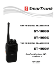
1
UHF FM DIGITAL TRANSCEIVER ST-2112D (450Mhz ~ 520Mhz) ST-2112C (400Mhz ~ 470Mhz) VHF FM DIGITAL TRANSCEIVER ST-2112V (136Mhz ~ 174Mhz) SmarTrunk Systems, INC. ST-2112UM R1.1 Printed in Malaysia FCC NOTICE This device complies with Part 15 of the FCC Rules. Operation is subject to the following two conditions: (1) This device may not cause harmful interference, (2) This device must accept any interference received, including interference that may cause undesired operation. FEDERAL COMMUNICATIONS COMMISSION INTERFERENCE STATEMENT This equipment has been tested and found to comply with the limits for a Class B digital device, pursuant to Part 15 of the FCC Rules. These limits are designed to provide reasonable protection against harmful interference in a residential installation. This equipment generates, uses and can radiate radio frequency energy and, if not installed and used in accordance with the instructions, may cause harmful interference to radio communications. However, there is no guarantee that interference will not occur in a particular installation. If this equipment does cause harmful interference to radio or television reception, which can be determined by turning the equipment off and on, the user is encouraged to try to correct the interference by one or more of the following measures: --Reorient or relocate the receiving antenna. --Increase the separation between the equipment and receiver. --Connect the equipment into an outlet on a circuit different from that to which the receiver is connected. --Consult the dealer or an experienced radio/TV technician for help. Page 2 THANK YOU! We are grateful you chose SmarTrunk for your land mobile radio applications. We believe this powerful, flexible and easy-to-use transceiver will provide dependable and reliable communications to keep personnel operating at peak efficiency. SmarTrunk transceivers incorporate the latest in advanced SDR technology. As a result, we feel strongly that you will be pleased with the quality and features of this product. NOTICES TO THE USER GOVERNMENT LAW PROHIBITS THE OPERATION OF UNLICENSED RADIO TRANSMITTERS WITHIN THE TERRITORIES UNDER GOVERNMENT CONTROL. ILLEGAL OPERATION IS PUNISHABLE BY FINE, IMPRISONMENT, OR BOTH. REFER SERVICE TO QUALIFIED TECHNICIANS ONLY. SAFETY: It is important that the operator is aware of and understands hazards common to the operation of any transceiver. WARNING: EXPLOSIVE ATMOSPHERES (GASES, DUST, FUMES, etc.) Turn off your transceiver while taking on fuel, or while parked in gasoline service stations. Page 3 ATTENTION (U.S.A. Only): The RBRC Recycle seal found on Smartrunk lithium-ion (LiIon) battery packs indicates Smartrunk‘s voluntary participation in an industry program to collect and recycle Li-Io batteries after their operating life has expired. The RBRC program is an alternative to disposing Li-Io batteries with your regular refuse or in municipal waste streams, which is illegal in some areas. For information on Li-Ion battery recycling in your area, call (toll free) 1-800-8-BATTERY (1-800-822-8837). Smartrunk’s involvement in this program is part of our commitment to preserve our environment and conserve our natural resources. PRECAUTIONS Observe the following precautions to prevent fire, personal injury, and transceiver damage. - Do not modify this transceiver for any reason. - Do not expose the transceiver to long periods of direct sunlight, nor place it close to heating appliances. - Do not place the transceiver in excessively dusty, humid, and/or wet areas, or on unstable surfaces. - If an abnormal odor or smoke is detected coming from the transceiver, switch OFF the power immediately and remove the optional battery pack from the transceiver. Contact your SmarTrunk dealer. Page 4 CONTENTS Contents Page APPENDIX I : TYPING……………………………….………………………….. 44 APPENDIX II : SELECTIVE CALLS............................................... 46 APPENDIX III: CONTACTS ........................................................ 48 APPENDIX IV: DEALER PROGRAMMED FUNCTIONS .............. 49 BATTERY CHARGER .................................................................. 11 CHARGING BATTERY FROM USB PORT .................................... 10 DISPLAY .................................................................................... 21 GETTING ACQUAINTED ............................................................ 18 ICONS ....................................................................................... 22 Installing the Antenna ST-FA0X ............................................... 15 Installing the Belt Clip .............................................................. 15 Installing/ Removing the LI-Ion Battery Pack.......................... 15 LED INDICATOR ........................................................................ 26 MAKING A CALL ....................................................................... 20 MENU ....................................................................................... 31 MENU ANNOUNCEMENTS .................................................. 38 MENU CONTACTS ................................................................ 42 MENU DISPLAY .................................................................... 35 MENU E-MAIL...................................................................... 40 MENU GPS ........................................................................... 39 MENU INFO ......................................................................... 43 MENU MESSAGES................................................................ 36 MENU RADIO ...................................................................... 33 PROGRAMMABLE BUTTONS FUNCTIONS ............................... 27 Page 5 ROTARY FUNCTIONS ................................................................ 24 SMARTRUNK ST-SBP18 .............................................................. 8 SWITCH ON/OFF AND VOLUME SELECTOR ............................. 26 UNPACKING AND CHECKING EQUIPMENT ................................ 7 Page 6 UNPACKING AND CHECKING EQUIPMENT Note: The following unpacking instructions are for use by your SmarTrunk dealer, an authorized SmarTrunk service facility, or the factory. Carefully unpack the transceiver. We recommend that you identify the items listed in the following table before discarding the packing material. If any items are missing or have been damaged during shipment, file a claim with the carrier immediately. Supplied Accessories Item Part number Quantity Battery pack ST-SBP18 1 Belt clip ST-2112BC 1 Screw set ST-2112BCS 1 Accessory connector cap ST-2112ACC 1 Instruction manual ST-2112UM 1 Smartrunk ST-2112 Transceiver ST-2112X 1 Desktop Battery Charger ST-BC-D01 1 AC Power adaptor ST-AC-D01 1 ST-FA0X 1 Antenna Before to start, you must read carefully about the battery and the battery charger operation, then assembly the radio as per the instructions bellow. Page 7 SMARTRUNK ST-SBP18 SMART BATTERY PACK RECOMMENDATIONS If not charged or used correctly, Lithium Polymer batteries may ignite without warning and cause serious injury and property damage. If you are unable to follow the safety recommendations then do not use them Do not charge Lithium Polymer cells on or near combustible materials including paper, plastic, carpets, vinyl, leather, or wood. Do not charge inside an automobile. Do not forcefully discharge the Lithium Polymer battery. Doing so will damage the pack. Never exceed the charge or discharge current rating. Do not expose Lithium Polymer cells to water or moisture at any time. Do not store or use Lithium Polymer batteries near an open flame or heater. Never use a Lithium Polymer battery that may have been subjected to damage or harsh handling. Carefully inspect the Page 8 battery and connectors for even the smallest damage. CAUTION: cells may be hot! Do not allow the electrolyte to get into eyes or on skin. Wash affected areas immediately if they come into contact with electrolyte. Do not alter or modify connectors or wires of a Lithium Polymer battery pack. NEVER incinerate used batteries. This may cause an explosion. NEVER use the charger when it is covered by objects that impede heat dispersal. Make sure battery and charger contacts are always clean; otherwise, batteries may not fully charge. Lithium Polymer batteries are different from Ni-Cd batteries in that it is not necessary to completely charge and discharge them to extend the battery life. Therefore, charging the battery when the remaining charge is under 10% and keep charging up to the battery reaches 90% is recommended to extend the battery life. If your batteries seem to have no capacity even after being fully charged, charge them again. If they do not retain a charge (or very little), new batteries must be purchased. Page 9 CHARGING BATTERY FROM USB PORT Your radio includes a built-in battery charger trough the USB radio connector. This feature allows the user to charge the battery with any USB cable connected to a source that can supply current for example PCs, USB ports, USB chargers, etc. Take notice most of the USB chargers are not for radios and the current supplied by these could be too low to charge the battery quickly. A radio receiving with high volume can demand more current than the current supplied by the USB charger meaning the battery will take long to be fully charged. To charge the battery just plug the USB cable into the USB connector in the radio, the radio will play a sound confirming the USB is already plugged. After unplug the cable, it is necessary to put again the USB connector cap to protect the radio from dust and harmful substances or gasses. Page 10 SMARTRUNK BC-D01 SMART BATTERY CHARGER Never leave the charger unattended. If you will be away from the charger then leave it unconnected from the battery. Charge all batteries on concrete, at least 10 feet (3 meters) away from combustible materials. Do not use if flammable liquids are in the area. Use this charger only with SmarTrunk Lithium Polymer battery packs. No other battery chemistry can be used. Do not charge a battery if it is hot. Allow them to cool first. AVOID charging in conditions of extreme cold (under 0°C; +32°F) or extreme heat (over +45°C; +113°F). Batteries may not charge under extreme temperatures. Do not charge any battery that appears to be swollen or damaged in any way. Do not disassemble the charger in any way. This is dangerous and will void the warranty. NEVER let metal, wire, etc. touch any internal part of the charger. Keep the charger away from children and animals. USE INDOORS ONLY! NEVER expose the charger to rain, snow or any liquids. NEVER insert battery pack/transceiver (with the battery pack attached) in a wet or soiled condition into the charger. This may result in corrosion of the charger terminals or damage to the charger. The charger is not waterproof and water can easily get into it. Page 11 1 2 3 4 5 6 7 9 8 10 The Smart Battery Charger is a device specially designed to recharge SBP18 battery pack compatible with ST-2112 SDR radio. This device has enough internal intelligence to exchange information with the battery under charge and improves charging regulation to extend battery life as much as possible, keeping risk out of battery damage by wrong recharging process. References: 1. DC main power supply (12Vdc @ 1A) 2. Negative terminal 3. Data terminal to exchange information with the battery pack. 4. Clock source to exchange data with the battery pack 5. Positive terminal Page 12 6. 7. 8. 9. 10. Battery guides Multi level indicator Remaining Charge LED Remaining Recharge time indicator Battery status indicator Operation: Load the battery pack SBP-18 alone using the battery guides (6) or just insert the complete radio ST-2112 with the battery on it. As soon as you load the battery, Charge LED (8) will let you know the charging process has started. Within the first two seconds, the ST BC-D01 will exchange information with the battery itself to knows about actual battery status (remaining charge, temperature, quantity of charging cycles, typical current load, etc). With all these information, the battery charger will adjust the re-charge parameters to maximize the battery life, getting the best performance for your radio. After the battery charger recognizes the battery and sets all parameters, the multi level indicator (7) will show the remaining battery charge, at the time the CHARGE LED (8) remains on. This process continues up to the charging process becomes stable, then the multi level indicator will alternate showing the battery charge and the time left to complete the charge. When the CHARGE LED is on, the information displayed into the multi level indicator, shows the real percentage of residual charge in the battery. Each led in the bar means 10% of the charge. So, if only three LEDs on the multi level indicator it means that the actual charge is about 25% to 35%. If 10 LEDs are on, then it means the battery has more than 95%. By cycles of 3 seconds, the indication will change from CHARGE to TIME LEFT. When TIME LEFT indicator LED is on, it means that the information represented on the multi level indicator bar expreses the time required Page 13 to complete the re-charging process. This is an estimation which may not be totally accurate because sometimes the battery temperature ask for slower charging rate, adjusting the estiation on the way. Each led on the multy level indicator when the TIME LEFT LED is on, represents 20 minutes of charging time to complete the battery. On this way, you can get a very clear information about the charging status, just reading the displayed function and the multi level indicator bar. End of charge: As soon as the re-charge process has been completed, the multi level indicator bar will blink at the time the Battery Life LED will blink also. On this case, the quantity of LEDs on the bar, indicates a draft estimation of the battery health. 10 leds means the battery is perfect. If less quantity of LEDs are blinking at the end of charge process, then it means the lithium polymerer composed is being degraded so battery performance will goes down. You can decide when the performance becomes too poor to buy a new battery, but anyway, the battery life indicator will let you get an approximate idea of battery health after the charging process ends. ST-BC-D01 gets information from the battery pack continously when connected to the battery. All parameters are controlled; the charging voltage and current are continuosly controlled on real time. If any of the parameters becomes out of normal status, the battery charger will abort the process, then all LEDs will blink quickly as an idication of charging failure. In case of failure, please remove the battery from the charger then wait few minutes before try it again. Sometime, the charging temperature is too high, or in case the radio is powered on, perhaps it demands too high current enlarging too much the target time to end the charging process. Battery failure indication will also appears if the battery elements are damaged or too aged. Page 14 Depending on the DC input voltage and the temperature, a complete process will demand between 3 and 4 hours. If the radio is on during the charging process, the time will extend, depending on the radio activity. Installing/ Removing the LI-Ion Battery Pack Only use the ST-SBP18 or ST-BP18 battery packs with this transceiver. 123- Match the grooves of the battery pack with the corresponding guides on the back of the transceiver. Slide the battery pack along the back of the transceiver until the release latch on the base of the transceiver locks. To remove the battery pack, pull off the battery lock and slide down the pack away from the transceiver. Installing the Antenna ST-FA0X Screw the antenna into the connector on the top of the transceiver by holding the antenna at its base and turning it clockwise until secure. Installing the Belt Clip If desired, attach the belt clip using the two supplied screws. Page 15 Note: If the belt clip is not installed, its mounting location may get hot during continuous transmission or when left sitting in a hot environment. Installing the Cap over the Speaker/ Microphone and USB port If you are not using an optional speaker/ microphone, install the cover over the SP/MIC/ext port jacks using the supplied screws. Page 16 Page 17 GETTING ACQUAINTED 1 13 2 7 3 9 4 8 5 10 0 6 11 12 Page 18 1. Rotary encoder Move clockwise or counterclockwise to change the selection according to the mode programmed for this encoder. 2. Power switch and Volume control Turn clockwise to switch ON the transceiver. Rotate to adjust the volume. Turn fully counterclockwise to switch OFF the transceiver 3. Transmit/ Busy/ Low Bat and message alert Lights red during transmission Green while receiving a call Blinks on red to show low battery status Blink on orange when any unread incoming message 4. Top Side Key Press to activate its programmable function. The function assigned to this key is designed by your dealer. 5. PTT (Push-to-Talk) switch Press this switch, and then speak into the microphone to call a station. 6. Bottom Side Key Press to activate its programmable function. The function assigned to this key is designed by your dealer. 7. Emergency/Top Key Press to activate its programmable function. The function assigned to this key is designed by your dealer. 8. Function Keys Press to activate its programmable function. The function assigned to this key is designed by your dealer. Page 19 9. Display It shows relevant radio status, messages and general information. See next page for additional information. 10. Keyboard Numeric and alphanumeric input device 11. Speaker 12. Microphone 13. Antenna MAKING A CALL To place a call to other party or group, please follow the steps: Press the PTT switch and speak into the microphone in your normal speaking voice. For best sound quality at the receiving station, hold the microphone approximately 1.5 inches (3-4 cm) from your mouth. Release the PTT switch to receive. Adjust the volume level as per your desire when receiving. If enabled by your radio programmer or dealer, your radio may have a time out timer, which can set a limit to the max length of your transmission without releasing the PTT. If it happens, you will receive a warning beep and message on the display. Page 20 DISPLAY Radio display splits the information in four different regions on idle mode. Icons Notification Area Bank Channel Icons: show important information as battery charge level, RSSI, and transmit power. It also shows which features are enabled such as Scan mode, GPS on, Digital or analog, etc. Notification area: shows relevant information as user ID/PTT ID or when a new event happens, the nature of the event (new message, call pending, etc) Bank: shows the name of the current set bank Channel: Shows the current channel. Notes: when the scan mode is active, the Bank and Channel notification area are replaced with the name of the scan group, unless the “revert channel” is set as “selected channel” then the selected Bank/Channel is shown. Page 21 On Menu mode, all display is used for the related Menu application, for example, to edit a text message or to check the complete battery status. ICONS Top area of the display is reserved to display icons. These icons represent radio status and are dynamically located on the icon area of the display. RSSI: Receive Signal Strength Indicator. Special care must be taken when the channel in digital mode because this indicator shows the average digital signal quality related to the BER (Bit Error Rate) on the channel and not the RSSI level. In transmit mode this icon shows an antenna and a letter indicating the real power transmit. Power: shows the transmit power Set. (L)ow, (M)edium,(H)igh,(A)uto. Speaker: this Icon represents the presence of audio in the radio Speaker (External or internal), then the Icon implies the radio is reproducing receive audio (Analog or digital) on the speaker. This is only for receiving audio not for generated tones or radio announces. Battery Status: shows the current charge level of the battery, If the battery is in charging mode (through the USB cable or in a desktop charger) this icon is alternated between the charge level and an arrow showing to the user the radio is currently being charged. Analog mode: this Icon shows to the user if the current channel is an analog channel. Page 22 Digital mode: this Icon shows to the user if the current channel is a digital channel. : Hybrid mode: This icon appears when the radio is operating on analog mode over a digital channel. Economy mode: The economy mode icon is shown when the radio is in a very efficient power demand. Special care must be taken in this mode because the first operation you try to do, possible will take more time than usual to be processed, because the complete radio must wake up before complete the demanded service. GPS: Shows the GPS status. If the GPS is enabled, then this icon appears on the screen. After the dish, the GPS status is qualified. A small cross means there is no attached GPS or the radio is not receiving information from external device, meanwhile if the GPS information is accurate, scaled bars represent the amount of satellites used to fix the GPS service: 1 bar, less than 4 satellites. Two bars appears if the quantity of satellites used to fix are between 4 and 8 satellites. If three bars are shown, more than eight satellites fixed. Envelope: New message has arrived and not read yet. Scan: Shows to the user that the radio is in scan mode. USB: This icon is shown when the radio has a locked connection to any USB host or an USB charger. Man running: if active, this icon shows the Man Running Emergency active status. Page 23 Man Down: This icon is displayed when the man down service is active. Summary of icons: ICON FUNCTION RSSI or Digital Signal quality Transmit mode and current power Active speaker Battery status Battery charge mode Analog channel Digital channel Hybrid mode: analog signal on a digital channel Econo mode GPS status New unread message Scan mode USB connected Man Running service active Man down service active ROTARY FUNCTIONS Top rotary switch function can be assigned to different associated functions in your dealer shop. Please check with your dealer the function assigned to this knob. Page 24 Possible functions are: None: Moving this selector do not generate any operation. Bank selector mode: move the rotary selector to change the current channel bank. Channel Bank: Select current channel relative to the bank. Scan Group Select: Select the current group of channel to scan between them. In this mode the radio is Scanning through all the channels programmed in the currently Scan group (programmed on the radio). When a call is received in one of the channels of the scan list, the radio stops, checks if the signaling match the one set for this channel then open the speaker or continue scanning according if the signaling matches or not. In which channel the call will take place if the user press PTT depends on the radio programming. Please ask to the radio dealer which mode is currently set. Trunking Group: in a trunking mode, this input can be used to select between the different trunking dispatch groups If the rotary is in in a non-programmed position, it will warn the user with an error tone. Page 25 LED INDICATOR A tri-color led indicator has been added on your radio to visual communicate the following status. Lights red: while transmitting. Lights green: while receiving. Flashes red: when the battery power is low, once per 2 second when battery charge is under the 5% and once per second when it’s less than 2%. Orange led blink: an unattended event is available (alert call, message received, etc.). These functionalities can be disabled on your dealer shop. Please ask to your dealer if you wish no lights on your radio. SWITCH ON/OFF AND VOLUME SELECTOR Turn clockwise to switch ON the transceiver. Rotate to adjust the volume. To switch OFF the transceiver, turn it counterclockwise fully. Your SDR radio has four additional functionalities, which can modify the current volume status: Minimum volume level: by programming, your radio can define the minimum audio level, even when the volume knob is completely close. On this way, it never loses a call due to low volume. Page 26 Emergency volume override: In case an emergency is on-going, you radio volume is controlled by the dispatcher who controls the emergency situation. Auto Volume: Your SDR radio can adjust the speaker audio level considering the level of the background noise in the environment where you are operating the radio. Privacy mode: The radio reduces the audio volume when located in certain angle close to your ear to let you avoid the disclosure of your communication. Please check with your dealer about the active features on your radio. PROGRAMMABLE BUTTONS FUNCTIONS Each function and side buttons can be programed as your desires. The functions of the front buttons (OK, BACK, HOME, and MENU) and navigations keys (Up, Down, Left, Right) are override when the user enters the menu. There are many possibilities for each key, regarding the long or short push. The functions to each key are assigned for your dealer on programming time. Functions of your keyboard are pre-assigned by your dealer or programmer. Please check the assigned function table already programmed into your radio. Some functions may not be active in your programming. Page 27 Bank Up: Selects the next bank in the bank list. If the rotary is also set for bank selector, this button action will still change the bank, overriding the top rotary switch position. If your radio is in the end of the list, it will jump to the first bank in your list (roll over) Bank Down: Selects the previous bank in the bank list. If the rotary is also set for bank selector, this button action will still change the bank, overriding the top rotary switch position. If your radio is in the first bank of the list, it will jump to the last bank in your list (roll over) Channel Up: Selects the next channel in the current channel list from current bank. If the rotary is also set for channel selector, this button action will still change the channel, overriding the top rotary switch position. If your radio is in the end of the list, it will jump to the first channel in your channel table (roll over) Channel Down: Selects the previous channel in the current channel list from current bank. If the rotary is also set for channel selector, this button action will still change the channel, overriding the top rotary switch position. If your radio is in the first channel of the list, it will jump to the last channel in your channel table (roll over) Power Up: Roll on the radio transmitting power. Possible values, Low/Mid/High/Auto. Power Down: Change the radio transmitting power. Possible values, Auto/High/Mid/Low. The power associated to High, Med or Low are adjusted by your dealer or radio programmer. Using the lower power for a communication will save the battery charge. Page 28 Monitor: Sets the radio in monitor mode. In this case, all the channel activity is heard in the speaker. If there is no carrier on the frequency, white noise is heard on the speaker. This mode overrides any signaling on the channel. Monitor Momentary: The monitor function is active as long as the button is pressed. When the button is released, the radio squelch mode is back to normal. This option only takes effect if is set in the press and hold (long push mode). This mode temporary overrides any signaling on the channel. Signaling Override: The CTCSS/DCS squelch mode is disabled. The radio will open the speaker when carrier is detected. Also overrides MDC signaling. Signaling Override Momentary: The signaling override function is enabled as long as the button is pressed. This option only takes effect if set in the press and hold (long push mode). Squelch Up: Increases the squelch level threshold. This operation increases the squelch level for all the channels in the radio. By programming, the squelch level of each channel can be adjusted individually. Squelch Down: Decreases the squelch level threshold. This operation decreases the squelch level for all the channels in the radio. By programming, the squelch level of each channel can be adjusted individually. Battery Status: Report by Voice annunciation (if enabled) and show on display the battery status. If your radio is equipped with ST-SBP18, it also shows the remaining operation time before the battery becomes empty, considering the average power demand of the last two minutes. In case the radio is on charge, by USB or battery charger, it will give you Page 29 information about the remaining time before the the charge process finishes. Displayed information is momentary. If you wish to read it continuously, please go through radio menu. The remaining operation time and the remaining charging time are representative but the accuracy depends on many variables, so it does not means a real time. If the operation conditions changes suddenly, the time prediction may fail. Changes on temperature or current on the charging source may also affect to this time estimation. RSSI/RDSI: (Receive Signal Strength Indicator/Receive Data Signal Indocator): Working on analog or FDMA mode, Voice report and display of current RSSI level. Displayed information is momentary. If you wish to read it continuously, please go through radio menu. If the radio is working on a TDMA channel, RSSI information does not give accurate information. On digital modes RDSI is the correct parameter to check for signal qualification. RDSI over 80% means a good communication quality. GPS Toggle: Turn On/Off the GPS receiver. Only available on models equipped with GPS. In case of use external GPS, this function has no effect. GPS On: Turn On the GPS receiver. Only available on models equipped with GPS. In case of use external GPS, this function has no effect. If it was already on, it causes no effect. GPS Off: Turn Off the GPS receiver. Only available on models equipped with GPS. In case of use external GPS, this function has no effect. If it was already off, it causes no effect. Menu: Launch radio main menu. Once in menu mode, front function keys have pre-assigned functionalities. Page 30 Scan: Active the Scan Mode. Scan Up: Select the Next Scan group into the scan list. Scan Down: Select the Previous Scan group into the scan list. Clear PTT ID: In normal operation mode, when any signaling is active, the PTT has an associated addressing to certain destination ID (private or group one). In case a temporary ID was assigned to the PTT, by keyboard or phone book, this button allows the user to clear it, going back to the default selection. MENU The radio menu gives the user a complete access to the radio for tuning it up and changing the behavior of it according to the user preference. Menu also gives you the possibility of access to advanced features as Messaging and E-mail Capabilities. Page 31 Menu tree: Battery RSSI Radio VOX Min Volume R. Beep Back Light Mode Display Back Light Level Back Light Time Reveived Messages Sent Fast Reply Compose Bank Squelch Mode Squelch Level Battery Main Menu Anounce GPS Power RSSI IDs Channel Status GPS Position Enabled Received E-Mail Sent Compose List Contacts Add Delete Info ESN Firmware Page 32 MENU RADIO Radio: This Submenu gives to the user the possibility of access the radio behavior, appearance and show status of it. Battery RSSI On Enabled Off VOX Radio Level Min Volume 0 .. 15 0 .. 255 On R. Beep Off Radio Battery: shows on the display the battery charge information, including percentage of charge and Time to Empty (TTE) estimated as per last two minutes average power demand. If the radio is on charge, TTE will be changed to Time to Full (TTF), as estimated time to complete the charge. This information will be continuously updated to the display. To exit this mode, press [MENU]. Radio continues in normal operational mode, but display will show this information instead any other related to the current channel and bank. Radio RSSI: shows on the display the Received Signal Strength (RSSI) continuously, expressed in –dBm. This information will be continuously updated to the display. To exit this mode, press [MENU]. Radio continues in normal operational mode, but Page 33 display will show this information instead any other related to the current channel and bank. Radio VOX: This option lets you to enable the Voice Operated Transmit control. If your radio has an external microphone connected to the external microphone input, then you can enable this option. Radio VOX Enable: Select this option to enable or disable the VOX operation. Once selected this step by pressing [OK], you will see the actual VOX status. To toggle current status use [UP] or [DOWN] arrow key, then save your selection by pressing [OK] Radio VOX Level: Select this option by pressing [OK] to adjust the threshold level of voice into your microphone to switch the radio to transmit mode. Once you enter on level alignment mode, use [UP] or [DOWN] arrow keys to adjust it to your desired value between 0 and 15. Radio Min Volume: Use this option to adjust the minimum volume level of your radio, even when the volume knob is at minimum. Once selected this menu step, use [UP] and [DOWN] arrow keys to select your desired level (0..255). Once selected the right volume, press OK to store it and go back to the Radio Menu. To exit, press [MENU]. Radio R. Beep: This option lets you to activate a beep tone to be sent over the air to other parties each time you release the PTT (Roger Beep). Use [up] or [DOWN] arrow keys to enable (ON) or disable (OFF) this feature, the press [OK] to store it. To exit, press [MENU]. Page 34 MENU DISPLAY Auto Back Light Mode On Off Display Back Light Level 0 .. 15 Back Light Time 0 .. 15 Display: This Submenu gives to the user the possibility of adjust the behavior of the radio display, backlight levels and timeouts. Display BL Mode: this step lets you select the back light operation mode. Use [UP] or [DOWN] arrow keys to enable (ON) or disable (OFF) or select (Auto) mode. Press [OK] to store it. To exit, press [MENU]. Display BL Mode Auto: Automatically controls the behavior of display backlight. The backlight will be turned ON if any key is pulsed or an incoming signaling matches the radio ID and automatically turned OFF after a programmable timeout. Display BL Mode On: Display backlight will be all time on. This feature is not efficient form battery saving point of view. Display BL Mode Off: Display Backlight never goes ON. Display BL Level: this step lets you select the back light bright. Use [UP] or [DOWN] arrow keys to adjust your desired bright (0 .. 15). Page 35 Press [OK] to store it. To exit, press [MENU]. Display BL Time: this step lets you select the back light timeout. Use [UP] or [DOWN] arrow keys to adjust your desired timer from 0 to 15 seconds. Press [OK] to store it. To exit, press [MENU]. MENU MESSAGES Received Messages Sent Fast Reply Resend Review Forward Delete Compose Message: this step will give you full access to the messaging capabilities. Send, Receive, compose, and fast reply. Note: The message feature is only available for any of the digital modes (FDMA or TDMA) and the user can only access to it if current channel is a digital one. Message Received: Use this option to read incoming messages. As soon as you press OK on this option, the display will show the latest incoming message. Scroll through all the list of incoming messages by pressing [UP] or [DOWN] arrows. Once you focus on the desired message, press [OK] to read it fully. Page 36 To exit, press [MENU]. Message Sent: Select this option to review all sent messages. As soon as you press OK on this option, the display will show the latest message sent from your radio. Scroll through all the list of sent messages by pressing [UP] or [DOWN] arrows. Once you focus on the desired message, press [OK] to read it fully. Press [OK] once more to get the message sent sub-menu, then choose the desired option: Resend, Forward or Delete it. Message Sent Resend: Automatically resend the message to the same destination. Message Sent Forward: lets you edit the message then, as soon as you press [OK] the radio ask to input the destination ID for the message. Use the keyboard to type the destination ID then press [OK] to send it. Message Sent Delete: Choose this option to erase the current message from memory. Once you select the right message, select this option, then you will be asked to confirm the action. You must press [OK] to confirm it or press [BACK] to jump one step back into the menu tree. Message Fast Reply: Choose this option to send a message from a pre-recorded list to any ID. Once you press [OK], you will see the list of pre-recorded messages enabled by your dealer. Use [UP] and [DOWN] arrow keys to scroll the list. Once focused the right one, press [OK] to confirm or [MENU] to exit. Once you select the right message, input the destination ID and press [OK] to send it. Message Compose: Use this option to create a new message to be sent. Once you press [OK], you will get the complete display to type the message using the keyboard. Page 37 Press OK once the complete message has been written, then the radio will ask you to type the destination ID for the message. Press [OK] to send it after the ID has been typed. After few seconds you will receive the message sent status (sent OK, failed or delayed) MENU ANNOUNCEMENTS Bank Squelch Mode Squelch Level Battery Anounce GPS Power RSSI IDs Channel Announce: Allows the user to the enable or disable the radio announces. Navigate, using [UP] and [DOWN] arrow keys, through the list of announcement to be activated or deactivated , then press [OK] to access to the programming mode. Use [UP] and [DOWN] arrow keys to switch the announcement feature ON or OFF then press [OK] to confirm the selection. Announce Bank: announce the current bank number. Played back each time you change the current bank. Announce Squelch: Announces the current squelch mode. Played back each time you change the squelch mode. Announce Battery: Announces the actual battery status, including the remaining charge in percentage and the time to finish the charge as per Page 38 the average of the last two minutes of current demand. It is played back when you press a programmed button to check battery level. Announce GPS: it announces the status of the GPS (ON or OFF). It is played back when you press a programmed button to change GPS status. Announce Power: It announces the current transmit power (High, Med, Low or Auto). It is played back when you press a programmed button to adjust the transmit power. Announce RSSI: It announces the current RSSI level when receiving an analog carrier or an FDMA carrier. It is played back when you press a programmed button to check the RSSI. Announce IDs: It announces the caller ID at the front of an incoming private call (Only on trunking mode). Announce Channel: It announces the current channel number on current bank. It is played back only when you change the channel. MENU GPS Status GPS Position Enabled GPS: Lets you to adjust current GPS status (on/off), shows the status of the GPS receiver and the current position if fixed. GPS Status: Shows on display the quantities of satellites used to fix. In case of not fixed yet, it will show NOT FIXED or GPS Disabled. To exit this screen press [MENU] or [BACK] to jump to GPS Menu root. Page 39 GPS Position: If fixed, it shows on display the coordinates in latitude and longitude of current location. To exit this screen press [MENU] or [BACK] to jump to GPS Menu root. GPS Enabled: lets you manually enable or disable the GPS on you radio (Only for ST-211xy-AG versions). Use [UP] or [DOWN] arrows to enable or disable the GPS then press OK to confirm you selection. Setting the GPS engine OFF will reduce the energy demand. MENU E-MAIL Received E-Mail Sent Compose E-Mail: Use this menu to create, read and send E-mails. Note: The e-mail feature is only available for any of the digital modes (FDMA or TDMA) and the user can only access to it if current channel is a digital one. ST-9116 or ST-9118 repeater with e-mail server engine must be present into your infrastructure and the service must be allowed for your radio ID on the way to send or receive e-mails. E-Mail Received: Use this option to read incoming e-mails. As soon as you press OK on this option, the display will show the latest incoming e-mail. Scroll through all the list of incoming e-mail by pressing [UP] or [DOWN] arrows. Page 40 Once you focus on the desired e-mail, press [OK] to read it fully. To exit, press [Menu]. E-Mail Sent: Select this option to review all sent e-mails. As soon as you press OK on this option, the display will show the latest e-mail sent from your radio. Scroll through all the list of sent e-mails by pressing [UP] or [DOWN] arrows. Once you focus on the desired e-mail, press [OK] to read it fully. Press [OK] once more to get the e-mail sent sub-menu, then choose the desired option: Resend, Forward or Delete it. E-mail Sent Resend: Automatically resend the e-mails to the same destination. E-mail Sent Forward: lets you edit the e-mail then, as soon as you press [OK] the radio ask to input the destination ID for the e-mail. Use the keyboard to type the destination e-mail address then press [OK] to send it. E-Mails Sent Delete: Choose this option to erase the current email from memory. Once you select the right e-mail, select this option, then you will be asked to confirm the action. You must press [OK] to confirm it or press [BACK] to jump one step back into the menu tree. E-Mail Fast Reply: Choose this option to send a message from a prerecorded list to any e-mail address. Once you press [OK], you will see the list of pre-recorded messages enabled by your dealer. Use [UP] and [DOWN] arrow keys to scroll the list. Once focused the right one, press [OK] to confirm or [MENU] to exit. Once you select the right message, input the destination e-mail address and press [OK] to send it. E-Mail Compose: Use this option to create a new e-mail to be sent. Page 41 Once you press [OK], you will get the complete display to type the e-mail using the keyboard. Press [OK] once the complete e-mail has been written, then the radio will ask you to type the destination e-mail address for the message. Press [OK] to send it after the address has been typed. After few seconds you will receive the e-mail sent status (sent OK, failed or delayed) MENU CONTACTS List Contacts Add Delete Contacts: Access to the phone book of your radio. Contacts List: list down all contacts defined in your radio phone book. Scroll through all the list of contacts by pressing [UP] or [DOWN] arrows. Once you focus on the desired contact name, press [OK] to select it. Once selected, you can address a private call to the selected contact by pressing PTT. To exit, press [MENU]. Contacts Add: Select this option to add a new contact to your phone book. Type the contact information by using the keyboard. Once you finish, press [OK] then complete the ID number or e-mail address for that contact. Press [OK] to save it in memory or [MENU] to escape. Contacts Delete: list down all contacts defined in your radio phone book. Scroll through all the list of contacts by pressing [UP] or [DOWN] Page 42 arrows. Once you focus on the desired contact name, press [OK] to select it then you will be asked to confirm the delete action by pressing [OK] or escape from this option by pressing [MENU] MENU INFO Info ESN Firmware Info: radio information a Firmware Version and Serial Number. Info ESN: Temporary shows the Electronic Serial Number of your unit. Press [MENU] to exit or wait for the time-out. Info Firmware: Temporary shows the firmware release loaded into your radio. Press [MENU] to exit or wait for the time-out. Page 43 APPENDIX I : TYPING Anytime you must type a message or contact name, you must use radio keyboard. Each key, when the radio is on typing mode, add one character to your text on cursor position. By pressing the same key repeatedly within a second, you can choose the new character to add with some key in agree to the following table: KEY 1 2 3 4 5 6 7 8 9 * 0 # CHARACTER 1!,~% abcABC2” defDEF3# ghIGHI4$ jklJKL5% mnoMNO6& pqrsPQRS7 tuvTUV8( wxyzWXYZ9 *.-+/)’^ [space] 0 _ < > ° ; : #;| To move the writing cursor to the Right/Left press the navigation key [RIGHT]/[LEFT] To jump the previous/next line, press the navigations key [UP]/[DOWN] To delete a char press the [BACK] key Page 44 To finish the Message and send it, press the [OK] Key. To leave the message press [MENU] Key. Page 45 APPENDIX II : SELECTIVE CALLS Some radio mode supports selective calling (Analog MDC, digital TDMA or Digital FDMA). By this reason, your radio has an associated ID. If your radio has been programmed with this feature, you will see your ID into the display notification area. In case you see only one ID into this area, then it means your radio is in all-call mode, which means your transmission will be received by all your partners each time you press the PTT. If you wish to make a selective call, then you have two options: A – Type the destination ID from the Keyboard then press [OK] B – Select the destination ID from radio’s phone book then press [OK] Any of the modes you choose, lets you address all your transmission to only one user. Destination ID could be also a group ID. After you select an ID, you can see the destination of your transmissions into the display’s notification area (for example 1001/1002). In case your destination ID is on your phone book, you can read the contact name into display’s notification area (for example 1002/Emily). To receive a selective call, a destination radio must have the selective call enabled. If so, only the enabled radio will receive each one of your transmissions when you press the PTT under a selective call mode. Page 46 The receive radio will decode also your ID and it will shows your into the display when it receives a selective transmission. In case your ID is already stored as a contact into the receiving radio’s phone book, then your name will be displayed. Receiving radio also learns how it should reply when a call is received. Your partner only must press PTT to reply to you in selective call mode simplifying the process. Both of the radios will remain in selective mode by fifteen seconds after the conversation is over. It is not necessary to address the selective call destination before you press the PTT during a conversation. Page 47 APPENDIX III: CONTACTS The contact list gives to the user, the possibility of associate numerical IDs with user-friendly names (Alphanumeric). The contact list can be accessed through the menu or using the Function Key programmed for this operation. The items on the phone list depend on the signaling mode of the current channel mode. For example, if you are operation an analog channel, when you check the phone book, you only can see the contacts names, which are compatible with such a signaling mode. If you are composing an e-mail, only e-mail contacts will be listed down on the phone book. Page 48 APPENDIX IV: DEALER PROGRAMMED FUNCTIONS Key Bank Up Bank Down Channel Up Channel Down Power Up Power Down Monitor Monitor Momentary Signaling Override Signaling Override Momentary Function Squelch UP Squelch Down Battery Status RSSI GPS Toggle GPS On GPS Off Menu Scan Scan Up Scan Down Default PTT ID Phone Book Cleat Hybrid Mode Page 49 Menu Home Back Bottom Side OK Top side Menu Emergency Home Long Push Back Bottom Side OK Top side Rotary Emergency Short Push