1
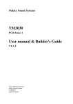
Oakley Sound Systems
TM3030
PCB Issue 2
Builder's Guide
V2.1.1
Tony Allgood
Oakley Sound Systems
CARLISLE
United Kingdom
Introduction
This is the Builder’s Guide for the issue 2 TM3030 sound module from Oakley Sound. This
document contains a basic introduction to the board, a full parts list for the components
needed to populate the board or boards, and a list of the various interconnections,
For the User Manual which contains an overview of the operation of the unit and the
calibration procedure please visit the main project webpage at:
http://www.oakleysound.com/tm3030.htm
For general information regarding where to get parts and suggested part numbers please see
our useful Parts Guide at the project webpage or http://www.oakleysound.com/parts.pdf.
For general information on how to build our modules, including circuit board population,
mounting front panel components and making up board interconnects please see our generic
Construction Guide at the project webpage or http://www.oakleysound.com/construct.pdf.
An issue 2 board awaiting its case and LEDs. This one has been built with a matched BC550B pair in the
VCF and a CA3080 and discrete buffer for the VCA.
2
Parts Information
For general information regarding where to get parts and suggested part numbers please see
our useful Parts Guide which is linked from the TM3030 project webpage or direct at:
http://www.oakleysound.com/parts.pdf.
Some special considerations for this project
I recommend to use a close tolerance polystyrene for the VCO timing cap, C9. This will give
better pitch stability. Use a cheaper part if you can accept a small drift in VCO pitch with time.
The PCB is laid out to accept the superbly specified 10nF LCR type EXFS/HR series.
Standard axial polystyrene types will fit into the board if mounted on one end. The working
voltage can be quite low, 63V is common.
Other alternatives to polystyrene are polypropylene. But make sure you get low voltage types
like 63V or so. Polypropylene capacitors are also used in suppression and can get very very
big.
The three ceramic capacitors should be ‘low-K', NP0, or C0G ceramic plates or dipped
ceramics. The lead spacing is 2.5mm.
I have also used some axial multilayer ceramics for the power supply decoupling on the digital
sections. These parts can be substituted with ordinary low voltage radial polyesters if you
wish. Watch out for the pitch spacing as the board is laid out to accept 0.3", 7.5mm, for these
devices.
The horizontal preset or trimmer resistors are just ordinary carbon types. No need to buy the
expensive cermet types for these positions. Carbon sealed units have more resistance to dust
than the open frame types. Piher make a suitable type to use here. Pin spacing is 0.2” at the
base, with the wiper 0.4” away from the base line.
The multiturn trimmers are the ones that have the adjustment on the top of the box. Spectrol
and Bourns make these. Some types are 22 turns, while others are 25 turns. Either will do.
They should have three pins that are in a line at 0.1” pitch. Don’t chose the 10-turn ones with
the adjustment on the end, they won’t fit on the PCB.
With the exception of the differential amplifier in the filter (Q36 & Q37) all the transistors
shown as BC549 on the schematic can be pretty much any NPN transistor that corresponds to
the same pin out. For example: BC550, BC548, BC547 etc. However, I recommend using
BC549 or BC550 as these are low noise devices. A BC550 is actually just a BC549 that can
operate at a slightly higher voltage. Quite often you see an A, B or C suffix used, eg.
BC549C. This letter depicts the gain or grade of the transistor (actually hfe of the device). The
TM3030 is designed to work with any grade NPN devices although I have used BC550B in
my issue 2 prototype.
3
The PNP transistors shown as BC559 on the schematic should be high gain BC559C or
BC560C types.
The SCR in the VCO uses different transistors. Here I have used BC212L and BC182L.
Although these are actually pretty ordinary transistors, they have a different pin out to the
other NPN and PNP transistors used in the TM3030. They also have the same pin out as the
Japanese parts used in the original device. You could substitute these three transistors with the
Japanese parts if you can get them. The BC212L is equivalent to the 2SA733P, and the
BC182L is equivalent to the 2SC536F. It is in my opinion that there are no sonic differences
between the European and Japanese parts in this part of the circuit.
The FET buffer of the VCO can be one of two parts. The PCB is laid out for both, but you
must ensure the one you use goes into the correct place on the board. Q1 should be a
2SK30A-O. Q2 should be a J201. Do not fit both. The original design and my own TB3030
used the 2SK30A-0 but these are quite tricky to find. In the TB3031 I used the J201, and I
still think this is a very good substitute for the Japanese part. In fact, it's possibly more
accurate since the variation between any two J201 devices may well be less than that of any
two 2SK30A-0.
I will leave the choice of device to you. However, I have tested both parts in the TM3030 and
recorded and compared the resultant audio output. I cannot tell the difference in the outputs
from the two types.
Q18 is also a 2SK30A-Y device. You should seek out this part if you want the envelopes to
behave in the same way as the original. Y types are easier to get hold of than O types, and
Senso at Vintage Planet should be able to supply you with one.
As we have seen the original design used two variants of the 2SK30A, the O and the Y types.
These two different types differ only by their value of Idss. This is the current that runs
through the device when the gate and source are grounded and the drain is taken to 10V. The
O types are defined as having a Idss of 0.6mA to 1.4mA. The Y types are defined as having
Idss of 1.2mA to 3.0mA. Look at the range of Idss for the 2SK30A-O. It is interesting to note
this, because the sound of the square wave is dependant on the Idss of the O type device. So
no wonder that people have commented some TB303s sound slightly different to one another.
The original Japanese NPN pair is the 2SC1583. It is a superb component and although not
made any more it is still available from some places. Matched NPN pairs are required in three
places in the TM3030, the exponential convertor, the filter ladder and the differential amp in
the VCF. Only in the differential amplifier have I made space on the board to take the
2SC1583. In the other two positions I have used modern substitutes.
For the exponential converter I have decided to use the easily available CA3083 in place of the
1583. There will be no sonic difference here and the CA3083 is more easily affixed to the
temp co resistor used in our design.
For the filter ladder the original design uses two matched pairs, one at the bottom of the
ladder, a 2SC1583, and one at the top, a 2SC2291. Although the 2SC1583 is available,
getting hold of the 2SC2291 is usually very hard. I didn't want to rely on builders getting this
part so I have chosen the THAT300P which has been used successfully in the earlier TM3030
4
and Oakley Diode Superladder modules. The THAT300 is four very well matched NPN
devices in one package. In my tests I found that this part sounds identical to the Japanese parts
and is therefore an excellent substitute.
THAT300P can be obtained from Profusion in the UK, Small Bear in the US, and also at
Mouser (part #887-300P14-U). It is a good part and is somewhat expensive.
The differential amplifier uses a single 2SC1583F in the original design. The TM3030 allows
for this if you can get hold of the 2SC1583. If not, then do not worry, as the board can also be
fitted with a hand matched pair of BC549B, BC550B, BC549C or BC550C transistors in
positions Q36 and Q37. Again, like the FET in the VCO buffer either the two transistors or
the 2SC1583 need to be fitted. Do not fit both U12, and Q36 and Q37.
As stated, if you are fitting them, Q36 and Q37 should be a matched BC549B, BC550B,
BC549C or BC550C pair. This means that both Q36 and Q37 should have identical
characteristics. It is unlikely that two randomly picked NPN transistors will be exactly the
same since the manufacturing process is not that precise. However, it is of my opinion that if
both transistors are of the same type, eg. both BC550C, and are bought new from the same
vendor and at the same time there is a very good chance that they will be matched well enough
for this application. Modern fabrication methods are much better than they used to be.
The VCA circuit also allows the builder some choice in the construction. The board is laid out
to accept either the original R-Ohm BA662 OTA chip, or a my own VCA design based
around the CA3080 OTA and a discrete buffer circuit. I have tested this part of the circuit
very thoroughly, and I am convinced there is little or no perceivable audible difference in the
two designs.
It should be said that both OTA chips are now obsolete, but the CA3080 is still available from
many sources. Small Bear and Senso both carry this part.
In either case, do ensure that you build your choice correctly. The 3080 design uses an
additional FET (Q35) and resistor (R118) and neither of these should be fitted if you are using
a BA662.
For the dual op-amps in the TM3030 I have specified the same parts as used in the original
unit. These are AN6562 devices. They have a very large input voltage range, that includes
zero volts, so they cannot be substituted with more common op-amps like the TL072.
Alternatively you can use the LM358 instead. This is a good part and although it does behave
slightly differently to the AN6562 in some conditions it does seem to not change the
TM3030's sound in any way.
The AN6562 devices are available from Senso for a modest amount. You need two of them,
one for the VCO circuit, the other for the power supply.
The PIC is a special programmed device that is supplied when you buy the PCB. Spare preprogrammed PICs, should you break yours, are also available for a small charge. Neither
Sequentix or Oakley Sound will provide the firmware separately.
5
The other semiconductors used in the TM3030 are standard parts that you should be able to
get from your local parts supplier.
The PTC is a 1K +3500ppm/K positive temperature coefficient resistor. This means its
resistance goes up with temperature. It's there to keep the VCO’s frequency relatively stable
as the ambient temperature changes. The PTC I now use for this job is made by KRL in the
US. They can be most easily obtained from Senso's Vintage Planet. They are described as 'Tel
Labs Q81' equivalents and Senso's part number is: SC-R-118.
Other PTCs do exist and good use can be had from the cheaper Meggitt series. Farnell part
number 1174306. It's a 1K +3000ppm/K 900mW device. The old TB3030 used this part and I
thought it was great until I tried the KRL parts. I can simply say that once fitted the KRL
parts give much better stability over a wider range of temperatures.
Input and output sockets are not board mounted. You can choose whichever type of sockets
you wish. However, to reduce the possibility of earth loops you may be wise to use plastic
sockets for the audio output socket.
The LEDs can be any type, although I recommend the use of standard round 3mm types. You
will need to bend their legs if you want them to stick through the panel. More detail about
mounting the LEDs is given on this later on this document. Many manufacturers do ready
made preformed LEDs in little plastic boxes. These may be perfect for the job, but be careful
that your LEDs have the cathode on the right hand side as you look at the front of the device.
The suggested colours for the LEDs are just that, suggestions. You can chose any colour you
want for any of the LEDs. However, bear in mind some of the blue LEDs will appear brighter
unless you step down the current with a bigger current limiting resistor.
The front panel switch can be any style if you are not fitting it directly to the PCB. However,
the PCB is designed to use the miniature toggle range from C&K. Ones made by Multicomp
also fit very nicely. The switch should be an ordinary ON-ON switch, sometimes called SPDT.
The C&K types are ‘type 2 horizontal’ non-sealed units. C&K’s part number is
7101MD9AV2BE. Farnell part number: 9575502. Multicomp switches are similar and can
also be obtained from Farnell. The Multicomp part number is 1MS1T2B4M7RE. Farnell sell it
as part number: 9473297.
The power on switch will probably be fitted to the rear of the unit if you are using a half rack
case or fitting two TM3030 units in one 1U rack. You can chose any type of switch you fancy,
but I normally go for ones that need a circular mounting hole since these are easier to fit.
The power inlet socket should be one to match your choice of wallwart supply. However, it is
important that you chose an insulated design, ie. one made from a plastic housing. It is
imperative that you do not let either of the input power leads connect to the chassis.
Sometimes people like to substitute parts in place of my own recommendations. Feel free to
do this, but remember that there is normally a good reason why I have selected that particular
part. If you do find that, say changing an transistor with another one, makes an improvement,
please do let me know via the Oakley-Synths list or our forum at Muffwigglers.com.
6
Parts List
I strongly advise you to read the 'Parts Information' section above before you place any order
for parts.
For general information regarding where to get parts and suggested part numbers please see
our useful Parts Guide at the project webpage or http://www.oakleysound.com/parts.pdf.
A quick note on European part descriptions. To prevent loss of the small ‘.’as the decimal
point, a convention of inserting the unit in its place is used. eg. 4R7 is a 4.7 ohm, 4K7 is a
4700 ohm resistor, 6n8 is a 6.8 nF capacitor.
Resistors
All resistors 1/4W 5% unless stated.
10R
22R
100R
220R
1K
1K5
1K8 1% metal film
2K2
2K2 1% metal film
3K3 1% metal film
3K9 1% metal film
4K7
5K1 1% metal film
6K8
10K
10K
10K 1% metal film
22K
47K 1% metal film
51K 1% metal film
68K
100K 1% metal film
100K 0.1% metal film
180K
200K 0.1% metal film
220K 1% metal film
220K
1M
1M5
R60
R65, R70
R88, R89, R113, R14, R61, R42
R1,R9,R10
R4, R117, R104, R84, R31, R64
R106
R85
R12, R29, R109, R112, R107, R110, R63, R44, R43,
R94, R59, R58, R80
R91
R40
R50
R119
R38, R72
R74
R6, R13, R7, R116, R114, R100, R51, R97, R78, R77, R79,
R57, R46, R83, R62, R67, R53 ,R52 ,R69, R68, R5
R118 - only if not fitting BA662 in U15.
R71
R95, R11, R92, R93, R54, R41, R73, R66
R2, R96, R102, R39
R105
R56
R28, R8, R33, R108, R32, R35, R101, R103, R99, R115, R36,
R37, R90, R30, R55, R75, R76, R82, R49, R47, R81, R120
R16, R18, R20, R22, R24
R3
R15, R21, R25, R26, R23, R19, R17
R27
R45, R98, R48, R86
R111, R34
R87
7
1K +3500ppm/K
PTC
- see text for mounting information.
Capacitors
10nF 1% polystyrene
33pF ceramic plate
330p ceramic plate
3n3, 100V polyester
1nF, 100V polyester
10nF, 100V polyester
15nF, 100V polyester
33nF 100V polyester
47nF 100V polyester
100nF, 63V polyester film
220nF, 63V polyester film
330nF, 63V polyester film
100nF, 63V axial ceramic
1u0, 63V elect
2u2, 63V elect
10uF, 35V elect
22uF, 35V elect
47uF, 35V elect
470uF, 35V elect
C9
C1, C2
C21
C30
C12
C11
C29
C41, C23, C28, C24
C32
C31, C6, C49, C47, C33, C34
C14
C56
C5, C7, C10
C37, C13, C55, C52, C19, C53, C51, C42, C46, C44, C35,
C43, C15, C20
C22, C8
C54, C48, C27, C38, C36, C50, C17, C18, C25
C4, C3
C45, C26, C39, C40
C16
Discrete Semiconductors
1N4004 power diode
1N4148 signal diode
BC182L NPN transistor
BC212L PNP transistor
BC550 NPN transistor
BC550C NPN transistor
BC560C PNP transistor
J201 FET
J201 FET
2SC1583 NPN pair
2SK30A-O FET
2SK30-Y FET
CA3083 NPN array
THAT300P NPN array
D7, D6, D4, D3
D2, D14, D1, D5, D8, D13, D12, D10, D9, D11
Q5, Q4
Q3
Q34, Q9, Q10, Q27, Q8, Q26, Q7, Q20, Q19, Q21, Q15, Q14,
Q29, Q30, Q24, Q25, Q12, Q17, Q23, Q13
Q36, Q37 - matched pair, see text.
Q31, Q6, Q33, Q32, Q11, Q16, Q22, Q28
Q35 - only if not fitting BA662 in U15
Q2
- only if not fitting 2SK30A-0 in Q1
U12 - only if not fitting Q36 & Q37
Q1
- only if not fitting J201 in Q2
Q18
U6
U9
8
Integrated Circuits
4050 hex non-inverting buffer U5, U4
4066 quad analogue switch U8
6562 or LM358 dual op-amp U7, U13
6N137 opto coupler
U2
LM723 voltage regulator
U10
78L05 +5V regulator
U1
BA662 Roland OTA
U15 - fit only if not fitting CA3080 in U14)
CA3080 OTA
U14 - fit only if not fitting BA662 in U15)
PIC18F242 TM midi-chip
U3
- supplied with PCB
Trimmers
2K multiturn cermet
10K multiturn cermet
50K multiturn cermet
470K horizontal carbon
PSU
V/OCT
PITCH
FREQ, OFFSET
Pots
All Alpha 16mm types with seven matching brackets. Note Alpha and ALPS use A and B
suffixes on their pot values. A = log and B = linear.
1M log
50K lin
50K lin x 2 (dual gang)
50K log
DECAY
TUNE, ENV_MOD, FREQUENCY, ACCENT
RESONANCE
VOLUME
Miscellaneous
4.000MHz crystal
5-pin DIN socket
1/4" jack socket
2.5mm power inlet
Power switch
LED 3mm red
LED 3mm green
LED 3mm yellow
SPST toggle switch
Knobs
X1
- see text for mounting information.
MIDI_IN, MIDI_OUT
AUDIO_OUT
AC_POWER
SLIDE, ON
GATE
ACC
WAVE
Seven off to suit pot shafts
Also you will need solder, connecting wire of some sort and a case to put it all in. You may
want to use IC sockets for all the ICs. I do recommend that you use an 28-pin 0.3" wide IC
socket for the PIC.
9
Populating the TM3030 PCB
For general information on how to build Oakley projects, including circuit board population,
mounting front panel components and making up board interconnects please see our generic
Construction Guide at the project webpage or http://www.oakleysound.com/construct.pdf.
There are a few things I ought to draw your attention to that are not covered in the
Construction Guide.
1. The 4MHz crystal case is larger than the issue 2 PCB is laid out for and fitting it will foul
the neighbouring ceramic capacitors. You must therefore fit C1 and C2 first. X1, the crystal, is
then soldered in place so that the base of the crystal's casing is resting on the top of the two
ceramic capacitors. Although this is not a standard way of mounting the crystal it will not
cause any problems to do so.
2. The positive temperature coefficient (PTC) resistor is mounted so that is lies across the top
of U6. This is to ensure that both it and U6 are at the same temperature so that the resistor
can compensate for the temperature dependency of the VCO control circuitry.
A close up of the VCO circuitry of the TM3030. Note the positioning of the positive temperature
coefficient (PTC) resistor. Although not used here, a small amount of thermal paste can be used to keep
both U6 and the PTC at the same temperature.
10
3. If you are not fitting a 2SC1583 to the filter circuit then you need to use a matched pair of
BC550B or BC549B transistors. In theory these should be perfectly matched and thermally
bonded together. One way of thermally connecting them is to tie them together with a cable
tie as seen in the photograph below.
Two BC550B transistors face to face and fixed together with a simple cable tie. Again, a small amount of
heat conducting paste can be used if desired.
11
Mounting the Pots, LEDs and Switches
If you are using the recommended Alpha pots, then they can support the PCB with specially
manufactured pot brackets. You will not normally need any further support for the board.
When constructing the board, fit the pot brackets to the pots by the nuts and washers supplied
with the pots. Now fit them into the appropriate holes in the PCB. But only solder the three,
or six, pins that connect to the pot. Do not solder the pot bracket at this stage. When you
have soldered all the pots you can fit the board to your front panel. Position the PCB at right
angles to the panel, the pot’s own pins will hold it fairly rigid for now. Then you can solder
each of the brackets. This will give you a very strong support and not stress the pot
connections.
The Alpha pots are labelled with an A or B suffix. For example: 50KB or 1MA. Alpha and
ALPS do the opposite to our European convention and use A = log and B = linear. So a 1MA
is a 1 megohm log pot.
The four front panel mounted LEDs must be fitted carefully if you are using the directly
mounted technique. Although this sounds fiddly, it's actually quite easy and it reduces wiring,
interference and possible errors.
A close up of the LEDs in a 19” rack mounted issue 1 TM3030. You can see that the LEDs simply poke
through the front panel.
Remove the front panel so that you just have the board again. Get the four LEDs and find the
cathode for each one. Make sure the cathode of the LEDs will go into the round pad, pin 2, on
the board. Carefully bend the LED’s legs at a point 6mm away from the plastic body of the
LED. The legs should be bent by 90 degrees so that the legs are pointing straight down.
Check to see if they fit into the board. The bottom of the LED’s body should fit just flush to
the board edge. Fit all four LEDs to the board but do not solder them in at this stage. Let their
legs poke through, there’s no need to cut them down yet. Now fit the front panel again to the
board and tighten the pot nuts. You should find that the board now fits snugly into position
12
and each LED should be just poking out of its hole neatly, albeit loosely. Align the LEDs if
they aren’t quite straight and solder each one in turn, trimming its leads nice and short
afterwards.
With panel removed once again, you can now fit the switches. The C&K PCB mountable
switch should fit tightly into its respective holes on the board. You may need to use a pair of
fine nosed pliers to help the flexible gold pins into the board holes.
Make sure the switch body is flat against the board. Now refit the front panel and make sure
the round switch barrel fits into its hole in the front panel. Now solder all the pins on the
switch including the securing pins to the front.
That completes the soldering of the front panel components.
13
Housing your unit
The PCB has been designed to fit into a standard 1u high 19” rack or half rack unit. Your
local parts distributor should have these. However, good rack units can be quite expensive and
will contribute heavily to the final cost of your completed TM3030. Expect to pay around
40GBP or so.
Your choice of case will also be affected by what else you want in your enclosure. It is
possible, in theory at least, to fit two TM3030 units side by side in a 1U rack case. This does
depend on the rack case you have chosen, but most should have the front panel space to allow
this. If you are choosing to use an internal mains supply, make sure you give yourself enough
room for the transformer and associated wiring.
In the UK Bryant Broadcast, Holt Broadcast Services, Electrospeed and RS Electronics Ltd
do have a range of rack units that may be suitable.
The Bryant and Holt Broadcast ones are both superbly made, but they do not allow you to use
the standard 3mm thick Schaeffer front panel. Their cases utilise the front panel as part of the
enclosure. Simply swapping the Bryant/Holt panel with one obtained from Schaeffer will not
work. Of course, if you are drilling out the Bryant/Holt panel to any Schaeffer plan, then this
would indeed work wonderfully. Both Bryant and Holt do custom metal work, so it may be
possible to try their services. This is one area I would like to try in the near future. Another
option is to send the plain Bryant or Holt front panel to Schaeffer for engraving. Contact
Schaeffer for details of this service but don't expect it to be cheap.
If you buy the cases made by Vero from Farnell and others, you will find that the height of the
unit internally is quite restricting. The bottom and lower panels have 6mm folds in them at the
front. This effects the amount of space available for the pots and circuit board at the front
panel. It is possible to use these cases as I have done in the past, but I needed to cut back the
three pins on each pot to prevent them shorting with the case. The pot bracket pins actually
prevent the case from then touching the pot’s pins. This is all right, but you really need to
allow a minimum of 0.5mm slack when you fit the front panel to the case.
The second issue 1 TM3030 I built. This one has been built into a 19” rack from Holt Broadcast. The
front panel legending is achieved with a perspex overlay.
The other choice is to fit the TM3030 into a half rack. My first issue 1 TM3030 prototype was
built into a half rack width two tone metal case from RS Components Ltd. Their part number
is 222-020. Unfortunately, you will need to do some rework on the internal bracketry to allow
14
the board to fit in without fouling the side supports. The nice thing about these cases is that
although the main surrounding is made from steel for strength, the front panel is made from
folded aluminium and so is easy to cut and shape holes.
My first issue 2 TM3030 fitted into the three part metal case from RS Components (pt no: 222-020).
I should point out that the best performance will always come from using metal cases. Metal
cases are not only more rugged but they also provide screening. A good grounded case will
protect the TM3030 from extraneous radiation from CRTs, amplifiers and computers. The
TM3030's VCO is particularly susceptible to mains hum fields. Although the PCB layout is
carefully done to minimise this, if you fit your unit into a plastic or wooden case, you may find
that you will get a little 100Hz or 120Hz wobble in the unit's pitch. You can use some
aluminium foil to shield the circuitry, this can be stuck down on the lower part of the case,
underneath the PCB, and connected to the GND pad of the TM3030. Do not connect your
screening to any lug of the power pack inlet socket though.
When using any metal case it is essential that the case is grounded so that the screening is
most effective. Grounded means electrically connecting the metal case to the 0V or ground of
the circuitry. The GND pad provides a handy point from which to wire your panel's metalwork
to. However, you will probably not need to use the GND pad at all if you have used metal
midi sockets or a jack socket with a metal bush. See the chapter on midi, power and audio
connections for more details on this.
15
For those of you fitting an internal toroidal transformer you must make sure there is no way
the bolt that secures the transformer can touch both the bottom and top of the metal case. If
the metal support of transformer together with the case makes a complete loop around the
core, then you have a shorted one turn secondary. (‘Well, there was a large hum, more of a
buzzy rattle really, then a smell of burning rubber and then a lot of smoke... ’). You may also
like to consider the use of a nylon bolt to hold the transformer in place.
When an internal transformer, toroid or otherwise, is being used then the metal case must be
connected securely to earth. This is best done with a M4 bolt, nut, toothed washer and
solder tag directly wired (with thick wire) to the IEC inlet socket's earth tag. The TM3030's
circuitry should be then tied to earth via another wire from the GND pad on the board back to
the bonding point.
There is little more information about using internal mains transformers later in this document.
I should stress that building a component level mains transformer into any DIY project should
not be taken lightly as the consequences for getting it wrong can be severe.
The PCB will be supported well enough by the pots and pot brackets. However, this may give
some people nightmares so it for them it will be a good idea to provide additional support.
Small holes, to fit M3 bolts, have been provided on the outer corners of the PCB to do this.
Feel free to enlarge these holes if you wish. My prototype has been very happy just supported
by the pots. However, my unit doesn’t get moved around much. If you intend to take it out on
the road, extra support may be a good idea.
16
Midi, Power and Audio Connections
The prototype had its input and output sockets mounted on to the PCB itself. This initially
seemed quite practical, but in reality would only be useful if everyone was going to be using
the same casing. In the production run we have used 0.1" headers for all the I/O connections.
This should give you more flexibility in making your unit suit your own needs. The TM3030
board will be held in place in the case either by the pot brackets or the four mounting posts.
The sockets should then be mounted onto the rear panel and then hand wired to the PCB.
0.1" headers are commonplace on commercial units to speed up manufacture. You can use
either Molex [strip and crimp] or MTA [insulation displacement] type connectors. For those
who haven't a clue about either of these forms, it is probably best for you to just to solder the
connecting wires in place. 0.1" headers are useful and easy to use, but both types require
special and relatively expensive tools to make up the wiring. So, for many of you it will be
easier to simply solder the wires into the correct holes on the TM3030 PCB.
The type of wire is often asked about on the forum. I use multistrand hook up wire and this
often comes in hobbyist packs of varying colours. The size that I use is typically described as
7/0.2mm which is seven strands of 0.2mm diameter wire. Don't use single strand wire since
this tends to break easily. Remember to keep all wires as short as you can, but allow for a little
extra so that no wire will ever become taut. I usually tin the bare wire ends with a bit of solder
before I place the wire into the board or terminal hole. This stops the wire end from fraying
and makes a better solder joint.
NOTE: Pin 1 of the headers are denoted by a square solder pad on the PCB. All the others are
round.
You have just four sockets to wire up and it doesn't take long at all. Lets deal with the power
inlet first. You'll probably want to include a power switch, but this isn't shown on any of the
schematics. If you have chosen a nice SPST switch, it will only have two terminals. Simply
wire this in series with one of the connecting wires from the power inlet to the PCB.
If you are using a metal case then the power inlet socket should not have a metal mounting
bush. That means that it should not have any metal part on main body of the socket touching
the TM3030's metal case. We do not want any direct connection from the power supply's
wiring to connect to the case.
The power inlet socket has two or three terminals. The ones you need are the terminals that
connect to the the inserted power plug. The third terminal is the 'normally closed' lug,
sometimes called the NC or normalising lug. This should be ignored in our application. The
header labelled AC_POWER will connect to the power inlet and the power switch.
Pin 1 of AC_POWER should go to any terminal on the switch. Pin 2 should go to any of the
two terminals on the power socket that are not the NC lug. You should connect the other
terminal on the switch to the other terminal on the power inlet that isn't the NC lug.
Remember the TM3030 uses a bridge rectifier on its power input, so it doesn't matter about
the polarity of the input voltage.
17
The next socket we shall wire up is the audio output. This should be a 1/4" jack socket and
you can use either plastic framed sockets (with a plastic securing nut) or ones with a metal
bush (and metal securing nut). Both types will probably have three lugs, but may have six or
just two. You will be connecting only to the terminals that will connect to the tip and sleeve of
the connected jack plug.
Connect pin 1 of AUDIO_OUT to the terminal that will connect to the tip of the jack plug.
This wire will carry the audio signal. Connect pin 2 of AUDIO_OUT to the terminal that
connects to the sleeve of the jack plug. This is the 'earth', or ground, of the signal.
Now if you have used a socket with a metal bush and securing nut and have a metal case then
the jack socket will have grounded your case. By grounding your metal case you will help
screen the internal circuitry from outside electrical interference. To help make a good
connection with the case it is best to use a toothed or sprung washer between the socket and
the inside of the case. If you have a plastic output socket do not worry you'll be grounding
your case with the midi sockets.
A close up of an older issue 1 TM3030 showing the midi connections done with Molex KK 0.1” headers
and housings. Issue 2 boards can be wired in a similar way.
Wiring the midi sockets often causes the most confusion since it's sometimes difficult to know
which pin goes to where. Midi sockets are numbered in a most confusing way. If you get this
wrong the TM3030 won't be damaged, but it will not operate correctly.
18
When you look at the back of a midi socket, you will see six terminals. If you are lucky then
they will be labelled, but quite often they are not. We will firstly consider the five of them that
form a half circle. If you position the socket so that the middle terminal is at the top, then the
pin numbers go 3, 5, 2, 4, 1. Pin 2 is therefore at the top. The sixth terminal is normally
opposite to pin 2 and connects to the metal surrounding of the socket. We shall call this pin
the 'sleeve' pin.
x2
x5
x3
x4
x1
x Sleeve
The midi sockets are wired up as follows:
MIDI_IN
Pin 1 on PCB goes to Pin 4 on socket
Pin 2 on PCB goes to Pin 5 on socket
MIDI_OUT
Pin 1 on PCB goes to Pin 4 on socket
Pin 2 on PCB goes to Pin 2 on socket
Pin 3 on PCB goes to Pin 5 on socket
If you have used a plastic audio output socket then you should also connect pin 2 on the midi
output socket to the sleeve solder tag. This can normally be done with a small length of solid
core wire on the socket itself. By making this connection you will have connected the metal
case to 0V (ground) and screened your case.
If you have used plastic midi sockets, or have metal ones with no sleeve connection, along
with a plastic output socket you will have to ground your case another way. Drill a 3mm hole
into your metal case at the rear. Fit an M3 screw through this hole and with a nut, toothed
washer and solder tag create a grounding point on the inside of your case. Then connect a
wire from this grounding point to the GND pad on the TM3030 PCB.
That completes the wiring of the TM3030.
19
Fitting an Internal Mains Transformer
I do not endorse, nor recommend, any method that uses the direct powering of any Oakley
equipment with the mains supply. It is up to you to use your PCB wisely and to make sure you
make your project in a safe manner. Furthermore you should ensure that the finished project is
safe to any persons who are using it. Oakley Sound Systems cannot take any responsibility for
your actions with this board.
The following advice is only for those who know how to wire mains rated equipment safely. If
you do not know how to do this then make no attempt to do so. The following information,
provided in italics, is the only information I am prepared to give regarding direct mains supply
for the TM3030.
Transformer rating: Secondaries: 15-0 or 7.5-0-7.5 @ 3VA minimum
Do not connect the common of any dual secondary windings to ground. Winding end wires
go to pin 1 and pin 2 of the connector marked AC power. Neither pin 1 or pin 2 should be
connected to ground.
C16 should be adequately rated for the input voltage you are using. ie. At least equal to
1.4xVac. Where Vac is the maximum output RMS voltage of the transformer.
Line fuse: T250mA
All mains carrying conductors must be suitably insulated and mounted away from the low
voltage parts of the unit.
All parts of the metal case MUST be connected to mains safety earth. A suitable and secure
bonding point must be made to the case. Note that any case paint or other coating should be
removed from around the bonding point to ensure that the metalwork is making a good
contact to the bonding point hardware. The bonding point should then be connected via a
suitably thick piece of wire back to the earth terminal of the IEC socket or earth inlet
connection.
If you have used a laminated EI transformer, ie. not a toroid, then you should earth the
exposed metal frame of the transformer.
0V on the TM3030 circuit board should also be tied to earth. This should be done using a
piece of insulated wire connecting the earth bonding point to the GND pad on the board. In
this instance only it will be preferable to use a plastic audio jack socket and not connect the
sleeve of the midi output socket.
20
Final Comments
If you have any problems with the module, an excellent source of support is the Oakley Sound
Forum at Muffwiggler.com. Paul Darlow and I are on this group, as well as many other users
and builders of Oakley modules.
If you can't get your project to work, then Oakley Sound Systems are able to offer a 'get you
working' service. If you wish to take up this service please e-mail me, Tony Allgood, at my
contact e-mail address found on the website. I can service either fully populated PCBs or
whole modules. You will be charged for all postage costs, any parts used and my time at
25GBP per hour. Most faults can be found and fixed within one hour, and I normally return
modules within a week. The minimum charge is 25GBP plus return postage costs.
If you have a comment about this user guide, or have a found a mistake in it, then please do let
me know. But please do not contact me or Paul Darlow directly with questions about sourcing
components or general fault finding. Honestly, we would love to help but we do not have the
time to help everyone individually by e-mail.
Tony Allgood at Oakley Sound
Cumbria, UK
© July 2011 – updated December 2012
21