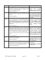
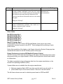
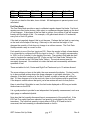
1
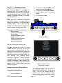
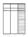
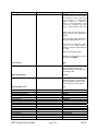
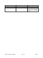
GRT HORIZON
Models HX, HS & WS
Set Up & Configuration Guide
Rev. A
February 2009
Grand Rapids Technologies, Inc.
3133 Madison Avenue SE
Wyoming MI 49548
616-245-7700
www.grtavionics.com
INTENTIONALLY BLANK
GRT Horizon Set Up Guide
pg. ii
Rev A
FORWARD
Welcome to Grand Rapids Technologies’ GRT Horizon! We are pleased that you have
chosen our product to meet your flying needs.
Visit the Grand Rapids Technologies (GRT) website ( www.grtavionics.com ) for the
latest updates and supplemental information concerning the operation of this and other
GRT products.
This manual describes the operation of GRT Horizon EFIS using the software version
shown in the Record of Revisions. Some differences may be observed when
comparing the information in this manual to other software versions. Every effort has
been made to ensure that the information in this manual is accurate and complete.
GRT is not responsible for unintentional errors or omissions in the manual or their
consequences.
Copyright © 2001 - 2009 Grand Rapids Technologies or its subsidiaries. All rights
reserved.
Information in the document is subject to change without notice. Grand Rapids
Technologies reserves the right to change or improve their products and to make
changes in the content of this material without obligation to notify any person or
organization of such changes or improvements.
CAUTIONS
WARNING: Obstacle clearance is not assured in Synthetic Approach Mode.
WARNING: Various functions of this system may be incomplete or untested. Please
exercise caution when using the EFIS until a software update and a user manual
corresponding to the software version are provided.
CAUTION: If any display unit is inoperable, the display units will not be able to swap
information. The pilot must account for this down-graded mode of operation and not
expect data will transfer between displays.
CAUTION: If GPS position data is lost for more than 30 seconds, the EFIS Horizon
issues a No GPS Position warning and automatically reverts to dead-reckoning using
the AHRS heading, true airspeed, last known winds and time. This data is used to
estimate changes in position, which are applied to the last known GPS position to give
an approximate navigation solution. The accuracy of the dead-reckoning function will
degrade with time depending on the accuracy of this data and changes in the winds.
CAUTION: When the ground track indicator is hollow, indicating it is display limited, the
ground track indicated is necessarily inaccurate. This means the aircraft’s track over
GRT Horizon Set Up Guide
A
pg. iii
Rev
the ground is not as indicated and the pilot should be aware of this inaccuracy with
regard to obstacle and terrain clearance.
GRT Horizon Set Up Guide
A
pg. iv
Rev
RECORD OF REVISIONS
Rev
A
Date
Feb 2009
SW Rev
32a
Change(s)
Initial Release
LIST OF EFFECTIVE PAGES
Page Rev
Page Rev
Page Rev
Page Rev
Page Rev
Page Rev
i…….A
1-1….A
2-1….A
2-8….A
3-1….A
4-1….A
5-1….A
5-8….A
6-1….A
7-1….A
8-1….A
ii…….A
1-2….A
2-2….A
2-9….A
3-2….A
4-2….A
5-2.. A
iii……A
iv…...A
v… ...A
vi…...A
2-3….A
2-10 A
3-3….A
2-4….A
2-11 A
3-4….A
2-5….A
2-6….A
2-7….A
3-5….A
3-6….A
3-7….A
5-3….A
5-4….A
5-5….A
5-6….A
5-7….A
6-3….A
6-4….A
6-5….A
6-6….A
6-7….A
6-2….A
7-2….A
GRT Horizon Set Up Guide
pg. v
Page Rev
Rev A
Contents
Chapter 1 INTRODUCTION ......................................................................................... 1-1
Chapter 2 GENERAL SETUP ...................................................................................... 2-1
Serial Port Settings ................................................................................................... 2-9
Adjusting Autopilot Response................................................................................... 2-9
Chapter 3 PRIMARY FLIGHT DISPLAY ...................................................................... 3-1
Chapter 4 MOVING MAP SETUP ................................................................................ 4-1
Chapter 5 GRAPHICAL ENGINE DISPLAY SETUP .................................................... 5-1
Chapter 6 ENGINE LIMITS .......................................................................................... 6-1
Chapter 7 DISPLAY UNIT MAINTENANCE ................................................................. 7-1
Load EFIS Software.................................................................................................. 7-1
Chapter 8 AHRS MAINTENANCE ............................................................................... 8-1
AHRS Software Version ........................................................................................... 8-1
Load AHRS Software................................................................................................ 8-1
True Airspeed Corrections........................................................................................ 8-1
Altimeter Calibration ................................................................................................. 8-1
Angle of Attack Calibration ....................................................................................... 8-1
GRT Horizon Set Up Guide
A
pg. vi
Rev
2. Press button labeled NEXT (more
than once may be required)
3. Press button labeled SET MENU
4. Scroll (either knob) to desired
menu
5. Press knob to select
Chapter 1 INTRODUCTION
The Settings Menu is provided to
configure your GRT Horizon EFIS for
your preferences and to setup interfaces
to other equipment in your aircraft. This
manual is intended to assist you in using
the Settings Menu.
When you have completed configuring
your GRT Horizon, you may want to
backup the settings to a USB flash drive
(memory stick). This is done on the
Display Unit Maintenance page and
must be done for each Display Unit.
SAP
DIM
ARM
-----
OFF
SET
DA
The pages in the Settings Menu are:
General Setup
Primary Flight Display
Moving Map
Graphical Engine Display
Engine Limits
Display Unit Maintenance
AHRS Maintenance
Altimeter Calibration
Set
Menu
Status
Next
ALT
Press Set MENU
They are to be setup on each unit.
All user settings are stored in nonvolatile memory, and thus are not lost
when power is removed from the DU.
The data is stored with error detection
algorithms to detect loss or changes to
the data caused by memory failure. All
user settings are retained when
software is upgraded. When software
upgrades result in new user settings
becoming available, these settings will
default to the values described in the
revised Users Guide issued with the
software upgrade.
How to Access the Settings Menus
To access Settings Menu:
1. Press any button
GRT Horizon Set Up Guide
Scroll to desired menu
Press knob to select
To change a setting. Note that the box
around the setting is dim. Push either
knob. The box will become bright to
indicate you are in change mode.
Rotate either knob to view the choices.
pg. 1-1
Rev A
When the desired choice is in the
window, push either knob to select. The
GRT Horizon Set Up Guide
box
pg. 1-2
will
return
to
dim.
Rev A
Chapter 2 GENERAL SETUP
General Setup configures the serial ports which are used to communicate between
display units and other installed equipment; units of measure and other interface items.
General Setup must be configured on each DU. Usually there are differences
between DUs.
This table shows suggested values and gives explanation for each parameter:
Setting
Selection
Suggested Value
Inter-Display Link
Auto/Primary/2/3/4
Valid Frames Received
None
Compare Limits
Yes/No
Send EIS Data
Yes/No
Send Analog Inputs
Yes/No
Send SL30-1 Data
Yes/No
Send SL30-1 Commands
Yes/No
Send SL30-2 Data
Yes/No
Send SL30-2 Commands
Yes/No
Send SL40 Commands
Yes/No
Set one display unit to "Primary",
all others to "AUTO". The
numeric entries force the display
unit to a particular "address", and
may
be
useful
for
troubleshooting,
but
should
otherwise not be used.
Will be continuously changing
when the inter-display unit link is
operating correctly. (Not a user
setting.)
"Yes" allows the display units to
compare limits, and prompt you
to correct mis-matching limits
between display units. Normally
limits
are
automatically
transmitted between display
units when updated by the pilot.
Select "Yes" only if a other
display units do not have EIS
wired to them.
Select "Yes" only if a display unit
has analog inputs wired to it that
other display units do not have.
Select "No" unless another
display unit is not provided with
SL30-1 serial data. Normally all
display units should be wired to
the SL30-1 serial data output.
Select "Yes" if an SL30 is used
as nav/com radio 1, and a
different display unit is providing
the serial output to the radio.
Select "No" unless another
display unit is not provided with
SL30-2 serial data. Normally all
display units should be wired to
the SL30-2 serial data output.
Select "Yes" if an SL30 is used
as nav/com radio 2, and a
different display unit is providing
the serial output to the radio.
Select "Yes" if an SL40 is used
GRT Horizon Set Up Guide
pg. 2-1
Rev A
Setting
Selection
Suggested Value
as a com radio, and a different
display unit is providing the serial
output to this radio.
Send GPS Data
Yes/No
Send ARINC Data
Yes/No
Send Zaon & GTX330 Data
Yes/No
Send DEMO Data
Yes/No
ARINC Module Connected
Yes/No
Select "No" unless another display
unit is not provided with GPS serial
data. Normally all display units
should be wired to the GPS serial
data output.
Set to "Yes" only if this display unit
includes an ARINC 429 module, and
other display units do not include
this module.
Set to "Yes" only if this display unit is
wired to Zaon or GTX330 and other
display units are not.
"Yes" is preferred, as it allows all
display units to show the demo data
being re-played from any other
display unit.
This setting is required to be YES if
the EFIS Horizon has an ARINC-429
Module installed. This setting will
also show the autopilot gains at the
bottom of this page when selected.
If YES, the Receive and Transmit
setting must be set to the same
setting as the radio unit installed, ie.
GNS 430, etc.
Serial Port 1, 2, 3, 4, 5, 6 Rate
110 / 300 / 600 / 1200 / 2400 / 4800 /
9600 / 14400 / 19200 / 38400 / 56000
/ 57600 / 115200 / 128000 / 256000
The ARINC Input Counter counts
packets received from the ARINC
module
and
is
useful
for
troubleshooting.
Depends on use All serial ports can
be configured for any of the
functions listed below. The function
of the port, and the baud rate, must
be set to correspond to the
equipment wired to the port.
Note that the baud rate selection
sets both input and output of
each Serial Port. On a given
Serial Port, the In and Out cannot
have different baud rates.
Serial Port 1, 2, 3, 4, 5, 6 Input
Off / AHRS 1 or 2 / EIS / GPS 1 or 2
NMEA 0183 Global Positioning / GPS
1 or 2 Aviation Map Com / SL30 1 or
2 / SL40 / Display Unit Interlink / XM
Weather / Zaon Traffic / CO Guardian
/ GTX330 Traffic
On HS & WS DUs. Only Serial Port
1 & 2 are high speed. On HX DUs,
all Serial Ports are high speed.
Used to assign functions to
specific Serial Ports
Off
Unused ports should be set to Off.
AHRS 1 or 2
Used to communicate to the AHRS
via RS232 format (19200 baud)
GRT Horizon Set Up Guide
pg. 2-2
Rev A
Setting
Selection
Suggested Value
EIS (Engine Monitor)
Used to accept data from EIS via
RS232 format (9600 baud)
NMEA 0183 GPS 1 or 2
Used to accept GPS data via
NMEA0183 data format. Used to
interface to internal GRT or hand
held GPS if equipped. (4800 or 9600
baud – depends on GPS receiver)
GPS 1 or 2 Aviation/MapCom
Used to accept GPS data via RS232
Aviation format from panel mount
GPS (9600 baud)
SL-30/SL-40 1 or 2
Used to accept data from a SL-30 /
SL-40 via RS232 format (9600 baud)
Display-Unit Link
Used to connect to other display
units via RS232 format (19200 baud)
Weather (must be Serial Port 1 or
2 HS & WS DUs)
Used to accept XM Weather data via
RS232 format (115200 baud)
Zaon PCAS XRX
Used to accept traffic data via
RS232 format (57600 baud)
CO Guardian
Used to accept CO warning data via
RS232 format (9600 baud)
Serial Port 1, 2,3, 4 Output
Off / Autopilot NMEA 0183 / Autopilot
Aviation / AHRS 1 or 2 / Fuel/Air Data
(Z Format) / Fuel/
Air Data (S Format) / Fuel/Air Data (D
Format) / Alt Encoder 1 or 2 / SL30 1
or 2 / SL40 / GPS 1 or 2 NMEA 0183 /
Display Unit Interlink / XM Weather /
CO Guardian
GTX 330
Used to accept traffic data via
RS232 format from GTX330 or
Zaon(9600 baud)
Used to assign functions to
specific Serial Ports
Off
Unused ports should be set to Off.
Autopilot NMEA 0183 format
For controlling autopilots that accept
NMEA 0183 data.
If Autopilot
accepts
both
RS
232
Aviation/MapCom and NMEA 0183
format, this format is preferred.(4800
or 9600 buad GPS dependent)
Autopilot RS232
Aviation/MapCom format
For controlling autopilots that accept
RS232 Aviation data, typically those
designed to interface to panel mount
GPS (9600 baud)
GRT Horizon Set Up Guide
pg. 2-3
Rev A
Setting
Selection
Suggested Value
AHRS 1 or 2
Used to communicate to the AHRS
via RS232 format (19200 baud)
Fuel/Air Data (Z Format)
Provides fuel flow, fuel totalizer
airspeed and altitude data output. If
the equipment receiving this data
does not accept it, try the “S” and
“D” formats. (9600 baud)
Fuel/Air Data (S Format)
Fuel/Air Data (D Format)
Altitude Encoder 1 or 2
Configures output format of altitude
encoding
data.
Format
is
determined by Altitude Encoder
Setting (see below)
SL-30 1 or 2
Provides tuning and frequency
present for communication and
navigation radio functions to SL-30 1
or 2. (9600 baud)
SL40
Provides tuning and frequency
present for communication radio
functions to SL-40 (9600 baud)
GPS NMEA 0183 1 or 2
Used to interface to internal GRT
GPS, if equipped.
Display-Unit Link
Used to connect to other display
units via RS232 format (19200 baud)
Weather (must be Serial Port 1 or
2 on HS & WS DUs))
Used to interface to XM Weather
data via RS232 format (115200
baud)
Serial Port 1, 2, 3, 4, 5, 6
Counter
Input
Analog 1, 2, 3, 4, 5, 6, 7, 8 Function
GRT Horizon Set Up Guide
None
Off / ILS Tuned 1 or 2 / GPS
Deviations Active 1 or 2 / VOR/ILS
Deviations Active 1 or 2 / Ext A/P
HDG Mode Select (direct or cycle) /
Hold / Sequence (Active/Hold) / Aux
(EIS compatible) / Flap Position /
Aileron Trim / Elevator Trim / Page
Flip / Sync Selected Heading /
pg. 2-4
CO Guardian
Used to reset CO warning data via
RS232 format (9600 baud)
Will be continuously changing when
the serial port is operating correctly.
(Not a user setting.)
Used to assign functions to
specific analog ports
Rev A
Setting
Discrete 1, 2, 3, 4, 5, 6, 7, 8 Active
Voltage
EIS Model
EIS Temperature Units
EIS Fuel Flow Units
EIS Baroset Units
AltEnc1 Serial Format
Selection
Suggested Value
Dimmer
Low / High
Depends on use
4000/6000/9000
Deg F / Deg C / Deg C except CHT /
Deg F except OAT / Deg C except
FADEC
Gallons / Liters / Liters with extra
conversion
In Hg / millibars
#AL+12345T+25CK / ALT 12345 with
99900flag / ALT 12345 with -2500 flag
/ $MGL+12345T+25CK /
AltEnc2 Serial Format
Page Change
Same as above
Single / Double Click
Initial Menu Timeout (sec)
3.0 / 120
Used Menu Timeout (sec)
Default Page
3.0 / 120
PFD / MAP / ENG / (PFD/MAP) /
(PFD/HSI) / (PFD/ENG) / (MAP/ENG)
/ MAP Circle View / (MAP/HSI) / MAP
North Up
Numerous
Page Selection
Speed/Distance Units
Knots, Nautical Miles / MPH, Statute
Miles / KMH, Kilometers /
Temperature Units
Deg F / Deg C /
Fuel Units
Gallons / Liters
Tachometer Units
Manifold Pressure Units
Pressure Units
Outside Air Temp Source
RPM / Percent RPM
In Hg / 100mm Hg /
Psi / atm (kg/cm2)
Auto / AHRS / EIS
GRT Horizon Set Up Guide
pg. 2-5
As installed
Deg F
Gallons
Inches Hg
For transponders that do not accept
fuel/air data from the GRT Horizon
EFIS for altitude encoding, this
setting defines the format of the
serial altitude output. The required
format should be specified in the
transponder installation manual.
Note that the GRT Horizon EFIS can
simultaneously provide two different
altitude encoding outputs to drive
two different transponders.
Double Click This setting controls
how page views change. One click
(press) of a button or knob will
change the view. Two clicks will
show the labels then another click is
required to change the view.
5.0 These selections determine how
long menu boxes remain on the
screen.
5.0
PFD for MFD1, MAP for MFD 2
This setting sets the default page
after the start up screen is
acknowledged.
All ON This setting enables or
disables the various available page
views. For example if you want to
be able to view a split page of PFD
left, MAP right, you must enable it
here.
Knots,
nautical
miles
This
selection defines the units used for
all displays, except those specifically
labeled otherwise. The selection
changes both speed and distance
units.
Deg F Used for all temperature data
unless otherwise specified.
Gallons Defines units used for fuel
flow totalizer function and flow rate.
This selection does not alter the data
received from EIS.
RPM
In Hg
Psi
Auto An OAT sensor may be
attached to EIS or EFIS or both.
Rev A
Setting
Analog VOR/ILS Inputs
Selection
Suggested Value
Auto will use the data from EIS if it is
valid or the Horizon EFIS AHRS if it
is valid. Valid OAT data must be
greater than -40 deg F.
The
AHRS/EIS selections force the
specified source to be used. OAT is
used for true airspeed calculations
which affect wind calculation and
other flight plan predicted data.
Defines the source of Analog
VOR/ILS data to DU.
Off / NAV 1 or 2
Many GPS (GNS430, 530, 480)
output VOR/ILS and GPS data in
both ARINC and Analog format.
In dual DU systems, for redundancy,
DU1 may receive VOR/ILS data via
ARINC and DU2 would receive it via
Analog.
This selection allows you to define to
the DU receiving Analog data the
source of the Analog data.
EXT NAV MODE
In this example, DU1 would be set to
OFF and DU2 would be set to Nav
1.
Only applicable when two GNS430,
530, or 480 receivers are in use.
Off / NAV 1 or 2
GNS430, 530 & 480 have two
modes, GPS or VOR/ILS. The mode
is selected by the CDI button
ARINC VOR/ILS Inputs
Since switching the mode on the
receiver may also change the mode
on the DU, this selection defines to
the DU which GPS receiver is
connected to that DU
Defines the source of ARINC
VOR/ILS data to DU.
Off / NAV 1 or 2
Many GPS (GNS430, 530, 480)
output VOR/ILS and GPS data in
both ARINC and Analog format.
In dual DU systems, for redundancy,
DU1 may receive VOR/ILS data via
ARINC and DU2 would receive it via
Analog.
This selection allows you to define to
the DU receiving ARINC data the
source of the ARINC data.
ARINC GPS Input
GRT Horizon Set Up Guide
In this example, DU1 would be set to
Nav 1 and DU2 would be set to
OFF..
Defines the source of ARINC GPS
Off / GPS 1 or 2
pg. 2-6
Rev A
Setting
Selection
Suggested Value
data to DU.
Many GPS (GNS430, 530, 480)
output VOR/ILS and GPS data in
both ARINC and Analog format.
In dual DU systems, for redundancy,
DU1 may receive GPS data via
ARINC and DU2 would receive it via
Analog.
This selection allows you to define to
the DU receiving ARINC data the
source of the ARINC data.
SL30 OBS Source
SL30 NAV Head / EFIS Course Knob
NAV Mode Source
Internal / External
NAV EXT1 Label
NAV EXT2 Label
NAV1 Label
NAV2 Label
GPS 1 Flight Plan Source
EXT1 / G430-1 / G480-1 / G530-1
EXT2 / G430-2 / G480-2 / G530-2
VOR / TACAN
VOR / TACAN
Internal / External
GPS 2 Flight Plan Source
Virtual GPS 2
Internal / External
Off / On
GRT Horizon Set Up Guide
pg. 2-7
In this example, DU1 would be set to
GPS 1 and DU2 would be set to
OFF..
EFIS Course Knob This selection
allows
the
SL-30’s
external
navigation head to provide the
selected course (OBS) data to the
EFIS permitting the external Nav
head and EFIS to show the same
course at all times. If no course data
is provided by the SL-30, the EFIS
automatically reverts to the EFIS
course knob for course selections.
External GNS430, 530 & 480 have
two modes, GPS or VOR/ILS. On
the receiver, the mode is selected by
the CDI button. External uses the
CDI button to switch the mode of
both the 430 and the DU. Internal
switches the mode of the DU but the
430 mode must also be changed via
the CDI button.
As connected
As connected
VOR
VOR
This selection specifies if the internal
EFIS flight planning function is active
or if the external GPS flight plan is to
be used for GPS receiver 1. Select
External if an external GPS is
configured as GPS 1.
Select
Internal if the EFIS is equipped with
internal GPS and it is configured as
GPS 1.
See above
When On, a second GPS 2
navigation mode is provided, whose
flight plan is entered via the internal
GPS flight plan selection.
The
position data for this virtual GPS is
provided by the GPS1 source. This
allows the pilot to enter one flight
plan into the external GPS, and a
second flight plan into the EFIS
Rev A
Setting
Selection
Flaps & Trim Calibration
Table
External dimmer Scale
Table
Clock
Set Mode
Off / On
Manual / Auto
Suggested Value
internal flight plan. The desired flight
plan can be selected by setting the
navigation mode to GPS1 or GPS2.
Requires only one GPS.
If Flap and or Trim position sensors
have been fitted, this page provides
for calibration of the on-screen
indicators. GRT Horizon assumes
that sensors are connected to
analog inputs. The specific analog
input is defined earlier in this set up
page.
If an external voltage is being
supplied one of the analog inputs to
control dimming, this page provides
for calibration of that control.
On Turns on clock
Auto Auto uses GPS NMEA0183 or
weather data to set time. (Clock
power must be provided to retain
local time settings.)
Used to set clock to local time –
enter hours difference from Zulu
time. If left 0, clock will display Zulu
time.
Local Time Offset
Lateral Autopilot Functions
Off / On
Vertical Autopilot Functions
Off / On
Turn Anticipation Range
0.0 – 5.0
Autopilot Serial Output
Normal / GPS Coupler
Autopilot Gains
GRT Horizon Set Up Guide
pg. 2-8
You can display Zulu time on the
PFD and local time on the MFD if
you set the Offset on the PFD DU to
0 and the Offset on the MFD to local
time.
On This setting turns on page view
labels for LAT A/P and enables
Lateral Autopilot.
On This setting turns on page view
labels for VERT A/P and enables the
Vertical Autopilot. Note that vertical
autopilot functions are only available
when ARINC interface is used.
Autopilot must accept GPSS and
GPSV commands.
1.0 This setting determines the
distance in miles the autopilot needs
to be from the navaid or waypoint
before it will start a turn. This setting
only
effects
GPSS
steering
commands.
Normal This setting configures the
data sent to the autopilot. Normal
should be used by most modern
autopilots.
The GPS Coupler
selection formats the data for use
with older autopilots that use a GPS
couplers, such as some Navaid
Devices or S-Tec autopilots.
See Text Below
Rev A
Serial Port Settings
If you’re using more than one radio or GPS use the 1 or 2 settings. For example, a 430
and SL30, the 430 will be the number 1 radio and the SL30 will be the number 2 radio,
set accordingly, GPS Aviation/Mapcom 1 for the 430 and SL-30 2 for the SL30.
NOTE: When both the analog, and serial outputs from a navigation receiver are wired
to the EFIS, the EFIS will use, in order of priority:
1. ARINC 429 serial data
2. RS-232 serial data
3. Analog data
Adjusting Autopilot Response
Gain adjustments are provided to allow the user to optimize the commands provided to
the autopilot. If “ARINC Module Connected” is YES, the Gain Adjustments apply to
GPSS steering sent to the autopilot via ARINC. If “Autopilot Serial Output” is “GPS
Coupler” the Gain Adjustments apply to steering commands sent to the autopilot via the
GPS Coupler. If neither ARINC or GPS Coupler are selected, steering commands are
sent to the autopilot via RS232 Serial link and no Gain Adjustments are required, the
autopilot handling all functions
To access Gain Adjustments:
1. Press a button
2. Press NEXT button (more than once may be required)
3. Press SET MENU button
4. Select General Setup, press knob
5. Scroll to Autopilot Serial Output
6. Highlight by pressing knob (setting will have a white box around it)
7. Change setting to GPS Coupler
8. Press knob to CHANGE
The adjustment of these gains allows the user to account for variations in the response
of the autopilot, airplane and pilot's preferences for the aggressiveness of autopilot
tracking.
GRT Horizon Set Up Guide
pg. 2-9
Rev A
The following guidelines are provided to assist the pilot with adjustments to these gains.
Start with all gains at 1.0 When adjusting gain, change by factor of 2 (change to .5 from
1.0 to decrease gain or to 2.0 from 1.0 in increase gain). Note that the autopilot may
limit some responses, for example the amount of bank angle used to intercept a course.
Cross Track Gain (XTGain) - Normally this gain should not be altered, as it currently
affects GPS, Synthetic Approach, Localizer and Glideslope. With the Roll Gain
adjusted as desired, airplane on course with minimal cross-track error, change to
heading mode, select a heading 20 degrees different from the current heading. When
the airplane is 500-1000' off course, and heading 20 degrees away from the course,
change back to NAV mode for the lateral autopilot mode. Adjust the XTGain so that the
airplane recaptures the GPS course with a small overshoot. If XTGain is too low, the
intercept angle will be at shallow angles, and will be sluggish. If too high, overshoot will
be observed.
Roll Gain - Put the airplane on the course; with zero cross-track error (use the GPS on
a 500' range scale to see when very close to being on track.) Note how much activity
there is in the ailerons in smooth air while on course. Set the roll gain as high as
possible, but not so high that it results in any noticeable roll activity in smooth air. Note
that Roll Gain affects all modes except Heading.
Heading Gain - Slow the airplane to the minimum speed at which you will use the
heading select function. Adjust the Heading gain as high as possible without excessive
roll or heading oscillations
Localizer Gain - Adjust the gain so that it is as high as possible without oscillations
back and forth across the localizer until 100-200 feet above the ground.
VOR Gain - Adjust the gain as high as possible so that oscillations begin when close to
the VOR. If tracking of the VOR causes an uncomfortable ride (due to noise on the VOR
data), reduce the gains as desired.
Altitude Hold Gain – Adjust the gain to hold altitude without oscillations in turbulence.
Vertical Speed Gain – Adjust the gain to hold vertical speed without oscillations in
turbulence.
Glideslope Gain – Adjust the gain to stay on the glideslope without oscillations in
turbulence.
GRT Horizon Set Up Guide
A
pg. 2-10
Rev
NOTE: Depending on the intercept angle when the approach is captured, the turn
rate available through the autopilot, and other factors, pilot intervention may be
required to capture the approach without overshoot.
The recommended procedure for intercepting the synthetic approach is to do so at a
distance of 8 nm or more from runway, at an intercept angle of 45 degrees or less.
The accuracy of the autopilot to track the synthetic approach will be maximized when
the intercept occurs in this manner.
.
GRT Horizon Set Up Guide
A
pg. 2-11
Rev
Chapter 3 PRIMARY FLIGHT DISPLAY
The Primary Flight Display Setup Menu allows you to set your preferences on the PFD.
Detailed information on each choice follows this table which shows suggested values
Setting
Selection
Suggested Value
Up Reference
Heading / Track
Heading Selects whether the yaw
axis reference for the PFD screen is
heading or ground track. Heading is
the recommended setting, as this
allows the EFIS to provide an
artificial view that matches the view
out the window. This makes the
position of runways, obstacles and
other traffic appear on the screen in
the same relative position that they
appear out the window and is
especially useful when strong cross
winds exist, as the difference
between ground track and heading
can be significant.
POH Value Stall speed is the lower
end of the airspeed tape at the
bottom of the green and white
sections. Use the speed from your
Aircraft Pilot Operating Handbook
(POH) for this and the following
settings.
POH Value This setting is the top of
the white section on the airspeed
tape.
POH Value This setting is the top of
the green and the bottom of the
yellow section of the airspeed tape.
POH Value Never Exceed speed.
This setting is the bottom of the red
and the top of the yellow section of
the airspeed tape.
These are user selectable speed
bugs that can be used to indicate Vx,
Vy, Vg. They display as magenta
triangles beside the airspeed tape..
Setting them to 0 disables them.
See above
See above
Red This allows user selectable
color of the airspeed tape for speeds
below stall speed.
Magenta Sets the color of the HITS
boxes and is user selectable.
Nose Selects whether the pitch
reference on the PFD are traditional
pitch reference bars, or a nontraditional nose reference cyan
colored circle. The traditional bars
are bolder but tend to clutter the PFD
screen a little more than may be
desired, especially near the center of
the screen where the depiction of the
Stall Speed Vs1
Max Flap Ext Speed Vfe
Max Struct Cruise Speed Vno
Never Exceed Speed Vne
Speed Bug 1 (X)
Speed Bug 2 (Y)
Speed Bug 3 (G)
Below Stall
None / Red
HITS Frame Color
Magenta / Green / White
Attitude Reference Index
Bars / Nose
GRT Horizon Set Up Guide
pg. 3-1
Rev A
Setting
Selection
Suggested Value
GPS CDI
On / Off
Slip Indicator
On / Off
Turn Rate Indicator
On / Off
Wind Indicator Mode
Off / Vector & Digital Speed / Vector
& Digital Speed & Direction
Digital Head / Cross Wind Display
On / Off
Baroset units
Inches Hg / millibars
Artificial Runways
On / Off
Flight Path Marker
On / Off
Airspeed display size
Altimeter display Size
Track/Heading display size
Airspeed Resolution
Normal / Large
Normal / Large
Normal / Large
Fine / Coarse
Max indicator vertical speed
1000 / 2000 / 3000 / 5000
GRT Horizon Set Up Guide
pg. 3-2
runway, flight path marker and HITS
occurs. Since the PFD includes a
flight path marker, the need for
traditional bars is reduced. Nose is
recommended, but try both to chose
your preference.
On Enables or disables the GPS CDI
on the PFD page.
On Controls the display of the slip
indicator.
On Controls the display of small
greet triangles on the roll scale that
indicate the bank angle required to
achieve a standard rate (2 minute)
turn.
Vector & Digital Speed & Direction
OFF – No display of wind data.
Vector and Digital Speed – The
vector (arrow) points to the wind
direction relative to the aircraft’s
heading. Speed is displayed.
Vector and Digital Speed/Direction
Same as previous except a digital
value of direction is also displayed.
Digital value is relative to magnetic
north.
On Controls display of head and
cross wind components in the lower
left portion of the PFD screen.
Head/Tailwinds are shown with H/T
and cross winds are shown with L/R
for left/right.
Inches Hg Defines the units used for
setting barometric pressure in the
altimeter. Inches of Hg is used in the
US; millibars are used in many
places outside the US.
On When ON, an artificial view of
runways at airports within 10 miles of
the aircraft is depicted on the PFD.
On The Flight Path Marker (FPM) is
the projected flight path the aircraft
will take with current flight/wind
conditions. It shows where the
aircraft will be if the present
flight/wind conditions continue.
Normal
Normal
Normal
Fine Fine shows graduations of 5
mph on the airspeed tape, compared
to 10 mph in Coarse.
1000 Selects the maximum range for
the vertical bar graph display. With
the 1000 or 2000 fpm scale, the bar
graph represents vertical speed in a
linear manner, that is a speed of 750
fpm is represented by a bar ¾ of full
scale. With the 3000 or 5000 fpm
scales, 0 to +/- 1000 fpm is linear
Rev A
Setting
Selection
Suggested Value
and the remainder of the scale is
compressed.
Like a traditional attitude indicator,
this allows the pitch indicator to be
set for zero pitch during normal
cruise. A positive setting causes the
pitch ladder to be displayed above
the actual zero point. Note that the
PFD includes a flight path marker
(FPM) that shows the aircraft’s path
relative to the horizon, and unlike the
pitch ladder, the FPM shows climb or
descent (above or below the horizon)
independent of airspeed.
18000 This setting automatically sets
the baroset to standard pressure
(29.92 in Hg) when at or above this
preset altitude
On Enables/disables alarms to warn
of deviation from desired altitude.
200 Altitude deviation which will
trigger the above mentioned alarm
May also be set from Autopilot
pages.
Pitch ladder offset
Flight level altitude
Altitude Alerting
On / Off
Max Altitude Deviation
Climb IAS Preset #1
40 - 600
Climb IAS Preset #2
Climb VS Preset #1
Climb VS Preset #2
Descent IAS Preset #1
Descent IAS Preset #2
Descent VS Preset #1
Descent VS Preset #2
Upper Left Corner Box
40 – 600
0 – 9999
0 - 9999
40 – 600
40 – 600
0 – 9999
0 – 9999
Ground speed / True Airspeed
Data Boxes
On / Off
Left Box, Upper Left Entry
Left Box, Upper Right Entry
Left Box, Lower Left Entry
Left Box, Lower Right Entry
Right Box Upper Left Entry
Right Box, Upper Right Entry
Right Box, Lower Left Entry
Right Box, Lower Right Entry
Approach Glideslope Angle
GRT Horizon Set Up Guide
pg. 3-3
Ground speed Select the data to be
displayed in the upper left corner of
the PFD.
Groundspeed is
recommended. If two display units
are installed, Groundspeed is
displayed on the map page of the
MFD, so display TAS here.
This setting turns on data boxes at
the bottom of the PFD page. Two
boxes are provided and each can
display four user definable items.
The items can either be data
(distance to waypoint, engine RPM
etc) or a labels (“RNG”,” RPM” etc)
that can be used to identify the data
above or below the label. If no entry
is selected for these boxes, they are
not displayed See text following
Data: Dest Waypoint ID
Data: Dest Waypoint Est Time
Enroute
Data: Dest Waypoint Range
Data: Dest Waypoint Bearing
Data: RPM
Data: MAP
Label: RPM
Label: MAP
3.0 Defines glideslope angle used for
the synthetic approach when no ILS
Rev A
Setting
Selection
Suggested Value
Approach Height Intercept
ILS Type
Reserved for Future Use
Off / Needles / Scales
Show VOR CDI on Localizer
Yes / No
Show GPS CDI on Loc/GS
Yes / No
ILS Inhibit of HITS
Inhibit / No Inhibit
200 When the height above the
runway touchdown zone is lower
Default Decision Height
GRT Horizon Set Up Guide
glideslope is associated with the
selected runway
N/A
Scales OFF – Glideslope and
Localizer deviation is not shown at
any time.
Needles – “Needles” and scales are
overlaid on the center of the PFD.
Format is similar to traditional
navigation heads. Scales are
depicted as “dots” of deviation.
Scales will be displayed when an ILS
is tuned. Scales replace the attitude
reference “bars” or “nose” indicator
and thus function both as scale for
localizer deviation and as reference
for attitude display. “Needles” will be
displayed only when localizer or
glideslope is valid and ILS is active.If
“VOR Deviation on Loc Display” is
enabled, and VOR data is valid, only
the localizer scale and needle will be
displayed (no glideslope scale or
needle will be displayed).
Scales – Deviation scales are
overlaid on the bottom center of the
screen (localizer) and right side
(glideslope). Scales are displayed
when ILS is tuned. Deviation
indicators will display when localizer
or glideslope is valid and ILS is
active. When ILS is active but
localizer or glideslope is invalid,
deviation indicator is not displayed.
If ILS data is provided to the Horizon
EFIS via serial input and this input is
not providing data to the EFIS, or is
reporting the nav receiver failed, a
line will be drawn through the scales
to indicate the failure.
Yes Yes displays VOR deviation
data on the PFD in place of localizer
deviation when the Horizon EFIS
navigation mode is VOR. “VOR” will
appear just to the left of the scale on
the PFD. To/From is provided to the
right of the scale if available
Yes. This setting displays the GPS
CDI when localizer and glideslope is
active.
No Inhibit When inhibited, the HITS
that is displayed during Synthetic
Approach is removed when the
navigation mode is LOC or ILS and
the localizer is valid. The height
above touchdown zone will still
appear below the Flight Path Marker.
pg. 3-4
Rev A
Setting
G-Meter Mode
Selection
Suggested Value
Off / Auto / On / On with Min Max
G-Meter Maximum
G-Meter Minimum
G-Meter Caution Max
G-Meter Caution Min
Auto G-Meter High Threshold
Auto G-Meter Low Threshold
than this entry, the height above
touchdown that is displayed below
the Flight Path Marker will flash
between Red and Green
On with Min Max
OFF – G-Meter does not display
Auto – G-Meter displays when High
or Low threshold is exceeded.
ON – G-Meter is displayed.
ON with Min/Max – G-Meter
displays inside a yellow box when
Caution Min or Max is exceeded.
Sets the scaling of the analog portion
of the G-Meter. Set at or slightly
greater than max allowable positive
G loading.
Sets the scaling of the analog portion
of the G-Meter. Set at or slightly
greater than max allowable negative
G loading.
Sets value where G-Meter displays
when On with Min/Max is selected.
Sets value where G-Meter displays
when On with Min/Max is selected.
Sets value where G-Meter displays
when Auto is selected.
Sets value where G-Meter displays
when Auto is selected.
Data Boxes (On/ Off)
This setting turns on data boxes at the bottom of the PFD page. Two boxes are
provided and each can display four user definable items. The items can either be data
(distance to waypoint, engine RPM etc) or a labels (“RNG”,” RPM” etc) that can be
used to identify the data above or below the label. If no entry is selected for these
boxes, they are not displayed. If entries for the top two positions are not used, the
height of the box is reduced to half normal size.
Available choices for these boxes are:
OFF
DATA: Dest Waypoint ID
DATA: Dest Wpt Est Time Enroute
DATA: Dest Waypoint Range
DATA: Dest Waypoint Bearing
DATA: RPM
DATA: RPM2
DATA: N1
DATA: N2
DATA: Oil Temperature
DATA: Oil Pressure
GRT Horizon Set Up Guide
pg. 3-5
Rev A
DATA: Coolant Temperature
DATA: Carb Temperature
DATA: Highest EGT (Exhaust Gas Temperature)
DATA: Highest CHT (Cylinder Head Temperature)
DATA: Highest TIT (Turbine Inlet Temperature)
DATA: Aux 1-6 (from EIS Engine Monitor)
DATA: Outside Air Temperature
DATA: Density Altitude
DATA: Volts (from EIS)
DATA: Fuel Flow
DATA: Fuel Remaining (from Fuel Flow)
DATA: Fuel Range (from Fuel Flow)
DATA: Groundspeed
DATA: True Airspeed
DATA: Percent Power
DATA: Power Bus 1Voltage
DATA: Power Bus 2 Voltage
DATA: Power Bus 3 Voltage
Label: ETE (Estimated Time Enroute)
Label: RNG (Range)
Label: BEAR (Bearing)
Label: DEST (Destination)
Label: RPM (Revolutions per minute)
Label: RPM2 (Revolutions per minute)
Label: N1
Label: N2
Label: OilT (Oil Temperature)
Label: OilP (Oil Pressure)
Label: Cool (Coolant Temperature)
Label: Carb (Carburetor Temperature
Label: Hi EGT
Label: Hi CHT
Label: Hi TIT
Label: MAP (Manifold Pressure)
Label: FPrs (Fuel Pressure)
Label: L Fuel (Left Fuel tank)
Label: R Fuel (Right Fuel tank)
Label: AMP (Amps)
Label: Volts
Label: Volt1
Label: Volt2
Label: Volt3
Label: D Alt
Label: OAT (Outside Air Temperature)
Label: GS (Groundspeed)
Label: TAS (True Airspeed)
GRT Horizon Set Up Guide
pg. 3-6
Rev A
Label: Power
Suggestion: Many have found that setting the left four Databoxes to show Dest
Waypoint ID, Dest Wpt Est Time Enroute, Dest Waypoint Range and Dest Waypoint
Bearing and the right four databoxes to show engine information such as RPM and
Manifold Pressure is convenient. This is the factory default.
GRT Horizon Set Up Guide
pg. 3-7
Rev A
Chapter 4 MOVING MAP SETUP
This set up page allows the user to configure the Moving Map to suit individual
preferences.
Detailed information on each choice follows this table which shows suggested values
Setting
Selection
Suggested Value
Up Reference
Heading / Track
Airport Symbol Size
Label Font Size
HSI Plane Symbol
Connect Bearing Pointers
Small / Large
Small / Large
Conventional / Canard
Yes / No
Max map range:
Off / 1 / 2 / 5 / 10 / 15 / 20 / 35 / 50 /
100 / 150 / 300 / 500 / 1000
Track Heading Selects whether the
yaw axis reference for the PFD
screen is heading or ground track.
Heading is the recommended
setting, as this allows the EFIS to
provide an artificial view that
matches the view out the window.
This makes the position of runways,
obstacles and other traffic appear on
the screen in the same relative
position that they appear out the
window and is especially useful
when strong cross winds exist, as
the difference between ground track
and heading can be significant.
Small
Small
To match your aircraft
No The bearing pointer(s) on the HSI
page may be shown with the tails
connected to the pointers (heads) or
with the tail and pointer (head) as
separate pieces. YES shows bearing
pointer as it is typically shown on an
RMI with tail and pointer (head)
connected. NO shows the bearing
pointer with the tail and pointer
(head) not connected and provides
some level of declutter that may be
preferred.
Max map range at which each of the
following symbols are displayed.
The symbol will appear on the map
when the map’s range is set to a
range equal to or lower than this
entry. The available selections are
the map ranges with the addition of
OFF, which disables the item so it
will not be displayed at any time.
These selections serve to declutter
the map display.
20 Airports with runways less than
5000 feet
100 Airports with runways 5000 feet
or longer or a control tower
300 Airports with runways longer
than 8100 feet.
300 Includes VORs, VOR/DME,
VOR/Tacan (VORTAC)
50
50 Includes Class B, C, and D
Small airports
Medium airports
Large airports
VOR
NDB
Airspaces
GRT Horizon Set Up Guide
pg. 4-1
Rev A
Setting
Selection
Suggested Value
Max obstructions distance
Obstacle alarm
On / Off
Terrain
On / Off
Terrain Alarm
On / Off
Auto Declutter
On / Off
Show Lightning
Requires XM Weather
No / On North up Map only / On all
MAP pages
Show AIRMET
Requires XM Weather
No / On North up Map only / On all
MAP pages
Color airports using METARS
Requires XM Weather
No / On North up Map only / On all
MAP pages
METAR Text
Requires XM Weather
Raw / Translated
TAF Text
Requires XM Weather
Raw / Translated
airspace boundaries.
10
On Enables/disables alarms that
warn of nearby obstacles. When
enabled, an obstacle alarm will be
provided when an obstacle is
projected to be within 250 feet of the
aircraft’s flight path within 60
seconds time and 25 degrees of
ground track. Since flight path is
used, an alarm will be generated if
the aircraft is above the obstacle but
descending at a rate that will allow it
to collide with it. Likewise, if the
aircraft is below an obstacle but
climbing at a sufficient rate to miss it,
an alarm will not be generated.
On Enables the Moving Map Soft
Key “SHOW” selection that allows
terrain to be displayed.
On Enables or disables a warning
when terrain is with 500 feet of the
aircraft’s altitude and within 2
minutes.
On When enabled, this function
limits the number of items displayed
on the map to 50, by limiting the
number of small airports displayed
Selects which map pages are to
display lightning data. Showing on
North UP Only can increase update
rate of the other map pages.
Selects which map pages are to
display IFR AIRMETS. Showing on
North UP Only can increase update
rate of the other map pages.
Airports may be colored depending
on their weather conditions (VFR,
MVFR, IFR). This Selects which
map pages are to display airports in
weather colors. Showing on North
UP Only can increase update rate of
the other map pages.
Translated Controls the formal of
the METAR shown for each airport.
Translated selection shows the
METAR in plain English.
Translated Controls the formal of
the TAF shown for each airport.
Translated selection shows the TAF
in plain English.
.
GRT Horizon Set Up Guide
pg. 4-2
Rev A
Chapter 5 GRAPHICAL ENGINE DISPLAY SETUP
There are a six engine display pages. This menu allows the user to select which
parameters are displayed and in what manner they are displayed.
The following table is an example of a typical setup for a RV with an O 360 engine. It
reflects the example pages shown in Section 4, Engine Monitor.
Setting
Selection
Suggested Value
Dial Settings
Up to four engine parameters may
be displayed as conventional dials.
The dials display includes the
capability to display red lines, green
and yellow arcs, a numeric display of
the current value and up to 6 “Bugs”.
Dial 1 is the top left dial, 2 is the top
right dial, 3 is the bottom left dial and
4 is the bottom right dial. Dials 1 and
2 are visible on all engine monitor
pages. Each dial is configured in the
same manner.
Dial Source (Off, RPM, Aux 1-6, Fuel
Flow, Percent Power, N1, N2, Fuel
Pressure, CHT 1-2, EGT 1-2, TIT 12,Highest CHT, EGT or TIT, Oil
Temp, Oil Press, Torque, Fuel Qty,
Fuel Remaining, EIS and EFIS Volts,
Amps, Coolant Temp, Carb Temp,
Gear Box Temp, Hyd Press, Water
Press, Air Press, Aux 1-6)
MAP
.01, .1, 1, 10, 100
0.1 This is what determines the
available resolution of the dial and
also the numeric display. It should
correspond to the resolution set in
EIS. For example, 0.1 would be
appropriate for MAP, 100 would be
appropriate for RPM, 1 would be
appropriate for oil pressure etc.
in Hg This selects the displayed
label. Dial Source above will select
the name label (RPM, MAP, Pwr,
Flow etc), this field selects the
displayed units label (x100, in Hg,
%,blank).
10.0 Each dial presentation is 270
degrees (¾ of a circle). Using these
two fields, you specify what value the
dial starts at and what value it ends
at. For example, you want to have a
tachometer dial and the maximum
RPM is 3000.
Dial #1 Source
Dial #1 Scale
Dial #1 Units Label
Dial #1 Start
If you start the dial at 0 and end at
3000, each 90 degrees (¼ of a
circle) will represent 1000 RPM.
If you start the dial at 1200 and end
at 3000, each 90 degrees (¼ of a
circle) will represent 600 RPM,
making the dial easier to read.
If you are concerned about clear,
easy to read indications in a specific
operating region, you may set the
GRT Horizon Set Up Guide
pg. 5-1
Rev A
Setting
Selection
Suggested Value
dial that way. For example, the tach
dial could be set 1700 start and 2600
end, making each 90 degrees
represent 300 RPM. This is perfectly
safe since EIS and/or EFIS is
monitoring for Min Max limits, so the
dial presentation doesn’t need to
include Min or Max values.
Since this is an easy display to
change, you can change it
depending on parameters you wish
to observe or tests you are
performing. In early flight you might
want to monitor Oil Temp closely, so
set up one of the dials to do that.
32.0 See above.
5.0 All dials have major (long) and
minor (short) graduations or tick
marks. Dial Tick Increment defines
what values have graduations or tick
marks and Dial Label Increment
defines which tick marks have labels,
making them major tick marks.
Dial #1 End
Dial #1 Label Increment
For example, MAP dial might have
Dial Tick Increment set to 1 and Dial
Label Increment set to 5 resulting in
lines every 1 inHg and labels (and
longer lines) every 5.
Another example, a tach dial, might
have Dial Tick Increment set to 100
and Dial Label Increment set to 500
resulting in lines every 100 RPM and
labels (and longer lines) every 500.
1.0 See above.
0
These allow the setting of the
desired start and end points of the
colored arcs.
0
0
0
0
0
0 These allow the setting of user
defined “bugs” to indentify pertinent
values. For example, by setting the
same color bugs on MAP and RPM
dials, one can easily set a particular
power setting.
0
0
0
0
0
RPM
100
x100
Dial #1 Tick Increment
Dial #1 Green Start
Dial #1 Green End
Dial #1 Yellow Start
Dial #1 Yellow End
Dial #1 Red Start
Dial #1 Red End
Dial #1 Bug #1 Position
Dial #1 Bug #2 Position
Dial #1 Bug #3 Position
Dial #1 Bug #4 Position
Dial #1 Bug #5 Position
Dial #1 Bug #6 Position
Dial #2 Source
Dial #2 Scale
Dial #2 Units Label
GRT Horizon Set Up Guide
pg. 5-2
Rev A
Setting
Dial #2 Start
Dial #2 End
Dial #2 Label Increment
Dial #2 Tick Increment
Dial #2 Green Start
Dial #2 Green End
Dial #2 Yellow Start
Dial #2 Yellow End
Dial #2 Red Start
Dial #2 Red End
Dial #2 Bug #1 Position
Dial #2 Bug #1 Color
Dial #2 Bug #2 Position
Dial #2 Bug #3 Position
Dial #2 Bug #4 Position
Dial #2 Bug #5 Position
Dial #2 Bug #6 Position
Dial #3 Source
Dial #3 Scale
Dial #3 Units Label
Dial #3 Start
Dial #3 End
Dial #3 Label Increment
Dial #3 Tick Increment
Dial #3 Green Start
Dial #3 Green End
Dial #3 Yellow Start
Dial #3 Yellow End
Dial #3 Red Start
Dial #3 Red End
Dial #3 Bug #1 Position
Dial #3 Bug #1 Color
Dial #3 Bug #2 Position
Dial #3 Bug #3 Position
Dial #3 Bug #4 Position
Dial #3 Bug #5 Position
Dial #3 Bug #6 Position
Dial #4 Source
Dial #4 Scale
Dial #4 Units Label
Dial #4 Start
Dial #4 End
Dial #4 Label Increment
Dial #4 Tick Increment
Dial #4 Green Start
Dial #4 Green End
Dial #4 Yellow Start
Dial #4 Yellow End
Dial #4 Red Start
Dial #4 Red End
Dial #4 Bug #1 Position
Dial #4 Bug #2 Position
Dial #4 Bug #3 Position
Dial #4 Bug #4 Position
Dial #4 Bug #5 Position
Dial #4 Bug #6 Position
Performance/Fuel Box 2
GRT Horizon Set Up Guide
Selection
Suggested Value
Off, Carb temp, TAS, MPG/KPL
pg. 5-3
1000
2700
200
100
1000
2400
0
0
2600
2700
2200
Magenta
0
0
0
0
0
Percent Power
1
%
0
100
10
5
0
0
0
0
0
0
75
Magenta
0
0
0
0
0
Fuel Flow
0.1
No Label
0.0
20.0
5.0
1.0
0
0
0
0
0
0
0
0
0
0
0
0
Carb The display in the upper left
corner of the Engine Monitor displays
Rev A
Setting
Selection
Fuel Flow Data
Off / On
Number of Cylinders
2,4,6,9
Suggested Value
fuel related information.
The
second field on the left side is user
selectable from the above choices.
On Fuel Flow information may be
displayed in the upper left corner
also.
4 Sets how many EGT/CHT graphs
are to be displayed. This setting
should correspond to the number of
EGTs that are measured by the
model of EIS that is being used.
900
One of the engine display
pages shows EGT and CHT as
graphs. These settings define the
appearance of those graphs.
EGT Vertical Graph Min
Similar to other displays, it is not
necessary to start these at 0.
1600
200
100
100
500
100
100
900 Used to set the Min Max temps
displayed when EGT Time History
display is selected. The narrower
the band (higher Min, lower Max) the
more resolution and ability to
observe change.
1600
10 The GRT Horizon EFIS displays
a number of parameters as vertical
bar graphs. There are a number of
parameters for which the Min and
Max display values are user
selectable.
EGT Vertical Graph Max
EGT Vertical Graph Increment
EGT Vertical Graph Ticks
CHT Vertical Graph Min
CHT Vertical Graph Max
CHT Vertical Graph Increment
CHT Vertical Graph Ticks
EGT Time History Temp Min
EGT Time History Temp Max
Min Max (EIS Volts, EFIS Volts 1-3,
Aux 1-6)
EIS Volt Graph Min
Note that these are display values,
not Min Max limits. Usually the
display value range will be greater
that limit range. For example, you
might display voltage from 10 to 16
volts, but the Min Max limits might be
set at 12.8 and 15.6 volts.
20
0
0
0
0
0
0
0 This is the value EFIS will use
when you reset the fuel computer
after refueling. You may also leave
this number blank and input the fuel
quantity from EIS. The EIS will
override this entry.
9.1 This entry sets the maximum
EIS Volt Graph Max
EFIS Volt 1 Graph Min
EFIS Volt 1 Graph Max
EFIS Volt 2 Graph Min
EFIS Volt 2 Graph Max
EFIS Volt 3 Graph Min
EFIS Volt 3 Graph Max
Fuel Flow MAX FUEL
Flow Rate Bar Graph Max
GRT Horizon Set Up Guide
pg. 5-4
Rev A
Setting
Prompt for Fuel Added
Selection
Suggested Value
fuel flow rate that will be displayed
on the bar graph. Higher flow rates
will indicate the same as this flow
rate (top of bar graph). Measured
flow rate is shown adjacent to the bar
graph in numeric form. This
parameter sets display value, not
Max limit.
No On Power up, YES / NO enables
or disables an on screen message
prompting you to enter the amount of
fuel added which is used to compute
fuel usage and endurance.
EIS Auxiliary Inputs are scaled and
labeled appropriately via user
settings on the EIS Engine Monitor.
This information is NOT transmitted
to the Horizon EFIS, and thus must
be entered into the Horizon EFIS.
For each Auxiliary Input used on the
EIS, the name or label of each and
whether it is Integer or Decimal data
must be entered.
Yes / No
Aux (1-6) Function
Each Aux input is shown on this
setup page and each is programmed
in a similar manner. For example,
scroll to Aux 1 Function.
A number of preprogrammed labels
are displayed (None, Aux, Volt
Bus, Left Right Center Fuel, Gear
Box Temp, Amp, TIT, Hyd Press,
Torque, Flaps, Aileron & Elevator
Trim, etc)
If any of these is the
correct label for the Aux 1 Input,
select it.
To make a custom label, select AUX.
This will cause a new Setting line to
appear, “Aux 1 Name” and its Value
is “EIS Aux 1”.
Scroll to “EIS Aux 1” and press either
knob. A new screen, “Aux Name
Editor” will appear.
The current
value, “EIS Aux 1” is displayed at the
top and there is a box around “E”,
indicating that first field, which
contains “E” may be edited. To
create a custom label, edit each field
in turn. To edit “E”, use the button
under the appropriate column of
characters to select the desired
character. Then press the right knob
to move to the next field and edit it.
Repeat for all fields.
For example, to change “EIS Aux 1”
to “MAP”, with the box around “E”,
press the second button to select M.
GRT Horizon Set Up Guide
pg. 5-5
Rev A
Setting
Selection
Suggested Value
Note that over the right knob there is
a list and NEXT has a white outline
box. Press the knob and the box at
the top moves to “I”. Press the first
button to select “A”.. Repeat to
select “P” in the third position. Note
that there is a “blank” in the fifth
column. Insert blanks to “erase “Aux
1”.
Select CASE over the right knob to
change to lower case characters if
desired.
When complete, select SAVE which
will return to Setting/Value screen.
The next line on the Setting / Value
screen is now “MAP Integer /
Decimal”. Select the same setting as
set in EIS.
Repeat for all Auxiliary Inputs.
All Auxiliary inputs that are not in use
should be set to NONE.
Aux 1 Function
MAP
Aux 1-6 Integer/Decimal
Each of the Aux inputs must be
defined as Integer or Decimal.
These settings should correspond to
the settings in EIS.
MAP Integer/Decimal
Decimal
Aux 1-6 Graph Min Max Level
These inputs will be displayed as
vertical bar graphs. These settings
define the parameter values for the
bottom and top of the bar graphs
MAP Graph Min Level
10.0 .
MAP Graph Max Level
Aux 2 Function
Left Fuel Integer/Decimal
Left Fuel Graph Min Level
Left Fuel Graph Max Level
Aux 3 Function
Right Fuel Integer/Decimal
Right Fuel Graph Min Level
Right Fuel Graph Max Level
Aux 4 Function
Amp Integer/Decimal
Amp Graph Min Level
Amp Graph Max Level
Aux 5 Function
Fuel Pressure Integer / Decimal
Fuel Pressure Graph Min Level
32.0
Left Fuel
Decimal
0
15
Right Fuel
Decimal
0
15
Amp
Integer
-100
+100
Fuel Pressure
Decimal
0
GRT Horizon Set Up Guide
pg. 5-6
Rev A
Setting
Selection
Suggested Value
Reserve Fuel Display at Airports
Bar Graph A1-A6
0
Off
9 Expressed in Gallons per Hour
(GPH). This value is used to
compute Endurance.
(Future use)
Six bar graphs are displayed in the
lower left corner of every Engine
page. Here is where the selection of
these six parameters is made. A1 is
the left most display. Off causes that
bar not to display.
Bar Graph A1
Oil Pressure
Bar Graph A2
Bar Graph A3
Bar Graph A4
Bar Graph A5
Bar Graph A6
Bar Graph B1-B11
Oil Temperature
EIS Volt
Amp
Off
Off
There are provisions for an additional
eleven bar graphs to the right of A6.
Here is when the selection of these
parameters is made. B1 is the left
most display. Off causes that bar not
to display. These are displayed only
on the BARS Engine page.
Bar Graph B1
Off
Bar Graph B2
Bar Graph B3
Bar Graph B4
Bar Graph B5
Bar Graph B6
Bar Graph B7
Bar Graph B8
Bar Graph B9
Bar Graph B10
Bar Graph B11
Split: Box 1-11
Off
Off
Off
Off
Off
Off
Off
Off
Off
Off
On the ENG/MAP split page, there
are provisions to display11
parameters. Box 1 and 2 display at
the top of the page and Box 3-11
display in a 3x3 grid beneath them.
B3, B4 and B5 are the top row, B6,
B7 and B8, the second and B9, B10
and B11 the third.
Split: Box 1
RPM
Split: Box 2
Split: Box 3
Split: Box 4
Split: Box 5
Split: Box 6
Split: Box 7
Split: Box 8
Split: Box 9
MAP
Oil Temperature
Off
Off
Oil Pressure
Off
Off
Off
Fuel Pressure Graph Max Level
Aux 6 Function
Typical Cruise Fuel Flow
GRT Horizon Set Up Guide
pg. 5-7
Rev A
Setting
Split: Box 10
Split: Box 11
Reset Oil Hours on next SAVE
GRT Horizon Set Up Guide
Selection
Suggested Value
Off
Off
Yes The STATS Engine page has a
field that keeps track of engine hours
since last oil change. Selecting Yes,
resets that field if you select SAVE at
the prompt
Yes / No
pg. 5-8
Rev A
Chapter 6 ENGINE LIMITS
This set up page configures the Min Max limits that are used to annunciate alarms on
the PFD for inputs to the GRT Horizon EFIS.
The GRT Horizon EFIS uses the GRT EIS Engine Information System to interface to all
external inputs. A feature of EIS is the capability to continuously compare each input to
user set Min Max limits. If an input exceeds its limits, the error is annunciated by a
flashing warning lamp and flashing EIS display. In EIS if a limit is set to 0, then that
input is not monitored and will not trigger an alarm.
The GRT Horizon EFIS can have Min Max limits set similar to EIS. If this is done, out of
limit inputs will trigger an alarm on the display as well as in EIS. Like EIS, setting an
EFIS limit to 0 causes it not to be monitored.
How alarms are annunciated is a user preference. The options are:
EIS only – EIS should be mounted in the panel so the pilot can acknowledge alarm. Set
all desired engine limits in EIS and set all engine limits in EFIS to 0.
EFIS only – works well if EIS is mounted remotely, such as for rear engine aircraft. Set
all engine limits in EIS to 0 and set all desired engine limits in EFIS.
EIS and EFIS – alarms will have to be acknowledged in both units. Gives some backup
in case of EFIS failure, EIS is still capable of generating alarms. Set desired engine
limits in both EIS and EFIS.
Definition of Engine Limits and suggested settings are in the table below (this table is
identical to the table in the EIS User’s Manual).
Setting
Use
Recommended Setting
Max Time
Alerts pilot when flight time exceeds this limit. Useful as a
warning to check fuel. Limit is entered in minutes, so 2
hours is entered as 120, etc.
30-45
minutes
less
airplane’s endurance.
Interval
Range is 0-500 minutes.
Provides a warning that repeats at the interval entered in
minutes. Useful as a reminder to perform periodic tasks
such as switching fuel tanks. Acknowledging this alarm
cancels the warning completely, therefore the warning
light will not remain on after acknowledging this alarm.
than
As required. Typically 30-60
minutes is used for changing
fuel tank selection.
Range is 0-500 minutes.
GRT Horizon Set Up Guide
pg. 6-1
Rev A
Setting
Use
Recommended Setting
Max Flow
Maximum Fuel Flow – Generates a warning when the
fuel flow (rate of fuel burn) exceeds this limit. Useful for
detecting badly leaking fuel lines, loose connections to
fuel injectors, etc. Very useful safety feature for all
engines, but especially fuel injected engines. Be sure to
use it!
Set about 10-20% above max
fuel flow rate at full takeoff
power. Applicable only if the fuel
flow option is installed.
Range of Max Fuel Flow Limit is 0-500 gph, in
increments of 1 gallon/hour.
Max OilP
Min OilP
Maximum Oil Pressure. Useful as a reminder to reduce
RPM when warming a cold engine, especially in winter
conditions, to avoid excessive oil pressure.
Range is 0-99 psi
Minimum Oil Pressure – Essential! Be sure to use this
one! Warns of loss of oil pressure. As this is the most
serious alarm, some pilots may take drastic action when
seeing this alarm. Consider you situation carefully if you
get this alarm. An instrumentation failure (sensor failure)
is possible, as is complete engine stoppage or anything
in between. Use your judgment!
98 or less. Max oil pressure
displayed by the instrument is
99 psi.
As recommended by the engine
manufacturer, or 20 psi.
Range is 0-99 psi
Min
Crz_OP
Minimum Cruise Oil Pressure - Generates a warning
when the oil pressure is below this limit. This limit is
active only when the engine RPM is above the min LimRPM setting. This allows setting a low oil pressure limit
that apply only at higher engine.
RPM.
As recommended by engine
manufacturer, if available. If not
provided,
set
based
on
experience.
Max OilT
Maximum Oil Temperature
As recommended by engine
manufacturer.
Min OilT
Max RPM
Range 0-300 deg F.
Minimum Oil Temperature – Intended for troubleshooting
engine problems. Also useful as an “engine not warmed
up yet” reminder.
Range is 0-300 F.
Warns when engine exceeds maximum RPM.
Range of Max RPM Limit is 0-9990.
Min RPM
Warns when engine RPM falls below this entry. Useful for
troubleshooting engine problems. May also be used as a
warning that the engine RPM is dropping too low on the
landing rollout which could result in engine stall. No
warning is generated when the engine RPM is zero.
Set limit based on experience.
Set
according
manufacturer’s
recommendation.
to
engine
Set limit based on experience.
Range is 0-9990.
GRT Horizon Set Up Guide
pg. 6-2
Rev A
Setting
Use
Recommended Setting
Min Fuel
Minimum Fuel Quantity – Generates a warning when the
fuel flow function’s fuel quantity drops below this limit.
Set to at least enough useable
fuel to provide 30-60 minutes of
fuel at cruise power. Applicable
only if the fuel flow option is
installed.
Set limit as needed depending
on the use of the auxiliary input.
Some uses of the auxiliary
inputs do not require limits (such
as manifold pressure) and some
do, such as fuel pressure.
Range is 0-500 gallons.
Min
(1-6)
Max
(1-6)
Aux
Aux
Max H2O
Min H2O
Max Volt
Min Volt
Minimum & Maximum for Aux input. (ideally these limits
would use the name the user selected for this input. The
displayed value must be either an integer or a decimal
number with 1 digit after the decimal, according to the
user selections below.)
Range is 0-999, or 0-99.9
Maximum water temperature limit
Set limit as recommended by
engine manufacturer
Range is 0-300 deg F.
Minimum water temperature limit. Intended for
troubleshooting engine problems. Also useful as an
“engine not warmed up yet” reminder.
Range is 0-300 deg F.
Maximum Voltage Limit – Allows for detection of failed
regulator. Loss of correct voltage regulation resulting in
over-charging (and subsequent high voltage) will greatly
shorten the life of the battery, and could be dangerous.
Range is 0-35.0 volts (increments of 0.1 volts)
Minimum Voltage Limit – Allows for detection of loss of
charging.
Range is 0-35.0 volts (increments of 0.1 volts)
Max Carb
Min Carb
Max EGT
Carb temp warning is generated when the carb temp falls
between the Max Carb and Min Carb Limit.
Range is –30 to +120 deg F
See Max Carb
Range is –30 to +120 deg F
Maximum EGT – Not all engines have published limits,
nor do all engines require a maximum EGT limit. This
alarm can be useful for troubleshooting engine problems
also.
Set limit based on experience.
Start with 15.6 volts. Lower as
much as possible without
getting false alarms. Typical
limit should be 14.6 Volts.
Set limit to about 12.8 volts to
get immediate alerting of loss of
charging, although this will
cause
low
voltage
alarm
whenever instrument is on while
engine is not running. Set to
12.4 volts or less to avoid alarm
when engine not running, but
still gives alarm shortly after
battery discharging has begun.
40-60 deg F
0-20 deg F
Set limit according to engine
manufacturer recommendation,
or based on experience.
Range is 0-1900 deg F
GRT Horizon Set Up Guide
pg. 6-3
Rev A
Setting
Use
Recommended Setting
Min EGT
Minimum EGT – This alarm is active only when the
engine RPM is above the entry for EGT-RPM. This alarm
is useful to detecting the loss of a cylinder, or for
troubleshooting engine problems.
800-1200 deg F, depending on
sensitivity desired. If false
alarms
are
consistently
generated, reduce the limit to
less than 800 deg F, or set to 0.
Lim-RPM
Range is 0-1900 deg F
Defines the RPM at which the following RPM dependant
limits become active. These are: Min EGT and Min
Crz_OP
Range is 0-9990 RPM.
Max
EgtSpan
Max EGTInc
Maximum difference between the highest and lowest
EGT. This limit can be used to help detect changes in
normal engine operation. It is also useful when leaning
using the digital leaning pages, as it is possible to not
notice a EGT that is abnormally low when using these
pages to lean the engine. (Its more obvious on the bar
graph pages.)
Range is 0-1900 deg F.
Maximum Increase in EGT from the Lean Point. This
alarm is active while lean point is active. This alarm will
often generate a false alarm when the load on the engine
significantly reduced during descent. To avoid this false
alarm, reset the Lean Point. (Selecting “Set Lean Page”
and “Yes” activates alarm; “Reset” de-activates alarm.)
This limit also sets the Horizon red line on the vertical bar
graph.
Max EGTDec
Range is 0-1900 deg F.
Maximum Decrease in EGT from the Lean Point. See
also Max EGT-Inc description.
Range is 0-1900 deg F.
Max Crate
Maximum Cooling Rate for CHT – The alarm is provided
in degrees/minute, and corresponds to the maximum rate
of decrease in CHT. No limit applies to the maximum rate
of increase. All cylinders are checked for this limit.
Set limit to an RPM slightly less
than the RPM used for the MAG
check. This allows the Min Volt
test to become active during the
MAG test to automatically test
for charging.
Set this limit based on
experience. It may take some
trial and error to arrive at a good
limit. After establishing a limit
that rarely generates alarms,
activation of this alarm may
indicate
developing
engine
problem.
Set limit based on experience. A
small value will allow sensitive
detection of EGT increases,
which is useful for detection of
intermittent problems. Normal
operation may require a larger
setting to prevent false alarms
due to normal EGT fluctuation
caused by turbulence or other
small power/load fluctuations.
Set limit based on experience.
You may find that this limit is
significantly different from the
Max EGT-Inc. See also Max
EGT-Inc description.
Set limit based on engine
manufacturer’s
recommendation. If no limit is
provided, establish a limit based
on experience.
Range is 0-255 deg F/minute.
GRT Horizon Set Up Guide
pg. 6-4
Rev A
Setting
Use
Recommended Setting
Max CHT
Maximum Cylinder Head Temperature. Often engines will
normally operate significantly lower than the engine
manufacturer’s limit. Consider setting this limit lower than
the maximum to get early warning of abnormal CHTs.
Set
according
manufacturer’s
recommendation.
to
engine
This limit also sets the Horizontal red line on the vertical
bar graph.
Range is 0-700 deg F
Min CHT
Minimum Cylinder Head Temperature. Intended for
engine troubleshooting problems. Also useful as an
“engine not warmed up yet” reminder.
Set limit based on experience.
Range is 0-700 deg F
Other Limits
Min EFIS Voltage Bus 1
Max EFIS Voltage Bus 1
Min EFIS Voltage Bus 2
Max EFIS Voltage Bus 2
Min EFIS Voltage Bus 3
Max EFIS Voltage Bus 3
As discussed in the GRT Horizon EFIS Install Manual, there may be up to three
independent sources of power for the EFIS. These settings allow monitoring of each
power source.
Notice that completion of the labels on the Engine Information System Setup page has
transferred the names for the EIS Auxiliary inputs to this page.
Engine Performance (requires EIS Manifold Pressure Option)
The GRT Horizon EFIS uses the information in this table to calculate the percent power
being produced by your engine based on RPM, manifold pressure, altitude and outside
air temperature.
The table is completed using performance data from the engine manufacturer or the
aircraft Pilot Operating Handbook (POH).
If power tables are not available from the engine manufacturer,
1. Kitplanes magazine March 2007 issue has an article which may be useful or
2. power tables may be found on the internet. Be sure to use with caution
The left three columns are used to calculate power based on RPM and MAP
GRT Horizon Set Up Guide
pg. 6-5
Rev A
Rated Horsepower Enter the maximum sea level rated horsepower of your engine.
RPM To be valid, at least two RPM entries must be defined and the values must be
increasing as you move down the table.
55% MAP Use your engine operating manual to determine the manifold pressure which
results in 55% power at the RPM entered on this row, for a standard day at sea level.
75% MAP Use your engine operating manual to determine the manifold pressure which
results in 75% power at the RPM entered on this row, for a standard day at sea level.
Note that engine manuals are often written in terms of brake horsepower (bhp), not
percent power. To convert bhp to percent power, divide bhp by rated horsepower (for
example, for a 160 rated hp engine, 120 bhp is 75 percent power (120/160=.75)) .
The right two columns compensate for altitude.
Altitude Enter a list of altitudes. Use altitudes that are roughly evenly spaced from
some level above sea level (2000 ft is good) up to some altitude that is above any
altitude you expect to fly. Only 1000 ft increments are allowed and they must be
increasing as you move down the table.
The entry Delta HPIs how much horsepower increases for a given engine condition
(RPM and MAP) between sea level and the altitude in the table. To calculate, the
horsepower is determined from the performance data for a particular RPM and MAP at
sea level and at a particular altitude in the table. The difference is entered into the
table. Try to use a RPM, MAP that would be typical cruise setting for your aircraft.
The Delta HP entry for 14000 ft in the example table was calculated like this.
From the Lycoming manual, the altitude performance chart indicates that at 14000 ft
with RPM of 2300 and MAP of 17 inHg produces 88 hp. At sea level, the same 2300
RPM, 17 inHg produces 65 hp. The difference (88-65=23) is entered into the table for
14000 ft entry.
An example of a filled in table for a Lycoming O-320 is:
O-320 160 HP
RPM
2000
2100
2200
2300
2400
2500
55% MAP
22.7
21.9
21.2
20.5
19.7
19.1
75% MAP
27.6
26.8
26.0
25.1
24.2
23.6
GRT Horizon Set Up Guide
Altitude
2000
4000
6000
8000
10000
12000
pg. 6-6
Delta HP
6.0
8.0
12.0
15.0
22.0
29.0
Rev A
RPM
2600
2700
55% MAP
18.6
18.3
75% MAP
23.0
22.5
Altitude
14000
Delta HP
23.0
If you do not data for this table, leave it blank. All that happens is percent power is not
calculated.
Fuel Data Scale
The Fuel Data Scale provides a way to calibrate irregular shaped fuel tanks. Fuel level
senders are often linear devices; their output or resistance changes linearly as the level
of fuel changes. If the shape of the fuel tank is uniform, the volume of fuel will increase
linearly with the height of fuel. For example, a 20 gallon tank which is 10 inches tall,
every inch of fuel is 2 gallons.
If the tank is irregularly shaped, this is not the case. Perhaps the fuel tank is a wet wing
so the tank is the shape of the wing. Obviously in this case as the height of fuel
changes the quantity of fuel does not change in a uniform manner. The Fuel Data
Scale provides a way to correct for this.
Fuel quantity is one of the Aux Inputs on EIS. Since the sender is likely a linear device,
it is convenient to configure the EIS Aux Input to show 0 – 100 (roughly corresponding
to 100%) or 0 to H where H is the height of the tank. The entries in this table are then
used to correlate the reading from EIS (Probe on the Fuel Data Scale Tables) to the
actual fuel (Actual on the Fuel Data Scale Tables). The actual amount must be
accurately measured. One method is to drain the tank and incrementally add known
quantities of fuel.
There are tables for Left, Center and Right Fuel Tanks and up to 10 entries allowed.
The more entries you have in the table, the more accurate the display. For best results,
try to have multiple entries where the shape changes, to get better resolution. For
example, if the tank is uniform for the first 5 inches, a couple of entries will suffice for
that. If it then changes a lot in the next inch, three or four entries would be good there.
If the shape is uniform above that point, just a few entries will work for that portion.
Keep in mind that if this table is used, the fuel levels displayed on EIS may not match
those shown on the EFIS.
It is a good practice to provide for an independent fuel quantity measurement, such as a
sight gauge or calibrated dipstick.
Note also that fuel quantity discussed here is measurement of the actual fluid. If the
EIS Fuel Flow option has been selected, fuel quantity is calculated by the fuel flow
transducer. The initial fuel quantity is input either to EIS or EFIS and as fuel is
consumed, the fuel remaining is calculated based on fuel flo
GRT Horizon Set Up Guide
pg. 6-7
Rev A
Chapter 7
DISPLAY UNIT MAINTENANCE
This set up page is used to install GRT Horizon EFIS software and database updates
and other system maintenance tasks. Most fields are for factory use.
EFIS Settings Backup
This feature allows all user settings to be stored or recalled from a file on a USB flash
drive. The Backup Directory function will name a directory on the flash drive for easy
identification. Backup All Settings selection will backup the settings for the display unit
you are saving from.
To restore the settings previously saved, select the directory that was named during
backup and select Restore All Settings.
Load EFIS Software
This feature allows the user to load updated GRT software and databases. This data is
available on the GRT website (www.grtavionics.com ). The latest Instructions for
updating data are also there. Download the data and transfer it to a USB flash drive
(memory stick).
The USB flash drive must be installed in the display unit and the unit powered. In
multiple display systems the software version must match on each display unit.
To Load EFIS Software:
1. Press any button
2. Press NEXT knob (more than once may be required)
3. Press SET MENU knob
4. Scroll to Display Unit Maintenance, press knob
5. Scroll to Load EFIS Software, press knob and turn to start
Copy Terrain (HS/WS only)
This feature allows you to load terrain data, again from the USB flash drive.
To copy terrain data:
Press any knob
1. Press NEXT knob (more than once may be required)
2. Press SET MENU knob
3. Scroll to Display Unit Maintenance, press knob
4. Scroll to Copy Terrain Data, press knob and turn to start
To view the terrain data on the MAP page make sure TERRAIN is selected with the
SHOW knob.
Weather Status
To activate the weather module you must have XM Weather service established and the
Horizon set to receive incoming signals.
GRT Horizon Set Up Guide
pg. 7-1
Rev A
To activate the weather module (assuming activation has been requested from
XM):
1.
2.
3.
4.
5.
6.
Press any button
Press NEXT knob (more than once may be required)
Press SET MENU knob
Scroll to Display Unit Maintenance, press knob
Scroll to Weather Status, change to activate menu
Scroll to Activation Mode, turn to ON within 4 hours of XM subscription
activation
If the activation is successful the Service Level will show the subscribed level and the
Signal Status should be at least Marginal or better for good reception.
7. Turn Activation Mode to OFF. If left ON weather data will not show on MAP
pages.
To find the unit serial number, select the PIC Calibration Data to find Serial Number.
GRT Horizon Set Up Guide
pg. 7-2
Rev A
Chapter 8 AHRS MAINTENANCE
This page is primarily for factory use. The fields of interest to the user are:
AHRS Software Version
Should correspond to the latest stable version as listed on the GRT website.
Load AHRS Software
To load updated AHRS software,
1. Press any button
2. Press NEXT knob (more than once may be required)
3. Press SET MENU knob
4. Scroll to AHRS Maintenance, press knob
5. Scroll to Load AHRS Software, press knob and turn to start
True Airspeed Corrections
The GRT Horizon EFIS does not provide any means to correct the indicated airspeed,
as this would result in the GRT Horizon EFIS showing a different indicated airspeed
than other indicators that may be installed in the airplane.
However, the GRT Horizon EFIS does provide a means of correcting the true airspeed
that it displays in the PFD data box, and which is used in the wind calculation. Since the
wind calculation is based on the difference between GPS groundspeed, and true
airspeed, it is quite sensitive to true airspeed errors, and a significant improvement in
the accuracy of the winds can be achieved by performing this calibration for some
airplanes. The correction is made using True Airspeed Corrections selection. The
instructions are in the Calibration section of the GRT Horizon EFIS Users Guide.
Altimeter Calibration
This Settings page is used to recalibrate the altimeter. Instructions are in the GRT
Horizon EFIS User Guide.
Angle of Attack Calibration
The Settings page (Primary Flight Display) is used to calibrate the Angle of Attack.
Instructions are in the GRT EFIS User Guide.
GRT Horizon Set Up Guide
pg. 8-1
Rev A