1
Redundant CPU system
11-5 System Properties
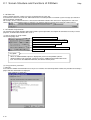
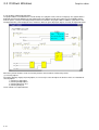
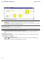
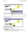
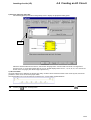
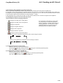
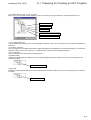
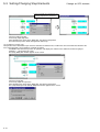
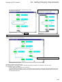
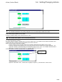
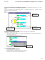
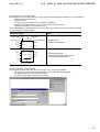
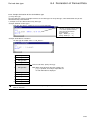
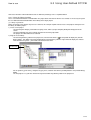
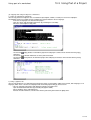
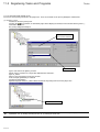
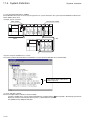
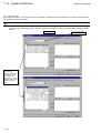
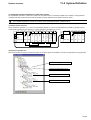
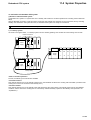
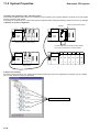
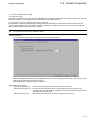
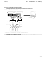
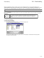
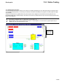
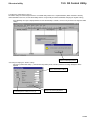
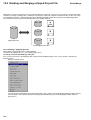
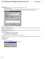
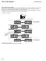
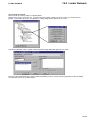
2) 1:N backup system
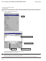
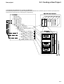
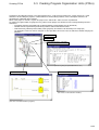
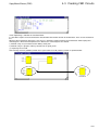
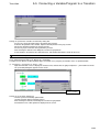
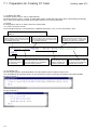
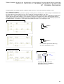
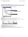
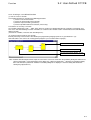
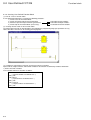
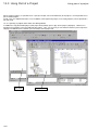
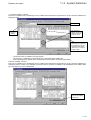
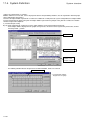
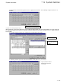
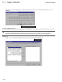
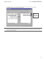
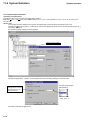
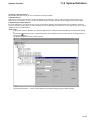
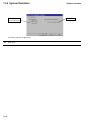
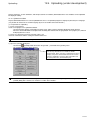
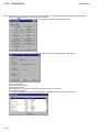
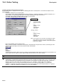
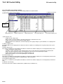
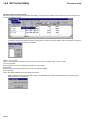
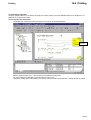
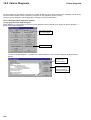
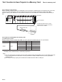
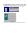
As shown in the figure below, with the “1:N backup system”, one standby CPU module and memory card interface module
(model: NP1F-MM1) performs back up for multiple working CPU modules.
Memory card interface module
Standby
IN
IN
Power
supply
OUT
CPU CPU CPU
0
1
2
OUT
Power
supply
CPU
5
Failure occurrence Working Working
The resources of CPU0 are automatically loaded
into CPU2 from the memory card and started.
IN
OUT
IN
Power
supply
CPU CPU
4
3
OUT
Power
supply
I/O
I/O
I/O
I/O
I/O
I/O
“1”
“2”
“3”
“4”
“5”
“6”
Working Working
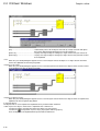
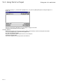
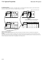
<How to continue operation>
Only the cold-start method is available. (The data of the working CPU module cannot be continued in the standby CPU
module.)
If a working CPU module has failed, the standby CPU module loads the resources (programs and system definitions) of the
failed CPU module from the memory card inserted in its memory card interface module to perform a cold-start. (The resources
of all the working CPU modules need to be registered in the memory card.)
11-40