1
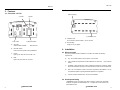
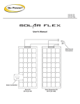
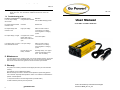
Go Power! Modifie
al
GP-175
as short as possible and twist them together with about 2 to 3
twists per foot. This minimizes radiated interference from the
cables.
GP-175
7.2 Troubleshooting guide
Problem and Symptoms
Low AC output voltage
95-105 VAC.
Possible Cause
Solution
Using standard voltmeter. Use true RMS averaging meter.
No output voltage and LED
indicator is red.
Overload.
Reduce load.
No output voltage, LED
indicator is red.
High input voltage.
Make sure that inverter is
connected to 12 V battery.
Check regulation of charging
system.
No output voltage, no lights.
Car lighter fuse, Inverter
lighter cable fuse or
interconnect cable fuse
open.
Check and replace.
Low battery alarm on all the Low input voltage.
time, LED indicator is red.
Poor DC wiring, poor
battery condition.
User Manual
300 watt Power Inverter
Make sure that inverter is
connected to 12 V battery.
Check regulation of charging
system.
Recharge battery. Use proper
cable and make solid connections. Use new battery.
8. Maintenance
Very little maintenance is required to keep your inverter operating properly. You should
clean the exterior of the unit periodically with a dry cloth to prevent accumulation of
dust and dirt. At the same time, tighten the screws on the DC input terminals.
9. Warranty
8
We
product by
against
defects
in materials (Go
and Power!)
workmanship
for astandard
period of 12
Thiswarrant
productthis
is covered
Carmanah
Technologies
12 month
months from the date of purchase and will repair or replace any defective Go Power!
warranty.
Inverter when directly returned, postage prepaid, to the manufacturer. This warranty will
Visitconsidered
gpelectric.com
additional
be
void for
if the
unit hasinformation.
suffered any obvious physical damage or alteration
Beforeinternally
contacting
Go Power!’s
customer
department,
please
gpelectric.
either
or externally,
and
does notservice
cover damage
arising
fromvisit
improper
use such
as
plugging
unit into anasked
unsuitable
powersection
sources,
attempting
to troubleshoot
operate products
com
to read the
the “frequently
questions”
of our
website to
the
with excessive power consumption requirements, reverse polarity, or use in unsuitable
problem. If trouble persists:
climates.
1. Call your Go Power!™ Technical Support team (1-866-247-6527)
2. Return
product and
to place
purchase.
This
is thedefective
only warranty
the of
company
makes no other warranties, express or
implied, including warranties of merchantability and fitness for a particular purpose.
Repair or replacement are your sole remedies and shall not be liable for damages,
whether direct, incidental, special or consequential, even though caused by negligence
or other fault.
gp electric.com
m
© 2014 Go Power! By Carmanah Technologies
Document: MAN_GP-175_vB
Go Power! Modified Sine
al
GP-175
GP-175
6.2 Overload
Table of Contents
1. INTRODUCTION
3
2. SPECIFICATIONS
3
3. FEATURES
4
4. INSTALLATION
5
5. OPERATION
6
6. OPERATING LIMITS
8
7. TROUBLESHOOTING
7
8. MAINTENANCE
8
9. WARRANTY
8
The fault LED will come on when the power inverter has shut itself down because
its output circuit has been short-circuited or drastically overloaded. Switch the ON/
OFF switch to OFF, correct the fault condition, and then switch the ON/OFF switch
back to ON.
Some induction motors used in refrigerators, freezers, pumps and other motor operated equipment require very high surge currents to start. The power inverter may not
be able to start some of these motors, even though their rated current draw is within
the power inverter.
If the motor refuses to start, observe the battery voltage indicator while trying to
start the motor. If the battery voltage indicator drops below 11 volts while the
inverter is attempting to start the motor, this may be why the motor will not start.
Make sure that the battery connections are good and that the battery is fully
charged. If the connections are good and the battery is charged, but the voltage still
drops below 11 volts, you may need to use a larger battery.
6.3 Input voltage
The power inverter will operate from input voltage ranging 10 V – 15 V. If the voltage
drops below 10.7 V, an audible low battery warning will sound and the fault LED will be
on. The power inverter will shut down if the input voltage drops below 10 V. This
protects your battery from being over discharged.
The power inverter will also shut down if the input voltage exceeds 15 V. This protects
the inverter against excessive input voltage. Although the power inverter incorporates
protection against over voltage, it may still be damaged if the input voltage is allowed to
exceed 20 V.
Go Power! Electric Inc.
PO Box 6033
Victoria, BC V8P 5L4
Toll Free Tel: 866-247-6527
Toll Free Fax: 866-607-6527
Email:
7.
Troubleshooting
7.1 Common problems
a) Buzz in audio systems
Some inexpensive stereo systems will emit a buzzing noise from their loud speak
ers when operated from the power inverter. This is because the power supply in
the device does not adequately filter the modified sine wave produced by the
power inverter. The only solution is to use a sound system that incorporates a
higher quality power supply.
b) Television interference
Operation of the power inverter can interfere with television reception on some
channels. If this situation occurs, the following steps may help to alleviate the
problem.
• Do not operate high power loads with the power inverter
while watching television.
• Make sure that the antenna feeding your television provides
an adequate (“snow free”) signal and that you are using good
quality cable between the antenna and the television.
• Move the television as far away from the power inverter as
possible.
• Keep the cables between the battery and the power inverter
2
gp electric.com
gp electric.com
7
Go Powe
al
GP-175
GP-175
Caution
Do not connect this inverter and another AC source (generator or utility power) to the
AC wiring or AC loads at the same time. Doing so will destroy the inverter and void
the warranty, regardless whether the inverter is switched on or off. If you are using
more than one AC source for the AC wiring or AC loads, it is highly recommended that
you install an automatic transfer switch (GP-TS), available from Go-Power Electric
Inc.
Please consult your automobile owners manual for the fuse rating of your lighter. It is
recommended that you DO NOT exceed a load of 100 watts for a 10 Amp fuse and 140
Watts for a 15 amp fuse when using your car lighter to power this inverter.
To hook-up please follow these guidelines:
1. Unpack and inspect your Go Power! Inverter, check to see that the power switch
is in the OFF position.
2. Insert DC input plug into any 12 V DC car lighter receptacle.
3. Set the power switch to the ON position. The power status LED should be green.
4. Set the power inverter switch to the OFF position. The indicator lights may blink and
the internal alarm may sound momentarily. This is normal. Plug the test load into the
AC receptacle on the front panel of the inverter. Leave the test load switch OFF.
5. Set the power inverter switch to the ON position and turn the test load on; the
inverter should supply power to the load. If you plan to measure the output voltage
of the inverter, a true rms meter must be used for accurate readings.
5. Operation
To operate the power inverter, turn it on using the ON/OFF switch on the front panel.
The power inverter is now ready to deliver AC power to your loads. If you are operating
several loads from the power inverter, turn them on separately after the inverter has
been turned ON. This will ensure that the power inverter does not have to deliver the
starting currents for all the loads at once.
5.1 Controls and indicators
The ON/OFF switch turns the control circuit in the power inverter ON and OFF. It
does not disconnect power from the power inverter.
1. Introduction
The Go Power! Inverter series provides mobile power for people on the go. Run
standard AC appliances wherever you travel. Silent, lightweight and simple to use, Go
Power! Inverters can be used in a wide range of applications including remote homes,
RVs, boats and long haul trucks. It will operate most televisions and VCR’s, personal
computers and small appliances including drills, sanders, grinders, mixers, blenders
and microwaves. The inverter must have a greater power rating than the load to
which it is providing power.
To get the most out of your power inverter, it must be installed and used properly.
Please read the instructions in this manual before installing and using your
inverter.
2. Specifications
2.1 GP-175 Inverter
Output
Output wave form
Output voltage
Regulation
DC input voltage
Low battery alarm ± 2%
Low battery shut-down ±2%
Efficiency
Frequency ±1%
No load current
Surge rating
Over thermal protection
Cooling fan
Overload protection
Dimensions (LxWxH)
Net weight
Inverter Install Kit
12V
175 W
Modified Sine Wave
115 VAC rms
+5%-10%
10-15 V
10.5 V
10.0 V
80-90%
60 Hz
0.2 A
210 W
Yes
No
Yes
125 x 82 x 45 mm
5” x 3.25” x 1.8”
0.5 kg
1.1 lbs
Included
When the switch is in the OFF position, the power inverter draws no current from
the battery. When the switch is in the ON position but with no load, the power idle
current is approximately 1 A (see product specifications for exact current draw).
6. Operating limits
6.1 Overtemp
The fault LED will come on when the inverter has shut itself down because the inverter
has become overheated. The power inverter may overheat because it has been
operated at power levels above it’s rating, or because it has been installed in a location
that does not allow it to dissipate heat properly. The power inverter will restart automatically once it has cooled off.
6
gp electric.com
gp electric.com
3
GP-175
GP-175
3.1 Rear view – GP-175
3. Features
3.1 Front view – GP-175
b) DC input plug
d) Fault
c) Power
a) AC outlet
a)
b) ON/ OFF switch
AC outlet:
Outlet sockets available:
a) Ventilation port
a) Ventilation port:
Do not obstruct, allow at least 1 inch for air flow.
b) DC input plug:
Plugs into any car lighter.
North America
b)
ON/ OFF switch:
Leave in the OFF position during installation.
c)
Power:
Lights green when GP-175 inverter is on.
d)
Fault:
Lights red when fault has occurred.
4. Installation
4.1 Where to install
The power inverter should be installed in a location that meets the following
requirements:
a)
Dry - Do not allow water to drip or splash on the inverter.
b)
Cool - Ambient air temperature should be between 0°C and 40°C
better).
c)
Ventilated - Allow at least two inches of clearance around the inverter for airflow.
Ensure the ventilation openings on the rear and bottom of the unit are not obstructed.
d)
Safe - Do not install the inverter in the same compartment as batteries or in any
compartment capable of igniting flammable liquids such as gasoline.
e)
Inverter should be located within 10 feet of the batteries.
(the cooler the
4.2 Hook-up and testing
* Important: The DC car lighter input cable includes a 15 Amp fuse. Most North
American car lighters are rated between 10 - 15 Amps DC and are fused in the
automobile fuse box.
4
gp electric.com
gp electric.com
5