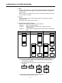
1
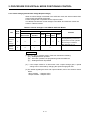
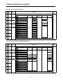
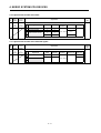
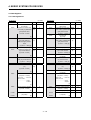
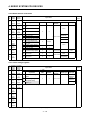
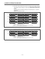
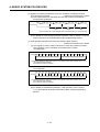
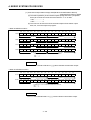
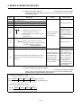
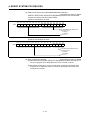
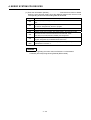
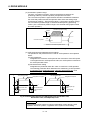
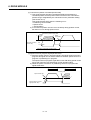
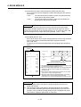
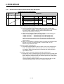
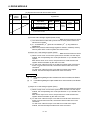
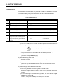
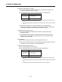
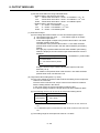
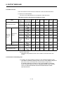
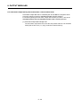
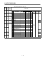
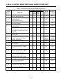
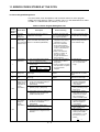
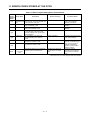
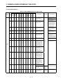
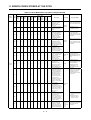
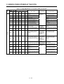
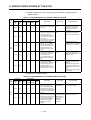
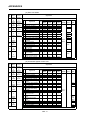
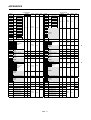
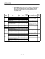
11. ERROR CODES STORED AT THE PCPU
(5) Output module errors at VIRTUAL servo mode axis START (10000 to 10990)
Table 11.4 Output Module Error List (10000 to 10990) (Continued)
Error
Class
Error Code
Output Drive
Modu- Module
le
Output Module
Roller
Ball
Screw
Rotary
Table
Error Cause
Cam
• The home position return
request (M1609 + 20n) is ON.
10000
1000[ ]
10010
1001[ ]
10020
1002[ ]
!
!
!
!
!
!
!
!
!
!
!
Major
Errors
10030
1003[ ]
!
!
!
!
Processing
START disabled
at related
systems.
• The servo error detection
signal (M1608 + 20n) is ON.
• A servo OFF (M1615 + 20n
ON) status exists at an output
module where a "clutch ON" or
"no clutch" setting is
designated at either the main
shaft or auxiliary input shaft.
• An external input signal
(STOP) is ON at an output
module where a "clutch ON" or
"no clutch" setting is
designated at either the main
shaft or auxiliary input shaft.
Corrective Action
• Return to the REAL mode and
execute a home position
return.
• If position is not established
after executing a home position
return at all axes, VIRTUAL
mode operation will be
disabled.
• Execute a servo error reset in
the REAL mode.
• Switch the clutch OFF, then
establish the servo ON status.
• Switch the stop signal (STOP)
OFF.
(6) "No-clutch/clutch ON/clutch status ON" output module errors (11000 to 11990)
Table 11.4 Output Module Error List (11000 to 11990) (Continued)
Error
Class
Error Code
Output Drive
Modu- Module
le
11000
1100[ ]
Output Module
Roller
!
Ball
Screw
!
Rotary
Table
!
Error Cause
Cam
!
• The servo error detection
signal (M1608+20n) switched
ON during operation.
•
11010
1101[ ]
!
!
!
!
•
Major
Errors
11020
1102[ ]
!
!
!
!
•
•
11030
1103[ ]
!
!
!
!
•
11040
1104[ ]
!
!
!
!
Processing
Corrective Action
After an
• Eliminate the servo error cause
immediate stop at
(see section 11.4).
the relevant
output module,
the servo will be
switched OFF.
• When an "operation
A servo OFF status
• Operation
continuation" setting is
(M1615+20n ON) occurred
continues at
designated, execute stop
during operation.
"no-clutch"
processing at the user's
MR-[ ]-B power supply was
axes.
sequence program.
interrupted.
• At axes with
clutches,
The stop signal (STOP)
control is
switched ON.
executed in
The upper limit LS signal
accordance with
(FLS) switched OFF during
the operation
forward (address increase
mode at the
direction) travel.
time of the
The lower limit LS signal (RLS)
error.
switched OFF during reverse
• Operation
(address decrease direction)
continues.
travel.
• All clutches
switch OFF at
the relevant
systems.
11 − 26