1
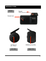
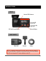
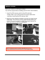
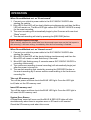
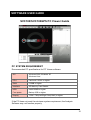
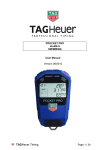
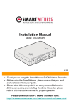
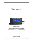
SVC100 / SVC100GPS! VEHICLE JOURNEY RECORDER! USER GUIDE Thank you for purchasing this Journey Recorder. Please ensure that you read and understand this USER GUIDE and use it before connecting and installing this Recorder. Please store the USER GUIDE in an easily accessible location. VER 2.0.0 2nd Edition SAFETY ADVICE CAUTION RISK OF ELECTRIC SHOCK DO NOT OPEN CAUTION: TO REDUCE THE RISK OF ELECTRIC SHOCK, DO NOT REMOVE COVER. NO USER-SERVICEABLE PARTS INSIDE. REFER SERVICING TO QUALIFIED SERVICE PERSONNEL. Please make sure you follow the safety advice/instructions given in the user guide. Caution RISK OF EXPLOSION IF BATTERY IS REPLACED BY AN INCORRECT TYPE. DISPOSE OF USED BATTERIES ACCORDING TO THE INSTRUCTIONS. Battery for RTC(Real Time Clock) inside Caution Connect your vehicle’s power cable (cigarette jack) to the product after starting the vehicle. The instant over voltage generated when starting up the vehicle may damage the product if it is already connected. Caution Install the product where it does not block driver’s visibility and where there is no airbag installed. This could cause an accident or might injure passengers in case of accident Caution Damages due to production malfunction, loss of data, or other damages occurring while using this product shall not be the responsibility of the manufacturer. Although the product is a device used for recording videos, the product may not save all videos in the case of a malfunction. In the case of an accident, the sensor may not recognize the shock when the impact is light and as a result it may not begin recording automatically. WARNING: TO PREVENT FIRE OR ELECTRIC SHOCK HAZARD, DO NOT EXPOSE THIS APPLIANCE TO RAIN OR MOISTURE. 3 GPS Reception 1. Activate the product in an area without large buildings to improve GPS reception. The commercial purpose GPS has the average rage error of more than 15 meters and the range error could be more than 100 meters due to environmental conditions like buildings, roadside trees etc. 2. The temperature range for optimum operation of the GPS receiver in your car is -10 ~ 50°C. 1. When using the product for the first time or after a long period (more than three days), it may take a little longer to recognize your current location. It may take between five and thirty minutes to get GPS reception. GPS reception may be impaired under the following circumstances 1) If there is an object at the end of the GPS antenna 2) If your vehicle has metallic elements on the windshields 3) If equipment generating electromagnetic waves that interfere with the GPS signal is installed in the vehicle e.g.: Other GPS devices such as a certain type of wireless activated alarms, MP3 and CD players and camera alarms using GPS. 4) If you are using a receiver connected by cable, electric interference can be avoided by simply changing the location of the receiver (antenna). 5) On heavily overcast or cloudy days, if the vehicle is in a covered location such as under a bridge or raised roadway, in a tunnel, an underground roadway or parking area, inside a building or surrounded by high-rise buildings. 6) If GPS signal reception is poor, it may take longer to locate your current position when the vehicle is moving than when it is stationary. 4 CONTENTS Smart Witness SVC100 / SVC100GPS Camera/Recording Unit including bracket 2GB SD memory card (The Analysis Software is on the provided SD card) Power Cable (cigarette jack) USB 2.0 SD Card Reader Spare camera mounting components a. Wire Splice clips (x5) b. c Includes: a. 5x Wire Splice clips b. 1x Sticker for Windscreen mounting c. 1x Camera bracket Sticker for Windscreen mounting (double sided tape x1) 5 INTRODUCTION FRONT Bracket Adhere tape on bracket Camera Lens DC Power In (DC 12~24V) Left side SD Memory Card Slot Right Side 6 INTODUCTION BACK Internal GPS Antenna Record LED BLUE LED Overwrite LED RED LED SD Card Format Button Record Button UNIT PARTS Main Unit Bracket Holder NOTE: Formatting [initializing] SD memory card can be done using SD Card Format Button. However we recommend that you format [initialize] the SD card using the PC Viewer software on the PC. 7 INSTALLATION Park your vehicle on a flat level surface. Turn off the engine before installing the SVC100 / SVC100GPS. 1. Insert the SD memory card into the SD card slot. Please make sure to disconnect the power cable when inserting or ejecting the SD memory card. 2. Attach the SVC100/SVC100GPS using the provided double sided tape. The surface must be clean and dry before you install. We recommended to install the product behind the rear view mirror on the front windshield. NOTE: Adhesive tape will not stick well with dust or oil, etc. Warm temperatures are best (above 60°) when applying tape. 8 INSTALLATION 3. Adjust camera view. Make sure the lens has an unobstructed view. Check from outside the vehicle to check the camera angle. Arrange the power cord neatly alongside the windshield and door pillar trim. Use the provided wire splice clip as seen in the picture on left. 4. SVC100/SVC100GPS unit requires a continuous 12-24V DC power source from the vehicle. Plug in the power. The provided power cord cable route should be from the left side of the SVC100/SVC100GPS towards your power source. NOTE: When the impact is light like a minor bump in the road, the G-sensor may not recognize the impact and as a result it may not begin recording automatically. Test and set your own G-sensor level for your vehicle. 9 FUNCTION Automatic start Connect your vehicle’s power cable to the SVC100 / SVC100GPS after starting the vehicle. Then SVC100 / SVC100GPS will be automatically started. (Use the provided power cable.) NOTE: The unit will not start recording immediately after power on. It takes around 1 minute for the built-in power backup system to charge. Thereafter, the internal flash memory will be ready to record. Event record (when Record Method set as “Event record”) The event recording will be automatically started by G-sensor. G-sensor sensitivity can be set with your PC. Each event file contains 15 seconds prior & 5 seconds post event. Manual record (when Record Method set as “Event record”) Press the [RECORD] button to begin recording manually. Each manual file contains 15 seconds prior to activation & 5 seconds post activation. Continuous record (when Record Method set as “Normal record”) The continuous recording will be automatically started after power on. SVC100/SVC100GPS doesn’t make a separate event file during the continuous recording . It will mark the Event area by the G-sensor or Record button in the continuous recording file which can be easily searched for during playback. SD Memory Card Format Remove the power first. Press the SD CARD FORMAT button and hold. Then connect the power for initialisation. Once complete, all video & log files will be deleted and the configurations will default to the factory settings. NOTE: PC Viewer software is pre-loaded on the SD card. Please ensure you have installed the software to your PC before you format the card Built-in power backup (Super Capacitor) When power to the unit is interrupted, SVC100/SVC100GPS creates the last file using the internal Super Capacitor. BLUE LED (RECORD) The blue LED shows the power is on. The blue LED flash during recording. RED LED (OVERWRITE) The red LED will be turned on during overwriting. Buzzer A ‘Beep’ sound will occur when recording starts (this can be turned off if required) and to signal a system error. 10 OPERATION When Record Method set as “Event record” 1. Connect your vehicle’s power cable to the SVC100/SVC100GPS after starting the vehicle. 2. Blue LED & Red LED will be slowly blinking simultaneously and then the Blue LED will remain on. The Blue LED light means SVC100/SVC100GPS is ready for the event recording. 3. The event recording will automatically begin by the G-sensor with one short “Beep” sound. 4. The manual recording will start by pressing the [RECORD] button. NOTE: Multiple impacts coverage Flash memory captures the video data from the second impact even as the first impact is still occurring. It will start writing, immediately after the first recording is finished. When Record Method set as “Normal record” 1. Connect your vehicle’s power cable to the SVC100/SVC100GPS after starting the vehicle. 2. Blue LED & Red LED will be slowly blinking simultaneously and then the Blue LED will remain on and flash every 5 seconds. 3. Blue LED light flashing every 5 seconds means SVC100/SVC100GPS is recording continuously. 4. The continuous recording (normal recording) will automatically begin just after the power is turned on. 5. The manual recording that started by pressing the [RECORD] button or the event recording by G-sensor make a event making in the continuous recording file. Take out SD memory card Turn off the power and then check the BLUE LED light. Once the LED light is off, take out the SD memory card. Insert SD memory card Turn off the power and then check the BLUE LED light. Once the LED light is off, insert the SD memory card. System Error Buzzer A ‘Beep Beep’ sound will occur and the BLUE & RED LED lights will blink simultaneously when there is a system error or SD card is not inserted. Check the SD memory card when this occurs. 11 SOFTWARE USER GUIDE SVC100/SVC100GPS PC Viewer Guide PC SYSTEM REQUIREMENT Recommended PC specifications for PC Viewer software OS Windows 2000, Windows XP Windows Vista CPU Pentium4 2.6GHz or higher RAM 512MB or higher Interface SD Memory Card Reader HDD Free space Install 20MB or higher Backup 2GB or higher Display 1,024 x 768 pixel/High Color(16bit) or higher If the PC does not meet the minimum system requirement, the Analysis Software may not function properly. 12 SOFTWARE INSTALLATION PC Viewer software is on the provided SD card. 1. Connect the SD card into your PC (if your computer does not have and SD card slot use the USB SD card reader) and open the “My Computer” 2. Right-click the “DRIVEREC1” drive and select [Open] 3. Double click [SETUP.EXE] at [pcsw] folder. 4. Select the language and then follow the dialog box. 5. The “PCViewer” icon will be displayed on your desktop. NOTE: To Un-install the PC Viewer Open the ‘Control Panel’ Select ‘Remove Program’ and remove Smart Witness Analysis Software. 13 Connect SD memory card 1. Connect SD memory card into the SD card reader. 2. Run “SmartWitness” 3. Select [File] and then click “Select Data Folder” or Click [OPEN] button [OPEN] button 4. Select SD memory card folder at the folder select window. 14 PC Viewer Setting This setting is for the PC Viewer itself. To set the Recorder, refer to page 27. The ‘date’ formats and ‘speed’ unit will be set automatically according to the PC Windows setting. However it can be changed with this PC viewer setting menu. Normal Video Left/right flip Up/down flip 15 Select file for playback When Record Method set as “Event record” Check the event “G-Senor” means recording was activated by impact “Switch” means recording was activated by button Check all files Button Load Button When Record Method set as “Normal record” Check the file Check all files Button Recording duration The maximum duration is 10 minutes Load Button 5. Check the event or normal recorded file from the list using mouse or click [All] button. Then click [Load] button. 15 FILE LOADING 6. Click the [Load] button once, the [FileList] tab will be changed to the [PlayList] tab as shown below When Record Method set as “Event record” Now playback this file Return to the [FileList] Check it for the continuous playback When Record Method set as “Normal record” Now playback this file Check it for the continuous playback Return to the [FileList] Event data search in the playback file 16 PLAYBACK SCREEN When Record Method set as “Event record” [POST]: post-recorded frame [PRE]: pre-recorded frame Check it for continuous playback Display frame/Total frames number Frame size When Record Method set as “Normal record” Event area marking by G-sensor or button (5seconds per each event) Google Map location data only available with SVC100GPS model Playback position indicator 17 PLAYBACK 7. Click play button for playback. Playback speed GPS Speed, G sensor data & GPS location data Date & Time Drag & Move the white bar to move the playback position. Before 15seconds After 5sec Event Playback buttons X2, 4, 8, 16 Fast Reverse X0.5, 1 Reverse Previous Image X0.5, 1 Play Pause X2, 4, 8, 16 Fast Forward Next Image Single View 4x4 Multi View (Thumb-nail function) Zoom In G-sensor graph Reset Zoom Zoom Out G-sensor graph 18 PLAYBACK NOTE: PC Keyboard hot buttons Function PC keyboard hot buttons 1024x768 mode Enter Return to the previous mode: Enter Full screen mode Alt + Enter Return to the previous mode: Enter Playback speed control Ctrl + F 0.5 => 1 Reverse playback speed control Ctrl + B 0.5 => 1 Pause / Play Space Previous Image → direction button. Next Image ← direction button 19 Google map (Supported by the SVC100GPS model only) The route taken will be displayed on the Google map at lower right corner of the software. To see the route & position on Google Maps, the GPS data should be recorded with video. To see Google Maps, the PC should be connected to the Internet. The Playback position will be shown on the map with an arrow. The blue markings show the route taken. Zoom Out Double click the blue mark to change the video playback position to that point. The camera icon indicates that there is a recorded file. The total camera icons Shown will be less than 100, even If there are more than 100 events When the unit is set To ‘Normal’ recording mode, there will be No route & camera Icon on the map. 20 Thumbnail Function 7. Click the button for 4x4 multi view (Thumbnail function) Click the thumbnail image to change the playback position. Click right the mouse button to single image playback mode. 8. Click [Close] button to quit the playback. Click [Close] to finish the playback. Then the [PlayList] window will be changed to the initial status. 21 Save JPG file & AVI file 9. Pause the playback and click ‘Save Image’ icon to make a JPG file. ‘Save Image’ icon 10. Click ‘Save AVI’ icon to make a AVI file. ‘Save AVI’ icon 22 Print image 11. Pause the playback and click ‘Print Image’ icon. Print image icon Type in the File Name [Print Title] & any comments [Print Comment] using the Keyboard. The ‘Print Comment’ window allows up to 7 lines total. 23 Make Report 12. Click [Print] button in the print preview windows for printing. The File Name [Print Title], Comment [Print Comment], G-sensor graph & map (for SVC100GPS Model only) will be printed on the first page. Click [ 2x2 ] and then click [Print] to print 4 images in one page. 24 Backup Event/Log files 13. Click [Backup Event/Log files] icon to backup the files to the PC. [Backup Event/Log files] icon Select [Event data] or [Normal data] and select [Log data] first, before clicking the [Backup Event/Log files] icon. Then selected Event or Normal or Log data list are on the Backup windows. To backup the whole data from SD card to the PC, check [Backup All] 25 Setting the Vehicle Journey Recorder 14. Click [Recorder Setting] icon for setup. [Recorder Setting] icon Caution Backup the SD data first, before clicking initialize SD card button. Once done, the old data cannot be recovered. . Recording Method Event Record (Automatically starts Recording by G-sensor event or Record Button) Normal Record (Automatically starts continuous Recording just after Power on) Image Resolution 640x480(High), 320x240(Low) Frame Rate ‘30’ fps means Real Time recording Event Record supports 10, 15, 30 fps Normal Record supports 1, 5, 10, 15 fps Image Quality High (Large file size, but good picture quality) Low (Small file size, but low picture quality) Event Record Time This menu is for Event Record. Pre-record/Post-record time can be set here. There are 3 options (10/10, 12/8, 15/5) Recording Mode Overwrite (The image data is overwrites the oldest files when the SD memory is full.) One time (The recording stops automatically when the SD memory is full.) 26 Setting the Vehicle Journey Recorder Beep on record “Beep” sound ON/OFF when Event recording start G-sensor setting Check simple setting mode and then change the sensitivity. High sensitivity like 8 or 9 means recording will be started at very low impact. Date/Time Automatically synchronize with GPS time. However Manual time setting is also available. Vehicle ID Type in your Vehicle ID Initialize SD card All date will be deleted and set the configuration of the Journey Recorder will default to the factory settings. Initialize Data All date will be deleted. Caution Once the record setting was changed, all recorded data in SD card will be removed automatically. Select Backup [YES] or [NO] before lost the all recorded data. 27 Setting the Vehicle Journey Recorder G-Sensor setting If G-sensor sensitivity value is too high like 8 or 9, it becomes too sensitive, so it will detect even a light impact or light turn. If G-sensor sensitivity value is too dull, so it might not detect a notable incident. So, sensitivity should be set in consideration of the vehicle’s suspension and condition and also the road condition. [SVC100] doesn’t have the GPS time sync. function, so please click the manual time setting, and set your time before installing it in your car. [SVC100GPS] have the internal GPS supporting the automatic GPS Time Synchronize function. The time recording is done based on UTC at the SVC100GPS and automatically converts to the local time at the PC according to the PC time zone setting when playing back using the PC Viewer. NEW SD Memory card initializing should be done using Tool menu . STEP1. Insert new SD memory card into the PC. STEP2. Run “PC Viewer SVC100” STEP3. Select [Tool] and then click [SD Initialize] We recommend the [SD initialize] at least once per month to prevent the SVC100/SV C100GPS from any software errors. 28 Product Information 15. Click [About] icon to check the product information. About icon 29 LOG FILE PLAYBACK 16. Select [LOG] windows and then check the log from the log list using mouse or click [Check All] button. Then click [Load] button. Log data Log data will be recorded during driving even if there are no events. The total log data size is no more than 60MB. The log data overwrites t he oldest data when 60MB is reached. Using this log data, we can use the dat a sorting function which helps to find a specific data like more than 80mph(or 8 0km), for example. Search button Input sorting data G-sensor graph GPS speed, G sensor X value, G sensor Y value, G sensor Z value, can be checked first on the small check box at right side of each value. Then input data for data sorting. If there is recorded video data, [Switch] or [G Sensor] mark will be displayed on list. G sensor X value: Front & Back (like Quick brake or Quick Start) G sensor Y value: Left & Right (like Quick Turn) G sensor Z value: Up & Down (like prominence and depression) 30 GPS LOG TO KML CONVERTER (for Google Earth) To see the whole route on Google Earth, select the log file and click Google Earth button. (SVC100GPS only) STEP1. Install the Google Earth on your PC. (http://earth.google.com/ ) STEP2. Check the log file STEP3. Click Google Earth button The route will then be shown on Google Earth. We recommend you use Google Earth Version 5.0 or above. Tip: Click [Car Track] and then Click [Play Tour] button 31 SPECIFICATION Image sensor 1/4" CMOS DSP Standard DSP Angle of View 170° Video resolution 640x480, 320x240 Recording Speed Up to 25 fps Recording Modes Continuous By impact By emergency button. Recording time 2GB (37minutes~ 36hours) 16GB (7hours~167hours) Backup SD Memory Card Memory 2GB SD memory card (supports SDHC cards of up to 32GB) GPS Internal GPS (SVC100GPS only) G-Sensor Internal 3-axis G-sensor RTC Internal battery Buzzer Recording start, error LED 2 LED (Record, Overwrite) Supper Capacitor Enable recording of last file and shut down PC software Supplied Power input 12V to 24V DC (cigarette plug) Power consumption 3.6W Size (LxØ)/Weight 80mm X 50mm , 100g Operation Temp. -10℃~50℃ 32 Recording time table Resolution Quality Size HIGH 40KB 640x480 LOW 20KB HIGH 15KB 320X240 LOW 10KB FPS 2GB 4GB 8GB 1 555 min 1408 min 3115 min 5 111 min 282 min 623 min 10 55 min 141 min 311 min 15 37 min 94 min 208 min 1 1109 min 2816 min 6229 min 5 222 min 563 min 1246 min 10 111 min 282 min 623 min 15 74 min 188 min 415 min 1 1479 min 3755 min 8306 min 5 296 min 751 min 1661 min 10 148 min 375 min 831 min 15 99 min 250 min 554 min 1 2219 min 5632 min 10000 min 5 444 min 1126 min 2492 min 10 222 min 563 min 1246 min 15 148 min 375 min 831 min 16GB 109 hours 22 hours 11 hours 7 hours 167 hours 44 hours 22 hours 15 hours 167 hours 58 hours 29 hours 19 hours 167 hours 87 hours 44 hours 29 hours NOTE: Limitation of the event file number The total recording file number will be less than 1000. If the unit records more than 1000 files, there is a possibility that the booting time will be more than 1 minute. Therefore, the number of files are limited to a maximum of 1000. So the maximum recording time is 167 hours. 1000 files x 10 minutes = 10000 minutes = 167 hours 33 Technical Support & Warranty TECHNICAL SUPPORT For Technical Support, please contact your local distributor. LIMITED WARRANTY This product is supplied with 1 year warranty. The Warranty excludes products That have been misused, (including accidental damage) and damage caused by normal wear and tear. In the unlikely event that you encounter a problem with this product, it should be returned to the place of purchase. 34 Optional Accessory (Permanent Power Cable) Model name: SVC100PPC The Permanent Power Supply Cable will allow you to hard wire the SVC100/ SVC100GPS unit to the fuse box of your vehicle. ① Recorder ② Fuse box (+) Fuse: 250V 1A ③ Ground The ground cable should be contacted at the car body. Connect (+) to the reserve Fuse. It should be connected to the power that is on when start the engine. 35 APPENDIX (Upgrade) NOTE: To get the upgrade firmware, please contact your local distributor. 1. Prepare Firmware Make a [program] folder on the SD root folder as shown below, Copy “SVC100_X.X.X.bin” file to the SD card [program] folder. 2. Upgrade SVC100/SVC100GPS Insert the prepared SD card to SVC100/SVC100GPS unit and turn on the power. The Blue & Red LED will quickly blink while the unit is upgrading. It will also ‘beep’ continuously. Upgrading the unit usually takes about 2 to 3 minutes. Warning: Do not turn off the power during upgrading. If the upgrade fails, the SVC100/SVC100GPS unit should be returned to your local distributor. Once the upgrading is finished, turn off the power. 36 APPENDIX (Upgrade) 3. Check SVC100/SVC100GPS Turn on the SVC100/SVC100GPS and press the [RECORD] button to check the unit is recording properly. If the SVC100/SVC100GPS records as normal, turn off the power. Insert the SD card into your PC and initialise it using the software once you have successfully tested the SVC100/SVC100GPS. To initialise the SD card. Run the ‘SmartWitness’ software and select [Tool] > [SD initialize] Select the SD card Drive and click OK 37 APPENDIX (Upgrade SVC100/SVC100GPS) 4. Uninstall the old version of PC Viewer from your PC PC Windows [Start] > [Control panel] And uninstall [SmartWitness] 5. Install the new PC Viewer Run setup.exe and install the new SmartWitness X.X.X.X Click “OK” and check [Quick Format] and un-check [Backup configuration file] as below, NOTE: After installation the new PC Viewer, initialise the SD card. The new software will automatically be copied to [pcsw] folder on the SD card. 4/7 Manufactured exclusively for:! www.smartwitness.com! Smart Witness is a Division of Xvision!