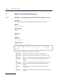
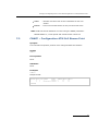
1
Dialogic ® DSI Signaling Servers User Manual Supplement for ATM Operation www.dialogic.com Copyright and Legal Notice Copyright© 2009 Dialogic Corporation. All Rights Reserved. You may not reproduce this document in whole or in part without permission in writing from Dialogic Corporation at the address provided below. All contents of this document are furnished for informational use only and are subject to change without notice and do not represent a commitment on the part of Dialogic Corporation or its subsidiaries (“Dialogic”). Reasonable effort is made to ensure the accuracy of the information contained in the document. However, Dialogic does not warrant the accuracy of this information and cannot accept responsibility for errors, inaccuracies or omissions that may be contained in this document. INFORMATION IN THIS DOCUMENT IS PROVIDED IN CONNECTION WITH DIALOGIC ® PRODUCTS. NO LICENSE, EXPRESS OR IMPLIED, BY ESTOPPEL OR OTHERWISE, TO ANY INTELLECTUAL PROPERTY RIGHTS IS GRANTED BY THIS DOCUMENT. EXCEPT AS PROVIDED IN A SIGNED AGREEMENT BETWEEN YOU AND DIALOGIC, DIALOGIC ASSUMES NO LIABILITY WHATSOEVER, AND DIALOGIC DISCLAIMS ANY EXPRESS OR IMPLIED WARRANTY, RELATING TO SALE AND/OR USE OF DIALOGIC PRODUCTS INCLUDING LIABILITY OR WARRANTIES RELATING TO FITNESS FOR A PARTICULAR PURPOSE, MERCHANTABILITY, OR INFRINGEMENT OF ANY INTELLECTUAL PROPERTY RIGHT OF A THIRD PARTY. Dialogic products are not intended for use in medical, life saving, life sustaining, critical control or safety systems, or in nuclear facility applications. Due to differing national regulations and approval requirements, certain Dialogic products may be suitable for use only in specific countries, and thus may not function properly in other countries. You are responsible for ensuring that your use of such products occurs only in the countries where such use is suitable. For information on specific products, contact Dialogic Corporation at the a ddress indicated below or on the web at www.dialogic.com. It is possible that the use or implementation of any one of the concepts, applications, or ideas described in this document, in marketing collateral produced by or on web pages maintained by Dialogic may infringe one or more patents or other intellectual property rights owned by third parties. Dialogic does not provide any intellectual property licenses with the sale of Dialogic products other than a license to use such product in accordance with intellectual property owned or validly licensed by Dialogic and no such licenses are provided except pursuant to a signed agreement with Dialogic. More detailed information about such intellectual property is available from Dialogic‟s legal department at 9800 Cavendish Blvd., 5th Floor, Montreal, Quebec, Canada H4M 2V9. Dialogic encourages all users of its products to procure all necessary intellectual property licenses required to implement any concepts or applications and does not condone or encourage any intellectual property infringement and disclaims any responsibility related thereto. These intellectual property licenses may differ from country to country and it is the responsibility of those who develop the concepts or applications to be aware of and comply with different national license requirements. Dialogic, Dialogic Pro, Brooktrout, Diva, Cantata, SnowShore, Eicon, Eicon Networks, NMS Communications, NMS (stylized), Eiconcard, SIPcontrol, Diva ISDN, TruFax, Exnet, EXS, SwitchKit, N20, Making Innovation Thrive, Connecting to Growth, Video is the New Voice, Fusion, Vision, PacketMedia, NaturalAccess, NaturalCallControl, NaturalConference, NaturalFax and Shiva, among others as well as related logos, are either registered trademarks or trademarks of Dialogic Corporation or its subsidiaries. Dialogic's trademarks may be used publicly only with permission from Dialogic. Such permission may only be granted by Dialogic‟s legal department at 9800 Cavendish Blvd., 5th Floor, Montreal, Quebec, Canada H4M 2V9. Any authorized use of Dialogic's trademarks will be subject to full respect of the trademark guidelines published by Dialogic from time to time and any use of Dialogic‟s trademarks requires proper acknowledgement. The names of actual companies and product mentioned herein are the trademarks of their respective owners. Publication Date: July 2009 Document Number: U01LFD, Issue 1 2 Dialogic® DSI Signaling Servers User Manual Supplement for ATM Operation Issue 1 Contents Revision History ........................................................................................................... 4 1 Introduction ........................................................................................................ 5 1.1 1.2 1.3 Overview ............................................................................................................................... 5 Applicability ........................................................................................................................... 5 Related Documentation............................................................................................................ 5 2 ATM Operation..................................................................................................... 6 3 Installation.......................................................................................................... 7 3.1 3.2 3.3 3.4 SS7MD SS7MD SS7MD SS7MD 4 Board Configuration .......................................................................................... 12 4.1 4.2 4.3 Network Interface Boards ...................................................................................................... 12 Line Interface Unit ................................................................................................................ 12 Cross Connect Configuration .................................................................................................. 13 5 Signaling Configuration ..................................................................................... 14 5.1 5.1.1 5.1.2 5.1.3 5.1.4 5.2 5.2.1 5.2.2 ATM Configuration................................................................................................................. 14 ATM Cell Streams.................................................................................................................. 14 Signaling Links ..................................................................................................................... 14 Monitor Links........................................................................................................................ 14 Q.SAAL Timers ..................................................................................................................... 15 LSL/HSL Configuration ........................................................................................................... 15 Signaling Links ..................................................................................................................... 15 Monitor Links........................................................................................................................ 15 6 Config.txt Command Reference ......................................................................... 16 6.1 6.2 6.3 6.4 ATM_CELL_STREAM .............................................................................................................. 16 MTP_LINK ............................................................................................................................ 17 MONITOR_LINK .................................................................................................................... 19 QSAAL_TIMER ...................................................................................................................... 21 7 MMI Command Reference .................................................................................. 22 7.1 7.2 MSACP – Measurements ATM Cell Stream Print ......................................................................... 22 CNACP – Configuration ATM Cell Stream Print........................................................................... 23 8 Example ATM Configuration .............................................................................. 24 Board Installation ........................................................................................................ 7 Board Status Indicators ................................................................................................ 9 Serial Number Configuration ......................................................................................... 9 Software License Installation ....................................................................................... 10 3 Section Revision History Revision History Issue 1 Date 02-Jul-09 Note: 4 Document Number U01LFD01 Description Initial release The current release of this guide can be found at: http://www.dialogic.com/support/helpweb/signaling Dialogic® DSI Signaling Servers User Manual Supplement for ATM Operation Issue 1 1 Introduction 1.1 Overview This document is a supplement to the Dialogic® DSI Signaling Server SIU Mode User manual describing ATM operation on the Dialogic® SS7G32 Signaling Server. ATM operation requires the fitting of a Dialogic® DSI SS7MDL4 Network Interface Board. The DSI SS7MDL4 Network Interface Board is an SS7 Network Interface Board offering ATM (Q.SAAL) support in addition to Low Speed Links and High Speed Links in accordance with Q.703 Annex A. The SS7MDL4 board is purchased separately from the DSI SS7G32 Signaling Server and should be fitted by the user following the instructions contained within this supplement. This document describes the ATM capabilities available on the Signaling Sever when using the SS7MDL4 board, how to fit a SS7MDL4 board and how to configure and operate ATM on the Signaling Server in SIU mode. This supplement should be used in conjunction with the Installation Guide and Regulatory Notice for the SS7MDL4 board. These and other supporting documentation are listed in Section 1.3 Related Documentation 1.2 Applicability This document is applicable to the Dialogic® DSI SS7G32 Signaling Server when fitted with software version V2.10 or later. 1.3 Related Documentation [1] Dialogic® DSI Signaling Servers SIU Mode User Manual - 05-2302-xx [2] Dialogic® Signaling Servers SIU Mode Release Notes [3] Dialogic® DSI Signaling Servers SS7G31 and SS7G32 Hardware Manual 05-2630-xx [4] Dialogic® DSI SS7MDL440Q Network Interface Boards Installation Guide – 64-0360-xx [5] Dialogic® DSI SS7MDL440Q Network Interface Boards Regulatory Notices – 60-1540-xx 5 Section 2 2 ATM Operation ATM Operation The use of an SS7MDL4 board in the SS7G32 Signaling Server means that, in addition to supporting traditional Low Speed Links at 64, 56 or 48kbps and High Speed Links in accordance with Q.703 Annex A, the Signaling Server can also connect over E1 or T1 to ATM networks. The SS7G32 supports termination of ATM (Q.SAAL) links and the ability to bundle multiple cell streams from a single board into an IMA bundle. It also supports the ability to monitor ATM links at the AAL5 layer and allows the resulting monitored traffic to be sent to a specific SIU host for each AAL5 link. The board supports software selectable high impedance mode for use in conjunction with monitoring. ATM link termination is implemented in accordance with Q.SAAL (Q.2140/Q.2110/GR-2878) with optional IMA bundles in accordance with AFPHY-0086.001. ATM monitoring is in accordance with I.363.5 (AAL5). A maximum of two SS7MDL4 boards can be fitted to an SS7G32. Each board has the following capacity: Four T1/E1/J1 digital network interfaces (software selectable) Selectable High impedance configuration for each network interface One ATM cell stream per E1/T1/J1 interface Bundling of two to four E1/T1/J1 interfaces per-board into a single cell stream to form an IMA bundle Termination of multiple Q.SAAL links per cell stream Monitoring of multiple AAL5 links per cell stream Termination or monitoring of up to 124 Q.703 64kbps links Termination or monitoring of up to 123 Q.703 56 or 48kbps links Termination or monitoring of one framed Q.703 Annex A High Speed Link for each network interface. A SS7G32 when fitted with 2 SS7MDL4 boards will therefore support up to 248 Low Speed Links or 8 ATM cell streams subject to the appropriate licensing being in place. 6 Dialogic® DSI Signaling Servers User Manual Supplement for ATM Operation Issue 1 3 Installation 3.1 SS7MD Board Installation This section should be read in conjunction with the DSI Signaling Servers SS7G31 and SS7G32 Hardware Manual [3]. The SS7G32 Signaling Server may be fitted with up to 2 SS7MD boards. The SS7G32 Signaling Server does not support the fitting of SS7MD Network Interface Boards at the same time as other Network Interface Board types such as the DSI SS7HDP or DSI SPCI4. A SS7MD Network Interface Board is low profile PCI Express card and must be fitted on the left hand side of the SS7G32 Signaling Server (when viewed from the rear) replacing the NIC cards on the PCI-Express riser. Removing the NIC cards will leave a SS7G32 with two remaining NIC ports, ports 1 and 2, at the base of the rear of the chassis. The board positions in which the SS7MD boards can be configured are position 1 and position 2 where position 1 is the lower of the two board positions. Note: If a single SS7MD board is fitted then it should be fitted in board position 2 (the upper board), this will allow the NICs on the remaining NIC card to remain numbered as NICs 3 and 4 for software configuration purposes. Figure 1 Back Panel –SS7G32 Signaling showing two SS7MD boards fitted. 7 Section 3 Installation Table 1 Back Panel – SS7G22 Signaling Server when using SS7MD boards. Item Description Positions for two SS7MD Network Interface Boards, each containing 4 E1/T1/J1 ports where BPOS 1 is the lower board and BPOS 2 is the upper board. A C The LIU interface ports are numbered 1 to 4 going from left to right when viewed from the rear of the chassis. Filler panels only. (Other Dialogic® Network Interface Boards such as SPCI4 or SS7HDP Network Interface Boards should be removed when using SS7MD boards). Ground studs (used in a DC-input system) D Power supply 2 slot. Filler panel shown E Power supply 1. AC input shown (DC also available) F Filler panel G Filler panel H USB 0 and USB 1 port connectors I Video connector (not used) J GbE NIC #2 connector K GbE NIC #1 connector L RJ45 serial port connector M PS/2 keyboard and mouse connectors (not used) N Alarms connector B To fit an SS7MD board the user should follow the instruction for the removal of the PCI riser card assembly (Network Interface Board Subsystem) as described in the DSI Signaling Servers SS7G31 and SS7G32 Hardware Manual [3]. The user should then: Replace the fitted SS7MD board front panels with the low profile front panel supplied with the board. Remove the NIC Adaptor retaining screws, and then the NIC Adaptors from the middle and bottom slots (if required) which are to have SS7MD boards installed by pushing them out from the inside of the PCI cage. Install the SS7MD board in the top-slot of the 2 slot Low-Profile HalfLength PCI-e riser board (Figure 2) as follows; 1. Insert the SS7MD board, ensuring that the tag and positioning features of its end bracket are correctly located. Be sure that the SS7MD board edge connector is fully engaged in the riser card socket. 2. Replace the front panel retaining screw ensuring that it firmly clamps the end bracket. 8 Dialogic® DSI Signaling Servers User Manual Supplement for ATM Operation Issue 1 3. Check that the SS7MD board front panel makes good and even, contact with the EMC gasket (metal) fingers and that the SS7MD board front panel is centrally aligned to make good contact with them, and allows clear access for the network interface connectors. Repeat the procedure to install the second SS7MD board in the bottom slot of the PCI-e Adapter Subsystem if required. The user should then re-fit the PCI riser card assembly and re-assemble the SS7G32 Signaling Server in the manner described in the DSI Signaling Servers SS7G31 and SS7G32 Hardware Manual [3]. 3.2 SS7MD Board Status Indicators The SS7MD board includes the following status indicators which provide visual status and alarm indications for each E1/T1/J1 network interface: T1/E1/J1 dual-color Green/Red status LEDs: Green indicates a valid link Red indicates a line alarm Note: LEDs 0, 1, 2, and 3 represent the status of LIU 1, 2, 3 and 4 respectively. LEDs 4, 5, 6, and 7 are not active and are reserved for future use. 3.3 SS7MD Serial Number Configuration For correct operation the user must enter the serial number of each SS7MD board using the CNSYS MMI command. The CNSYx MMI command supports 2 parameters, SN1 and SN2 which will allow users to enter the serial number for board positions 1 & 2 respectively. SN1 is used for the board in the lower position (BPOS=1) and SN2 is used for the board in the upper position. An example use of the CNSYS command is: CNSYS:SN1= PX800045; On update to these fields the System Restart alarm will be activated requesting that the user restart the system to allow the operating software to correctly associate the configured serial numbers with the physical boards. The serial number of a SS7MD board is written on a label on the board and is of the format „PX8xxxxx‟ where „xxxxx‟ is a 5 digit number. 9 Section 3 Installation On startup, if a SS7MD board is fitted but has not had its serial number entered via the CNSYx command then the SS7G3x Signaling Server software will report a “HW mismatch” alarm indicating that a particular SS7MD serial number has not been entered. The “HW mismatch” alarm will also be reported when a serial number has been entered when there is no associated SS7MD board and for serial numbers associated with the wrong board position (this typically occurs when users accidentally enter the serial number for a board fitted in position 2 as SN1 and a board physically in position 1 as SN2). Note: If SN1 and SN2 have not been set to a value, the “HW mismatch” alarm will not be activated, even if SS7MD boards have been fitted to the Signaling Server. The ALLIP MMI command will report the “HW mismatch” alarm as follows: Title Description ID Category Class HW mismatch A mismatch has occurred between Board serial 0 SYS CRT numbers configured by the CNSYS command and those associated with physical boards in the system. The mismatch will be identified as one off: a. “Serial number PX8xxxxx not configured” A board has been found in the system whose serial number has not been specified by the CNSYS MMI command. b. “Serial number PX8xxxxx mismatch” A serial number specified by the CNSYS command has either not been found or is associated with the wrong board position. 3.4 SS7MD Software License Installation When using the SS7G32 with SS7MD boards it is necessary to purchase and install an appropriate license. Note: Unlike the Dialogic® DSI SPCI4 and SS7HD Network Interface Boards, which use a hardware license button fitted to the board, the SS7MD board is licensed using software licenses installed on the SIU in the same manner as SIU software licenses. A range of licenses is available to permit the user to select the license that supports the appropriate link capacity for the user‟s application. The Software License licenses a specific number of link resources on the SIU that may be shared between SS7MDL4 boards within the system. For details on how to activate the host license please refer to the DSI Signaling Servers SIU Mode User Manual [1]. 10 Dialogic® DSI Signaling Servers User Manual Supplement for ATM Operation Issue 1 A combination of link types may be configured by the SIU (on any board) provided the required link resources are available. A configured link‟s resources are freed when either the link is unconfigured or the board on which the link is currently active is reset. The following table shows the available licenses: Software License Code Link Resources SW LICENSE, 16 LSL SS7SBMDM16 16 SW LICENSE, 32 LSL or 1 HSL SS7SBMDM32 32 SW LICENSE, 64 LSL or 2 HSL SS7SBMDM64 64 SW LICENSE, 128 LSL or 4 HSL SS7SBMDM128 128 SW LICENSE, 256 LSL or 8 HSL SS7SBMDM256 256 The number of link resources required for each link type is shown below: Link Type Link Resources Required LSL (64, 56, or 48kb/s) 1 Monitored LSL 0.5 HSL (2 or 1.5Mb/s) 32 Monitored HSL 16 ATM cell stream(2 or 1.5Mb/s) 32 Monitored ATM cell stream 16 Note: IMA bundles are licensed based on the number of ATM cell streams they contain. 11 Section 4 Board Configuration 4 Board Configuration 4.1 Network Interface Boards Configuration of SS7MD boards using the SS7_BOARD command on the SS7G32 Signaling Server requires: The board position to be specified as 1 or 2. The board type to be specified as “SS7MD”. That, as the SS7MD board is not fitted with an internal telephony bus bit, 6 of the flags field of the SS7_BOARD command which allows clock to be shared between boards is not set. That a Board of type “SS7MD” may only be configured if its serial number has been specified on the CNSYx MMI command. That a board of type “SS7MD” may only be configured if an appropriate SS7MD board license has been fitted. For SS7MD boards, the SS7_BOARD flags field supports two additional settings for ATM operation: 4.2 Bit 16 – When set ATM Forum Idle cell format will be used rather than ITU. Bit 17 – When set, the board may be used for ATM IMA operation. When ATM IMA operation is active, LSL/HSL SS7 Signaling or Monitoring Links may not be configured on the board. Line Interface Unit The SS7MD board supports the following configuration options for the line code, frame format, CRC mode and buildout using the LIU_CONFIG command. <Line Code> Value 1 2 4 Description HDB3 (E1 only) AMI with no Zero Code Suppression B8ZS (T1 only) <Frame Format> Frame Format 1 2 3 4 7 8 9 12 Description E1 double frame (E1 only) E1 CRC4 multiframe (E1 only) F4 4-frame multiframe (T1 only) D3/D4 (Yellow alarm = bit 2 in each channel; T1 only) ESF (Yellow alarm in data link channel; T1 only) F72/SLC96 (72-frame multiframe) (T1 only) J1 frame format (liu_type must be 4 [T1]) Dialogic® DSI Signaling Servers User Manual Supplement for ATM Operation Issue 1 <CRC Mode> CRC Mode 1 2 4 Description CRC generation disabled CRC4 enabled (frame_format must be set to 2) CRC6 enabled (T1 only) <Buildout> Value 0 1 2 3 4 5 6 8 9 10 12 Description Setting for E1 devices T1 Default (short haul) T1 short haul 0 - 133 ft T1 short haul 133 - 266 ft T1 short haul 266 - 399 ft T1 short haul 399 - 533 ft T1 short haul 533 - 655 ft T1 long haul LBO (-0dB) T1 long haul LBO (-7.5dB) T1 long haul LBO (-15dB) T1 long haul LBO (-22.5dB) The STPCP MMI command will report one of the following states for SS7MD LIU ports: “OK”, “PCM LOSS”, AIS, “SYNC LOSS” or “REMOTE ALARM”. 4.3 Cross Connect Configuration The SS7MD board supports the STREAM_XCON command which controls the cross connect switch on the Network Interface Boards, enabling the cross connection of timeslots between the two PCM ports on each Network Interface Board. Note: The SS7MD board does not have the ability to generate a fixed pattern on specified timeslots (mode=1) or the ability to connect to other boards using a CT bus. 13 Section 5 Signaling Configuration 5 Signaling Configuration 5.1 ATM Configuration 5.1.1 ATM Cell Streams The ATM_CELL_STREAM command supports the configuration of ATM cell streams associated with LIUs and referenced by Signaling or Monitor link configuration commands. See Section 6.1 ATM_CELL_STREAM for further information on this command. ATM Cell streams can be dynamically added/removed using the CNURI/CNURE MMI commands when using a mode parameter with a value of ATMC. If an IMA cell stream is added to a board that has not previously been configured the „Board restart‟ alarm will be activated and users will be required to restart the board before the new cell stream can be initiated. The MMI command, CNACP, displays the configuration of a cell stream. See Section 7.2 CNACP – Configuration ATM Cell Stream Print for further information on this command. The MMI command, MSACP, displays measurements for ATM cell stream. See Section 7.1 MSACP – Measurements ATM Cell Stream Print for further information on this command. The status of the Cell Streams will be reported to the management host through the use of the ATM_MSG_STREAM_STATE message. 5.1.2 Signaling Links MTP_LINK command configuration is significantly different from that for HSL or LSL links. See Section 6.2 MTP_LINK for further information on use this command when configuring ATM Signaling links. The associated CNSLP MMI command will display configuration data for ATM signaling links. In a similar manner to LSL/HSL links, ATM signaling links can be dynamically added/removed using the CNURI/CNURE MMI commands when using a mode parameter with a value of MTPL. After validation, an additional check will be made to verify whether the VPI/VCI combination for the link is within the default VPI/VCI mask allowed for the associated cell stream. If the VPI/VCI combination is not within the default set the board reset required alarm will be activated and the board will require a reset before the MTP link will be added. 5.1.3 Monitor Links MONITOR_LINK command configuration for ATM Signaling link is significantly different from that for HSL or LSL links. See Section 6.3 MONITOR_LINK for further information on use this command when configuring ATM Monitor links. The associated CNMLP MMI command will display configuration data for ATM monitor links. 14 Dialogic® DSI Signaling Servers User Manual Supplement for ATM Operation Issue 1 In a similar manner to LSL/HSL links, ATM monitor links can be dynamically added/removed using the CNURI/CNURE MMI commands when using a mode parameter with a value of MONL. After validation an additional check will be made to verify whether the VPI/VCI combination for the link is within the default VPI/VCI mask allowed for the associated cell stream. If the VPI/VCI combination is not within the default set the board reset required alarm will be activated and the board will require a reset before the MTP link will be added. Monitor link FRAME and CRC errors measurements taken over a time period can be displayed by MSMLP MMI command. The status of the Cell Streams will be reported to the management host through the use of the ATM_MSG_LINK_STATE message. See SS7MD Network Interface Boards Programmer‟s Manual [6] for a full definition of this message. 5.1.4 Q.SAAL Timers The command, QSAAL_TIMER allows users to change QSAAL link timer values. See Section 6.4 QSAAL_TIMER for further information on use this command when configuring QSAAL Timers. 5.2 LSL/HSL Configuration 5.2.1 Signaling Links LSL/HSL MTP link configuration using the MTP_LINK command on the SS7G32 Signaling Server when fitted with SS7MD boards is similar to that when fitted with DSI SS7HDP Network Interface Boards. The blink should be entered as a compound parameter where the processor number is set to 0 and the channel is in the range 0 to 127. LSL/HSL MTP links may not be configured if ATM IMA operation has been configured on the board (Bit 17 of the SS7_BOARD command flags). 5.2.2 Monitor Links LSL/HSL MTP link configuration using the MONITOR_LINK command on the SS7G32 Signaling Server when fitted with SS7MD boards is similar to that when fitted with DSI SS7HDP Network Interface Boards. The blink should be entered as a compound parameter, where the processor number is set to 0 and the channel is in the range 0 to 127. LSL/HSL Monitor links may not be configured if ATM IMA operation has been configured on the board (Bit 17 of the SS7_BOARD command flags). 15 Section 6 Config.txt Command Reference 6 Config.txt Command Reference 6.1 ATM_CELL_STREAM The ATM_CELL_STREAM command allows the configuration of ATM cell streams. In terms of configuration ATM cell streams sit above LIUs and are referred to by MTP or Monitor ATM links. Syntax ATM_CELL_STREAM <cell_str_id> <board_id> <l2_str_id> <port_id> <flags> <ima_frame_len> <def_vpi> <def_vci> Example ATM_CELL_STREAM 0 1 0 0 0x06 0 1 6 Parameters The ATM_CELL_STREAM command includes the following parameters: < cell_str_id > The logical Cell Stream ID from the ATM module‟s perspective <board_id> The board ID of the signaling processor allocated for this ATM link. Only boards of type “SS7MD” may be associated with ATM cell streams. <l2_str_id> The Layer 2 ID of the Cell Stream within the board. In the range of 0 to one less than the maximum number of Cell Streams supported per board. <port_id> LIU ports logical identifier(s) to be used by the cell stream. If IMA is active (Bit 3 of the <options> parameter), the parameter is a 32 bit bitmap of the LIU ports to be used by the bundle (bit 0 = LIU 0 etc). If IMA is not active, the parameter identifies the LIU logical port to be used. The parameter is subject to the following pre-requisites: LIU port specified may not be associated with any other cell stream. LIU port or ports must be associated with the board. Note: The associated timeslot bitmap of active timeslots within TDM streams for E1 is 0xfffefffe and for T1/J1 is 0x01fffffe as per G.804. <flags> A 16-bit value containing additional flags for the ATM link. The bit significance is as follows: Bit 0 - Enable payload scrambling Bit 1 - Use ATM coset in HEC calculation Bit 2 - Autocorrect invalid cells if possible Bit 3 - Configuration describes an IMA bundle 16 Dialogic® DSI Signaling Servers User Manual Supplement for ATM Operation Issue 1 Note: Either Payload Scrambling or ATM Coset mode, or both, must be enabled. Payload Scrambling is a requirement G.804 operation on an E1. Note: If IMA bundling is configured, then the corresponding bit must also be configured on the flags parameter on the SS7_BOARD command. <ima_frame_len> The length of the IMA frame (for IMA use only). Value Options 0 Default for non IMA operation 1 32 cells per IMA frame 2 64 cells per IMA frame 3 128 cells per IMA frame 4 256 cells per IMA frame <def_vpi> A default AAL5 link will be configured for the cell stream to signal incoming active connections. This is the VPI that will be used for this connection. <def_vci> A default AAL5 link will be configured for the cell stream to signal incoming active connections. This is the VCI that will be used for this connection. Values 0, 3 and 4 are reserved and should not be used. 6.2 MTP_LINK The MTP_LINK command allows the user to configure terminated ATM Signaling links on SS7MD boards. To specify a signaling link operating over an ATM cell stream, the <interface_mode> parameter value should be set to ATM. Multiple MTP_LINK commands may reference a specific ATM cell stream, provided the VPI/VCI combination is unique. The parameters required for an ATM signaling link configuration are significantly different from those used when configuring traditional MTP links and are defined as follows: Syntax ATM Links: MTP_LINK <link> <linkset_id> <link_ref> <slc> <bpos> <l2_link_id> <cell_str_id> <vpi> <vci> <flags> ATM HSL/LSL Links: MTP_LINK <link> <linkset_id>> <link_ref> <slc> <bpos> <blink> <bpos2> <stream> <timeslot> <flags> <if_mode> M2PA Links: MTP_LINK <link> <linkset_id> <link_ref> <slc> 0 <snlink_id> 0 0 0 <flags> M2PA 17 Section 6 Config.txt Command Reference Examples MTP_LINK 0 0 0 0 1 0 0 1 8 0x00000002 ATM MTP_LINK 1 0 1 1 2 0-2 2 2 1 0x00000006 LSL MTP_LINK 2 0 2 2 0 1 0 0 0 0x00000006 M2PA Parameters When configured for ATM operation the MTP_LINK command includes the following parameters <link_id> The links unique logical link identity within the SIU. It must be in the range 0 to one less than the maximum number of signaling links supported. <linkset_id> The logical identity of the link set to which the link belongs. The link set must already have been configured using the MTP_LINKSET command. <link_ref> The logical identity of the signaling link within the link set. It should be in the range 0 to 15. This is usually be the same value set for the <slc> parameter below. <slc>The signaling link code for the signaling link. This must be unique within the linkset. The valid range is 0 to15. <bpos> The board identifier of the signaling processor associated with this signaling link. The board must already have been configured using the SS7_BOARD command. <l2_link_id> The Layer 2 ID of the link, within the board. <cell_str_id> This parameter indicates the ATM_CELL_STREAM to be used. <vpi> The VPI associated with the link on the cell stream. <vci> The VCI associated with the link on the cell stream. <flags> A 32-bit value, each bit enabling or disabling additional run-time options For ATM -only bits 0 to 2 are used: Bit 0 is used to signify „override automatic selection of proving period‟. When set to 1, bit 3 is used to determine whether to use the EMERGENCY or NORMAL proving procedures. If set to 0, the appropriate proving period in accordance with the SS7 protocol is used. Bit 1 when set to 1 causes a signaling link test to be performed on link activation/restoration. If set to 0, a signaling link test is not performed. This bit should normally be set to 1. Bit 2, when set to 1, enable a periodic signaling link test. When set to 0, periodic signaling link tests are not automatically performed. This bit should normally be set to 1. All other bits are reserved and should be set to zero. Additional Prerequisites 18 Dialogic® DSI Signaling Servers User Manual Supplement for ATM Operation Issue 1 Users should normally select a VPI/VCI combination, with VPI in the range 0 to 15 and a VCI in the range 0-511 (0, 3 and 4 are reserved). The VPI/VCI combination associated with link must not be the same as the default VPI/VCI combination on the underlying cell stream and must be unique within the cell stream. The SIU allows for VCI values greater than 511. Cell Stream/VPI/VCI entries are internally represented as a number less than 64k, i.e. a 16 bit number. If a VCI greater than 511 is required, then to achieve a valid combination the user should limit the range of VPI entries used and if that is not sufficient limit the number of cell streams used. The cell stream must be on the same board as the signaling link. Non ATM signaling links cannot be associated with LIUs timeslots used by an ATM cell stream. Non ATM signaling links cannot be processed on boards that have an IMA ATM cell stream configured. Up to 31 ATM signaling links can be associated with an IMA ATM cell stream. Up to 128 ATM signaling links can be associated with a SS7MD card. 6.3 MONITOR_LINK The MONITOR_LINK command allows the user to configure a signaling resource (e.g., ATM l2_link_id) on a SS7MD board to monitor ATM signaling operating between two external Switches. Received signaling messages are passed directly to a user application without further processing. Note: Applications that use MONITOR_LINK may also require the line interfaces to operate in high impedance mode. When using SS7MD boards, high impedance mode can be selected for a particular LIU using the <liu_type> parameter in the LIU_CONFIG command. To specify monitoring of signaling operating over an ATM cell stream the <interface_mode> parameter value should be set to ATM. Multiple MONITOR_LINK commands may reference a specific ATM cell stream, provided the VPI/VCI combination is unique. The parameters required for an ATM monitor link configuration are significantly different from those used when configuring traditional Monitor links and are defined as follows: Syntax ATM Links: MONITOR_LINK <link_id> ATM <bpos> <l2_link_id> <cell_str_id> <vpi> <vci> <user_module> <host id> <flags> HSL/LSL Links: MONITOR_LINK <link_id> <if_type> <board_id> <blink> <bpos2> <stream> <timeslot> <user_module> <host id> <flags> Examples 19 Section 6 Config.txt Command Reference MONITOR_LINK 0 ATM 1 1 1 1 10 0x0d 0 0x00000001 MONITOR_LINK 1 TDM 2 0-1 2 1 1 0x1d 1 0x00000001 Parameters When configured for ATM operation, the MONITOR_LINK command includes the following parameters: <link_id> The links unique logical link identity within the SIU. It must be in the range 0 to one less than the maximum number of signaling links supported. <bpos> The board identifier of the signaling processor associated with this signaling link. The board must already have been configured using the SS7_BOARD command. <l2_link_id> The Layer 2 ID of the link, within the board. <cell_str_id> This parameter indicates the ATM_CELL_STREAM to be used. <vpi> The VPI associated with the link on the cell stream. <vci> The VCI associated with the link on the cell stream. <user_module> The module ID of the process that will receive the incoming signaling messages, passed as SS7_MSG_RX_IND messages. This should be in the range 0x0d, 0x1d … to 0xfd. <host_id> The logical identifier of the host to which receives SS7_MSG_RX_IND messages. <flags> A 32-bit value, each bit enabling or disabling additional run-time options: Bit 0 - Set to 1 to enable timestamping of messages monitored by the board for this link. The monitored messages are received in the API_MSG_RX_INDT message type to which contains the timestamp as well as the received message. All other bits are reserved and should be set to zero. Additional Prerequisites Users should normally select a VPI/VCI combination, with VPI in the range 0 to 15 and a VCI in the range 0-511 (0, 3 and 4 are reserved). The VPI/VCI combination associated with link must not be the same as the default VPI/VCI combination on the underlying cell stream and must be unique within the cell stream. The SIU allows for VCI values greater than 511. Cell Stream/VPI/VCI entries are internally represented as a number less than 64k, i.e. a 16 bit number. If a VCI greater than 511 is required, then to achieve a valid combination the user should limit the range of VPI entries used and if that is not sufficient limit the number of cell streams used. The cell stream must be on the same board as the signaling link. Non ATM links cannot be associated with LIUs timeslots used by an ATM cell stream. 20 Dialogic® DSI Signaling Servers User Manual Supplement for ATM Operation Issue 1 Non ATM links cannot be processed on boards that have an IMA ATM cell stream configured. Up to 31 links can be associated with an IMA ATM cell stream. Up to 128 links can be associated with a SS7MD card. 6.4 QSAAL_TIMER The QSAAL_TIMER command provides the ability to configure the QSAAL protocol timers from the configuration file. Syntax QSAAL_TIMER [<nc_id>] <table_id> <timer_id > <value> Example QSAAL_TIMER 0 CC 200 QSAAL_TIMER NC1 0 T3 10 Parameters The QSAAL_TIMER command includes the following parameters: <nc_id> SS7 Network Context. This parameter uniquely identifies the SS7 network for which the QSAAL timer is being configured. Supported values are: NC0, NC1, NC2 and NC3. When the parameter is not present, a value of NC0 is assumed. <table_id> Reserved for future use and must always be set to zero. <timer_id> A text identifier for the timer to be configured. It should be set to one of the following: CC, KEEP_ALIVE, NO_RESP, POLL, IDLE, T1, T2, T3. <value> The timer value in milliseconds. Any timers not configured continue to be set to the values shown in the following table. Timer ID CC KEEP_ALIVE NO_RESP POLL IDLE T1 T2 T3 Default Value (ms) 1,500 300 1,500 100 100 5,000 120,000 10 Range (min – max) 15 - 2,500 15 - 2,500 100 - 10,000 20 - 600 20 - 600 1,000 - 20,000 10,000 - 300,000 1-30 21 Section 7 MMI Command Reference 7 MMI Command Reference 7.1 MSACP – Measurements ATM Cell Stream Print Synopsis This command prints out traffic measurements for ATM Cell Streams. Syntax MSACP:[RESET=,]; Prerequisites None. Attributes None. Examples MSACP; MSACP:RESET=Y; Output format ATM Cell Stream CELLSTR RXFRAME 1 700 2 10 3 356 EXECUTED Traffic Measurements RXOCT RXDISC RXERR 15430 0 0 80 0 0 8220 0 0 TXFRAME 721 11 321 TXOCT 14322 90 7211 TXDISC 1 0 0 TXERR 0 0 0 PERIOD 01:00:00 01:00:00 01:00:00 The meaning of each field in the output is as follows: CELLSTR - ATM Cell Stream ID as configured in config.txt file RXFRAME - Number of valid AAL5 frames received on this cell stream RXOCT - Number of data octets received on this cell stream rx_octets RXDISC - Number of received AAL5 frames discarded for this cell stream RXERR - Number of frames with errors received on this cell stream TXFRAME - Number of valid AAL5 frames transmitted on this cell stream 22 TXOCT - Number of data octets transmitted on this cell stream tx_octets TXDISC - Number of transmitted AAL5 frames discarded for this cell stream Dialogic® DSI Signaling Servers User Manual Supplement for ATM Operation Issue 1 TXERR - Number of frames with errors transmitted on this cell stream PERIOD - Time since measurements on the port were last reset. Note: ATM Cell Stream statistics are reset using the RESET parameter. MSACP:RESET=Y; resets period and measurement values to 0 7.2 CNACP – Configuration ATM Cell Stream Print Synopsis This command requests a printout of all configured ATM Cell Streams. Syntax CNACP; Prerequisites None. Attributes None. Examples CNACP; Output format ATM Cell Stream configuration CELLSTR BPOS L2ID PORTID FLAGS 1 1 1 1 0x0000 2 2 1 0x00000003 0x0008 EXECUTED IMALEN DEFVPI DEFVCI 0 12 10 4 12 10 23 Section 8 8 Example ATM Configuration Example ATM Configuration The following example configuration shows two ATM signaling links looped back on the SIU (LIU 1-1 to LIU 1-2 and LIU 1-3 to LIU 1-4), where the SIU acts as point codes 1 and 2. Four cell stream and MTP links are configured showing configuration for either side of the two Signaling Links. * SIU_HOSTS 1 * * * * MTP_CONFIG 0 0 <options> * MTP_CONFIG 0 0 0x00000000 * * * MTP_NC_CONFIG <nc_id> <options> * MTP_NC_CONFIG NC1 0x00000000 * * * SS7_BOARD <bpos> <board_type> <flags> * SS7_BOARD 1 SS7MD 0x0003 * * * LIU_CONFIG <port_id><pcm><liu_type><line_code><frame_format><crc_mode><syncpri><build_out> * LIU_CONFIG 0 1-1 5 1 1 1 0 0 LIU_CONFIG 1 1-2 5 1 1 1 0 0 LIU_CONFIG 2 1-3 5 1 1 1 0 0 LIU_CONFIG 3 1-4 5 1 1 1 0 0 * * *ATM_CELL_STREAM <cell_id><bpos><l2_str_id><port_id><flags><ima_len ><def_vpi><def_vci> * ATM_CELL_STREAM 0 1 0 0 0x06 0 1 6 ATM_CELL_STREAM 1 1 1 1 0x06 0 1 6 ATM_CELL_STREAM 2 1 2 2 0x06 0 1 6 ATM_CELL_STREAM 3 1 3 3 0x06 0 1 6 * * * MTP_LINKSET <linkset_id> <adjacent_spc> <num_links> <flags> <local_spc> <ssf> * MTP_LINKSET NC0 0 1 6 0x0000 2 0x08 MTP_LINKSET NC1 1 2 6 0x0000 1 0x08 * * * MTP_LINK <link><linkset_id><link_ref><slc><bpos><l2_link_id><cell_id><vpi><vci><flags> <ifype> * MTP_LINK 0 0 0 0 1 0 0 1 8 0x0002 ATM MTP_LINK 1 1 0 0 1 1 1 1 8 0x0002 ATM MTP_LINK 2 0 1 1 1 2 2 1 8 0x0002 ATM MTP_LINK 3 1 1 1 1 3 3 1 8 0x0002 ATM * * * MTP_ROUTE <route_id><dpc><linkset_id><user_part_mask><flags><2nd_ls><reserved> * * MTP_ROUTE NC0 1 1 0 0x0008 0x0000 0 0 MTP_ROUTE NC1 2 2 1 0x0008 0x0000 0 0 * * MTP_USER_PART 0x03 0x1d * * * End of file * 24