1
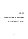
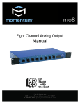
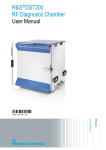
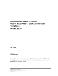
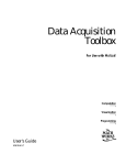
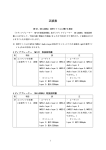
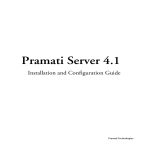
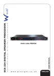
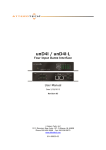
DMP900 Digital Media Platform User‟s Manual V1.07-W Digital Media Platform User Manual V1.07-W About This Manual This manual describes the installation, setup and operation of the DMP900 in details. Please read it carefully to make sure you can operate the multiplexer correctly. Important Avoid personal injury and product damage! Do not proceed beyond any symbol until you fully understand the indicated conditions. You may find this symbol in the document that accompanies this product. This symbol indicates important operating or maintenance instructions. Please use the cable of good quality and make sure the connector is in good condition. Please do not use the power supply that doesn‟t match the requirement. Please do not open the machine cover. Specifications and functions may be changed for improvement without notice in advance. Notices Trademark Acknowledgments All trademarks shown in this manual are trademarks of their respective owners. Publication Disclaimer Wellav Technologies Ltd. assumes no responsibility for errors or omissions that may appear in this publication. We reserve the right to change this publication at any time without notice. This document is not to be construed as conferring by implication, estoppels, or otherwise any license or right under any copyright or patent, whether or not the use of any information in this document employs an invention claimed in any existing or later issued patent. 2 / 116 Digital Media Platform User Manual V1.07-W Copyright Information in this publication is subject to change without notice. No part of this publication may be reproduced or transmitted in any form, by photocopy, microfilm, xerography, or any other means, or incorporated into any information retrieval system, electronic or mechanical, for any purpose, without the express permission of Wellav Technologies Ltd. Safety Instructions This warning symbol means danger. You are in a situation that could cause bodily injury. Before you work on any equipment, be aware of the hazards involved with electrical circuitry and be familiar with standard practices for preventing accidents. Electric Shock Hazard This equipment meets applicable safety standards. Refer to this equipment's Identification label or contact factory for details about regulatory compliance approvals. WARNING: To reduce risk of electric shock, perform only the instructions that are included in the operating instructions. Refer all servicing and installation to qualified service personnel only. Electric shock can cause personal injury or even death. Avoid direct contact with dangerous voltages at all times. The protective ground connection, where provided, is essential to safe operation and must be verified before connecting the power supply. Know the following safety warnings and guidelines: - Only trained and qualified personnel should be allowed to install, replace, or service this equipment. - Only qualified service personnel are allowed to remove chassis covers and access any of the components inside the chassis. - No user-serviceable parts inside. Do not open. Important Safety Instructions Read these instructions. Keep these instructions. Heed all warnings. Follow all instructions. Do not use this apparatus near water. Clean only with dry cloth. 3 / 116 Digital Media Platform User Manual V1.07-W Do not block any ventilation openings. Install in accordance with the manufacturer's instructions. Do not install near any heat sources such as radiators, heat registers, stoves, or other apparatus (including amplifiers) that produce heat. Protect the power cord from being walked on or pinched particularly at plugs, convenience receptacles, and the point where they exit from the apparatus. Only use attachments/accessories specified by the manufacturer. Use only with the cart, stand, tripod, bracket, or table specified by the manufacturer, or sold with the apparatus. When a cart is used, use caution when moving the cart/apparatus combination to avoid injury from tip-over. Unplug this apparatus during lightning storms or when unused for long periods of time. Refer all servicing to qualified service personnel. Servicing is required when the apparatus has been damaged in any way, such as power-supply cord or plug is damaged, liquid has been spilled or objects have fallen into the apparatus, the apparatus has been exposed to rain or moisture, does not operate normally, or has been dropped. WARNING: To reduce the risk of fire or electric shock, do not expose this apparatus to rain or moisture. The apparatus shall not be exposed to dripping or splashing and no objects filled with liquids, such as vases, shall be placed on the apparatus. Installation Site When selecting the installation site, comply with the following: Protective Ground - The protective ground lead of the building's electrical installation should comply with national and local requirements. Environmental Condition - The installation site should be dry, clean, and ventilated. Do not use this equipment where it could be at risk of contact with water. Installation Requirements Installation of the equipment must comply with local and national electrical codes. Equipment Placement Make sure the mounting surface or rack is stable and can support the size and weight of this equipment. The mounting surface or rack should be appropriately anchored according to manufacturer's specifications. Ensure this equipment is securely fastened to the mounting surface or rack where necessary to protect against damage due to any disturbance and subsequent fall. To prevent personal injury or damage to the chassis, never attempt to lift or tilt the chassis using the handles on modules (such as power supplies, fans, or cards); 4 / 116 Digital Media Platform User Manual V1.07-W these types of handles are not designed to support the weight of the unit. Installation of this equipment in a rack should be such that the amount of airflow required for safe operation of this equipment is not compromised. Only install this equipment in a humidity- and temperature-controlled environment that meets the requirements given in this equipment's technical specifications. AC Power This product requires short-circuit (overcurrent) protection to be provided as part of the building installation. Install only in accordance with national and local wiring regulations. The outlet must be near this equipment and must be easily accessible. Connect this equipment only to the power sources that are identified on the equipment-rating label normally located close to the power inlet connector(s). The plug-socket combination must be accessible at all times, because it serves as the main disconnecting device. Always pull on the plug or the connector to disconnect a cable. Never pull on the cable itself. Unplug this equipment when unused for long periods of time. Circuit Overload Know the effects of circuit overloading before connecting this equipment to the power supply. Take care when connecting units to the supply circuit so that wiring is not overloaded. WARNING: Consideration should be given to the connection of this equipment to the supply circuit and the effect that overloading of circuits might have on overcurrent protection and supply wiring. Appropriate consideration of information given on the equipment-rating label should be used when addressing this concern. General Servicing Precautions WARNING: Avoid electric shock! Opening or removing this equipment's cover may expose you to dangerous voltages. Be aware of the following general precautions and guidelines: Wristwatch and Jewelry - For personal safety and to avoid damage of this equipment during service and repair, do not wear electrically conducting objects such as a wristwatch or jewelry. Lightning - Do not work on the system or connect or disconnect cables during periods of lightning activity. Labels - Do not remove any warning labels. Replace damaged or illegible warning labels with new ones. 5 / 116 Digital Media Platform User Manual V1.07-W Covers - Do not open the cover of this equipment and attempt service unless instructed to do so in the instructions. Refer all servicing to qualified service personnel only. The covers are integral part of the safety design of the product. Do not operate the unit without the covers installed. Safety Checks - After service, assemble this equipment and perform safety checks to ensure it is safe to use before putting it back into operation. Electrostatic Discharge Electrostatic discharge (ESD) results from the static electricity buildup on the human body and other objects. This static discharge can degrade components and cause failures. Take the following precautions against electrostatic discharge: Use an anti-static bench mat and a wrist strap or ankle strap designed to safely ground ESD potentials through a resistive element. Keep components in their anti-static packaging until installed. Avoid touching electronic components when installing a module. 6 / 116 Digital Media Platform User Manual V1.07-W Contents CHAPTER1 DMP OVERVIEW .................................................................................................. 9 1.1 GENERAL ........................................................................................................................... 9 1.2 THE HOUSING .................................................................................................................... 9 1.3 FRONT PANEL & LED INDICATORS .................................................................................... 10 1.4 INTRODUCTION TO EACH I/O MODULE ............................................................................... 11 1.4.1 Modular Concept ..................................................................................................... 11 1.4.1.1 4-DVB-S/S2 module .............................................................................................12 1.4.1.2 4-DVB-C/T module ...............................................................................................13 1.4.1.3 Gigabit IP module .................................................................................................14 1.4.1.4 CI module .............................................................................................................15 1.4.1.5 4-ASI I/O module ..................................................................................................16 1.4.1.6 2-SD&HD H.264 SDI/AV Encoder module ...........................................................17 1.4.1.7 Gigabit Scrambler module ....................................................................................18 1.4.1.8 8-QAM/4-COFDM module ....................................................................................19 1.4.1.9 TC2 & TC4 Transcoder module............................................................................20 CHAPTER2 INSTALLATION .................................................................................................. 22 2.1. INTRODUCTION ................................................................................................................ 22 2.2. INSTALLATION PREPARATION ........................................................................................... 22 2.3 OPERATING TEMPERATURE .............................................................................................. 23 2.4 RACK MOUNTING.............................................................................................................. 23 2.4.1 Tools and Accessories .............................................................................................23 2.4.2 Mounting Requirements ..........................................................................................23 2.4.3 Mounting the DMP...................................................................................................24 2.5 CONNECTING THE AC POWER .......................................................................................... 24 2.6 CABLING THE MANAGEMENT PORTS.................................................................................. 25 CHAPTER3 OPERATION GUIDE........................................................................................... 26 3.1 OPERATION THROUGH NETWORK MANAGEMENT SOFTWARE ............................................. 26 3.1.1 Assigning IP Addresses ...........................................................................................26 3.1.2 Main Interface Introduction ......................................................................................29 3.1.3 Parameters Setting of the Mainboard .....................................................................37 3.1.4 Parameters Setting of the Sub-module ...................................................................49 3.1.5 Program Input and Output Operation ......................................................................74 7 / 116 Digital Media Platform User Manual V1.07-W 3.1.6 Receiving Signal Auto- Backup Function ..............................................................104 3.1.7 Configuration importation and exportation ............................................................108 3.2 OPERATION THROUGH FRONT PANEL .............................................................................. 110 3.2.1 Front Panel Control Buttons .................................................................................. 111 3.2.2 Front Panel Operation Menu Structure ................................................................. 112 3.2.3 Front Panel Operation Procedure ......................................................................... 113 CHAPTER4 EQUIPMENT SPECIFICATIONS...................................................................... 114 CHAPTER5 TERMINOLOGIES ............................................................................................ 115 8 / 116 Chapter1 DMP Overview 1.1 General DMP900 Digital Media Platform is the new generation of intelligent headend processing equipment. With a central processing capability of 384 TS streams (~1500 programs), this compact, high density 1RU equipment comes with 6 independent module slots. All six modules can be hot-swapped and hot-inserted to support the growing requirements of network operators. Each module can be configured individually base on the application including receiving, encoding, decoding, transmodulating, transcoding, ASI to IP mutual conversion, scrambling, descrambling, multiplexing, and QAM/OFDM modulation. Of total 6 I/O slot, each I/O slot can be equipped with: an ASI Interface module containing 4 ASI ports for input/output stream a GbE Interface module containing one pair of Gigabit Ethernet ports for input and output IP stream a DVB-S/S2 module provided with 4 RF input ports a DVB-C/T module provided with 2 RF input ports (receive 4 frequencies) and 2 RF loop out ports a DVB-CI module containing dual CI slots a 8-QAM/4-OFDM module provided with 1 RF output ports a 4-OFDM module provided with 1 RF output ports a GbE interface scrambling module for up to 1G data scrambling a MPEG-2/MPEG-4 transcoder module a SD/HD H.264 HDMI encoder module a CVBS/HDMI decoder module a SD/HD SDI decoder module 1.2 The Housing The DMP housing is a compact, modular 1 RU high 19-inch chassis containing six I/O slots and two PSU slots. The housing is rear loadable, meaning the cards, PSUs, and slot cover plates are loaded via the rear panel of the housing. 9 / 116 Digital Media Platform User Manual V1.07-W Two PSU Slots Hot-swappable I/O module 1.3 Front Panel & LED Indicators 1 2 3 4 1. LCD Display 2. Front panel operation Keys 10 / 116 5 6 7 8 Digital Media Platform User Manual V1.07-W 3. Power indicator Power On: green LED indicator is ON Power Off: LED indicator is OFF 4. Mainboard indicator Green: normal Red: Error detected 5. Module indicator Green and flashing: module is under initiation Green: normal Red and flashing: initiation fails Red: error detected 6. Menu & OK operation buttons 7. Reset button 8. Ethernet interface for remote management control 1.4 Introduction to Each I/O Module 1.4.1 Modular Concept The DMP fully incorporates the modular concept with built around a 1 RU high housing. The flexible modular concept ensures really easy system application switch and capacity upgrades. The following DMP module is available: 4-DVB-S/S2 module 4-DVB-C/T module Gigabit IP module CI module 4-ASI I/O module 2-SD&HD H.264 SDI/AV Encoder module Gigabit Scrambler module 8-QAM module 4-OFDM module 2-MPEG2 to MPEG4 Transcoder module More modules will be available at a later date. Please contact your service provider for the details. When the DMP leaves our assembly line, the device is configured as ordered. When the device is not fully populated, the device can always be upgraded at a later date by 11 / 116 Digital Media Platform User Manual V1.07-W adding or replacing different modules. 1.4.1.1 4-DVB-S/S2 module The DVB-S/S2 module is equipped with 4 BNC-type ASI interfaces ports. Each ASI interface can be connected to one single LNB cable of a dish and receive whole programs transmitted on a satellite transponder. Up to 5 DVB-S/S2 modules can be installed on a DMP unit, which means that one DMP can support up to 20 DVB-S/S2 input signals (20 transponders). Description Inputs Frequency Range Symbol Rate FEC Mode Input Level LNB Power Supply 22KHz Specification 4XRF inputs, 75Ω , F-type connector 950~2150MHz QPSK: 2~45MBauds 8PSK: 2~37Mbauds QPSK: 1/2, 2/3, 3/4, 5/6, 7/8 8PSK: 2/3, 3/4, 4/5, 5/6, 8/9, 9/10 -65dBm~-25dBm Vertical: 11.5V~14.0V Horizontal: 16.0V~19.0V 18~26KHz 12 / 116 Digital Media Platform User Manual V1.07-W 1.4.1.2 4-DVB-C/T module Similar to DVB-S/S2 module, this module is for receiving DVB-C/T signals, and each module can support up to 4 DVB-C/T signal receiving and loop out. One DMP supports to install a max of 5 DVB-C/T modules. Description Inputs Frequency Range Symbol Rate FEC Mode Input Level QAM Mode Specification 2XRF inputs, 75Ω , F-type connector 2Xloop out DVB-C module: 48~862MHz DVB-T module: 50~858MHz DVB-C module: 1.0~6.9MBauds DVB-T module: 0.45~7.0MBauds DVB-C module: Annex A/C, Annex B (optional) DVB-T module: 2K & 8K (FTT) DVB-C module: 32~105dBuV DVB-T module: -96~-6dBm 16/32/64/128/256 QAM 13 / 116 Digital Media Platform User Manual V1.07-W 1.4.1.3 Gigabit IP module A GbE Interface Card of the DMP is provided with 2 Gigabit Ethernet interfaces, giving the card a total throughput of 1 Gbps in and 1 Gbps out. To protect video services transported over IP networks from impairments caused by network jitter, IP packet loss, or out-of-order IP packets, a GbE Interface Card with FEC option based on Pro-MPEG COP3 is provided. The following illustration depicts a standard GbE Interface Card and a GbE Interface Card with FEC option. Description Input/Output Gigabit-8 IP Max Input/Output Gigabit-32 IP Max Input/Output Error Correction Encapsulation Protocol Broadcasting Type Specification 2X1000Base-T, RJ45 (one for input/output; one for backup output) 8 input TS streams and 8 output TS streams 32 input TS streams and 32 output TS streams Pro-MPEG FEC MPEG-2/MPEG-4 TS over UDP/RTP Unicast & Multicast 14 / 116 Digital Media Platform User Manual V1.07-W 1.4.1.4 CI module The CI module is with 2 independent common interface slots, which supports multi-channel descrambling by inserting different CAM modules. Description Interface Standard CA methods CAS support Specification 2Xcommon Interface slots DVB/NRSS-B/DAVIC V1.2 Multicrypt, Simulcrypt Conax, Irdeto, Viacess, CTI, Nagravision, DVCrypt, etc. 15 / 116 Digital Media Platform User Manual V1.07-W 1.4.1.5 4-ASI I/O module The ASI Interface module of the DMP is provided with 4 BNC-type ASI interface ports, which can individually be configured as either ASI input port or ASI output port using the management software of the device. All ASI interface ports support Multiple Program Transport Streams (MPTS) as well as Single Program Transport Streams (SPTS) according to ISO/IEC 13818. Each DMP can be equipped with maximum six ASI Interface Modules, meaning that the device can support a max of 24 ASI interfaces. 16 / 116 Digital Media Platform User Manual V1.07-W 1.4.1.6 2-SD&HD H.264 SDI/AV Encoder module The SD&HD H.264 encoder module supports two A/V and SD/HD SDI input streams encoding simultaneously. Due to the highly encoding efficiency of the H.264 technology, this encoder module enables the operator to encode the analog and SDI streams at very low bitrate for transmission. Description Inputs Video Processing Video Format Image Format Definition Aspect ratio GOP configurable Video bit rate Audio Processing Audio Format Sampling frequency Audio mode Specification 2×SDI, BNC 75Ω / 2×CVBS, 2×Audio inputs (balanced and unbalanced) MPEG-4 / H.264-AVC HP@L4 PAL and NTSC 1920x1080x59.94i/50; 1440x1080x 59.94i/50i; 1280x720x59.94p/50p; 720x480x59.94i; 720x576x50i 4:3, 16:9 I, IP, IPB, IPBB CBR & VBR, SD 1.0~20Mbps; HD 6.0~20Mbps MPEG-1 and MPEG-2 Layer-I, II, AAC, Dolby AC-3 (optional) 48KHz Stereo, joint stereo, dual channel, mono 17 / 116 Digital Media Platform User Manual V1.07-W 1.4.1.7 Gigabit Scrambler module A GbE Interface Card of the DMP is provided with 1 Gigabit Ethernet interface which is used to communicate with CAS server. The card is capable of a total throughput of 1 Gbps in and 1 Gbps out. The module is fully compliant with DVB Simulcrypt standard and supports up to 4 different CAS Simulcrypt application. 18 / 116 Digital Media Platform User Manual V1.07-W 1.4.1.8 8-QAM/4-COFDM module This modulation module supports either 8 channels QAM or 4 channels COFDM modulation output. With up to 5 modules on a single DMP unit, the DMP supports up to 40RF QAM or 20RF COFDM outputs. 19 / 116 Digital Media Platform User Manual V1.07-W 1.4.1.9 TC2 & TC4 Transcoder module The TC2 & TC4 transcoder module is capable of transforming MPEG-4/H.264 programs to MPEG-2 encoding format (TC2) or reversely MPEG-2 to MPEG-4/H.264 transforming (TC4). On a single module, it is optionally to support up to 4 programs transcoding which enables as up to 20 programs transcoding processing on a DMP unit simultaneously. MPEG-4 to MEPG-2 Transcoder Module (TC2) Description Specification Video Processing Video Output Format Video Standard Video Resolution Aspect ratio 2 channels (default) 4 channels (optional) MPEG-2 4:2:0 MP@ML PAL and NTSC 480i, 576i 4:3, 16:9 Video encoding bit rate CBR & VBR, 1.0~20.0Mbps Processing Channel Quantity Audio Processing 20 / 116 Digital Media Platform User Manual V1.07-W Audio Format MPEG-1 Layer- I Sampling frequency 64~384KHz Audio mode Stereo, joint stereo, dual channel, single channel MPEG-2 to MEPG-4 Transcoder Module (TC4) Description Specification Video Processing Aspect ratio 2 channels (default) 4 channels (optional) MPEG-4 / H.264-AVC HP@L4 1920x1080 (60p/59.94p/30p/24p/60i/59.94i/50i); 1280x720 (60p/59.94p/50p); 720x480 (60i); 720x576 (50i) 4:3, 16:9 Video bit rate CBR & VBR, 1.0~20Mbps Processing Channel Quantity Video Output Format Definition Audio Processing Audio Format MPEG-1/-2 Layer-I, II Sampling frequency 64KHz~384KHz 21 / 116 Digital Media Platform User Manual V1.07-W Chapter2 Installation 2.1. Introduction This chapter contains the information for technicians installing the DMP900. WARNING: Allow only authorized and qualified service personnel to install, operate, maintain, and service this product. Otherwise, personal injury or equipment damage may occur. 2.2. Installation Preparation Before You Start Make sure that the chassis is in good condition and that you have the tools and equipment needed. Unpacking and Inspecting the Housing As you unpack the housing, inspect it for shipping damage. If you find any damage, contact the customer services department. Chassis Dimensions The following drawing shows the dimensions of the DMP. 490mm 44mm 440mm 22 / 116 Digital Media Platform User Manual V1.07-W 2.3 Operating Temperature The DMP is designed to operate within a specified operating temperature range. Please install the DMP in an environment that fits for the operation requirements. WARNING: Avoid damage to the DMP. Your warranty is void if you operate this product above the maximum specified operating temperature. We recommend the following activities to moderate the operating temperature: Mount ventilation profiles at the bottom and top of the 19-inch equipment rack. This allows the fresh air to enter and the hot air to leave the rack. Place the 19-inch equipment rack in a conditioned room with a temperature below 25°C (77°F). 2.4 Rack Mounting 2.4.1 Tools and Accessories You need the following tools and accessories for mounting the unit: Screwdriver. Support brackets and rack mounting screws. 2.4.2 Mounting Requirements Follow the mounting guidelines below: Use 19-inch racks with the appropriate depth. Mount the unit adequately to secure optimal operation and reliability. Use rack-compatible support brackets to support the unit properly. Note: There are 2 brackets shipped along with the DMP for installing to the rack. The brackets must be installed on the rack for holding the DMP properly. Install brackets to the rack with screws. Install brackets to the rack with screws. 23 / 116 Digital Media Platform User Manual V1.07-W Pay attention to the mechanical loading and stability to avoid hazardous situations. 2.4.3 Mounting the DMP It is of great importance to place the DMP and its components in a conditioned room within the ambient temperature specifications. Perform the following procedure to install the DMP. 1. Unpack the device. 2. Select a 1 RU high location in the rack. 3. If the rack holes are not threaded, install a cage nut in the top and bottom holes of the selected 1 RU space. 4. Mount a left and right support bracket in the 19-inch rack. 5. Slide the housing completely in the 19-inch rack with the bottom being supported by the support brackets. 6. Insert the front panel rack mounting screws through the washers into the threaded holes or cage nuts. 7. Tighten the front panel rack mounting screws. 2.5 Connecting the AC Power Perform the following steps to connect AC power to the DMP. 1. Connect the AC power cord to the back of the device. 2. Connect the power cord to the AC power outlet. Note: If your DMP is equipped with two AC type power supply units, it is advisable to plug each power supply unit into a separate dedicated branch circuit. Once the DMP is powered up, the device starts booting. Booting the DMP can take some time depending on the configuration and the features of the device. Caution: Do not insert nor unplug a powered power supply from the chassis without disconnecting the power source. When a DMP is brought from a cold into a warm environment, the device should be acclimated to the environment temperature and humidity conditions for at least 30 minutes. Non-acclimated devices may not meet the technical specifications as described. Powering up a non-acclimated device may result in damage to the component and/or chassis. 24 / 116 Digital Media Platform User Manual V1.07-W 2.6 Cabling the Management Ports Introduction The operation on the DMP will be mostly carried out through the Wellav Network Management Software (NMS). Please connect the DMP management port with the monitoring computer in advance Required Cable Use Category 5 (CAT5E, minimum) STP Ethernet cable for connecting the management ports. Switch 25 / 116 Digital Media Platform User Manual V1.07-W Chapter3 Operation Guide 3.1 Operation through Network Management Software 3.1.1 Assigning IP Addresses The DMP is equipped with a 10/100Base-T port for communication with a remote control and monitoring PC. When the DMP leaves our factory, both Ethernet ports are configured with the following parameter settings: Parameter IP address Subnet Mask address Gateway Default Setting 192.168.1.16 255.255.255.000 192.168.1.1 Before the DMP can be connected to a LAN, the default IP settings of the DMP must be changed to correct values according to the actual network environment. Note: Ethernet interfaces with conflicting IP address may cause serious network problems. Contact your network administrator for correct IP settings. Both Ethernet interfaces should be connected to a different subnet. Connect your remote PC and DMP to the same network without any L3 routers in-between. 26 / 116 Digital Media Platform User Manual V1.07-W To Adapt the IP Settings Perform the following procedure to assign IP addresses to the DMP. 1. Use a PC with IP settings of 192.168.1. X and connect the PC to a hub or a router. 2. Connect the 10/100Base-T interface of the DMP to the LAN connection point. Use straight-through cable for connection to a hub/router to set up connection with the monitoring PC. Note: The DMP can be connected directly to a local PC using a crossover Ethernet cable. 3. Start the Network Management Software on the accessory CD. Network Management Software Icon 4. For first time log on, User Name and Password are required. Default User Name and Password are “admin”. Select “Remember Me” if you want to log on without inputting the User Name/Password next time. Click “Login” to get in the NMS main interface. 5. In the main interface, select “System” tab. 27 / 116 Digital Media Platform User Manual V1.07-W 6. In the “System” tab, it lists the DMP basic system information of the main board and hardware/software information of each inserted sub-module. To modify the default IP address, type in the new IP address in the “IP Address” column, then click “Set” button. The DMP will reboot automatically and apply with the new IP address. 28 / 116 Digital Media Platform User Manual V1.07-W 3.1.2 Main Interface Introduction The following screen will display after program startup: ① ② ③ ④ The interface can be divided into four areas according to its functionality. ① Toolbar. It includes shortcut to change password and save setting etc. ② Equipment list. If more than one DMP is connected to the NMS, the DMP will be listed in this area by its IP address. ③ Parameter setting and configuration area. The parameters of the DMP are shown and configured here by selecting different tabs. This is the main operation area of the NMS. ④ Event information window. 3.1.2.1 Toolbar 29 / 116 Digital Media Platform User Manual V1.07-W (1) Password: select to change the login password. (2) AutoLogin: to choose whether auto log on the NMS (without inputting password) next time. (3) Exit: exit the NMS. (4) Help: shows the version of the management software and HELP information. (5) add new device to the NMS. After selecting this button, a “Add device” window shows up 30 / 116 Digital Media Platform User Manual V1.07-W Device Type: Choose “DMP” in the list. Device Name: Uneditable IP Address: type the target add device IP address Port: must be “30” Press “OK” and a new device will be added to the device list. (6) to delete a selected device from the list. (7) to change the login password. Equals to the “Password” button. (8) to display the “HELP” information and NMS software version. Equals to the “HELP” button. (9) to scan other DMP device which is connected to the same network. 31 / 116 Digital Media Platform User Manual V1.07-W 3.1.2.2 Equipment List In this section, it shows the connection status of all the DMPs that the NMS scans in the network, and user can do “Connecting the Device”, “Add Device”, “Delete Device” operation. (1) If this icon is in Green, it means the connection of the DMP and PC has been successfully set up. (2) If this icon is in Red, it means the DMP is not connected. Please check the network connection and the IP setting of the DMP. (3) Connecting the device: follow the below steps to connect the device shown on the equipment list: Select a device IP address on the equipment list area using the left mouse button; Double click the left mouse button on the selected device. The NMS starts to connect the device and requesting parameters data from the device. 32 / 116 Digital Media Platform User Manual V1.07-W Connection set-up completes. (4) Add device: In case the DMP is not automatically detected by the NMS, user can manually add the device to the NMS. Follow the below procedures to add a device: Move the cursor to the ② Equipment List area. Use the mouse right button to click on the blank area. A “Add Device” menu shows up. 33 / 116 Digital Media Platform User Manual V1.07-W Select “Add Device” to enter the device configuration window. Device Type: Choose “DMP” in the list. Device Name: Not editable IP Address: type the target add device IP address Port: must be “30” Press “OK” and a new device will be added to the device list. (5) Edit device: to edit the existing device connection parameters. Operation: Select a device, click the mouse right button. In the pop-up menu, select “Edit Device”. 34 / 116 Digital Media Platform User Manual V1.07-W (6) Delete device: to delete the selected device from the NMS list. Operation: Select a device, click the mouse right button. In the pop-up menu, select “Delete Device”. 3.1.2.3 Parameter setting and configuration area This is the main operation and configuration interface of the NMS. All the parameters setting and control on the DMP and each module is conducted here. Please refer to Chapter 3.1.3 for the detailed operation instruction. 35 / 116 Digital Media Platform User Manual V1.07-W 3.1.2.4 Event information window This area shows the system event information including: current connected device name, device type, IP address, connection port, online/off-line status, and event time. 36 / 116 Digital Media Platform User Manual V1.07-W 3.1.3 Parameters Setting of the Mainboard The Parameters Setting and System Application area includes the operation on the DMP mainboard and sub-module. Setting and Configuration on the Mainboard The mainboard configuration includes 4 tabs: “Status”, “Program Info”, “System”, “License” and “Upgrade”. Status: by selecting this item the NMS displays the current system operation data status of the DMP. User can switch between tab under the “Status” to check the current working status of mainboard and inserted modules. 1. Different colors of histogram indicate different meaning: Orange: the total input bit rate; Blue: the effective input bit rate; 37 / 116 Digital Media Platform User Manual V1.07-W Yellow: the total output bit rate; Green: the effective output bit rate; Red: alarm indicator, it means the actual output bit rate (it‟s proportional to the amount of the programs you transfer from input port to output port in „Program Info‟) is more than the output bit rate of some channel you set in sub-board 2. Communicate Status indicates the communication status between NMS and DMP900 equipment. Green: the communication is normal. All the parameters in NMS are updated according to DMP900 synchronously. Red: the communication is abnormal. The parameters in NMS maybe not updated in time. You need check the network connection and restart the NMS. Program Info: this menu is to configure the input and output program of the DMP. 38 / 116 Digital Media Platform User Manual V1.07-W ① Input Program Configuration ② Output Program Configuration ③ Operation Buttons ① Input Program Configuration: the “Input Program Configuration” is on the left side of the “Program Info” window. It displays all the inserted modules information and the received input streams. 4XDVB-S2 Module inserted in Slot 1 Port 1 & 2 of DVB-S2 module are in used. 39 / 116 Digital Media Platform User Manual V1.07-W Board1~6 represents the corresponding slots of the DMP. If the slot is inserted with a card module, the corresponding Board No. will be displayed on the “Input Program Configuration” window, and the name of the inserted module will be displayed after the Board No. For empty slot, no Board No. will be displayed. Port No.: represents each physical port of the inserted module. Scan the input TS: after the parameters of the inserted module are properly configured (refer to Chapter 3.1.4 of this manual), select one port which is connected with input stream, and then click the mouse right button and select “Scan TS” menu. All the input stream of that port will be scanned and displayed. Scan the port that is fed with input stream Scan completes and receives data 40 / 116 Digital Media Platform User Manual V1.07-W ② Output Program Configuration: In the “Output Program Configuration” window, it shows the inserted module which can be set to transmit output stream. These kinds of modules include the Gigabit IP module, ASI module, 8-QAM and 4-OFDM module, etc. Settings on the Output Program please refer to Chapter 3.1.5 of this manual. ③ Operation Buttons: the operation buttons include 4 different function buttons: Transfer button: to transfer the selected stream/PID from the input program window to the output program window. Set button: to apply the changes to the NMS. The setting will lose if the NMS is close or DMP is powered off. 41 / 116 Digital Media Platform User Manual V1.07-W To obtain/refresh the current parameters status of the DMP mainboard. To save the configuration. The saved data can be kept after NMS is closed or DMP power off. Import a configuration file. Export the current settings of the DMP and save as a configuration file. To eliminate all the settings in the input and output window. System: the “System” setting provides the system information of the DMP mainboard and inserted modules, including the mainboard IP address, Subnet Mask, Gateway, Trap IP address, MAC address and hardware/software version of each module. 42 / 116 Digital Media Platform User Manual V1.07-W License: Wellav DMP provides very flexible license management on its modules. User can purchase new license to expand the module capability along with the business development, e.g. to update the license of a QAM module to let it support more channel output. License update procedure: Select “License” tab in the NMS. In the “License” main interface, select a module which you want to update the license. Click “ExportLicense” button to save the license file of the selected module, e.g. to export the old license as “license backup.license” 43 / 116 Digital Media Platform User Manual V1.07-W Send the license file “license backup.license” to Wellav for an updated license. Select “UpgradeLicense” button to import the new license file from Wellav. 44 / 116 Digital Media Platform User Manual V1.07-W 45 / 116 Digital Media Platform User Manual V1.07-W License update succeeds. Upgrade: In the “Upgrade” tab, user can upgrade the software version of the DMP mainboard and its module components. The upgrade usually is either to fix any bug or implement new features. Improper upgrade operation might damage the DMP. Contact your service provider before the upgrade. Make sure the network connection and power supply is in good condition before the upgrade. NEVER TURN OFF THE DMP, CUT OFF THE POWER SUPPLY OR UNPLUG ANY MODULAR CARD DURING THE UPGRADE. Standard upgrade procedures: Select “Upgrade” tab and open the “Upgrade” interface; 46 / 116 Digital Media Platform User Manual V1.07-W Click “Select File” button to open the upgrade files; After selecting the upgrade file, the upgrade file will be listed in the “Optional” window. Click the button to transfer the upgrade file from the left “Optional” window to the right “Selected” window. 47 / 116 Digital Media Platform User Manual V1.07-W Note: 1. For some sub-modules upgrade, the upgrade files will be automatically put into the “Selected” window after selecting the file. 2. To unselect the upgrade file, double click the left mouse button on the selected file to remove it from the selected list. Click the “Start” button to start the upgrade. The upgrade process can be monitored in the “Send Progress” bar, “Write Flash Progress” bars and the Info window. A notifying window shows up after successful upgrade. 48 / 116 Digital Media Platform User Manual V1.07-W 3.1.4 Parameters Setting of the Sub-module In accordance with the 6 modular slots of the DMP, there are total 6 module parameters setting tabs in the configuration menu. Each tab represents the corresponding slot of the DMP. Each tab displays the name of the inserted module. If the slot is empty, then the tab shows “Empty” as well. It is of great importance to correctly set the parameters of each module so that the DMP can work properly. Please go through this section for the module setting details before operating the DMP. DVB-C Receiving Module The DVB-C module supports receiving programs compliant with DVB-C standard from 4 different frequencies simultaneously. 4-DVB-C Receiving Module The config page of this module includes two parts: Status: indicates the basic parameter and locking status of input signal. 49 / 116 Digital Media Platform User Manual V1.07-W Setting: set the parameters for receiving the input signal. After setting all parameters, you should press the „Set‟ button to save the settings. Status The parameters of this part are derived from the input signal; they will be gotten automatically when the input signal is available, and cannot be changed by the user. Introduction to the parameters of “Status” Parameters Description Port Indicates which input port the channel comes from. Status Indicates whether the input signal is LOCK) or UNLOCK. Size Indicates the packet size within the input TS stream. (188 or 204) Indicates the total bit rate of input signal, including the valid and null Total Rate packet. The unit is Mbps Indicates the bit rate of valid packet (excluding the null packet). The Effective Rate unit is Mbps. Signal Strength Indicates the strength of input signal Signal Quality Indicates the quality of input signal Setting In order to receive the input signal successfully, it‟s important to set the correct parameters 50 / 116 Digital Media Platform User Manual V1.07-W in the setting menu. The key parameters Mode‟. Parameters Port Frequency Symbol Rate QAM Mode of a received channel include „Frequency‟, „Symbol Rate‟, and „QAM Description Indicates which input port the channel comes from. Frequency on which the channel is transmitted. The unit is in KHz. Symbol rate of the input channel. The unit is in KS/s. Select the actual QAM mode of the input channel. Note: the input signals of Port 1&2 are from the „RF-IN 1/2‟ port of tuner 1, and the input signals of Port 3&4 are from the „RF-IN 3/4‟ port of tuner 2. Please contact your program provider for the parameters details of the channel if you are not clear about. DVB-S/S2 Receiving Module The DVB-S/S2 module supports receiving programs compliant with DVB-S or DVB-S2 standard from 4 different frequencies (transponders) simultaneously. The config page of this module includes two parts: Status: indicates the basic parameter and locking status of input signal. Setting: set the parameters for receiving the input signal. After setting all parameters, you should press „Set‟ button to save the settings. 51 / 116 Digital Media Platform User Manual V1.07-W Status The parameters of this part are derived from the input signal; they will be gotten automatically when the input signal is available, and cannot be changed by user. Introduction to the parameters of “Status” Parameters Description Port Indicates which input port the channel comes from. Status Indicates whether the input signal is LOCK) or UNLOCK. Size Indicates the packet size within the input TS stream. (188 or 204) Indicates the total bit rate of input signal, including the valid and null Total Rate packet. The unit is Mbps Indicates the bit rate of valid packet (excluding the null packet). The Effective Rate unit is Mbps. Mode Indicates which standard the input signal is, DVB-S or DVB-S2. FEC CodeRate Indicates the code rate which is used in FEC. C/N Indicates the real-time carrier to noise ratio. BER Indicates the real-time bit error rate. 52 / 116 Digital Media Platform User Manual Constellation Center Frequency V1.07-W Indicates the constellation used in the input signal. Indicates the center frequency from the transponder. The unit is MHz. Setting In order to receive the input signal successfully, it‟s important to set the correct parameters in the setting menu. Parameters of the „Setting‟ menu: Parameters Description Port Indicates which input port the channel comes from. Input the frequency of transponder which you want to receive SatFrequency programs from. The unit is MHz. SymbolRate Input the symbol rate of the transponder. The unit is KS/s. Select the voltage provided to LNB (13V for vertical or 18V for Polarization Horizontal). Select the band of LNB you want to use, including Auto, Forced Low BandSelection and Forced High. Type Select the actual type of your LNB, Single Band or Dual Band. LOLowfrequency The low frequency of LNB. The unit is MHz. LOHighFrequency The high frequency of LNB. The unit is MHz. Bias Enable or disenable the polarization setting. Note: 1. Parameters of „FECCodeRate‟ can be automatically recognized by the NMS; 2. Only LNB 1 & 3 inputs support polarization setting. LNB 2 & 4 cannot provide power (13V or 18V) to the LNB. DVB-ASI I/O Module The ASI module is equipped with four BNC-type ASI connectors, supporting four ASI input/output. The default setting of the module is: Ports 1 & 2 is for input, and Ports 3 & 4 is for output. User can specify the port to be input or output at any time through the NMS. 53 / 116 Digital Media Platform User Manual V1.07-W Settings in the ASI module NMS The key parameters in this NMS interface include: Parameters Description Type Set each ASI port to be Input or Output. PacketSize Set 188 or 204 packet size for outputs. Mode Set ASI port into CBR or VBR for output. ConstantRate(Mbit) Set constant bitrate for ASI output. MaxRate(Mbit) Set max bitrate for ASI output. MinRate(Mbit) Set min bitrate for ASI output. Note: For the input parameters, it is automatically obtained by the NMS when connected with the input signal. It is in not editable status. 54 / 116 Digital Media Platform User Manual V1.07-W Gigabit IP I/O Module The IP module is equipped with two RJ45 connectors. One is for the IP stream input/output; the other is for stream output only, it‟s as the backup output when you set „TS/IP‟ port as output mode. The configuration of the IP module can be done through its NMS. IP Module Setting Interface By selecting the „IP‟ tab on the DMP NMS operation interface, the IP module setting interface will be displayed. The settings on the IP module include the settings on the „Receiver‟, „Transmitter‟ and „System‟. „System‟ Setting of the IP I/O Module 55 / 116 Digital Media Platform User Manual V1.07-W In the „System‟ setting menu, user need to set correct parameters for the IP module such as the IP address, subnet Mask, Gateway, etc, so that the module can work normally in the network. Parameters IP Address Subnet Mask Gateway MAC Address SpeedMode IGMP Version Description Set IP address of IP module. The IP address of IP module is used for communication with basic unit of DMP that should be in the same IP section with IP address of DMP. Set Subnet Mark of the IP module Set Gateway of the IP module MAC address of the IP module Set RJ45 connection speed mode. The speed mode support 100Mbit and 1000Mbit. Set IGMP Version for multicast. The IGMP version setting should match the IGMP version of the switch in the network. „Receiver‟ Setting The „Receiver‟ setting menu is to set the IP input function for receiving multicast/unicast IP stream. 56 / 116 Digital Media Platform User Manual Parameters ChannelSelect Enable V1.07-W Description In this „ChannelSelect‟, user can select a channel to configure its parameters. On: enable the IP receiving function. Off: disable the IP receiving function. Note: this parameter setting applies to all channels. Channel configuration EnableChannel SourceIPAddress SourcePort Protocol ColPortMatching RowPortMatching FEC Parameter Enable or disable corresponding input channel Set the IP address of the multicast/unicast that are going to receive Set port of multicast/unicast Select UDP/RTP for multicast/unicast If the output IP stream quality looks not as good as the input stream, user can select to „Enable‟ these two options then to enable the FEC function. The bigger values it is, the stronger capabilities it has to correct the data mistakes. But the FECL and FECD should be less than 100. After setting all the parameters, you should press „Set‟ button to save the settings. „Transmitter‟ Setting The „Transmitter‟ setting menu is to set the IP output function for transmitting multicast/unicast IP stream to other devices. 57 / 116 Digital Media Platform User Manual Parameters ChannelSelect Enable V1.07-W Description In this „ChannelSelect‟, user can select a channel to configure its transmitting parameters. On: enable the IP receiving function. Off: disable the IP receiving function. Note: this parameter setting applies to all channels. Channel configuration EnableChannel SourcePort DestIPAddress Protocol EncapNumTSPackets TSPacketSize TypeofService Time To Live EnableVLAN VLAN ID FEC Parameter EnableFEC ColFECOnly InterleaveMode FECL FECD Enable or disable corresponding output channel Set port of multicast/unicast Set IP address of the multicast/unicast. Select UDP/RTP for multicast/unicast Rang 1~7. (Num 7 is recommended) Select 188/204 TS packet size Select one service type as your requirement. Type including: Normal, Min delay, Monetary cost, Max reliability, Max Throughput. Range is 1-255. (Num 8 is recommended) Enable/Disable VLAN. Set VLAN ID. Enable/Disable FEC Yes for only Col FEC, no for Col&Row FEC Mode includes: Annex_a, Annex_b and Off The bigger values it is, the stronger capabilities it has to correct the data mistakes. But the FECL and FECD should be less than 100. Bitrate Parameter Mode ConstantRate(Mbit) MaxRate(Mbit) MainRate(Mbit) Mode includes: CBR/VBR Set constant bitrate for output Set max bitrate for output Set min bitrate for output 8-QAM/4-COFDM Module The 8-QAM/4-COFDM module can output up to 8 separate RF QAM frequencies signals with its physical output interface. With adopting corresponding license key, the module can turn to a 4-COFDM module without changing the hardware. 58 / 116 Digital Media Platform User Manual V1.07-W 8-QAM/4-COFDM module NMS configuration interface: Parameters Bandwidth RF Level Description Select the bandwidth of output RF, 6M/7M/8M are available. Set RF output signal level in dBu, the value RF Level is 90dBu~115dBu SymbolRate (Channel Set symbol rate for the first four transmission frequencies 1~4) SymbolRate (Channel Set symbol rate for the last four transmission frequencies 5~8) Enable Switch „Enable‟ or „Disable‟ for the selected channel output Set the carrier frequency for the first modulation frequency. Note: for the RF frequencies of port 2~8, they will be set RF Frequency (KHz) automatically by the NMS base on the frequency of port 1 and the „Bandwidth‟ setting. Set modulation type of each modulators port. The modulation Mode mode can be QAM16, QAM32, QAM64, QAM128, QAM256. The maxrate is automatically calculated by the NMS according to MaxRate the QAM mode the user selects. The actualrate set by the user shall not exceed the maxrate to ensure best signal quality. The bitrate user set for the output. It is set by the user in other ActualRate related sub-module such as the encoding module. 59 / 116 Digital Media Platform User Manual V1.07-W CI Descrambling Module The CI descrambling module is for descrambling the input scrambled stream via CAM module. The module supports 2 CAMs working simultaneously. In the CI module NMS interface, there are four items for user to select/configure. Only after the parameters are correctly set can the CI module work normally. Parameters CAM No. Enable/Disable switch TSClock Description Indicates which CAM the user is operating. Enable--turn on the CI module and enable the input stream to pass through the CI module and get descrambled. Disable--Disable any input stream to pass through the CI module and thus the CI module will not be functional. !Please select Disable if no CAM is inserted in the CI module. The TSClock is selected according to the CAM and actual bitrate of input TS. Five options in the TSClock can be selected: 9MHz--support up to 72Mbit input TS. 9.5MHz--support up to 76Mbit input TS. 10.5MHz--support up to 84Mbit input TS. 11.5MHz--support up to 92Mbit input TS. 13MHz--support up to 104Mbit input TS. ! Please select default 9MHz for the TSClock if input TS is less than 72Mbit in total bitrate. And usually a standard CAM can support Max. 72Mbit data processing unless it has 60 / 116 Digital Media Platform User Manual Mode ConstantRate (Mbit) V1.07-W instruction for higher bitrate support. Selecting a wrong CAM output bitrate will cause video mosaic issue because the actual processed data exceeds the CAM Max. handling capability. CBR--the output descrambling TS bitrate is set at a bitrate which set in the ConstantRate. VBR--the output descrambling TS bitrate is changeable depending on the input TS. To set a fixed output bitrate for the CI module. It will take effect when user selects the CBR mode. !Please set a bigger bitrate value than the input TS rate and reserve a bit buffer. Note: for the descrambling operation on a program, please refer to “Descramble Operation”, page-51 of this manual for the details. 2-SD&HD H.264 SDI/AV Encoder Module The 2-SD&HD H.264 SDI/AV Encoder Module supports encoding 2 SDI channels or 2 AV channels simultaneously. Settings in the Encoder module NMS 61 / 116 Digital Media Platform User Manual V1.07-W Introduction to the parameters in this NMS: Parameters Channel Video Source Audio Source Video Max Encode Rate Video Min Encode Rate Video Encode Rate Audio Encode Rate Encode Rate GOP Struct Encode Mode Video PID Audio PID PCR PID PMT PID Program Number Transport Stream ID Provider Name Program Name Frame Rate Description Indicates which input port the channel comes from. To select the correct video source for the input. To select the correct audio source for the input. To set the Max. encode rate for VBR mode. To set the Min. encode rate for VBR mode. To set the encode rate for CBR mode. To choose the encoding bitrate for the audio. The total encode rate of video and audio contents. Calculated automatically by the software. To select GOP structure. Select CBR or VBR for the encoding mode. To edit the video PID. To edit the audio PID. To edit the PCR PID. To edit the PMT PID. To edit the program number. To edit the transport stream ID. To edit the program provider name. To edit the program name. To select correct frame rate according to the input source. 62 / 116 Digital Media Platform User Manual V1.07-W 1GB Scrambling Module Insert the scrambler module to a DMP empty slot, and select the “Scrambler” tab on the NMS to enter the scrambler configuration window: CAChannel: the scrambler module supports up to 4 CAS Simulcrypt. User can configure different settings for each CAS system by select different “CAChannel” in this item. 63 / 116 Digital Media Platform User Manual V1.07-W To ensure the scrambler module can set up connection successfully with the CAS server, user shall configure the correct parameters on the scrambler module IP Setting button: Click this button to set a IP address for the scrambler module per the network environment. 64 / 116 Digital Media Platform User Manual V1.07-W Other key parameters settings on the scrambler module: Each CAS system has a unique SystemID when it is registered in DVB. Please contact your CAS service provider if you don‟t know what the ID is. ECMGIPAddress Input the CAS server IP address. ECMGIPPort EMMGTCPPort EMMGUDPPort Shall input the same port no and ID setting as those on the CAS EMMPID server. Otherwise connection cannot be set up between the CAS EMMChannelID server and the scrambler module. EMMStreamID EMMDataID SystemID After inputting the correct parameters, the scrambler module shall connect successfully with the CAS server. Next is to add the AC Data for each program of a TS stream. Click “Add” button on the NMS 65 / 116 Digital Media Platform User Manual V1.07-W In the “Add ECM” window, input the ACData (Hex), and click “Add” to insert the AC Data. 66 / 116 Digital Media Platform User Manual V1.07-W After finishing all the parameters setting and the AC Data insertion, click “Set” button on the NMS to apply for the settings. After configuring on the scrambler module setting window, user shall operate in the “Program Info” tab to specify which program to be scrambled and transfer to the transmission module (QAM/IP/ASI) for output. Operation steps are as following: Select the program which is to be scrambled and transfer it from the signal source to the scrambler module at “Output Program Info”. (To know how to transfer programs, please refer to chapter 3.1.5) In below example picture, program “FujianTV1” is selected and is transferred from DVB-S2 module in “Input Program Info” window to scrambler module in “Output Program Info” window. 67 / 116 Digital Media Platform User Manual V1.07-W Edit the Network ID, TsID for the selected program, same as the setting in the CAS server for that program. Select the program name and click mouse right button to select “Scramble Setting”. 68 / 116 Digital Media Platform User Manual V1.07-W In the “Scrambler Setting” window, select an AC Data we previously input and click “OK” to bond with the selected program. 69 / 116 Digital Media Platform User Manual V1.07-W After the program is scrambled, the button indicators of the program name will turn to black color. The scrambling program stream will be automatically transferred to the Scrambler module in the “Input Program Info” window for transmission. Select the program we just scramble in the Scrambler module in “Input Program Info” window, and transfer it to any transmission module. The output program is already scrambled. 70 / 116 Digital Media Platform User Manual V1.07-W TC2 & TC4 Transcoder Module Introduction to the parameters on this module NMS: Parameters Description The channel quantity represents the supported max. transcoding channels. Channel For 2-channel transcoding module, channel1~channel2 are available in this option, while channel1~channel4 are available for 4-channel module. Each channel transcoding parameters can be set in separated pages when selecting different channel. The transcoder module type is automatically recognized by the software and not selectable. Transcoder Type ->H.264: Means the inserted module is a TC4 module (MPEG-2 to MPEG-4/H.264); ->MPEG-2: represents the inserted module is a TC2 module 71 / 116 Digital Media Platform User Manual V1.07-W (MPEG-4 to MPEG-2) Video Encode Mode (TC4 only) CBR: Constant Bitrate. The bitrate is fixed at the bitrate set in the “Video Encode Rate” option. VBR: Variable Bitrate. The bitrate is floating between the Maximum and Minimum bitrate range defined by the Max. and Min. Encode rate options. Audio Mode (TC2 only) Select different audio encoding mode for the program. Video Encode Rate Set the encoded video bitrate, range from 1.0 to 20.0Mpbs Audio Encode Rate Set the encoded audio bitrate, range from 64 to 384Kpbs Encode Rate (Total) Volume (0~49) Video Standard (TC2 only) Total bitrate automatically by the software which is not editable. The bitrate is summed up by audio and video bitrate. Define the output channel volume after transcoding. Level 0 means mute while level 49 is the Max. volume output. Select from PAL or NTSC. This parameter takes effect only when the Video Encode Mode is set to “VBR” on TC4 module. Video Max. Encode Rate Max. Encode Rate: base on the parameter set in “Video Encode Rate”, it should be input a parameter from 1.75 to 2 times the encode rate. This parameter takes effect only when the Video Encode Mode is set to “VBR” on TC4 module. Video Min. Encode Rate Min. Encode Rate: base on the parameter set in “Video Encode Rate”, it should be input a parameter from 0 to 0.75 times the encode rate. GOP Size Base on the GOP structure definition and bandwidth to input an (TC2 only) appropriate parameter. GOP Structure Aspect Ration Conversion Base on the bandwidth and requirement on the video quality to select the appropriate GOP structure. Options are available for 4:3 and 16:9 aspect ratio. A list of video resolution can be selected for output video: Output Video Resolution (TC4 only) 1920x1080 (60p/59.94p/30p/24p/60i/59.94i/50i); 1280x720 (60p/59.94p/50p); 720x480 (60i); 720x576 (50i) 72 / 116 Digital Media Platform User Manual V1.07-W Parameters setting page of NMS (TC2) Parameters setting page of NMS (TC4) 73 / 116 Digital Media Platform User Manual V1.07-W 3.1.5 Program Input and Output Operation Note: the proper functionality of the DMP input/output depends on the correct settings of each inserted module. Please refer to Chapter 3.1.4 to set up the parameters of each module before taking the Input/Output setting of the DMP. Click “Program Info” tab on the NMS to enter the configuration interface. Input Program Configuration This operation step is to get the input signal information on the inserted module. Please refer to Chapter 3.1.3, ① Input Program Configuration of this manual for the operation details. Output Program Configuration Basic Configuration In the “Output Program Configuration” window, it shows the inserted module which can be set to transmit output stream. These kinds of modules include the Gigabit IP module, ASI module, 8-QAM and 4-OFDM module, etc. The operations on these modules are all the same. Operation Procedures Select the module which you want to transmit the output stream. 74 / 116 Digital Media Platform User Manual V1.07-W Name of the module The port number depends on the Physical interface of the module The TS number depends on the channel output capability of the module Select which TS (Channel) to output the stream, and then click the right mouse button to choose „Add TS‟. Input the “Original Network ID” and “TS ID” for the channel, and click the “Add” button. 75 / 116 Digital Media Platform User Manual V1.07-W The input “Original Network ID” and “TS ID” will be assigned to the selected output TS (channel). To change the “Original Network ID” and “TS ID”, use the left mouse button to click the TS (channel) name when it is being selected. Then the TS (channel) name will be in editable status. To delete the inserted “Original Network ID” and “TS ID”, click the right mouse button on the TS, and select “Delete”. Select TS which is going to be transmitted on the left hand side “Input Program Info” window, and select the port, TS (channel) which are going to carry the transmission on the right hand side “Output Program Info” window. 76 / 116 Digital Media Platform User Manual V1.07-W Click the button to set transfer of the selected TS from the “Input Program Info” to the “Output Program Info”. Follow the save operation steps, user can set the selected input stream to be transmitted at any assigned output TS (channel). 77 / 116 Digital Media Platform User Manual V1.07-W Advanced Configuration Channel Name Edit To change the Channel Name, use the left mouse button to click the TS (channel) name when it is being selected. Then the TS (channel) name will be in editable status. Select and change the TS (Channel) Name PID Edit Click the “+” symbol under the channel name, then all the elements of that channel will be expanded and displayed. 78 / 116 Digital Media Platform User Manual V1.07-W All the elements of the channel are editable. The edit shall be compliant with the related regulation of DVB. Descramble Operation Note: 1. the descramble function needs the support of a CI descrambling module. 2. the inserted CAM should be able to support the CAS of the scrambling program. 3. User needs to have a valid authorized smart card (same CAS type as the scrambling program) to work with the CAM. Operation Procedure: Select a scrambling program of a receiving module in the input window and transfer it to the corresponding CI module port (port 1 or 2) in the output window. The EMM data of the scrambling program must be transferred at the same time. 79 / 116 Digital Media Platform User Manual V1.07-W 80 / 116 Digital Media Platform User Manual V1.07-W 81 / 116 Digital Media Platform User Manual V1.07-W Use the right mouse button to click on the transferred program, and select “Descramble” menu. To cancel the descrambling operation on a program, just use the right mouse button to click the descrambling program and select menu “Non-descramble”. After the program is scrambled, the button indicators of the program name will turn to black color. 82 / 116 Digital Media Platform User Manual V1.07-W Back to the input program window, the descrambled programs have already been automatically transferred to the corresponding port of the CI module and waiting for setting to output. Select the descrambled programs and transfer them to any transmission modules (IP/QAM/ASI). Click “Set” button to apply all the settings at the final step. Operation of program descrambling finish. 83 / 116 Digital Media Platform User Manual V1.07-W 84 / 116 Digital Media Platform User Manual V1.07-W Transcoding Operation Operation procedures: Select programs in “Input” which need transcoding processing, and follow the output program operation procedure to transfer the selected programs to transcoder output port. Program transferred for transcoding Selected program Note: When a program is transferred to transcoder module for output, a list of digits will be shown at end of the selected program name, which represents the transcoding source/target module and port. The meanings of the number are: a) Selected programs in “Input” window: Program name (To: X.X.X) – “To:” means this program has been selected to transcoding output, X.X.X represents the output module No., port No. and TS No. For example, “Program1 (To: 1.1.1)” means Program1 has been transferred to transcoding module which installed on DMP slot1, and set to Port1 and TS1 for output. b) Selected programs in “Output” window: 85 / 116 Digital Media Platform User Manual V1.07-W Program name (From: X.X.X) – “(From:X.X.X)” represents the input source of the program. X.X.X represents the input module No., port No. and TS No. For example, “Program1 (From: 4.4.1)” means Program1 comes from module 4, port 4 and TS1. c) For 2-channel transcoding module, only 2 outputs are available at output option, which are Port1 and Port2. While for 4-channel transcoding module, Port1, Port2, Port3 and Port4 are available for output. After transferring to transcoding module output, the selected programs will be re-encoding and available at the “Input->Transcoder module” for output transmission. Output the transcoded programs to any DMP transmission modules (TS/IP, ASI, QAM modulator, etc.) for output, and then the transcoder output operation is done. Programs transferred to output for transmission. Programs available after transcoding. Data Insertion NIT Insertion 1. Connect DMP through NMS, and complete the configuration on the output module. Here take DMP 8QAM module as an example. The DMP 8QAM 8TS output is set at frequencies 474, 482, 490, 498, 506, 514, 522 and 530, SR 6.875. 86 / 116 Digital Media Platform User Manual V1.07-W 2. Switch to “Program Info” tab to configure the output channels at each QAM channel. Here we output total 6 programs at 3 TS channels: CCTV-1, CCTV-2 and CCTV-7 at TS1; CCTV-11, CCTV-12 at TS2; CCTV-MUSIC at TS3 87 / 116 Digital Media Platform User Manual V1.07-W 3. Select a TS channel, click mouse right button to enter the “PSI/SI” menu. We start with TS1 firstly. 88 / 116 Digital Media Platform User Manual V1.07-W 4. PSI/SI menu interface. 5. Select “NIT Actual”, and use mouse right button to click and select “Add NIT”. 89 / 116 Digital Media Platform User Manual V1.07-W 6. Input “Network ID” and “Network Name” for the new NIT to distinguish with other NIT, and click “Ok” to continue. 7. Under the new added NIT table, find the “transport_stream” item and use mouse right click on it to select “Add NIT TS”. 90 / 116 Digital Media Platform User Manual V1.07-W 8. Input the Network ID and the TS ID. The ID must be same as that set in the output TS channel. Same as the ID set in the output TS channel 91 / 116 Digital Media Platform User Manual V1.07-W 9. Under the new added “transport_stream”, find the item “transport_descriptor”, use mouse right button to select to add proper descriptor base on the actual situation. We select “Add Cable Descriptor” here because we use 8QAM module. 10. Input the TS1 channel parameter for the cable descriptor. (for the FEC_Inner option, please always select “No.conv.coding”) 92 / 116 Digital Media Platform User Manual V1.07-W After input the descriptor, click “Add”, then user can expand the “transport_descriptor” menu to check whether the new added data correct or not. Then repeat steps 7~10 to add other frequencies to this NIT table. 11. After the configurations of the NIT, do remember to click “Set” and then “Save” button in the “Program Info” window to apply the settings. 93 / 116 Digital Media Platform User Manual V1.07-W If needed, you can right click „Transport Description→Descriptor Tag 0x44 cable delivery system descriptor‟ to modify or delete the descriptor. LCN Insertion In telecommunications, a logical channel number (LCN), also known as virtual channel, is a channel designation which differs from that of the actual radio channel (or range of frequencies) on which the signal travels. The most common reason for a television station using a virtual channel is to minimize viewer confusion when a digital transmission is airing on a different channel from the one the station used in analog mode. The virtual channel thus enables viewers to tune in the station by choosing the same channel number as they would have previously. Wellav DMP supports LCN feature in a DTV system. Through following a few simple configuration steps then you can activate this feature. 1. Check out the service ID of each program under some TS. For example, we check the first TS-„TS1‟, the service ID can be found under “BasicInfo” menu if expanding the “+” before each program. The service ID of the 6 test programs are: CCTV-1: 301 CCTV-2: 302 CCTV-7: 303 CCTV-10: 304 CCTV-11: 305 CCTV-12: 306 CCTV-MUSIC: 307 94 / 116 Digital Media Platform User Manual V1.07-W 2. Select TS1 channel, click mouse right button to enter the “PSI/SI” menu. 95 / 116 Digital Media Platform User Manual V1.07-W 3. Enter „NIT Actual→Transport _Streams‟ and then select “transport_descriptor” with mouse right button and select “Add LCN Descriptor” option. In the displayed operation window, input the service ID of the programs that transmitted in this channel, and the LCN that designated for this program. The “visible_service_flag” 96 / 116 Digital Media Platform User Manual V1.07-W please keeps using the default setting which is “1”. After the setting, click “Add” to confirm the settings. 4. In the “Program Info” window to select other TS channel which need to edit PSI/SI, and follow the operation steps 1~3 to add LCN for each program in all TS. 5. After the settings on all output TS channel, do remember to click “Set” and then “Save” button in the “Program Info” window to apply the settings. 97 / 116 Digital Media Platform User Manual V1.07-W OTA descriptor Insertion To do the OTA upgrade for STB, generally you need insert an OTA descriptor into the NIT under the central frequency in head-end equipments. 1. Right click the TS which you set as central frequency TS and click „PSI/SI‟. 2. Enter „NIT Actual→Network Descriptors‟ and right click it and select „Add network description‟. 3. Input the Tag and OTA descriptor and click „Add‟ 98 / 116 Digital Media Platform User Manual V1.07-W BAT Insertion If you need insert the BAT table in some frequency, you can simply following the steps as below: 1. Right click the TS where you want to insert the BAT and click „PSI/SI‟. 2. Find BAT and right click it. Select „Add BAT‟ and then input the Bouquet ID and Name to create the BAT. 3. Right click „Transport Stream‟ under „Bouquet Descriptor‟ and click „Add Bouquet TS‟. To delete the BAT, right click „Bouquet ID x‟ and then click „Delete‟. 99 / 116 Digital Media Platform User Manual V1.07-W 4. Input the Original Network ID and TS ID. 5. To add the service type for some program, right click „Transport Descriptor‟ under „Transport stream id‟ and then select „Add service list descriptor‟. 100 / 116 Digital Media Platform User Manual V1.07-W 6. Input service ID and select the service type from right part, and then click „Add‟ to add the service type for this program. You can also edit or delete the existing items by clicking „Edit‟ or „Delete‟. 7. After adding the service type for all programs, click „Exit‟ to exit it. 101 / 116 Digital Media Platform User Manual V1.07-W 8. To add other private descriptor, right click „Transport Descriptor‟ under „Transport stream id‟ and then select „Add other descriptors‟. Input the Tag and Data in Hexadecimal and click „Add‟. 102 / 116 Digital Media Platform User Manual V1.07-W SDT Descriptor Insertion To add the SDT descriptor, please go to „Program Info‟ of the NMS. 1. Find the program you want to add the SDT descriptor in and click „+‟ before „SDT Info‟. Right click „SDT Descriptors‟ and then click „Add Description‟. 2. Input the Tag and Data in hexadecimal, and click „Add‟. 103 / 116 Digital Media Platform User Manual V1.07-W 3. To delete the descriptor, right click the descriptor you added and click „Delete‟. 3.1.6 Receiving Signal Auto- Backup Function The DMP900 supports auto-backup function for the receiving signals. Once the main receiving module breaks down, the backup module automatically takes over the signal receiving function to guarantee no signal lost happen in this case. This auto-backup function can be achieved on all DMP receiving module types, including DVB-S2 module, IP Input module and ASI module. To enable this function, user shall prepare 2 same type receiving modules, feed them with same signal sources, and assign “Main” / “Backup” for the two modules. The following we take the IP module setting as an example. Settings for the DVB-S2 and ASI modules are just the same. Insert two IP (Input) modules in slot 2 and slot 6 respectively. Feeding the two modules with same signal sources. 104 / 116 Digital Media Platform User Manual V1.07-W 105 / 116 Digital Media Platform User Manual V1.07-W Mouse right click on the module name, and select “Main” or “Backup” for each module. As an example, here we set module in slot 2 as the “Main” module, and the one in slot 6 as the “Backup” module. After the setting, the modules will be marked with different color buttons in front of the module names for differentiation. 106 / 116 Digital Media Platform User Manual V1.07-W Click “Set” button to apply for the settings as the last step. 107 / 116 Digital Media Platform User Manual V1.07-W 3.1.7 Configuration importation and exportation The backup configuration files of equipments are very important for the operator in actual application. It can help operator to restore all previous configuration quickly in case that DMP900 loses configuration or you need replace the current DMP900 due to any reason, so that the DMP900 can continue operating with less break time. Export and import the entire configuration of DMP900. It includes program list, the configuration of each sub-board. 1. Go to „System‟ and click „Export‟. 2. Input the name of the backup file and click „Save‟ to save the entire configuration of DMP900. 108 / 116 Digital Media Platform User Manual V1.07-W 3. To import the backup file to DMP900, go to „System‟ and click „Import‟. 4. Select the backup file and click „Save‟. Then the file will be imported automatically. 109 / 116 Digital Media Platform User Manual V1.07-W Export and import the program list only. Go to „Program Info‟ and click „Export‟ or „Import‟ to export or import the program list. Export and import the configuration of one sub-board only. Go to the sub-board which you want to export configuration from or import configuration into, and click „Export‟ or „Import‟ to export or import the sub-board configuration. 3.2 Operation through Front Panel For some basic operation, such as checking the DMP and sub-board information, and working status, besides using the NMS, user can also operate via the front panel control buttons and menu. For detailed configuration on each module and advanced application, it is recommended to operate via NMS. 110 / 116 Digital Media Platform User Manual V1.07-W 3.2.1 Front Panel Control Buttons 1 2 3 1. Navigation Keys: Up/Down/Left/Right buttons. Used for moving the cursor during the operation. 2. Menu: o Enter a menu or Return to previous/upper level menu. 3. OK: to confirm the edit in the menu. 111 / 116 Digital Media Platform User Manual V1.07-W 3.2.2 Front Panel Operation Menu Structure 112 / 116 Digital Media Platform User Manual V1.07-W 3.2.3 Front Panel Operation Procedure Press “MENU” button to enter the main menu list; Use Up/Down navigation keys to select each sub-menu, and press “OK” to enter that menu. To change any parameters of the menu, press “OK” to enter the editable status, and then use Up/Down/Left/Right navigation keys to modify the parameters. After the modification, press “OK” to confirm. Press “ENTER” to cancel the modification and return to the previous menu. 113 / 116 Digital Media Platform User Manual V1.07-W Chapter4 Equipment Specifications Chassis Height: 1RU Dimension: 44mm x 499mm x 440mm (1.75” x 19.6” x 17.3”) Weight: 10Kg Power Supply Unit: Up to 2 X PSU/per DMP Max. 250W/per PSU (fully loaded) AC90~240V 50/60Hz Operating Temperature: 0~50℃ (35~118°F) Storage Temperature: -10~70℃ (14~158°F) Humidity: 5%~95% Operating Altitude: 200~10000AMSL 114 / 116 Digital Media Platform User Manual V1.07-W Chapter5 Terminologies ASI:Asynchronous serial interface BAT:Bouquet Association Table CAT:Condition Access Table CVBS: Composite Video, Blanking, and Sync, equals to “Composite video”. DVB: Digital Video Broadcasting EIT:Event Information Table FEC:Forward Error Correction HD:High Definition HDMI:High-Definition Multimedia Interface IEC:International Electrotechnical Commission ISO:International Organization for Standardization LCD:Liquid Crystal Display QAM:Quadrature Amplitude Modulation LED:Light-emitting diode LNB:Low noise block-downconverter MPEG:Moving Picture Experts Group MPTS:Multiple Programs Transport Stream NIT:Net work Information Table NMS:Network Management Software OFDM:Orthogonal Frequency-Division Multiplexing PAT:Program Association Table PCR:Program Clock Reference PID:Packet Identifier PMT: Program Map Table 115 / 116 Digital Media Platform User Manual V1.07-W PSI:Program Specific Information PSU:Power Supply Unit QPSK:Quadrature Phase-Shift Keying SD:Standard Definition SDT:Service Description Table SI:Service Information SPTS:Single Program Transport Stream TDT:Time and Date Table 116 / 116