1
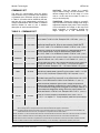
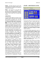
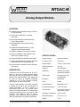
Weeder Technologies WTDAC-M VOLTAGE - Sets the voltage on a specific output channel using 0.01-volt resolution. The desired voltage can be in the range of -10.00 volts to +10.00 volts and is listed in 1/100 of a volt (no decimal point). COMMAND SET The host PC communicates with the Analog Output Module using a command set comprised of standard ASCII character strings as depicted in Table 2. A function can be initiated by the host and then left to be independently executed. All voltage representation data is listed in standard decimal notation for ease of use. A detailed description of each command follows. TRAPEZOID - Ramps the voltage on a specific output channel to a desired voltage level using a trapezoidal shaped slope profile. After reception of this command, the voltage on the output will begin increasing or decreasing towards the target voltage at a rate determined by TABLE 2: COMMAND SET TITLE COMMAND DESCRIPTION VOLTAGE V chn value Sets the voltage on an output channel. chn = A-D, value = 0 to ±1000 and is listed in 1/100 of a volt. Example: 825 = 8.25 volts. (Note 3, 4) TRAPEZOID T chn value Ramps the voltage on an output channel to a desired level using a trapezoidal shaped profile. Slope is determined by RAMP-RATE. chn = A-D, value = 0 to ±1000 and is listed in 1/100 of a volt. (Note 5) S-CURVE S chn value Ramps the voltage on an output channel to a desired level using an S-curve shaped profile. Slope is determined by RAMP-RATE. chn = A-D, value = 0 to ±1000 and is listed in 1/100 of a volt. (Note 5) PADDING P chn value Sets the magnitude of the curvature used in the S-CURVE function for a specific channel. chn = A-D, value = 1 to 3. Default = 2. (Note 3, 4) RAMP-RATE R chn value Sets the ramp rate used in the TRAPEZOID and S-CURVE functions for a specific channel. chn = A-D, value = 1 to 255 and is listed in 1/100 of a volt/sec. Example: 125 = 1.25 V/sec. Default = 50. (Note 3, 4) WAIT W value Loads an internal timer which will signal the host when expired. Allows time-derived, steady-state outputs in cyclic routines. value = 1 to 255 and is in 1/10 of a second. Example: 205 = 20.5 seconds. (Note 5) DEFAULT D chn value Sets the default voltage level for a specific output channel which will be loaded upon power-up, brown-out or an external reset. chn = A-D, value = 0 to ±1000 listed in 1/100 of a volt. Default = 0. (Note 3, 4) CALIBRATE C chn v1 v2 Takes the actual measured values of two voltage set-points and computes the calibration coefficients for a given channel. chn = A-D, v1 is the measured voltage after writing 800 to the output channel, v2 is the measured voltage after writing -800 to the output channel. All values are listed in 1/100 of a volt. Example: 825 = 8.25 V. (Note 3, 6) ECHO X value Turns on or off the reception confirmation echo. Value = 0 or 1. 0 = off, 1 = on, default = 1. If value omitted, reads the current setting. ERROR ? This character will be returned after an invalid command or variable. RESET ! This character will be returned after a power-on reset, or brownout. Note 1: All command strings sent to the data module should be preceded with the header character (see Table 1), and terminated with a carriage return. All responses from the data module will also appear in this format. Note 2: Any spaces shown above in the listing of the command strings are for clarity only. They should not be included in the actual transmission from the host, nor expected in a response from the data module. Note 3: If ECHO is on, after successful execution this command will be echoed back to the host in the same format as received. Note 4: If value is omitted, reads the current setting which will be returned to the host in the same format as above. Note 5: After this function has been completed, the command will be echoed back to the host in the same format as received. Note 6: The data module has been calibrated at the factory, it is not necessary to perform this operation prior to use. Copyright 2000-2006 by Weeder Technologies Page 3 Rev. F