1
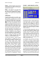
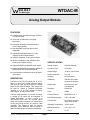
Weeder Technologies WTDAC-M ERROR - Any data string sent from the host containing the correct header character but an invalid command or variable will be responded to with this error indicator. FIGURE 1: MODCOM APPLICATION RESET - Upon power-up or any other reset condition, this indicator is transmitted to the host. Note, all user configuration and calibration data is stored in non-volatile memory. Therefore, a reset or loss of power will not corrupt these settings. OPERATION To hook the data module to a host PC, use a standard RS-232 cable with male and female DB9 connectors on opposite ends. This cable should be wired straight through (pin to pin) with no crossover of the data lines. In other words, not a null modem cable. Connect a suitable DC power source to the + and - terminals of the data module. It is highly recommended to use an ungrounded AC adapter such as that which is available from Weeder Technologies. This will provide isolation and prevent ground loops which are commonly created if the power supply and computer are grounded at different points. box will pop up which you can use to type in the commands from Table 2, transmit them directly to the data module, and see the response coming back. Use this dialog box to familiarize yourself with the command set and to experiment with the various features supported by the module. The experience gained here is significant since these are the same command strings you will use when setting up the other objects in ModCom. When the data module is first powered up, the red LED will flash briefly. This indicates that the on-board microcontroller has booted up, successfully completed its internal diagnostic test, and has transmitted the reset character to the host to signal that it is up and running. The red LED will also flash anytime the module receives or transmits any data packet, thus making it a valuable diagnostic tool when troubleshooting communications problems. To control the Analog Output Module, start with the sample application "WTDAC.mod" which can be found in the ModCom subfolder called "Samples". After this file is opened, it will appear as shown in Figure 1. To start the main run-loop, click on the green toolbar button at the top of the screen. At this point, you can move the two Slider Controls to adjust the voltages on channels A and B in real time. The current voltage will be shown in the window at the bottom of each Slider Control. An easy-to-use Windows™ software package called "ModCom" is available and can be downloaded from Weeder Technologies' web site. This program will allow the user to quickly set up custom buttons which transmit commands, custom windows that poll for data, and a variety of other screen objects such as slider controls, event counters & timers, bar-graph level indicators, button selection arrays, and more. In addition, conditional statements can be set up to take action when specific events or conditions are met, sequences can be written and then called by other screen objects during run-time, and data can be logged to a file automatically at user-defined intervals. This application also provides Push Buttons which transmit commands to ramp the voltage on channel C to a number of different target values. The Rocker Switches can be used to modify the ramping configuration. Channel D is set aside for a complex cycling routine which is controlled by a Sequence called "Cyclic". Once started, this Sequence will run continuously until clicking on the "Stop" button. The counter will increment each time a full cycle has completed. To understand how this application works, first halt the run-loop by clicking on the red toolbar button at the top of the screen, then right-click on any screen object to view its properties. The Sequences can be accessed by going to the <Run-Loop> menu item at the top of the screen Once ModCom is installed and running, go to the <Communicate> menu item at the top of the screen and click on <Send/Receive>. A dialog Copyright 2000-2006 by Weeder Technologies Page 5 Rev. F