1
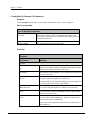
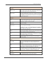
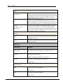
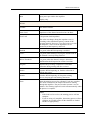
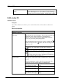
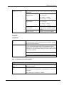
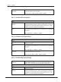
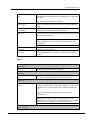
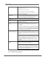
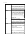
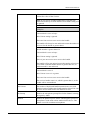
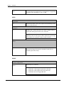
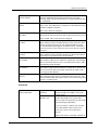
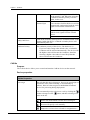
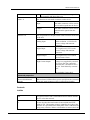
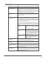
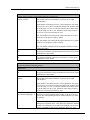
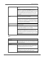
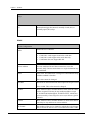
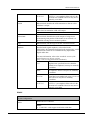
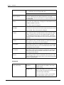
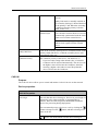
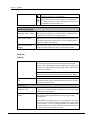
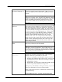
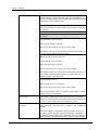
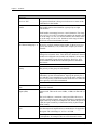
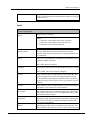
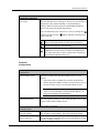
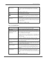
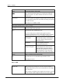
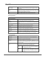
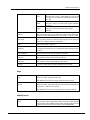
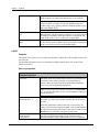
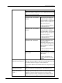
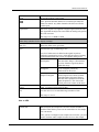
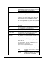
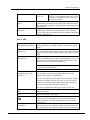
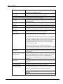
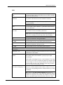
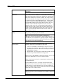
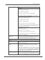
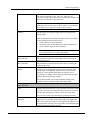
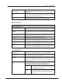
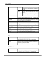
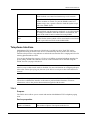
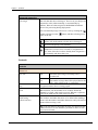
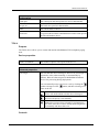
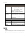
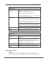
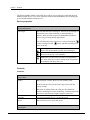
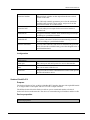
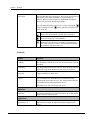
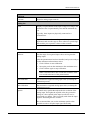
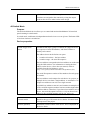
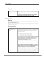
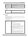
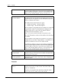
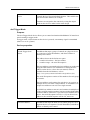
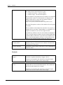
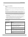
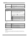
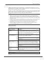
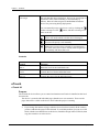
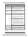
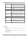
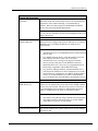
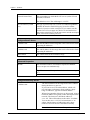
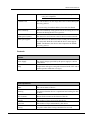
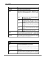
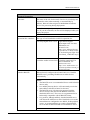
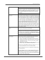
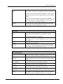
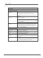
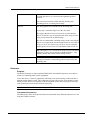
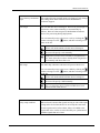
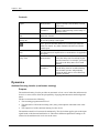
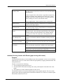
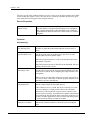
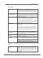
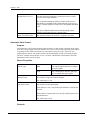
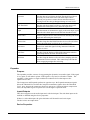
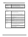
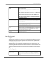
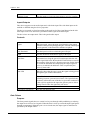
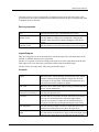
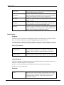
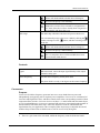
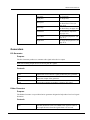
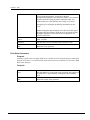
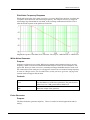
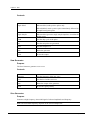
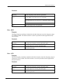
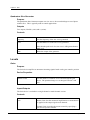
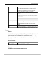
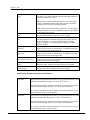
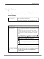
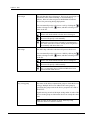
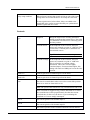
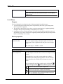
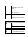
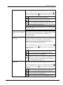
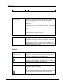
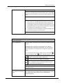
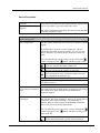
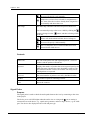
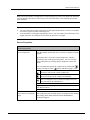
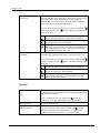
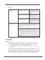
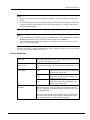
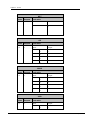
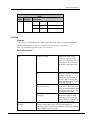
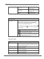
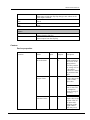
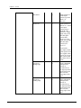
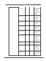
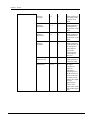
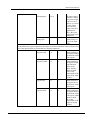
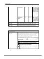
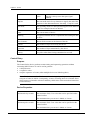
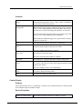
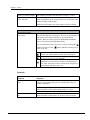
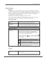
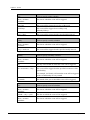
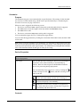
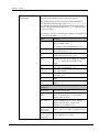
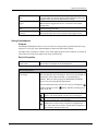
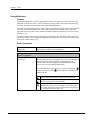
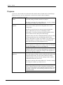
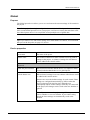
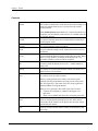
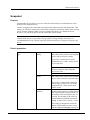
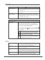
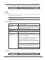
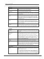
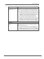
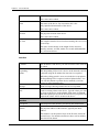
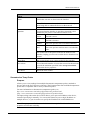
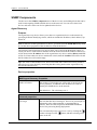
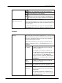
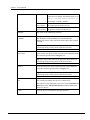
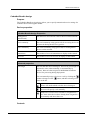
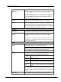
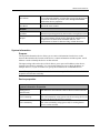
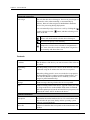
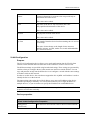
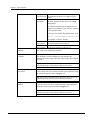
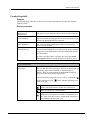
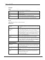
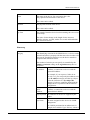
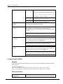
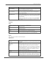
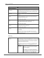
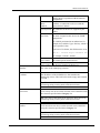
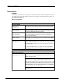
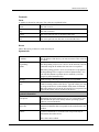
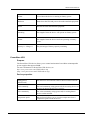
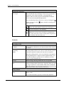
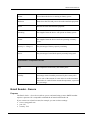
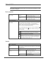
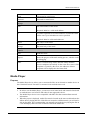
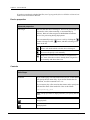
NWare Device Reference
Bypass
Bypasses the AGC gain stage. The Gain Change Meter
continues to operate as though the device were active.
Note: When the bypass is engaged, the AGC continues to
compute as the gain changes, and although this computed gain
is not applied to the signal passing through the device, the gain
change meter continues to function as if bypass were not
engaged.
Response Time
Determines how fast the AGC adjusts the gain in response to a
change in the side chain signal level.
Threshold Level
The Threshold level and associated logic is intended to detect
pauses in speech and suspend operation of the AGC during
these pauses. If this feature were not provided, the AGC would
eventually turn up a silent input to the Maximum Gain setting.
When the RMS input level falls below the threshold level and
Gain Recovery is switched off, the AGC enters a frozen state. In
this state, the gain through the device will longer be updated
based on the input signal level. With Gain Recovery enabled,
the gain applied to the input signal gradually returns to unity at
the rate determined by recovery time setting.
Tip: For most applications, the threshold level should be set so
that the quietest valid source level is above the point where the
AGC would enter the frozen state by at least 6 dB. An input
with no source (such as an open microphone channel) being fed
into the AGC should cause the AGC to either remain frozen or
return to unity.
When properly set, only a true source (not background noise)
will cause the AGC to become active (as shown by the Below
Threshold Indicator).
State
Indicates the current status of the AGC.
When Recovery is lit, the gain is in the process of returning to
unity.
Maximum Gain
This is the maximum level of the gain that the AGC provides.
This prohibits the AGC from applying so much gain to a quiet
source that problems such as feedback arise.
Note: There is no limit to the amount of attenuation the AGC
can produce.
Ratio
May 28, 2015
Sets the attenuation ratio to be applied to the input signals
below the threshold, up to the maximum attenuation. For
Version 1.7.2.3
197