
1
0 SAFETY PRECAUTIONS 0
(Read these precautions before using.)
When using Mitsubishi equipment, thoroughly read this manual and the associated manuals introduced in
this manual. Also pay careful attention to safety and handle the module properly.
These precautions apply only to Mitsubishi equipment. Refer to the user’s manual of the CPU module to
use for a descriptionof the PLC system safety precautions.
These 0 SAFETY PRECAUTIONS 0 classify the safety precautions intotwo categories:“DANGER” and
“CAUTION”.
r-----------------------------------
I
I
I
7
p
i
q
Procedures which may lead toa dangerous condition and cause death or
injury
serious
properly.
out
carried
if not
Procedures which may lead toa dangerous condition and cause superficia1 to medium injury, or physical damage only, if not carried out properly.
Depending on circumstances, procedures indicated by
results.
A
I
I
I
I
I
I
CAUTION may also be linked to serious
In any case, it is important to follow the directions for usage.
Store this manual in a safe place so that you can take it out and read it whenever necessary. Always
forward it to the enduser.
0
DANGER
0 When controlling (changingdata, program or operation status (remote RUN/STOP)in particular)
a PLC while it is running via a device suchas a personal computer connected to the special
function module, configurean interlock circuit inthe sequence program so that the safety of the
overall system is always maintained.
Especially, when performing the above control for a remote
PLC from an external device, troubles
occurring on thePLC side due to data communication error may not be handled immediately.
Determine error handling methods between the external device and the PLC CPU for when data
in the sequence procommunication errors occur, in addition to configuring a interlock circuit
gram.
ACAUTION
0 When installing AUI cables (transceiver cable)/coaxial cables, do not bundle them
or place them
or power lines. Keep themat least 1OOmm (3.94 inch) away from such cables.
close to main lines
Noise may cause erroneous operation.
[INSTALLATION PRECAUTIONS]
ACAUTION
0 Use the PLC in the environment given
in the general specifications sectionof this manual.
Using thePLC outside the rangeof the general specifications may result
in electric shock,fire, or
erroneous operation or may damage or degrade the product.
0 Make sure to switch all phases
of the external power supply
off when installingor placing wiring.
If you do not switchoff the external power supply,it will cause electric shockor damage to the
product.
0 Make sureto switchall phases of the external power supply
off before mountingor removing the
or may
module. If you do not switchoff the external power supply, it may result in electric shock,
damage the product.
0 Insert the tabsat the bottom of the module into the mounting holes in the base unit before installing the module. (Modules in AnS series, make sure screws are securely tightened to base unit
with specified toques.)
or the module to fall out.
Improper installation may cause erroneous operation, failure,
0 Tighten the screw within the range of specified toque.
If the screws are loose,it may result in fallout, short circuits,or malfunction.
Tightening the screws too far may cause damage to the screw and/or the module, resulting in
fallout, short circuits,or erroneous operation.
0 Do not touch the electronic partsor the module conductingarea.
It may cause erroneous operationor failure.
WIRING PRECAUTIONS]
ACAUTION
0 Do not connect the AUI cable when the module installation station's power is turned
on.
0 Be sure to fix communication cables and power cables leading from the module by placing them
in the duct or clamping them. Cables not placed in the ductor without clamping may hangor
shift, allowing them to be accidentally pulled, which may result in a module malfunction and
cable damage.
0 Perform correct pressure-displacement, crimp-contactor soldering for wire connections using
the tools specified by the manufacturers. Attach connectors to the module securely.
0 Tighten the terminal screws within the range of specified torque.
If the terminal screws are loose,it may result in short circuitsor malfunction.
Tightening the screws too far may cause damage to the screw and/or the module, resulting in
fallout, short circuits,or erroneous operation.
0 When detaching the communication cableor power cable from the module, do not pull the cable
portion. For cables with connectors, hold the connector at the junction to the module, then
detach it. For connectors without connectors, first loosen the screw at the junction, then detach
the cable.
it is connected to the module may cause a malfunction
or damage
Pulling the cable portion while
to the module and cable.
.
.
A CAUTION
0 Be sure that cuttings, wire chips,or other foreign matter do not enter the module.
Foreign matter may start a fire
or cause an accidentor erroneous operation.
[STARTING AND MAINTENANCE PRECAUTIONS]
0
DANGER
0 Do not touch the terminals while the electricity is on.
Doing so could cause erroneous operation.
0 Make sure to switchall phases of the external power supply off before cleaning
or re-tightening
screws.
or erroneous operation of
If you do not switch off the external power supply, it will cause failure
the module.
or erroneous operation.
If the screws are loose, it may result in fallout, short circuits,
Tightening the screws too far may cause damage to the screws and/or the module, resulting in
fallout, short circuits, or erroneous operation.
ACAUTION
0 Do not disassemble or rebuild the module.
It may cause failure, erroneous operation, injury,
or fire.
0 Make sure to switch all phases of the external power supply off before mounting
or removing the
module.
it will cause failureor erroneous operation of
If you do not switch off the external power supply,
the module.
[OPERATING PRECAUTIONS]
0
Do not
write data in the "system area"
in the buffer memoryof the special function module.
Also, of the output signals directed to the special function module from the PLC CPU, do not
output (switchon) the signals that are "use-prohibited".
a "use-prohibited"
If data is written to the "system area" or output is performed with respect
to
PLC system.
signal, it may result in the malfunction of the
ACAUTION
0 Before performing the control of thePLC in operation (especially changing data, program, and
operation status (remote RUNISTOP)) by connecting a personal computer, etc. to the special
if the overall safety is maintained.
function module, read the manual carefully and confirm
data, program, or the operation status may result
Failure to perform correct operations to change
or an accident.
in system malfunction, machine damage,
I
I
’
0 Remote RUN/STOP for the module installation station’s PLC CPU
is recommended to use the
“Data Exchange during PLC CPU S T O P function after throughly reading the manual.
If the remote RUN/STOP is executed without using the “Data Exchange during PLC CPU STOP”
the PLC CPU to the module goesOFF and the communication
function, the output signal from
line is disconnected (close processing).
As a result, all data transmission from other nodes, including status control of the PLC CPU,
becomes impossible.
[DISPOSAL PRECAUTIONS]
ACAUTION
I
0 When
disposing
of
product,
this
handle
it as industrial
waste.
I
REVISIONS
The manual number is given on the bottom left of the back cover.
Revision
Wnt Date
'Manual Number
3ep. 1996
SH(NA)-3598-A
First edition
4ug. 1997
SH(NA)-3598-B
.Addition]
a
SAFETY PRECAUTIONS. Item 4.7.1 CAUTION. Item 5.3.1'3,
Item 5.4.5 (2),Item 10.2.8 D P o i n t (4),Item 10.3.6
Point (4),
Item 13.1.1 (Error code: 7010 H), Appendix 7.2, Appendix 7.3
Correction
1
SAFETY PRECAUTIONS, CONTENTS, MANUALS, Chapter 1 Point,
item 2.1, Item 2.3 m ( a ) , Remarks,
Item 3.3
Item 1.2
Item 3.4.1, Item 3.7.2 Point, Item 4.4, 4.5.1, 4.6.1, 4.7.2, Item 5.2 Point
( l ) ,Item 5.3.1, 5.4.2, 5.4.3, 5.4.4,
Item 5.4.5 (2),Item 5.5.3,5.6.1, 5.6.3,
7.3.1, 7.3.3, 10.1.3, 10.4.1, 10.5.1, 10.6.4,
Item 13.1.1 (Error Code:
AOOFH), Item 13.2, Appendix 3 (ln(b), Appendix 7.1, Appendix 8
m,
Sep. 1998
SH(NA)-3598-C
m,
m,
Addition1
SAFETY PRECAUTIONS, Chapter1 Point (2), Item 2.3 (Remark (2)),Item
3.2, Item 5.1 rl),Item 9.2 (PLC CPU model), Item 10.4.1 (2), 10.5.3,
10.6.5 (1) (b), Appendix6, Appendix10
I Correction]
SAFETY PRECAUTIONS, Chapter 1 (Table), Item 1.2 (9),1.3, 1.4,Item
2.2, 2.3 ((1)*1,(2),Point), Item 3.2, 3.3, 3.4.2, 3.5.2,3.6.1 (Important, (3),
(4),(lo),(12)), 3.7.1,Item 4.2, 4.3.2, 4.4, 4.5.1, 4.7.2, 4.7.3,Item 5.1
Point, 5.3.1 (Table, (2), ( l l ) , *1, *3,point), 5.3.2, 5.3.3,5.4.2, 5.4.3,
5.4.4, 5.5.2 (4), (7),5.6.3, Item 6.1 (2) Point, 6.2.1 (l), 6.2.2,Item 7.1 (2)
Point, 7.2.1 (l),7.2.2 (2), 7.3.2, Item 8.2.1 (1) 8.2.2 (1) Item 10.1.1 (1)
10,1,2(1), 10.1.3(4), 10.6.3(2),
l t e m l l . l (Point), 11.2(1),Item 13.1.1
(7004H,AOOEH),13.2, Appendix 7.2 (Program), Appendix 7.3 (Program),
Appendix 8
Dec. 1998
SH(NA)-3598-D
I Correction I
Contents (Appendix pages), Item 1.2 (6) (9),Item 4.5.1 (2), Item 5.3.1
(page 5-10 *2 and *3),5.4.5 (Program), Appendix7.2 (Program), 10 (3)
LAddition
I
Contents (Appendix 1l ) , Item 13.2 (Point), Appendix 1 1
~~
'Manual Number
SH(NA)-3598-E
Revision
1Over all (program examples), SAFETY PRECAUTIONS, Item 1.3, Item 2.3((1)
Remark, (2), Point), Item 3.1, 3.2, 3.5.3, 3.6.1, 3.6.2(2)(7), 3.7.2, Item 4.4,
4.5.1,ltem5.2(Point),5.3.1,(*1
for(7)),5.4.1 (1)(2),5.4.2,5.4.3,5.4.4,5.5.2(5),
5.5.4, Item 6.2.3(3), Item 8.2.2, 8.2.4, Item 9.1.2(4), 9.1.3(4),9.2'4 to '7,
9.4(7), Item 10.2.1((2),* l ) ,10.4.1(2), 10.6.7, Item 13.1.1, 13.2(Point)
1Item 1.2(10), Item 3.2, Item 5.4.3(2) Remark, 5.4.4,Remark(3), Item 6.1.1
Remark, 6.1.2 Remark, 6.3.1 (7), Item 7.1.1 Remark, 7.1.2 Remark, Item
8.3.1(3), Item 9.4(6), Item 13.2*1
This manual does not imply guarantee or implementation right for industrial ownership or implementation of
other rights. Mitsubishi Electric Corporation is not responsible for industrial ownership problems causedby use
of the contents of this manual.
0 1998 MlTSUBlSHl ELECTRIC CORPORATION
Thank you for purchasing the Mitsubishi programmable controllerMELSEC-A Series .
Before using your MELSEC-A Series. pleaseread this manual thoroughly to gain an understanding of the functions
and performances of the A Series PLC so that the equipment is used to its optimum .
OUTLINE OF CONTENTS
(COMMON SECTION)
1. GENERALDESCRIPTION
2.
3.
4.
5.
..............................................................................................
SYSTEMCONFIGURATIONS ........................................................................................
SPECIFICATIONS ..........................................................................................................
SElTlNGS AND PROCEDURES UP TO OPERATION ....................................................
PROCEDURES FOR EXCHANGING WITH REMOTENODES ........................................
1- 1 to 1-12
2- 1 to
3- 1 to
4- 1 to
5- 1 to
2- 7
3-27
4-15
5-47
(FIXED BUFFER EXCHANGE SECTION)
6 . FIXEDBUFFEREXCHANGEWITH
PROCEDURE ..........................................................
7 . FIXEDBUFFER EXCHANGE WITHOUT PROCEDURE ...................................................
6- 1 to 6-15
7- 1 to 7-17
(RANDOM ACCESS BUFFER EXCHANGE SECTION)
8 . RANDOMACCESSBUFFER EXCHANGE .....................................................................
8- 1 to 8-17
(READINGMIRITING DATA IN THE PLC CPU SECTION)
READINWRITING DATA IN THE PLCCPU EXCHANGE .............................................
9.
10. WHEN CONDUCTION READWRITE OF DATA IN THE PLC CPU ...............................................
9- 1 to 9-18
10-1 to 10-1 09
(SPECIAL FUNCTIONS SECTION)
11 . WHEN SE-TTING A SUBNET MASK .............................................................................
12. WHENUSINGROUTERRELAY FUNCTIONS ..............................................................
11- 1 to 11- 5
12- 1 to 12- 4
(TROUBLESHOOTING SECTION)
13. TROUBLESHOOTING ..................................................................................................
13- 1 to 13-19
APPENDICES
...........................................................................................................................
A-1 to A-41
ABOUT THIS MANUAL AND RELATED MANUALS
1
COMMON SECTION (CHAPTERS1 TO 5)
CHAPTER 1. GENERAL
DESCRIPTION
1- 1 t o l - 1 2
1.1SoftwareConfiguration
............................................................................................................
..................................................................................................................................
1.2Features
AJ71 E71 ......................................................................................................
1.3 Comparison with
1.4 Terms, Abbreviations, and Terminology Used in This Manual ...................................................
CHAPTER
2
. SYSTEM
CONFIGURATION
2- 71 to 2-
2.1
Overall Configuration ................................................................................................................
.................................................................................................................
2.2SupportedSystems
2.3
DevicesRequired for Network Configuration ............................................................................
3 CHAPTER
3.1
3.2
3.3
3.4
3.5
3.6
3.7
1- 3
1- 4
1-11
1-12
. SPECIFICATIONS
3-
2- 1
2- 2
2- 4
1 to 3-27
General Specifications .............................................................................................................
Performance Specifications ......................................................................................................
Data Codes during Communication and Exchangeable
Data Amount ......................................
Functions .................................................................................................................................
3.4.1 List of Functions ..........................................................................................................
3.4.2 Relationship between Communication Remote Node and Added Functions for Each
Communication Function ............................................................................................
Send and Receive Processing .................................................................................................
3.5.1 Message Division andDataLength .............................................................................
33333-
3.5.2 Continuous Processing
Over the Same Connection ....................................................
3.5.3 Conditions
for Issuing a Forced Disconnect ................................................................
I/O Signals for the PLC CPU ....................................................................................................
3.6.1 Listof I/O Signals ........................................................................................................
3.6.2 Detailed Explanation of I/O Signals ..............................................................................
Buffer Memory .........................................................................................................................
3.7.1 Buffer Memory Applications ........................................................................................
3- 9
3- 9
3-1 0
3- 10
3-1 1
3-21
3-2 1
3-22
3.7.2
List of Buffer memory Allocations
................................................................................
CHAPTER 4 . SETTINGS ANDPROCEDURESUPTOOPERATION
1
2
4
6
6
3- 7
3- 8
3- 8
4- 1 to 4-1 5
4.1AbbreviatedProceduresUptoOperation
.................................................................................
4.2 Names of Parts ........................................................................................................................
4.3Switch
Settings ........................................................................................................................
4.3.1OperationMode
Settings ............................................................................................
4444-
4.3.2 ExchangeCondition Settings ......................................................................................
4.4 Description
of Display LED's Display ........................................................................................
4- 4
4- 5
1
2
3
3
4.5
4.6
4.7
4.8
4.9
Mounting and Installation .........................................................................................................
..................................................................................................
..............................................................................................
Self-Diagnostic Test .................................................................................................................
.....................................................................................................
4.6.1Self-LoopbackTest
4.6.2 RAM Test ....................................................................................................................
4.6.3 ROM Test ...................................................................................................................
Connecting to Network ............................................................................................................
4.7.1Connection
Precautions ..............................................................................................
4.7.2Connectingto
10BASE5 .............................................................................................
4.7.3 Connecting to
1OBASE2 .............................................................................................
Loopback Test .........................................................................................................................
Maintenance and Inspection ....................................................................................................
4.5.1
Handling Precautions
4-6
4.5.2
Installation Environment
4-7
CHAPTER 5. PROCEDURES FOR EXCHANGINGWITHREMOTENODES
5.1
5.2
5.3
5.4
5.5
5.6
4- 6
4-8
4-8
4-9
4-10
4-11
4-11
4-12
4-13
4-15
4-15
5- 1 to 5-47
Overview of Exchange Procedures...........................................................................................
5-1
Connecting and Disconnecting Communication
Lines .............................................................. 5 - 4
initial Processing and End Processing...................................................................................... 5 - 5
5.3.1 Data for Initial Processing ............................................................................................ 5 - 5
5.3.2 Initial Processing and End Processing Procedures ......................................................
5-10
5.3.3 Example Program .......................................................................................................
5-11
Communication Line Open and Close...................................................................................... 5-12
5.4.1 Data for Opening ......................................................................................................... 5-13
5-21
5.4.2 Communication
Line Open Processing Procedure ......................................................
5.4.3 Communication Line Close Processing Procedure ...................................................... 5-23
5.4.4 Pairing Open Communication Line Open Processing and Close Processing Procedures .... 5-27
5.4.5 Example Program ....................................................................................................... 5-31
5-35
Exchange State Storage Area ..................................................................................................
5-35
5.5.1 Initial Processing State Storage Area ...........................................................................
5.5.2 Exchange State Storage Area ..................................................................................... 5-36
5.5.3 Error Log Area ............................................................................................................ 5-38
5.5.4 Protocol
Status Storage Area ...................................................................................... 5-39
Data Exchange during the PLC CPU is Stopped ...................................................................... 5-40
5-40
5.6.1 Settings for Continuing Data Exchange .......................................................................
5-41
5.6.2 Functions for Which Continuing Data Exchange is Possible .........................................
5.6.3 Relationship between the Setting and Data Exchange during the PLC CPU is Stopped ...... 5-41
FIXED
BUFFER
EXCHANGE
SECTION
(CHAPTERS
1
6 AND 7)
CHAPTER
6
.
6.1Control
6.1 -1
Format .........................................................................................................................
Transmission ControlMethod .....................................................................................
FIXED
BUFFER
EXCHANGE
WITH PROCEDURE
6- 1 t06-15
6.2
6.1.2Reception
Control Method ..........................................................................................
Data Format .............................................................................................................................
6- 1
6- 3
6- 5
6-7
6.3
6.2.1 Format When Exchanging with Binary Code ................................................................
6.2.2 Format When Exchanging with ASCII Code .................................................................
6.2.3 Exchange DataItem Contents .....................................................................................
Programming ............................................................................................................................
6- 7
6- 8
6- 9
6-11
6.3.1 Programming Creation Precautions .............................................................................
6.3.2Program
Creation Procedure ......................................................................................
6.3.3 Example Fixed Buffer Exchange Program (With Procedure) .........................................
6- 1 1
6-1 2
6-1 3
CHAPTER 7. FIXED
BUFFER
EXCHANGE
7- 1 t07-17
WITHOUT PROCEDURE
7.1Control
Format .........................................................................................................................
7-1
7.1.1 Transmission Control Method ..................................................................................... 7-3
7.1.2ReceptionControlMethod
.......................................................................................... 7- 4
7-6
7.2
Data Format .............................................................................................................................
7-6
7.2.1 Format during Exchange .............................................................................................
7.2.2 ExchangeDataItem Contents ..................................................................................... 7- 6
7- 8
7.3 Simultaneous Broadcast Communication When Using UDP/IP ................................................
7.3.1 Simultaneous BroadcastCommunicationTransmission .............................................. 7-8
7.3.2 Simultaneous BroadcastCommunicationReception ................................................... 7- 9
7.3.3 Precautions When Using Simultaneous Broadcast Communications Functions ........... 7-1 1
7.4Programming
........................................................................................................................... 7-12
7.4.1 Precautions When Creating Programs ......................................................................... 7-1 2
7- 1 4
7.4.2 Program Creation Procedures .....................................................................................
7-15
7.4.3 Example Fixed Buffer Exchange Program (Without Procedure) ....................................
I
RANDOM
ACCESS
BUFFER
EXCHANGE
SECTION
(CHAPTER
CHAPTER 8. RANDOM
ACCESS
BUFFER
EXCHANGE
I
8)
8- 1 to 8-17
8.1Control
Format .........................................................................................................................
8.1.1 Control Method When There is a Read Request from a Remote Node ........................
8.1.2 Control Method When There is a Write Request from a Remote Node ........................
8.2Data
Format .............................................................................................................................
8.2.1 FormatWhen Exchanging with Binary Code ................................................................
8.2.2 Format When Exchanging with ASCII Code .................................................................
8.2.3 Exchange DataItem Contents .....................................................................................
8.2.4 Example Command and Response Format .................................................................
8.3Programming
...........................................................................................................................
8.3.1 Program Creation Precautions ....................................................................................
8.3.2 Program Creation Procedure ......................................................................................
8- 1
8- 2
8- 3
8- 4
8- 4
8- 6
8- 8
8-10
8-14
8-14
8-1 6
READINGMRITING DATA IN THE PLC CPU SECTION (CHAPTERS
9 AND 10)
CHAPTER 9. READlNGMlRlTlNG DATA IN THE PLCCPU EXCHANGE9-1
tO9-18
Control Method ........................................................................................................................
9-1
9.1.1 Exchanging with the
PLC CPU Installed in the Ethernet Interface Module ....................
9.1.2 Exchanging with the PLC CPU in the Network System ................................................
9.1.3 Exchanging with the PLC CPU in the Data Link System ..............................................
9-2
9-3
9-8
9.1 .4 Exchanging with the PLC CPU in Mixed Systems ........................................................
9.2List
of E71 Commands and Functions .....................................................................................
9.3 PLC CPU Operation during Data Exchange .............................................................................
9-11
9-12
9-17
.....................................................................................................
9-18
9.1
9.4
DataExchangePrecautions
CHAPTER10. WHEN CONDUCTING READWRITEOF DATA IN THE PLC CPU10-1 to 10-109
10.1 Data Format ............................................................................................................................
10.1.1 Format When Exchanging Using Binary Code ............................................................
10-1
10-2
10.1.2 Format When Exchanging Using ASCII Code ............................................................. 1 0 - 3
10.1.3 Exchange Data Item Contents .................................................................................... 1 0 - 4
10.1.4 Thinking Regarding Transmission Data....................................................................... 1 0 - 8
10-12
10.2 Device Memory Readwrite ...................................................................................................
10.2.1 Command and DeviceRange ................................................................................... 10- 12
10.2.2 Bit Unit Batch Read ................................................................... (00)
........................ 10-15
10.2.3 Word Unit Batch Read ............................................................... (01) ........................
10-17
10.2.4 Bit Unit Batch Write ....................................................................
(02) ........................ 10-21
10.2.5 Word Unit Batch Write ...............................................................
(03)........................ 10-23
10.2.6 Bit Unit Test (Random Write) ......................................................
(04) ........................
10-27
10.2.7 Word Unit Test (Random Write) .................................................. (05) ........................
10-29
10.2.8 Device Memory Monitor............................................................. (06 to 09) ...............10-32
10-40
10.3 Extension File Register Read and Write ..................................................................................
10.3,l Commands and Addresses ....................................................................................... 10-40
10.3.2 Precautions When Readingwriting Extension File Registers ..................................... 10-41
10-42
10.3.3 Extension File Register Batch Read ............................................ (17) ........................
10-44
10.3.4 Extension File Register Batch Write ............................................ (I 8) ........................
(1
9)
........................
10-46
10.3.5 Extension File Register Test (Random Write)...............................
10.3.6 Extension File Register Monitor .................................................. (IA, 1B) ................. 10-48
10.3.7 Extension File Register Direct Readwrite ................................... (38, 3C) ................. 10-53
10-59
10.4 Special Function Module Data Read and Write ......................................................................
10-59
10.4.1 Command and Data Item Specification Method ........................................................
10.4.2 Special Function Module Buffer Memory Read ........................... (OE) ........................
10-65
10.4.3 Special Function Module Buffer Memory Write ........................... (OF) ........................
10-67
10.5 Remote RUN/STOP and CPU Model Name Read.................................................................. 10-69
10.5.1 Commands and Functions ........................................................................................ 10-69
(13, 14) .................. 10-70
10.5.2 Remote RUN/STOP ...................................................................
10.5.3 PLC CPU Model Name Read ..................................................... (15) ........................
10-72
10-74
10.6 Sequence Program ReadNVrite .............................................................................................
10-74
10.6.1Precautions When Readingwriting Programs ...........................................................
10.6.2Program Readwrite ................................................................................................. 10-75
10.6.3 Parameter Memory Read, Write, and Analysis Request .............(10 to 12) ............... 10-77
10.6.4 Sequence Program ReadMlrite ..................................................
10.6.5 Microcomputer Program ReadNVrite ..........................................
10.6.6 Comment R e a W r i t e
................................................................
................................................
10.6.7 Extension Comment ReadMlrite
10.7 Loopback Test
(OA to OD) .............. 10-83
(1E to 21) ............... 10-91
(1C, 1D) ................. 10-97
(39. 3A) ................ 10-102
(16) ......................
10-107
SPECIAL FUNCTIONS SECTION (CHAPTERS11 AND 12)
.
11- 1 t o l l - 5
CHAPTER 11 WHEN
SETTING
SUBNET
A MASK
11.1 Subnet Mask .........................................................................................................................
1 1.2 Data for Setting the Subnet Mask ..........................................................................................
11.3 Ethernet IP Address ...............................................................................................................
CHAPTER 12. WHEN
USING
ROUTER
RELAY
FUNCTIONS
11- 1
11- 3
11- 4
12- 1 to
12-
12.1Router Relay Functions ..........................................................................................................
12.2 Exchangeable Functions and Settable Range Using Router Relay Functions ..........................
12.3 Summary of Router Relay Processing ....................................................................................
12.4 Data for Using Router Relay Functions ...................................................................................
4
12- 1
12- 2
12- 2
12- 3
TROUBLE SHOOTINGSECTION (CHAPTER13)
CHAPTER 13. TROUBLESHOOTING
13- 1 to 13-19
13.1 List ofError Codes .................................................................................................................
13.1.1 End Codes Returned to the Remote Node during Data Exchange
Error Codes Stored in the Buffer Memory..................................................................
13.1.2 Error Codes Returned to the Remote Node by Reading and Writing Data in the PLC
CPU .........................................................................................................................
13.2 Troubleshooting Flow .............................................................................................................
13.2.1 Transmission Error during Fixed Buffer Exchange
(Common for Both with Procedure/without Procedure) .............................................
13.2.2 Reception Error during Fixed Buffer Exchange
(Common for Both with Procedure/without Procedure) .............................................
13.2.3 Error during Random Access Buffer Exchange ..........................................................
13.2.4 Error When Readingwriting Data tothe PLC CPU ....................................................
..
13- 1
13- 2
13- 9
13-10
13-1 2
13-14
13-1 6
13-18
A-
APPENDICES
Appendix 1
1 to A-41
Substitutingfrom AJ71 E71 (Previous Product) .........................................................
Appendix 1.1
Module Compatibility
..........................................................................................
A- 1
A- 1
Appendix1.2Program
Utilization .............................................................................................A1
Appendix 1.2.1 Remote Node Side Program Utilization .......................................................... A- 1
Appendix 1.2.2 Sequence Program Utilization ........................................................................
Appendix 2
Adding the Ethernet Interface Module to the Existing System ..................................
Appendix3ProcessingTime
......................................................................................................
ASCII CodeTable ....................................................................................................
Appendix 4
A- 2
A- 2
A-3
A-10
.............................................................................................
Appendix 6
Diagram of External Dimensions ..............................................................................
Appendix 7
SampleProgram .....................................................................................................
Appendix 7.1 Program
for ReadingMlriting Data in the PLC CPU .............................................
Appendix 7.2 Sequence Programs
for All Functions (Shared Sequence Program) ....................
A-I0
Appendix 5
ReferenceDocuments
A-11
A-13
A-13
A-21
Appendix 7.3
Program for ReadingNVriting Data in the PLC CPU (Remote Node Side Program) .... A-26
Appendix8
Difference between Ethernet and IEEE802.3 ............................................................ A-31
E71Support's ICMP Protocol .................................................................................. A-31
Appendix 9
Appendix 10
When Using the Ethernet Interface Module with a QnA Type PLC ............................ A-32
A-33
Appendix11
MELSEC CommunicationSupportSoftware Tool ....................................................
Appendix 1 1. 1
Appendix 1 1.2
Appendix12Index
Outline of basic communication supporttool ......................................................
Examples of using basic communication support tool........................................
.......................................................................................................................
A-33
A-35
A-38
MANUALS
Following is a list of manuals related to the Ethernet Interface Module.
Related Manuals
Manual Name
Model AJ71E71-S3 Ethernet Interface Module User's Manual
[Hardware)
This manual explains the procedures for setting settings and startingup
with a system configuration, unit specifications, and operation whenthe
module is used and gives the external dimensions of the unit.
(Packaged with theAJ71 E714 3 )
Manual No.
fModel Code]
18-66687
(13J854)
Model AI SJ71E71-B2-S3/A1 SJ71Rl -B5-S3 Ethernet Interface ModuleUser's Manual
[Hardware)
This manual explains the procedures for setting settings and startingup
with a system configuration, unit specifications, and operation when the
module is used and gives the external dimensions of the unit.
(Packaged with theAlSJ71 E71 -B2-S3 / AlSJ71 E71-65-S3)
MELSECNET and MELSECNET/B Data Link System Reference Manual
This manual gives an overview and the specifications for MELSECNET (11)
and MELSECNET/B and the procedures for setting the link parameters
and operation and troubleshooting.
Please read this manual when accessing other stations via data link systems.
18-66688
(13J855)
18-66350
(13JF70)
1 pLcl
to
MELSECNET/l 0 Network System Reference Manual
This systemgives an overview of and the specifications for the MELSECNET/
10 and the procedures for setting and operating the parameters, and explains about programmingand troubleshooting.
Please read this manual when accessing remote stations via the
QnA
MELSECNET/lO networksystem or when accessing another station using
data link instructions.
separately)(Sold
QWQ4AR
IB-66440
(13JE33)
SH-3509
IB-66620
l(13JF77)
1
16-66690
(13JF78)
I
COMMON SECTION
I
The common edition gives a summary ofthe functions and explains the features and system
configuration, module specifications,and data exchange when exchanging data with thePLC
CPU using a node external device via the Ethernet Interface Module.
Before using the Ethernet Interface Module, please read Chapters 1 through 5 once.
When booting up the system please follow the explanation in Chapter 4 to set the unit switch,
connect with externaldevices, and check operations,
Abbreviated procedures for booting up the unit are given in Item 4.1.
1. GENERAL
I GENERAL DESCRIPTION
This manual explains the Ethernet Interface Module specification, handling, and programming method
for connecting the computer to the A-series PLC, using Ethernet's TCPIIPor UDP/IP method.
@ Model AJ71E71-S3 Ethernet Interface Module (hereafter AJ71 E71 -S3)
Both 1OBASE5 (Ethernet) and1OBASE2 (Cheapernet) are supported and function as nodes on the
Ethernet.
To switch between the lOBASE5 and IOBASE2 interfaces, use the switch on the front of the
AJ71 E71-S3.
@ Model AI SJ71 E71-B2-S3 Ethernet Interface Module (hereafter
A1 SJ71 E71
-B2-S3)
Supports the IOBASE2 (Cheapernet)and functions as a node on the Ethernet.
@ Model AI SJ71 E71-B5-S3 Ethernet Interface Module (hereafter A1 SJ71
E71-B5-S3)
Supports the lOBASE5 (Ethernet) and functions asa node on the Ethernet.
Including these units in Ethernet makes it possible
to exchange data between the A-series PLC and the
computer and between QnA and A-series PLC.
_ _ _ _ ~
~
,..d
Remote
Node
1
1OBASES Comial Cable
Transceiver
U
%\
AUl Cable
Termmator
A-Senes
PLC
,
MELSECNET/lO
L
Fig 1.1
1
I
1
Connection Diagram Using 1OBASES (Ethernet)
I 1
Remote
Node
Remote
Node
I
I
1OBASE2 Coaxial Cable
P
E7 1
A-Series
PLC
MELSECNET/lO
~~~
Fig 1.2
~~~
~
~~~
~
Connection Diagram Using 1OBASEP (Cheapernet)
1-1
n
I. GENERAL DESCRlPTlON
MELSEC-A
When unpacking the Ethernet Interface Module be sure that one of either
of the following products is
included.
Please have the user make separate arrangements for parts and materials other than these (refer to
item 2.3)
Model AJ71 E71 -S3
Ethernet Interface
Module
I
Item
Product of hardware
version B or before
Product of hardware
version C or later
Product in the same package
Main module
1
Main module
module
I Main
1 each
I
i d z e r (UG-Z74/U)
(UG-Z74/U)
‘Model BNC T Adapter
I
Idule
~.
Main module
~ .
. .
Model A I SJ7 1E7 1-B2-S3 Ethrnet Interface Module
I Model BNC T Adapter (UG-274/U)
Model A1 SJ71 E71-B5-S3 Ethernet Interface Module 1 Main
Main module
module
~
~
~~~
Quantity
1 each
1
-Point
(1) This manual explains the functions and methods of use for the Ethernet Interface Modules
AJ71 E71-S3, AISJ7I E71-52-53, and AI SJ71 E71-B5-S3. In regards to the method forconnecting to Ethernet, please read the explanations corresponding 10BASE2or 10BASE5.
(2) Even though hardware specifications for the switches,1OBASE2 connector and other areasof
AJ71 E71-S3 have been changed in hardware version C or later, the functional and perforrnance specificatiorls in those areas are the same as the conventional products.
The user can
use the product just in the same manner as the conventlonal one.
(3) In this manual the general terms for the Ethernet interface module will be E71,
1OBASES, and
1OBASE2; and the general term for network will be Ethernet.
1-2
. ....
. ...... .. .
1. GENERAL DESCRIPTION
MELSEC-A
1.I Software Configuration
E71 supports the TCP/IP and the UDP/IP protocols.
, _ _ _ _ _ _ _ _ _ _ - - - - personalcomputer/work~tation _ _
__--
,_
__.
~
1
User program
$
8
8
,
1
1
A
8
8
V
Socket
TCP
UDP
UDP
-a
I
___-__---_____-_-----
1-7
PLC A-Series
,
1
,
~
~
1
,
I
I
1
'
,
1
1
1
,
,
Exchanges
stgnakusinga
set buffer.
I
1
8
,
1
1
1
1
,
,
,
,
1
1
1
1
pLc
FROMITO
,
1
8
1
1
1
Ethernet
CPU
,
,
4
'
IP
-
. _-.
,
1
$
System call
_ _ - - - - _ _ - - - - _ _- - .
,
.
Buffer memory
Exchanges
signdsustnga
random
access buffer.
TCP
8
IP
,
,
,
,
,
,
1
,
,
'
Exchanges
thePLC
CPU data
readdwrrtes.
:
1i
k
J
ICMP
Ethernet
1OBASE2
1OBASE5
1ORASE2
$. __
I--..--.-----.-..---..---._ _ _ _ _ _ _ _ _ _ _' _ _
_ _. _
_
-_
_ -_
- -_
__
_
---_
__ ___
-_
- ._
--- .-_
-__ _-_
--- -_
---_
- - - -_
- - -I
--------'
Fig 1.3
;
PLC CPU 1
1OBASE5
-.
SoftwareConfigurationDiagram
TCP (Transmissioncontrolprotocol)
This protocol retains the data reliabllity and correctness for the TCP protocol level.
Establishing a connection creates a theoretical connection asif a special line were created
between the nodes.
A maximum of 8 connections can be establishedat the same time and communication to
multiple buffers can be doneat the same time.
Data reliability is maintained by usinga check sum for PLC control and data read transmit
functions using the PLCNo.
The communication data flow can be controlled using window operations.
Supports a MAX SEGMENT option
12t/
UDP (Userdatagramprotocol)
This protocol retains the data reliability and correctness on the
UDP protocol level.
However if the data does not reach the target node it will not be retransmitted.
Because it is connectionless, high speed transmission is possible.
A check sumis used to increase the reliability of the transmitted data. However when greater
reliability must be maintained, use a user application or TCP.
a
IP (Internetprotocol)
Data transmlssions can be sent and received using the datagram format.
The transmitted data can be divided and reassembled
Routing options are not supported.
ARP (Address resolution protocol)
a
A broadcast is usedto find the Ethernet physical address from theIP address.
ICMP (Internetcontrolmessageprotocol)
Has a functionto transmit IP error messages.
Please referto the attachment for information regarding the ICMP option support type (ICMP
protocol).
Ethernet is the registered trademark of XEROX CO., LTD.
1OBASE2 is the formal way to say Cheapernet.
I
I
registered
There
nois trademark
Cheapernet.
for
1-3
I . GENERAL DESCRIPTION
MELSEC-A
1.2 Features
E71 is a unit used to connect the A-series PLCto the Ethernet.
By combining a A-seriesPLC in the Ethernet itis possible to construct a network system that combines
data link system/network with the Ethernet.
It is possible to conduct fixed buffer communication with a remote node and to read and write data
from the randon- access buffer exchange area from the
PLC CPU.
Fixed buffer exchange uslng TCP/IP or UDP/IP, random access buffer exchange, and reading and
writing data inside thePLC CPU (generaldata exchange) from a remote node is possible.
The main features of the E71 are explained below.
Selecting the exchange format and exchange
node units is possible (see Chapter 5 for
a detailed explanation)
@ Whether to use the TCP/IP or the UDP/IP communication protocols can be selected for
each remote node that exchanges data, and the communication line for the target remote
node can beset to open (communication line connect).
@ Eight communication lines can be open at the same time and data can be exchanged with
multiple remote nodes.
@ The relationship between the E71 data exchange and the selectable exchange formats is
shown below.
Exchange Function
With procedures
Exchanging uslng a fixed buffer
Without procedures
Exchange using a random access buffer
Readingwritingdata Inside the PLC CPU using requestsfrom
a remote node (General data exchange)
1-4
- ..
TC PA P
UDPAP
0
0
0
0
0
0
3
3
7. GENERAL DESCRIPTION
MELSEC-A
Data exchange while thePLC CPU is stopped is possible (Detailed explanation in Item
5.6).
0When conducting the following data exchange, the data exchange with remote nodes can
be continued evenif the PLC CPU installed in the E71 is stopped after the communication
llne is opened by the PLC program.
(Function that makes it possible to continue exchange when inSTOP status)
Exchange using random access buffer
Writingheading data inside the PLC CPU with a request from a remote node (general
data exchange)
' I n either case exchange can be continued using the communication protocol at the
time the communication lineis opened.
@ Data exchange whilethe PLC CPU is stopped is conducted by setting the buffer memory's
Exchange Instruction Area During STOP (address:
496) to enable. (Set for each communication line.)
Cornrnuntcatton
Instruction
Setting
Durlng
STOP
(Cornmunlcation lhne n)
signal initial request
1 (Enable)
(Prohibited)
PLC CPU's STOP status occurs
i
I
I
(~19)
I
Open request slgnal (Y8 to F)
I
I
1U C " )
Open End stgnal (X10 to 17)
-
I
I
w1
I
I
('2)
'1 Exchange possible range when the exchange Instruction durlng STOP is set to prohibit
"2 Exchange posstble range when the exchange instructionduring STOP IS set to enable
Data exchange on a1:l or 1 :n with each remotenode (exchange using the fixed buffer)
(a) This conducts data exchange between the remote node and the PLC CPU on a1 :1 FCP/
UDP) or a 1 :n (UDP only) basis using theE71 's fixed buffer.
(b) The E71 has 8 fixed buffers with a memory capacity of 1k words, and the partner remote
node with which exchange willbe done, application (transmissiodreception),and the protocol to be used (TCPIUDP) can be set for each fixed buffer. (Exchange between an E71
and another E71 is possible.) When conducting transmission and reception with the same
remote node, 2 fixed buffers are required.
(c) Setting pairing open using communication line open processing creates a pair containing a
reception fixed buffer and a transmission fixed buffer and connects the partner remote
node with 1 port through which data canbe exchange. (Detailed explanation in Item5.4.4)
(Example)
E71 buffer memory
r
I
Connection No. 1
Flxed buffer (for reception)
Connectlo!?No 2
Flxed buffer (for transmtssion)
1-5
Partner remote node
-
1. GENERAL
MELSEC-A
(d) When exchanging with fixed buffers, exchange can be done using either theE71 procedure (with procedure)or without procedures.
(Please referto Item 3.3 for details regardingthe amount of data that can be transmitted
at
one time.)
@ Exchanging when thereis with procedure (Refer to Chapter 6 for details.)
The E71 protocol transmits and receives data on a 1 :1 basis using a handshake between the specified nodeand the PLC CPU.
Use when transmittina or receivina simde data from thePLC program.
Fig 1.4
FixedBufferExchange (With Procedure)
When transmitting data
After writing the transmission data in the fixed
buffer, the transmission request signal
will turn on and data of the specified number of words will be transmitted.
When a transmission end response is recelved from the remote node the transmission end signal will turn on.
When receiving data
When the data of the specified number ot words is stored in the reception fixed
buffer, the reception end signalwill turn on.
When the reception data is read from the fixed buffer and
the reception end check
signal is turned on, the reception end check response will be sent and the reception
end signal will be turnedoff.
1-6
1. GENERAL DESCRIPTION
MELSEC-A
@ When exchanging without procedure (Detailed explanation in Chapter7)
Data transmission is conducted when the specific node and the ?LC CPU are 1 :1 or
1:n by simultaneous broadcast communication (Simultaneous broadcast communication
function,
refer
to
1.
Used to transmit flxed buffer dataor to put reception data in the fixed buffer the way it
is received.
Because it is without procedure the handshake with the remote node must be done by
the sequence program
~~~
Fig 1.5 Fixed Buffer Exchange (Without Procedure)
When transmitting data
After the transmitted datais written in the fixed buffer and the transmission request
signal is turned on, the data of the specified numberof words is transmitted and the
transmission end signal is turned on.
The transmlssion end response does not wait for a reception signal.
When receiving data
When the data of the specified numberof words is received and stored in the fixed
buffer, the reception end signal is turned on.
When the reception data is read from the fixed buffer and the reception end check
signai is turned on, the reception end signal turns
off.
The reception end response does not wait for a transmission signal.
14h
Simultaneous broadcast communication (Details explained in Item 7.3)
User for simultaneous broadcastto all remote nodes on the same Ethernet that is connected
to the E71 using the UDPAP functions, refer to fixed buffer exchange without procedure.This
makes it possibleto write the same data. However, the remote node must be performed read
and delete processingwhen received message is not required by this simultaneous broadcast
communication.
1-7
1. GENERAL
.
Data exchange from a read/write request from a remote node (Random access buffer
exchange)
Use when processing the maximum6k word dataquantity with the sequence program and
when processing transmission and reception data when the sequenceprogram and the remote node are non synchronous (Detailed explanationin Chapter 8).
r
f
PLC CPU
\
f
E71
\
-
',+
1
Read request
I
I
I
Readend
Remote node
\
6
k
\
Word
command
J
\
+ lwnte
I
Remote node
reguest
Writeend
I
I
I
Fig 1.6
Random Access Buffer Exchange
(a) The random access buffer can read and write the same addressto multiple nodes. However, exchange between the PLC CPU and the remote node is non synchronous so the
user must conduct interlock processing.
(b) The random access buffer holds 6k words(3k for channel 0 and 3k for channel1).
The area is not set for eachconnection as for fixed buffer exchange.
(c) The PLC CPU reads and writes data to and from the random access buffer by switching
channels in the 3k wordunit.
However, communicating nodes use this buffer area as one continuous area of 6k words.
(For details referto Item 3.3)
(d) The PLC CPU processing when data is transmitted and received is as follows.
Whentransmittingdata
The transmitted data canbe written into any area of the random access buffer.
When a read request is received from a remote node the data written in the specified
area of the random access buffer and an end response is transmitted.
Whenreceivingdata
When a write request is received from a remote node the received data is stored in the
specified area of the random access buffer and a writeend response is transmitted.
The received datais read from the random access buffer.
(e) Writing to and reading from the random access buffer from a remote node can be freely
done between nodes setin the E71 parameter.
For this reason, the random access buffer can be used to store common data and to
receive and relay data between remote nodes (There is no need to use the PLC CPU
memory).
.....
... .. .
1. GENERAL DESCRIPTION
MELSEC-A
Reading and writing inside the
PLC CPU via a request from a remote node (generaldata
exchange : detailed explanation in Chapters9 and 10)
Use to read and write remote station PLC data via local station PLC installed in the E71 and
data link systems/network systems fromthe remote node with MlTSUBlSHl MELSEC communication support software tool (‘1) inserted. In addition, the PLC CPU state can be controlled from a remote node using remote RUN/STOP,etc.
PLC
CPU
\
I
E7 1
f
Remote node
\
/
A sequence program by the user is not
required when reading andwriting data
inside the PLC
CPU.
Fig 1.7
Remote node
Reading and Writing the PLC CPU
(a) When a remote node transmits a request for a read/write of data inside the PLC CPUto
the E71, the data inall devices, programs, commands, and parameters is transmitted to
or received from the E71.
(b) When the PLC CPU installed in the E71 is connected to a data link system or a network
system, data can be exchanged to and from the remote PLC CPU. (For details refer to
Item 9.1.)
(c) Because all data exchange is conducted between the E71 and the remote node, data
exchange can be conducted by having the sequence program only conduct initial processing and communication line openprocessing.
It is not necessary to create a special sequenceprogram to exchange data.
‘1
Communication programs in the personal computers to be connected to Ethernet or
computer link can be simplified by using the following communication support software tools manufactured by Mitsubishi Electric, which support communication between MELSEC-A or QnA series PLC and personal computers.
SWnD5F-CSKP-E type basiccommunication support tool
a
The overview and application examples of basic communication support tools are
shown in Section 11 in the Appendix. Refer to it as needed.
Selecting the exchanged data’s data code (Details explained in Item 3.3)
Use the following functions to select an exchange data code (ASCII code/binary code) that
matches that of the remote node when exchanging data between the E71 and the remote
node.
Fixed buffer exchange buffer exchange with procedure
Random access buffer exchange
Reading/writing data from the PLC CPU using a request from a remote node
Code conversion during exchange isconducted by the E71 and all data received between the
E71 and PLC CPU is in binary code.
For this reason,a sequence program for code conversion is not required. However, the selection of exchange data codesis done ona unit basis so selection for eachport cannot bedone.
1-9
7 . GENERAL
Router relay function(Details explained in Chapter12)
Used when exchangingby relaying the router.
to make exchangevia routers and
This function does not operate as a router but is a function
gateways.
External
equipment
0
: E71 Station
n
1OBASEW OBASE2
Router
It
1OBASE511OBASE2
rn
Y
Y
jEnemaI
n
-.
Access destination
equipment
Fig 1.8
a
RouterRelayFunction
Other remote node existence check function (Details explained in Item 5.3.1)
Used to have the E71 regularly checkif the other remote node for which the connection was
made exists.
When exchange has not been conducted with the other node for a specified period
of time the
E71 checks whether the node is operating properly.
When the other node is not operating properly the E71 closes the line (connection forced
disconnect).
Accessing a PLC CPUfrom a peripheral device forthe GPP function through Ethernet
connection (Detailsexplained in the GPP Manual)
Access can be made to other station's PLC CPU on the MELSECNET/lO or MELSECNET (11)
/B via the ACPU of a station equipped with an E71 or via a station equipped with an E71
through Ethernet connection from a peripheral device (*1) for the GPP function.
*1 Indicates a peripheral device for GPP in which the following GPP function software is
installed:
GPPW: GPP Function Software (Product after SW2D5C/F-GPPW-E)
1-10
1. GENERAL DESCRIPTION
MELSEC-A
1.3 Comparison with AJ71 E71
The differences in the specifications between the E71 and the previous Ethernet interface modules
(AJ71E71, A1 SJ71 E71-82 (B5))are shown below.
Functions for which a circle is placed
in both the AJ71 E71 column and the E71 column shows compatibility. (However, a some of the communication timing varies, so the response timeout time must be
adjusted.)
AJ71 E71
E71
(Previous (This
products) roduct)
Date Exchange FunctiondSpecifications
Communication protocol selection function for
0
the partner remote node unit
Remarks
0
I
2 Fixed buffer
exchange
With procedure
O
I
O
I
X
0
I Forfixedbufferexchange
I x
0
I
Without procedure
3 Exchange using pairing open
l l
4
Simultaneousbroadcastexchange
~~
5 Random access buffer memory exchange
0
6 Data readwrite in the PLC CPU
0
Exchange is possible using i
fixed buffer without procedure:
(UDP/IP open is possible)
I
General
7 Exchange while the PLC CPU is stopped
Exchange is possible after the por
is opened regardless of the PLC
CPU's RUN/STOP status.
0
X
data
0
selection
0
Static router relay
~~
10 Partner remote node existence check
X
~
~~
~
0
500ms
x u1
2s
0
(Fixed)
0
COM.ERR LED turned on/off notification
X
0
I/O signal with the PLC CPUo(1E
Connection of the peripheral device for GPP
13 function
(Products afterSW2D5C/F-GPPW-E)
X
0
Connection via Ethernet
'
1 12
Timersetting value
units for data exchange
Timer value units to be set dur
ing initial processing
'1 When the module software version is before theQ version
When utilizing the remote node program
for data communication with previous Ethernet interface
modules for data communication withthis E71, refer to the appendices.
1-11
1. GENERAL DESCRIPTION
MELSEC-A
1.4 Terms, Abbreviations, and Terminology Used in This
Manual
Module terms and abbreviations
This manual uses the following terms and abbreviations for the Ethernet interface module
and
the PLC CPU unit. When display of the model name is required, the module name will be
returned.
Abbreviationflerms
ACPU
PLC CPU
AnACPU
DescriptiondPertinent Unit
The appropriate CPU module shown in kern 2.2.
Sometimes shown as CPU in diagrams.
(including PLC CPUswith MELSECNET data link functions)
A2ACPU, A2ACPU-S1, A3ACPU, A2ACPUP21/R21, A2ACPU21/R21 -SI, and
A3ACPUP21/R21 in ACPU
Other terms and abbreviations
This manual uses the following terms and abbreviations to explain the E71 data exchange
functions. When it is necessary to clearly show what is being explained the name or model
name will be written.
AbbreviatiowTerms
External equipment
Data link system
Data link module
Network
Network system
Network module
I/F
Local station
Description
Remote node personal computers, computers, workstations
(WS),and other E71/
AJ71 E71/QE71s,etc, connectedto the Ethernetto exchange data.
MELSECNET (II), MELSECNET/B data link systems
MELSECNET (II), MELSECNETB modules
1OBASE5, 1OBASE2, network system, data link system
MELSECNET/lO network system
MELSECNET/lO module
1OBASE5, 1OBASE2 Ethernet
Interface
Network system, data link system MELSECNET
E71 installed station's PLC
Terminology
For information on terminology, please use
the index provided at the endof the appendixes in
this manual.
1-12
..
. .-
..
2. SYSTEM CONFIGURATION
MELSEC-A
2, SYSTEM CONFIGURATION
This section explains the system configurations that are possible in combination with the E71.
2.1 OverallConfiguration
Following shows a system configuration with an E71PLC installed in the Ethernet.
Please refer to Item 2.3 for information regarding other arrangements thatmust be made bythe user.
When connectingthe PLC CPU with the Ethernet
I
1
When MELSECNET 110 Remote
statlon IS connected to the Ethernet
MELSECNET/lO
Network
system
MELSECNET/10
Connection cable
1
I
When PLC CPU
to the Ethernet
/I
I
I
I
1
connected
Network Module
For MELSECNET/lO
Remote station
CPU Module
1
/I
IS
n
I
I
n
V
-
-1
Main base unit
i'
l
0
Connection
3I
Ethernet Interface Module
~
Extension base
unit
~~
Fig 2.1
SystemConfigurationDiagram
2-1
cable
!
2. SYSTEM CONFIGURATION
MELSEC-A
2.2 Supported Systems
The E71 can be used for the system described below.
Supported units and installable numberof units
The following tableshows the PLC modules that can be installed in the E71 and the number
that can be installed.
E71 installation
station
Number of modules
Application
that can be installed
module
AOJ2H
AI, AIN
AlS(-SI), AISJ
A1 SH, A1 SJH
A2(-SI)
A2N(-S1)
A2S(-SI)
A2SH(-Sl)
A3, A3N
AI SCPU-C24
CPU module
A2A(-Sl)
A3A
A2U(-SI)
A3U
A4U
A2AS(-S1)
Q2AS(-SI)
Q2ASH(-SI)
Q2A(-SI)
Q3A
Q4A, Q4AR
AJ72LP25
AJ72BR15
AJ72LR25
MELSECNET/I0
2
AJ72QLP25
[Remote station)
AJ72QBR15
AI SJ72QLP25
AI SJ72QBR15
Remarks
When using both theAnS series and A series special function
modules GOT series shownM o w , the total numberof modules
that can be installed includes the number
of these modules used
and connected.
. AI 3 7 1UC24-R2
. AI SJ71
UC24-R4
. AI SJ71UC24-PRF
. AI SD51S
. AI SJ71E71-B2/B5-S3
. AI SJ71
C24-R2
. AI SJ71
C24-R4
. AI SJ71C24-PRF
. AI SJ71E71-B2/85
. AD51 (-S3)
. AD51 H(-S3)
AD51 FD(-S3)
. AD57G(-S3)
. AJ71C21(-SI) For only the BASIC program
. AJ71 C23(-S3)
. UC24
AJ71
. AJ71C24(-S3/-S6/S8)
. AJ71 P41
. AJ71E71
'AJ71E71-S3
. AOJ2C214-SI
. GOT series (Only when bus connection)
9
When using a computer link module (AJ71 UC24, etc.) as a multiple droplink module,it is not included in the above restrictions
on the number of modules that canbe installed. Multiplemodules canbe installed within the PLC CPU's
I/O number of points
lnstallable base units
Except where noted below the basic base unit and the extension base unit can be
freely used
in installation slots of the E71.
(a) Installing the extension base unit (models A52B, and A55B) without a power unit could
make the amount of power supply insufficient, so doing so should be avoided as far as
possible. If this unit is installed be sureto give sufficient considerationto the current capacity of the main baseunit's power unit, and the extension cable voltage drop when selecting
the extension cable.(For details to the usable CPU unit's users manual) (Referto (l).)
(b) The E71 can be installed in the PLC CPU based unit and the MELSECNETI10 remote
station. It cannot be installed in MELSECNET (11) and MELSECNET/B remotestations.
2-2
2. SYSTEM CONFIGURATION
Ish
MELSEC-A
Accessible PLC
This shows the remote station PLC thatcan beaccessed via an E71 installable stationfrom a
remote node.Each accessible CPU unit has a unitthat includes MELSECNET linkfunctions.
(Example) In the caseof the A3ACPU, the A3ACPUP21 and A3ACPUR21 can be accessed.
@ PLC CPU
PLC CPUs that can be accessed from remote nodes can also be accessed
via data link systems and network systems. For access refer to Item 9 and
Item10.
AOJ2H
N A1 A1
AlS(S1) A l S J
A1SH
AlSJH
A2SH(Sl)A2AS(Sl)
WS1)
A2N(S1)
A2A(Sl)
MU(S1)
A2S(S1)
A2C
A2CJ
A3
A3N
A3A A4U A3U
Q2A(S1)
Q2AS(Sl) W H ( S 1 )Q4AR
Q4A
Q3A
@ Remote station
Shows the remote stations thatcan be accessed from a remote node via the
data link system and network system. The buffer memories of the special
functions unitsof the remote stations that areconnected by the link units that
are named below can be accessed.
MELSECNET/l 0
I
MELSECNET (11)
MELSECNET/B
I AJ72QLP25N72QBR1.5A1SJ72QLP25A1SJ72QBR1.5AJ72LP25(G)
1
I
AJ72BR15
AJ72LR25
AJ72R25
AJ72P2.5
AJ72T25B
A1 SJ72T25B
2-3
2. SYSTEM CONFIGURATION
~~
~
~
MELSEC-A
~~~
2.3 Devices Reauired for Network Conficruration
The equipment shown in Figure 2.2 are required when connecting to 10BASES. The
user will please makethe arrangements.
-
(a) Only use 1OBASES coaxial cable, N-type connectors, N-typeterminators, transceivers,
AUI cable (transceiver cable) that meet Ethernet standards. Please use transceivers that
have signals that are generally called SQETESTor Heartbeat (transceiver function that
uses a signalto check if the transceiver is operating correctly after transmission).
(SQETEST:Signal Quality ErrorTEST)
Transmission medium
1OBASE5
2oaxial cable (Ethernet standard cable)
50 sl
rwisted pair cablewith 15 pin D connector
'E7 1s 1OBASE5 connection connector layout
Pin No
1
AUI cable
flransceiver cable)
2
3
1N.C. 4
5
6
7
1
8
1
Signal
Name
1 FG
I Collision
detection
I Transmission (+)
1 Reception (+)
12G
N.C.
N.C.
1
No
Pin
1
Signal
Name
I
(+)
1
10
/Transmission
(-)
11
1N.C.
I 12 I Reception (-)
I1+12V13
14
N.C.
N.C.
15
Shell FG
I
(b) Please use cable thatmeets the transceiver and AUI cable specifications for the transceiver
supply power in consideration of the E71 voltage drop (maximum 0.8V).
2-4
2. SYSTEM CONFIGURATION
MELSEC-A
I Remarks I
The transceiver power characteristics are
Input terminalvoltage 12V6%to 15W5%
AUI cable direct current resistance 40Wkm or under, maximum length50m(l64.04 ft.)
Maximum current consumption 500mA or less
So in consideration of the 0.8V voltage drop of E71 module, the transceiver supply power scale is
14.08V to 15.75V.
Calculating thevoltage drop (V)of the transceiver supply voltage
Voltage drop 0 = AUI cable direct current resistance(Wm) x AUI cable length (m)x 2 (both directions) x transceiver consumption current (A) + E71 main body voltage drop 0
(Example)
2.8 (V) = 0.04 (Wm) x 50 (m) x 2 x 0.5A + 0.8 (V)
In thiscase, the target value of the transceiver supply power willbe larger than 14.08 V.
14.08M=12V6”(11.28V)+2.8(V)
AJ71 E71-53
or
AlSJ71E71-65-S3
n
Work station
L
‘+.
(Transceiver cable)
1OBASE5 coaxial cable
DC power supply
==&n
l-4
N-Type
Connector
Transceiver
Terminator for 10 BASE 5
Inquire with a specialized service provider forthe devices required.
Fig 2.2
ExampleNetworkSystemConfiguration
The equipment required when connectingto lOBASE2 is shown in figure 2.4. The user
will please arrange any adapters other than theT-type.
(a) 1OBASE2 coaxial cable
1OBASE2
Transmission VDM
Coaxial cable
50 R
RG58NU or RG58C/U
(b) T-type adapter (for connecting to the AJ71 E71-S3, A I SJ71 E71-B2-S3, included in the
packaging)
UG-274/U (HIROSE ELECTRIC)suitable products
(c) BNC plug
BNC-P-58U (DDK ELECTRONICS) or UG-88/U (HIROSE ELECTRIC) suitableproducts
(d) Terminator for 1OBASE2
Plug type terminator type BNC (FUJIKURA LTD.) suitable products
2-5
2. SYSTEM CONFIGURATION
4J71
E71
-S3
MELSEC-A
I
m
n
Ffi
AJ71 E71-S3
Product or
hardware
hardware
version C
version 0
plug
or later
Interface board
BNC plug
Terminator BNC
for 1OBASE2T-Type
(included in the
packaging)
Terminator
1OBASE~coaxial cable
Inquire witha specialized service provider forthe devices required.
~~
Fig 2.3
41 SJ71 E71
-B2-S3
Example Network System Configuration
I
a
A1S 71 E71-B2-S3
BNC plug
B k
I
I
Interface board
Terminator BNC
for 1OBASE2 T-Typeadapter
(included in the
packaging)
10BASE2 coaxial cable
* Inquire with a specialized service provider forthe devices required.
Fig 2.4
Example Network System Configuration
2-6
2. SYSTEM CONFIGURATION
MELSEC-A
Point
(1) Taking sufficient safety measures is required when installing
1OBASE5 and 1OBASE2 so please
have this work done by a specialist.
(2) To conform to the EMC directives and low voltage directives by incorporating the E71 into a
customer's product, install ferrite cores using themethod shown in(4) below.
(3) The following countermeasures are available for communication errors caused the
by effect of
high frequency noise in a given installation environment:
Install ferrite cores using the method shown in(4) below.
Increase the communication retry count when TCP/IP communicationis performed.
(4) Ferrite cores should be installed as follows for connecting
to a network via the 1OBASE2 or
1OBASM.
Install a ferrite core(*1) at the E71 side and at the external device sidehransceiver side of the
AUI cable.
'1 : ZCAT 2032-0930 manufactured by TDK can be used.
:or 1OBASE5 connection)
1
-4
I
Ferrite core
5
,
Coaxial cable
for 1OBASE5
*'
Transciver
2-7
\
..
.
.....
.
3. SPEClFlCATlONS
MELSEC-A
3. SPECIFICATIONS
This section explains the E71 general specifications, performance specifications, and transmission
specifications.
3.1 GeneralSoecifications
This section explains the E71 general specifications.
Table 3.1 General Specifications
Item
Specification
Ambient operating
ternmature
Ambient storage
temperature
Ambient operating
0 to 55°C
-20 to 75°C
10 to 90%RH, Non-condensing
hurniditv
Ambient storage
humidity
10 to %%RH, Non-condensing
\I
I
Shock resistance
Operating ambience
Operating elevation
Installation location
Over vottage category *l
Pollution level +2
Frequency
continuous
vibration
~
~~~~~
IU
tu
I
Acceleration
I
Amplitude
I No. of sweeps
d l I I L
~
Conforming to JIS 83501, IEC 11 31-2
(147m/s2, 3times in each of 3 directions X Y Z)
No corrosive gases
2000m (6562 feet) max.
Control panel
II max.
2 max.
'1 This indicates the section of the power supply to which the equipment is
assumed to be connected
between the public electrical power distribution network and the machinery within the premises.
Category I1 applies to equipment for which electrical power is supplied from fixed facilities. The
surge voltage withstand level for up to the rated voltage of 300V is 2500V.
*2 This index indicates the degree to which conductive material is generated in terms of the
environment in which
the equipment is used. Pollution level
2 is when only non-conductive pollution
occurs. A temporary conductivity caused by condensation must be expected occasionally.
3-1
3. SPECIFICATIONS
MELSEC-A
3.2 Performance Specifications
This section explains the E71 performance specifications.
Table 3.2 PerformanceSpecifications
Specifications
Item
1OBASES
I Data
Maximum number of nodes
Minimumnodeinterval[m(ft.)]
'ransmission andre- Fixed buffer
eption data storage
Random access buffer
lemorv
2500(8202.10)
1 0 0 UnitslSegment
Number of I/O points
5VDC
Internal
consumption
current
Noise resistance level
Vottage resistance
Insulation resistance
925(3034.77)
I
185(606.96)
500(1640.42)
30 UnitdSegment
0.31.64)
2.38.20)
l k Word x 8
I
lumber of external nodes that canbe communiated with a single initial processing
1OBASE2
1OMbos
Base Band
transmissionstxed
LTransmission method
Maximumdistancebetween
'ransmission specifiations
3 k Word x 2
Max. 20 stations (Refer to Item 5.2 Point)
More external nodes can be connected by
repeating the initial processing.
32 points
4J71E71-S3
: 1.50 (Hardware
version:
products before B
version)
0.48 (Hardware version:
products after C
version)...When using
1OBASE2
0.26 (Hardware version:
products after C
[A]
version)...When using
1OBASE5
41 SJ71 E71-B2-S3 : 0.52 (Hardware version:
A version)
0.57 (Hardware version:
B to D version)
0.49 (Hardware version:
products after E version)
41SJ71E71-B5-S3 : 0.35
*
Power unit specificationsfor the E71
installed station
4J71E71 -S3
: 250(9.84)~37.5(1.48)~11
g(4.69
41SJ71E71-62-S3: 130(5.12)~34.5(1.36)~93.6(3.69)
41SJ71E71-65-S3 : 130(5.12)~34.5(1.36)~93.6(3.69)
4J71
E71
-S3
: 0.60(1.32)
(Hardware
version: products before
B version)
0.52(1.44) (Hardware
version: products after C
version)
41SJ71 E71-B2-S3 : 0.27(0.59)
41 SJ71 E71
-B5-S3 0.27(0.59)
External
dimensions
[mm(in.)]
Mass
3-2
3. SPECIFICATIONS
MELSEC-A
Remarks
1
The maximum distance between nodes and the segment legs are shown
in the following diagram
I
Segment length
.
1 1
I
I
Transceiver
'\
I
Terminator
7
-
I
&!I
Repeater
/
Maximum distance
between nodes
L-
25
3-3
I
?A$
Repeater
3. SPECIFICATIONS
MELSEC-A
3.3 Data Codes during Communication and Exchangeable Data Amount
This section explains the data codes used when exchanging between the E71 and remote node or
PLC CPU.
The data codesused during exchange are givenbelow.
@ Between E71 and the remotenode
The data exchange function makes it possible to conduct exchange by selecting either
binary code or ASCII code as shown in the table below.
Switching between binary code and ASCII code is done using the dip switches (SW2 :
Data code setting) on the front of the E71.
(For details referto Item 4.3.2)
0: Selection possible
Table 3.3 Codesthatcanbe
r
Data Exchange Function
Fixed buffer exchange With procedure
Without procedure
Random access buffer exchange
Reading/wriing datain the PLC CPU (General
data exchange)
Selected
x : Not possible
ASCII Code Binary
Code
Function
Explanation Item
Chapter 6
0
Chapter 7
x (‘1)
8
Chapter
0
Chapter 9
0
Chapter 10
0
0
0
0
‘1 Communication can be performed using the binary codes shown in the figure below:
@ Between E71 and PLC CPU
Communicated binary code.
-
E7 1
I
Binary code
Binary code
7
Binary/ASCII
Conversion
Fig 3.1
ASCII code
Exchange DataCode System
3-4
.
3. SPEC/f/CAT/ONS
MELSEC-A
a
When exchanging using the ASCII code, the 1 byte binary code data is automatically
converted into the2 byte ASCII code.
Example:
ASCII code data
Binary code data
31H,35H
15~
byte)
(One
"1I4 "5"
(Two bytes)
1234~
34.
31h, 3 2 ~33H,
,
"1" "2" "3""4"
c
(Two bytes)
(Four bytes)
The amount of data that canbe exchanged at one time between theE71 and an external
node depends on the function used
and the data code setting(binary/ASCII) selected
using theDIP switch (SW2) on the E71 front panel.
The following table shows the maximum amount
of exchange data thatcan be sent at
one time foreach data exchange function.
Table 3.4 Exchangeable Data Amount
Data Exchange Function
With procedure
Fixed buffer exchange
Binary Code
1017 Words
Without procedure
Random access buffer excnange
Readlng and writing data in the PLC CPU
(General data exchange)
1023 Worm
Remarks
The same as simultaneous
broadcast communlcatlon
without orocedure
- selected)
1017 Words
1016 Words"
The maximum number
of operatlons that can be speclfied for Maximum 256 polnts
each commandhstruction
'1 Equivalent to 508 words on the PLC CPU
3-5
ASCII Code
1016 Words"
(Cannot be
3. SPECIFICATIONS
MELSEC-A
3.4 Functions
3.4.1
List of Functions
Table 3.5 List of E71 Functions
r
Description of Functions
T
(1) Exchange between the PLC CPU and remote nodes in the Ethernet
is done on a 1:1 basis. When With Procedure is used, exchangeIS
conducted while a handshake is beIi1g done with the remote node.
(2) When conducting exchange with a remote node, the fixed
buffer (onearea for each1k word) has8 areas (however, please
refer to Item 3.3 regarding the amount of data that can be
exchanged at onetime.)
(3) The exchange partner and usage application (transmlsslonheceptlon) for the fixed buffer set
is by the exchange parameters.
(4) Exchange canbe done with the connection and remote node
1
that is in the Ethernet.
tic
(1) By UDP/IP [fixed buffer exchange without procedure] func'
multaneous broadcast of the appropriate data to all remote nodes
within the same Ethernet that E71is installed can be excuted. Howbe performed read and delete processever, the remote node must
ing when received message is not required by this simultaneous
broadcast communcation.
(2) Exchange canbe done from remote nodes that are ending connection open processing in the Ethernet.
(1) Read and write exchange for the
E7 1 random access buffer memory
I
L
X
+
can be conducted from multiple nodes.
(2) Random access buffer used to exchange with remote nodes is 6k
words. A continuous area canbe readlwritten from the remote nodes.
(However, please referto Item 3.3 regarding the amount of data that
can be exchanged at one time.)
(3) During random access buffer exchange, the random access buffer
can be used as a common buffer memory within the network without
specifying the memory area for each connection.
(4) Exchange can be done with remote nodes that are ending the connection open processing in the Ethernet.
(1) The data inthe PLC CPU such as that for each device, file data, and
special function unit buffer memories,
etc., are read and written in the
from the remote node.
PLC that is installed in the E71 using request
(2) When the PLC installed in theE71 is connectedto the MELSECNET,
the exchange from remote node with the remote station PLC CPL
can bedone via the MELSECNET. (Please referto Item 9.1 for details
regarding data exchange with remote stations.)
(3) Exchange canbe done with remote node that is doing connectionoper
processing end in the Ethernet. In addition,if the data exchange func.
be done even if the local PLC CPU is stopped
tion is used, exchange can
3-6
X
1
X
3. SPECIFICATIONS
MELSEC-A
T
(change F
E71
E71
-Unii
vtne M71
E71
E71
Description of Functions
1
1
1
E71
AJ71
E71
.1
€71
(1) Exchanges data via the routers that are connected in the Ethernet
network system. (Do not operate as a router.)
(2) Exchange is possible via a router by data transmission after TCP's
active open andUDP open.
(3) Exchange canbe done with the remote node that
is ending the connection open processing in the Ethernet.
(1) Checks if the partner node is operating correctly
when exchange has
of time
not been done with the partner node for a specified period
after connection open processing has ended.
(2) Closes the line (connection forced disconnect)if the E71 DIP switcb
(SWl) is off when the partner node is not operating correctly.
(1) Stores a maximum of 10 sets of error history information, such as
message subheaders and partner node IP address, in the buffer
memory when a data exchange error occurs.
(2) This error history infoemation makes iteasy to analyze the cause 0'
data exchange troble.
0
0
0
0
X
0
0
(1) Conducts a hardware check including E71 transmission and recep.
tion circuits.
0 : Executable x : Not executable
*I Procedures must be created using the sequence program.
3.4.2
Relationship between Communication Remote Node and Added Functions for Each Communication Function
Shows what partner equipment can be exchanged with and whatadded functions can be used for
each exchange function.
Table 3.6 Relation between Exchange Partner Nodes and Added Functions
*I For information regarding pairing exchange please referto Item 5.4.1
'2 Only valid during UDPs without procedure exchange.
*3 Only valid with nodes openedby the sequence program.
3-7
a
(b) @ and Item 5.4.4.
3. SPECIFICATIONS
MELSEC-A
3.5 Send and Receive Processing
3.5.1
Message Divisionand Data Length
The message exchanged between theE71 and the remote node is sometimes allocated by thelocal
node or remote node transmission/reception buffer
capacity.
Below is shown the messagedata length when it isallocated and transmitted or received.
When the E71 receives data the message is reconstructedusing the following data link
(hereafter internaldata length) when the message is reconstructed from theTCP/UDP
level.
@ Data length in thedata bearing fixed buffer exchangeor random access buffer exchange.
Inh
@ The data length calculated from the command message contents when data is read or
written in the PLC CPU.
The E71 performs the following processingwhen the internal data length and the data
amount that is actually transmitted differ.
When the transmitted amount is less
Waits until the remainingdata is transmitted.
If the next data is not sent within the response monitoring time the message currently
being received will be ignoredand the next processing (receive rateform initial message)
will begin.
When the transmitted data amount is more
Determined to be a transmission with two or more messages linked together.
The data fromthe first data received untilthe internal data length is handled as the initial
message and that coming immediately thereafter is handled as the next message. (An
error will be generated if there is subheader analysis being conducted or if processing is
being conducted for the second message or thereafter.)
(Example) Message transmitted has one messagefrom the partner node
Subheader
Data
--
Determined as a message by the E71
-:
First message
Subheader
Data
Second message I-
I
Subheader
A
I
Data
This portion IS actually not a subheader
so a command/responseundefined
error occurs.
I;lh
(1) If the error mentioned in
above is generated, an error code is stored for one of the error
information storageareas shown below in the E71 buffer memory.
Exchange state storage area
Error log area
3-8
3. SPECIFICATIONS
MELSEC-A
3.5.2 Continuous Processing Over the S a m e Connection
The following explains the procedure to transmit data between E71 and other nodes over the same
connection, and the E71 processing when continuous
data transmission is performed from other nodes
to the E71 over the same connection.
Procedure to transmitdata between other nodes and E71
When transmitting data between other nodes and E71, perform data transmission after the
processing for the previousdata transmission is complete.
For example, when data transmissions accompany responses, the next data transmission
should be commenced after the response to the previous transmission isreceived.
* If data transmission is continued without following the above procedure, an error may be
generated on the E71 side, the
connection may be closed, or the open error detection signal
(X18) may tum on.
The E71 processing during continuousdata transmission is performedfrom other nodes
to E71
The following explains the E71 processing when it receives a new message that has no relationship to the current processing,which is the processingof the message receivedpreviously
over the same connection.
(a) The processing of the message received first is performed.
(b) After the processing of the message received first is complete, theprocessing of the next
message will becommenced. (The processing of the next message will be suspended.)
Example: When a random access buffer read request is received via connection 1 while
the receiveprocessing for fixed buffer exchange is in progress
@ The receive processing for the fixed buffer exchange iscontinued rl).
@ After the receive processing for the fixed buffer exchange iscompleted, the
processing for random access buffer read is executed.
*1 The "receive processingfor fixed buffer exchange in progress" is defined
as the period of time from when the receive
end signal (XO) turns on until
the receive end confirmation signal (YO) turns off.
3.5.3 Conditions for Issuing a Forced Disconnect
When the following conditions occur the E71 sends a connection forced disconnectto the remote
node to forcefully close the line. (ABORT (RST) command transmission)
0When the initial request signal isturned off in the open state.
@ When the remaining messages are not received within the response monitoring time when data
allocation is being received.
@ A TCP transmission error occurs when line closewhen TCP ULP timie out erroroccurs is selected
using the DIP switch (SWl).
@ When an existence check trouble is detected for the existence check Connection.
@ When either active or full-passive open for performing TCP/IP communication has normally been
completed, an open request is received againfrom the remote node side.
Or when an open request withthe same port number is received again fromthe identical remote
node while non-passive openhas normally been ended.
3-9
3. SPECIFICATIONS
MELSEC-A
3.6 I/O Signals for the PLC CPU
This section explains the E71 I/O signals.
The I/O signal allocation shows that the E71 is installed in the 0 slot of the basic unit. It means that
device X receives an input signalfrom the E71 to the PLC CPU and that device Y receives an output
signal from the PLC CPU to the E71.
3.6.1
List of I/O Signals
Table 3.7 List of I/O Signals for the PLC CPU
Usage prohibited
Important
Of the output signals directed to the special function module from the PLC CPU, do not output (switch on) the
signals that are "use-prohibited".
If output is performed with respect to a "use-prohibited"signal, it may result in the malfunctioning
of the PLC system.
3-10
3. SPECIFICATIONS
MELSEC-A
3.6.2
Detailed Explanation of I/O Signals
This section explains aboutthe I/O signals ON/OFF timing and conditions shown in table 3.7 (on the
previous page). The codes in the parentheses are the device numbers thatcorrespond to table 3.7.
Transmission normal end and reception normal end (XO, X2, X4, X6, X8, XA, XC, XE)
These signals are used when exchange is conducted with the fixed buffer. These signals are
not used when exchanging
with the random accessbuffer or when reading and writing data in
the PLC CPU. Used as
the transmit normalend signal when the appropriate fixed buffer transmission is used. Used as the reception end signal when the appropriate fixed buffer reception
is used.
(a) When used as transmission end signal
When exchanging with procedure
0 Data is transmitted when the data request signal(YO to Y7) is on.
@ The remote node that has received thedata returns a response to the E71.
@ The transmit normal end signal is turned on when
a response is returned by the remote
node.
@ The transmit normal end signal is turned off when the transmit request signal
(YO to Y 7 )
is turned off.
@ The transmission normalend signal is not turned on when the end code returned from
the remote node is anything other than OOH.The transmission error detection signal
(X1, X3, X5, X7, X9, XB, XD, XF) is turned off.
When exchanging without procedure
0 The data is transmitted when the transmission request signal(YO to Y7) is turned on.
@ The transmission normal end signal is turned on when the data transmission is completed.
@ The transmission normal end signal is turned off when the transmission request signal
(YO to Y7) is turned off.
@ The transmission normalend signal is not turned on when a transmission error is generated. The transmission error detection signal (X1, X3, X5, X7, X9, XB, XD, XF) is
turned on.
[ When fixed buffer number 1 is used ]
(With procedure)
(Wrthout procedure)
Transmission request
Signal (YO)
Transmission normal
End signa (XO)
Transmission request
slgnal (YO)
Transmission normal
end signal (XO)
Q
I Remote node I
3-11
1 Remote node I
3. SPECIFICATIONS
MELSEC-A
(b) When used as reception end signal
1 When exchanging with procedure 1
@ Turns on when the E71 receives datafrom a remote node.
@ Can be used as the handshake signal when reception data is read
from the PLC CPU
using the FROM command, etc.
@ The reception end check signal (YO to Y7) is tumed on after thereception data is read
using the FROM command, etc.
A response isreturned to the remote nodethat transmitted the data.
@ Reception end signalis automatically turnedoff after a response is sent to the remote
node.
@ The reception end signal is not tumed on when problem data is sentfrom the remote
node.
When exchanging without procedure
@ Turns on when the E71 receives data from a remote node.
@ Can be used as the handshake signal when the received data is read from the PLC
CPU using a FROM command, etc.
@ The receive end check signal (YO to Y7) is tumed on after the receive
data is read using
the FROM command, etc.
@ The receive end signal is automatically turnedoff when the receive end check signal is
turned on.
@ The receive end signal is not turned on when following datais transmitted from a remote node.
[When the fixed buffer number 2 is used]
(With procedure)
(Without procedure)
Reception end
slgnd (X2)
Reception end
signal (X2)
Receive endcheck
signal (Yl)
Receive endcheck
signal
Response
transmission End
I Remote node I
3-12
MELSEC-A
3. SPECIFICATIONS
Transmission error detection signalor reception error detection signal
(Xl,
X3, X5, X7, X9, XB, XD, XF)
This signal is used when fixed buffer exchange is performed. This signal is not used for random
access buffer exchange or exchange when readingor writing of data inside the PLC CPU is
conducted.
When the correspongind fixed buffer is used for transmission, use
as itthe transmission
error detection signal.
When the corresponding fixed buffer is used for reception, use
it as the reception error
detection signal.
(a) When used as the transmission error detection signal
I When exchanging with procedureI
The transmit error detection signal is turned on when the response
from the remote
node is not returned within the response monitor time (Refer
to Item 5.3.1) after data
is transmitted from the fixed buffer.
The transmission error detection signal is turned on when the specified retry processing (Referto Item 5.3.1)is conducted when the "ACK" is not returned after isdata
sent
from the fixed buffer that is using the TCP connection. (Retry processing
is not performed for UDP)
The transmission error detection signal is turned on when the finish code response
received from the remote nodeis anything other thanOOH after data has been transmitted from the fixedbuffer.
When the transmission error detection signal is turned on, the error contents canbe
checked by reading the fixed buffer transmission error
code storage area (buffer memory
94, 104, ...164).
The transmission error detection signal is tumed
off when the fixed buffer transmission
request signal (YO to Y7) is turned off.
I When exchanging without procedureI
The transmission error detection signal is turned on when the specified retry processing (Refer to Item 5.3.1)is performed when the "ACK" is not returned after the data
has been transmitted from the fixed buffer using the TCP connection (Retry
processing is not performed for UDP.)
When the transmission error detection signal is turned on, the error contents can be
checked by reading the fixed buffer transmission error
code storage area (buffer memory
94, 104, ...164).
The transmission error detection signal is turned off when the fixed buffer transmission
request signal (YO to Y7) is tumed off.
(b) When used as the reception error detection signal
0
When close processing is performed for the corresponding connection upon receiving Close/Abort (RST) from the partner remote node before the completion of the
previous data reception processing, the reception error detection signal may turn on.
0
When Close/Abort (RST) is received from the partner remote node after the completion of data reception processing, the reception error detection signal
does not turn
on.
0
If the reception error detection signalis on when close processingis performed for the
corresponding connection according to
(1) above, turn off the open request signal(Y8
to YF) after turning off the reception completion confirmation signal
at the timing shown
in Remarks in
of Item 5.4.3.
a
3-13
3. SPECIFICATIONS
MELSEC-A
Open end signal(X10 to X1 7)
(a) When the connectionopen request signal(Y8 to YF) is turned onby the sequence program
the exchange parameters are checked and open processing is executed. Here if open
processing is performed normallythe open end signal (X10 to X1 7) is turned on.
(b) When the open request signal isturned on and open processingis not performed normally
the open error detection signal (X1 8) isturned on. (In this case the openend signal is not
turned on.)
(c) Only data can be exchangedwith the remote node for which the open end signal (X10 to
X1 7) is tumed on (fixed buffer exchange,random access buffer exchange,and reading and
writing from the sequence CPUexchange).
(d) The open end signal (X1
0 to X1 7) ON/OFF can bechecked using the LED display (BUF1to
BUF8) on the front ofthe E71.
(e) The open end signal (X1
0 to X1 7) is tumed off when the open request signal is turned
off by
the sequence program. Inthe following case the
open end signal(X10 to X1 7) is not tumed
off. (Refer to Item 5.4.3)
@ When an error is generated.
@ When CLOSE or ABORT commands are received from the exchange remote node.
@ When a response monitor timer error occurs.
@ When an error occurs with an existence check function.
I
Open request signal(Y8 to YF)
Open end signal (X10 to X1 7 )
Open error detection signal(X18)
(a) When the connectionopen request signal(Y8 to YF) is turnedon by the sequence program
the exchange parameters are checked and if an error is detected the open errordetection
signal is turned on.
(b) The open error detection signal is turned on when the open request signal (Y8 to YF) is
turned on and open processing is not performed normally.
(c) The open error detection signal isturned on when the TCP or ULP time-out error is generated when the E71 main unit's DIP switch SWl (line processing selection duringTCP timeout error) is tumedoff.
(d) When the open error detection signal is on the error contents of the connection for which
an error has occurred can be checked by reading the errorcodes such as open errorcode
storage area (buffer memory 93, 103, ...163) or the error log lock in the exchange state
storage area.
(e) The open errordetection signal (X18) is tumed off when the open request signal(Y9 to YF)
is turned off for the connection for which the open error is occurring.
"
( f ) When there are multiple open errors the open error detection signal (X18) will not turn off
unless all of the corresponding open request signals are turned off,
I
Open request signal(Y8 to YF)
Open error detection signal (X18)
3-14
3. SPECIFICATIONS
MELSEC-A
Initial normal end signal(X19)
(a) When the initial request signal (Yl9) is turned on by the sequence program the initial parameters are checked and initial processing is executed. Here if initial processing is conducted normally the initial normalend signal (X19) is turned on.(The module's RDY LED will
flash after normal end.)
(b) If the initial processing is not conducted normally the initial errordetection signal (X1A) is
turned on. (In thiscase the initial normal end signal (Xl9) is not turned on.)
Initial error detection signal(X1A)
(a) The initial errordetection signal (X1A) is turned on and the initial request signal(Yl9) is on
and initial processing does not end normally.
(b) The initial errordetection signal turns on when a hardware erroroccurs after initial processing ends normally. (The initialnormal end signal is turned off ,)
(c) When the initial error detection signal(XlA) is turned on, the errorcontents can be checked
by reading the exchangestate storage area's initial errorcode storage area (Referto Item
5.5.1 buffer memory 80).
(d) The initial errordetection signal (X1A) is turned off when the initial request signal is turned
Off.
COM.ERR LED turned on signal (X1C )
(a) The COM.ERR LED tumed on signal (XlC)is turned on when the COM.ERR LED is turned
on when and exchange erroroccurs. (Refer to Item 13.2'1)
(b) The COM.ERR LED turned on signal (X1 C)is turned off when the COM.ERR LED tum off
request signal ("1 7 ) of the sequence program is turned on.
Watchdog timer errordetection signal (X1F)
The watchdog timer detection signal (X1F) is turned on when a watchdog timer (approximately
300 ms) error occurs when theE71 self diagnostic is used.
3-15
3. SPECIFICATIONS
MELSEC-A
1,971 Transmission request and reception end check signal (YO to Y7)
This signal isused when fixed buffer exchange isconducted.
This signal isnot used for random access buffer exchange and reading andwriting data from
the PLC CPU exchange.
Used as a transmission request signal when the appropriate fixed buffer is used for transmission.
Used as the reception end check signal when the appropriate fixed buffer isused for reception.
(a) When used as transmission request signal
When exchanging with procedure
@ The E71 transmitsdata to the node specified by the parameters when the transmission
request signal (YO to 'ti') is turned on by the sequence program.
@ Transmission is ended when the transmission end signal (XO: when the fixed buffer is
No. 1) when a response is returned from the remote node after data transmission.
When exchangingwithout procedure
0 Data is transmitted by the E71 to the remote node specifiedby the parameters when
the transmission request signal(YO to Y7) is turned on by the sequence program.
@ Transmission ends when the transmission end signal
(XO: when the fixed buffer isNo. 1)
is turned on afterthe data is transmitted.
[ When fixed buffer number 1 is used ]
(With procedure)
procedure)
Transmission request
signal (YO)
Transmission normal
end signal (XO)
(Without
request Transmission
signal (YO)
Transmission normal
end signal (XO)
i
E7 1
U
3
Q
Remote node
I
I
3-16
3. SPECIFICATIONS
MELSEC-A
(b) When used as reception end check signal
When exchanging with procedure
@ The reception end signal (X2 : when the fixed bufferis number 2) is turned on after the
E71 receives data from the remote node.
@ A response is returned to the remote node when the reception
end check signal (YO to
Y7) is turned on after the reception end
signal (X2: when the fixed buffer is number2) is
in the on state after check by the sequenceprogram.
When exchanging without procedure
@ The reception end signal (X2 : when the fixed buffer isNo. 2) is turned on after data is
received to the E71 from the remote node.
@ The reception end signalis turned off when the reception end check signal
(YO to Y7) is
turned on and the reception end signal (X2: when the fixed buffer isNo. 2) is in the on
state after check bythe sequence program.
[ When the fixed buffer number 2 is used ]
(With procedure)
(Without procedure)
Reception end
signal ( X )
Reception end
signal (X?)
Receive end check
signal (Yl)
Receive end check
signal (Yl)
transmission end
2 4
i!
a
to
-
I Remote node I
p h
Remote node
1
Open request signal (Y8 to Y7)
(a) This is the on signal for exchanging data (fixed buffer exchange, random access buffer
exchange, reading and writing from the PLC CPU exchange) between the E71 and the
remote node.
(b) When each connection open request signal (Y8 to YF) is tumed on by the sequence program the exchange parametersare checked and if normal open processingis conducted.
If error is detected the open error detection signal (X18) is turned on.
(c) When the open request signal is on and open processing
is conducted normally the open
end signal (X10 to X1 7) is turnedon. If an error is detected the open errordetection signal
(X18) is turned on.
(d) The open error detection signal (X18) is tumed off when the open request signal(Y8 to YF)
is turned off. When errors occur at multiple connections, the open request signal for all
connections where errors are occurring are turned off.
When the open error detection signal (X18) is turned ON, be sure to read the open error
code storagearea (buffer memory93, 103, ...163) before the open request signalturned
is
ON again.
3-17
3. SPECIFICATIONS
MELSEC-A
(e) When turning OFF the open request signal, be sure that the I/O signals and other items
related to the correspondingconnection to the E71 are in the following status:
Transmission request signalheceive end check signal (YO to Y7), transmission normal
end signavreception end signal(XO, X2 and beyond), transmission error detection signal
(X1, X3 and beyond) are all OFF.
Open end signal (X10 to X1 7) is ON. Or,if the open error detection signal (X18) is ON, the
open error code for thecorresponding connection is other than 0.
+ When "passive open' is specified inthe open processing of TCP/IP communication, the
open request signal can beturned OFF before the open end signal or open error detection signal turns ON. In such cases, when reopening processing using passive open, turn
ON the open request signal (OFF + ON) once 500 ms have passed after the open
request signal is turned OFF.
COWERR LED turn off request signal ( ~ 1 7 )
This signal is used to turn off the COM.ERR LED on the front of the E71 that is lit when an
exchange error occurs.
(a) The COM.ERR LED is turned off when the turn off request signal(Y17) isturned on.
(b) Normally, turn off processing isconducted when the turn off request signal (Y17) ison.
(c) When the turn off request signal (Y17) is turned on, the error information in the buffer
memory error log area iscleared (deleted).
Error
occurrence
,'
Error
occurrence
3-18
,'
Error
occurrence
3. SPECIFICATIONS
-
MELSEC-A
(a) This signal is for conducting initialization before the E71conducts exchange.
(b) Turning on the initial request signal (Y19), checks the initial parameters and if they are
normal executes initial processing. If an error is detected the initial error detection signal
(X1A) is turned on.
signal
request
Initial
h
p19)
Initial normal end signal(X18)
,
_I ;- Maximum 10ms
I
I
(c) When the initial request signal is turned on and initial processing
is conducted normally, the
initial normal end signal (X19) is turned on. Here, if an error is detected, the initial error
detection signal (X1 A)is turned on.
(d) When an E71 system erroroccurs the initial error detection signal
(X1 A) isturned on.Please
turn off the initial request signal (Y19). The error code this
at time is storedin the initial error
code storage area (buffer memory80).
(e) After checking that the following signals are turnedoff, turn off the initial request signal.
Transmission request signalheception end check signal (YO to Y7)
Transmission normal end signalheception end signal(XO, U...)
Transmission error detection signal(X1, X3 ...)
Open request signal(Y8 to YF)
Open end signal(X10 to X1 7)
Open error detection signal(X18)
3-19
3. SPECIFICATIONS
MELSEC-A
Buffer memory channel switching signal(
Y
l
C)
This signal is used to specify the buffer memory channel.It is turned on/off by the sequence
program before the readlwrite to the E71 buffer memory (*1)is conducted by the sequence
program's FROM/TO instruction.
OFF
: Channel 0 becomesvalid.
ON
: Channel 1 becomesvalid.
'1 When the PLC CPU conducts data readwrite for the fixed buffer (address: 512 to 4607)
and the random access buffer (address:4608 to 7679), the buffer memory channel
switching signal (YlC) is turned on/off by the PLC CPU. Turning the buffer memory channel
switching signal (
Y
C)
l on/off conducts data readwriteto the next area.
When the buffer memory channel
switching signal (Y1 C) is off
Fixed buffer No. 1 to No. 4 area, random access buffer (first half 3k words)
When the buffer memory channelswitching signal (Y1 C) is on
Fixed buffer No. 5 to No. 8 areas, random access buffer (last half3k words)
When the I/O control method of the PLC CPU installed in the E71 is the refresh
method,
one of the following is performed when
the above buffer memoryreadlwrite is conducted
after the buffer memory channel switching signal (
Y
C)
l is turned fromon to off/off to on.
0 The next sequence scan is read/written after the buffer memory channel switching
(Yl C) is turned ordoff.
@ Read/write is performed after the signal (YlC) range is refreshed by the common
instruction's SEG after the buffer memory channel switching signal
(Y1C) is tumed on/
Off.
@ Read/write is performed after the buffer memory channel switching signal (Y1C) is
direct sevreset by the dedicated instruction's DSET/DRST.
@ Read/write is conducted after the signal (Y1C) is direct output by the dedicated
instruction's DOUT after the buffer memory channel switching signal (Y1 C)is turned
on/off.
3 - 20
3. SPECIFICATIONS
MELSEC-A
3.7 Buffer Memory
This section explains about the PLC CPU and the data reception buffer memory in theE71.
Buffer Memory Applications
3.7.1
The buffer memory iscomposed of the following user areas and system area.
User area
This is the area other thanthe system areas given below.
These areas arethe areas where the parameter types are set for initial processing
and data
exchange, data exchange areas, and areas for storing exchange state and exchange error
information.
The default values used when the E71 is booted up are stored in the parameter settings
area for initial processingand data exchange. These default values make exchange with
a
remote node possible, but sometimes they needto be changed. Before conducting processing, write theset values only into the areas that needto be changed.
When reading fromand writing to the user area, please follow the detailed instruction items.
In addition, only execute post reading and writing (FROMP, TOP, etc.) when necessary.
The data exchange time sometimes becomes long during normal execution.
Ish
System
area
This is the area used by theE71
In addition to the system areas shown in Item 3.7.2, system areas partially exist in the user
areas
described
above.
in
Important
I
Do not write data in the"system arean in the buffer memoryof the special function module.
If data is written to the "system area", it mayresultinthematfunctioningofthePLCsystem.
I
I
I
Point
The access from PLC CPU is given priority over other special function module processing.
Therefore, if the PLC CPU frequentlyaccesses the buffer memory of a special function module, not
only the scan time of the PLC CPU is prolonged, but each processing of the special function
module is delayed.
Perform access to the buffer memory from the PLC CPU using FROMnO instruction or other
means only when it is necessary.
3 - 21
3. SPECIFICATIONS
MELSEC-A
3.7.2 List of Buffer Memory Allocations
The buffer memory is comprised of
1 address of 16 bits. The overallconfiguration of the buffer memory
is shown below. For details regarding each area, please refer
to the explanation references shown on
the right side of each area. (Howto read the buffer memory address)
Addresses are written using the following method and the same explanation
is given hereafter.
.....
......i
, ..
j
1
. .. ....
H (;.......:)
The address
for this aiea is shown in
decimal
numbers.
The address for this area is shown in hexadecimal numbers.
0 to
10 to
50 to
(address)
Oto
FH (
4FH ( 16 to
55H ( 80 to
15)
79)
56 to
58H (
86 to
88)
59 to
A8H (
89 to 168)
85)
Exchange state storage area
A9 to
B3H ( 169to179)
64 to 16FH ( 180to 367)
170 to IBFH ( 368 to 447)
1co to
IC2 to
1D9 to
1C1H ( 448 to 449)
1D8H ( 450 to 472)
1EFH ( 473 to 495)
496)
1FOH (
1F1 to IFFH ( 497 to 511)
200 to 5FFH ( 512 to 1535)
600 to 9FFH (1536 to 2559)
A00 to DFFH (2560 to 3583)
EO0 to 11FFH (3584 to 4607)
1200 to 1DFFH (4608 to 7679)
ran-
and
Access
buffer
to the fixed
dom access buffer by the PLC
CPU.
TI
f
I
Access is possible with Y1C= OFF.
(Channel 0 specified)
-
3 22
Access is possible with Y1C= ON.
(Channel 1 specified)
3. SPECIFICATIONS
(1
MELSEC-A
Default Values
Buffer Memory
(Address)
Oto lwords)
H ( 0address
(2
t o IP
1)
E71’s
station
Local
OH ( 0)
settings
(1 word)
OH ( 0)
2H ( function
2) Special
7WH( 2000)
units 3Htime
setting
(1 word)
(
3) Timer
System
(Usearea
(3 words)
4to 6H ( 4 to 6)prohibited)
(1 word)
Destinationexistencecheckstartintervaltimervalue
12CH ( 300)
Destination
existence
check
interval
timer
value
(1
word)
5H ( 5)
Number of retransmit tries for destination existence check
3H ( 3)
(1 word)
FH( 15)
time
TCPNLP
word)
(1 out value
word)
TCP(1zero
value
timer
window
5H ( 5)
value timer
retransmit
TCP
(1 word)
5H ( 5)
AH( 10)
(1 word)
value timerTCP end
value timer setup
IP
3H ( 3)
FH( 15)
(1 word)
Response
value
monitoring
timer
Connection No.1
OH ( 0)
Connection No.2
OH ( 0)
12H (
Connection No.3
OH ( 0)
Usage available settings area Connection No.4
13H (
OH ( 0)
14H (
Connection No.5
OH ( 0)
(1 word each)
15H (
Connection No.6
OH ( 0)
Connection No.7
16H (
OH ( 0)
17H (
Connection No.8
OH ( 0)
E71’s PortNo.
18H (
OH ( 0)
19H (
25)
Remotenode IP address
1AH (
26)
Exchange address settings area
1BH (
27: Remote node port No.
OH ( 0)
(ForConnection No.1 7 words)
(L)
node
1CH (
28: Remote
FFFFFFFFFFFFH
1DH (
to
29: Ethernet
1EH
(H)(
30: Address
1F to 25H (31 to 37: E71’s port No.
Exchange address settings area
( Same as connection No.
1;
to
(For connection No.2 7 words)
26 to2CH (38 to 44 E71’s port No.
Exchange address settings area
f‘ Same as connection No. 1’
to
(For connection N0.3 7 words)
2D to 33H (45to 51 , E7 1‘s port No.
Exchange address settings area
( Same as connection No. 1
(For connections No.4 7 words) to
34 to 3AH (52to 58 E71’s port No.
Exchange address settings area
( Same as connection No.1
to
(For connections No5 7 words)
38 to 41 H (59to 65 E71’s port No.
Exchange address settings area
( Same as connection No.1
to
(For connections No.6 7 words)
42 to 48H (66 to 72 E71’s port No.
Exchange address settings area
( Same as connection No.1
to
(For connections No.7 7 words)
49H (
73 E71’s port No.
OH ( 0)
74
4AH (
RemotenodeIPaddress
75
4BH (
Exchange address settings area
4CH (
OH ( 0)
76) Remote node port No.
(For connections No.8 7 words)
4DH (
(L)
Remote
node
77)
FFFFFFFFFFFFH
4EH (
to
78) Ethernet
4FH
(H)(
Address
79)
1
~
~
I
I
1)
-
3 23
3. SPECIFICATIONS
MELSEC-A
Default Value
Buffer Memory
(Address)
OH ( 0)
50Herror
(
80) nitial
OH ( 0)
'swords)
IP address
(2
station
51 to 52H ( 81 to 82) -oca1 E71
Ethernet
E71's
words)
address
(3
OH ( 0)
53to55H ( 83to 85) -oca1 station
areaSystem words) prohibited)
(3
56 to 58H ( 86(Use
to 88)
59H (
89) -oca1 station E71's port No.
OH ( 0)
5A to 5BH ( 90 to 91) 3emote node IP address
OH ( 0)
92) 3emote node ~ o rNo.
5CH (
OH (. 0).
t
93) Y p n error code
5DH (
.
OH ( 0)
Information by Connection
5EH (
94) 'ixed buffer transmissiodreception error code
OH ( 0)
(10 words for connection No.1)
5FH (
95) ?xed buffer exchange end code
OH ( 0)
9 6 ) Maximum value
60H (
. OH ( 0)
Fixed buffer exchange's ex61H (
97) Vinimum value
OH ( 0)
change time
98) :went value
62H (
OH ( 0)
63 to 6CH ( 99 to 108) Local station E71's port No.
Information by connection
As
to
No.2)
connection
I (For
I
-- -6Dto76H(109to118) Local station E71's port No.
information by connection
(Same as above)
to
(For connection No.3)
77to80H(119to128) Local station E71's port No.
Information by connection
(Same as above)
to
(For connection No.4)
81 to 8AH (129 to 138) Local
station
E71's
port
No.
Information
connection
by
(sams
ahoVe)
to
connection
I '--' ' '"
..
II (For
\ No.5)
- -88 to 94H (139 to 148) Local stationE7 1's port No.
Information by connection
(Same as above)
to
I (For
No.6)
connection
95 to 9EH (1 49to 158) Local
Information
connection
by
station
E71
's port No.
I '--' ' '- -- nhOvej
to
No.7)
connection
1, (For
\
~9F to A8H (1 59to 168) Local stationE71's port No.
Information by connection
(Same as above)
on No.8)
to
connecti
I (For
code
I
1
- I
I
1
~
~
169)
A9H (
AAH (
170)
171)
ABH (
172)
ACH (
173)
ADH (
AEH (
174)
175)
AFH (
176)
BOH (
BlH(
177)
178)
B2H (
179)
B3H (
B4 to 16FH (1 80
to 367)
-
3 24
...
~~
-- --
--
3. SPECIFICATIONS
MELSEC-A
Default Value
Buffer Memory
word)Number
(1
received
packets
IP
of times
OH ( 0)
368)
Number of times received IP packet discarded because
of check sum error
OH ( 0)
171H (
369)
(1 word)
packets
of transmitted
IP
number
Total word) (1
OH ( 0)
172H (
370)
to 17FH
( 371 toarea
383) System
(13173
prohibited)
(Use
number
word)
Total (1
ICMP
of received
OH ( 0)
180H (
384)
Number of times received ICMP packet discarded because
of check sum error
O
H ( 0)
181H (
385)
(1 word)
182H (
transmitted
packets
(1
ICMP
OH ( 0)
386) Total number ofword)
183H (
’ 387) Total
number
of received
ICMP
echo
request
packets
word)
(1
OH ( 0)
184H (
number
of transmitted
ICMP
echo
reply
packets
word)
(1
OH ( 0)
388) Total
185H (
number of transmitted
ICMP
echo
request
packets
(1 word)
OH ( 0)
389) Total
186H (
number
of received
ICMP
echo
reply
packets
(1 word)
OH ( 0 )
390) Total
187 to 18FH (391 toarea
words)
(Use
(9 prohibited)
399) System
190H (
(1
packets
received
TCP
number
Total word)of
OH ( 0)
400)
Number
of
times
received
TCP
packet
discarded
because
of
check
sum
error
OH ( 0)
dn,,
191 HI
.-.
(1 word)
192H (
of transmitted
packets
(1TCP
OH ( 0)
402) Total numberword)
( 403
to 41area
5) System
3 193 to 19FH
(1prohibited)
(Use
1AOH (
Total
packets
of received
UDP
(1 word)
OH ( 0 )
6) 41 number
Number of times received UDP packet discarded because
of check sum error
O
H ( 0)
1Al H (
7)
41
(Address)
170H (
words)
-I
\
words)
1A2H (
8)41
1A3 to IBFH (419to 447)
1CO to 1C1H (448to 449)
1 C2to 1C3H (450 to 451)
1C4H (
452)
to 454)
1 C5to 1 C6H (453
to 456)
1 C7to 1 C8H (455
1C9 to 1 CAH (457
to 458)
1CB to1CCH (459 to 460)
1CD to lCEH (461 to 462)
1CF to 1DOH (463 to 464)
1D l to 1 D2H (465to 466)
1D3 to 1 D4H (467 to 468)
1D5 to 1 D6H (469 to 470)
1D7 to 1 D8H (471
to 472)
1 D9to 1EFH (473 to 495)
1FOH (
496)
1FI to 1FFH (497 to 511)
-
3 25
3. SPECIFICATIONS
MELSEC-A
I
(Address)
Buffer Mernorv
Transmission
data
length
storage
area/
2CQH (
5, 2)
reception data length storage area
Transmission data write area/
201 to 5FEH 51 to 535)
receDtion data storaae area
Transmission
data length storage area/
600H (
1536)
1
I
AOOH (
2560)
A0 1 to DFFH (2561 to 3583)
EOOH (
3584)
E01 to 1 FFH
1 (3585 to 4607)
receDtion data storaae
area
u
Transmission data length storageared
reception data length storage area
Transmission data writeared
reception data storage area
Transmission data length storage area/
reception data length storage area
Transmission data writeared
reception data storage area
Value
I Default
Fixed buffer No.1/
Fixed buffer No5
(1 024 words)
Fixed buffer No.21
Fixed buffer No.6
(1024 words)
Fixed bufferNo.3/
Fixed buffer No.7
(1 024 words)
OH (
0)
Fixed bufferNo.4/
Fixed bufferNo.8
(1024 words)
First halfAast half
(3072 words)
1200 to DFFH
1
(4608 to 7679) Buffer for random access
-
3 26
.. ._
3. SPECIFICATIONS
MELSEC-A
Point
The following table shows the relationship of the parameters and functions that must beset when using the E71
functions.
0 : Setting is required when using these functions (default valuehhange value)
x : Setting not required
'1 The parameters are set by the open processing communications format('TCP/UDP [Set with the
exchange parameter usage application settingbits 14, 151) when the communication lineis connected.
** Please make the default value (FFFFFFFFFFFFH)
3 - 27
MEMO
4. SETTINGS AND PROCEDURES
OPERATION
UP TO
MELSEC-A
4.
TO OPERATION
This section explains the procedures and the setting methods for the system that uses
E71 UP to the
point of E71 operation.
4.1 Abbreviated Procedures Up to Operation
(-
Procedures ?IC tc Owrattcn
-I_-.
Lay out !ne connection cabk and
connect It to the remo!e node
Refer to Item 4.7.
I S e t the ccnverslon swttcn fortne 1nte"ace
between 1GBASE5 (Ethelwt) and iOBASE2
(Cheapernet)OP the front of E71
1
I
Set uslng tbe exchange condl:lon settlrg swltch
on !he front of the E7 1
Perior-n a serf diagnostic test.
ROM Test Seif Wrap Test
RAM Test
~
Set only for AJ71 E71- 5 3 (Senlng not rlecessari
for AlSJ71E71-BZ/B5-S3) refer tc I!em4.3.2.
I
Refer to Item 4.3.2
I
Refer to Item 4.6.
to I f e m 5.2 to 5.5,
Perforn: open wocess;ng.
Refer
r
-
&?rform wrap test.
..
... Pefer to ltem4.8 and Item IC.?.
-___
F~xedbuffer exchange
Chapters 6 and 7
Random access Duffer exchange -Chapter
8
Readlng and w r m g data i n PLC CPU-Chap!ers 9 and 10
Jse :he sequence progranl tc set the E71
that the data IS iransml!?ed and recetved norrrslly
I
I
Do not touch the terminals while the electricity on.
is
Doing so could cause erroneous operation.
Make sure to switch all phases of the external power supply off before cleaning or retightening screws.
If you do not switchoff the external power supply, it will cause failureor erroneous operation of the module.
If the screws are loose, itmay result in fallout, short circuits, or erroneous operation.
Tightening the screwstoo far may cause damageto the screws and/or the module, resulting in fallout, short circuits, or erroneous operation.
1
ACAUTION
Do not disassemble or modify the module.
It may cause failure, erroneous operation, injury,or fire
Make sure to switch all phases of the external power supply off before cleaning or removing the module.
If you do not switch off the external power supply, it will cause failure or erroneous operation of the module.
4-1
4. SE77lNGS
PROCEDURES
AND
UP TO OPERATION
MELSEC-A
4.2 Names of Parts
This section explains the names and setting method for theE71 parts.
AJ71 E71-S3
k.
E'
1-
5%
U
(Products of hardware version B or before)
(Products of hardware version C or later)
A I SJ71 E71 -B5-S3
AlSJ71E7I-B2-S3
'1 It is a sealto show a hardware version and software versionof a module
(Example)
w
Software version shows"B"
Hardware version shows"A"
'2 Date column of the rated plate sxws the manufactured dateof the module (Year (last two digits),
month (two digits)) and the function version( m e digit).
(Example)
_8 0_9 B
9
L F u n c t i o n version (one digit) ....Printed only on products of version B or later
Month (Two digits)
Year (last two digits)
4-2
4. SETTINGS AND PROCEDURES UP TO OPERATION
1 1
No.
Validi
Name
Description and Explanation
E71 -S3
Displays the operating state, data transmission and reception,
and error description.The description when the
LED IS turned on or off varles Item 4.4
for each LED.
Select from on-line, off-line, self diagnostic test, or operation mode.
Item
C Normally on-Cne is selected.
4.3.1
The setting at the timeof factory shipment is0 (on-line).
Selects the start up conditions, exchange processing conditions,
code types during exchange, and whether there is TCP time out
Item
0 error processing.
4.3.2
The setting at the time of factory shipment is that
SW1 to 8 /SW 1
to 4 are all turned off,
to the transceiver when
Power supply terminal for supplying power
Item 2.3
0 used as lOBASE5.
Not required when used as1 OBASE2.
This light confirms that poweris being suppliedto the transceiver
x
Item 2.3
when used as lOBASE5.
Not necessary when used as1OBASE2.
Item 2.3
0 Connector for connecting the E71 to the 10BASE5.
Item 4.7.;
0
0
0
Operation mode
setting switch
C
Exchange condition setting switch
0
Externalpower
supply terminal
x
External power supply on Indicator light
AUI cable connection connector
1OBASE5 and 1OBASE2
@ change over switch
1OBASE2 connec@ tion connector
@
,c,
X
0
x
0
X
X
U s e this switch to change the interface betweenlOBASE5 and 1OBASE2
The setting at the factory shipment time is IOBASE5.
\3
0
x
This connectoris used to connect the QE71 to the 10BASE2.
0 Yes
~
Reference Item
-s3
53
0
MELSEC-A
Item 2.3
4,7,:
x : No
4.3 Switch Settinas
4.3.1
ODeration Mode Settinas
Table 4.1 List of Operation Mode Settings and Descriptions
[Operation Mode Set- I Settinn No. 1 Setting Name I
Settinas
Description
I
ting Switches
Conducts exchange with remote node in the norOn-line
mal operation mode.
E71
(AJ71
-S3)
1
Off-line
Disconnects
local
the
statim
network.
the
from
Conducts aself diagnostic test using a self wrap
2
Test 1
test.
3
Test 2
an
RAM test.
, Conducts
4
Test 3
I Conducts
a
ROM test.
~~
1
5
(A1SJ71E71 -B2/B5-S3)
Usage Not Possible
F/9
Point
When changing the operation mode, reset the PLC CPU after changing the operation mode setting switch. The
resetting
operation
will
start
up the selected
operation
mode.
4-3
I
4. SETTINGS
PROCEDURES
AND
UP TO OPERATION
MELSEC-A
ExchangeConditionSettings
4.3.2
Exchange
Condition Setting
Switch
Setting Description
1
iB5-s3
Selects the llne processing when the TCP or ULP tlme out error
Line processlng se- occurs.
durlng TCP o f i : Closes the line when the TCP or ULP time out error occurs. lectionOFF
On: Does not close the line even If a TCP or ULP time out error
time out error
occurs.
Selects the type of data code for exchangmg data wlth the remote node.(Refer to Item 3.3)
Data 'Ode
OFF
Off: Conducts exchange in blnary code.
On: Conducts exchangeinASCII code.
(AJ71E71-S3)
ON
OFF
SW1
1
-
*
or
SW+ON
sw2
?
"
'
4
-
'
5
6
nFF
I
- I
Usage not possible
Selects whether tc approve or forbid data arriving from an external node when a PLC CPCl IS running. (Whlle exchanging data
read/wrtte In the PLC CPU )
exchange
Off: Forbids writing from a remote node when the PLC CPU is
SW3
t m n g setting
runnlng.
On: Conducts wrltlng frorr the remote nodewhen the PLC CPU
IS runnlng
Selects the initial processlng startup timlng.
o f f : Qulck start (stans without a delay time)
SW4 1 Initial timing settlng
when one network IS used for the entire configuration.
On: Normal start istarts after a delay of 20 seconds)
Use when the entire conflguratlon
IS made upof multlple networks.
""
7
(AlSJ71E71-B2/
B5-S3)
ON OFF
8
At Time of
Factory
Shipment
!
I
OFF
OFF
OFF
-
OFF
OFF Set
(1) tine processing selection usingTCP time out error
A TCP or ULP error occurs when anACK is not returned, evsn when the specified retry processing
is conducted when using the TCP protocol. Selects the connection processing atthis time.
When setting the SWl to on and a TCP/ULP timeout error is detected by the E71 when data is
exchanged, the remote node connection will be closed (line disconnected) and it cannot be reopened. Make a selection after checking the remote node specifications.
(2) Data code setting
Selects the data code type (binary,ASCII) when conducting data exchange with a remote node.
(Refer to item 3.3)
(3)Initial timing setting
Freezes for approximately20 seconds a connection that has been closed once when using TCP/IP
protocol. Because there will be a wait when the same IP address and the same port No. are
reopened, the system start up time should be
set 111anticipation of this. This setting will change the
time from when the initial request signal(Y19) is turned on, to when the initial normal end signal
(X19) is turned on.
-
Point
The exchange condition setting switches should be set when the
E713 power is turned off.
4-4
4. SETTINGS AN6 PROCEDURES UP TO OPERATION
MELSEC-A
4.4 Dewription of Display LED's Display
This section explains the signal names and describes the displays
of the display LEDs on the top front
of the E71
List of the Display LEDs and the Display Contents
Table 4.2
LED
LEDs )isplay
Names
AJ71
I
Description of LED
Displays
SJ71
A1
When the LED
WhenLED
the
U71E71-53)
Communicationline
connection state
3UN
B1
82
83
RDY
BSY
84
85
B6
87
B8
RAM CHK RAM CHK
RAM ERR RAM ERR.
ROM CHK
ROM ERR ROM CHK
sc
RAM CHK
RAM ERR.
ROM CHK
ROM ERR.
ROM ERR.
SC.ERR. SELFCHECK S.C.
COM.€RR
S.C.
ERR.
FROMFO S.C. ERR.
RAM test executing display
RAM error detection display
ROM test executina dlsDlav
ROM error detection display
Self loopback test executing display
Self IooDbackerror detection diaolav
-
I
,
Test executing
RAM error
Test executinq
ROM error
Test executing
LooDback error
Not being tested
Normal
Not being tested
Normal
Not being tested
Normal
*1 The TO LED in the above figure is replaced with the FROM/TO LED
in AJ71 E71-S3 hardware
version C or later. The FROM LED is removed.
(1) For the above LEDs, when RUN turns
off after the power is turnedon, a watch dog timer error can
be suspected. The watch dog timer error detection signal(X1F) will also turn on.
(2) The RDY in the above LED flashes when operation is started by the online mode (mode setting
switch is set to 0) and the initial processing finishes normally.
(3) Of the above LEDs, the BSY exchange processing executing is done during the following times.
BSY is lit while retrying processing during data transmission.
(a) For Transmission Procedure
Until a reception response is received from the command transmission
Until a transmission error occurs from the command transmission (until time out)
(b) For Reception Procedure
Until a responseis returned from the command reception
(4) For the LEDs shown in Table 4.2, the BUFl to BUF8 /B1 to B8 communication line connection
state shows the line connection state with the partner
set by the exchange parameters. The open
completed signal(X10 to X1 7) ON/OFF state can be checked using these LEDs. Here data can only
be exchanged using connections that are opened.
(5) The COM.ERR LED can be turned off by output signal (Yl7).
Point
In the explanation hereafterin this manual the display LED's LED names will be shown using the
AJ71 E71-S3 names.
4-5
UP TO OPERATION
MELSEC-A
4. SRTINGS
PROCEDURES
AND
4.5 MountingandInstallation
This section explainsthe handling precautions that are common for modules, and about the installation
environment from the time the E71 is unpacked until installation.
For details regarding modulemounting and installation, please refer to the user’s manual of the PLC
CPU module being used.
4.5.1
Handling
Precautions
This section explains the handling precautions for the E71 module itself.
For the cautionary items regarding module installation
and removal, refer to the .Safety Precautions.
described in the beginningof this manual.
(1) The E71’s case is made of plastic, so do not drop it or subject it to strong impacts,
(2) The tightening torque for module terminal screws and installation screws shouldbe kept within the
following range.
(a) AJ71E71-S3
Screw Locations
Tightening Torque Range
Power supply line connection terminal screws (M4 screws)
98to 137 N .ern
not required) (M4 screws)
Module installation screws (normally
78to118N.cm
I
(b) A1 SJ71 E71
-B2-S3, A1 SJ71 E71-B5-S3
Screw Locations Tightening Torque Range
IPower supply line connection
terminal screws
I
40N.cr-n
78to118N.cr-n
Module installation screws (M4 screws)
~~
Insert the tabs at the bottom of the module into the mounting holes in the base unit before
installing the module. (Modules in AnS series, make sure screws are securely tightened
to base
unit with specified torques.)
Improper installation may causeerroneous operation, failure, or the moduleto fall out.
Be sure that cuttings, wire chips, or other foreign matter do not enter the module. Foreign
matter may start a fire or cause an accident or erroneous operation.
Do not disassemble or rebuild the module. It may cause failure, erroneous operation, injury, or
fire.
Make sure to switch all phases of the external power supplyoff before mountingor removing the
module.
If you do not switch off the external power supply, it will cause failure or erroneous operation
of
the module.
Tighten the terminal screwswithin the range of specified torque. If the screws are loose, it may
result in short circuits or matfunctions.
Tightening thescrews too far may cause damage to the screw and/or the module, resulting in
fallout, short circuits, or erroneous operation.
Do not touch the electronic parts or the module conducting area.
It may cause erroneous operation or failure.
When disposing of this product, handle it as industrial waste.
4-6
1
4. SE77/NGS
PROCEDURES
AND
UP TO OPERATION
4.5.2
MELSEC-A
Installation Environment
The following environments should be avoided when installing the QnA series PLC.
Areas where the temperature rangeof the surrounding temperature is outside 0 to 55 degrees Celsius.
Areas where the surrounding humidity exceeds the range of10 to 90% RH
Areas where there are sharp changes in humidityor where condensation forms
Areas where there are corrosive gases or flammable gases
Areas where there are conducting powders such as dust or iron dust, and where there is oil mist,
salt, or organic solvents
Locations that are struck by direct sunlight
Areas where there are strongelectric fields or strong magnetic fields
Areas where direct vibrations or shocks will be transmitted to the module
Use the PLC in the environment given in the general specifications section of this manual. Using
the PLC outside the range of the general specifications may result in electric shock, fires, or
erroneous operation or may damage or degrade theproduct.
4-7
4. SETTINGS AND PROCEDURES
OPERATION
UP TO
MELSEC-A
4.6 Self-Diagnostic Test
This section explains the
setf diagnostic test that is used
to check the E71’s transmission and reception
functions and its hardware.
4.6.1
Self-Loopback Test
~~
This section explains theself loopback test that is usedto check the hardware that includes the E71’s
transmission and reception lines.
The self loopback test is a check that transmits a test message
to the E71’s own node via a line, and
that can receive the same messagevia the network,
Following is an explanation of the self loopback test. This test is conducted in approximately 5 seconds.
I Self wrap test methodI
@ Connect the E71 to the line. (Refer to Item 4.7)
@ Set the 1OBASES and 1OBASE2 changeover switch. (Only for AJ71 E71
-S3)
@ Set the operation mode setting switch on the frontof the E71 to the 2 position.
@ Set the PLC CPU’s RUN/STOP key switch to STOP.
@ When the PLC CPU is reset, the self loopback test will begin.
(The SELFCHECK LED is lit.)
1The test results can be determined from the LEDs on the front
of the E71.
@ If the SELFCHK LED is turned off, then the self loopback test is completed.
@ The test results canbe checked using the S.C.ERR.’s LED.
When normal ,................,..LED is turned off
When there is an error
....... The LED is lit
@ The following can be suspected causes of errors.
E71 hardware error
Ethernet line error
External supply power 12VDC’serror (Only 1OBASES)
1 Operation after test is completedI
The PLC CPU can be reset after the on-line mode or another test mode is changed over using the
operation mode setting switch on the front
of the E71.
~
Point
There WIII be no hardware ,nterference
if the self loopback test is conducted while another
mode is
on-line. If there is a packet in the line, this test may not finish within approximately 5 seconds if
interference occurs with the packet. In this case, perform the test after terminating thedata exchange with the remote node.
4-8
.
UP TO OPERATION
PROCEDURES
4.AND
SETTINGS
4.6.2
MELSEC-A
RAM Test
This section explains the RAM test that is performed to check the E71's W M .
p G G Z O m e t h o d j
@ Set the operation mode setting switch on the frontof the E71 to the 3 position.
@ Set the PLC CPU's RUN/STOP key switch to the STOP position.
@ When the PLC CPU is reset, the RAM test will begin.
(RAM CHK LED is lit.)
w
j
The test results can be determined from the LEDs on the
front of the E71
@ If the RAM CHK's LED is not lit, the RAM test is completed.
@ The test results can be checked uslng the RAMERR.'s LED.
When normal ....................
The LED is not lit
When error ........................
The LED is lit
@ The following can be suspectedas causes of an error.
E71 hardware error
RAM error
~~
~
~~~
~
~~
Operation after the testis completed
of the E71 to either
Reset the PLC CPU after changing the operation mode setting switch on the front
the on-line mode or the other test mode.
Point
When there IS an error for the test results of the RAM test shownin this item, reconduct the same
test.
If an error occurs a second time, then E71
a hardware error can be suspected.For details regarding troubles, please consult withyou nearest branch or agent.
4-9
4. SFlTlNGS AND PROCEDURES UP TO OP€RAT/ON
4.6.3
'
MELSE C-A
ROM Test
This section explains the ROM test that is used to check the E71's ROM.
1@ Set the operation mode setting switch on the front of the E71 to the 4 position,
@ Set the PLC CPU's RUNETOP key switch to the STOP position.
@ The ROM test will begin after the PLC CPU isreset.
(ROM CHK LED is lit.)
-results]
The test results can be determinedfrom the LEDs on the front of the E71,
@ If the ROM CHK LED is turned off, the ROM test is completed.
@ The test results can be checked using the ROM ERR.'s LED.
When normal ....................
LED is turned off
When error ........................
LED is turned on
@ The following can be suspected as causes of an error
E71 hardware error
ROM error
I Operation after test is completedI
Reset the PLC CPU after changing the operation mode setting switch on thefront of the E71to either
the on-line modeor another test mode.
Point
If there is an error for the test results ofthe ROM test shown in this item, reconduct the same test.
If an error is again generated, then a E71 hardware error can be suspected. For details regarding
troubles, please consult with the branchoffice or agent nearest you.
4 - 10
....- ......
. .
__ ....
UP TO OPERATION
PROCEDURES
4.AND
SETTINGS
MELSEC-A
4.7 Connecting to the Network
This section explains the method for connecting the E71 to the 10BASE5 or lOBASE2.
4.7.1
Connection
Precautions
(1) Sufficient safety precautions are required when installing 1OBASES and 1OBASE2. Consult with a
specialist when installing connection cable terminal processing or trunk line cables, etc.
(2) Use a connectlon cable that meets the standard shown in Item
2.3.
(3) The allowable bending radius for coaxial cables is set. When bending coaxial cables to connect
them, a space that is larger than the coaxial cables' allowable radius is required. For information
regarding the coaxial cables' allowable bending radius, please consult the cable manufacturer.
A CAUTION
When installing AUI cables (transceiver cable)/coaxial cables, do not bundle them
or place them
close to main lines or power lines.
Keep them at least iOOrm(3.94 inch) away from such cables. Noise may cause erroneous
operation.
Do not connect the AUI cable when the module installation station's power is turned on.
Be sure to fix communication cables and power cables leading from the module by placing
them in the duct or clamping them, Cables not placed in the duct or without clamping may
hang or shift, allowing them to be accidentally pulled, which may resultin a module malfunction
and cable damage.
When detaching the communication cable or power cable from the module, do not pull the
cable portion. For cables with connectors, hold the connector at the junction to the module,
then detach it. For connectors without connectors, first loosen the screwat the junction, then
detach the cable.
Pulling the cable portion while itis connected to the module may cause a malfunctionor damage to the module and cable.
4-11
4. SETTINGS AND PROCEDURES
UP
TO OPERATION
MELSEC-A
Connectingto 10BASES
4.7.2
This section explains the method for connecting E71to a 1OBASE5 network.
*
The left diagram shows AJ71 E71 -S3
(Productsof Hardware versionC or later)
t
Transcelver power supply (See Section 2.3 (Remark).)
-
Transceiver
Fig 4.1 AUI Cable Connection Diagram
Method for connectingto the AUI cable (Transceiver cable)
Description of operation
'
Slide the retalner in theN B direction as shown
in Figure 4.1
Push the AUI cable connectorto the back.
Slide the retainer in the
NB direction as show in
Figure 4.1 ,
Check that the AUI cable is locked.
Turn on the transceiver's power.
2
4
5
I
AJ71 E71-53
Products ofHNV Products of HNV
ver. B or before
ver. C or later
Procedure
ACAUTION
A1 9 7 1 E71-
82/85-S3
A direction
B direction
B direction
-
-
-
B direction
A direction
A direction
-
-
-
Do not connect the AUI cable when the module Installation station's power is turned on.
Point
When connection to the network is made using the 1OBASE5, if countermeasures against highfrequency and noise generatedin the installation environmentof E71 is necessary, attach a ferrite
core to the transceiver side of the AUI cable to eliminate these effects.
Refer to the POINT column in Section 2.3.
4-12
4. SETTINGS AND PROCEDURES
UP
4.7.3
MELSEC-A
TO OPERATION
Connecting to lOBASE2
This section explams the method for connecting the E71 to the 1 OBASE2 network
T-
m.
(Products of hardware verslon B or before)
AJ7'tE71-S3
(Products of hardware verslon c or later) or
AlSJ7lE71-B2-S3
Fig 4.2 1OBASE2 Coaxial Cable Connection Diagram
1OBASE2 Coaxial cable connection method
(1) As shown in Figure 4.2, line up and push in thelip [2] into the groove [ I ] .
(2) Turn the connector 1/4 rotation to the right while pushing it in.
(3)
Turn the connector until it locks.
(4) Check that the connectoris locked.
4-13
I Remarks I
Coaxial cable connector connection
to
This section explains the method for connecting theBNC connector (coaxial cable connector plug)
the cable.
(1) BNC connector and coaxial cable configuration
Flg 4.3 shows the BNC connector and coaxial cable configuration.
BNC Cormector Part Confrguratlon
C o a m Cable Conflguratlon
e
Nut
Washer
I
External Conductor
n
Gasket
Internal Conductor
P!ug Shell
Clamp
Contact
Figure 4.3 BNC Connector and Coaxial cable configuration
(2) Method for connecting the BNC connector and the coaxial cable
The following shows a method for connecting theBNC connector to the coaxial cable.
conductor.
external
(a) Remove the coaxial cable's external sheath as ....................................
shown in the drawing at right. Be careful not
the to damage
w
External Sheath
Removal Dimeni
-1
(b) Place the nut, washer, gasket, and clamp on ....................................
the coaxial cable as shown in the drawing at
right, and then wrap the external conductor.
4
(c) Cut the external conductor, insulator, and in- ....................
ternal conductor to the dimension as shown
in the Urawiny at right. However, to cut the
external conductor to the same dimension as
clamp
clamp's
the
tapered
portion,
place
the
on before cutilng.
Internal
Insulator
Conductor
and
Clamp
Conductor
-1
(d) Soldertheconnector to theInternal conduc- ..............................................
Solder
tor.
J
Point
Take the following precautions when soldering
the contact to the internal conductor.
(1) Be sure that the solder does not creep up the soldered area.
(2) Be sure that there are no gaps inor biting into the conductor and cable's insulation.
(3) Quickly do the soldering to prevent the insulation from deforming.
4-14
4. SE77lNGS AND PROCEDURES UP TO OPERATION
MELSEC-A
4.8 Loopback Test
The loopback test is a function that tests whether exchangeis conducted normally between a node
and the local statlon E71. When a loopback test is conducted, the data transmitted from the remote
node is then retransmittedas is by the E71 as a responseto the originating station. A loopback test will
be conducted using the function shown in Item 10.7 after the initial processing and open processing
finish normally.
4.9 Maintenance and inspection
There are no inspection items for the E71 other than the terminator and checking the cable connections for looseness. In additionto this, to keep the systemin good condition at all times and conduct
the inspection items contained in thePLC CPU's module's user manual.
Do not touch the terminals while the electricity
IS on. Doingso could cause erroneous operation.
Make sure to switch all phases of the external power supplyoff before cleaning or re-tightening
screws.
If you do not switch off the external power supply,it will cause failureor erroneous operation of
the module.
If the screws are loose, it may result in fallout,short circuits, or erroneous operation. Tightening
the screwstoo far may cause damageto the screw and/or the module, resulting
in fallout, short
clrcuits, or erroneous operation.
Do not disassemble or rebuild the module. It may cause failure, erroneous operation, injury, or
ACAUTION
fire.
Make sureto switch all phases of the external power supplyoff before mountingor removing the
module.
If you do not switch off the external power supply,it will cause failure or erroneous operation of
the module.
Do not touch the electronic partsor the unit conducting area.
It may cause erroneous operationor failure.
4-15
5. PROCEDURES FOR EXCHANGING WITH REMOTE NODES
MELSEC-A
5. PROCEDURES FOR EXCHANGING
5.1 Overview of Exchange Procedures
This section shows the general procedure used to exchange data between the E71 and a remote
node.
To begin data exchange, the initialprocessing and open processing must be usedto connect with the
exchange partner andthe communication line.
To end data exchange, conduct close processing and end processing. This disconnects the communication line and ends all exchange processing.
~~
Point
(1) When conducting either fixed buffer exchange,random access buffer exchange, or reading and writing to the
PLC CPU, open processing must be conducted with an exchange remote node. In addition, all of the above
three types of exchange can be conducted withuser opened remote nodes.
When receiving communication request
data from an external node
PLC CPU
E71
1
3eception complete signal ON
Fixed buffer
, _ _ _ _ _ _ _ _ _ _ _ _ _ _(Subheader
____
code)
?ead reception data
4
Request from external node
(reception)
I
I
/OOH
to 3CH
80H to BCH
.........................
(2) Open processing can be conducted for a maximum of eight nodes. However, when translating and receiving
with the Same remote node usinga fixed buffer, two fixed buffers are requiredso the number of nodes to which
exchange can be conducted is reduced.
(3) The following explains the initial processing and the open processing when exchange prohibited is set by the
Exchange Specification During STOP usingthe E71 buffer memory (address: 496).
When an E71 installation station's PLC CPU is in the STOP state, the E71's open request signal (Y8 to YF)
and initial request signal (Yl9) are also turned off and the line to the remote nodeis closed.
When the E71 installed station's PLC CPU is changed from STOP to RUN, reconduct initialization processing and open processing.
5-1
5. PROCEDURES FOR EXCHANGING WITHNODES
REMOTE
MELSEC-A
(Exchange procedures)
Initial processing, open processing, and data exchange PLC programs for the exchange procedure
after the E71’s installed station’s PLC CPU write processingis completed.
&
Boot up
f
M a l processing
k
I 1
Open processing
ON
I1
r
I
l
5-2
I
5. PROCEDURES
FOR
EXCHANGlNG WITH REMOTE NODES
MELSEC-A
Data exchange
+
--lt-
Close processlng
End processlng
* I Once a communication line is connected, the following data communication can
be performed
between E71 and other destination nodes using the port number specified by the communication parameter during the open processing.
@ When "procedural fixed buffer communication" is specified during the open processing
(When bit 9 of the usage setting communrcation parameteris OFF (procedural))
I Communication using fixed buffers (Referto Chapter 6.)
transmlssion or receptionis possible.
I (a) Either
This is determined based on the setting
for bit
I
0 of the usage setting communication parameter.
When bit 0 of the usage setting is OFF, transmission is enabled.
I
When bit 0 of the usage setting is ON reception is enabled.
Data transmission or reception between the PLC CPU and other nodes is performed usinga fixed buffer (buffer memory)
of the same number as the connection
number of the open request signal sent when the communica?ion line was opened.
* The connection number of the open request signai is compatible with the fixed
buffer number.
When transmitting and receiving data between the
E71 and other nodes,two com(c)
I
munications lines are required.
*
Functions that canbe
communicated using the
applicable connection
Refer to Item 3.5.2 for
data transmission
procedures.
Communication using random access buffer(Refer to Chapter 8.)
Data is read and wrltten fromito the random access buffer
of E71.
1
Readlwrite cornmunication with respect to the data withln the PLC CPU. (Refer to
Chapters 9 and IO.)
Data is read and written from/to the device memory of PLC CPU.
@ When "non-procedural fixed buffer communication"is specified during the open processing
(When bit 9 of usage setting communication parameter is on (non-procedural))
Communication (transmission or reception) can be performed only by using the fixed
buffer (Refer to Chapter 7).
The number of fixed buffers used and the numberof communication lines required for
data transmission and reception are the sameas those required for procedural fixed
buffer communication.
* 2 When exchange enable IS set using Exchange Specification During STOP using theE71 buffer
memory (address:496) when the open request signal(Y8 to YF) and the initial request signal
(Yl9)are off, the following data exchange can be continued.
Exchange using the random access buffer
Exchange of data read/write in the PL.C CPU
Continue data exchange in accordance with Item5.6.
5-3
5. PROCEDURES FOR EXCHANGING WITH REMOTE
MELSEC-A
NODES
5.2 Connecting and Disconnecting Communication Lines
The arrangement between the nodes makes
it necessary when beginning data exchange
to connect a
communication line between exchange partners, and when the data exchange is completed, to disconnect the communication line between exchange partners.
Following is an explanation of the connecting
and disconnecting of E71 communication lines and of the
initial processing setting data for exchanging data between the E71 and a remote node.
Connecting communication tines (Initial processing, open processing)
(a) Conduct E71 initial processing andopen processing with the remote node and connect
to the
communication line usingthe parameters and switch settings specified the
by user. Exchange
can onlybe conducted with the remote mode for whichthe line was connected using this initial
processing and open processing.
Inh
(b) Exchanging with a remote node using the fixed buffer, exchange using the random access
buffer, and reading/writing the datain the PLC CPU is possible using the port No. specified
during open processing when the communication line is connected.
Communication line disconnect (Close processing, end processing)
When data exchange with a remote node has been completed after a communication was
line
connected, the communication line is disconnected
.
(a) Disconnection of the communication line by user processing
close processing and end processing are
conducted by the PLC CPU.
(b) Disconnection of the communication line by error occuring
3.5.3occurs, theline will be forcefully closed.
If the condition described in Item
End processing is conducted by the PLC CPU.
Point
(1) Number of nodes that can be exchanged
@ When using E71 of which software version is"KO or before
The maximum numberof remote nodes forwhich exchange is possible during one
initial processig for the E71 is20 stations.
m e original station is included when a message is sent
to several stations at once by
UDPAP.)
If this is exceeded, an error (errorcode : AOOEH, AOOFH) will occur during openprocessing.
When this error occurs, initial processing willbe reconducted after end processing and
close processing of the data exchange for all connection currently opened are
conducted and the initial request signal(Yl9) turns off.
@ When using E71 of which software version is"L" or later
There are no restrictionsin number of remote nodes for which exchangeis possible during
one initial processing for the E71.
(2) Data exchange during the PLC CPUis in the STOP status
0The following data exchange canbe continued even when thePLC CPU of the station
installed in theE71 is in the STOP status by setting exchange enable at the "Exchange
Specification During STOP" using the E71 buffer memory (address: 496).
Exchange using random access buffer
Reawwrite exchangeof the data in the PLC CPU
@ Continue data exchange orconduct reopening in accordance with Item 5.6.
5-4
WITH REMOTE NODES
5. EXCHANGING
PROCEDURES
FOR
MELSEC-A
5.3 Initial Processing and End Processing
This section explains about the E71 initial processing and end processing conducted by the PLC CPU
when connecting to a communication lineand exchang data with a remote node.
Connect to the line using the normal online operation.
5.3.1
Data for Initial Processing
This section explains the parameter setting area forconducting initial processing. The network manager (the person who plans the network and manages the IP addresses) writes
the values to be used
in this area before initial processing
is conducted. (Referto Point at the endof Item 3.7.2 about whether
dI be set.)
the parameter shoull
Buffer Memory
Initial
Processing
Parameter
Setting
Area
(16 Words)
Default
Values
Local station E71’s IP address
Special function settings
7DOH(2000)
(1 word)
units timesetting
Timer
words) prohibited)
(3 (Use area
System
Destinationexistencecheckstartintervaltimervalue
(1 word)12CH ( 300)‘l
Destination
existence
check
interval
timer
value
(1 word)
5H (
5)’l
Number of retransmit tries for destination existence check
3H (
3)
(1 word)
AH ( out IO)time
TCPNLP
value
(1 word)
FH ( 15)‘l
zeroTCP
window
timer
value
(1 word)
5H
51’1
BH (
11)
value
retransmit
(1 word)
CH
( timer
12) TCP
5H (
5)*1
value timerDH ( end 13) TCP
(1 word)
AH ( 1O)’l
value
timer
(1 word)
14) IP setup
EH (
3 H ( 3)’l
FH (
15) I ResDonse
monitorina
timer
value
(1
word) 1
FH ( 13’1 I
’
I
~
a
~~~
1
-
~~~~~~
~~~
’1 The setting of value units during default2s can be changed to 500 ms.
(Timer value = setting value x 2 s or 500 ms)
Local station E71’s IP address (Default Value = OH)
.......................
Address OH to 1H (0to 1)
(a) The local station E71’s IP address is set following the standard IP address (Refer to Item
11.3).
0
Set it so that the local station E71 and the partner remote nodeto which exchange is
being conducted are set to the same class netID. In the following example, theE71
and the partner remote node 0@ IP address class net ID is set at “COOOO1. .: :H.”
(The host ID can be freely set to any No. other than “OOH” and “FFH.”)
@ When the IP address net ID’S of the local station E71 and the partner remote node to
which exchange is being conducted are not the same, a setting for using the router
relay function is required (Referto Chapter 12). In the following example, the setting
values (parameters) used for the router relay function when exchange is conducted
between the E71and the remote node @ are set in the local station E71.
(Example) When the local station E71’sIP address is class C (upper level: displayed in
hexadecimal numbers, lower stage : displayed in decimal numbers).
CO.OO.O1.FEH (‘1)
CO.00.01.01H
C0.00.01.65H
C0.W 02.63H
*l E71’s IP address
C
c
4:
Class
O
0
0
0
1
F
E
4
Net ID
Host ID
5-5
5. PROCEDURES FOR EXCHANGING
REMOTE
WITH
NODES
MELSEC-A
(b) Except when a router relay function (Refer
to Chapter 12) , the IP addresses can be freely
allocated as described in (a) above.
1When the router relay functionis used, please use addresses that conform with the standard
IP addresses used on the global scale.
Standard IP Address
IP addresses are divided into classes to allow an address system that correspondsto the
size of the networkto be selected. (Refer to Item 11.3)
Special function setting (Default value= 0)
..............................................
Address 2H (2)
(a) Sets whether a router relay function is used.
(Static router relay)
(b) Validates the buffer memory's subnet mask setting area and routing information area (address 448 to 472) setting value when setto use the router relay function.
(Bit Position) b12
b13
b14
b15
bll
b10 b8b9
b7
b6
b5
b4
b3
b2
bl
bO
1
0
1
0
@ Router relay function setting (bo)
0 : Not used (Default value)
1 : Used
Timer setting time units (Default value= 7DOH (2000))
............................
Address 3H (3)
(a) The timer value units set to the buffer memory address7 to 15 can be setto either 500ms
unit or 2s unit. (Default value 7DOH(2000) is shown as the 2s unit.)
(b) Specify the setting value as 1 F4H(500)or other than 1 F4H.
(500)
: 500 ms unit
F4H
1
Other than 1F4H : 2s (2000ms)unit
(c) The timer values set by the buffer memory addresses 7 to 15 using the timer setting time
units are specified for the following ranges.
Timer setting time units Timer setting values setting possible range
1 to 8191 (1 to IFFFH)
2s (2000ms)
500ms
1 to 32767 (I to 7FFFH)
Timer time range
2.0s to 16382.0s
0.5s to 16383.5s
* Current timer operation cannot be guaranteed
if setting values outside the above range areset.
(d) The timer times set in buffer memory addresses 7 to 15 are as follows.
Timer time=Timer setting value x timer setting time units
(Example) When the TCP/ULP time out value setting value is 15
: 15 x 2s = 30s (30000ms)
@ When the timer setting time unit is 2s
: 15 x 500ms = 7500ms
@ When the timer setting timeunit is 500ms
Destination existence check begin interval timer
value (Default value = 12CH (300),
setting time= setting valuex (Unit))
Address 11H (17)
......................................................
(a) When the exchange with the partner remote node by the connection opened by destination existence check is finished until existence check is begun.
(b) The setting value is set to 1H to 1 FFFH/1 Hto 7FFFH by the timer setting time's unit
setting. (10 minutes when the default valueis 12CH(300))(*2)
Destination existence check interval timer value (Default
value = 5H ( 9 ,
setting time = setting valuex (Unit))
Address 8H (8)
..........................................................
(a) Sets the interval time for conducting retry and existence check when no response is received from the partner remote node that
is conducting the existence check for the connection opened by the destination existence check.
(b) The setting value is setto 1 Hto 1FFFH/1H to 7FFFH by the timer setting time's unit setting.
5-6
..........
,-
.
5. PROCEDURES
FOR
EXCHANGING
NODES
REMOTE
WITH
MELSEC-A
....
Number retries for destination existence check (Default value
= 3H (3)) Address 9H (9)
(a) Sets the number of retries and existence checks when a response is not received
from the
for the connection that was
partner remote node that is conducting the existence check
opened by the destination existence check.
a
(b) The setting value is set to 1H to 7FFFH by the timer setting time's unitsetting.
TCP/ULP time out value (Default value = FH (1 5), setting time = setting value x (Unit))
Address AH (1 0 )
..................................
(a) Sets the pocket existence time during TCP data transmission.
This timer receives parameter when sending data and TCP open, and works for ARP
function's existence time.
a
(b) The setting value is set to 1H to 1FFFH/l H to 7FFFH by the timer setting time's unit
setting. (*1) (*3)
TCP zero window timer value (Default value = 5H(5),setting time = setting value x (Unit))AddressBH (11)
(a) The window shows the reception buffer on the reception receiving end.
(b) When there isno more space in the reception buffer on the receiving end (window size
= 0), the
transmitting endwaits to transmit data until there is space in the reception buffer on the receivto transmission
ing end. At this time, the receiving end follows the TCP zero window timer
value
window check packetto the reception end to check the receiving possibility condition.
a
(c) The setting value
setting. (*3)
is set to 1 H to 1FFFH/l H to 7FFFH by the timer setting time's unit
TCP retransmit timer value (Defautt value = 5H (5),
setting time= setting valuex (Unit))
........................................................
Address DH (13)
(a) If ACK is not returned during TCP open and data transmission, the retransmission will
timebe set.
This timer sets retransmission time for ARP request
if response to transmitted ARP request is
is conducted withTCP retransmission timer value/2.)
not returned. (ARP's retransmission
(b) The setting value is set to 1H to 1FFFH/l H to 7FFFH by the timer setting time's unit
setting. (*1) ('3)
I, 1 0 7
TCP end timer value (Defautt value = 3H(3),setting time = setting valuex (Unit)).... Address DH (13)
(a) Sets the monitoring time when waiting for FIN to be received from the partner node after
the local station has transmitted FIN and ACK has been received from the partner node
when the local station closes theTCP connection.
(b) When FIN is not received from the partner node after the TCP end timer time, RST is
transmitted to the partner nodeto forcefully close the line.
(c) The setting value
setting. (*3)
is set to 1H to 1FFFH/1H to 7FFFH by the timer setting time's unit
IP set up timer value (Default value = 3H(3), setting time = setting value x (Unit)) ......... Address EH (14)
(a) Exchange data is sometimes divided and transmitted by IP level due to the transmitting
station's or the receiving station's buffer limitations. This sets the time to wait until the
following divided data is restored (reassembled) when the E71 receives the divided data.
(b) The setting value is set to 1H to 1FFFH/1 Hto 7FFFH by the timer setting time's unit
setting. (*3)
Response monitor timer value (Default value
= FH (15),
setting time = setting value x (Unit)) .......................................................
Address FH (15)
(a) Sets to the following time.
@ The wait time from when a commandis transmitted until a response is received.
@ When a divided message is transmitted, the time from the first message transmission
until the final messageis received.
(b) The setting value is set to 1H to 1FFFH/l H to 7FFFH by the timer setting time's unit
setting. (*3)
5-7
'1 When exchange errors occur due to noise, change the setting value to a higher number of retries.
The retry number is determined using the following formula. (For the default value2 = 15 + 5 - 1)
Number of retries = (TCP/ULP timeout value) + (TCP retry timer value)- 1
(Example) When data cannot be transmitted when the setting value makes the number of retries 2,
the transmission error detection signal will turn on withthe timing shown in the diagram
below. (When fixed buffer N0.3 is used)
1
Transmission request slgnal r(2)
Transmission error detection signal (X5)
First retry
Data
command I
*
A
A
+
A
+
TCP/ULP Time out value
A : TCP retransmission timer value
(The data retransmisslon time when ACK
IS not
returned after thedata is transmitted)
1Remarks I
When removing the retry processing shown above(0 times), perform the followingsetting:
TCP ULP time out value= TCP end timer value = TCP retransmission timer value
(Each timer value should be the same.)
'2 The destinatlon existence check is the function that the E71 uses to check whether the partner
remote nodeis operating correctly when exchange with the partner remote node that is connected
by the connectionhas not been conducted for a set period of time. In particular, when exchange
has not been conductedfor a set period of time with the remotenode. an echo request packetis
transmitted to the partner node usinga PING command (ICMP echo requesthesponse function)
to
conduct an existence check of whether an echo response packet can be received.When the E71
receives a PING command echo request command, an echo response packet is automatically
transmitted as a response. The E71's existence check range is restricted to remote nodes connected by the local sration E71 to the Ethernet and to remote nodes opened by the router relay
function.
The E71 conducts existence checks in accordance with the destination existence check settings
(Refer to Item 5.4.1
(b)0)
forthe setting valuesgivenin
to
in this sectionandduring
openlng processing.
5-a
5. EXCHANGING
PROCEDURES
FOR
WiTHNODES
REMOTE
MELSEC-A
(Example) When the setting value is for the number of retries to be 3, the E71 conducts existence
checking with the timing shown in the figure below. When errors are detected, the
open error detection signal turns on and stores the error code
08H)(1to the open error
code storage area..
(When using fixed buffer No.3)
Open request signal (YA)
Open end signal (X12)
Open error detection (X18)
signal
Final
exchange
j
I
:
j
:r:
Destination j
existence :
checkbegin
interval timer ;
value
;
i
Destination
existence
check
interval
timer value
j
:
~
;
:
Destination
existence
check
interval
timer
value
j
I
j
;
‘3 When changing the set value of the timers, makethe relation among values as follows:
Response monitor
timer value
‘
TCP ULP
time out value
TCP retransmit
TCP zero wtndow
timer
value
= timer value
‘
TCP end
timer value
’
TCP retransmit
timer value
IP setup
’ timer value
When connectingto our products (E71, AJ71 E71, QE71) via a line, make the same settings
bothfor
nodes.
When connecting to products of other manufacturers via a line, set each timer value so that the
following relationship is satisfied, in addition to satisfying the above relationship equation.
Monitor
timer
value
with
the
TCP
retransmission
timer
externalnodeapplicationsoftwarevalueat
the other node
TCP retransmission
timer
value ontheE71side
If they are not met, there will be a great possibility of frequent communication errors such as
transmission timeout.
l-zzzl
In the above relationship,the number of retries for transmission from E71 can be increased or
decreased by changing the TCP retransmission timer value (refer
to 7 ) .
By performing the followingsetting, number of retries becomes 0.
value value
out
TCP
ULP
time
=
TCP
end
timer
=
TCP
retransmit
value timer
Point
(1) It is recommended that the default values are used
for each timer value. Before changing them,
consult with the managers of the partner equipment and systems, then increase/decrease
each set value accordingto the above equation.
(2) Refer to the Point in Item 3.7.2 for information regarding the parameters necessary for settings
during E71 initialization processing when the E71 functions are used.
5-9
5. PROCEDURES
FOR
MELSEC-A
EXCHANGING WITHNODES
REMOTE
5.3.2
Initial Processing and End Processing Procedures
This section explains about the E71’sinitial processing and end processing procedures.
E71 power
SUPPIY
0
-6%
@ Boots up the E71 installation station (turns the power on,etc.), and puts the PLC CPU in the RUN
state.
@ The initial processing parameters are written in the buffer memory.
*
When the initial processing parameters are written,it is also all right to write the various setting
values such as exchange parameters and routing information area,etc.
@ The PLC program turns the initial request signal(Yl9)on.
@ The E71 executes inltial processing. The initlal processing results are stored in the initial processing
status storage area. (Refer to Item 5.5.1)
@ The initial normal end slgnal
(X19) turns on when the initial processing
is normal end. When it is error
end, the initial error detection signal(XlA)is turned on.
1-
(‘1)
@ The sequence programmer turns the initial request signal
c(19) off after the next signaloff is checked.
(’2)
Transmission request signaVreceptlon end check signal
(YOto Y7)
Transmission normal end signal/reception end signal(XO, a,..)
Transmlssion error detection signal(X1, X3 ...)
Open request signal (Y8 to YF), open end signal(X10 to X1 7)
Open error detection signal(X18)
@ The E71 executes the end processing.
@ The initial normal end signal1x19)turns off when the end processingis normal end. When it is error
end, the initial error detection signal(X1A) turns on.
*1 This is the end processing when exchange prohibitedIS set by the Exchange Instruction During
STOP using the E71 buffer memory (address:496). Conduct the end processing when setting
exchange enable in accordance with Item5.6.
*2 When end processing is requested when the communication
line is in the connection (connection is open) state, end processingis performed after close processingis executed for the open
communication line.
5-10
5. PROCEDURES FOR EXCHANGING
NODES
REMOTE
WITH
MELSEC-A
5.3.3 Example Program
This section explains the sequence program example for conducting E71 initial processing and end
processing.
(Example) The following is an example program.
(1) The E71 is installed in thebasic base’s “0” slot.
(2) The initial processing parameters are shown below.
(a) The E71’s IP address is “A20009COH(162.0.9.192).”
(b) Values other than the IP address are used as default values.
a
[RS
lnmd
Instructm
XlF
[wDv
HoA20#)9Co
lul
KO
lnmal
WDTerror
lnstrwtlon detectlm
[Dl0
Do
Do
Locd rn
IP address
initial processing program
Write the iP address.
K1
Local Statan
IP address
(SET
X1F
Yl9
InRial reque
[FRap
K)
KIY)
Dl00
K1
lnmd
error code
Read the Initial error code.
[TOP
lul
K1
K60
KO
Clear the Initial error code.
WDT error
detection
{RST
118
I n ~ reqw
l
Refer to Item 5.4.5.
Refer to Chapters 6 to 8
Refer to Item 5.4.5.
End processing program
Tum OFF the initial request signal.
5-11
5.EXCHANGING
PROCEDURES
FOR
WITH
MELSEC-A
NODES
REMOTE
5.4 Communication Line Open and Close
It is possible to exchange data at the same time with a maximum of 8 stations' remote nodes for a
communication line connected by the sequence program.
The communication line can conduct fixed buffer exchange, random access buffer exchange, and
reading and writing data
to the PLC CPU exchange for open remote nodes. However, open processing
is required when only random access buffer exchange and reading and writing
data to the PLC CPU is
performed.
Following is the E71's communication line open processing and close processing performedby the
PLC CPU to exchange data between the E71 and remote nodes.
I Remarks I
(1) When the PLC program connects a communication line and uses a port to exchange data, the
communication format for exchanging with the remote node can be selected during open processing using the following functions.
For each port, please specify whether TCP/IP or UDP/IP willbe used for exchange.
The relationship between the E71 data exchange functions and the selectable communicationformats are shown below.
I
-
Exchange Functions
Exchanae
With procedure
Fixed buffer exchange
Without Drocedure
procedure
I
Random access buffer exchange
Reading and writing datato the PLC
CPU
(General data exchange)
Exchange via a router (Router relay function)
Functions
I
~~
I TCPAP
I UDP/IP
. .. I TCPAP
UDPAP
- .
0
0
I
O
I
O
1 0
0
-0 1 0
0
0
0
0
0
0
(2) Normally, in networks that use
IP address, data is exchanged with remote nodes that are part
of the
same network (networkID is the same) as that of the
local station. When data is exchanged with a
remote node from a different network (different network ID) via a router, it becomes possible to
exchange via a router or gateway using the PLCCPU's TCP/IP active open or UDP/IP transmission. (When exchange with a partner remote node via a router is done
with the E71in passive open,
exchange can be done without using router
relay functions.)
When using the routerrelay functions, please set the datain the buffer memory routine information
area during the communication line open processing
in accorandance with the explanation given
in
Chapter 12.
5-12
5. PROCEDURES FOR
NODES
REMOTE
EXCHANGING
WITH
5.4.1
MELSEC-A
Data for Opening
This section explains about the exchange parameter settings area used
to conduct communication line
open processing. (Referto Point at the end of Item3.7.2 aboutwhether the parameter should beset.)
0 Exchange Parameter Settings Area
(Address)
10H (
11H (
12H (
13H (
14H (
15H (
16H (
17H (
18H (
19H (
1AH (
1BH (
ICH (
1DH (
1EH (
1F to 25H
16)
17)
18)
19)
20)
21)
22)
23)
24)
Buffer Memory
Exchange Parameter Settings Area(64 Words)
Connection No. 1
Connection No.2
Connection No.3
Usage available settings area
Connection No.4
Connection No5
(1 word each)
Connection No.6
Connection No.7
Connection No.8
E71’s Port No.
25) Remote node IP address
26)
27)
28)
29)
30)
Remote node port No.
Remote
node
(L)
Ethernet
to
Address (‘I)
(H)
Default Value
OH ( 0)
OH ( 0)
OH ( 0)
OH ( 0)
OH ( 0)
OH (
OH (
OH (
OH (
i
0)
0)
0)
0)
OH ( 0)
Exchange address settings area
(For ConnectionNo.1 7 words) .
OH (
0)
FFFFFFFFFFFFH
26 to 2CH
2D to 33H
34 to 3AH
38 to 41H
42 to 48H
49H
4AH (
4BH (
4CH (
4DH (
4EH
to (
4FH (
74) Remote node IP address
75)
76) Remote node port No.
node
(L)
77) Remote
78) Ethernet
79)(H)Address
(‘1)
OH ( 0)
Exchange address settings area
(For connections No.8 7 words)
OH (
0)
FFFFFFFFFFFFH
*1 If the partner remote node connected by the communication line has an ARP function (broadcast), please make the default value (FFFFFFFFFFFH).
0 Instruction Area
(Address)
lFOH (
496)
Buffer Memorv
Instruction Area (1 Word)
Communication specification duringSTOP area (1 word)
5-13
Default Value
OH ( 0)
5. PROCEDURES FOR EXCHANGING WITH REMOTE NODES
a
MELSEC-A
Usage available settings area (Default value = OH)
......... address 1OH to 17H (16 to 23)
(a) Set the fixed buffer usage availability for open processing to whether or not to perform
destination existencecheck.
(b) Conduct this setting before open processing for each connection.
(Bit Dosition)
b15
b14
b13
b12
b l l b8
b10
b9
l @ l
@ Open method
0Fixed buffer exchange
0 0 : Active,UDP/IP
0: With procedure
10: Unpassive
1 : Without
procedure
1 1: Fulbassive
0
b7
b6
lololol
@ Communication @ Pairing open
format
0: No pairs
0: TCPAP
1 : UDP/IP
1 : Parrs
b3
b4
b5
0
b2
bl
bo
lolol
@ Existence check @ Fixedbufferusage
0: No check
0: For transmissiorVdoes
1: Check
communicate
not
1: For reception
@ Fixed buffer usage availability setting (bo)
When conducting exchange usinga fixed buffer, set whether the fixed buffer will be
used for transmissionor reception for the particularconnection.
When conducting transmission and reception using one specific node and fixed
buffer, two fixed buffers are required for transmission and reception,so please set
two connections.
Specify one of the following setting values.
0 : For transmission or not to perform fixed buffer exchange (default value)
1 : For reception
From remote node, random access buffer exchange and reading and writing data
to the PLC CPU exchange can be conductedby either reception setting ortransmission setting for usage of fixed buffer.
@ Destination existence check setting ( b l )
Set the E71 to check whether the partner remote nodeis operating normally when
exchange with the partner remote node for its connection open processing
as ended
has not beenconducted for a specific period of time. (t2 Refer to Item 5.3.1)
Specify one of the following specification values.
0 : Does not check existence (no check) (defaultvalue)
1 : Checks existence (has check)
* When existence checkis selected, the E71 conducts an existence checkfor
the destination at each specified time intervalto check whether the connection destination (partner destination) is operating correctly. The E71 will conduct the following process if an error occurs during the existencecheck.
Force closes the line and stores the error information in the buffer memory
error log area (address 169 to 179).
The open errordetection signal (X18) is turned on whenthe open end signal (X10 to X1 7) isturned off.
When changing the exchange partner remotenode during the middleof an operation at the UDP/IP connection, make the setting 0 (no existencecheck).
When 1 (check existence) is set, the E71 conducts an existence check on the first
exchange partner after UDPW open. An existence check is not performed for
exchange partners after the change.
5-14
. ..
5. PROCEDURES FOR
NODES
REMOTE
EXCHANGING
WITH
MELSEC-A
@ Palring open setting (b7)
Sets whether one of the partner remote nodes' ports is connected when the E71
resumption connection and transmission connection are made into one pair when
fixed buffer exchange (either with procedure or without procedure can be selected)
is conducted.
(Example)
E7 1memory
Buffer
Connectlon No..
(TCP/IP or UDP/IP
communication)
Fixed buffer (For receptlon)
Reception data
Partner remote node
c
-/
Fixed buffer (For transmission) Transmisslon data
When pair opening is set, the subject connection No.'s fixed buffer and the next
connection No.'s fixed buffer are paired. (When the connection
No. to be opened is
.'8,''
the connection N o . 8 ' ~
fixed buffer and the connsction N o . 1 ' ~
fixed buffer are
paired.)
When pairing is set the next connection No. side usage application setting, exchange parameter setting, and open processing (open request signal
is on) are not
necessary. (E71 conducts automatically.)
The open end signal for the next connection
No. is turned on by the open processing for the connectionNo. that sets the pairing open.
The fixed buffer usage application for the next connection
No. side is determined by
the fixed buffer usage application setting (bo) of the connection No. side that sets
the pairing open.
Connection No. side that sets the pairing open
Setting
buffer
usage
application
For reception use
I For transmissionuse
For reception
For transmission Next connection
No. side
The open processing image when pairingis set is shown in Item 5.4.4.
Set one of the following pairing open setting (b7) setting values.
0 : Pairing open not conducted (default value)
1 : Pairing open conducted
5-15
-
~
@ Communication format (Protocol) settings (b8)
Sets whether TCP/IP or UDP/IP is used as the communication protocol for each
connection.
Select one of the following setting values.
0 : TCP/IP (default value)
1 : UDP/IP
@ Fixed buffer exchange procedure existence setting (b9)
Sets the exchange method usedto conduct fixed buffer exchange.
Specify one of the following setting values.
0 : With procedure (default value)
1 : Without procedure
When with procedure is selected, in the subject connection, fixed buffer exchange with procedure, random access buffer exchange, and reading and
writing data to the PLC CPU exchange can be conducted.
When without procedure is selected the subject connection becomes a without procedure fixed buffer exchange special use, so fixed buffer exchange
with prccedure, random access buffer exchange, 2nd reading and writing data
to the PLC CPLl exchange cannot be conducted at the same time as exchange without procedure.
*
@ Open method setting (bl4, bl5)
This setting is valid only when the communication format (protocol) is TCP/IP.
Setting is not required when UDP/IP is the communication method, so make the
setting “00.”
When opening using TCP/IP, open the active open node after the Full passive/
Unpassive open node open processing end
lmtial I
Drocesslng
Fj
---.
lnitlal
request
‘\
Initial
lnttlal
end
Fullpasslve!
unpasslve
open
Open
Open
end
processing
Open
Gpen
request
wait
~
I
Initial
end
end
Specify one of the following settings.
00 : Active open or UDP/IP (default value)
10 : Unpassiveopen
11 : Fullpassiveopen
5-16
I1
+ +$+ -,
request
~
Initial
5. PROCEDURES FOR EXCHANGING WITHNODES
REMOTE
MELSEC-A
1Shows the differences between each open format
@ Active open method
Conducts active open processing for the remote nodes that
are in the TCP connection open passive state (Full passive/Unpassive open state).
@ Full passive open format
Conducts TCP connection passive open processing
for only the specified nodes that
are set in the exchange address setting area. Changes
to the active open request wait
state from the remote node that is
set in exchange address setting area.
@ Unpassive open format
Conducts TCP connection passive open processing for all the remote nodes Connected to the network.All the remote nodesin the network changeto the active open
request wait state.
(c) Following is an example of the usage available setting area data setting
@ Fixed buffer usage availability
@ Destination existence check
@ Pairing open setting
@ Communication format
@ Fixed buffer communication procedure
existence
@ Open method setting
(Example 1) When set to @ is “0” (Pairing open not done),@ is “0”(With procedure).
@ : O(TCP)
0:
10
@:oo
(Active)
OOOOH
0002H
@ : 0 (Doesnot check)
@ : 1 (Checks)
@ : 0 (Does not check)
@) : 1 (Checks)
@:O
(For transmission)
@:1
(For reception)
8000H
8002H
8001H
8003H
0003H
@:l
0 :11
(UDP)
(Fullpassive) (Unpassive)
01OOH
COOOH
0102H
C002H
0101H
ooO1 HCOO1H
0103H
C003H
(Example 2) When @ is “0” (Pairing open not done),@ is “1” (Without procedure)
@ : OVCP)
@:O
@ : 0 (Does not check)
(For transmission)
m : 1 (Checks)
@:1
@ : 0 (Doesnot check)
1
(For reception)
0: 1 (Checks)
1
@:oo
0:
10
0:
11
(Active)
0200H
0202H
0201
8201H
H
0203H
(Unpassive)
8200H
8202H
(Fullpassive)
C200H
C202H
C201H
C203H
I
8203H
I
1
@:l
(UDP)
I
I
0300H
0302H
0301 H
0303H
(Example 3) @ is “1 (Pairing open is done),@ is “0” (With procedure)is set.
”
@ : OVCP)
@ : 00
@:O
(For transmission)
1
(For reception)
0:
@ : 0 (Does not check)
@ : 1 (Checks)
@ : 0 (Does not check)
@ : 1 (Checks)
5-17
(Active)
0080H
0082H
0081 H
0083H
@:lo
(Fullpassive)
8080H
8082H
8081H
8083H
@ : 11
(Unpassive)
C080H
C082H
CO81H
C083H
@:l
(UW
01 80H
01 82H
0181H
0183H
5. PROCEDURES FOR
NODES
REMOTE
EXCHANGING
WITH
MELSEC-A
Ish Exchangeaddresssettingarea
Sets the local stationE71's port No. partner remote nodeIP address, port No., etc., when
communication line is connected using open processing.
When setting the pairing open using the usage application setting
bit7 (b7), the next connection No. side exchange parameter setting is not required. (This is automatically conducted by the E71,) The next connectionNo. open end signal is turned on by the open
processing for the connectionNo. that sets the pairing open.
For the setting values, please specify the values set by the network manager.
Sets the datain accordance with the contents of the usage availability setting area's open
procedure settings(bl4, bl5) shown i n m when settings are conducted for each connection. (refer to key points in Item 3.7.2) Sets these settings before open processing is
conducted during TCP open, open processingis conducted beforeUDP open processing, and before data transmission and reception.
@ E71'sport No. setting(Defaultvalue = OH):
Address 18H (24...)
Sets the local station E71's portNo.
The setting values are specifiedto between 1OOH and FFFEH. As far as possible, it
is recommended thata port No. be set at 401 H or later. Setto No. that is not being
used elsewhere.
Following are the precaution items for port Nos. when multiple connections are
made between remote nodes and the local station using open processing. (In the
diagram, the nodes are denoted by a square, and the port
Nos. are denoted by the
circles.)
Connection State
(Shows 0: Port (Port No.))
Connection Description
Communication Protocol
TCP 1 UDP
Remote node
Also sets multiple local station port Nos. even
though connections are made with multiple nodes.
Remote node
Remote "Ode
Remote node
E7 1
Remote node
Remote node
0
0
Sets a single local station port
No. when connections are made with multiple nodes. (However, several connections must be opened.)
0
Do not perform this when the local station is
unpassive.
X
Also sets multiple E71 port Nos. even though connode ports.
nections are made with multiple remote
0
0
Sets a single E71 port No. even though connections are made with multiple remote nodes.(However, several connections must be open.) Do not
perfon this when the local station is unpassive.
0
X
Sets multiple E71 port Nos. even though connection ismade to the same remote nodeport. (However, several connections must be open.)
0
0
Multiple settings when the remote node same
port
and theE71's same port is only possible for pairing 0
open settings.
0
5-18
5. PROCEDURES
EXCHANGlNG
FOR
WITH REMOTE NODES
MELSEC-A
@ Remote node IP address setting (Default value = OH)
.......................................................................... Address 19H to 1AH....(25 to 26 ...)
Sets the IP address for the partner remote node to which exchange will be conducted.
Specify the settings value as other thanOH and FFFFFFFFH except for when simultaneous broadcast communication is performed exchanged without procedure
(UDP/
IP) by fixed buffer. (FFFFFFFFH IS the setting value for the simultaneous broadcast
communication mentioned above.) Conduct setting after checking the mutual remote node's IP address.
@ Remote node portNo. setting (Default value = OH) .................Address 1BH....(27...)
Sets the port No. for the primary remote node for which exchange will be done.
Specify the settings value as between1OOH and FFFEH except when simultaneous
broadcast communication is Derformedwith exchange without procedure(UDPAP)
by the fixed buffer. As far as possib!e, it is recommended that a port No. be set at
401H or later. (FFFFH isthe setting value for the simultaneous broadcast communication described above.) Before setting, check the partner remotenode's port No.
@ Remotenodeethernetaddresssetting(Defaultvalue
= FFFFFFFFFFFFH)
........................................................................ Address 1CH to 1EH....(28 to 30 ...)
When the partner remote node to which exchange is being conducted does not
have ARP functions, set the partner remote node's Ethernet address.
Set the settings valuesto those shown below.
When the partner remote node hasARP functions .......... OH or FFFFFFFFFFFFH
When the partner remote node doesnot have ARP functions
......................................................................................
Partner remote node's
Ethernet address (except
OH and FFFFFFFFFFFFH)
When specifying other than OH and FFFFFFFFFFFFH, check the partner remote
node's Ethernet address before making the settings.
+
When this setting value is OH or FFFFFFFFFFFFH, the E71 conducts processing
as if the partner remote node hasARP functions.
(Example) The settings data when the Ethernet address is 080070220004H is
shown below. (For connection No.1)
Address
Buffer Memory
2CH(44)
2DHi45)
2EH(46)
7022H
0800H7022H0004H
D lD
1 7l 1 6
Dl15
Point
(1) Determine the setting vaiues by consulting with the partner equipment andthe system's managers.
(2) For information regarding the parameters required for setting when E71 open processing is
conducted when E71 functions are used, refer to Point in Item 3.7.2.
5-19
5.EXCHANGING
PROCEDURES
FOR
WITH
MELSEC-A
NODES
REMOTE
Exchange instructionarea during STOP (defautt value = OH)
............................................................................................................. Address 1FOH(496)
(a) This is the setting that is used to continus the next data exchange for the E71 from the
next remote nodes even when the
PLC CPU of the statlon installed in E71 is in the STOP
status and the E71 open request signals(Y8 to YF) and initial request signal (Y19) are
off.
Random access buffer exchange
Exchange of readwrite data in the PLC CPU
(b) This specification is conducted using the communication line unit, and the setting value
can be changed even after communication
line open processing. Use thesystem specifications to set the exchange enable/prohibit during STOP.
(c) Conduct the setting to this specification area, continuing data exchange, and reopenprocessing in accordance with Item 5.6.
(d) The setting va!ue is specified as follows.
locatlon)
(Blt
b15b14
to
L I
0
b2 b l bO
b8 b7 b6 b5 b3b4
1
4
4
4
1
Open request signal
(YF connectlon No 8)
Open request slgnal
( Y 8 connectlon No. 1)
0.When the open request slgnal (Y8 to YF) is off, exchange IS prohibited during STOP
1 ' When the open request signal (Y8 to YF) IS off. exchange is enabled durlng STOP.
lnitlal request slgnal
C: When the lnltlal request slgnal (Y19) IS oft, exchange IS prohlblted during STOP.
1 When the lnltial request slgnal (Y19) IS off. exchange IS enabled during STOP.
(Example setting)
Set to 0003H to continue exchange between connection No. 1 and connection No. 2
when the initial request signal(Y19) is left on and after the open request signals
(Y8,
Y9)
are turned from on to off.
Set to 8003H to continue exchange between connection No. 1 and connection No. 2
after the initial request signal("1 9) and the open request signals
(Y8,
Y9) are turned from
or1 to off.
5 - 20
5. PROCEDURES FOR EXCHANGING
NODES
REMOTE
WITH
5.4.2
MELSEC-A
Communication Line Open Processing Procedure
This section explains the open processing procedure for connecting a communication line from the
E71 to a remote node usingan example for connection No.1.
To conduct open processing, initial processing mustbe completed.
Open processing procedure usingTCP
PLC
Initial normal
end
X19 -.J
signal
Openrequest slgnal Y8
CPU
0
x1 0
I
1
I Exchange parameter setting area I
E7 1
Open processingprocedureusing UDP
Initial normal
end
X19
signal
Openrequest signal Y8
Open
signal
o
(
0
1
-
~~
I
X1 0
0
E7 1
i'i
SYN+ACK
SYN
ACK
j2h
end
10
c
Ethernet
PLC
CPU
io
1
Write from the TO
command,
etc.
1 Exchange parameter setting area
5 - 21
/@
I Internal Drocessina I
5. PROCEDURES FOR
NODES
REMOTE
EXCHANGING
WITH
MELSEC-A
Initial processing is conducted by the initial request signal(71' 9). Initial normal end signal
(X19) turnson. (Refer to Item 5.3)
The TOcommand, etc., causes the sequence program
to write the setting values (parameters) in the buffer memory exchange parameter settings area.
The open request signal (Y8) is turned on by the sequence
program.
The E71 executes the open processing. (*1)
(For TCP)
For active open........... Open request (SYN)is transmitted.
For passive open ........An open request from the partner remotenode is waited.
(For UDP)
Executes internal processing.
The open end signal(X10) is turned on when the open processing/internal processing is
normal end.
The open errorcode is stored in the buffer memory, and theopen error detection signal
(X1 8) isturned on when the open processing/internal processing
is error end. (The open
end signal(X10) does not tum on.) ('2)
When the open request signalis turned OFF while an open error is being generated, the
open error detection signal willbe turned OFF if no open errors are generated in other
line connections.
(If the open request signal (Y8
to YF) is off for all connectionsin which an open error is
currently occurring, the open error detection signal (X18)
is turned off.)
When the initial request signal (Y19) is off or the open request signal (Y8) is turned off
during open processing, closed processing and end processing are performed after the
open processing end.
The open state and error codes during error end are checked by
the next buffer memory.
The exchange state storage areas (information storage area by connection: address 89
to 168) open error code area.
Error log area (address 169 to 179).
The error code storedin the open error code area willbe cleared (n + 0) when the open
request signal is turned ON again.
The following is the timing chart
of the reopen processing when the open end signal is turned
off due to
an error in the TCP/IP communication. (When connection No. 1)
Error
occurrence
I
I
I
I
I
I
I Communication
I
' 1 I
I
Open request
signal
Y8
1
TCP u ~ p
time out time
-
I
I
I
I
I
Open end
signal
x10
Open error
detection
signal
X18
Buffer memory
Address 5DH
(Open error code)
-
5 22
1
1
I
I
I
Re-open
processing
; Communication
If----)
5. PROCEDURES FOR
NODES
REMOTE
EXCHANGING
WITH
5.4.3
MELSEC-A
CommunicationLineCloseProcessingProcedure
This section explains the close processing for closing (disconnecting) the communication line that was
connected between the E71 and the remote node by open processing using an example for connection No.1.
The c!ose processing timing must be conducted by making arrangements with the partner remote
node.
For closing from the E71 end
(a) Close processing procedures for TCP
request PLC
CPIJ
I
Open
signal return
Open end
slgnai return
x10.
0
1
- ~ l p,-.
L-
bf
I
(b) Close processing procedures for UDP
1
lnitlal request slgnal
Y19
PLC
cpu
Open request
stgnal return
Open end
signal return
0
1
y8 -
1
0
1
0
i - - - - - - - - - . - - - - - - - - l - - - ~ - - - - - - - - - - - - - - -
TO
E? 1
Close processing
-
5 23
1 Internalprocessing I
5.EXCHANGING
PROCEDURES
FOR
WITH REMOTE NODES
MELSEC-A
@ The open request signal (Y8)is turned off by the sequence program.
@ TheE71 executes closed processing.
+
If the transmission request signaheception completion confirmation signal (YO,
Y1 ...) for the fixed buffer communication of the corresponding connection is off
when the open request signal(Y8,Y9 ...) is turned off, the E71 tums off the corresponding input signal M listed below:
Transmission normal completion signal/reception completion signal(XO, X2 ...)
Transmission error detection SignaVreception error detection signal
(X1, X3 ...)
(Example: For connection 1)
If the transmission request SignaVreception completion confirmation signal
(YO)
for connection 1 is off when the open request signal(Y8)is turned off, the E71
turns off the following input signals0.
*Transmission normal completion signaVreception completion signal
(XO)
*Transmission error detection signaVreception error detection signal
(Xl)
@ When close processing ends the open end signal (X10) turns off for either normal
close or error close. (The open request signal(”8) can be turnedon immediately after
the open end signal
(XI0) turns off.)
@ Initial request signal (Yl9)is turned off by the sequence program.
Point
The open end signal (X10 to X1 7) is automatically turned off and the communication line will be
closed in the following cases in addition to a close request. To reopen, first turn off the open
request signal (Y8 to YF) once, and then conduct open processing.
(1) When the DIP switch SW1 is set to off (the line is closed by a TCP/ULP timeout error), the open
end signal will turn off when
the following timeout occurs.
0 Timeout during TCP transmission
@ Partner remote node existence check function timeout
@ At this time the open errordetection signal (X18) turns on. (‘1)
* When the DIP switch SW1 is set to on (Line does not close), the line will not close even
when the above timeout occurs. m e open error detection signal (X18) will not turn on.)
However, the errorcode will be stored in the buffer memory describedin ‘1 below.
(2) The open end signal will turnoff when a close or ABORT (RST) command is received from the
partner remote node.
(3) The open end signal will turn
off when transmission of the ABORT command is conducted. At
this time, the open error detection signal
(X18) will turn on.(‘1)
(4) When the active open request is received again from the other node during the TCP/IP open
end state, the open end signal turnsOFF after the RST command is transmitted.
(5) The open end signal will turnoff when the E71’s abort command is transmitted including that
described above (Refer to Item 3.5.3).
L
’1 There error code during the open status for the error end can be checked using the buffer
memory exchange status storage (addresses89 to 168) and error log area (addresses 169
to
179).
Error during open processing : Open error code area
Error during data exchange
When conducting transmission using the fixed buffer:
Set buffer transmission error code area
When conducting transmission using any other than the fixed buffer
:
Error log area
The error code stored in the open error code area will be cleared (n + 0) when the open
request signal is turned ON again.
-
5 24
5. PROCEDURES
FOR
EXCHANGING WITHNODES
REMOTE
MELSEC-A
(c) Processing (TCP) when error end is done by close
Normally, when closed by the E71, the E71 transmits an FIN and then ACK, FIN are
returned from the partner remote node. However, when ACK, FIN are not returned because of a partner remote node error,
the E71 forcefully disconnects the connection (transmission of ABORT (RS'T) command).
Following is an explanation that usesan example of processing for connectionNo. 1.
Y8-1
)pen request signal return
)pen end
signal
return
(i:
X1 0
f
Close error processing
t(
'>
0
TCP end timer value time
FIN is
not transmitted even when
waited for.
4
@ The open request signal ("8) is turned off by the sequence program.
@ The E71 begins close processing.
@ The E71 transmits FIN to the partner remote node.
@ The partner remote node returns ACK, FIN in response to the FIN sent by the QE71.
(If it is not returned, the E71 retransmits the FIN.)
@ The E71 waits for ACK, FIN to be transmitted by the partner remote node.
(The wait time is the TCP end value timer time.)
At this time, if ACK, FIN is transmitted, an ACK will be returned as normal processing.
@ If the ACK, FIN is not transmitted within the TCP end timer value time,
ABORT (RST)
command is transmitted to the partner remote node.
0 The E71 determines that close processing has ended regardless of the state
of the
partner remote node, and turns the open end signal
(X10) to off.
1(1) When the above processing is conducted, the E71 determines that the partner remote nodeprocessing was conducted normally, so the close results arenot stored in the error log area.
(2) The above processing is a unique functionof the E71, and is not part of the general TCP/IP protocol.
-
5 25
5. PROCEDURES FOR EXCHANGING WITH REMOTE NODES
MELSEC-A
When closing fromthe partner remote node end
T
Ethernet
FIN
I
FIN ACK
ACK
0 The open end signal (X10) is turned off when the close/ABORT
(RST) command is re-
ceived from the partner remote node.
@ The open request signal (Y8)is turned off by the sequence program when the open end
signal is turned off.
@ When reopening the open request signal(Y8)is turned on by the sequenc program after a
minimum of 500ms.
Point
For the sequence program to recognize the open end from the remote node side the
open end
signal (X10 to X1 7) on time must be longer than the
PLC CPU’s scan time.Even if there is an open
end, if a close message is received that is shorter than the ACPU scan time, the sequence program
may not recognize the open end.
-
5 26
5. PROCEDURES FOR EXCHANGING
NODES
REMOTE
WITH
MELSEC-A
The E71 performs close processing even if the following signals for thecorresponding connection are
on when the reception of Close/Abort (RST) has occurred from the partner remote node prior tothe
completion of data communication performed immediatelybefore.
Transmission request signaVreception completion confirmation signal (YO to Y8)
Transmission normal completion signaheception completion signal (XO, X2.. .)
Transmission error detection signaheception error detection signal (X1, X3...)
If close processingis performed for the corresponding connection whilethe above signals areon, turn
off the open request signal(Y8 to YF) after turningoff the transmission request signavreception completion
confirmation signalat the timing shown below. The E71 turns off the above input signals of the corresponding connection.
Program examples are shown in Item 7.2 of Appendix.
If pairing open has been performed for the corresponding connection, the signal that was specified
when openingwill be the target open request signal for theinput/output signals shown in the figure
below.
For transmission (whenclosed by the partner node)
00 msormore
I
L A
500 msormore
1Open
request
signal
(YE to YF)
Open
completbn
signal
( X i 0 to X17)
Open
error
detection
signal
(X18)
Transmission
request
signal
(YO to Y7)
Transmission normal completion slgnal (XO, XZ.....)
-_-- -
( X i , X3 .....)
Transmission
detection
errorsignal
I
Data
(command)
v
error
(When
an
I
has occurred)
or RST
T A C K + FIN
ACK+SYN
For reception (when closed by the partner node)
300 ms or more
L
I
A
r-
Open request signal
Open completion signal
Open error detection signal
Reception completion contirmatim signal(YO to Y7)
Reception
completion
signal
(XO. XZ.....)
Receptionerrordetectionsignal
( X i , X3 .....)
-
5 26- 1
500 ms or more
5. PROCEDURES
FOR
REMOTE
EXCHANGING
WITH
MELSEC-A
NODES
Pairing Open Communication Line Open Processing and Close Processing Procedures
5.4.4
This section explains the openprocessing and close processing procedures whenconnecting a communication line to one partner remote node port when the E71’s reception connection and transmission connections are madeinto one pair.
Fixed buffer exchange (either with procedure or without procedure is possible) is performed by the
connection which the pairing open wasprocessed.
(Example)
TCP/IP or UDP/IP Communication
memory
Buffer
E71
I
Connection No. 1
(‘1 1
(‘1)
Reception
data
Fixed buffer (For reception)
node
Set buffer exchange (either
with procedureor without
procedure is possible) is
performed.
I
I
Partner
remote
Transmission data
*1 Connection No.1 and N o . 2 ’ ~
exchange parameter settings (Address 1OH to 1 1H)
Connection No.1 exchange parameter setting (Address 1OH) : 0081H
Connection No.2 exchange parameter setting (Address 11H) : OOOOH
(When the Pairing is Connection No. 1 and Connection No. 2)
itial request signal
Y19 -J
iitial normal
end
X19
01
-
-
signal
)pen request signal
(No.1)
)pen end signal
(No.1)
Y9
)pen request signal
(No.2)
)pen end signal
(No.2)
I
(OFF)
---__-____________
SYN
-
5 27
..
..
I
I
I
FIN FIN
5. PROCEDURES FOR EXCHANGING
WITH
NODES
REMOTE
MELSEC-A
1-1
@ The initial normal end signal (X19) is turned on by the initial processing normal end which is produced when the initial request signal(Y19) is turned on. (Refer to Item 5.3)
@ The setting values (parameters) are written
to the buffer memory exchange parameter settings area
by the sequence program in response to a TO command, etc., which turns on the open request
signal (Y8).
@ The E71 executes open processing for connection No.1 and connection No.2. (‘1)
(For TCP)
For active open:.....................
Transmits open request(SYN).
For passive open:.................. Waits for an open request from the partner remote node.
(For UDP)
Internal processingis executed.
@ Open end signal (X10, X1 1) is tumed on when the open processing/internal processingis normal
end.
The open error code is stored in the buffer memory, and the open errordetection signal (X18) is
turned on when the open processing/internal processing is error end.
(The open end signal (X10, X1 1) is not turned on.) Refer to Item 5.4.2 *2
If the open request signalis turned off when an open error occurs, the open error detection
signal turns off unless an open error has occurred in other line connection.
(If the open request signal(Y8 to YF) for all connections in which an open error is currently
occurring is off, the open error detection signal (Xl8) is turned off.)
*1 When the initial request signal (Y19) is off or the open request signal (Y8) is turned off
during open processing, closed processing and end processing are performed after the
open processing end.
1 Close processing]
@ The open request signal (Y8) is turned off by the sequence program.
@ The E71 executes close processing for connection No.1 and connection No.2.
@ The open end signal(X10, X1 1) is turned off when the close processing ends.
@ The initial request signal (Yl9) is turned off by the sequence program.
(1) An exchange parameter setting to correspond to the next connection No. of the connection
No. that was pairing opened is not required. (Ignored.)
For information regarding the exchange parameter setting (usage application setting and
exchangeaddresssetting)refer
to Item5.4.1
@.
(2) This is the remote node that is connectedby the remote node in the Ethernet that is connected
by the E71 or by the router relay function (Refer to Chapter 12) that sets the remote node
range with which exchange canbe done using pairing open.
-
5 28
5. PROCEDURES FOR EXCHANGING
REMOTE
WITH
NODES
MELSEC-A
(1) Following is shown the open processing image when pairing isset.
<Example 1> Pairing between E71s
PLC CPU
Connection I Connection 2
reception
transmission
r
E7 1
I
pzq -1
7
I
PLC CPU
Connection 1 Connection 2
reception
transmission
Request
wait
I
n
J+-a
t
L
<Example 2> Connection between E71 and partner node
PLC CPU
Connection 2
reception
transmission
I ca-mction 1
I
m
-1
1
+
I
request
wait
.
I
-44
1
reception
Partner node
Data
transmission
transmission
-
5 29
Active
+
Response
data
reception
5. PROCEDURES FOR EXCHANGING WITH REMOTE NODES
MELSEC-A
(2) When conducting fixed buffer exchange using pairing open, use one port each for the
E71 and the
partner remote node. TheE71 uses the receive data subheaderto determine whether the reception
data from the remote node is text or response. The remote node also uses the subheader to
determine whether the received data is textor response.
(Example) For fixed buffer exchange (with procedure)
E7 1
For connection No. 1
reception
node
1
]60:001 Text
4
J-
YO
I
3-
160:001 Text
send
(Text transmlssion)
recv
**(Response reception)
[EOlOOl
Y1
Partner remote
Subheader
For connection No. 2
transmission
I
recv
*(Text reception)
-send
*
(Response transmlsslon,
(3) For more details on cases when the reception of Close/Abort (RSTj has occurred from the partner
remote node prior to the completion of the data communication performed immediately before,
refer to RemarksinofItem
5.4.3.
-
5 30
5.4.5
Example Program
This section explains an example sequence program used
to do the connection open processing for
the E71 and a remote node.
(Example) The following is an example program.
(1) The E71 is installed in the basic bases "0" slot.
(2) Exchange parameters are shownin the table below.
Exchange Parameter Name(When does not opening pairing)
I Bit 0
I Bit 1
Pairing
open
1 Bit 7
Usage
Communication
format
i Bit 8
availabilitv
- - -- ....'
Fixed buffer exchange proce-'
setting
1 Bit 9
dure existence
I Bit 14
Open method
II Rit
-'. 1.5
E71
port
No.
Exchange
Remote node IP address
address
Remote node portNo.
setting
Remote node Ethernet address
Connection No.1
I
Connection No2
For reception
1 :buffer
0 : For transmission Fixed
usage availability
0 : NotperformedDestination
existencecheck
1 : Performed
0 : Not
performed
I 0 : Not performed
0 : TCP
0 : TCP
0 : With procedure
0 : With procedure
10 : Unpassive
10 : Unpassive
' -
Exchange Parameter Name (Whenopening pairing)
Fixed buffer usage availability 1 Bit 0
Destinationexistencecheck I Bit 1
open
Pairing
I Bit 7
Usage
Communication
format
i Bit 8
availability
Fixed buffer exchange procesetting
I Bit 9
dure existence
I Bit 14
Open method
I Bit 15
QE71
port
No.
Exchange
Remote node IP address
address
Remote node portNo.
setting
Remote node Ethernet address
'
-
5 31
(Defautt value)
501 H 500H
(Setting not required) (Setting not re
(Setting not required) (Setting not r
(Default value)
Connection No.1
Connection No.2
1 : For reception
1 : Performed
1 : Performed
0 : TCP
0 : For transmission
0 : Not performed
0 : Not performed
0 : TCP
0 : With procedure
0 : With procedure
10 : Unpassive
10 : Unpassive
500H
(Settingnot
(Setting not required) (Setting not required)
(Default value)
5.EXCHANGING
PROCEDURES
FOR
a
WITHNODES
REMOTE
MELSEC-A
Whennotopeningpairing
kfer to Items 5.3
'he transmission. TCP, and
Jnpassive setting datais written
1 the connection No.1 usage
wailability area. ('1)
-he E71 port No. isset to 500H.
b
m
K24
Dl0
K1
Local station
Pod
No -1
Nritten in the connection No.1
?xchange address setling area.
The connection No.1 open error
3rocessing.
Refer to Chapters 6 to 8
Close request fromlocal
station occurred.
Close request from other
node occurred.
-
5 32
5. PROCEDURES FOR EXCHANGING WITH REMOTE NODES
MELSEC-A
:onnection No.1 close
Irocessing.
request
-1
error
detechm-1
x10
(SET
X I
121
open
Open
end
CON-I
lrnpsolMe
-1
[Rsr
u1
Close
~n$swtion
perrnlt-1
K5
(T1
mll
O F
waiting
pmlM
-1
H84u
K1
4 time of W m s is measured
or reopen alter close from a
'emote node.
The reception, TCP, and
Unpassive settingdata is written
!o the connection No.2 usage
availability area settings area.
:'I)
The E71 port No. is set to
501H.
Dl5
K1
Local stallon
Written to the connection No.2
exchange address settings area
pxt
No -2
Connection No.2 open error
processing.
-
5 33
5. PROCEDURES FOR EXCHANGlNG WlTH
MELSEC-A
NODES
REMOTE
[SET
u2
Close request from local station
occurred.
Close
Inshumon
perrnlt
-2
[w
1
Close request from other node
112
Close occurred-2 occuned.
Connection No.2 close
processing.
request
-2
CON-2
end
I
A time of 500ms is measured
for reopen after close from a
remote node.
‘1
The data exchange shown below can be conducted after settingof usage availability with the value stored inDO and D10.
Without procedure
Random
access buffer
exchange
Readwrite data
in the PLC CPU
Exchange disabled
Exchange enabled
Exchange enabled
Fixed buffer exchange
With procedure
Exchange enabled
Connection No.1 Crransmissiononly)
ConnectionNo.2
Exchangeenabled
(Reception only)
Exchange enabled ExchangeExchange
disabled enabled
5-33-1
5. PROCEDURES FOR EXCHANGING WITH REMOTE
MELSEC-A
NODES
Ish Whenopeningpairing
Refer to Items 5.3.
The reception, TCP, and
Unpassive setting datais written
in the connectionNo.1 usage
availability area. ('2)
avrulrty
=ml
-2
The transmission, TCP, and
Unpassive setting data is written
in the connection No.2 usage
availability area. ('2)
The E71 port No. is set 10
500H.
Written in the connection No.1
and No.2 exchange address
setting area.
CON-1
CON-2
-1
open
Open
error
open
request
WDT
error
Open
error
detecbon
-1
CON-1
ddectlon
Cods
detecton
FRQptm
K93
Dl8
The connection No.1 open error
processing.
1
5-34
.
.
5. EXCHANGING
PROCEDURES
FOR
WITHNODES
REMOTE
MELSEC-A
qefer to Chapters6 to 8
;lose request from local station
xcurred.
lstructlon
inmito
permit
I
-1
:i
[PLF
(change
I11
Cime occurred
>lose request from other node
xcurred.
,SS*
s'i
[SET
mi
CkSS
os8 occurred -1
insbucrtol
ptmrl
1
Y8
error
request
detectnn -1
I
-2
delectmn
open
- I
request
Receptmn
Connection No.1 and 2 close
processing.
-1
check -2
1
E1
open
lmp0581b
1
R
(-'ST
Dl
Cbse
i n m w
permn
1
1121
A time of 500rns is measured for
reopen alter close from
a
remote node.
Refer to Items5.3.
*2 The data exchange shown below can be conducted after settingof usage availability with the value stored in DO and D l
Random
access buffer
Without procedure With procedure
exchange
Fixed buffer exchange
~
Exchange
~
~disabled
$
Exchange enabled
Connection No.2 ~ransmissiononly)
Exchange disabled
Connection No.1
~
{
5-34-1
$Exchange
~ enabled
~ ~
Exchange enabled
Readwrite data
in the PLC CPU
Exchange enabled
Exchange enabled
5. PROCEDURES
FOR
EXCHANGING WITH REMOTE
MELSEC-A
NODES
5.5 Exchange State Storage Area
This section explains about the exchange state storage area where the initial processing state, open
processing state, exchange state for each connection, and error log information are stored. Each
processing result, exchange state for each connection, and error information
c m be checked by reading from this area.
5.5.1
InitialProcessinnStateStorageArea
(Address)
50H (error
86) Initial
51 to 52H ( 81 to 82) station
Local
53 to 55H ( 83 to 85) station
Local
Buffer memory
Initial
Processing
State
Storage
Area
(6 words)
code
(1 word)
E71 's IP address
(2 words)
~(3words)
E71's Ethernet
address
] Default
Value
OH (
0)
OH ( 0)
OH (
0)
After initial process end the corresponding values sre stored in order.
Initial error code (Default value= OH) ....................................................
Address 50H (80)
(a) Stores the error codes generated durlng initial processing execution.
(b) Please refer to Chapter 13 for details regardmg initial processing error codes.
(c) Error codes are stored as binary values when the initial error detection signalPIA) is on.
(d) The error codes are cleared when the initial normal end signal is on, but the following
process can also be usedto clear them.
@ PLC CPU reset operation, or turning off the PLC power.
a
@ Using the sequence programto write (0) in the initial error code storage error
Local station E713 IP address (Default value = OH)
........................................................................................
Address 51Hto 52H....(81 to 82)
(a) Stores the E71's IP address set during the initial processing execution.
(b) The E71's IP address is stored as a brnaly value.
Example: The data storage condition whenthe IP address is A20009COH (162.0.9.192)
is shown below.
Address
Buffer rnemorj
Local stationE71's Ethernet address (Default value= OH)
........................................................................................ Address 53H to 55H....(83 to 85)
(a) After inltial processing, the E71's physical address is read from the ROM and stored. The
Ethernet's physical address cannotbe changed.
(b) The E71's Ethernet address is stored from the newest address in theL to
5 - 35
H order.
5. PROCEDURES FOR EXCHANGING
WITH
5.5.2
NODES
REMOTE
MELSEC-A
Excange State Storage Area
Buffer memory
(Address)
59H (
5AtO 58H ( 90to
5CH (
5DH (
5EH (
5FH (
60H (
61H (
62H (
63 to 6CH( 99 to
Information by Connection
(10 wordsfor connection No.1)
6D to 76H (109to
77 to 80H (119 to
81 to 8AH (129 to
85 to 94H (139 to
95 to9EH (149 to
9F to A8H (159 to
*
a
After processes end from initial processing the corresponding values are stored in order.
Local station E71’s port No. (Default value = OH)
...........................
....(89...)
Address 59H
(a) Stores the port No. when the subject communication line was connected by open processing.
(b) The storage values arenot set during the closed state.
..........Address 5AH to5BH....(90 to 91 ...)
Remote node IP address (Default value= OH)
(a) Stores the partner remote node’s IP address for when the subject communication line
was connected using open processing.
(Example) The following is the data that isstored when the IP address is “A20009COH.”
Address
5AH( 90)
5BH( 91)
I Fiz 1
Buffer memory
(b) The stored values are not set that are in the closed state.
-
5 36
5. PROCEDURES FOR EXCHANGING
WITH
a
NODES
REMOTE
MELSEC-A
Remote node port No. (Default value = OH)
....................................
Address 5CH
....(92...)
(a) Stores the partner remote node port No. for the communication line connected by open
processing.
(b) The stored value is not set in the closed state.
Open error code (Default value= OH)
..............................................
....(93...)
Address 5DH
(a) Stores the open processing results of the subject communication line,
(b) The open processing results are stored as binary values.
0
:end
Normal
Other than 0
: Error end (refer to Chapter 13 for information regarding error control items.)
(c) Conducting the operation shown below will clear theerror code.
@ When reopening the connection for which the open error occurred. (When the open
request signal is turned OFF to ON)
@ When a PLC CPU reset operationwas conductedor when the PLC power supply was
turned off
Fixed buffer transmissiodreception error code (Default Value= OH)
5EH (94...)
....
................Address
(a) Stores the error code (referto Chapter 13 for details regarding error code items) when the
error detection signal (X1, etc.) is turned on by the data transmission/reception with the
remote node during fixed buffer exchange on the corresponding communication line.
(b) The transmission error codes are cleared under the following conditions.
The fixed buffer transmission requestheception end check signal for the connection for
which an error occurred is turnedoff.
Ish
A reset operation is conducted for the PLC
CPU or thePLC’s power supply is turned
off.
Fixed buffer exchange endcode (Defautt value = OH)
...................Address 5FH....(95 ...)
(a) The error codes that are returnedas a response from the remote node during fixed buffer
exchange on the subject communication lineare stored as binary values.
(b) The action to be taken by theend code in the responseis conducted in accordance with
the arrangements with the remote node.
(c) The end code can be cleared by conducting the following operations.
A reset operationis conducted for the PLCCPU or the PLC’s power supply is turned
off.
Fixed buffer exchange‘s exchange time (Each defautt value
= OH)
....60H to 62H....(96
to 98...)
(a) Each of the fixed buffer exchange processing times (maximum value, minimum value,
current value) are stored.
Fixed buffer transmission processing time
The time from when the transmission request signal turns
on to when the E71 conducts a transmission end.
(The processing time is not stored when the transmission error occurred.)
Fixed buffer reception processing time
The time from when the reception end signal turns on to when the E71 ends in response to the response return processing from the remote node.
(b) The processing timeis stored as a binary value in 1Oms units.
(c) Each exchange time is changed to “0,” when the subject communication line’s open request signal (Y8 to YF) is changed from off to on.
5 - 37
5. PROCEDURES FOR EXCHANGING WITH REMOTE
NODES
5.5.3
MELSE C-A
Error Loa Area
(Address)
A9H (
AAH (
AEH I
ACH (
ADH (
AEH (
AFH (
EOH (
BIH (
E2H (
B3H (
Buffer memory
Error log area (1 1 words)
Area- 1
Area-2
Area-3
Area-4
Area-5
169)
170)
171)
172)
173)
174)
Error log
Default Value
OH ( 0)
,Area4
Area-7
Area-8
Area-9
Area-10
Area- I 1
175)
176)
177)
178)
179)
OH (
OH (
OH (
OH (
OH (
OH (
OH (
OH (
OH (
OH (
0)
0)
0)
,
0)
0)
0)
0)
0)
0)
0)
(1) The following two areas are storage areas in which the codes that show the error contents are
stored.
(Refer to Chapter 13)
@ When the occurrenceorigin of the error that occurred cannot be checked
IP level error, reception data sum check error(TCP/UDP/IP check sum error).
@ An error that occurred during random access buffer exchange
or read/write of data in the PLC
CPU.
I Remarks I
The error that occurred during the fixed buffer transmission is storedin the fixed buffer transmission
error code (buffer memory addresses 94, 104, 114, ... 164) area.
(2) This error area has an 1 1 word data area and is configured of ring buffers that can store upto 10
units of error information. The next area to be set is normally set to OOOOH and this makes it
possible to determine what data is the newest.
(3) The value stored in this area is cleared when the powerto the station installedin the E71 is turned
on or when a reset operation is conducted. In addition, it can be cleared if the user writes a 0. It
cannot be cleared using initial processing.
(4) It is not normally necessary to read this area, so read it when necessary when conducting maintenance.
5 - 38
5. PROCEDURES FOR EXCHANGING WITH REMOTE NODES
5.5.4
MELSEC-A
Protocol Status Storage Areas
This is the area that is used to store the number of times of a protocol level that is used during exchange between theE71 and a remotenode. (This is the count value controlled by the E71)
When the count value exceeds one word, the count is stopped at FFFFH (65535).
The storagevalues for all the protocol status storage areascan becleared by the user writing a0. In
addition, they are cleared when the power is turnedon to the station installed in the E71 and when a
reset operation is conducted.(They are not cleared during initial processing.)
Normally it is not necessary to read this area,so read it when necessary during maintenance.
Buffer memow
(Address)
170H (
~~~~
~~
~
~~
Exchange status storage area(80 words)
368) Number
word)
(1
received
packets
IP
of times
Number
of
times received IP packet discarded becauseof check sum error
171H (
3691
(I word)
370)
172H (
number
Total word) (1
packets
of transmitted
IP
173 to 17FH
( 371
to 383)
prohibited)
(Use
areaSystem
words) (13
180H (
384) Total
number
ICMP
of received
(1 word)
of check sum error
181H (
385) Number of times received ICMP packet discarded because
(1 word)
182H (
number
Total
of
transmitted
packets
ICMP
(1 word)
386)
183H (
Total
number
of
received
ICMP
echo
request
packets
(1 word)
387)
184H (
number
of transmitted
ICMP
echo
reply
packets
word)
(1
388) Total
185H (
number of transmitted
ICMP
echo
reauest
Dackets
(1 word)
389) Total
186H (
number
of received
ICMP
echo reply packets
word)
(1
390) Total
187 to 18FH
399) System
prohibited)
(Use(391 toarea
(9 words)
190H ( TCP
received
ofnumber
Total
packets
(1 word)
400)
Number
of
times
received
TCP
packet
discarded
because
of
check
sum
error
191H (
401)
(1word)
192H (
(1 word)
I
402) /Total number of transmitted TCP Dackets
- 193 to 19FH ( 403 to 415) System area (Use prohibited)
(13 words)
6)41 number
IAOH (
Total
of UDP
received
packets
(1 word)
Number
of
times
received
UDP
packet
discarded
because
of
check
sum
error
1A1H (
7)41
(1 word)
1A2H (
8)
41UDP
transmitted
packets
number
of Total
(1 word)
447) System
IBFH
(419 toarea
(29 1A3to
prohibited)
(Use
Default Valut
OH ( 0)
OH (
0)
OH ( 0)
-
OH (
OH (
0)
0)
OH ( 0)
OH ( 0)
OH ( 0)
OH ( 0)
OH ( 0)
I
- I
-
OH (
OH (
0)
0)
O
-H I
0)
I
I
words)
- I
This shows the areas that canbe cleared with a0 from the sequence program.
-
5 39
\
- I
OH ( 0)
OH ( 0)
OH ( 0)
-
i
5. PROCEDURES FORREMOTE
EXCHANGING
WITH
MELSEC-A
NODES
5.6 Data Exchange during the PLC CPU is Stopped
This section explains the settings etc., that make it possible to continue data exchange from remote
nodes to the E71 even after the PLC CPUin the station installed in the E71 enters the
STOP status and
the E71 open request signals(Y8 to YF) are turned off.
Data exchange while the PLC CPU is stopped can be conducted using the settings shown in Item
5.6.1 after the initial processing and openprocessing from the PLC CPU are completed.
Point
Be sureto match the system specifications whenconducting data exchange while the PLC CPU is
stopped.
5.6.1
Settings for Continuing Data Exchange
This section explains the settingsfor using the data exchange function while the PLC CPU isstopped.
The relationship between the data exchange whenthe PLC CPU is stopped and this setting is shown
in Item 5.6.3.
Setting method
The setting that uses the data exchange
function while the PLC CPU isstopped is done using
the buffer memory exchangespecification during STOP area (address 1FOH).
Setting value for the exchange specification during
STOP area
location)
(Bit b14
b15
to
b8 b7b2
b3
b4
b5
b6
bl W
0
I
Open request srgnal
(YF connectlon No. 8)
I
-------------------
Open request signal
(Y8 connection No. 1)
0 When the open request slgnal (YE to YF)IS off, exchange IS prohlbited durlng STOP
1: When the open request slgnal (Y8 toYF) IS off, exchange is enabled during STOP.
Initial request signal
0 When the inltial request slgnal (Y19) IS off, exchange IS prohlblted durlng STOP
1. When the lnltlal request slgnal (Y19)IS off, exchange IS enabled durlng STOP.
Specification of the setting valueto theexchange instruction area duringSTOP
To continue exchange afterthe initial request signal(Yl9) and open request signals(Y8 to YF)
are turned off because the PLC CPU is stopped, etc., turn on the bit 15 of the exchange
instruction area during STOP.
(Example) To continue exchange between connections No.1 and No.2 after the initial request signal (Yl9) and open request signal (Y8, Y9) are turned off, set “ 8 0 0 3 ~ ” .
Point
(1) When continuing the exchange with remote nodes while the PLC CPU is at the stop state,
always set the bit 15 of the above exchange instruction area during STOP to “1 (on)”.
(2) When continuing the exchange when the initial request signal (Y19)
is on and the open request
signal (Y8 to YF) is turned fromon to off, turn on the bit for corresponding connectionNo. of the
exchange instruction area during STOP.
(Example) To continue the exchange between connections No. 1 and No. 2 when the initial
request signal (Y19) ison and the open request signals(Y8,Y9) are off, set “ 0 0 0 3 ~ ” .
5 - 40
EXCHANGING WITH REMOTE NODES
5. PROCEDURES
FOR
5.6.2
MELSEC-A
Functions for Which Continuing Data Exchange is Possible
When conducting the settingto exchange data while the PLC CPU is stopped, the following shows the
functions that make it possible to continue data exchange between a remote nodeand the E71 even
after the PLC CPU of the station installed in the E71 enters the STOP status
and the E71 open request
(Y8 to YF) and initial request signal(Yl9) have turned off.
~
Data exchange function
Data exchangewhe
li the PLC CPU is stopped
Fixed buffer exchange (with procedure, without proNot possible
cedure)
Random access buffer exchange
Possible
Exchange for readiyjwriting data in thePLC CPU Possible
5.6.3
Relationship between the Setting and Data Exchange during the PLC
CPU is Stopped
The setting that performs the data exchange whilethe PLC CPU is stopped after the initial processing
and open processing from the PLC CPU iscompleted is valid.
After the setting for data exchange whilethe PLC CPU isstopped is valid, the PLC CPU enters the stop
status, and the E71 initial request signal (Y19) andopen request signals (Y8 to YF) are turned off, it is
possible to continue data exchange from the remote node to the E71 while the PLC CPU is stopped.
The setting used for the data exchange function while the PLC CPU is stopped, the I/O signal (initial
request signal and open request signal) with the PLC CPU, and the relationship for data exchange
while the PLC CPU is stopped are shown below.
A concrete example is shown on the next page.
1
Data exchange is possible while the PLC CPU is stopped when exchange enable during STOP is
set using the buffer memory's exchange specification during STOP area (address 1FOH).
2
When exchange enable during STOP is set, the change from on to off of the initial request signal
(Y19) and the open request signals (Y8 to YF) are ignored.
QE71 processing
OFF + ON
Initial request signal
fYl91
ON
OFF
Initial processingis conducted. ('1)
End processing is not conducted.
Open processing is conducted. (*I)
Close processing is not conducted.
*1 Only when the signal is turned on first.
When the buffer memory's exchange specification during STOP area setting is the default value,
then data exchange cannot be conducted when the PLC CPU is stopped. Conduct data exchange by conducting initial processing, open processing, close processing, and end processing
in accordance with the procedure shown in Items 5.1to 5.4.
-
5 41
5. PROCEDURES FOR EXCHANGING
MELSEC-A
NODES
REMOTE
WITH
When the communication circuit is openedby a setting to allow data exchange through
connection No. 1 while the PLC CPU is stopped
Station installed in E71
PLC CPU Status RUN
STOP
RUN
v
I
I
enable/
Exchange
duringprohibit
0
1
STOP
I
(Prohibited)
Initial requestsignal (Y19)
Initial end signal (X19)
Open request signal (Y8)
Open end signal(XIO)
I
I 4
--
Continuing
Data
exchange
exchange
possible
IA
-,-
r,-
data
is possible
(Setting when E71 is started up)
Set 8001H in the buffer memory (address IFOH). (Enable)
1
Data
'
$:E:"
;
GB
;+Initial
~~~~~~g
11 I
FIN ACK FIN ACK
processing are
not performed
Data exchange with a remote node is possible by turning on the open end signal
(X10).(Fixed
buffer exchange, random access buffer exchange, and exchange of read/write data in the
PLC CPU are possible.)
The PLC CPU of the station installed in the E71 enters the STOP status and the initial signal
(Yl9) and open request signal (Y8) turn off. Close processing and end processing are not
performed because exchange enable during STOP is set.
Data exchange can be continued.
(Random access buffer exchange and exchange
of readwrite data in the PLC CPU are possible.)
The PLC CPUof the station installed in the E71 enters theRUN status and the initial request
signal (Y19) and open request signal (Y8)turn on. Initial processing and open processing are
not conducted because exchange enable during
STOP is set. Data exchange canbe continued. (Fixed buffer exchange, random access buffer exchange, and exchange of readlwrite
data in the PLC CPU are possible.)
The open request signal (Y8)and initial request signal (Y19) are turned off. Close processing
and end processing are not conducted because exchange enable during STOPis set. Data
exchange can be continued. (Random access buffer exchange and exchange
of read/write
data in the PLC CPU are possible.)
Change the setting to exchange prohibited during STOP. Set the buffer memory (address
1FOH) to 0000H.
Exchange circuit close processing is conducted after the open request signal
(Y8) is turnedoff
after the setting has been changedto exchange prohibit during STOP.
("1 9) is turned off after the setting
End processingis conducted after the initial request signal
is changed to exchange prohibit during STOP.
-
5 42
PU
5. PROCEDURES FOR EXCHANGING WITHNODES
REMOTE
MELSEC-A
When initial processing and open processing are
reperfotmed when the setting for data
exchange while the PLC CPU is stopped is changed midwayfor connection No. 1
(Changed from exchange data while the PLC
CPU is stopped to do not exchange data while the
PLC CPUis stopped.)
(a) When the open request signal (Y8) and the initial request signal (Y19) are turned off after the
setting is changedto exchange prohibited
Station installed in E71
CPU
PLC
status RUN
STOP
I
(Enable)
Exchange
enable/
prohibit
during
RUN
I
I
I
I
STOP
(Enable)
0
1
I
Initial request signal(Y19)
I
I
I
I
I
m 1
@
7
V
I
Initial end signal (X19)
01
I
I
I
Open request signal(Y8)
Open end signal (XIO)
;
I
Data
I
--,-
I_
U
Data
exchange
exchange
posslble
can
be
continued
(Setting for 0)
Set the buffer
memory
(address
(Prohibited)
W@
1 111
::::?
1FOH) to 0000H. FIN
Remote node
1
I
1
1
:
I
i
I
!
I
i
I
1
-
Data
exchange
posslble
DrOCeSSlng
lnltial processlng
@ Data exchangeto a remote node becomes possible by turning theopen end signal (X10)
on. (Fixed buffer exchange, random access buffer exchange, and exchangeof reauwrite
data in thePLC CPU are possible.)
PLC
the
in
@ The PLC CPU in the station installed in the E71 enters the STOP status and the initial
request signal (Y19) and the open request signal
(Y8) turn off. Close processing and end
processing are not conducted because exchange enable during STOP is set. Data exchange can be continued. (Random access buffer exchange and exchange
of readlwrite
data
@ The PLC CPU in the station installed in the E71 enters the RUN state
and the initial request
signal (Yl9) and open request signal(Y8) are turned on. Initial processing andopen processing are not conducted because the exchange enable during STOP is set. Data exchange can be continued. (Fixed buffer exchange, random access exchange, and exchange of read/write data in the PLC CPU are possible.)
@ Change the settingto exchange prohibited during STOP.Set the buffer memory (address
1FOH) to 0000H. Close processing and end processing are notconducted because the
initial request signal (Y19) and open request signal
(Y8)are turned on. Data exchange can
be continued. (Fixed buffer exchange, random access buffer exchange,
and exchange of
read/write datain the PLC CPU are possible.)
-
5 43
*-
5.NODES
REMOTE
EXCHANGING
PROCEDURES
WITH
FOR
MELSEC-A
@ The initial request signal("1 9) and open request signal (Y8)are tumed off.
@ Close processing is conducted because the exchange prohibited during STOP is set.
@ End processing is conducted for the same reason as in @ above.
@ Change the setting to exchange enable during STOP. Set the buffer memory (address
I FOh) to 8001H. Initial processing and open processingare not conducted because the
initial request signal(Yl9)and open request signal(Y8) are turned off.
@ The initial request signal (Y19) is turned on to reconduct initial processing. E71 initial processing is conducted.
@ The request signal (Y8) is turned on to reconduct open processing. Open processing of
the exchange circuit with the remote node is conducted. (Fixed buffer exchange, random
access buffer exchange, and exchangeof read/write data in the PLC CPU are possible.)
-
5 44
WITH REMOTE NODES
5.EXCHANGING
PROCEDURES
FOR
MELSEC-A
[b) When changing the setting to exchange prohibited after turningthe open request signal (Y8)
and initial request signal(Yl9) off
Station installed in E71
CPU
PLC
status RUN
I
STOP
RUN
I
I
Exchange enable/
prohibit during STOP
Initial request signal (Y19)
Initial end signal (X19)
Open request signal (Y8)
Open end signal (X10)
;
I
processlng
during
lnttlal
(Setting
I
I4
I
@
-
-,-
Data
Data
Data
exchange
exchange
exchange
exchange
posslble
can be
contlnued
Data
possible
0)
I +
1 11I
:::,ked
I
1
I
I
)
1
Open
processlng
I
+ I
Set the buffer memory (address 1FOH) to 0000H.
Remote node
@ Data exchange with the remote node can be conducted by turning the open end signal
(X10) on. (Fixed buffer exchange, random access buffer exchange, and exchange
of read/
write data in the PLC CPU are possible.)
@ The PLC CPU of the station installed in the E71 enters the STOP status, and the initial
request signal(Yl9)and open request signal
(Y8)are turned off. Close processing and end
processing are not conducted because exchange enable during STOP is set. Data exchange can be continued. [Random access buffer exchange and exchange
of readwrite
data in the PLC CPU are possible.)
@ The PLC CPU in the station installed in the E71 enters the RUN status and the initial
request signal (Y19) and open request signal (Y8) are turned on. Initial processing and
open processing are notconducted because the exchange enable during STOP is set.
Data exchange canbe continued. (Fixed buffer exchange, random access buffer exchange,
and exchange of read/write data in the PLC CPU are possible.)
@ The initial request signal (Y19) and open request signal(Y8) are turned off. Close processing and end processing are not conducted because exchange enable during STOPset.
is
Data exchange can be continued. (Random access buffer exchange and exchange of
read/write data in the PLC CPU are possible.)
@ Change the settingto exchange prohibited during STOP. Set the buffer memory (address
1FOH) to 0000H.
@ Communication line close processing is conducted after the setting is changed to exchange prohibit duringSTOP because the open request signal(Y8) is turned off.
-
5 45
5. EXCHANGING
PROCEDURES
FOR
WITHNODES
REMOTE
MELSEC-A
@ End processing is conducted because the initial request signal(Yl9)is turned off after the
setting is changed to exchange prohibited duringstop.
@ Change the setting to exchange enable during STOP. Set the buffer memory (address
'1 FOH) to 8001 H.
@ The initial request signal V19) is turned on to reconduct initial processing. E71 initial processing IS conducted.
@ The open request slgnal (Y8)is turned on to reconduct open processing. Open processing
of the communication line with the remote node is conducted. (Fixed buffer exchange,
random access buffer exchange, and exchange of read/write data In the PLC CPU are
possible.)
-
5 46
5. PROCEDURES FOR EXCHANGlNG WITH REMOTE NODES
MELSEC-A
When a close request is received from the partner remote node when data is being
exchange because the setting allows data exchange through connectionNo. 1 while
the PLC CPU is stopped.
Station Installed in E71
CPU PLC
status RUN
STOP
RUN
w
I
1
I
1
Exchange enable/
prohlblt durrng STOP
lnltral request slgna! (Y19)
kmal end signal (X19)
Open request slgnal (Y8)
'
Open end slgnal (X10)
I
I
excharige
Data
exchange
I
1 11 1
possfble
iCI';
Set the huff er memory (address 1FOH)
to 8001 h. (Enable)
'
3a!a
Data
exchange
beo ~ x s l b l e can
(Se!tmg when E71 IS started up)
-
FIN
______
0
FIN ACK
FIN ACK
SYN
SYN
+
ACti
ACK
'
Remote
node
@ A close request is received from the patner remote node when data is exchanged with the
remote node using the data exchange function when the PLCCPU is stopped.
@ Close processing is conducted in the open end signal (X10) is turned off. Data exchange
cannot be conducted.
' FIN is transmitted even if the open request signal (Y8)
is turned off.
@ The PLC CPU of the station installedin E71 enters the RUN status and the initial request signal
(Y19) is turned on. Initial processing is not conducted because the exchange enable during
STOP is set.
@ Open request signal (Y8) turns on and open processingis conducted and then the open end
signal (X10) is turned on. Data exchange wlth the remote node becomes possible. (Fixed
buffer exchange, random access buffer exchange, and exchange of read/wnte data in the
PLC CPU are posslble.)
@ Change the setting to exchange prohibited during STOP. Set the buffer memory (1FOH) to
0000H. Close processing and end processing are not conducted because the initial request
signal (Y19) and open request signal0'8)are t m e d on. Data exchange can be continued.
@ Comniuncation circuit close processing is conducted became the open request signal (Y8)
turns off after the setting is changedto exchange prohibited duringSTOP.
@ End processing is conducted when the initial request signal(Yl9)turns off after the setting is
changed to exchange prohibited during STOP.
-
5 47
FIXED BUFFER EXCHANGE SECTION
The fixed buffer exchange section explains the with procedure data exchange methods and the
withoilt procedure data exchange method when data is exchanged with remote node external
equipment that uses the Ethernet interface module's fixed buffer and with thePLC CPU.
Fixed buffer exchange is begun after Initial processing and open processmg that is described in
Chaoter 5 connects the communication line.
In addition, conduct close processing and end processing during data exchange endon the subject communication h e .
When conducting fixed buffer exchange with procedures, read Chapter6.
When conducting fixed buffer exchange without procedures, read Chapter7
BUFFER
6. FIXED
EXCHANGE WITH PROCEDURE
MELSEC-A
6. FIXED BUFFER EXCHANGE WITH
PROCEDURE
This section explains the method used
to conduct exchange with a remote node with procedures using
the E71's fixed buffer.
6.1 Control Format
T'his section explains the control format used for fixed buffer exchange with procedure.
Remote node exchange processing using the fixed buffer is conducted during the handshake with the
remote node for data transmission from the PLC CPU and data reception from the remote node.
( I ) The exchange processing data flow is as follows.
Remote
~
No.3
External equipment
PLC
CPU
No. 8
(2) Data exchange can be conducted with remote nodes in the Ethernet to which E71 is connected
and with remote nodes that are connected by a router
relay function (Refer to Chapter 12). As is
shown In the diagram below, the various fixed buffers(No. 1 to No. 8) are used to set the remote
node with which to exchange and the usage availability(for transmission and for reception, with
procedures and without procedures,etc.) using the E71's communication line open (Refer to Item
5.5) to set the exchange partner for eachbuffer.
@ When TCP/IP is used,a fixed buffer exchange partner setting using the parameter settings
becomes valid when theE71's open end signal changes fromOFF to ON during boot-up.
The exchange partner cannot be changed while the open end signal is on.
@ When UDP/IP is used, the fixed buffer exchange partner can
be changed after openprocessing. (It is possible to change the exchange parameter's remote node
IP address and
remote node port No., but is not possible to change the local station's E71's port No.)
pixed Buffer No.!
No.2
Transmission for remote
Receptron for remote node 1
~for remote node 8
No.3 RemoteReceptlon
node
No.8
Receptlon for remote
node
6-1
23
8
4
Remote
node
28
XCHANGE
BUFFER
6. FIXED
Point
(1) When with procedures is selected during opening, random access buffer exchange, and reading and writing data to the PLC CPU exchange can be conducted at the same time as fixed
buffer exchange (transmission or reception) with procedure for the subject connection. (Refer
to Item 5.1 ('I))
(2) When changing the exchange partner, do not conduct pairing setting (Refer to Item 5.4.1
(b) 0)
and existence check setting (Refer
to Item 5.3.1).If these settings are made theE71
will not operate correctly.
a
(3) The transmission and reception processing during data transmission and reception is given below.
@ Duringtransmission
When the transmission request signal
(YO to Y7) is ON, the E71 transfers the subject fixed
buffer data to the remote node set in the subject area with a buffer memory address of
18H to 4FH (24 to 79). (*1)
@ Duringreception
If there is reception from the remote node set in the subject area for the buffer memory
addresses 18H to 4FH (24 to 79), the E71 will conduct reception processing. (*1)
In addition, when the reception data is stored in the subject fixed buffer during reception
processing, the E71 updates the subject connection's remote node IP address and remote node port No. for the buffer memory addresses 59Hto A8H (89 to 168).
If there is a reception from a remote node thatis not set in the buffer memory addresses
18H to 4FH (24 to 79), the E71 will ignore the reception data.
'1
During TCPAP unpassive open, data is transmitted to and received from the remote
nodes stored in the subject area
for the buffer memory addresses 59Hto A8H (89 to
168).
6-2
CHANGE
BUFFER
6. FIXED
WITH
MELSEC-A
PROCEDURE
6.1.1
Transmission Control Method
This section explains about thecontrol method whendata is transmittedto the remote nodeby the E71
using an example where the fixed bufferNo. 1’s data is transmitted to a remote node.
E71
@ The E71 initial processing is conducted. (Refer to Items 5.2 to 5.3)
Line open processing with a remote node is conducted. (Refer to Item 5.4)
@ The sequence program’sTO command writes the transmission data length and transmission
data
in the E71’s fixed buffer.
The transmission data length is written to the subject fixed buffer’s first address (512). The transmission data is written to the subject fixed buffer’s first address + 1.
The following diagram shows an example of a 1 00-wordtransmission using fixed buffer No. 1
200H(512)
I
100
I )Transmssion
data
length storage area
including transmission data length
(The unit IS a word)
201H(513)
to
Transmisslon data
(100 words)
Transmission data write area
the transmitteddata is written
in the order from thenewest address
J
264H(612)
265H(613)
5FFH(1535)
6-3
6. F/X€D BUFFER EXCHANGE WITH PROCEDURE
MELSEC-A
@ Changing the transmission request signal(YO) to ON using the sequence program transmits the
data to the node (from the parameter settings) that
is specified by the fixed buffer(No.1).
@ When data is received from the E71 by the specified remote node, a response is returned to the
E71.
@ The E71 tumsON the transmission normal end signal(XO) when the response is received from the
remote node.
@ When the transmission normal end signal turns on, the sequence program turns OFF the transmission request signal (YO).
@ The transmission normal end signal is automatically turnedOFF when the transmission request
signal is turnedto OFF.
Point
(1) At the following times the transmission error detection signal
(
X
turns
i
) ON so conduct retransmission processing when the transmission request signal turns from OFF to ON after the
transmission error processing has ended.
@ When a response is not received within the response monitoring timer value.
@ When the response end code is anything other than "OOH."
(2) This shows the processing when the open request signal and initial request signal are turned
off during transmission when the E71 "Functionfor Data Exchange during the PLC CPU is
Stopped" (Item 5.6) is not used.
@ The E71 conducts close processingafter the transmission processing endwhen the open
request signal (Y8) turns OFF during transmission.
@ The E71 conducts close processing and end processing after transmission processing
(Y19) turns OFF during transmission.
end when the initial request signal
For more details on cases when the reception of Close/Aborl (RST) has occurred from the partner
remote nodeprior to the completionof the data communication performed immediately before, refer
to
Remarks in
of Item 5.4.3.
a
6-4
WlTH PROCEDURE
CHANGE
BUFFER
6. FlXED
MELSEC-A
6.1.2ReceptionControlMethod
This section explains the control method that theE71 receives the data from the remote node receiving
data from the remote nodeto the fixed buffer No.2 as an example.
Bemote node
________________._____________
- - -_
- - - -_
- - - _
- - - -_
- - - -_
1
1
@ Initial processing end
I
E71
open
processing
end
I
buffer
Fixed
No. 2
/_________________...----.
_______________..________
PLC CPU j
-------------------
- - - - - - - - - - - - - - - - - - I
Receptlon end
signal (X2j
Receotlon end
check signal ("1)
0 The E71 initial processing is conducted. (Referto Items 5.2 to 5.3)
The remote node and line opening processing. (Refer
to Item 5.4)
To conduct fixed buffer exchange, initial processing and open processingmust be completed.
6-5
CHANGE
BUFFER
6. FIXED
@ When the data received from the remote node by parameter settings is stored in the fixed buffer
NO.^), the QE71 turns the reception end signal (X2) ON.
The reception data length andreception data are stored in the fixedbuffer.
The reception data length isstored in the subject fixed buffer's first address(1536).
The reception data is stored in the subject fixed buffer's first address+ 1 order.
The following diagram shows an example of a200-word reception using fixed bufferNo. 2.
600H (1536)
Reception data length storage area
The reception data length
is stored during reception
end (Unit is one word).
601H (1537)
to
Reception data
(200words)
'
Reception data storage area
The reception data is stored
in the order from the newest address.
6C8H(1736)
6C9H(1737)
gFFH(2559)
@ The reception data length and reception data stored in the fixed buffer are read by the sequence
program's FROM command when thereception end signal is turned
ON.
At the same time the receptionend check signal ("1) is turned ON by the sequence program.
@ The E71 returns a response to the remote node (by the parameter settings) when the reception
end check signal is turned
ON.
@ When the response returned is ended, the E71 automatically turns OFF the reception end signal.
@ The reception end check signal is turned OFF by the sequence program when the reception end
signal is turned OFF.
Point
(1) The reception end signal(X2) does not turn ON during error data reception.
In addition, the datais not stored infixed buffer No. 2.
(2) This shows the processing when the open request signal and initial request signal are tumed
off during reception when the E71 "Function for Data Exchange during theCPU
PLCis Stopped"
(Item 5.6)is not used.
(
i
J
When the open request signal (Y9) turns OFF during reception, the E71 immediately performs close processing.
@ When the initial request signal (Y19) turns OFF during reception, the E71 immediately
conducts close processing and end processing.
For more details on cases when the reception of Close/Abort (RST) has occurred from the partner
remote node priorto the completionof the data communication performed immediately before, refer
to
Remarks
of
in
Item
5.4.3.
6-6
. . ..
._
CHANGE
BUFFER
6. FIXED
MELSEC-A
6.2 Data Format
‘kls shows the data item order and contents for exchange data (commands and responses) between
the E71 and a remote node when conducting fixed buffer exchange with procedures.
As shown below, the exchange data consistsof a header and application data.
-
-
Application data
Mawimum 2640 bytes
shown below, the data code of the application data can be expressed as either binary Or ASCII
code.
AS
The DIP switch on the front of the E71 is used to set either binary or ASCII. (For details regarding the
setting method refer to Item 4.3.2.)
Format When Exchanging with Binary Code
6.2.1
The command response data item orderfor when conducting fixed buffer exchange with procedures
whan exchanging the application data portion of the exchange data as binary code data are shown
below.
Transmission/reception data order when exchanging usingTCP/IP
@ Order when transmittingheceiving commands
Header
IP
1CP
Subheader
(20bytes)
!20 bytes)
60r I OOH
(2 bytes)
Ethernet
(14
bytes)
Application data
Data length setting
Text (command)
(Li
(H)
I
(2 bytes)
(Maximum
1617 words)
@ Order when transmittingheceiving responses
Ethernet
End
Application data
Header
IP
1cP
code
Subheader
EO?
(20 bytes)
bytes)
(14
(20 bytes)
( 1 byte)
(1 byte)
Transmission/reception data order when exchanging using UDPIIP
(
i
J
Order when transmittingheceiving commands
Ethernet
deader
IF
il DP
(20bytes)
(8 bytes)
Subheader
,
Appllcation data
Data length settlng
Text (command)
(L)
(H)
6 0 ~ OOH
bytes)
(14
(2 bytes)
I
(2 bytes)
(Maxlmum
@ Order when transmittingheceiving responses
Header Appl~catlon data
IF
UDP
Etherner
bytes)
(14
I
Subheader
End code
EOH
(20 bytes)
(8bytes)
( 1 byte)
6-7
( 1 byte)
1017 words)
6. EXCHANGE
NXED BUFFER
WITH PROCEDURE
6.2.2
MELSEC-A
Format When Exchanging with ASCII Code
The command and response data item order when conducting fixed buffer exchange
with procedure
when exchanging the application data portionof exchange data usingASCII code data IS shown below
I
a
Transmission/reception data order when exchanging using TCP/IP
@ Order when transmittingheceiving commands
Appllcatlon data
Header
IP
Ethernet
TC P
Text (command)
"6" s"0' u
b
h
Data
e lengto
m settlng
)
3 6 ~I 3 0 ~ 3 0 ~, 3 0 ~
I
(20 bytes)
bytes)
(14
1 ,
(20 bytes)
(4
bytes)
( 4 bytas)
(Mawmum
1016 words)
@ Order when transmittingheceiving responses
Appllcatlon data
End code
Subheader
Header
TCP IP
Ethernet
"E"
(20 bytes)
(20 bytes)
(14 bytes)
"0" (H)
45ri I 3 0 ~
(2 bytes)
(L)
I
(2 bytes)
Transmission/reception data orderwhen exchanging usingUDP/IP
@ Order when transmitting/receivmg commands
1
Ethernet UDP
I
Ibytes)
(14
I
Header
IP
I
~
(20 bytes)
(8bytes)
(4
1
1
Applicatlon data
/Data leng!h seltlngl
Subheader
"6
1
1
"0" I "0"
I
3 6 ~ 3 0 ~ 30r
"0' (Hj
3 0 ~
I
bytes)
@ Order when transmittingheceiving responses
Header
Ethernet
I
IP
UDP
(20 bytes)
(8 bytes)
1
Appllcatlon data
Subheader
End code
1
I
(14 bytes)
(2 bytes)
6-8
(2 bytes)
I
(L)
I
I , 1
( 4 bytes)
(Maximum
Text (command)
I
I
1016 words)
6. EXCHANGE
/=/XED BUFFER
WITH PROCEDURE
6.2.3
MELSEC-A
ExchangeDataItemContents
The command and response data item contents when fixed buffer exchange with
procedure is conducted is shown below.
Header
Ilh The
header
IS the header that is used for TCP/IP andUDPAP. For the E71, since the E71 can
be added or removed the userdoes not need to make the setting.
Inh
Subheader
The subheader format is as shown below.
For E71, since theE71 can be addedor removed the user does not needto make the setting.
1
E7
86
E5
I 1 ; 1
0
Bi
E33
E4
~
:
E'
BO
:
0 I 0 I 0
1
*
0 jOO~(Responsesare
not
handlea.)]
The data before converslon to ASCII code
whenexchange IS done w n g ASCII code
:
Determines between command and response
Commandiresponse flag
For command: 0
For response . 1
The subheader data code order when conducting fixed buffer exchange
is as follows.
Subheadercodeduringexchange
For command exchange For response exchange
EOH
60H OOH
36H30H 30H 30H
45H 30H
When exchanging binarycode
When excharlclina uslna ASCII code
Data length setting and text (command)
The data lengthsetting shows the text data capacityin number of words.
The text (command) shows the data for the data length setting portion that is sent to the
exchange partner node.
@ Data length setting and text (command) portion format when exchanging
with binary code
(Example)
(2 bytes)
(2(Maxlmum
bytes)
1017 words)
Application data
Subheader
Data length
setting
I
Fixed buffer
Transmlssloni
receptlon data
1
n+3 -L
n
n+l1
Text (Command)
I
I
I
,
i
~
~
~
I
-
'n shows the target flxed buffer header address (512, 'I536...).
n+1023~
6-9
MELSEC-A
CHANGE
BUFFER
6. FIXED
6
@ Data length setting and text (command) portion format when exchangingwith ASCII
code
(Example)
(Maximum
(4bvtes)
f
I
Conversion
between
f
ASCIIand
code
binary code
f
1
Fixed buffer
Data length s e r g
n+;
t
n+2
Transmission/
reception
data
nt3
I
J
(Maximum 508 words portion)
n+ll
*n shows the target fixed buffer header address (512, 1536
...).
'
n+1023-r
Point
(1) The maximum exchange data capacity that can be handled by the PLC CPU when binary
code is specified is 1017 words. The data length setting range
is 1 to 1017. The unitis a word.
(2) The maximum exchange data capacity that canbe handled by the PLC CPU when ASCII code
is specified is 508 words. This is an exchange data amount that is approximately one-haH that
of when binary code is specified. The data length is communicated using
ASCII code ("0001"
to "01FC") when the numberof words is expressed in hexadecimal notation. The setting range
is 1 to 508. The unit is a word.
End code
-
This shows the end code that is added to theresponse when conducting fixed buffer exchange. The end code is stored in the buffer memory's exchange status storage area.
When ASCII code is specified
When binary code is specified
3 0 ~ 3 0 Normal
~
end
Normal end
classification undefined
~
5 0 ~ CommancUresponse classificationun- 3 5 ~ 3 0 Commandresponse
error
defined error
of data word error
3 5 ~ 3 2 Number
~
52n
Number of data words error
35H34H ASCII conversion error
OOH
For details regarding error codes referto Chapter 13.
6-10
6. EXCHANGE
HXED BUFFER
WlTH PROCEDURE
MELSEC-A
6.3 Programming
This section explains programming method for using the fixed buffer
to conduct exchange between the
E71 and a remote node with procedures.
6.3.1
Programming Creation Precautions
(1) Fixed buffer exchange can only be conducted when the open request signal r(8 to YF) and the
open end of signal (X10 to X1 7) is turned ON. Initial processing and communication line open
processing must be completed.(Refer to Chapter 5)
(2) The parameter settings are entered into the E71 when the open request signal (Y8 to YF) turns
from OFF to ON during boot up. Except for those cases shown in the following diagram (3),
the
control contents cannotbe changed evenif the parameter contents are written over while the open
end signal (X10 to X1 7) isON.
(3) When using a connection opened by UDP,the exchange parameters setting area's exchange
address setting area setting values can be changed before data is transmitted
or received, and the
exchange partner remote node can be switched. Therefore, data can
be transmitted in order to
multiple remote nodes,so to prevent exchange trouble from occurring,switch the partner remote
node and conduct transmission and reception.
(4) The data link that is specified (stored) in the buffer memory when exchange with procedures is
conducted, uses unitsof one word. If the buffer memory transmission data link exceeds the range
during transmission, there will bean exchange error and the transmission will notbe conducted.
(5) When data is received from a fixed buffer, be sure the reception end check signal
(YO to Y7) is ON
during reception end (the point at which the reception end signal turns
ON).
A response is returned to the remote node when the reception end check signal turns ON,
and the following reception data is stored in the subject fixed buffer. If the reception end
check signal does not come ON, a response is not returned to the remote node, so an
exchange error occursat the remote node end.
a
(6) When receiving data from remote nodes the data lengthin the command being transmitted from
the remote node must not exceed the range shown
in Item 6.2.3
Point.
When the E71 receives a command with a data length that exceeds the settable range, it might
conduct closed processing for the corresponding connection without transmitting a response.
Check using the I/O signal's open end signal(X10 to X1 7) or the open error code area (address
5DH, 67H, ..., error code 71H) in the buffer memory's exchange status storage area.
(7) For data (command) transmission, the next data (command) should be sent after the completion
of
data communication (such as after the reception of a response) for the transmission of the previous
data (command).
6-11
XCHANGE
BUFFER
6. FIXED
PROCEDURE
6.3.2
MELSEC-A
ProgramCreation Procedure
This section explains the fixedbuffer data transmission and reception program creation procedures.
. . . (Refer to Items 5.2 through 5.3)
exchange, exchange
becomes possible when initial processing
ends and open processing ends.
(Refer to Item 5.4)
The reception data is readby a
FROM command from the fixed
buffer when the transmission end
signal is turned ON.
transmission data in the E71's
s w i f i e d fixed buffer.
\
J
transmission data length in the
I
The transmission request signal
(YO to Y7) corresponding tothe
fixed buffer wherethe transmission
data is stored turned
is
ON.
J-
The transmission requestsgi-i
is
tumed OFF when the transmission
end signalcorresponding to the
fixed buffer thattransmitted the
turnedis data
Obi,
I
. . The reception end signal
automatically turns ON
when data is received from
t h e remote node.
_I
The reception endchecksignal
(YO to Y7)that corresponds tothe
fixed buffer in which thereception
data is stored is tumed ON.
Data IS transmitted to
'
'
'
A response is returned
to the remote node
when the reception end
check signal is turned ON.
the remote node when
the transmission request
signals turned ON.
signal is tumed OFF when the
reception end signal turns OFF.
The transmission end signal
automaticalty turned ON
when a response is received
from the remote node. ('1)
A
Reception end
Transmission end
'1 When the transmission error detection signal turns ON, the information
for individual connections in thetransmission state storage area
(transmissionerror code, end code) is handled
as described in Chapter 13.
6-12
The reception end signal
automatically turns OFF
after a responseis returned.
WITH PROCEDURE
CHANGE
BUFFER
6. FIXED
6.3.3
MELSEC-A
Example Fixed Buffer Exchange Program (With Procedure)
This section explains the programming method for conducting data exchange with a remote node
using a fixed buffer.
(Program Conditions)
(1) All connection exchange parameters areset to those parameters specified in Item5.4.5.
(2) The fixed buffer transmission data is set to D300 to D399.
(3) The fixed buffer reception data is stored in D500 to D599.
(4) The error code and end code storage destination is allottedas follows.
Dl 08 Transmission error code
Dl09
Reception end code
D l 10 Reception error code
1 x 4Buffer No.1 Transmission Program
YE
&d
CON-I
request
-1
X1F
C Y1
Exchange
pcswble
error
-1
detectlon
U4l
[PLS
FIX& buffer
transmmon
lnstruchon
Transrnwc
Instructm
p e n 1 1 .I
x0
I
Transmlsslon
1
YO
XI
[SET
Y71
Buffer CHO
sHitch reque
-1
[ET
us1
M e r CHI
mtching
Transrnwmn
1
y15
M6
I
I
1
Buffer CHO
. .
switch
rqwst
-1
switctmg
-5
~~
x1
1
I
detection -1
167
I
Butler CHI
IMB
I
II
t
Butler
CH1
YlC
I Buffer
CH
I
I
I
sgmtchlng BufferCH1 8
switchmg
-7
1
Y71
Buffer CHO
switch reque
1
[RSl
Buffer CH
smtch
6-13
YlC
M e r CH
mtch
:hannel switch for buffer
lemory completed.
Vriting to the fixed buffer of
onnection 1 is possible.
fer
6. FIXED BUFFER EXCHANGE WITH PROCEDURE
MELSEC-A
[UOV
length
data
the
Set
K3
M e r CHO Exchange
imtchlng
possiMe
1
1
lo 3 words.
data length
[YN
K1234
transmission
the
Set
D301
I
data 1
[uov
K5678
D302
data.
-,
Transrnlsslon
data 2
[av
K8W1
0303
1
Transmlswon
data 3
[TO
Ho
K512
0300
14
Transmlsslon
data length
Writes the data length and
transmission data inthe fixed
buffer No.1’~area.
1
SET
YO
Transrnlssion
request -1
RST
#El
M e r CHO
smtchlng -1
3
Tuest Exchange
possltie 2:
1
K94
Transrnlsslon
detecbon -1
Dl08
K2
Transmlsslon
error code
1
Reads error infromation when a
transmission
error
occurs.
I
request .l
Fixed
Program
t;
3wn
$nd
CON-2
I
No2 Reception
XlF
X I
Own
request
-2
Exchange
possible
WDT
enor
detecbon
-2
M12
BufferCHO
smtch request
-2
[SET
yB2
m e r CHO
smtchlng
-2
yB5
M66
Y67
168
YlC
3
[SET
R e f q t l o n Exchange
end -2
possible
&mer CHO M e r CH1 Buffer CH1 Buffer
CH1
M e r CH
switching
switch
switchmg
smtchmg
Smtch
-6
.7
MerCH1
request-2 -5
Channel switch for buffer
memory completed.
Reading from the fixed buffer of
connection 2 is possible.
~
-2
M72
A
Buffer CHO
swtch request
-2
YIC
Buffer CH
switch
6-14
1.
CHANGE
BUFFER
6. FIXED
WITH PROCEDURE
MELSEC-A
[FRW
HO
K1536
DHX)
K1
Receptlon
data length
M e r CHO Exchange
wtchlng posslble
-2
2
[FW
K)
{W
0500
22
Receptton
data length
Kt537
D5D1
Recsptlon
data
The reception data is read to DSOl
to when the end of the data length
is reached when thereception
end signal is turned ON.
KO22
Yl
Receptlon
end check
.2
'
l
{
R
S
T
yd2
Buffer CH(
smtchtng
-2
W
F{?F- ! f k- e p h o n Exchange
'mor
pusable
etcbon
-2
Ho
K104
i 1 0
Kt
Reception
error code
Reads an error code when a
receotion enor occurs.
2
I
X$
x3
I
X I
Yl
Receptlon
end
check
-2
[RST
YI
Aecepbon
end
check
-2
I1
II
"
!
ecepbon Receptmn Recepbon Recepbon
nd -2
error
end
possble
detecbon c h e c k
-2
-2
SET
-2
When the I/O control method of the PLC CPU of the station installed in theE71 is the refresh method
and a fixed buffer read/write is performed after the buffer memory channel
switching signal (YO01 C)
is switched fromon 3 offloff + on, a read/write must be performed after the channel switching
signal (YO01C) is output to the E71. Output the channel switching signal
(YO01C)to the E71 using the
tail's '1 of Item 3.6.2.
6-15
EXCHANGE
THOUT
DURE
-A BUFFER
7. FIXED
7 . FIXED BUFFER EXCHANGE WITH=
OUT PROCEDURE
Thrs secticn explains the me?hodfor exchangrng with a remote node without procedure using the
E71's fixed buffer.
Point
Following is an overview of the difference from fixed buffer exchange usrng with procedure.
(
i
J
During data transmission, the data is transmitted to the fixed buffer without the message
application adding a subheader or a data length. During data reception, the header
is removed
from the received message and all the datais stored in the fixed buffer.
@ A response to the data reception is not transmitted.
@ Conducts excharige in binarycede regardless of the DIP switch SW2 setting on the frontof the
E71.
@ The application data portion that can be handled by one exchange is a maximum of 2046
bytes.
@ The subject connection becomes for fixed buffer exchange without procedure special use.
Flxed buffer exchange with procedure, random access buffer exchange, and reading and
writing data to the PLC CPU exchange are not conducted at the same time as fixed buffer
exchange without procedure.
7.1 Control Format
This section explains the control format used to conduct fixed buffer exchange without procedure.
Fixed buffer remote node exchange processing can be conducted without procedure for data transmission from the PLC CPU and data reception from a remote node.
r
(1) The exchange processing data flow is shown below.
E7 1
Fixed bufier
No. 1
-
No.2
TO command
PLC CPU
I
(tfiOMcommandj
,
Remote
node
4
-
No.3
No.4
*
[
%;a1
equlpment
I
,
,
No.8
(2) Data exchange canbe conducted for remote nodes connected in the Ethernet by the
E71, and for
remote nodes connected by router relay functions (Referto Chapter 12).
As shown in the diagram on the following page, the fixed buffers
(140.1 to No.8) are usedto set the
remote termrnalsto which exchange will be conducted and the usage availability (for transmission/
reception, without procedure/with procedure, etc.) to be opened in theE71's communication line
(Refer to Item 5.5),and to set the exchange partners for the buffers.
@ The parameter settmgs fixed buffer exchange partner setting when TCPIIPis used, is valid
when the E71's open end signal turns from OFF to ON during boot up. The exchange
partner cannot be changed while the open end signal isON.
7-1
7. FIXED BUFFER EXCHANGE WITHOUT PROCEDURE
MELSEC-A
@ The fixed filed exchange partner can be changed after open processing when UDP/IPis
used. (The exchange parameter’s remote node
IP address and remote node portNo. can
be changed, but the local station E71’s port No. cannot be changed.)
(Example)
Fixed buffer No, 1
*-
Transmission for remote
node 1
Exchange partner
~
No. 2
Reception for remote node 1
N0.3
Reception for remote node 8
N0.4
Reception for remote node 15
~
node
Remote
No. 5
Reception for remote node 15
No. 6
Transmission
Remotefor remote
node 19
No. 7
*
Remote
node 1
Remote
node 8
.
-
Remote
node 15
19
node 28
node 28
No. 8
Reception for remote node 28
Point
@ Select without procedure and during open the subject connection will be changed
to special
use for fixed buffer transmission/reception without procedure. (Refer to Item 5.1 r1))
Fixed buffer exchange with procedure, random access buffer exchange, and reading and
writing data to the PLC CPU exchange cannot be conducted at the same time as fixed buffer
exchange without procedure.
@ When changing the exchange partner, do not perform pairing setting (Refer to Item 5.4.1
(b)
or existence check setting (Referto Item 5.3.1 *2).
If these are set, the E71 will not operate normally.
a),
(3) The transmission and reception processing during data transmission and reception is as follows.
@ Duringtransmission
When the transmission request signal
(YO to Y7) is ON,the E71 transmits the subjectfuted
buffer’s datato the remote node setin the buffer memory address18H to 4FH (24 to 79)
subject area. (*1)
@ Duringreception
If there is reception from a remote node
set in the buffer memory address 18Hto 4FH (24
to 79) subject area, the E71 will perform reception processing. (*1) In addition, when reception datais stored in the subject fixed buffer by reception processing, the E71 updates
the buffer memory address59H to A8H (89 to 168) subject connection’s remote node IP
address and remotenode port No.
If there is a reception from remote nodes that arenot set in the buffer memory address
18H to 4FH (24 to 79), the E71 will ignore the reception data.
For details referto Item 7.3.2 remarks.
*1 When the TCP/IP unpassive open, data is transmitted to and received from the remote node stored in the buffer memory address
59H to A8H (89to 168) subject area.
7-2
7. FIXED BUFFER
PROCEDURE
WITHOUT
EXCHANGE
7.1.1
MELSEC-A
Transmission Control Method
This section explains the control method for transmitting data to the remote
node from the E71 using
transmission of the fixed buffer No.1 data to a remote node.
,_______________________________________-------------------------------------------------------
PLC CPU
E7 1
Remote node
@ Performs E71 initial processing. (Refer to Items 5.2 through 5.3)
Performs line open processing with the remote node. (Refer
to Item 5.4)
@ The sequence program's TO command writes the transmission data length and transmission data
in the E71's fixed buffer.
The transmission data linkis written to the subject fixed buffer's first address(512).
The transmission data is written starting from the subject fixed buffer's
first address +1.
The following figure shows an example of a 200-byte transmission using the fixed buffer
No.1.
200H (512)
201 H (513)
to
200
rransmission datalength storage area ('1)
Writes the transmission data length(unit is a byte).
Transmission data
(200 bytes)
Transmission data wrlte area
Writes the transmission data in the order from
the newest address.
264H (61 2)
265H (613)
'1 Sets the number of bytes
for the transmlssion data length.
When an oddnumber of bytes is
specified, the lower position byte
data of the area in whichthe
transmission data's final data is
written is transmitted.
5FFH (1535
7-3
EXCHANGE
BUFFER
7. FIXED
WITHOUT PROCEDURE
MELSEC-A
@ When the transmission request signal (YO) is turned ON by the sequence program, the data is
transmitted as it is to the specified node (by the parameter settings) from the fixed buffer (No.1).
@ The E71 turns the transmission normalend signal (XO) ON when the data transmission ends.
@ The turning ON of the transmission normal end signal causes the sequenceprogram to turn OFF
the transmission request signal (YO).
@ When the transmission request signal turns OFF, the transmission normal end signal automaticalty
turns OFF.
Point
When communicating by UDPAP, need attention for the items described below.
0 When the PLC CPU and the remote nodeare not connected by a communication line due
to disconnection of the connection cable, the transmission normal end signal(XO...) and
transmission error detection signal (X1,..) are not turned ON if data was transmitted to the
remote node by the PLC CPU.
@ When data is transmitted to the remote node from the PLC CPU, conduct the time out
check until transmission isended using the PLC CPU. (The user can adjust the time out
time) When a time out occurs, turn OFF the transmission request signal(YO...), check the
communication linewith the partner remotenode, and conduct connection processing for
the troubled location.
Except (1) in above, when the transmission does not end normally, the transmission error
detection signal (Xl)turns ON. (The exchange normal end signal (XO) does not tum ON.)
In this case, reconduct transmission processing by turning the transmission request signal
from off to on after the transmission errorprocessing is completed.
This shows the processing when the open request signal
and initial request signal areturned
off during transmission when the E71 "Function for Data exchange during the PLC CPU is
Stopped"(ltem5.6) is not used.
0 When the open request signal (Y8)turns off during transmission, theE71 conducts closed
processing after the transmission processingend.
@ When the initial request signal(Y19) tums off during transmission, theE71 conducts closed
processing and end processing after transmissionprocessing end.
For more details on cases when the reception of Close/Abort (RST) has occurred from the partner
remote node priorto the completion of the data communication performed immediately before, referto
Remarks
of
Item
in
5.4.3.
7-3-1
EDURE
ITHOUT
EXCHANGE
BUFFER
7. FIXED
MELSEC-A
7.1.2
Reception Control Method
This section explains the control method that the
E71 receives the data from the remote node receiving
to the fixed buffer No.2 as an example.
1
0
Remote node
I
Conducts E71 initial processing. (Refer to Items 5.2 through 5.3)
Conducts line open processingto the remote node. (Refer to Item 5.4)
To conduct fixed buffer exchange, initial processing and open processing must be completed.
@ The E71 will turn on the receive end signal (X2) when the reception data is stored as is from the
remote node by parameter setting into the fixed buffer (No.2).
The reception data lengthand reception data arestored in the fixed buffer.
The reception data length is stored in the subject fixed buffer first address(1536).
The reception data is storedin order starting from the fixed buffers No.1 to 8 first address +1
The following figure shows an example of a400-byte reception using fixed buffer No.2.
Reception data length storage area ('1)
The reception data length is stored
during reception end (unit is a byte).
601H (1 537)
to
Reception data
Reception data storage area
The reception data is stored In
order from the newest address.
6C8H (1736)
6C9H (1737)
'1 The reception data length
is the number of bytes.
When data of an odd number
of bytes is received,the last
received data is stored in the
final storage area's lower position.
(he upper position byte is OOH.)
9FFH (2559)
7-4
BUFFER
7. FIXED
EXCHANGE
PROCEDURE
WITHOUT
MELSEC-A
@ The received data length and received data stored in the fixed buffer is read by the sequence
program's FROM command when the reception end signal turns on. At the same time, the sequence program turns on the reception end check signal
(Yl).
@ The E71 automatically turns off the reception end signal.
@ The sequence program turns off the reception end check signal when the reception end signal
turns off,
Point
(1) The reception end signal(X2) does not turn on duringerror data reception. In addition, the data
is not stored in the fixed buffer No.2.
(2) This shows the processing when the open request signal and initial request signal are turned
off during reception when the E71 "Function for Data Exchange during
PLC CPU
the is Stopped"
(Item 5.6) is not used.
@ If the open request signal (Y9) turns off during reception, the E71 immediately conducts
close processing.
@ If the initial request signal (Yl9)turns off during reception, the E71 immediately conducts
close processing and end processing.
For more details on cases when the reception of Close/Abort (RST) has occurred from the partner
remote node prior to the completion of the data communication performed immediately before, refer to
Remarks in
of Item 5.4.3.
a
7-5
EXCHANGE
BUFFER
7. FIXED
WITHOUT PROCEDURE
MELSEC-A
7.2 Data Format
Following shows the exchange data (command) data item order and contents for when fixed buffer
exchange is performed without procedure between the E71 and a remote node.
As shown below, the exchange data consistsof a header and application data.
7.2.1
FormatduringExchange
Following shows the command data item order when fixed buffer communication without procedure is
conducted.
Ilh
Transmissionlreceptiondata order when exchanging withTCPIIP
L
Application data
Header
IP
Ethernet
I
TCP
1
Text (command)
I
I
(1bytes)
4 (20
bytes)
(20
bytes)
(Maximum
2046 bytes)
Transrnissiodreception orderwhen exchanging with UDPAP
Header
Ethernet
(14 bytes)
(20
bytes)
7.2.2
IP
Application data
UDP
Text (command)
(8 bytes)
(Maximum 2046 bytes)
ExchangeData Item Contents
Following shows the command data item contents when conducting fixed buffer exchange without
Drocedures.
Header
The header is the header used forTCP/IP or UDP/IP. For the E71, since the E71is added or
removed the useris not requiredto make thesetting.
7-6
EXCHANGE
BUFFER
7. FIXED
WlTHOUTMELSEC-A
PROCEDURE
lab
Text (command)
The text (command) shows the data that is sentto the exchange partner node. The data code
is expressed in binary code. The binary and ASCII setting made using the DIP switch on the
front of the E71 is ignored.
(Example) Text (command) portion format during exchange
(Maximum 2046 bytes)
Appllcation data
Text (command)
Data
length
setting
n
J
nil
nt2
Transmlssloni
receptlon data n+lO
n+ 1023
L-l
t'
I
I
I
I
(Number of bytes In the data Isngih settmg)
n shows the target
flxed buffer header address
1
(512, 1536...).
This subheader and data length addedto the fixed buffer exchange with procedures does not exist
when without procedure.All the data is handled as valid text.
7-7
7. FlXED BUFFER EXCHANGE WlTHOUTPROCfDURE
MELSEC-A
7.3 Simultaneous Broadcast Communication When Using UDP/IP
When UDP/IP is usedto conduct fixed buffer exchange without procedure, a simultaneous broadcast
to all E71 installation stations connected to the same Ethernet as the E71
This makes it possible to write, etc., the same data to all stations.
~
~~
~
Point
(1) For simultaneous broadcast communication, the necessity of the reception message must be
determined, and if unnecessary, read and discard processing must be conductedfor remote
nodes connectedto the same Ethernet.
(2) For slmultaneous broadcast communication, the user arranges the simultaneous broadcast
transmission, reception special portNo., and specifies the port No.
7.3.1
SimultaneousBroadcast Communication Transmission
When conducting open processingfor the partner remote node IP address to which data will be sent
as FFFFFFFFH, simultaneous broadcastcommunication transmission can he conducted. During simultaneous broadcast communication transmission, the E71 changes the request destinationIP address
to FFFFFFFFH,and transmits the data on the Ethernet.
(Example) When connection 1 is used
Buffer
Address
memory
lOH(16)
Set without procedure,
UDP, and for transmission
to
1SH(24)
19H(25)
E71 Port No.
Makes the remote node IP address
to a simultaneous broadcast address
_______.____________-.---------
lAH(26j
I SH[27)
remote
Makes the
node port No.
the simultaneous broadcast port No.
(arranged by the user)
During the situation shown in the figure above, the E71 makes the request destination IP addresses
equal FF. FF. FF. FFH, makes the request destination port No. equal the remote node port No., and
transmits the fixed buffer's data.
7-8
7. FIXED BUFFER EXCHANGE WITHOUT PROCEDURE
7.3.2
MELSEC-A
SimultaneousBroadcastCommunicationReceDtion
Making the partner remote nodesIP address to which the data will be received
FFFFFFFH and theport
No. to FFFFH i User arrangement No. and conducting open processingwill receive process all of the
corresponding reception data as simultaneous broadcast communication data.
(Example) When connection 1 is used
Address
lOH(16)
18Hi2.1)
lYH(25)
lAH(261
1 BH(27)
memory
Buffer
0301H
Set without procedure,
UDP. and for Reception
E71 Port No.
node
remote
Makes
_ _ _ _ _ FFFFH
______
. _ .the
_
_ . _ _ _ broadcast
_ _ IP
_ address
- -address
--___
to a_simultaneous
FFFFH
FFFFH
remote
the
Makes
node port No.
the simultaneous broadcast port No.
(FFFFH/ Usel arrangement No. )
During the situation shown in the above figure, the E71 changes all of the bits in the reception data
request destination IP addresses local station class host ID range to 1, and if the request destination
port No. equals the E71’s port No., the reception data is stored in the fixed buffer and the reception
end signal (XO) is turned on.
In addition, when the reception data is stored in the subject fixed buffer, the E71 updates the buffer
memory address 59H to A8H (89-168) of the subject area’s remote nodeIP address and the remote
node’s port No.
When checking the data transmission origin, read the above buffer memory (exchange state storage
areas information areaby connection)
7-9
EXCHANGE
THOUT
DUREBUFFER
7. FIXED
MELSEC-A
[Remarks
I
Following shows an overview of the E71's internal processing when there is reception using without
procedure and reception using simultaneous broadcast communication.
1
The values set in the buffer memory address OH to 1H, 18H to 4FH,
are used for local stations E71's IP address and port No., and
L
Local station E71's IP address =
reception data request destination
remote
nodes
IP
port
address
and
No.
J
NO
I
JYES
I
YES
(Simultaneous broadcast)
reception datarequest source IP address.
1
YES
I
YES
hI n
Remote node port No. = FFFFH
It
Data reception data application data is stored in
the fixed buffer.
I
a,...
XE) is turned ON.
Reception end of signal (XO,
*c.
Reception data is not the local station address, so
reception data is ignored (discarded).
'1 When all of the bits in the range that represents the reception data request destination
IP address'
host ID are 1, processing is conducted on theyes side.
7-10
BUFFER
7. FIXED
EXCHANGE WITHOUT PROCEDURE
7.3.3
MELSEC-A
Precautions When Using Simultaneous Broadcast Communications
Functions
Following are precautions when conducting simultaneous broadcast communicationwith fixed buffer
exchange without procedures.
For simultaneous broadcast communication, theuser will arrange the simultaneous
broadcast transmissiodreception special port
No. and specify the portNo. for it.
The simultaneous broadcast communication
transmission message is set to all the nodes
on the Ethernet to which the
E71 is connected.
All of the nodes connected to the same
Ethernet determine whetherthe receivedrnessage broadcast by simultaneous broadcast communication is necessary, and when
unnecessary, must conduct readand discard processing.
* When the transmitted message is unrelated to a particular node, the particular node will
discard the received message. Inaddition, even if a particular node is the subject station,do
not return a response. The E71 will automatically perform this processing.
14h
The application data amount that can
be handled at onetime for transmission or reception is a maximum
of 2046 bytes. If data of 2047 bytes or more must be transmitted or
received, divide it at the transmissionorigin.
When the reception data is read to the PLC CPU when the reception end signal ( X O ,
X2...XE) is turnedon, be sure to turn on the corresponding reception end check
signal
(Yo to Y7).
Turning on the reception end check signal
(YO to Y7) makes it possible for theE71 to
store the received data in the subject
fixed buffer.
Not turning on
the reception end check
signal ( Y O to Y7) could cause the reception data
to be discarded.
During the period between when the reception end signal turns onto when the reception end check
signal is turned on, the data to be received (including the header) is stored in the E71's OS internal
buffer.
The OS internal buffer capacity is approximately 43k bytes. The portion of the reception data that
exceeds this capacity will be discarded.
7-11
7. FIXED BUFFER EXCHANGE WITHOUT PROCEDURE
MELSEC-A
7.4 Programming
This section explains the programming method for conducting exchange between the E71 and the
remote node using the fixed buffer and without procedure.
7.4.1
PrecautionsWhen Creating Programs
Fixed buffer exchange can be conductedwhen the open request signal(Y8 to YF) and
Ell the
openend signal
0 to X1 7) are turnedon. The initial processing and communica(X1
tion line open processing must be completed.(Refer to Chapter5)
Inh
The parameter settingcontents are taken into the
E71 when the open request signal
(Y8
to YF) is turned from off
to on at the boot up.
a
Except for that in
below, the control contents cannot be changed even if the
parameter contentsare written overwhile the open end signal
(X10 to X1 7) is on.
a connection that is
UDP open,
Ish WhenTheusing
settings values of the exchange parameter setting area’s exchange address setting
area can be changed before transmission
or reception, and the exchange partner remote
nodecanbechanged.
Therefore, data can be transmitted in order to multiple nodes, so conduct transmission
and reception by switching the partner remote nodes to prevent exchange troublefrom
occurring.
When transmission data, need attention for the items described below.
@ When the PLC CPU and the remote node
are not connectedby a communication line
due to disconnection of the connection cable, the transmission normal end signal
(XO...) and transmission error detection signal (X1 ...) are not turned ON if data was
transmitted to the remote nodeby the PLC CPU.
@ When data istransmitted to the remote node from the PLC CPU, conduct the time out
check until transmission is ended using the PLC CPU. (The user can adjust the time
out time) When a time out occurs, turn OFF the transmission request signal(YO...),
check the communication line with the partner remote node, and conduct connection
processing for the troubledlocation.
opened by selecting withoutprocedure, the subject connection becomes a fixed
Ish When
buffer transmissiodreception special
use without procedure,so fixed buffer exchange
with procedure, random access bufferexchange, and reading and writing data to the
PLC CPU exchange, cannot be conducted at the same time as fixed buffer exchange
without procedure.
15h
The data length specified (stored) in thebuffer memory during exchange without procedure is byte units.(The data length duringexchange with procedure isin word units.)
When the buffer memorytransmission datalength exceedsthe range during data transmission, an exchange error will occur and transmission will not be conducted.
16h
When receiving data using the fixed
buffer, be sure to turn on the reception end check
signal (YO to Y7) during reception end(at the point the reception end signal turns
on).
Turning on the reception end checksignal stores the following reception data in the
subject fixed buffer.
7-12
7. FIXED
EXCHANGE
BUFFER
WITHOUTMELSEC-A
PROCEDURE
When using without procedure, the message does not have a data length.
The E71 turns on the reception end signal(XO,X2, ... XE) after the received message
(packet) size is stored in the reception data length storage
area.
It is recommended that check steps, such
as including data length and data type codes
in the message application data, be used to allow the receiving endto identify the number of application data bytesand the data types.
(Example) For continuous reception of messages from remote nodes 1 and 2.
2
0
i
0
1
-
Remote no& 1
Remote node 2
L~ne(Ethernet)
~
rq
E7: [Fixed buffer)
200
Receptlon end signal (X@)
Reception end check signal(YO)
7-13
WlTHOUT PROCEDURE
7. F/XED
EXCHANGE
BUFFER
7.4.2
MELSEC-A
Program Creation Procedures
This section explains the data transmission and reception program creation procedures using fixed
buffer without procedure.
u
Program CreationProcedure
t
Conduct
initial
processing.
1
Conduct open processing.
Transmission Program
(Refer to Items 5.2
through
5.3)
Fixed buffer exchange changesto an
exchange possible state after initial
processing and open processing
are completed. (Refer to Item 5.4)
Reception Program
I
I
c
T
The reception endsignal is
automatically turned ON when
data isreceived from the
remote node.
The TO command writes the
transmission data to the E71's
specified fixed buffer.
1
The TO command sets the
transmission data length inthe fixed
buffer's first address. (Unit : byte)
I
1
I
The reception end check signal
(YO to Y7) turns ON response to
the fixed buffer in which the
,reception data is stored.
. . . The data is transmitted to the
(YO to Y7) turns ON in responseto
the fixed buffer in which the
remote node when the
transmission request signal is
turned ON.
1
The subject receptionend check
signal is turned OFF when the
reception end signal is turned
1
(
I
Transmission End
The reception end
signal automatically
turns OFF.
I
I
. . . Transmission
end
turned OFF when the transmission
end signal is turned ON in response
to the fixed buffer which conducted
the datatransmission.
The reception end
signal is automatically
turned ON when data
is received from the
remote node.
automatically
turns the transmission end signal
to ON. ('1)
Reception End
>
'1 When the transmission error detection signal is on, handle the exchange state storage areas information
for individual connection (transmissionerror code) as specified in Chapter 13.
7-14
EXCHANGE
BUFFER
7. FIXED
WITHOUTMELSEC-A
PROCEDURE
7.4.3
Example Fixed Buffer Exchange Program (Without Procedure)
This section explains the programming method for performing data exchange with a remote node
using fixed buffer No.1 with procedure.
(Program Conditions)
(a) Set the exchange parametersfor each connection as specified in Item 5.4.5.
(b) Set the fixed buffer transmission datato D300 to D399.
(c) Store the fixed buffer reception data inD500 to D599.
(d) The storage destination for the error code and end code are allottedas follows.
D l 08 Transmission errorcode
D l 09 Exchange endcode
D l 10 Reception errorcode
Fixed Buffer No.1 Transmission Program
KIF
I
(MI
I
Excharwe
pcsslMe
-1
W DT
[RS
FIX& M e r
tranSmlSSlon
inmctrcm
x0
I
Transrnlsslon
permlt -1
I
Transrnlswon
Exchange norma'
Inmon
x1
I
I
posslwe
1
yo5
I I
end
-'
Y6
I I
YO
{SET
CI
Transmlnion
Transmlsswrequest
error
detection -1
W7
W
6
1
-'
Y1C
I
XI
[SET
I
Buffer CHI
witch
IFuest
[
U7 1
Buffer CHO
swtch reques
1
Buffer C H I Buffer C H
swtch
BufferCH1 f r t c h i n g Buffer C H l smtchmg
-8
swtchlng
swtching
-5
-7
Buner CHO
y41
Transmlsslor
Instructon
permlt -1
-
461
Buner CHO
smtchlng
1
I
RSl
Wl
Buffer CHO
smtch r e q w
-1
[RST
Buffer C H
SWtCh
7-15
Y1C
Buffer CH
smtch
;hannel switch for buffer
nemory completed.
Nriting to thefixed buffer of
connection 1 is possible.
BUFFER
7. FIXED
EXCHANGE WITHOUT PROCEDURE
MELSEC-A
[WOV
!Mer CHO Exchange
mlchmg pcnlMe
1
-l
3
K6
0300
Transrnlsslon
data le@
Set the data length to6 bytes.
K1234
0301
]
Transrnlsslon
data 1
Set the transmission data.
I
K5678
0302
3
Transrnlssm
data 2
4I
KE901
0303
]
Transmlsslon
IT
K512
Writes
data
length
the
and
transmission datain the fixed
bufler No.1'~area.
D300
K4
Transmiswon
data l e n g t t
H'
SET
RST
YO
Tranmlsslon
request -1
I 1
Buffer CHO
smtchlng -1
[RH
rranslmlsslon
I
YO
Transrnlsslon
request . I
possible
.1
K2
Transrnwon
errot code
Transmlssion
errot
detectlm -1
RST
ted
1 Reads
an
error
information
when
transmission
a error
occurs.
YO
Transrnlsslon
request -1
Buffer No.2 Reception Program
end
CON-2
request
errm
-2
detectJon
I
-2
[SET
Mer
I
end-2
posslble
CW
-2
-*
[SET
W e r CHO Buffer CHI Buffer CHI Buffer CHI
smtch
smtchina smtch
smlchlng
smtchlna
-6
-8
Buffer CH
-1
W2
Buffer CHO
sHltchlng
-2
M72
3
Channel
switch
for
buffer
memorycompleted.
Readinglromthefixedbuffer
connection 2 is possible.
B
Buffer CHO
smtch request
-2
[RST
Buner CH
swtch
7-16
Y1C
Buffer CH
swlch
3 .
of
EXCHANGE
BUFFER
7. FIXED
WITHOUT PROCEDURE
[FROM
MELSEC-A
HO
K1536
D500
K1
ReceDtlon
data iengm
0500
K2
m e r CHO Exchange
I/
Recephon
data length
t+
[FRW
HO
setbng
22
DSOl
KO22
Reception
data
SET
I
Dl 6
Usable
avilllablltly
Dl6
Dl7
Usable
avilllabtltty
setbng
K1537
The reception data is read to D501
to when the end of the data length
is reached when the reception
end signal is turned ON.
[RST
Y1
Recepbon
end check
-2
MZ
W f e r CtK
smtchlng
-2
Reads an error code when a
receDtion error occurs.
I
[SET
YI
Receptton
end
check
-2
[RSl
detectlon
check
-2
Yl
Recepbon
end
check
-2
When the I/O control method of the PLC CPU of the station installed in the E71
is the refresh method
and a fixed buffer read/writeis performed after the buffer memory channel switching signal
(YO01C)
is switched from on + off/off + on, a read/write must be performed after the channel switching
signal (YO01C) is outputto the E71. Output the channel switching signal
(YO01C)to the E71 using the
tail's *1 of Item 3.6.2.
7-17
I
RANDOM ACCESS BUFFER
EXCHANGE
SECTION
I
The random access buffer exchange section explains the method for exchanging data between the
remote node's external equipment and the
PLC CPU using the Ethernet interface module's random
access buffer.
Random access buffer exchange begins after the initial processing and open processing that connects the communication line as described in Chapter5.
In addition, perform close processing and end processing when data exchange
is completed for
the subject communication line.
8. RANDOM ACCESS BUFFER EXCHANGE
8.1.2
MELSEC QnA
Control Method When there is a Write Request from a Remote Node
This section explains the control mode when data
is written by the remotenode to the E71 's random
access buffer.
Remote node
E7 1
I
I
Random access buffer
0 Data is written from the remote nodeto the E71 's random access buffer.
@ When the E71 receives data from the remote node, a responseis returned to the remote node that
conducted the transmission.
@ The data received by the random access buffer using the sequence
program's FROM command is
read.
to the E71 's random access buffer canbe read by the separate
In addition, the data being received
remote node.
(1) For random access buffer exchange, exchange can only be conducted
with remote nodes for
which the E71's open end signal(X1 0 to X1 7) is on.
(2) Random access buffer exchange is conducted asynchronously with the sequence program.
When synchronous is required, conduct exchange by adding a free protocol between the
partner remote nodeto which exchange is being conducted and thePLC CPU.
8-3
UFFER ACCESS
8. RANDOM
MELSEC QnA
EXCHANGE
8.2 Data Format
This shows the exchange data (command and response) data item orderand contents when random
access buffer exchange is conducted between the E71 and a remote node. As shown below, the
exchange data consists of a header and application data.
[
Header
I
data
Application
Maximum 2644 bytes
As shown below, the data code of the application data can be shownas either binaryor ASCII code.
Use the DIP switch on the frontof the E71 to set either binary or ASCII. (For details regarding the setting
method refer to Item 4.3.2.)
8.2.1
Format When Exchanging with Binary Code
Following shows the command in response data itemorder when exchanging the exchange data
application data portion in binarycode data when conducting random access buffer exchange.
Transmissiodreception data order when exchanging usingTCPAP
(a) When a read request is made from the remote node
0 Order during command transmission
Header
IP
Ethernet
TC P
Subheader
61H
(14 bytes)
(20 bytes)
(20 bytes)
,
Application data
Head address Data length setting
(L)
OOH
(2 bytes)
(L)
(H)
(H)
I
I
(2 bytes)
(2 bytes)
@ Order during response reception
Ethernet
Header
IP
TC P
(14 bytes)
(20 bytes)
(20 bytes)
Application data
End code Subheader
Text (command)
E ~ H
(1 byte)
1017 words)
(1 byte)
(Maximum
(b) When a write request is received from remote node
0 Order during command transmission
Header Application data
IP
TCP
Ethernet
Data length setting HeadText
address
(command)
Subheader
(L)
(14 bytes)
(20 bytes)
(20 bytes)
6 2 ~I OOH
(2 bytes)
(L)
(H)
I
(2 bytes)
( 2 bytes)
@ Order during response reception
~~~
~~~~
I
~
Header
Ethernet
IP
TCP
(14 bytes)
(20 bytes)
(20 bytes)
Application data
Subheader
End code
I
E2H
(1 byte)
8-4
(H)
I
(1 byte)
I
(Maximum 1017 words)
8. RANDOM ACCESS BUFFER EXCHANGE
QnA
MELSEC
Transmissionhception dataorder when exchanging usingUDPAP
(a) When a read request is made from the remote node
@ Order during command transmission
Header
IP
Ethernet
UDP
Subheader
I
(20 bytes)
bytes)
(14
(8 bytes)
Application data
Head address Data length sethng
,
6 1 ~ OOH
(2 bytes)
I
(L)
(L)
(H)
(H)
I
I
(2 bytes)
(2 bytes)
1
@ Order during response reception
~~
Ethernet
Header
IP
U DP
(20 bytes)
(8 bytes)
byte)
(1
Subheader
~
~
Applicatlon data
End code
Text (command)
ElH
bytes)
(14
(1 byte)
(Maximum
1017 words)
(b) When a write request is received from remotenode
@ Order during command transmission
Header
IP
Ethernet
UDP
Subheader
(8 bytes)
6 2 ~ OOH
(2 bytes)
,
(20 bytes)
bytes)
(14
Application data
Data length setting HeadText
address
(command)
(L)
(H)
I
(2 bytes)
@ Order during response reception
Ethernet End
Header
IP
UDP
Application data
code
Subheader
8-5
(L)
(H)
1
(2 bytes)
(Maximum
1017 words)
8. RANDOM ACCESS BUFFER EXCHANGE
8.2.2
MELSEC QnA
Format When Exchanging with ASCII Code
The following shows the command in response data item order when exchanging
the exchange data
application data portion in ASCII code data when conducting random access buffer exchange.
Transmissionheception data order when exchanging usingTCPAP
(a) When a read request is made from the remote node
0 Order during command transmission
Header Application data
TCP IP
Ethernet
'6'
,
(14 bytes)
(20bytes)
Head address Data length settlng
Subheader
'1'
'OR
'0'
3 6 ~ 3 1 I~ 3 0 ~I 3 0 ~
(4 bytes)
(20 bytes)
(H)
(L)
(H)
I
I
I
(4 bytes)
(L)
I
_
(4 bytes)
@ Order during response reception
Header
IP
Ethernet
TCP
"E
(20 bytes)
(14 bytes)
Application data
End code
Text (command)
Subheader
'1"
4% I 3 1 ~
I
(2 bytes)
(2 bytes)
(Maximum
(20 bytes)
I
1016 words)
(b) When a write request is received from remote node
@ Order during command transmission
Header
IP
Ethernet
(20 bytes)
(14 bytes)
TCP
Application data
Head address Data length setting
Subheader
'2''0'
'0'
'6'
(H)
(L)
3 6 ~ 3 2 ~I 3 0 ~I 3 0 ~ I
I
(4 bytes)
(4 bytes)
(20 bytes)
@ Order during response reception
Header Application data
Ethernet
bytes)
(14
1
IP
TCP
(20 bytes)
(20 bytes)
I
I
I
Subheader
"E'
'2"
[
I
3 2 ~I
45H
(2 bytes)
Endcode
I
(2 bytes)
8-6
(H)
(L)
I
I
(4 bytes)
(Maximum
Text (command)
1016 words)
8. RANDOM ACCESS BUFFER EXCHANGE
MELSEC QnA
Ish Transmissiotdreception data order when exchanging using UDPAP
(a) When a read request is madefrom the remote node
@ Order during command transmission
Header Application data
IP
UDP
Ethernet
Subheader
"6"
'1'
'0'
'0"
(H)
3 6 ~ 3 1 I~ 3 0 ~I 3 0 ~ I
Data length settlng Head address
(L)
(H)
I
I
(20 bytes)
(4
bytes)
(4
bytes)
(8 (4
bytes)
bytes)
(14
(L)
I
bytes)
@ Order during response reception
Header
Ethernet
UDP
IP
45H
(20 bytes)
(14 bytes)
Application data
End code
Text (command)
Subheader
'E'
'1"
I
3 1 ~
(2 bytes)
(8 bytes)
I
(2 bytes)
(Maximum
1016
words)
(b) When a write request is received from remote node
@ Order during command transmission
Header Application data
IP
UDP
Ethernet
"6'
Head address Data length settlng
Subheader
'2'
"0"
'0"
3 6 ~I 3 2 ~I 3 0 ~I 3 0 ~
(20bytes)bytes)
bytes)
(4 bytes)
(8
(4 bytes)
(4
bytes)
(14
@ Order during response reception
(14 bytes)
I
IP
UDP
(20 bytes)
(8 bytes)
(L)
(H)
(L)
I
I
I
I
Text (command)
(Maximum 1016 words)
Header Application data
Ethernet
(H)
I
1
1
Subheader
"E"
"2"
I
1
3 2 ~I
45H I
(2 bytes)
End code
I
(2 bytes)
8-7
8. RANDOM ACCESS BUFFER EXCHANGE
8.2.3
MELSEC QnA
ExchangeDataItemContents
This shows the command in response data item contents when conducting random access buffer
exchange.
Header
for TCP/IP or UDP/IP. For E71, sincethis can be added
This header is the header that is used
or removed the user is not requiredto make the settings.
Subheader
The subheader format is as shown below.
For the E71, since theE71 text is automatically added and removed the user
is not requiredto
make the settings.The subheader data code order when conducting random access buffer
exchange is shown below.
Subheader code during exchange
writing
For
reading
For
I
For response
exchange
For commands
binarv
exchanae
code
For61H
For ASCII code
exchange
w
I 36H
87
86
85
OOH
31H 30H 30H
81
53
82
E1
I 36H 32H
30H
30H
45H 31H
BO
~ l : l ~ o : o : o ~ o : l
I
OOH
ElH
1
For commands
OOr
1
For response
exchange
E2H62H
45H 32H
1
I
For commands only (no responses)
+ Commandiresponse classifcation
For readlng . 61H
For writing
62H
'
+ Commandiresponse flag
I
For command : 0
For response . 1
a
Head address
This shows the random access buffer range head address (1
200H to 1DFFH) using a logical
address (OH to 17FFH, referto Item 8.3.1) when reading/writing data.
(a) Specifies the head address with a binary value when exchanging with binarycode.
(b) Specifies ASCII code when the head address is expressed using a hexadecimal numeral
when exchanging withASCII code.
(c) The random access buffer specification address is as shown below.
Bufferzddress
Physcal
memory
200H( 512)
to
1 lFFH(4607)
1200H(4608)
to
IDFFH(7679)
OS memory
Fixed buffer
No 1 to No.8
(6k words)
[
f!rSt
half
3k
words
Random
channel
access
0 slde.
buffjr
channel 1 side,
half
3k words
y nlast
dom
access
buffer
8-8
8. RANDOM ACCESS BUFFER EXCHANGE
MELSEC QnA
The random access buffer specified address differs from the address specified by the remote node and
the address specifiedby the PLC program FROMITO instruction, so practice due caution.
Physical address ...............Address specified by the PLC programFROMITO instruction.
Logical address........,........Address specified in the head address in command
the
for random access
buffer exchange.
Data length setting
This shows the number of read/write data words
in the random access buffer range.
(a) When exchanging using binary code the number of words is specified by binary value.
(b) When exchanging using ASCII code, the number of words is expressed in hexadecimal
and is specified by ASCII code.
Point
(1) When binary code has been specified the sizeof the random access buffer subject to read/
write is a maximum of1017 words.
(2) When ASCII code is specified, the size of the random access buffer subject to read/write is a
maximum of 508 words. This is approximately one-half of that when binarycode is specified.
Text
This shows the write and read data for the random access buffer
When exchanging using binary code the datacode in the random access buffer is transmittedheceived as is.
When exchanging using ASCII code the data in the random access bufferis transmitted/
received after being convertedto ASCII code.
For information regarding the data code and order when transmitting/receiving data refer
to Item 8.2.4.
a
End
code
Shows the end code addedto the response during random access buffer exchange.
The end codeis stored in the buffer memory exchange state storage area.
When Binary Code isSpecified
Normal end
OOH
I
When ASCII Code is Specified
end
3 0 ~ 3 0Normal
~
1
5 0 ~ Cornmand/Response
type
undefined
error
Command/Response
type
undefined
error
51 H
Head address defective
35~31
H Head address defective
5 2 ~ Number of data words defective
Number of data words defective
351-132~
~~~~~~~
(For details regarding error codes, refer
to Chapter 13.)
8-9
ACCESS
8. RANDOM
BUFFER
MELSEC
EXCHANGE
8.2.4
QnA
ExampleCommandandResponseFormat
Following is an exampleof the command and response format during random access
buffer exchange.
a
Write to buffer by write request from remote node
When binary code specified
(a) Command format (Remote node -+ E71)
E7 1 random access bclffer
J
.oglcal address
OH
to
to
to
i209h( 4
( 0)
6
1
7
)
k
9H ( 9)
t
-
to
to
iDFFti( 7679)
1~ F F (61
H 43)
(10 words)
(b) Response format (Remote node t E71)
I(E2Hrj
Subheader End code
8-10
FFER ACCESS
8. RANDOM
IWhen ASCII code specified 1
(a) Command format (Remote node + E71)
Subheader
w
-
-
I
361-
Data length
Head address
*
-
(L)
A
' f( 4
-
I
I
E7 1 random access buffer
Physical
address
(H) (L)
I
-
J
5 6 ~7 8 ~
AH
BCH
I
1209H( 461i
to
1DFFH( 7672
(L)'
3 2 ~ 3 0 ~ 3 0 ~3 0 ~3 0 ~ 3 0 ~3 0 ~ 3 0 ~ 3 0 ~ 3 0 41
~H
I
to
-
to
to
AH 6cH
to
9H
(
to
9)
(10 words)
to
1~ F F (61
H 43)
Response format (Remotenode t E71)
Subheader
End code
8-11
8. RANDOM ACCESS BUFFER EXCHANGE
MELSEC QnA
Read from buffer using read request from remote node
When binary code specified
-+E71)
(a) Command format (Remote node
(b) Response format (Remote node t E71)
Subheader
End
I
code
Text (10 words)
A
h
(L)
El P
A
(HI
W P
(L)
(HI
34H
12H
I
(H)
78,-
5 6 ~ BCH
I
,
-
t
1 2 1 5 ~ (4629)l 5 6 ~
I 78ri
I
&
1% ( 21)
(10 words)
to
to
1DFFw(
7679
17FFr (6143)
8-12
(L) (H)
(L)
AH
I
(L)
- BCH
( 4
’
AH
LI
8. RANDOM ACCESS BUFFER EXCHANGE
MELSEC QnA
IWhen ASCII code specified I
+ E71)
(a) Command format (Remote node
Subheader
/ I3
Head
Dataaddress
I
length
6 ~ 3 1 ~ 3 0 ~ 3 30 0~ ~ 3 0 ~ 3 134H
~
I3
I
0 ~ 3 0 ~ 3 0 ~ 4 1 ~
(b) Response format (Remote node t E71)
Subheader
Endcode
45H
31H
3 0 ~30H
Text (20 words)
(HI
-
A
-
-(H) (L)
3 1 ~ 3 2 33H
~34H
-
3 6 ~ 37H
(L)
(H)
3 8 ~ 39H
-
4 1 ~42H
43H
35H
E7 1 random access buffer
Physical address
12mH(
4608)
(L)
Logical address
F
L
to
OH
(
0)
to
1 4 (~ 20)
1 5 ~ (21)
1 6 ~ (22)
to
121DH(4637)
to
1DFFH(
I
AH
BCH
~ D (H 29)
to
7679
(10 words)
1~ F F (61
H 43)
8-13
-
(HI
(L)
..”.’.’
41H
39H
-
-
(L)
4 2 ~ 43H
’
ACCESS
8. RANDOM
BUFFER EXCHANGE
MELSEC QnA
8.3 Programming
This section explains the programming for conducting exchange between the E71 and a remote node
uslng the random access buffer.
ProgramCreationPrecautions
8.3.1
(1) Exchange with a remote node using the random access buffer is conducted asynchronously with
the PLC CPU program.
When synchronous exchange is required, conduct exchange by adding a freeprotocol between
the partner remote nodeto which exchange will beconducted and the PLC CPU.
(2) For the random access buffer, the address specified by the remote node and the address specifled by the sequence program's FROMlTO commands differ, so caution is required.
Fhyscal address
Buffer memory
Flxed buffer
8
tG
N O 1 tG N O
1 iFFH(4607)
1200Hf46081
to
lDFFH(7679)
Logical aadress OS memory
I
Random access
buffer
channel 0 slde,
f,rst half 3k words J
[
1
1
Random
access
buffer
channel 1 slde,
last half 3k words
[
@ Random access buffer address specified by the remote node
.* The random access buffer can be read from or written to as a 6k word continuous area.
The random access buffer address can be specified with the head areaas OOOOH (0)
and
the loglcal address asOOOOH to 17FFH (0 to 6143).
It is not necessary to recognize the channel switching signal (I/O signal: YOOl C)on/off between the PLC CPU and theE71.
@ Random access buffer address specified by the sequence program
'The random access buffer can be read from/written to as a 3k byte area for each of the
channel 0 and channel 1 side.
The channel 0 side and channel 1 side random access buffers can be read from/written to
after the channel switching signal(YO01C) on/off between the PLC CPU and the E71.
YO01C = off : Read/write to the channel 0 side random access buffer.
YOOl C = on : Read/write to the channel 1 side random access buffer.
Set the random access buffer addressto physical address 1200H to 1DFFH (4608 to 7679).
8-14
FFERACCESS
8. RANDOM
OnA
When the I/O control method of the PLC CPU of the station installed in the E71
is the refresh
method and when random access buffer readlwrite is conducted after the buffer memory
channel switching signal (YO01 C)is changed from on + off/off + on, a readwrite must be
performed after outputting the channel switching signal (YOOlC) to the E71. Output the
channel switching signal (YOOlC) to the E71 using the tail'l of Item 3.6.2.
(Example) When the common instruction's SEG is used.
(3) For command transmission, the nextcommand should be sent after the completion of data communication (such as after the reception of a response) for the transmissionof the previous command.
8-15
MELSEC
EXCHANGE
8. RANDOM
BUFFERACCESS
QnA
8.4.2
ProgramCreation Procedure
This section explains aboutthe random access buffer exchange procedure.
As shown below, there are three exchange methods that can be usedfor random access buffer exchange.
@ Remote node(A) or (B) reads the data written into the E71's random access buffer by remote node
(4.
@ Remote nodes (A) and (B) read the data written in the E71's random access buffer by the sequence program.
@ The sequence program reads the datawritten in the E71's random access buffer by remote node
( 4 or (B).
E7 1
7
I
Remote
node (A)
Random
access
PLC CPU
Remote
node (B)
Following is an explanation of the exchange procedurefor three exchange methods described above.
Ilh Exchange method where remote(6)reads the data written
by remote node (A)
Refer to Item 8.2
for information regarding
The E71 returns a response to thecommandand
request format.
remote node from which there was
a write request, and stores the write
data in the random access buffer.
Remote (6)
transmits a read request
(command)to the E7 1.
The E71 transmitstherandomaccess
buffer data as a response to the remote
node (5)
from which the read request
was transmitted.
8-16
Refer to Item 8.2
for information regarding
command andrequest format.
8. RANDOM ACCESS
EXCHANGE
BUFFER
MELSEC QnA
Communication procedure when the remote node reads thedata written by the PLC
program
I
The sequence program TO command
writes data to the E71's random
access buffer.
*
A remote node transmits a read request
(command) to the E71.
+
Refer to Item 8.2 for information
+ regarding command and response
The E71 transmits as a response the
random access buffer data to the
remotes node from which theread
request was received.
lab
format.
Exchange procedure when the data written by a remote node is read by the PLC
program
Refer to Item 8.2 for information
regarding commands and response
format.
remote node from which theMite request
was transmitted, and stores the write data
in the random access buffer.
The E71's random access bufferdata
is read by a sequence program FROM
Command.
i-I
J
I
With random access buffer exchange, a handshake cannotbe conducted using the E71's I/O signal.
8-17
I
READINGMRITING DATA IN THE PLC CPU SECTION
The reading and writing data in the PLC CPU
section describes the method for reading and writing
device memory and programs in the PLC CPU by the remote node's external devices via the
Ethernet interface module, and themethod for conducting remote control of the PLC CPU.
The readwrite of data in the PLC CPU canbe conducted regardless of the PLC CPU's RUN/STOP
status when the data exchange function is used while the PLC CPU is stopped.
After connecting the communication line using the initial
processing and open processing shown in
Chapter 5 conduct a read/write of data in the PLC CPU.
In addition, conduct close processing and end processing when the data exchange ends in the
corresponding communication line.
When conducting read/write of data in the PLC CPU, firstread the explanation regarding common
items in Chapter9.
The readwrite using E71 is explained in Chapter 10.
9. READINGIWRITINGTHE
DATA IN
EXCHANGE
PLC CPU
MELSEC-A
9. READINGMRITING DATA IN THE
PLCCPUEXCHANGE
This section explains the control method, command list, and data exchange precautions when reading
and writing PLC device and program data, etc., via the E71 from a remote node.
9.1 Control Method
This section explains the control method when reading and writing data
in the PLC CPU.
Reading and writing data
in the PLC CPU can be performed regardlessof the E71’s I10
Ilh signal
odoff state and the existence of the data exchange sequence program.
writing to the PLC CPU from aremote node, the write approvaVprohibition during
Inh When
PLC CPU RUN, can be selected using theCPU exchange timing setting switch on the
front of the E71.
Exchange timing setting switch (Referto Item 4.3.2)
SW7/SW3 OFF : Writing from a remote node is not possible during PLC CPU RUN.
ON : Writing from the remote node
is possible duringboth PLC CPU RUN/STOP.
lah
Data can be read from and written to thePLC CPU and special function unit by the
remote node by transmitting the E71 commands described in Item9.2 to the E71. In
addition, it is also possible to readand write data to the remote station
PLC CPU and
special functions units on the
MELSECNET.
Point
(1) When writing to the special functions unit installed in the remote 110 stations in the data link
system or network system from the remote node, the exchange timing setting
switch (SW7i
SW3) must be set to on. (The remote li0 station will change to the normal RUN state. You
cannot switch between the RUN and STOP.)
(2) Refer to each system reference manual for details regarding the access possible range for
remote statron PLC on data link system or network system.
9-1
9.THE
READINGIWRITING
IN DATA
PLC CPU EXCHANGE
Exchanging with the PLC CPU Installed in the Ethernet Interface Module
9.1.1
T;-h
MELSEC-A
The control method for reading and writing data in the PLC CPU installed in the E71 is
as follows.
,
Readwrite command
(Command)
~m%
Remote node
rrl,nv
@
E7 1
0 Step
I
’ The ACK response is for TCP only.
A
1
0,
PLC CPU
ACK
to the command (Response)
0
v
END 0 Step
Step
n
END 0 Step
END
-+ ?
/‘I
END Processing
END
Processlng
I
Processlng In response to command from the renlote node
@ The remote node transmits to the E71 a command (command) to read/write data in the
PLC CPU.
@ When the E71 receives the command from the remote node,it requests the reauwrite of
data in the PLC CPUin accordance with the contents of the command.
@ When the sequence program’s END command is executed, the PLC CPU follows the
request from the E71and conducts the data read/write
and then transmits the processing
results to the E71 .
@ When the E71 receives the processing resultsfrom the PLC CPU, it sends a response that
includes the processing resultsto the remote node from which the request originated.
I -
When read/write from the remote node is conducted during PLC CPU
RUN, the processing time in
response to the command from the remote node and the sequence program’s scan time could
become longer so caution IS required.
9-2
9. READINGIWRITING DATA IN THE PLC CPU EXCHANGE
MELSEC-A
Exchanging with the PLC CPU in the Network System
9.1.2
When reading and writingdata in the PLC CPU, reading and writing tothe remote station PLC on the MELSECNETAO can be done via the PLC CPU installed in the E71
within the network system’s specification range.
Remote
node
I -
---------
Normal station (1Ns4)
cpu
Remote
node
Normal station (1Ns2)
<- - - - - - - - - - _’
CPU
MELSECNET/10
(For network No. 1)
CPU
Normal station (1Ns3)
The PLC that conducts read/write is specified in the PLC No. (FFH, OOH to 40H) in the
command text.
\I
Remote
Node
Access
Station
PLC No. Smified bv Remote Node
u
1 E71 installed station (Local station)
FFH
Network control station between PLC on the
MELSECNETA O(Other station)
(When the E71 is installed in the write normal station in the networkbetween PLC)
Remote I/O net’s masterstationonthe
MELSECNET/I O(Other station)
(When the E71 is installed and remote I/O net re- I
mote station)
Station on the MELSECNET/lO (Except
for 1 and 2
01H to 40H (1 to 64)
atme)
(Access stationNo.)
~~~
~~~~~
~
~
~
Point
(1) When the station installed in the E71 is a base AnU/QnACPU and remote station access via
the station installedin the E71 is conducted, the following parameters are set
in the PLC CPU
of the station installed in the E71 using the GPP function.
+ “Valid unit during remote station access” setting : Set in the number of units setting, and
set the unit through its exchange will pass during remote station access.
(2) When multiple network units are installed for the same network No. in the E71 installation
station, remote station access is done
via the network module installedin the base unit’s slot
of the newest No. when the network No. is specified.
9-3
PLC9.THE
READINGIWRITING
IN DATA
/3h
CPU EXCHANGE
MELSEC-A
Of the other stations in the network system those for which exchange with a PLC is
possible are shown below. The exchange possible PLC vary depending onthe stations
installed with theE71.
(Meaning of station symbols shown in the diagram)
Network system (MELSECNETA0)
1 1
1-.1..-1.MP-.:
~
_ _ _1_ _ _ I
(Network No. 1 , Contro! station, stattonNo. 1)
t
'
Staton
No.
Vhe remote I/O network master station's"00" is abbrevlated)
I
-1
Net between PLC
Control statlon/Normal statlon
Mp , . . . . . . . Control stahon
Ns , . . . . . , . Normalstation (AnUCPU, OnACPU)
N
. . . . . . . . Normalstation(Other thanAnUCPU,QnACPU)
Remote 110 Net
Master statronRemote statlon
Mr
. . . . . . , . Master statlon(including multiplexmaster station,
parallel master station)
. . . . . . , . Remote statton
Network No
(a) When the E71 installed station is the net between PLC command station/normal
and when the remote I/O net master station
L
9
Net between PLC (Network No. 1)
I
r?
1 Ns2
E7 1
4
1 Ns3
1
(b) When the E71 installed station is the remote I/O net's remote station
Remote 1/0 Net (Network No. 2)
I
I
9-4
I
2R2
I
I
E7 1
I
station,
PLC9.THE
READINGIWRITING
IN DATA
CPU EXCHANGE
MELSEC-A
(c) PLC No. when E71 commands are used
PLC installed in
the E71
Exchange possible PLC and PLC No. item specification values
(Hexadecimal numbers)
1 2R4
'Local Statlon/lM~1 1Ns2 1 1Ns3 1 1N4 1 2Mr 1 2R22R3
~~
~
~~
n ....... Access to all devices is possibleby setting the subject's PLC No.
n'l ..... Access to the special function unit buffer memoryis possible by setting the subject PLC No.
n'* ..... The following devices can be accessed by setting the appropriate
PLC No.
'
Input
output
Link relay
Link reglster
Access possible
device range
X0 to X7FF
YO to Y7FF
BO to BFFF
WO to WFFF
Internal relay
MO to M511
Device
M9000 to M9255
DO to D511
Data reglster
D9000 to D9255
x .......Access is not possible.
9-5
Remarks
Device for s w i t c h q SBO to
SB1 FF
Device for switchmgSWO to
SWlFF
-
9. READINGIWRITINGTHE
DATA IN
PLC CPU EXCHANGE
MELSEC-A
Transmission time when via network system
(a) The transmission time (Twhen
l) data is transmitted to a PLC on a network system in
which an E71 is not installed is shown below.
@ For net between PLC
Transmission time(Tl) = (Transmission delay time+ E71 installed station 1 scan time)x (_n t -1)
‘1
‘2
‘3
*1 Refer to the network system reference manual for an explanation of the transmission
delay time.
‘2
1
When initial exchange is conducted for the subject station when the power
is turned on and after the CPU
is reset.
n=6
When exchange is conducted to the station except the10 stations most
recently exchange with.
When exchange is conducted the secondtime when the number of exchange
is under 10.
stations
When exchange is conducted the second timeto the first 10 stations.
n=l
‘3 When the “CPU communication timing setting” of the E71 communication condition setting switch is off (write prohibited),it is added only when data is written from remote node.
Reason for transmission time(T
delay
l
)
When commands that requiretwo scans (device write, etc when the
DIP switch SWISW3 is
off, etc.) are executed, then the value is calculated using the above formula. Referto Item
9.3
for the required number of scans when a remote E71, GPP function, etc. requests
access to the same PLC CPU at the same time.
Increase the CPU monitoringtimer’s monitoring time from the other station when exchange
to
other station is conductedvia MELSECNETII0.
For details regarding network systems, refer to the network system reference manuals.
(Example) When an E71 is installed in the station on the MELSECNETIl0 (net between PLC) and the
device memory for a remote system on the same MELSECNETI10 is read. (Second exchange time when the numberof exchange stations is under 10)
ST : Transmission scan time 120ms
a T : Transmission link refresh time Oms
1
SR : Receive scan time lOOms
a R : Receive link refresh time 5ms
LS : Link scan 30ms
Number of simultaneous transient requests : 3
Maximum numberof times for transient : 2 (Using the userset value when for the QnACPU.)
TransmissionTme(T1)={120x2+10x2+30x6+100x2+5x2
(ST)
(UT)
(LS)
(SR)
(aR)
3 (Number of simultaneous transient requests)
+!
x 3 O x 2 + 1 2 O ] x 1 =890ms
2 (Maximum number of transient times)
Adjustment value (Decimal round off)
9-6
(LS)
(ST)
9. READINGIWRITING
PLC THE IN DATA
CPU EXCHANGE
MELSEC-A
@ For Remote I/O Net
Transmission Time (Tl) = Vransmission delay time + 1 link scan time)x (n
1)
-+'2
'1
'3
*1 Please referto the explanation of transmission delay time
in the network system reference
manual.
*2
.
When exchange is conducted for the first timeto the subject station after
link is begun.
When conducting exchangeto a station except the latest10 stations to
which exchange was conducted.
'n=6
When conducting exchange for the second time when the number of exchange stations is under10.
n=l
When conducting exchange for the second time
to the latest 10 stations
in which exchange wasconducted.
*3 When the "CPU communication timing setting" of the E71 communication condition setting switch isoff (write prohibited), it is added
only when data is written from remote node.
Reason For Transmission Time Vl) Delay
When commands that require
two scans (device write,etc. when the DIP SW7/SW3 isoff) are
transmitted, the value is twice that calculated using the above formula.
Refer to Item 9.3 for information regarding the necessary number
of scans when request
access to the same PLC CPUis made at the same time by a remote E71,
GPP function, etc.
Increase theCPU monitoring timer's monitoring time from the other station when exchange
to
other station is conducted via MELSECNET/lO.
' Refer to the network system reference manual for details regarding network system.
(Example) When an E71 is installed in a station on an MELSECNET/lO and read from the other
station device memoryis conducted on the same MELSECNETIl0.
(Second exchange time when the number of exchange stations is under 16)
Sm : Masterstationsequencescantime120ms
a m : Masterstationlinkrefreshtime1
Oms
a r : Remote I/O stationlinkrefreshtime2ms
30mstimeLS
scan
: Link
Because the above (Sm)> (LS) the formula isas follows. (When there is one master station)
Transmission Time(Tl) = ( (120 + 10) x 3 + 30 ) x 1 = 420ms
(Sm) (a(LS)
m)
Point
There will be an appropriate delay corresponding to the conditions during data transmissionto a
PLC in which an E71 is not installed on the MELSECNET/lO.
The transmission delay time for exchange with the PLC can be reduced by using the E71 installed
station (PLC No.FFH) only and using the MELSECNET/lO data link (LB, LW) for exchange with
remote station PLC.
9-7
9.THE
READINGIWRITING
IN DATA
PLC CPU EXCHANGE
MELSEC-A
Exchanging with the PLC CPU in the Data Link System
9.1.3
When reading and writing in the
PLC CPU, reading and writing can be done to other
the
station PLC in the MELSECNET(I1) and MELSECNET/B via thePLC CPU in which an
E71
is installedwithin the data link system specification
range.
‘I’
I
For MELSECNET (11)
Local Station (E)
Inh
The PLC that conducts read/write is specified in thePLC No. (FFH, OOH to 40H) in the
command text.
\ Remote Node Access Station
PLC No. Specified by the Remote Node
FFH
1 When E71 is installed (Local station)
2 Master station on the MELSECNET(I1) (Other station) (Except 1 above)
3 Local station/Remote station on the MELSECNET(I1) (Other
station) (Except 1 and 2 above)
4 IMELSECNET/B
Other
the
station
on
(Same
as
I
OOH
01H to 40H (1 to 64)
(Access station’s station No.)
2 and 3 above)
Point
(1) When the station installed in theE71 is a base AnU/QnACPUand other station accessvia the
station installed in the E71 is conducted, the following parameters are setin the PLC CPU of
the station installed in theE71 using the GPP function.
“Valid units during remote station access” setting
. . . . . . ... Sets the unit value which exchange will
be conducted for other station accessin the
settings and the number of unit settings.
9-8
9. READING/WRITING
EXCHANGE
CPU
DATA
PLC
IN THE
MELSEC-A
The following shows the exchange possible PLC of the other stations in the data link
system.
The exchange possible stations vary according to the stations with E71 installed.
pi-1
I
I
T
)
----------------
- 1
M .. .
Ll""'
Master station (First level)
I
I
Local station (Second level)
I
I L2/m. . Local station (Second level) I
I
Master station (Third
level)
I
I
I L3. . . Local station (Second level) I
I R4. . ' ' Remote IO/station
I
(Second level)
I
I
e 1 . . . . Localstation (Thirdlevel)
I
I E2. . ' . Local station (Thlrd
level)
I
I r 3. . ' ' Remote lO/station (Third level)!
I
I e4. . . . . Local station (Thirdlevel)
I
I
L
-----------------I
PLC No. when using E71 commands
1
ExchangePossiblePLCand
Subject ItemSpecification
1
PLC Installed in the E71
n ...,.All devices can be accessed by specifying the subject
PLC's No.
n''
x
.., The
specialfunction unit' buffer memory can be accessed
by specifying the subject PLC's No.
..... Access not Dossible
Point
Exchange cannot be done with AOJ2CPUP23/R23 and AOJ2P2UR25.
9-9
9. READINGIWRITINGTHE
DATA IN
PLC CPU EXCHANGE
MELSEC-A
Transmission time when done viadata link system
(a) The following shows the transmission time(Tl) when data transmission is conducted
to a PLC in which an E71 is not installed in the data link system.
Local station
Transmission Time (Tl
=)Fransmission delay timeA + E71 installed 1 station scan time) x (_n-t l )
‘1
‘2 ‘3
Remote 1/0station
Transmission time
nl)= (Transmission delay time 6 + Master station 1 scan time) x b+J)
‘1
‘2 ‘3
*1 Refer to the explanation on the subject data link system transmission delay time in the
data link system reference manual.
Transmission delay time A : ......Refer to the symbol column for the LRDP command processing
time
Transmission delay time B : ......Refer to the symbol column for the RFRP command processing
time
‘2
When exchange isconducted for the first timeto the subject system when
the power is turned on or when the CPU reset has beenconducted.
When exchange isconducted with a station other than the latest 10 stations to which exchange has been conducted.
n=3
When exchange is conducted for the second time when the number of
exchange stations is under 10.
When exchange isconducted for the second timeto the latest 10 stations
to which exchange has beenconducted.
n=l
‘3 When the “CPU communication timing setting” of the E71 communication c jition setting switch is off (write prohibited), it is added only when data is written from remote
node.
Reason for transmission time(Tl
delay
)
When commands that require two scans (device write,etc. when the DIP switch SW7/SW3 is
off, etc.) are executed, then the value is calcuated usingthe above formula.
Refer to Item 9.3
a
for the required number of scans when
a remote E71, GPP function, etc.
Lengthen the CPU monitoring timer’s monitoring time from the other station when exchange
is conducted with the other station viathe data link system.
Refer to the data link system reference manual for details regarding data links.
9-10
9. READINGIWRITING
DATA
IN THE PLC CPU EXCHANGE
~~
~~~
MELSEC-A
~~
(Example) When the E71 is installed in the MELSECNET (11) master station, and the local station’s
device memory is read.
(Conditions L < LS < M, M : 80ms a1 : 1Oms)
TransmissionTime(’T1)=(Mx4+al x 4 + M ) x l = ( 8 O x 4 + 1 O x 4 + 8 O ) x 1 = 4 4 0
TI is 880ms.
M :
MELSECNET
master
a1 :
MELSECNETmaster stationlinkrefreshtime
LS :
Link
scanner
time
L
MELSECNET local station’s
scan
time
:
station
scan
time
Point
1
Depending on conditions, a considerable delay can occur in data transmission
to the PLC in which
an E71 is not installed on the MELSECNET.
The transmission delay time canbe reduced by using only theE71 installed station (PLCNo. FFH)
for exchange with the PLC, and by using a data
(B,link
WJfor exchange with the other station PLC
CPU.
9.1.4
Exchanging with the PLC CPU in Mixed Systems
Reading and writing cannotbe done tothe following other stationPLC.
(iJ
Other station PLC on data link systems via network systems.
@ Other station PLC on network systems via data link systems.
9-11
9. READINGIWRITING
IN DATA
THE PLC CPU EXCHANGE
MELSEC-A
9.2 List of E71 Commands and Functions
This section explains the commands and functions usedto read and write data in the PLC CPU from
remote nodes.
Command Res m s e Tvoes
Number of Processes
PerformedFor 1 Ex-
Descriptionof Processing
I
Functions
change
IBatch read
IBatch write
Test (Random
Device mmo,4 write)
Monitor data
registration
Monitor
ExtensionMe reg-
ister
Word unit
07H
Bit unit
Word unit
08H
09H
Batch read
Batch write
18H
Test (Random write)
19H
Monitor data registration
1AH
Monitor 1
BH
Dtrect read
3BH
Direct write
3CH
Special function Batch read
Batch write
Module
OEH
I
I
OFH
units.
Word devices that monitor (D, R, T, C, etc.) are registered in 1
20 Points
polnt unit.
Device monitorsf& which monitor data registration wascon- (Number of registrations
ducted.
portion)
(R) are readin 1 point unit. 17H
256 Polnts Extension file registers
Extensionfile registers(R) are written in 1 point unit.
256 Points
Extension file registers(R) are witten in 1 point unit and the
Mock
40 Points
No. and device No. are randomly set.
The extension file registers that monitor (R) are registered in 1
20 Points
pant unit
Monitors the extension file registers
(R) that conduct the monitor
data registration.
Reads in 1 point unit the extension file registers(R) that are di256 Polnts
rectly set.
Reads in 1 point unlt the extension file registers (R) that are di256 Points
rectly set.
Reads the m t e n t s of the special M i o r , module buffermemory. ] 256 Bytes(l28 Words)
I Writesthedata to thespectalfunction module buffermemory. I 256 Bytes(l28 Words) I
I
I
9-12
9. READINGIWRITING DATA
PLCIN THE
CPU EXCHANGE
MELSEC-A
Subject PLC CPUs that can Execute Comnands
A N 2 AR12
H
Al,
A2,
A1N A2N
p3,
MH, A2C, AlS, A2A
Aw
A3M A2CJ (51) (Sl)
A2S AISH
A1 SI
A3A
MU. Aw
A2As
is1)
PLC CPU State
A4U A172 QLP P2A P3A Q4A
P2Y
25
P4AR
Q2AS
-
~ 2 s1.~25a w
(Sl)AISJH
J
A2SH
IS11
During
STOP
QBR
15
IS1)
ERl5
0
X
x
Durin
Write
3UN
Write
Reference
Item
not
F
ISetting
'ossible
--
0
0
'1
0
0
0
X
t e m 10.2.2
t e n 10.2.3
t e n 10.2.4
tern 10.2.5
tem 10.2.6
0
X
Item 10.2.7
3
3
0
Item 10.3.:
X
Item 10.3.4
X
Item 10.3.E
Item 10.3.€
3
3
0
0
X
0
0
0
0
0
Item 10.3.i
x
0
x
3
X
X
X
X
X
9-13
-X
9. READING/WRITING DATA IN CPU
THE PLC
EXCHANGE
MELSEC-A
Description of Processing
Number of Processes
Performed For 1 Ex.
change
:unctions
Sequence
Main program
T/C
Batct - set value
read
Sequence
OAH
program
TIC
- set value
Sequence
GBH
Main
OCH
Sub
'6
jequence
mgram
-
TIC
Batct - set value
write
Sequence
Sub
Aicrocomputer
)rcgram
Batch read
Batch write
T/C
set value
Main
Sub
Main
Sub
Batch read
2omment
Batch write
ixtension com- Direct read
nent
Direct write
Batch read
Batch write
'arameter
Analysis request
'7
'LC CPU
mpback test
Remote RUN
Remote STOP
PLC model read
Reads the main sequence program.
256 Steps
Reads the TIC set value used by the main
sequence program.
256 Points
Reads the sub sequence pogram.
256 Steps
Reads the T/C set valueused by the sub sequence program.
256 Points
Writes the main sequence ptogram.
256 Steps
Writes the T/C set value used
by the main sequence program.
256 Points
Writes the sub sequence program.
256 Steps
Writes the T/C set value
used by thesub sequence program.
256 Points
~
ODH
1EH
Reads
the
main
microcomputer
1FH
program
Reads the
sub
microcomputer
program.
20H
Writes
the
main
microcomputer
program
21
H
Writes
the
sub
microcomputer
program.
CH
1Reads
the
comment
data.
DH
1Writes
the
commend
data.
39H
Reads
the
extension
comment
data.
3AH
Writes
the
extension
comment
data.
Reads the PLC CPU parameter contents.
Writes the parameter contents
to the PLC CPU.
Recognizes and checks the overwritten parameter contents in
the PLC CPU.
14H
15H
16H
256 Bytes
256 Bytes
256 Bytes
256 Bytes
Requests a remote RUN/STOPof the PLC CPU.
I Reads whethertheFLCCPU
model is A1N. A2N. A3N,A3H ...
The characters received from the remote node are returnedtc
I the remote node
9-14
256 Bytes
9. READINGIWRITING
DATA THE
IN
PLC CPU EXCHANGE
MELSEC-A
subject PLCCPUS 1
I
PLP
25
PLC CPU State
P2A QU
M A
92As
P4AR
611
PBR
During
STOP
15
Possible
Setting
Setting
3R15
0
I
0
X
X
X
0
X
o
x
0
X
X
X
0
X
o
x
0
X
X
0
I
0
I
I
3
X
I
I
l
X
1 0 1
0
X
l
o
X
1
X
X
3
X
X
X
X
1
I
0
0
'5
I
0
0
l 0 l 0 '5
Item 10.6
X
3
X
X
0
X
X
0
X
X
0
X
X
o
X
X
0
X
X
0
X
0
0
0
0
3
0
0
0
-
-
0
C
0
0
X
9-15
Item 10.6
3
0
0
0
0
0
X
-+
X
X
I
1
X
X
0
0
I
X
X
X
0
1
I
I
l
0
7
X
X
I
0
X
0
x
I
I
0
l o l o 4
0
X
Referenc
Item
During RUN
Write
Write
Possible
not
LP25 9-H
1
'1
0
0
C
0
Item 10.6
0
Item 10.6
I l t e m 10.5
I
Item 10.
9. READINGIWRITING
DATA
IN THE PLC CPU EXCHANGE
MELSEC-A
*1 Use the E71 's DIP switch SWO7/SWO3 to set whether it is possibleto write to the PLC CPU during
RUN.
SWO7/SWO3 = ON ........ Write possible during RUN (Possible)
SWO7/SWO3 = OFF ....... Write not possible during RUN (Forbidden)
*2 For other than A3HCPU, AnA, AnU, QnACPU, 2 points worth of points are processed for each
point for deviceX (input).
When X is included in the set device, make it as follows
((Number
specified
of points
x 2)
+ number of other device set points)
I
number
points
ofprocessed
per one exchange
When onlyX is specified, the numberof points that canbe processed per exchangeis one half the
value shown in the table.
*3 When reading or writing extension file registers, use the extension file register's special command.
'4
The AnUCPU can be accessed using the AnACPU device range. Only devices with
the same name
as the devices existing in the AnACPU can be accessed in the QnACPU using the AnACPU device
range. (Except below)
The following QnACPU devices cannot be accessed from remote node:
Devices newly addedto the QnACPU
Latch relay (L) and step relay(S)
For the QnACPU, the latchrelay (L)and step relay (S) are separete devices from internal relays
(M), but access will be madeto internal relays when either one is specified.
File register (R)
QnACPU Accessible Devices (Accessiblewith E71 Commands)....When the Parameter Settings arethe Default
Device No.
Classification
Internal user
device
Device
Input relay
Output relay
(Settings
range)
X0 to X7FF
YO to M F F
Internal relay
MO to M8191
BO to BFFF
Link relay
Decimal/
Hexadecimal
Expression
Hexadecimal
expression
Decimal
expression
Hexadecimal
Enunciator
Data reglster
expression
Decimal
FO to F2047
DO to D6143
expresslon
-~
Link register
WO to WFFF
t
Device No.
Device
Classification
Hexadecimal
expression
Timer
Internal
user device
(Settings
range)
Decimal/
Hexadecimal
Expression
Contact
TSO to TS2047
point
Coil
TCO to TC2047
Current
TNO to TN2047
value
Decimal
Contact
CSO to CS1023
expression
point
CCO to CC1023
Coil Counter
Current
CNO to CN1023
value
M9000 to M9255
lntemal system Special relay "1
Special register "2 D9ooo to D9255
device
**1 Access for SM1000 to SM1255 is set at M9000 to M9255.
**2 Access for SD1000to SDl255 is set at D9000 to 09255.
*5 Conduct program write during RUN when all of the following conditions are met.
0
The PLC CPU is A3, A3N, A3A, A3U, or A4U.
@ The program is not a program that is running. (Shows
a subprogram when the main program
is running.)
@ The PLC CPU special relay is in the following states.
(a) M9050 (signal flow exchange point) ..........................
OFF (A3CPU only)
(b) M9051 (CHG instruction execution prohibited) ,.....,... ON
*6 Readwrite cannot be conducted for the A4UCPU subprogram's sub 2 to sub 4.
*7 The parameter capacity for AnUCPUis 3k byte + MELSECNET/lO parameter (max. 24k byte).
9-16
..
9. READINGIWRITING
EXCHANGE
CPU
DATA
PLC
IN THE
MELSEC-A
9.3 PLC CPU Operation during Data Exchange
This section explains the PLC CPU operation when reading and writingdata to thePLC CPU isconducted.
PLC CPU scantime
Ilh Access
the E71 and PLC CPU isprocessed once for each request for each
END processing
to
when the PLC CPU is running when a request is received from the E71. Therefore, this will
increase the scan time processing time. For information regarding
the PLC CPU interrupt time
required for communication betweenthe E71 and the PLC CPU, refer to Appendix 3.
Inh
Simultaneous accessto the PLC CPU
Only one request is processed forEND processing by the PLC CPU.
When the same QnACPU is accessed at the sametime from a unit and the GPP function,
the access is madeto wait until other processing is completed, so the number of scans
required for the processing is increased. Placing COM
commands in the sequence program
will increase the COM command's execution time scan time making it possible to process
multiple accesses within one scan.
When set to the "PLC System Setting" of the QnACPU parameter of the station installed in the E71
If the "PS system settings" generaldata processing settingis conducted, the QnACPU will process the
requests for general data processing settings usingEND processing.
(Example)
If the "PLC system setting" general data processing setting is "4," the QnACPU can process all of a
maximum of 4 access requests from units and GPP functions during the
scan's END processing time.
In addition, putting in COM commands increases the COM command execution time's scan time,
making it possible for theQnACPU to process all of a maximum of 4 access requests from units and
GPP functions during the COM command's execution time.
9-17
9. READINGIWRITING
DATA
PLC
IN THE
CPU EXCHANGE
MELSEC-A
9.4 Data Exchange Precautions
Following isa list of precaution items for when reading and writingdata to the PLC CPU is conducted.
LlI
Conduct read/write when the E71's initial normal end signal
(X19) and the open end
signal (X10 to X1 7) of the connectionto beused are turned on. If thesesignals are on,
then it is possibleto conduct read/write of data in the
PLC CPU from the remotenode
regardless of whether thePLC program isvalid.
lah
When writing datawhen the PLC CPU is running, set the CPU exchange timing setting
switch (dip switchSW/SW3) on the frontof the E71 to on.
lah
When conducting a PLCCPU remote stop, use the data exchange function(Refer to
Item 5.6) while the PLC CPU is stopped.
When the usage availability of the connection being opened is without procedure,
reading and writing data
to thePLC CPU cannot be conducted.
Changing the remote stationPLC CPU to which data will be exchanged.
Ish After
the E71 is booted up, remote station PLC CPU information is read in and stored. To
change the remotestation PLC CPU to which data will be exchanged after theE71 is booted
up, reboot the E71 after changing the PLC CPU's model name. (Local station PLC power
reset/CPU reset)
16h
lirh
When transmitting a command for readindwriting data in PLC
the CPU, send thenext
command after the completion of the data communication for the transmission
the of
previous command.
Do not change data, program or remote control's
RUN and STOP while operating witha
PC connected to the special function module.
Please make sure that youhave readthis manual carefullyor you may cause erroneous
operation or failure.
9-18
10. WHEN CONDUCTING READIWRITETHE
OF IN
DATA
PLC CPU
MELSEC-A
OF DATA IN THE PLC CPU
This sectlon explains the control method and data format used to conduct reading/writing from the
remote node via the E71 for devices and program datain the PLC CPU.
10.1 Data Format
Following is shown the exchange data (command and response)
data item order and contents when
conducting exchange by reading/writing data in the PLC CPU between theE71 and a remote node.
As is shown below, the exchange data consistsof a header and application data.
Appllcation dara
Header
\
I
Maximum 2048 bytes
10-1
10. WHEN CONDUCTING READIWRITE OF DATA
THEIN
PLC CPU
MELSEC-A
10.1.1 Format When Exchanging Using Binary Code
Following shows thecommand and response dataitem order when exchange binary code data for the
application data portion of the exchange data when exchanging by reading/writing data in the PLC
CPU.
Transrnissiodreception data orderwhen exchanging usingTCPAP
(a) Order during command transmission
Ethernet
Header
IP
(20 bytes)
bytes)
(14
TCP
(20 bytes)
byte)
byte)
(1
(1
Subheader
Application data ('1)
PLC No.
ACPU monitor
timer
-
(L)
Text (command)
(HI
(2 bytes)
(Maximum
2044
bytes):
I
I
I
I
Differs depending on the function _
I
(b) Order during response reception
Ethernet
(14 bytes)
('1 '2)
Header Application data
IP
TC P
(20 bytes)
(20 bytes)
Subheader
End code
Text (response)
I
(1 byte)
(1 byte)
I
I
I
Differs depending on the function _
I
Transrnissiodreception data orderwhen exchanging usingUDPAP
(a) Order during command transmission
Header
Ethernet
bytes)
(14
IP
UDP
(20 bytes)
(8 bytes)
Subheader
Application data ('1)
PLC No.
ACPU monitor
timer
-
I
byte)
(1
(1 byte)
(L)
(H)
(2 bytes)
Text (command)
(Maximum
2044
I
bytes):
I
I
I
Differs depending on the function
(b) Order during response reception
Ethernet
bytes)
(14
Header Application data (*1
IP
UDP
Subheader
(20 bytes)
(8 bytes)
'2)
End code
(1 byte)
Text (response)
(1 byte)
I
I
Differs depending on the function
I
*1 The data order for each function and thedata order when the status is normal are shown in each
function explanation item from Item 10.2 and later.
'2 The application data portion data order is as follows when the response end code is " 5 8 ~(fault
"
end).
10-2
10. WHEN CONDUCTING READIWRITE OF DATA
THEIN
PLC CPU
MELSEC-A
10.1.2 Format When Exchanging Using ASCII Code
Following shows the command and response data item order when exchange
ASCII code data for the
application data portion of the exchange data when exchanging by reading/writing data in the PLC
CPU.
a
Transrnissionheception data order when exchanging using TCPIIP
(a) Order during command transmission
Ethernet
Header
IP
TC P
Subheader
(L)
(2 bytes)
(H)
(14 bytes)
(20 bytes)
Application data ('1)
ACPU monitor
PLC No.
timer
I
(20 bytes)
(H)
(L)
(2 bytes)
(H)
(L)
(4 bytes)
Text (command)
(Maxlmum 2040 bytes
I
I
I
Differs depending on the function
(b) Order during response reception
Ethernet
Header
IP
TCP
Subheader
( 4
(20 bytes)
(14
bytes)
(L)
(2 bytes)
I
(20 bytes)
Application data ('1 ' 2 )
End code
Text (response)
(H)
(L)
(2 bytes)
I
I
I
I
,-
Differs depending on the function
Transrnissionheception data order when exchanging usingUDPAP
(a) Order during command transmission
~
Ethernet
Header
IP
(20 bytes)
(14
bytes)
UDP
Subheader
I
(8 bytes)
(H) (L)
(2 bytes)
Application data ('1)
ACPU monitor
PLC No.
timer
(L)
(2 bytes)
(H)
Text (command)
(L)
(H)
(4 bytes)
(Maximum 2040 bytes);
I
I
I
I
Differs depending on the function _
I
(b) Order during response reception
Ethernet
(14 bytes)
Header
IP
(20 bytes)
UDP
Subheader
-
I
(8 bytes)
-
Application data ('1 '2)
End code
Text (response)
(L) (L) (H)
(2 bytes)
(2 bytes)
(H)
I
I
I
I
Differs depending on the function
'1 The data order for each functionand the data order when the status is normal are shown in each
function explanation item from Item 10.2 and later.
*2 The application data portion data order is as follows when the response end code is"5' "B" (error
end).
I
Application data
(2 bytes)
(2 bytes)
10-3
(2 bytes)
(2 bytes)
PLC CPU
THE
O f IN
DATA
10. WHEN CONDUCTING
READIWRITE
MELSEC-A
10.1.3 Exchanae Data Item Contents
The following shows the command and response data item contents when conducting exchange by
readinglwriting data in thePLC CPU.
For the response returned to the remote nodeby the E71, the E71 automatically sets the data,so it is
not necessary for the userto make the setting.
a
Header
The header is the header used by the TCPlIP or UDP/IP. For the E71, it isadded or removed
by the E71,so the user is not requiredto do the setting.
Inh
Subheader
The subheader format has the configuration shown below.
65
B6
67
,
64
83
62
1
BO
61
,
I
I
Cornrnandiresponse classificatlon
(Dffers for each functlon. For detalls refer to Item 10.2 or later)
I
Cornrnandiresponse flag
For command 0
For response : 1
'
PLC No.
This shows for which PLC station the remote node conducts exchange by reading/writing
data in the PLC CPU. Specify the target PLCstation's PLC No. in accordance withItem 9.1.2
m a n d ltem9.1.3 2 .
€!I
(a) When exchanging using binary code the PLC No. is shown using a binary value.
(b) When exchanging using ASCII code the PLC No. is shown using ASCII code when expressed using a hexadecimal number.
(c) An example specification is shownat the end of this item (remarks).
14h
ACPU monitortimer
The wait time from when the E71 (which has received request data from the other node)
outputs a readlwrite request to the PLC CPU until the response is returned
is indicated by the
following value:
OOOOH (
0) : Unlimited
wait
0001H to FFFFH (1 to 65535) : Wait time (units 250ms)
(a) When exchange is done using binary
binary value.
code, the ACPU monitor time is shown using a
(b) When exchange IS conducted using ASCII code, the ACPU monitor time is shown using
ASCII code when expressed as a hexadecimal number.
(c) An example specification is shown at the end of item (remarks).
10-4
10. WHEN CONDUCTING READIWRITE
PLC
THE
OF IN
DATA
MfLSEC-A
CPU
(command)
Ish Test
The E71 commands etc., that show the functions that can be used when a remote node
readdwrites data in the PLC CPU in the target PLC station. The data contents and order for
the text (command) portion differs depending on the functions used. The data order for each
function is given in the function explanations from Item
10.2 andlater.
(response)
lstl Text
This shows the readdatdprocessing results etc., when a remote node readdwrites data in
the PLC CPU in the target PLC station. The data contents and order of the text (response)
portion varies depending on the functions used. The data orderduring normal end for each
function is shown in the function explanations in Item 10.2 and
later.
lirh
End code
The following values are usedto show the processing results when a remote node reads/
writes data in the PLCCPU to a target PLCstation.
OOH : Normalend
Other than OOH : Error end (01H to BOO1H)
(a) When exchanging using binary code, the end code is shown as a binary value.
(b) When exchanging using ASCII code, the end code is shown as an ASCII code when
expressed as a hexadecimal number.
(c) When an error end occurs, check the contents and take countermeasures
in accordance
with Chapter 13. When the end code
is 5Bd"5B", the error code (1OH to 21 H) data immediateiy following andOOd'OO' are included.
.a
Error code
This shows the error contents when the end code
5&JU5B"
is
when the processing result
is an
error when a remote node readdwrites datain the PLC CPUto the target PLC station.(Error
code: 1OH to 21H)
(a) When exchanging using binary code, the fault code is shown as a binary value.
(b) When exchanging using ASCII code, the fault code is shown as an ASCII code when
expressed as a hexadecimal number.
(c) Check the contents and conduct countermeasures in accordance with Chapter 13.
10-5
10. WHEN CONDUCTING READIWRITE OF DATA IN THECPU
PLC
MELSEC-A
The data code(ASCI1, binary) used for transmission and reception of commands and responses
between the E71 anda remote node are set using the data code setting switch (SW2) on the front of
the E71.
Transmit the values handled by the items in
the command and response by the E71 and the remote
node to which exchange is beingconducted using the following codes inaccordance with the above
settings. Inaddition, conduct reception using the following codes. In the explanations for items
hereafter, the values handledby the items in thecommand and responses will beshown as binary values.
(1)ForBinary
CodeExchange
Unless otherwise explained,the values shown in the explanations are the binarv value$ and
are
, ) t$
i
(2) ForASCII CodeExchange
Unless especially explained,the values given in the explanations areconverted into hexadecimal ASCII code and transmitted and received in the soecification order fH to I 1.
1Following shows an example specification ofthe subheader to ACPU monitor timer when datais read/
written in the PLC CPU under the following conditions.
Specified value
Target station
: PLC
CPU
station installed in the E71 (Local station)
.................................................................
FFH
: Device memory batch read (Bit unit)
Function
used
ACPU monitor timervalue
.................................................................
OOH (E71 command)
: 2500ms: .................................................
OOOAH
Format when exchanging using binary code
(a) Order during command transmission (Remote node + E71)
Application data
Subheader
PLC No.
ACPU monitor
timer
Header
(H)
(L)
FFH
(2500ms)
station)
(Local
OOH
OAH
I
OOH
Text (command)
(Device name)Number of
(H)
(L)
(H) device points
(Head device No.)
-
-
(L)
,
OOH I OOH
I
OOH
(100)
(b) Order during response reception (Remote node t E71)
Header
Application data
Text (response)
Specified device'son/off status
(Normal end)J
M107(0FF)
MlOO(0N)
1
MlOl(0FF)
M106(ON)
M102(ON)
M103(0FF)
M105(ON)
M104(0FF)
10-6
20H
0 8 ~
I 4DH
64H
(M)
(8 points)
OOH
10. WHEN CONDUCTING READIWRITE OF DATA IN THE PLC CPU
-
12h
MELSEC-A
Format when exchanging using ASCII code
(a) Order during command transmission (Remote node
Subheader
+ E71)
Appllcation data
PLC No.
ACPU momtor
tlmei
Appllcation data
Text (command)
(b) Order during response reception (Remote node t E71)
5:
I
L
Header
Subheader
End code
(H)
(L)
(H)
""
,,o,#
"o',
3 0 ~ SOP
,
(L)
,ao"
Application data
-~
Text (response)
Specified devlce's onloff status
(HI
-
-
,,,
,U0#'
,'1#
3 0 ~ 3 0 ~ 31n
,
3 0 ~I 31'-
-
,
-
-
-
,'o,,
",,
',1"
"1',
3 0 ~ 3 0 ~I 3 1 ~ 31r
,
(L)
"o',
Sori
M107(OFF)
M106(ON)
MlOl(OFF),
M102(ON)
-
10-7
M105(ON)
M 104(0FF)
IO. WHEN
CONDUCTING
READIWRITE OF DATA IN THE
CPU
PLC
MELSEC-A
10.1.4 Thinking Regarding Transmission Data
This section explains the thinking regarding the transmission
data that handles the characterportions
when data is transmitted and received between a remote node andthe PLC using commands.
When Exchanging data using binary code
(a) When reading to and writing from bit device memories
The bit device memory is sometimes handled in bit units
(1 point units) and word units (1 6
points).
This section explains the thinking regarding these transmission
data.
@ Bitunit (1 point unit)
When bit device memory is handled in bit units,
1 point is specified as4 bits and if the
specified device numberof points portions from the specified head device tumed
are
on in the order from the firstbit, then "1" is displayed and if off, then "0" is displayed.
Example: When the 5 points from MlO are displayed in on/off.
dummy
of points is odd
Shows that M I 4 is on.
Shows that M13 is off.
Shows that M12 is on.
Shows that M11 IS off.
Shows that M 10 IS on.
@ Word unit (16point unit)
When the bit device memory is handled in 1 word units, 1 point is specified as 1 bit,
and the specified device numberof points from the specified head device
is 16 point
units, so the bits are expressed in the order from Low bytes (L: bits 0 to 7) to the High
bytes (H:bits 8 to 15).
Example: When the 32 points from M16 are displayed inon/off.
Because of the 16 point unit the
number of devices becomes '02.'
(161
1
--
2
B1
87 86 85 84 83 B2
_- A
80
__
B
_- -_
c -- -_
D
--
3
---
B7 615 Bl4 813812 B11310
813 812 B l l 810 B9 BEB15814 B6 85 84 83 82 B' BO
0101011 0101110 110:110
1111011
4
89 88
1: On is shown.
11110100111010
11011110101111
0: Off is shown.
MMMMMMMMMMMMMMMMMMMMMMMMMMMMMMMM
20 19 18 17 16 31 30 29 28 27 26 25 24 39 38 37 36 35 34 33 32 47 46 45 44 43 42 41 40
23 22 21
10-8
10. WHEN CONDUCTING READIWRITE OF DATA IN THE PLC CPU
MELSEC-A
(b) When reading to and writing from the word device memory
The word device memory is specified in one word as 16 bits, so the specified device
number of bits from the specified head deviceis in 1 bit units, and thebits are displayedin
the order from the Low bytes (L:bits 0 to 7) to the High bytes(H: bits 8 to 15).
Example: When the stored contents in data registers D350 and D351 are displayed.
1101110[1101111~0111011(0111110010:010(1111111(0101011(0111111
\/
\ /shown.
/\
/\
The D350 contents show 56ABH
(22187 in decimal).
is
shown.
1 : On
0: Off is
The D351 contents show 170FH
(5903 in decimal).
Point
When other than integers (real numbers, character strings)
are stored in the word device memory
that will read the data, the E71 reads the stored values as integer values.
Example: When real numbers (0.75) are stored
in DO to D l , the following integer values are
read.
DO = OOOOH, D l = 3F40H
Example 2:
When character strings (“12AB”) are stored in D2 to D3, the following integer values
are read.
02 = 3231H, D3 = 4241 H
1The same thinking as used for the
word device memory also appliesto word data that handles buffer
memory reading andwriting.
10-9
OF DATA IN
CPU
PLC
THE
10. WHEN CONDUCTING
READIWRITE
MELSEC-A
When exchanging data usingASCII code
(a) When reading to and writing from bit device memory
The bit device memory is sometimes handled in
bit units (1 point units) and word units (16
points).
The following explains the thinking regarding the various transmission data.
@ Bit unit (1 point unit)
When the bit devicememory is handled in bit
units, and if the specified device number
of points portion from the specified head device are turned on in order from the left,
then "1" (31H) is displayedand if off, then "0" (30H) is displayed.
Example: When the 5 points from M10 are displayed inON/OFF.
,
Number
of
devices
Head device
I
4 1I D I 1 2I 1 0, ~ 0
~ I0 1l 0 1I 0 1I 0 I1 0 I1 O 0
~ 1A5
l
Data
010 l : O ~ l ! O ~ l i O
3 4 H i 4 4 H i 3 2 H i 3 o C j 3 o H i 3 0 H i 3 0 H i 3 0 H i 3 0 H i 3 0 H i H i 4 l ~%i35H
(Mi
31Hi%i31H/%Wj31Hj%
A
(10)
A
A
4
Expressed with a dummy
when the number of polnts is odd.
Shows that M14 is on.
-
Shows that M 13IS off.
Shows that M12 is on.
Shows that M11 ISoff.
Shows that M 10 IS on.
@ Word units (16 point units)
When the bit device memory is handled in word units, one word is 4 bit units and the
word is displayed in orderfrom the first bit using hexadecimal numbers.
Example: When the 32 points from M16 are displayed inon/off.
I
I
I
A
B
I
I
I
I
I
I
I
-
D
I
I
I
I
*l-~l-~l--~-~
815 814 813 812 B l l
1
-
BL? 89 BB 87 86 85 84 83
1101110 1101111
-
2
82 81
3
4
-
Bo 815 814 813 812 811 810 e9 88 87
0101110 0101111
01010110111010
C
86 85 Bd 83 82 81
Bo
1111011
MMMMMMMMMMMMMMMMMMMMMMMMMMMMMMMM
46 45 44 43 42 41 40 39 38 37 36 35 34 33 32
31 30 29 28 27 26 25 24 23 22 21 20 19 18 17 16 47
-
10 10
.. .
..
._. ,
,
..
-.
1: On is shown.
1111010
0:Off is shown.
10. WHEN CONDUCTING READIWRITE
CPU
PLC
OF
THE
DATA
IN
MELSEC-A
(b) When reading to and writing from word device memory
The word device memory is one
word of 4 bit units which are displayed from the first bit in
order using hexadecimal numbers.
Example: When the stored contents in data registers D350 and D351 are displayed.
The D351 contents show 170FH
(5903 in decimal).
The D350 contents show 56ABH
(22187 in decimal).
Point
(1) Use the capital charactercodes when alpha charactersare specified for the text.
(2) When other than integers (real
numbers, character strings) are stored in word
the device memory
that will read the data,the E71 reads the stored values as integer values.
Example: When real
numbers (0.75) are stored in DO to D l , the following integer values are
read.
DO = OOOOH, D l = 3F40H
Example 2: When character strings (“12AB”) are stored in D2 to D3, the following integer
values are read.
D2 = 3231 H, D3 = 4241 H
The same thinking as used for the word device memory also applies to word data that handles buffer
memory reading and writing.
-
10 11
10. WHEN CONDUCTING READIWRITE OF IN
DATA
THE PLC CPU
MELSEC-A
10.2 Device Memory ReadMrite
This section explains the control method for reading from and writing to the device memory.
10.2.1 Command and Device Range
The functions occurring in device memory read and write are shown in Table
10.1.
Table 10.1 Function list
I Number of I
Command
response
classification
Item
Batch read
unit
Bit
I
I
03H
04h
Test
(random write)
Word
unit
processing
Processing
description
points
con-
Stoppec
ducted in one
Bit devices (X, Y, M, etc.) are
1 point
units
256
points
read
in
Blt devices ( X , - Y , M, etc.) are
read in 16 Doint units
Worddevices (D, R,T, C,etc.)
256 points
are
read
in
1 points
units
I
Bit devices (X, Y, M, etc.) are
256points
written to in 1 Doint unlts
Bit
devices (X, Y, M, etc.) are
40
words
written to in 16 point
units
(640
points)
Word devices (D, R , T, C,etc.)
256 points
are read in 1 polnts units
The device and device No. for
bit devises(X, Y, M, etc.) are ran80 points
domly specified as seureset in1
points units.
The device and device No. for
40 words
bitdevices (X, Y, M, etc.)areran(640 points)
domlyspecifiedassethesetin
16 points units.
The device and device No. of
word devices (D, R, T, C,etc.)
4o points
are randomly specified as write
I
i
Word unit
Word unit
1
Write
ossible
Ztting
Write
possible
setting
0
0
0
X
0
X
0
0
0
0
I
Bit unit
Batch write
I
PLC CPU status
i
05~
=L
1
n
L
,
Bit unit
Monitordata
registration
(X, Y,
Word
unit
Monitor
~
---i-Y1
07~
Bit
Word
unit
09~
M, etc.) are set in 16 point
(320 points)
The word devices to be monitored (D, R,T, C, etc.) aresetin20points
1 point units.
Monitors
the device that con- 1
unit
(Number of
ducted the monitor data regisregistrations)
tration.
c)
In the PLC CPU status column in the above table the “0”
represents execution possible and the “X”
represents execution not possible. The ‘number for when other than AnA, AnU, and QnA,
2 points are
processed for each point for the device X (input). For example, when X is included in the specified
device in monitor data registration bit units, make it so that
((X specified
number
of
points)
x
2+
number
points
of
<=
processed during one exchange
other device specified number of points)
10 - 1 2
10. WHEN CONDUCTING READIWRITE O f DATA CPU
INPLC
THE
MELSEC-A
Device specification method and range
(a) The device setting method for device memory read/write is performed using the device
code and device No. shown in the diagram below.
815
to
BO 831
BO
to
(b) The device codes anddevice Nos. are shown in Table 10.2.
Table 10.2 Device List (CPU module without restrictions)
0 : Access enabled x : Access disabled - : No device
A2S, A2-S1, A3,
A2N-S1 A3N
AlS,
Device ('1)
Device
code
Device
range ('1)
Device No'
AlSH,
A2SH
AISJH,
Ala,
Et;
ma,
A2A
A2A-Sl
A3A
A2SH-S1
AOJ2H
0
0- - - - - - - -0
D_
O to
OOO
- _D -l023
_--_
_OH- to- -03FFH
_ - - - ---Do
0 --0400H
T
024to D6143
Data register
---- -- ----I - _- -to
-17FFH
- - - - _(44H, 20H)
0
0
D90OO to D9255 2328H to 2427H 0
0
WO to W3FF
wo
OOOOH to 03FFH
0
Link register
0
to WFFF 0400H to OFFFH W4OO
(57~, 20~)
0
0 --------RO to R4095
OOOOH to OFFFH - -- - - RO
File register
0
to
R8191
I
O
O
O
H
to
I
FFFH
R4096
( 5 2 204)
~~
0
TN
to T255
OOOOH to OOFFHTO
Current
-_o-------0
to
T2047
T256
0100H
to
07FFH
value
~EH)
(54~,
TS
TO to T255 - OOOOH to OOFFH 0
0
0
----Timer
Contact
0
(54H,
53H)
T256 to T20470100H
to 07FFH
O
TO
O
O
to
O
H
T
2
5
5
to
OOFFH
0
0
0
TC
-------Coil
0
(54~,
43H) T256 to T2047OlOOH
to 07FFH
CO CN Current
to C255
OOOOH to OOFFH 0
0
0
------------value
4%)
(43~,
C256 to 0100H
C1023
to O3FFH 0
Counter
0
-
70
0
e
e
Input
OH toO7FFH I
-
I
output
* Latch relay and step
relay are included
Link relay
-- - - - - - M2048 to M8191 0800H to 1FFFH 0 ----(4DH,20H) - - - - - __ - - - - - - 0
to M9255 2328H to 2427H M9000
0
0
0
B
O
to
B3FF
O
O
O
O
H
to
03FFH
0
0
BO
---.
T---' ,
(42n, 2 0 ~ ) 8400 to BFFF04C1
FO
-FO to
-F255- __OOOO
H to
-OOFFH
- - L O- - - 0- - - - - 0
- -F256 to F2047, , - , rJOH tO07FFH I - I
0
1
( 4 6 ~20H)
,
IVlU
__
'
~
Annunciator
-
10 13
IO. WHEN
CONDUCTING
READIWRITE
THE
OF IN
DATA
MELSEC-A
CPU
PLC
Device (“1)
Data register
Link register
File register
Current
value
Timer
Contact
Coil
Current
value
Counter
Contact
Coil
Input
output
Internal relay
Latch relay
Step relay
Link relay
I
Annunciator
10-13-1
10. WHEN CONDUCTING READIWRITE OF IN
DATA
THE PLC CPU
MELSEC-A
Point
(1) The bit device and word device classifications are as follows.
Bit device .........X, Y, M,L, B, F, T (contact), T (coil), C (contact), C (coil)
Word device .... T (current value),C (current value), D, W, R
(2) Be sure to use device Nos. that are in multiples of 16 for the bit device's device No. for word
unit specification.
(3) The special relay's(M9000to M9255)and special registers (D9000to D9255),are for special
read, special write, and system use.
Conducting a write in areas outsideof the write possible
range will causea PLC CPU error. For details regarding the special relayand the special register, refer to the ACPU programming manual.
(4) When readindwriting file registers to and from the PLC CPU that uses extension file registers,
use the commands explained in "Item 10.3 Extension File Register ReadingNVriting."When
using the extensionfile registers, there are times when correct reading and writing cannot be
done when processing file registersusing device batch read and write.
(5) Reading/writing to the AnUCPU and QnACPU can be done in the AnACPU devicerange.
-
10 14
10. WHEN CONDUCTING READIWRITE OF DATA IN THE PLC CPU
MELSEC-A
10.2.2 Bit Unit Batch Read
This section explains the commandhesponse format when conductlngbit device memory batch read.
When exchanging using binarycode
Sommand format
I
12 bvtes
OOr
iLi (HI it:
OOn
(Hi
10
Number of device polnts ( 1 to 5% points)
Head device NO
(For aetalls regarding !he speciiica!ion method reier to Ifem 1C 2 1 )
ACFU monitor timer (unlt ZMIns!
FLC ko
Subheader
-
I RemarksI
Set to "00~"
when specifying the numberof device points as256 points.
Response format
(Number ot specilied device pmtsi2) + 2 bytes
8%;
I
I
I
I
;
1
I
____
I
I
I
M
I C b
Last o e w e No onloti senlng
for
the specified
d e ce
w sNs
No t : s
Spearled
head dev
orlorf specltlcatlon
Specifiec head device Nc
~ r i o f spechcallon
f
b End code
b Subneader
Example: When reading the
,ON
OFF
M I 00 to M I 11 on/off status of the PLC CPU Installed in E71.
I Command (remotenode -+ E71J I
Response (E71 -+ remote node)
/
I
110 1 ; o 1 ; o 1
MI00
status
-
10 15
M102 Mi04 M106
status
status
status
status
status
M108
hl110
.1
3
OF DATA
IN
70. WHEN
CONDUCTING
READIWRITE
THECPU
PLC
MELSEC-A
When exchanging usingASCII code
+
Command format
12 words
Number of devlce polnts ( 1 to 256 polnts)
Head devtce No
(For details regardlng the speclflcatlon
method refer to Item 10 2 1 )
ACPU m l t o r Inner (unlt 250ms)
PLC No
Subheader
(1) Set to ' 3 0 3 0 ~when
"
specrfying the number of device points as 256 points.
(2) 1 byte of dummy data ( 3 0 ~is) added to the response data when the numberof specified device points isodd.
For example, 4 points worth of data is returned when 3 points are read. The last 1 byte is the dummy data.
Response format
I
(Number of speclfted devtce points/2)+ 2 words
Last devtce No. onioff settlng
for the specified devlce No
onfoff speclflcatlon
Speciiled head device No
m/off specificatlon
End code
b Subheader
*
I
~ ~ _ _ _ _ _
~
~~
~~
When reading the MI00 to M111 on/off status of the PLC CPU installed in E71
1 Command (remote node + E71)I
0 ' 0 F F 0 0 0 A 4 D 2 0 0 0 ' 0 ' 00 ' 0 6 4 0 C 0 0
&,30~,30*,41~ 34H,44H,32r,30H,30H,3GH,30H,30H,30H,30H,36H~34H
30~,3oH46~,46~
30H,aH %H,3oH
4 '
statlon
Local
2500ms
MlOO
12 polnts
I Response (E71 + remote node) 1
Mioo
status
(ON)
Mi02 ~ i o 4 ~ i o
status status status
(OFF) (ON) (ON)
-
10 16
s Mioa
Status
(OFF)
Milo
status
(OFF)
10. WHEN CONDUCTING READIWRITE OF DATA
IN
THE PLC CPU
MELSEC-A
10.2.3 Word Unit Batch Read
This section explains the commandhesponse format when conducting word device memory batch
read and bit device memory (16 unit) batch read.
a
Whenexchangingusingbinarycode
2ommand format
Y
L
I
Number of devlce points
Bit devlce 1 to 128 words
[Word devlce 1 !o 256 polrlts
____)
Head device Nd
(For details regarding the Speailcat,on metnod re'er to item 10 2 t )
ACPU nionltor llmr fun,! 253ms)
PLC No
t Subheader
1
-
-
Set to "00~"
when specifying the numberof device points as 256 points.
Response format
I
L
ltiltvlcesl
16 point ponlon onlsff status from rhe flnal devlce ko ~nthe specifled devlce Nos
L
[For word dewces]
Flnsl devlce No contents In the speclfled cevce Nos
LF3r btt devlces
j
Polnt 17 to polr't 32 oniofi status in the speafled devlce NOS
1 For word devlces 1
Speclfled head device No
t
"s contents
1
'For
-blt devtces
16 point ponton oniof: status fror the specifled he33 devlce No
1
[For word devlces
Speclfted head device No contents
b End code
10 - 17
10. WHEN CONDUCTING READIWRITE OF DATA
PLC
THEIN
CPU
~
~~
Example 1 : When readlng the Y40 to 5F (32 points) on/off statusof the PLC CPU installed in E71
Command (remote node + E71)
, .
1 Response (E71 + remote node)1
Example 2: When reading the D80 to 83 contents of the PLC CPU installed in E71
I Response (E71 + remote node)]
-
10 18
MELSEC-A
OF IN
DATA
10. WHEN CONDUCTING
READIWRITE
a
THECPU
PLC
MELSEC-A
Whenexchangingusing ASCII code
I Command format I
I
12 words
Number of devlce polnts
811devlce 1 to 128 words
'I
[word devlce 1 to 2% POIPIS
Head device NC
(For details regardlng the specltlcatlon
rnemoa refer to Item 10 2 1 )
ACPY monltor timer (unit 250~s)
PLC No
Subr,eaCer
1
e
1-1
Set to " 3 0 3 0 ~when
"
specifying the numberof device points as 256 points.
Response format
J
-
~ V d e v i c e s ]
16 polnt portion onloff status from the final aevlce No
!For word devlces I
Flnal devce No contents in !he spec'iied devlce Nos
oniofi status
Specified head C e w s
* End cnce
* Subheader
-
10 19
NO
t
~r!the
In the
speched device NGS
1's contents
specified devlce Nos
70. WHEN CONDUCTING
READIWRITE
O f DATA IN THE PLC CPU
MELSEC-A
Example 1 : When reading the Y40 to 5F (32 points) on/off status of the PLC CPU installed in E71.
Command (remote node + E71)
O
'
F
F
O
O
O
A
5
9
2
0
0
0
0
0
0
0
4
0
3
2
0
0
307,31r 4 6 ~ , 4 6 h30~,30h,?&,41~35P,39*,32H,?0H,30.1,30L,30*,3~,30H,~o~,34h,3o~
30~,30h
4
2500rns
Lcca; sla!lori
Y40
30~,32~
2
= 2 polnts
16
Response (E71 + remote node)
8
1
0
0
8
2
9
D
5
5
3
E
38<,31b 30-,30r 38k,32H,39-,44H 35H,35H,334,45H
44
44
44
4
...................................
i
YJF
t
Y4710
Y48
Y40 Y5F
13
Y58 Y 5 i
13
to
Example 2: When reading the D80 to D82 contents of the PLC CPU installed in E71.
Command (remote node + E71)
0
1
F
F
O
0
O
A
4
4
2
0
0
0
0
0
0
0
5
0
0
3C-,Slr46+,4&
3
0
0
30r,30~,30-,41r 3 4 ~ , 3 4 ~ , 3 2 ~ , 3 0 ~ , 3 0 ~ , 3 0 ~ , , 3 0 ~ , 3 0 ~30.,33r
, 3 0 ~ , 30~,3&
30-,~~~~,~Or
4 *
Local slallon 25COrns
080
3 colnts
Response (E71 -+ remote node)
8
1
0
0
1
2
3
4
8
7
6
5
0
1
3
F
38~,31h30*,30h 31b,32~,33+,33~
38H,37H,36H,35- 3 0 ~ , 3 1 + , 3 3 ~ , 4 6 ~
,
- 4
D8G contents
112 3 4 ~ )
D81 contents
(6'65.1
10 - 20
062 contents
(013Fr)
Y50
10. WHEN CONDUCTING READIWRITE THE
OF DATA
IN
PLCMELSEC-A
CPU
10.2.4 Bit Unit Batch Write
This section explains the command/response format when conducting bit device memory batch
write.
When exchanging using binary code
-
L
Subheader
Set to " 0 0 ~when
"
specifying the numberof device points as 256 points.
Response format
2 bytes
W
1
Example: When reading the M50
L
End
code
Subheader
to M61 on/off status of the PLC CPU installed in E71.
I Response (E71-+ remote node)1
Command (remote node + E71)
-
10 21
70. WHEN CONDUCTING READIWRITE
PLC
THE
OF IN
DATA
CPU
MELSEC-A
When exchanging usingASCII code
2ornmand format
I
-
L
Last device NO oniofi setting
lor the speclied device NC
Speofled head device No t 1's
onioll speclllcattoi
OFF
Speched head devlce No
oniclf specliicatlo?
+Number of device polnte (i10 256 points)
b Head device No
(For detalls regard:ng the swcificaIion
melhod refer to Item 12 2 1 )
b ACPU nlf:nltcr tlmer iuni: 250ms)
FLC Yo
b Subheader
I
L
30.
-
-
(1) Set to "3O3OH" when specifying the number of device points as 256 points.
(2) 1 byte of dummy data ( 3 0 ~is) added to the end of the write data when the numberof specified device points
is odd. For example, when 3 points are read the dummy data( 3 0 d ) is added to the end.
Response format
2 words
--
End code
Subheader
Example: When writing the M50 to M61 on/off data to the PLC CPU installed in E71.
1 Command (remote node-+ E71) 1
I Response (E71 + remote node)1
-
10 22
10. WHEN CONDUCTING READI
WRITE
OF DATA IN THE PLC CPU
MELSEC-A
10.2.5 Word Unit Batch Write
This section explains the command/response format when conducting word device memory batch
write and bit device memory (16 unit) batch write.
a
Whenexchangingusingbinary
code
I
Zornrnand format
(Nurnbei'of specified devicr? poinlsx?) + 12 byies
L
c.
cY -
Y
J
C
I
[
F b z l
16 poinl p t l m onioV spxtilcalion f r w n the flnal device No in the specified devlce NOS
/For word devices 1
Final devce No data In the specifled device NOS
For bit devices I
Point 17 to polrt 32 onbfl specificallon in tne specified device Nos
Specllied head device No + 1's conlents
' p m G G o~io!!
16 polnt portion
s p e c ~ f ~ c a tfrom
~ o ~rhe
i spec#fiedhead device No
[For word devices j
Specifled head device No da!a
Number of device points
Blt device 1 t3 40 words
1
Word device 1 IO 256 points
t Head device No
(For detalls regarding the spechcation method refer IO Item 10 2 1 1
t ACPLJ monitor tmer (uni! 250ms)
W P-C No
W Subheader
c
IRemarks I
Set to "00~"
when specifying the number of device points as 256 points.
Response format
2 bytes
End code
Subheader
-
10 23
J
70. WHEN CONDUCTING
READIWRITE
PLC
THE
OF IN
DATA
MELSEC-A
CPU
Example 1 : When writing the X60 to 7F (32 points) on/off data to the PLC CPU installed in E71.
Command (remote node -+ E71)
Response (E71 + remote node)
I Response (E71+ remote node)I
-
10 24
10. WHEN CONDUCTlNG READIWRITE THE
OF IN
DATA
PLC CPU
MELSEC-A
When exchanging using ASCII code
Command format
I
(Number of specified device pointsx2) + 12 words
i
Y
I
I
In the
specified device Nos
1 For word devices 1
Specified head device
NO t 1's dala
I
m s - I
16 point porton mioff speClflcatlonfrom
r h e specifled head device No
1 For word devices 1
Specified head device No data
Number of device polnts
611device 1 Io 40 words
Wcrd device 1 10 256 polnts
w Head dev~ceNo
(For details regarding the specification
method refer lo Item 10 2 i )
ACPU monitor t,mer (Jnlt 250ms)
PLC No
Subheader
[
]
.
-_
pzi-zzq
16 p n l porlim onioif specillcation trom the final device No
I For word d e v i c d
Final device No data in the specified device hos
1Remarks I
Set to " 3 0 3 0 ~when
"
specifying the numberof device points as 256 points.
Reswnse format
I
4 End code
Subheader
10 - 25
IC
lhe specilled device hos
70. WHEN CONDUCTING READIWRITE THE
OF IN
DATA
PLC CPU
MELSEC-A
Example 1: When writing the X60 to 7F (32 points) on/off data to thePLC CPU installed in E71,
I Command (remote node-+ E71) I
--
0 3 F F O O O A 5 8 2 0 C 0 0 0 0 0 6 0 0 2 0 0 7 C 3 A 6 5 A 6
30~,33r46*,46r
36r,35~,41~,3&
30~,30r,30?,41~
37~,43~,33+,41h
3 5 ~ , 3 8 1 , 3 2 ~ , 3 ~ , 3 0 . , ~ ~ 1 , 3 0 ~ , 3 0 r , 3 0 ~3C1h,32i
, ~ 0 ~ , 3 60 ~~,,33~0~~
Local station
,
/
I
'
2500ms
I
,
0
1
I
,
,
I
,
,
I
,
,
I
0 ; l ; l ; ll ( 1 ; O ; O0 ; 0 ; 1 ; 1 1 ; 0 : 1 ; 0 0 ; 1 ; 1 ; 0 0 ; 1 ; 0 ; 1 1 ; 0 ; 1 ; 0 0 ; 1 ; 1 / 0
1
i
Y W
i i
X68 X67
1
,
4
i
X60 Y7F
,
I
~
i
X70
1 Response (E71 + remote node)I
I Command (remote node-+ E71) I
3 porn
i03-)
I Response (E71+ remote node)1
-
10 26
D IOC
Write data
( 1234~1)
Dl01
Dl02
Write data
19876F~
Write data
(01 0 9 ~ )
70. WHEN CONDUCTlNG READIWRITE OF DATA CPU
INPLC
THE
MELSEC-A
10.2.6 Bit Unit Test (Random Write)
This section explains the commandhesponse format when conductinga random write to a bit device
memory.
a
Whenexchangingusingbinarycode
Command format
( k r n c e r of spectiled devlce p o ~ n t s x i+) 6 bytes
I
041.
(Li (H;
WH (L')
tO
Id)
jL!
tO
""""'
(H)
J
(L)
\
to
,
(Hi
J
Ill
*
-
ResDonse format
Onloff speclflcatlon (Or Din, off 004
Devlce No speclficatlon (For deralls refer to Item 10 2 1 )
Number of devlce potnrs ( 1 to 80 pclnts)
ACPU rnonltor t l m r (umt 250rns)
PLC NC
b Subheader
I
2 bytes
End code
Subheader
I Response (E71 + remote node)1
10 - 27
10. WHEN CONDUCTING READIWRITE OF DATA IN THE PLCMELSEC-A
CPU
When exchanging using ASCII code
Command format
I
(Number of SOeclfied devlce Doinlsx7i + 6 fiords
Number of device polnts ( 1 to EO polnts)
ACPU monltor t l m r (unit 250ms)
SLbheader
'
I
b D e m e "40 and onioff speaf~cation
:
'Onioff spectflcatlon
(On 3031H. off 3030H)
Devlce No SDeclticatlon ( F o ~de!alIs reter to Iterr '0 2 1 )
1
I
Response format
2 words
I L
End code
L
Subheadel
Example: When X94 is turned on, the M60 is turned off, and the 626 is turned on for the PLC CPU installed in
E71.
ICommand (remote node+ E71) I
I Response (E71 + remote node)I
-
10 28
70. WHEN
CONDUCTING
READIWRITE
OF DATA IN THE PLC CPU
MELSEC-A
10.2.7 Word Unit Test (Random Write)
This section explains the command/response format when conducting a random writeto a word device memory and bit device memory (1 6 pointunit).
When exchanging using binary code
Command format
[hurnber of speclfled devlce polntsx8) + 6 bytes
I
v
I l l
LDevlce NO
,
,
onion speaflcatlon, and settlng data
1-
Sets the 16 po~nrportlcn onion
/For word devices]
Sefling data
Devlce NO specif,cation (For delails refer lo I!em 10 2 1 1
Number 01 device poir,ts ( 1 to 40 poinls)
(Ell devlce 16 to 640 points
(Word device t to 40 poms
b ACPU rwntfor hmer (unit 250msi
t PLC No
3
-
I
Resmnsefotmat
I
2 bytes
W
I /
4End code
Subheadel
~~
~~~~~
Response (E71 + remote node)
-
10 29
70. WHEN
CONDUCTING
READIWRITE
OF DATA
PLC
THEIN
CPU
When exchanging using ASCII code
2ommand format
(Nunber of sDecIfle0 devlce polntsx8) t
6 words
Id’S
k=
L
7
L
L
Idumber of device pomrs
+ Subheader
Response format
2 words
E n d code
Subheader
-
10 30
MELSEC-A
THE
OF IN
DATA
10. WHEN CONDUCTING
READIWRITE
PLC CPU
MELSEC-A
~~~
Example: When X80 to 8F is turned on/off and W26 is overwritten to "12 3 4 ~ and
" C18's current value is overwritten to "50H"for the PLC CPU installed in E71.
1 Response (E71 + remote node)
I Command (remote node + E71) I
rn
38- 35t. 30h 30r
c
X8'
0
c c
xaa XB:
X80
IC
C13 current value
-
10 31
10. WHEN CONDUCTING READIWRITE OF
THEDATA
IN
MELSEC-A
CPU
PLC
10.2.8 Device Memory Monitor
The device No. (device No. registered in the E71) on/off status and the contents can be monitored by
a remote node by registering beforehand the deviceand device No. that you want to monitor with a
remote node in the E71 and then executing a monitor instruction from the remote node.
Reading using device memory batch read can be processed in continuous device
No., but by reading
using the monitor itis possible to randomly specify a free device andNo. and conduct the reading.
Monitor operation procedure
The operation procedure when conducting monitoris shown below.
During monitor data registration
the device for which monitoring
will be conducted is registered
in the E71 by a remote node.
Execute read processing using
monitor.
I
L
Point
(1) In operation procedures like that above where monitoring will be executed, the monitor data
registration operation must be conducted.If monitoring is executed without conducting monitor data registration, an error (End code57H) will occur.
(2) The monitor data registration contents will
be erased if the poweris turned off or the PLC CPU
is reset.
(3)The 3 types of monitor data registration, device memory bit unit, word unit, and extension file
register can be registered in the E71,
(4) When monitor data registration
is performed from multiple remote nodes
to the device memory
of the PLC CPU on the same station, the registration datawill be overwritten. Thus, the device
memory last registered will becomeeffective.
-
10 32
70. WHEN CONDUCTING READIWRITE OF DATA IN THE PLC CPU
MELSEC-A
Monitor data registration
This section explains the commancUresponse format when registering devices to be monitored.
(a) When exchanging using binary code
I !
L
-
Device No (For details regardlng Ihe speclilcallonmlhod
reler to llem IC 2 1 j
(Head device N3 In Me bit devtce during word unit reglslrallon j
Nurnkr 01 devlce points
FOC Dl1 llnlt 1 10 40 P l n t S
Fcr word unit 1 lo 20 bit devlce 16 10 320 poln!S
wcrd dewe 1 10 20 m n l s
l l
[
1
* PLC NO
b Subheader
I
For blt un!t OEh
For word unlt 07.
Response format
1
m
2 bytes
W
I I
4End code
Subheader
For bit unit 86H
For word unlt 670
Example 1: Bit unit monitor data registration
I
When setting Y46, M12, and B2C in the PLC CPU installed in the E71
1 Resoonse (E71+ remote node)1
t
I
_ I _ _ _ _ _ _ _ _ _ _ - _ -
Example 2: Word unit monitor data registration
When setting Y50 to 5F,D38,and W1 E in the PLC CPU installed in the E71
I Command (remote node+ E71) I
I Response (E71 + remote node)I
1
10 - 33
10. WHEN
CONDUCTING
READIWRITE
OF DATA IN THE PLC CPU
MELSEC-A
(b) When exchanging using ASCII code
Command format
I
Number of dwCe polnts
For b11 unlt 1 I3 40 poln:s
For word unll I to 20
bit devlce 16 to 320 P o r t s
[wold devlce to 20 polnts
ACPU monllor tlm: (unit 250 ms)
PLC NO
SuDheader
For blt unit 3036n 1 0 6 ~ )
For word un~!3037r (07-1
‘
]
2
.
Devlce No (For Cetalls regardlng the
speclflcation method refer to Item 10 2 1 )
( l e a d Cevlce No In :he h t dewce
Curlng word w t regislrat,on 1
-
10 34
Example 1: Bit unit monitor data registration
When setting Y46, M12, and B2C in the PLC CPU installedin the E71.
Command (remote node+ E71)
~ O ' 6 ~ F ' F ~ O ' O ' O ' A ~ 0 ' 3 ~ 0 ' 0 ~ 5 ' 9 ' 20'' C0 '4 0 61
' 0 ' )0 ~ 0
B2C
M12
I Response (E71
-3
remote node)
1
m
3 8 ~36- 30h 3%
Example 2: Word unit monitor data registration
When settmg Y50 to 5F, D38, and W1 E inthe PLC CPU installed inthe E71.
I Response (E71+ remote node)1
10 - 35
70. WHEN CONDUCTING READIWRITE OF DATA IN THE PLC CPU
MELSEC-A
Bit unit monitor
The following section explains the cornmand/response format when conducting monitorlng
of
a set bit devic,e which nionitor data registration has been conducted.
(a) When exchanging using binary code
Response format
I
(Number of reglstereci devlcesx2) + 2 bytes
I
I
w
v
Final reglstered device oniotl statds
for monltor data reglstratlon
Second registered devce onisff
statds f u rnonltor data registration
F m t reglstered devlce onioff status
for monitor dala !egls!rallon
End code
Subneader
I
.
Example: When "Y46," "M12," and "B2C" are set using monitor data registration for thePLC CPU that is installed
in the E71.
I Command (remotenode + E71i1
I Response (E714 remote node)I
820 oniotl statbs On
M12 oniofl status Ob
onion stabs an
Y46
10 - 36
10. WHEN CONDUCTlNG READIWRITE
CPU
PLC
THE
Of IN
DATA
MELSEC-A
(b) When exchanging using ASCII code
-I
Command format
(Number of reglstered devicesx2) t 2 words
4 words
Final reglstered devlce oniofl status
for mmtor data reglstratlon
Second reglslered devlce on/ofl
status for monltor data reglstratlon
Flrsl registered devlce onlofl status
for ronltor data reglstratlon
End code
Subheader
ON .. 31 H
OFF ....3 0 ~
IRemarks I
When the monitor registered numberof devices is odd, dummy
data ( 3 0 ~is) added when monitoris executed. For example when
the monitor registered number of devices is 3 points, the data
portion returned is for 4 points. The last 1 byte is dummy data.
PLC CPU that is installed
Example: When "Y46," "M12," and "B2C" are set using monitor data registration for the
in the E71.
Command (remote node -+ E71)
-
Local station
IResDonse (E71 + remote node)I
25oOms
jL
820 d o f f status On
M12 onlofl status. OH
Y46 onlofl status On
-
10 37
.....
10. WHEN CONDUCTING READIWRITETHE
OF IN
DATA
a
PLC CPU
MELSEC-A
Word unit monitor
The following section explains the command/response format when conducting monitoring
of
a set word device and bit device (16 point unit) which monitor data registration has been
conducted.
(a) When exchanging using binary code
Command format
I
ResDonse format
ml
4 bytes
k+
M
r
c
I
16 polnls portion onlotl status from the final regtslered
devlce No for mondor data realsirallon
j For word devlces]
The flnal reglstered devlce No contents for monltor
data reglstratlon
-
16 poln!s portion onlotf status from the second
reglste'ed dev'ce 110 for monltor ddta registration
For word devices 1
The second registered devlce No contents tor
mon1:or dala regIstrat,cn
1
1 Fcr bit devices j
-
16 points portlon onioff status from the flrst registered
devlce No for rnonltof data registration
1 For word dewces 1
L
The flrs: reg,stered devlce No contents during
rnonltor data reglstratlon
End csde
b Subheadel
Example: When "Y50 to 5F,"
"D38," and "W1E" are set using monitor data registration for the PLC CPU that is
installed in the E71.
I
Response (E71 + remote node)
Command (remote node+ E71)
+
Y57
-
10 38
to
Y50 Y5F
10
Y50
6E - 01
10. WHEN CONDUCTING READIWRITE OF DATA
IN
THE PLC CPU
MELSEC-A
10.3 Extension File Register Read andWrite
An extension file register is a file register that uses the empty area of the PLC CPU user memory area
as a memory area for storing the data and calculated results required for the various types of data
processing.
This section explains the control procedure specification contents, method, and an example specification for reading and writing the following extension fileregister.
10.3.1 Commands and Addresses
~~
~
~
~~
The function used for reading/writing extension file registers are shown in Table
10.3.
Table 10.3 Functions List
Command
response
Item
Processing description
format
Batch read
17~
Batch write
18~
I
Test (random write)
IgH
Monitor data registration
1At.
Monitor
1BH
I
PLC CPU status
Number of
Running
processing
Write
Write
points conducted in one Stopped possible k
n
p
o
s
s
b
i
exchange
setting setting
Extension file register(R) is read
in 1 point unit.
The extension file register (R) is
written to in 1 point unit.
The block No. and device No.
are specified in the extension file
register (R) is randomly writtento
in 1 point unit.
The device No. to be monitored
is registered in 1 point unit.
Monitor data registration is conducted and the extension file
register is monitored.
256 points
0
0
0
256 points
0
0
X
I 1 1 I
0
0
x
20 points
0
0
0
-
0
0
0
40 points
In the PLC CPU status column in the above table the “0”represents execution possible and the“X”
represents execution not possible.
Extension file register address
(a) Number of extension file registers.
Block No. 0 ...................The number of registers specified by the PLC CPU parameter.
After block No. 1 ...........There are 8192 registers for each block.
(b)The specifiable block No. range varies depending on the PLC CPU memory capacity (memory
Cassette type) and the PLC CPU parameter setting.For details referto the SW :GHP-UTLPLC-FNl
Utility Package Operating Manualor the AnNAnU Programming Manual (Dedicated Instruction Edition).
-
10 40
10. WHEN CONDUCTING READIWRITE OF DATA
THEIN
PLC CPU
MELSEC-A
10.3.2 Precautions When ReadingMlriting Extension File Registers
This section explains the precautions when reading/writing extension
file registers.
(1) Extension file registers cannot use A1 and A1 NCPU.
(2) Reading and writing cannot be performed for QnACPU extension file registers.
(3) An error (End code 58H) sometimes cannot be detected even when read/write is executed for a
block No. that does not exist.In this case, the read datais not correct data. In addition, when write
is conducted the PLC CPU's user memory can be corrupted.
10 - 41
.
70. WHEN CONDUCTING READIWRITE OF DATA
PLC
THEIN
CPU
MELSEC-A
10.3.3 Extension File Register Batch Read
This section explains the commandhesponse format when executing an extension file registerbatch
read.
a
When exchanging using binary code
I
Command format
14 bytes
-IA
L'f
174
iL)(Hi
iL1
(HJ IL1 (Hi
t@
00-
Number ot deiices ( 1 to 256)
Block No specificallon
(tor delails relei to Item 10 3 11
Device No (for delalls regarding the
specllication method refer IO Item 10 2 1 I
ACPLI vonitor timer (unit 250 ms)
PLC No
W Subheader
-----+
1Set to " 0 0 ~when
"
specifying the numberof devices as 256.
Response format
-
(Specirled nuvber of aevices x 2 ) t 2 bytes
Final devlce No con;ents lor the specllied block N o ' s specitled device No
Specifieo device No + 1 contents ior the specified block No
Speciflea device No contents lor Ihe Specifieci block No
W End code
W Subheader
"
Response (E71 -+ remote node)
'rw
Block No 2's
R72 contents
(0'3Fc)
Block N J 2's
R71 contents
(8765k)
Block No 2's
R7G contents
( i234h)
-
10 42
10. WHEN
CONDUCTING
READIWRITE
a
THE PLC CPU
OF IN
DATA
MELSEC-A
Whenexchangingusing ASCII code
+
Command format
I
Number of devices 11 to 2561
Devce No (tor detalls regardmg the
speclflcatlon xetr,od refer to Item 1G 2 1 1
b Block No speclflcat~on
(for defalk refer lo Item 10 3 1)
ACPU rtioillo1 llmer (unit 2% r n s l
+ PLC NO
Subheader
-
*
1Set to "00~"
when specifying the numberof devices as 256.
Reswnse format
I
lSoecllled nLmber of d e m e s x 2 ) t 2 Dvtes
--
Ib
L-
Ftnal aevlce No ccqtents for the speciftea block No's speclfled devlce No
Spealed devlce No + 1 conients for rhe spectfted block No
Speclfled devlce No c.on!ents for Ihe speafled olock No
En0 code
Subheader
Example: When the contents of extension file register No. 2 block's R70 to 72 for the PLC CPU installed in the
E71 are read.
1 Conlmand (remote node + E71) I
Local slallm
2500rns
3pnts
970
Block No 2
Response (E71 + remote node)
9
7
394,2?d
0
0
'
2
3
4
8
7
6
5
0
1
3
F
381,37H,36H,35H 3 ~ , 3 i d , & , 4 &
30r,30h 31>,32~,3%,34~
No 2 s
Block No 2's
R7G contents
! i2 3 4 ~ )
R71 contents
(8765~)
Block
10 - 43
Block No 2 s
R72 conlents
(013Fc;
OF DATA IN THE PLC CPU
10. WHEN
CONDUCTING
READIWRITE
MELSEC-A
10.3.4 Extension File Register Batch Write
This section explains the command/response format when executing an extension file register batch
write.
When exchanging using binary code
Command format
I
iSveci'ied number of dev'ces x 21 + i 4 bv!es
,
ll&l
l(L)'(H~l(Ll
#
,
#
I 1
I
(H)l(Lj'(d)l l ~ ~ ~ l ( - ) ' ~ H ) l , ~.........
) ' ~ ~ i i (Li ' (h)
to
L
____.)
Final device No data for the specified
block N o ' s specllied device No
Speclfled device No t 1 data for the
specified block No
SDtclfled devlce No data for the
specllied block No
Number 01 devices ( 1 to 256)
Block No specilicalloi
(for details reler to Item 10 3 1 )
D e v w No (for aetails regarding the
speclitcation method reler to Item 10 2 1 )
ACPU monitor timer (unit 250 msl
PL': No
Subheader
Set to " 0 0 ~when
"
specifying the numberof devices as 256.
Response format
a
2 bytes
E m CGde
Subheader
Example: When the contents of extension file registerNo. 3 block's RIOO to 102 for the PLC CPU installed in the
E71 are written
Command (remote node + E71)
O
7.i
184 FFI OAF I% 6 4 ~
Local 2jwms
slatloo
OO
O
rOr
2% 2 - 0 3 fiOc
~ 03.
Wi 0%
O i i 76- 38r 3 4 ~12r
4 -
R
C
lO
Wri!e data (1234-) to dock No 3's 9102
Wrlte data 19876-1 IO
block No 3's 9101
i_____) Wrlte data iO1091) to block ho 3's RiW
Block No 3
3points
~
I Response (E71 + remote node)I
-
10 44
70. WHEN CONDUCT/NG READIWRITE OF DATA IN THE PLC CPU
a
MELSEC-A
WhenexchangingusingASCIIcode
Command format
4Number of devices ( 1 to 2561
* Devlce No (for details regardlng the
spechcatlon method refer 10 Item 10 2 1 ;
No specjflcatlon
(lor details refer to Item 10 3 11
b ACPU monltcr m e r jumt 250 msj
b PLC NO
W Subheader
b Block
1
ih)
to
ILJ ( H j
to
IL!
......... (HI
to
I
~
fLj
Flr,a! devlce No data tor
the s p e a k d block No's
spEciiied devlce No
Speched device No + 1
data :or the specified
block No
b Speailed devlce No
data for the speclfied
block No
Set to "3030~"
when specifying the number of devices as 256.
Response format
2 words
F]
Lr
Subbeader
End
code
&le: When the contents of extension file registerNo. 3 block's R1OO to 102 for the PLC CPU installedin the
E71 are written.
~
~~~~
~
Command (remote node--f E71)
0'0 0 ' 1 ' 0 ' 9 9 ' 8 ' 7 ' 6 1 ' 2 ' 3 ' 4
30n 3% 5 0 r , 3 1 ~ , 3 0 ~ , 339ti,38i,37h3361
317,32~,33n,34h
9~
4'
Write data
(0109~1
to
block No 3 s
R tC'0
I Response (E71 -+ remote node)I
-
10 45
Wrlle data
(98761) to
Dlwk No 3's
R13'
Wrlte data
(1235-i to
block No 3's
9102
70. WHEN CONDUCTING READIWRITE OF DATA INPLC
THE
CPU
MELSEC-A
10.3.5 Extension File Register Test (Random Write)
This section explainsthe command/response format when executingan extension file register random
write.
a
Zommand format
Whenexchangingusingbinarycode
I
119hl
t t
1
\
1
"
"
'
l
'
l
'
l
Block No devlce Ns and wMedata
Write data
Block No speclflcatlon
Devlce NO speclflcatton
Number of devxes ( 1 10 40i
ACPU rnonltor mer (unit 250 rns)
FLC No
b Subheaaer
Response format
I
2 bytes
W
End code
Subheader
Example: When the contents of extension fie register No. 2 block's R26 and N0.3 Block's R19 for the PLC CPU
installed in the E71 are written.
I Command (remote node
--f
I Response (E71
--f
E711
I
I
remote node)
10 - 46
70. WHEN CONDUCTlNG READIWRITE OF DATA IN THE PLC CPU
a
;ommand format
MELSEC-A
Whenexchangingusing ASCII code
I
Response format
14
End code
Subheader
Example: When the contentsof extension file registerNo. 2 block's R26 and No.3 Block's R19 for the PLC CPU
installed in the E71 are written.
Command (remote node+ E71)
( 1 9 ~ )Local stallon 2500ms
2 pants
Wrlte data (1234~)to block No 2's R26
-
10 47
10. WHEN
CONDUCTtNG
READIWRITE
PLC
THE
OF IN
DATA
MELSEC-A
CPU
10.3.6 Extension File Register Monitor
The extension file register in the PLC CPU (device No. registered in the E71) the contents can be
monitored by a remote node by registering beforehand the extension file register block
No. and device
No. that you want to monitor with a remote nodein the E71 and then executing a monitor instruction
from the remotenode.
Reading using extension file register batch read can be processed in continuous device No., but by
reading using the monitor it is possible to randomly specify a free deviceand No. and conduct the
reading.
Monitor operation procedure
The operation procedure when conducting monitor is shown below.
+
I-
Register in the E71 the extension
file register block No. and device
No. for which monitoring will be
conducted using monitor data
registration.
Execute read processing using
monitor.
Yes
Point
(1) In operation procedures like that above where monitoring willbe executed, the monitor data
registration operation must be conducted. If monitoringis executed without conducting monitor data registration, an error (End code57H) will occur.
(2) The monitor data registration contents will be erased
if the power is turned off or the PLC CPU
is reset.
(3)The 3 types of monitor data registration, device memory bitunit, word unit, and extension file
register can be registered in the E71.
(4) When monitor data registration is performed from multiple remote nodes
to the device memory
of the PLC CPU on the same station, the registration data will be overwritten. Thus,
the device
memory last registered will become effective.
10 - 48
70. WHEN CONDUCTING
READ/WRITE
OF IN
DATA
THE PLC CPU
MELSEC-A
Monitor data registration
This section explains the command/response format when registering the extension file register device to be monitored.
(a) When exchanging using binary code
Device NO and bloCK 1\10
if
4
Block No
Device
Nospeclflcatlon !Fcr
spscitlcatlon
detalls reler
to lteni
Number of devlces 1 t3 X
ACPU momtor timer (unit 250 ms)
?LC NO
t Subheader
10
2 1)
*
Response format1
2 bvtes
W
I
I
14
E n d code
Subheader
Example: When setting the extension file register No. 2 block's R15 and No. 3 block's R28 of the PLC CPU
installed in the E71
I
I Command (remotenode + E71) I
Response (E71 + remote node)
-
10 49
OF DATA INPLC
THE
70. WHEN
CONDUCTING
READIWRITE
CPU
MELSEC-A
(b) When exchanging using ASCII code
qesponse format
I
2 words
End code
Subheader
Example: When setting the extension file register No. 2 block's R15 and No. 3 block's R28 of the PLC CPU
installed in the E71.
[Command (remote node + E71)
I
Local s!allcn
2jObrns
2 Wl"tS
Block No 2's R15
Block NO 3 s 328
I Resaonse (E71-+ remote node)I
-
10 50
70. WHEN CONDUCTING READIWRITE O f DATA IN THE PLC CPU
MELSEC-A
Monitor
of
The following section explains the command/response format when conducting monitoring
a set extension file register which monitor data registration has been conducted.
(a) When exchanging using binary code
r
Command format
Response format
1 k*
Flrlai reglstered devlce No contents for m0nl:or data reglstratlon
Secona regtslered devce No contents for monitor data reglslratlon
First regtstered devlce No contents for monl:or data reglstratlon
End code
Subheader
Example: When No.2 block's R15 and No.3 block's R28 are set using monitor data registration for the
PLC CPU
that is installed in the E71.
Command (remote node
-+ E71)
Response (E71 -+ remote node)
j
L
L
NO 3 block's
R 2 8 contents
[ 1234.)
NO2 block's
R 15 contents
iE56Dr)
-
10 51
10. WHEN
CONDUCTING
READIWRITE OF DATA IN THE PLC CPU
MELSEC-A
(b) When exchanging using ASCII code
Command format
2 words
Response format
(Number '01 'eglstered devicesx2) + 2 words
I
1
FIMI registered device NO contents tor monlta data reglslraticn
Secmd registered device No contenls for rnonl!or data registration
Flrst reglstered device NO conlerits for rnonltor data reglslratlon
End code
Subheader
Example: When No.2 block's R15 and No.3 block's R28 are set using monitor data registrationfor the PLC CPU
that is installed in the E71.
Command (remote node + E71)
1 Response (E71 + remote node)I
9 B O O E 5 6 0 ' 1 2 3 4
39~,42rx
h 3 0 45h,35-,36.,44h
~
NC 2 block's
R;5 contents
-
10 52
31~,32~,33~,34+
NJ 3 block's
R28 conlents
10. WHEN
CONDUCTING
READ/WRITE OF IN
DATA
THE PLC CPU
MELSEC-A
10.3.7 Extension File Register Direct ReadMlrite
a
The AnACPU dedicated commands used for extension file register direct readwriteare
shown below. These command functions are used
to access the extension file registers
in blockNo. 0 to No. 256, and can specify the addresses from
the block No. 1 device No.
0 as device No. without concern for each blockNo. and can access them.(The usable
number of blocks x 8192 extension file registers can be accessed using continuous
device Nos.)
Command
Item
response
Processing description
format
Direct read
36~
Direct write
3cH
Number of
processing
points conducted in one
exchange
Reads the extension file register
256 points
(R) in one point unit.
Writes the extension file register
256 points
(R) in one point unit.
PLC CPU status
Running
Wlite
Write
posiMe m
i po&h
setting setting
0
0
0
0
X
In the PLC CPU status columnin the above table the “0”
stands for executing possible andthe “x”
stands for execution not possible.
Extension file register device
No.
(a) The device No. range that can be specified is shown below.
0 to (usable numberof blocks x 8192) - 1
Devlce No.
Device No.
to
I ,. ; i
i
Block No. 1 area
8191
__------------8192
to
Block No. 2 area
-
8191
1 word
1 word
The device Nos. that will be used for direct read/write are automatically allocated in order from the
smallest device of the block No. from those after block No. 1. The device Nos. that can be specified
vary depending on the type of memory cassette and PLC CPU parameter
setting.
-
10 53
70. WHEN CONDUCTING
READIWRITE
OF IN
DATA
THECPU
PLC
MELSEC-A
Device Nos. are not allocated for block Nos. not existing in the memory cassette. However, device
Nos. are automatically allocated skipping the blockNos. that do not exist in the memory cassette.
Device No.
8192
16383
16384
24575
24576
e Block Nos. 3 to 9 not exst because of
msufficlent memory capaclty
+
32767
32768
c
Point
(1) The AnACPU dedicated commands can only be used when executing read
or write of data in
the extension file registers for blocksNos. 0 to 256. In addition, these commands can
be used
regardless of whether the parameter file register settings are valid.
(2) When accessing the specified file register (R) using parametersor when accessing by specifyIng the block No., use the commands given in Item 10.3.6.
(3) The calculation methodfor the header deviceNo. specified using theAnACPU dedicated commands is as follows.
Given that the device No. of the nth block from the header ism(0 to 8191), then
Header device No. = (n - 1) x 8192 + m
10 - 54
PLC CPU
10. WHEN CONDUCTING READIWRITE THE
OF DATA
IN
MELSEC-A
Extension file register direct read
This section explains the command/response format when executing an extension
file register
direct read.
(a) When exchanging using binary code
+
Command format
-
12 bytes
1
I
t
l
I
'
l
"
"
'
1
1
1
Number of devlces ( 1 to 2561
method refer to Item 10 2 1 )
Subheaaer
1-1
Set to " 0 0 ~when
"
specifying the numberof devices as 256.
Response format
iSDeClfled number of devxes x 21 + 2 bv?es
-
F l w aevlce No contents lor the specllled No s specsfleddevlce No
Specified devlce No + 1 contents
SDeClfled devlce NO conlents
Erd code
Subheader
I
-
Example: When the contents of extension file registerR70 to 73 for the PLC CPU installed in the E71 are read.
I
Response (E71 + remote node)
E83 Olb 34- 121165.187r SF- 0 1 2Or
~ WH
-
10 55
10. WHEN
CONDUCTING
READIWRITE OF DATA IN THE PLC CPU
MELSEC-A
(b) When exchanging using binary code
Command format
Number of devlces ( 1 to 256)
Device No (lor de!atls regacdmg the
spectllcatlon metpod refer Io 11817 i 0 2 1
ACPU qonltor t l m r iunlt 250 ms)
Subneader
Set to "00~"
when specifying the numberof devices as 256.
Response format
(Speclfled number of devlCES x 2) + 2 words
r
I
Final device No conlenls for the specifled No's spclfled devlce No
Specifled devtce No t 1 contents
Speched devtce NO contents
End code
Subheader
~~
~~
~
~~~
Example: When the contents of extension file register R70 to 72 for the PLC CPU installed in the E71 are read.
Command (remote node+ E71)
I Response (E71 + remote node)I
6
8
0
0
1
2
3
4
8
7
6
4 2 ~ , 4 Z30-,30~
311,32-,3311,34~
5
0
1
3
F
30~,31*,33~,46+
38~,37r,36n,35d
P71 contents
1876%)
b R7G conlents
(1234~;
I
-
10 56
10. WHEN CONDUCTING READIWRITE OF DATA IN THE PLC CPU
MELSEC-A
Extension file register direct write
file register
This section explains the cornmand/response format when executing an extension
direct write.
(a) When exchanging using binary code
Command format
-
(SpEClfled nurnoerof devices x 2) t 12 bytes
I
i
I
I
30~
"
"
"
'
it! (dl (i)
P
I
I
to
I
'
i
(HI
Y
'
I
QGr iL)
(Hi
It)
Id)
.........
1
'
(I-\
1
(d)
-
Final device No data lo: the specllled devlce No
Speciiled device No + 1 data
Specriied device No data
Nurnbe: 01 devlces ( 1 to 256)
Gerlce NCI ( f a details regardlng the speailcallon
m t h o d refer Io item 10 2 1
b ACPIJ monltor m e r iunlt 250 ms)
b PLC Nc
I
b
Subheadel
IRemarksI
Set to " 0 0 ~when
"
specifying the number of devices as 256.
Response format
2 bytes
W
End code
Subheadel
Example: When the contents of extension file register R100 to 102 data are written in the PLC CPU installedin
the E71 are read.
Response (E71 + remote node)
?oca 25ooms
station
9100
3 points
Write data
to R102
(1234k.)
Write data
to RlOl
(9876~1
Write data
-
10 57
10. WHEN CONDUCTING
READIWRITE
DATA
OF
IN THECPU
PLC
MELSEC-A
(b) When exchanging using ASCII code
7
I Command format I
(Specified number of dewces x 2 ) + 12 words
33r,43r
(Hi fLi (H)
,
to
iL) (H:
to
lLj [ H j jLi
0 0
3oH 30r (H;
iLi (H)
to
to
(L)
......
Speclfleo devlce No + 1 data
___)
Speched de,ice NO data
4Flnal devlce No claia for the
speclfled devlce NO
Set to " 3 0 3 0 ~when
"
specifying the numberof devices as 256
Response format
2 words
4End code
Subheader
Example: When the contents of extension file register RlOO to 102 data are written in the PLC CPU installed in
the E71 are read.
~
~~~
~~
~
Command (remote node + E71)
Response (E71 + remote node)
10 - 58
10. WHEN CONDUCTING
READ/WRITE
OF IN
DATA
THE PLC CPU
MELSEC-A
10.4 Special Function Module Data Read and Write
This section explains the control procedure specificationcontents, method, and example specification
when reading contents from the special function module buffer memory area or writing data to this
buffer memory area.
This command accesses the special function module buffer memory
in byte units.
10.4.1 Command and Data Item Specification Method
(1) The functions used to read from and write to the specialfunction module are shown in Table 10.4.
Table 10.4 Functions List
Item
Command
response
classification
Processing description
Number of
processing
points conducted inOIN
exchange
PLC CPU status
Running
Write
Write
posiMe h m e
setting setting
In the PLC CPUstatus column in the above table the “0”
means execute possible and the“x” means
execute not possible.
(2) Link possible special function module model name, buffer memory head address, and moduleNo.
Model A61 LS position detection
module
Model A62LS (S5)position detection module
M o d AJ71 (P)T32 (S3) MELSECNETNINI master module
Model AJ61 BT11 CC-Link systemmasterbcal module
Model AJ71C22(SI) multiple droplink module
Model AJ71 C24 (S3/S6/S8) computer link module
Model AJ71 UC24 computer link module
Model AD51 (S3) intelligent communication module
Model AD51 H (S3) intelligent communication module
80H
01H
80H
02H
01H
01 H
20H
2000H
1000H
1OOOH
400H
8OOH
800H
-
10 59
(‘2)
01H
01H
01H
02H
02H
10. WHEN CONDUCTING READIWRITE THE
OF DATA
IN
Special function module model name
PLC CPU
Buffer memory head
address (hexadecimal)
Model AJ71 C21 (S1) terminal interface module
400H
MELSEC-A
Module No. installed
in slot 0
01H
*1 Only the memory area for memory card access can be readfrodwritten to when the memory card
bank is switched by the I/O signal YIO, Y11 between the PLCCPU and AD59 (Sl).
*2 By switching banks of the buffer memory by the inpub'output signalYICNl D between the PLC
CPU and AJ61 BTI 1 /A1 SJ61
BTl1, the buffer memory of the corresponding bank canbe read/
written.
'3 By switching banks of the buffer memory by the input/output signal Y1 C between the PLC CPU
and E71, the fixed buffer
of the corresponding bank and the buffer
for random access can beread
written.
10 - 60
10. WHEN CONDUCTING READIWRITE
PLC
THE
OF IN
DATA
CPU
MELSEC-A
Thinking regardinga special function module buffer memory
Special function module buffer memory is configured of 1 address of 16 bits (1 word) and is
read from and writtento using a FROMnO instruction between the PLCCPCJand the special
function module. When the special function module buffer memoryis read from or writtento
from a remote nodevia the E71, the read/write is conducted using 1 address = 8 bits (1 byte)
units.
The address (hexadecimal) specifiedby a remote node is calculated using the FROMflO instruction address as shown below.
Specified address (hexadecimal)= [(FROMflO instruction address x 2)]
is made hexadecimal+ each module head address
Example: Whenthe model AD61 high speed counter moduleFROM/TO instruction address 1
(preset value)is specified
Specifiedaddress
8 2
FROMnO instructionaddress 1 x 2
-
2H
Headaddress
+
80~
Following is an explanationof an example using theAD61 for the data format when the special
function module buffer memory is accessed from a remote node via the
E71.
Colnmand when data is wrlnen to t h e AD61 from
a r e m t e node (uslng b iary exchange)
(AD61 buffer
memory
as
seen
from
the
PLC CPU ,;
AD61 buffer
memory
as
[seen from a remote
node
Address
value
Preset
(Low level)
Preset value
a?Es
1
ovtesi
(GW82p.) Module No
(Middle level)
EZH
: (Hlgh level)
(Hlgh level)
01H
--
Point
The special function module buffer memory contains a read/write possible area, read only area,
write only area, and anOS user usage not possible area for each module. Executethis function in
accordance with the explanations given in each module manual.Conducting a mistake in read/
write will causean error to occur in the PLC CPU or the special function module.
-
10 61
-
PLC CPU
10. WHEN CONDUCTING READIWRITETHE
OF IN
DATA
13h
MELSEC-A
Thinking regarding special function module Nos. occurring in commands
(a) Module Nos. of special function modules that occupy one slot
For special function module Nos. that are specified by control procedures, if the special
function module I/O address final address is expressed in 3 digits, then only the first 2
digits are used.
Special function module No. " 0 7 ~ "
. - I
I
Special
L
function module No. 'OAH'
C
0
.+
0
K'u
3 3
-
% E
a
52
.-
L
e
3
Q
C
-
Q
2
Q
d
(I)
32
00
to
OF
polnts
-
10
30
to
to
4F
2F
I
32
DO
to
DF
EO
to
FF
100
to
11F
50
to
5F
60
to
7F
4
80
to
8F
32
32
90
to
AF
BO
pants polnts
to
CF
module
function
Special
No. ' 1 3 ~ '
polnts pants
-
120
to
13F
140
to
15F
(b) Module Nos. of special function modules that occupy 2 slots
For special function modules that occupy2 slots, the number of occupied points for each
slot of each module is set. Special function module Nos. for which the final address of a
slot allocated as a special function module is expressed
in 3 digits, only the first 2 digits are
used. For information regarding the allocation of each slot of each module, refer to the
Special Function ModuleUsers Manual.
@ Module when the first hatf of the slots are allocated as vacant slots. (AD72, A84AD,
etc.)
Special function module No. ' 0 2 ~ '
00
to
OF
10
to
2F
-
10 62
70. WHEN CONDUCTlNG READIWRITE OF DATA INPLC
THE
CPU
MELSEC-A
@ Module when the lasthalf of the slots are allocated as vacant slots. (A61LS, etc.)
00
to
1F
20
to
2F
@ Module when the special function module allocation I/O allocation is mixed. (For the
A81CPU)
SDeclal functlon module No. ' 0 3 ~ "
00
40
to
3F
7F
to
(c) MELSECNET(I1)and MELSECNET(B) remote station special function module's module No.
The remote station special function module's module
No. is set by the contentsof the link
parameter set in the masterstation.
UR
No.
R1
R2
R3
MtL
B
W
---
_____
___
-_-
_-_
M+R
W
29C-309
215-24F
1B6-214
W
080-OA3
15F-185
fli0 address
seen
as
(from
to the
to toremote
to
statlon
to
M-tUR
Y
WY
OOO-08F
400-48F OF9-15E
010-17F
510-67
270-32F
MtR
I
Y
Y
00
20
4F 2F 1F
X
MtUR
X
Y/x
030-04F 430-44F
000-15F 500-65F
000-06F 220-28F 05
N
30
Y
50
70
6F
8F
Y
Remote 110 station
No. 1 unlt
'10 address
from
the link parameter
'J
Y
Y
400
420
to
to
X N Y
430 450
to
to
Y
470
to
41F
42F
44F
46F
48F
Special function module No. "44H'
-
10 63
OF DATA INPLC
THE
10. WHEN
CONDUCTING
READIWRITE
CPU
MELSEC-A
(d) MELSECNET/lO remote I/O station special function module's module No.
For remote I/O station special function module's module Nos., when the final address of
all of the following "I/O address as seen from the remote I/O station" are 3 digits then only
the first two digits are used. Set using the "I/O addresses as seen from the remote I10
station" regardless of the common parameter contents set in the
MELSECNET/IO remote
1/0 net master station.
Special function modldle No "04H"
L _ _ . _ _ _ _ _ _ _ _
;l/O address asseen from
(the remote 110station
Y
Y
00
2o
to
1F
to
2F
X
K
Y
to
4F
6F
Y
70
to
8F
xry
Y
Y
30
50
to
Remote IiO station
No. 1 unrt
Y
Y
400 420
common parameter to to
41F
42F
44F
46F
!
vo address from the]
-
10 64
430 450
470
to
to
to
48F
10. WHEN CONDUCTING READIWRITE OF DATA
PLC
THEIN
CPU
MELSEC-A
10.4.2 Special Function Module Buffer Memory Read
This section explains the commandhesponse format when reading data from the special function
module buffer memory.
When exchanging using binarycode
:ommand format
I
10 bvres
Specla1 functionmodule No
Read byte length (1 to 256 bytes)
Head address
ACPU rnonltor tlmer (unit ?50ms!
+ PLC t10
b Subheader
1
1-1
Set to " 0 0 ~when
"
specifying the byte lengthas 256 bytes.
qesponse format
I
Specified read bve lergth + 2 bytes
Flnal address contents for the specifled address
Spectiled head address + 1 contents
Speclfled head conlenls
End code
Subheade!
Example: When reading 7FOHto 7F3Hof the special function module(X.Yl20 to 1SF(module NO. 13~))
in theSame
station installed in the E71.
Response (E71 --f remote node)
w
4
~t%kernory
header address (0007FOr)
10 - 65
Address 7F3- conrents
Address 7 F 2 contents
~
Address 7 F l i contents
Address 7FOn contents
10. WHEN CONDUCTING READIWRITE OF DATA INPLC
THE
Inh
Command format
CPU
MELSEC-A
When exchanging using ASCII code
I
Specla1 funcilorl module N O
Read byte !ength It to 256 bytes)
Head address
ACPU monitor timer (unit 25Cms)
PLC NO
Subheader
IRemarksI
i
Set to "3030~"
when specifying the byte length as 256 bytes.
I Response format I
Specifled read Dyie length + 2 words
I
FIMI address contents for :he speched acdress
Speclfled head address t 1 conten:s
+ Speched head contents
End code
b Subheader
Example: When reading 7 F 0 ~
to 7 F 3 ~of the special functlon module(X.Yl20 to 13F(moduleNo. 1%)) in the same
station installed in the E71.
I Command (remote node+ E7111
Response (E71 -+ remote node)
Address 7F3r contents
Address 7F2H cofifents
Address 7 F l b contents
Address 7 F h contents
-
10 66
10. WHEN CONDUCTING READIWRITE
PLC
THE
OF IN
DATA
CPU
MELSEC-A
10.4.3 Special Function Module BufferMemory Write
This section explains the commandhesponse format when writing data
to the special function module
buffer memory.
When exchanging using binarycode
Command format
Specitled byte length
+ 10 bytes
I
OF-
(Lj (H) (L)
to
...... I
Mi
fFJ
w
v
s
r
*
c
-
Write da:a tu !he final address for the specified address
Write data to the specifled head address + 1
Write data to the specifled bead address
Special function module No
Write byte length ( 1 to 2% bytes)
Yead address
When 123456Set IO 5 6 H 34h 12ti J
ACPU mcnitor timer iurit 2jOmS)
+ PLC No
+ Subheader
[
1
7
Set to " 0 0 ~when
"
specifying the byte lengthas 256 bytes.
Response format
a
2 bytes
End code
Subheader
(Resoonse (E71+ remote node)
Command (remote node+ E71)
OFr
Fiu
i -1 1'$
OAH OOr 5 0 ~
~ M- 91s 231 45.
O ~O
HOr 0 4 1%
V
"
'
LC&+ 2563ms
stallon
I
€?v
.
4 biles4
Bufler m e m o r y Module No
header address
(OCiO?50-)
Write data to Ihe address 753-,
Write data to Ihe adoress 7 5 2 ~
Cats
Write
IC
the dddress 7 i i l ~
Wrlte data to tqe address 750-
-
10 67
.
10. WHEN CONDUCTING READIWRITE OF DATA IN THE PLC CPU
MELSEC-A
Ish Whenexchangingusing ASCII code
I Command format I
Soeciflea byte lenatn + 10 words
i :1 : 1
Wrtte data 10 the flnal address for the
speclfted address
Wrlte data to the specified head address
Wrlle data to the spectiled head address
Speclal functlon module No
Read b#e length ( 1 to 256 bytes)
W Head address
ACPU rnonltor ltmr (unlt 250rns~
W PLC No
W Subheader
-
1
*
I
I RemarksI
Set to "3030~"
when specifying the byte lengthas 256 bytes.
I Response format I
2 words
14
End code
Subheader
Example: When writing 7 5 0 ~
to 753H of the special function module(X.Yl20 to 13F(mcdule No. 13H)) in the same
station installed in theE71.
Command (remote node-+ E71)
O F F F O O O A 0 0 0 7 5 0 0 4 1 3 O 0 0 1 2 3 4 5 6 7
3&,46+ 46~,46n30~,30.,301,41~30H,303,30H,37H,35H,3@~
%H,344 3in,331 3 h $ 3 & BH,314 3 2 ~ , 3 34Ht35H
3~
36H,37H
4 * . *
( O b . ) LOcal staton 2500rns
Blltier men?ocy
Mopyle?
4
header address
jCC075Ou:
4 DylE
(04d1)
*--
*
Response (E71
+ remote node)
-
10 68
-
3
Wrlte data to the address 753Wrlte data to the address 752s
Wrlte data to the address 751b
Wrlte data to ttia address 750b
70. WHEN CONDUCTING READIWRITE OF DATA
THEIN
PLC CPU
MELSEC-A
10.5 Remote RUNETOP and CPU Model Name Read
This function makes it possible to conduct remote RUN/STOP of the PLC CPU from a remote node
and to read what is themodel name of the PLC linked to a remote node.
This section explains the control procedure specified contents, method, and example specification
when conducting this function.
10.5.1 Commands and Functions
(1) The commands and functions for remote RUN/STOP and PLC model name read are shown in
Table 10.5.
Table 10.5. Functions List
Command/
Item
RSpOnSe
Processing description
classification
Remote RUN
Remote STOP
1%
PLC model name read
15 H
14H
Request remote RUN of the PLC CPU.
Request remote STOP of the PLC CPU.
Reads what the PLC CPUis and whether
it is a remote station.
PLC CPU status
Running
Write
WAe
Stopped
possible knpossible
setting sefting
0
0
0
0
0
0
0
0
0
In the PLC CPUstatus column in the above table the "0"
represents execution possible.
Point
(1) When a remote RUN/STOP is conducted for the PLC CPU (local station) installed in the E71,
use the data exchange function for when the PLC CPU isstopped and conduct this function.
(Refer to Item 5.6)
If the data exchangefunction for when the PLC CPU is stopped is not used, the initial process
request signal (Yl9) and the open process request signal (Y8 to F) will turn off when the local
station's CPU is stopped, which will make it no longer possible to exchange between the
remote node and the E71.
(2) When remote RUN/STOP is conducted for a PLC CPU other than one installed in the E71
(remote station), this function can beexecuted regardless of whether or not the data communication function for when the PLC CPU is stopped is used.
-
10 69
10. WHEN CONDUCTING READIWRITE OF DATA IN THE PLC CPU
MELSEC-A
10.5.2 Remote RUN/STOP
a
Remote RUN/STOP controlcontents
(a) The PLC CPU status from the remote RUN/STOP from the remote node
or the conditions
of the RUN/STOP key switch on the front of the PLC CPU are shown in the following table.
Status of the key switch on the front of the PtC CPU
STOP
RUN
PAUSE
STEP-RUN
STEP-RUN PAUSE STO
STOP STOP STOP
STOP
Specificationcontents
RemoteRUN
fromtheremotenodeRemoteSTOP
I RemarksI
@ The PLC CPU will not enter the RUN status whenremote RUN is conducted via local station E71
when the corresponding PLC CPU hasalready been put in the remote STOP status via a special
function module, such as another E71.
@ When conducting a remote RUN, whetheror not to RUN is determined after the data memoryis
cleared by the remote relay M9016 and M9017 status.
Special relay
OFF
"17
OFF
OFF
ON
"16
ON
Data memory status
Run without conducting clear.
Clear other thanthe latch rangespecified by the parameter (However, the link
X
image is not cleared.)
RUN after clearing all. ON/OFF
When conducting remote RUN as described
in the above table and the data memory is not cleared, it
is necessary to reset (off) the special relay M9016 and M9017.
Point
When the power supply has been turned from off to on or the PLC CPU has been reset after a
remote RUN/STOP has been conducted from a remote node, delete the remote information.
-
10 70
10. WHEN CONDUCTlNG READIWRITE
PLC
THE
OF IN
DATA
CPU
MELSEC-A
Command/response format
This section explains the commandhesponse format when conducting a PLC CPU remote
RUNETOP from a remote node.
(a) When exchanging using binary code
format
2ommand
format
Response
2 bytes
4 bytes
End cooe
Subheader
For remote RUN 9 3 ~
[For remote STOP 9411
I
Example: When a remote STOP is conducted for thePLC CPU installed in the E71.
I Command (remote node
--f
1 Reslsonse (E71 + remote node) I
E71) I
(b) When exchanging using ASCII code
Response format
Zommand format
2 words
ACPU monltor llmer (unlt 2ShSJ
PLC 140
Subheader
For remote RUN 3 1 3 3 ~(13h)
[For remote STOP 31341- (I&,]
I
Example: When remote STOP is conducted for a PLC CPU installed in the E71
Command (remote node -+ E71j
114-1 Local stailon
1 Response (E71
2500mj.
10 - 71
--f
I
remote node)
10. WHEN CONDUCTING READIWRITE OF DATA INPLC
THE
MELSEC-A
CPU
10.5.3 PLC CPU Model Name Read
This function reads the model name
of the PLC CPUwith which the remotenode is communicating via
the E71.
PLC CPU model nameand read code
PLC CPU name
AI CPU, A I NCPU
NCPU, A2CPU-SII A2NCPU, A2NCPU-Sl1MSCPU, A2SCPU-SI
A3CPU, A3NCPU, AISHCPU, A I SJHCPU, MSHCPU, A2SHCPU-SI
NACPU, A2UCPU, MASCPU, Q2ACPU, Q2ASCPU, Q2ASHCPU
A2ACPU-S1, A2UCPU-S1, A2ASCPU-SI, Q2ACPU-SI
Q2ASCPU-S1, Q2ASHCPU-SI
A3ACPU, A3UCPU, A4UCPU, Q3ACPU, Q4ACPU, Q4ARCPU,
AJ72LP25BR15, AJ72QLP25/QBRI 5
AOJ2HCPU, AI SCPU, AISCPU-SI, AlSJCPU
A2CCPU
AJ72P2UR25
-
10 72
Read code (hexadecimal)
AI H
A2H
A ~ H
9 2 ~
9%
94H
98H
9AH
ABH
OF IN
DATA
70. WHEN
CONDUCTING
READ/WRITE
THE PLC CPU
MELSEC-A
Inh Commandhesponseformat
This section explains the commandhesponse format for reading the name of the PLC CPU
being used from the remote node.
(a) When exchanging using binary code
Command format
I Response format I
I
4 bytes
PLC CPU model name
End code
Subheader
I
~~
~~
~
~
~~
~
Example: When the model name of a PLC CPU installed in the E71 is read.
Command (remote node + E71)
Response (E71 + remote node)
PLC CPU moael name
ifor ACINCPU]
(b) When exchanging using ASCII code
Command format
Response format
I
4 words
4 words
-
PLC CPU model name
End Code
Subheader
Example: When the model name of a PLC CPU installed in the E71 is read.
Command (remote node -+ E71))
Response (E71 + remote node)
+
PLC CFU m d e l name
(for A3NCWI
-
10 73
70. WHEN CONDUCTING READIWRITE OF IN
DATA
THE PLC CPU
MELSEC-A
10.6 Seauence Proaram ReadMlrite
This function is used to control the read and storage of various programs (maidsub sequence program, main/sub microcomputer program), parameter data, and comment data to and from the PLC
CPU by a remote node; and to write programs, parameter data, and comment data from a remote
station in accordance with the control contents to the PLC CPU.
10.6.1 Precautions When ReadinnMlritina Pronrams
This section explains precautions whgn readinglwriting programs.
(1) When conducting a program read, read all of the sequence programs, microcomputer programs,
parameter data, andcomment data areas in the PLC CPU. Whenwriting, write all of the read and
stored data to the PLC CPU. If all areas are not written the PLC CPU will not operate correctly.
(2) When writing parameterdata, be sure to write it before writing the program and execute
an analysis
request. If this is not done, the parameters in the PLC CPU user memory will be changed but the
parameters stored in the work area used for operation by the PLC CPU will not be changed, so
processing will be conducted with the contentsbefore the change (contents stored in the work
area) even when theperipheral equipment is installed andoperated after the change.
(3) The commands determinethe number of processes that can be
executed for one exchange. When
conducting read or write, divide the data into several piecesand read or write all areas.
(4) Conduct read/write for the A4UCPU subsequence program for the sub 1. Read and write cannot
be conducted for sub 2 to sub 4.
-
10 74
70. WHEN
CONDUCTING
READIWRITE OF DATA CPU
INPLC
THE
MELSEC-A
10.6.2 Program ReadMlrite
This section explains the processing procedure when conducting programreadlwrite.
Read procedure
Program read
1
Refer to Item 1 0 . 6 . 3 a
.
Execute main sequence program read.
1
..........Refer to Item 1 0 . 6 . 4 m .
Execute main T/C set value read.
When there is no subsequence program.)Execute subsequence program read.
......
I . . .
Refer to Item 10.6.4m
(When there is no main microcomputer program.)
1
I
m.
Execute main microcomputer program .........., , Refer to Item 10.6.5
read.
(When there is no submicrocomputer program.)
I
I
I
-b
Executesubmicrocomputerprogram
read,
I
I
-
,,,.,,,,,,,,
I
I
(When there is no comment data.)
t
............Refer to Item 10.6.6
Execute comment data read.
\
(
Refer to Item
10.6.5
1
a. 1
end. Read
-
10 75
a.
10. WHEN
CONDUCTING
READIWRITE OF DATACPU
INPLC
THE
MELSEC-A
Write procedures
Stop the PLC CPU using remote
............ STOP (refer to Item 10.5) of the
PLC CPU, etc., beforehand.
Program write
............ Refer to Item 1 0 . 6 . 3 n .
Execute
parameter
analysis request.
Refer to
Item
10.6.3
a.
.......... Refer to Item 10.6.4@.
Execute main T/C set value write.
(When there is no subsequence program.)
Execute subsequence program write.
..........Refer to Item 10.6.4@,
Execute sub T/C set value write.
I
I
I
(When there is no main microcomputer program.)
I
1
Execute main microcomputer program ............
Refer to Item 1 0 . 6 . 5 B .
write.
I
I
I
+1-
(When there is no submicrocomputer program.)1-
I
Execute submicrocomputer program ............
write.
Refer to Item 1 0 . 6 . 5 m .
(When there is no comment data.)
............ Refer to Item 1 0 . 6 . 6 a .
+
After the write is complete, set the
............ PLC CPU to the RUN state using
remote RUN (refer to Item 10.5)
of the PLC CPU, etc.
Write end.
-
10 76
10. WHEN CONDUCTING READIWRITE OF IN
DATA
THE PLC CPU
MELSEC-A
10.6.3 Parameter Mernow Read. Write. and Analvsis Reauest
This section explains the control procedure specification contents, method, and example specification
when reading or writing the parameter memory contentsof the PLC CPU.
a
Commandsandaddresses
(a) The functions used to read/write parameters are shown in Table 10.6
Table 10.6 Functions List
Command/
response
classification
Item
'
Batch read
OH
Batch write
11H
Analysis request
12H
Processing description
Reads the PLC CPU parameter
contents.
Writes the PLC CPU parameter
contents.
Causes the PLC CPUto recognize and check the switching
parameter contents.
PLC CPU status
Number of
Running
processing
Write
Write
points conducted inone Stopped possiMe
exchange
setting setting
0
0
0
0
X
X
0
X
X
256 bytes
In thePLC CPU status columnin the above table the"0"
represents executable and the"X" represents
not executable.
(b)Parameteraddresses
The parameter memory area isthe 3k bytes from OH to BFFH.As shown below the address
specification is3 bytes when exchanging using binary and
6 bytes when exchanging using
ASCII.
Example: When specifying address 1 2 3 ~ .
Point
When changing the parameter memory contents, be sure
to conduct a parameter analysis request
after writing all of the data to be changed.
If this is not done the parameters in the CPU user memory will be changed but the parameter
contents stored in the work area used by the PLC CPU for operation will not be changed, so
processing will be conducted using the parameter
contents before the change (contents storedin
the work area) evenif the peripheral equipment is installed and operated after the change.
-
10 77
10. WHEN
CONDUCTING
READ/WRITE
OF DATA IN THE PLC CPU
MELSEC-A
Batch read
This section explains the command/response format when reading the PLC CPU parameter
memory contents.
(a) When exchanging using binary
t
8 bvtes
* " *
i1 1
I
I
I
"
code
Response format
Speclfled read byte length
t
2 bytes
I
i
%h
..........
L
4
1 L
I
-
4Flnal address contents for the spatted
Read
byte
length
(1 to 256 bytes)
Parameter read head address
Wher t23456H
set t o m 4 J
address
Specifled head address t 1 contents
Spectfled heaa address contenls
End code
Subheader
1
ACPU maliltor timer iunlt 250ms)
PLC LO
Subheader
Set to "00~"
when specifying the byte length as
bytes.
256
I
Example: When reading the parameter data (280d to 2 8 3 ~of
) the PLC CPU installed in the E71
(Command (remote node+ E71)
statim
2ms
1
1 Response (E71 + remote node)I
M
1L
L
4 bytes
Parameter address 2 8 3 contents
~
Parameter address 2 8 2 ~contents
Paramter address 28ld contents
Parameter address i8Oc contents
Parameter read at head address ( m 2 8 c * )
-
10 78
10. WHEN CONDUCTING READIWRITE OF DATA IN THE PLCMELSEC-A
CPU
(b) When exchanging using ASCII code
Command format
Response format
I
a words
L
i
F1-I aa3:ess contents for the specifled
address
Speclfled head address t 1 contents
Specifled head address conlen!s
End ccdi
Subleader
IRemarksI
Set to " 3 0 3 0 ~when
"
specifying the byte length as
256 bytes.
L
Example: When reading the parameter data ( 2 8 0 ~
to 2 8 3 ~of) the PLC CPU installed in the E71
I Command (remote node + E71 j I
11
OIF
FIO 0 0
(1d.i) Lccal'slation
AI0
2561~1s
0
I
,
Response (E71
,
--f
remote node)
,
0 2 8 010'41
Parameter
read
dl
4 by%$
4 Parameler address 283h contents
Paramler address 2821 con!en:s
Parameter address 2 8 1 contents
~
Parameter address 2 8 0 ~
cmlen!s
-
10 79
OF DATA
THEIN
10. WHEN
CONDUCTING
READIWRITE
PLC CPU
MELSEC-A
Batch write
This section explains the command/response format when writing data
to the PLC CPU buffer
memory,
(a) When exchanging using binary
Sommand format
code
I
Response format
2 bytas
Speclfled wrlte byte length t 8 bytes
: ! --A
t
I
End code
Subheader
Write data to the flnal address for the specified address
Wrlte data to the specifled head address t 1
Wrlte data to the speclfled head address
Wrlte byte length ( 1 to 256 bytes)
Parameter wrlle heaa address
When 123456H
[
W
t
o
b
J
* Subheader
1Set to "00~"
when specifying the byte length as 256 bytes,
Example: When writing data to the parameter memory( 2 8 5 ~
to 2 8 8 ~of
) the PLC CPU installed in the E71.
I Resoonse (E71+ remote node)I
1 Command (remote node--f E71)I
11d FFH
O b OOW 85H 0 2 h ooh 041 35V EOH A&
UJ
31q @OH
c
"
kcai 250hs
statlm
Parameter write
head address
Wrlte data to the parameter address 2 8 8 ~
Wrlte data to the parameter address 287r
Write data to the parameter address 2 8 6 ~
Write data 10 the Darameter address 2 8 5
-
10 80
70. WHEN CONDUCTING READIWRITE OF CPU
DATA
PLC
THEIN
MELSEC-A
(b) When exchanging using ASCII code
Command format
I
Specifled write bfle leigth + 8 words
I
1
:
3!113,h (HI (Li [Hi
\
*
.
to
it) iH)
to
it) (Hi )!I
(Hi [ti
[Hi jLi
......
(Hi it!
+
A
I
7
Vmte data to the final address for !he specifjed aadress
Wrlte data to the speclfled head aodress t 1
Wrlte aata to the speclfled head address
W I I ! ~byre length ( I to 256 bytes)
Parameler wrlle head address
ACFU monitor llmer (unit 250msi
+ PLC No
+Subheader
Set to " 3 0 3 0 ~when
"
specifying the byte length as 256 bytes.
Response format
2 words
End cnde
Subheader
Example: When writing datato the parameter memory ( 2 8 5 to 288~)of the PLC CPCl installed in the E71.
I Response (E71 + remote node)I
Command (remote node + E71)
l ' l F F O 0 ' 0 A 0 ' 0 0 2 8 5 0 4 3 5 E O A 9 B C
&+.Local
r
3 1 ~ , 3 416~~ , 4 6 3&,30r,30H,41~
30*,3@~,30h,32~,3&,3jH
11 i H )
33H,35H 45*,30r
3&,34H 41r,39* 42~,43.
+
4
stallon 2500rns
Parameter write
head address
A
V
'
.
4 bytes
(04h]
Wrl!e data Io the parameter address 2 8 8 ~~ B C H )
Wrlte dala IO Ihe parameter address 287r ( A ~ H )
Wrlte data to I h e pawrelet address 28% (EOH!
1039285~)
I
'
-
Write dala to the oarameler address 295r (35r)
10 - 81
70. WHEN CONDUCTING
READIWRITE
a
OF DATA INPLC
THE
CPU
MELSEC-A
Analysis
request
This section explains the command/response format when conducting a parameter data analysis
request of the PLC CPU. The analysis request makes the PLC CPU recognize the parameter
changes conducted when the parameter data is changed and is a command that causes the
changed parameters to be written to the CPU. If analysis request is not conducted the PLC
CPU will not operate with the changed parameters.
(a) When exchanging w n g binary code
-Response format
2ommand format
4 bytes
2 bytes
I
*
~
L
End code
Subheader
-
Example: When conducting parameter analysis requestof the PLC CPU installed in the E71.
I Command (remote node + E71) I
Response (E71 -+ remote node)
(b) When exchanging using ASCII code
Command format
4
Response format
-l
words
E
2 words
I
-
End code
ACPU m o n m tlmer (unlt 250ms)
PLC NO
Subheader
Subheader
w
Example: When conducting a parameter analysis requestof the PLC CPU installed in the E71.
I
Command (remote node -3 E71)
Response (E71 + remote node)
10 - 82
I
10. WHEN
CONDUCTING
READIWRITE OFMELSEC-A
CPU
DATA
PLC
THEIN
10.6.4 Sequence Program ReadMlrite
This section explains the control procedure specification contents, method, and example specification
when reading and writing the PLC CPU's sequence program.
a
Commandsandsettingmethod
(a) The functions used for reading/writing the sequence program are shown in Table 10.7.
Table 10.7 Function List
PLC CPU status
Number of
Running
processing
Processing description
points conWtite
Write
ducted in one Stop@ possib impossiMe
dassification
exchange
settin9 setting
Reads the main sequence program. 256 steps
0
0
0
O&
Reads the T/C set values used
256 points
by the main sequence program.
Reads the sub sequence program. 256 steps
X
0
0
OBH
Reads the T/C set values used
256
by the subsequence program.
X
0
0'
Writes the main sequence program. 256 steps
X
OCH
Writes the T/C set values used
0
256 points
by the main sequence program.
X
0
0'
256 steps
Writes the subsequence program.
Writes the T/C set values used
ODH
X
0
0
256 points
by the subsequence program.
Command/
Item
Program
Main
2
T/C set value
c
0
z
Program
Sub
T/C set value
Program
.B
2
'
c
0
Main
-
.4-
sub
T/C set value
Program
T/c set value
In the PLC CPU status columnin the above Table the"0"represents execution possible and the"x"
represents execution not possible.
All of the following conditions must be met when conducting program write during RUN.
@ The PLC CPU is an A3, A3N, A3A, A3U, or A4U
@ A program that is not operating. (Shows subprogram when the main program
is running.)
@ The PLC CPU special relay is in the following state.
@ M9050 (Signal flow replacement point) ..............Off (A3CPU only)
@ M9051 (CHG instruction execution prohibited) .. On
The A4U subsequence program read/writeis conducted for sub 1. Readwrite is not conducted for sub2 to sub 4.
Sequence program step No. specification
The sequence program stepNos. are specified using hexadecimal numbers as shown in Table
10.8.
Table 10.8 Step Nos.
Step No.
Step 0
Step 1
to
SteD 30719 (30k)
-
10 83
Set value
OOOOH
0 0 1H
to
~ ~ F E H
10. WHEN CONDUCTING READIWRITE OF DATA
IN
THECPU
PLC
MELSEC-A
(c) Device No. specification when reading/writing T/C set values
The deviceNos. used when reading/writing T/C set
values are set usingthe codes shown
in Table 10.9. Reading/wriing of T/C set values is done in the rangeof TO to 255 and CO
to 255. The T256to 2047 and C256 to 1023 set values cannot be read/written.To read/
write setting values, conduct a device memory read/write.
Table 10.9 T/C Set Value Specification
Device No. Setting code
TO'Sset value
T1's set value
FEOOH
FEO1H
to
to
T255's set value
CO's set value
C1 's set value
to
C255's set value FFFFH
FEFFH
FFOOH
FFO1H
to
The relationship between the deviceNo. and the settingcode is shown below.
Timer:Tm
=
Counter: Cm =
m :
n :
FEOOH + n
FFOOH + n
Device No.
Thedevice No. isconverted into ahexadecimalvalue.
(d) TIC set value contents
The T/C set value is exchanged
in hexadecimal numbers as shown in Table 10.1
0. When
writing over the T/C set values from a remote node via a E71, specify the setting data
shown in Table 10.10.
Example: Setting data when the T10's set value K10 is changed to K20....,........ 0014H
Setting data when the T11
's set value D30 is changedto D l 0 ............. 8014H
Table 10.10 T/C Set Value Data Specification
Exampie circuit in the program
Setting contents in the program
.-.__-_-_-___._ KO
Ki..ii..ii..:;..:l..:
K1
to
K9
K10
I,
I,
Set value
O
H
I
DO
Dl
D2
to
D l 023
0001H
to
oW9H
OWAH
8000~
8002~
8004~
to
87FL
The relationship between the setting contents and setting data in the program is as follows.
Km =
Dm =
m :
n :
0000, + n
8000, + 2n
Device No.
The device No. is converted into a hexadecimal number value.
-
10 84
10. WHEN
CONDUCTING
READIWRITE OF DATA IN THE PLC CPU
MELSEC-A
Batch read
This section explains the command/response format when batch reading the sequence
program contents (machine language), timer0,
and counter (C) set values.
(a) When exchanging using binary code
I
2omrnand format
Response format
8 bvtes
I
(Set number of polnts x 2) + 2 bytes
I
I
I
I
I
I
I
I
I
t
I
1
I
[For sequence program
Number of steps (1 to 256 steps)
[For sequence program
Final step No contents lor
the spec~f~ed
step No
1-
I For T/C set value I
Number of devlce wlnls
( 1 to 256 ~ o m t s l
Final devlce No contents for
the speclfled devlce No
I
For sequence program
SDeclfled head steD No + 1
contents
For TIC set value
Specifled head devlce
NO t 1 contents
I
(for detalls refer to IternD )
ACPU monitor m e r lunlt 250 rnsl
I
1
I
1 For sequence program I
Main program OAH
Subprogram OBH
Specifled head devlce No
(Remarks(
*
Set to " 0 0 ~when
"
setting the number of steps and
number of device points to 256 points.
SDeclffed head deuce No
contents
End code
Subheader
Main program AH
Subprogram. ~ B H
Example 1: When reading the main sequence program
(100 to 103 steps) for the PLC CPU installed in the E71.
1 Response (E71
1 Command (remote node --f E71)1
--f
remote node)
I
~
~ 0 4 001
OAH FFH OAH OOH 6 4 M)H
4
-
.
.
A
,
-
Step 103 ( 6 7 ~contents
)
(3005~))
Step 102 (E&) contents (101In))
Step 101 ( 6 5 ~contents
)
(8002~))
Step 100 (64h) contents ( 4 0 0 1 ~ ) )
LHead step (step 100)
~~
~
Example 2: When directly reading the timer set value
(T8 to T11) used by the main sequence Program
of the PLC
CPU installed in the E71.
Response (E71 + remote node)
Command (remote node + E71)
~H
8AH mH 6 4 &
~ 2% 01H 3 2 W
kHead address No
CH
8%
+
7
T11 settlng value (Dl82 8 9 6 W
T i 0 settlng value (K50)
T9 settlng value (K291)
TB settlng value (K100)
(T8)
-
10 85
READIWRITE OFCPU
DATA
PLC
THEIN
70. WHEN
CONDUCTING
MELSEC-A
(b) When exchanging using ASCII code
I
Sommand format
Response format
R wnrils
1
(Set numberof polnts x 2) t 2 words
I
I
t
I
I For sequence program I
1
[For sequence program
Final step No contents for
h e specified step No
For T/C set value]
FIMI device No cmlenls for
HE s m l f i e d devlce No
Number of steps (1 to 255 steps:
For TIC set value
Nwnber of device polnts
(1 to 256 points)
I
1
IFor sequence program]
Head step No.
[For TIC set value
Head device No
(for details refer to ltemm j
ACPU m t t o r ttmer (unit 250 ms)
b PLC No
b Subheader
Main program 3 0 4 1 ~
(OAnj
Subprogram 304% (OEM)
I
contents
IFor T/C set value I
Speclfted head device
No t 1 contents
For sequence program
SDeclied h a d devtce No.
contents
l ~ oT/C
r set value]
Specifled head devtce No
c contents
b End code
b Subheader
Maln program 3 8 4 1 (8AHj
~
Subprogram. W 2 n (8BHj
1
IRemarksI
Set to "3030~"
when setting the numberof steps and
number of device points to 256 points.
I
Example 1: When reading the main sequence program(100 to 103 steps)for the PLC CPU installed in the E71.
[Command (remote node -+ E71)
O
A
F
F
O
O
O
A
0
0
I
6
Response (E71 + remote node)
4
3 0 ~ , 4 41 6~ ~ , 4 630H,30H,30P,41H
~
&,%,%H,%H
(Oh)Local stallon 25oOms
Head
step
0
4
0
0
30~,30t1
rJ
4 steps
NH,MH
No
Step 100
( 6 4 ~contents
j
(step l o( 0a4) ~ )
Step 102
Step 103
( 6 6 ~ contents
)
( 6 7 ~contents
)
(1011H)
(3005H)
(8002~)
(4001~)
( W H )
Step 101
( 6 5 ~cmtents
)
Example 2: When directly reading the timer set value
(T8 to T1 1) usedby the main sequence program
of the PLC
CPU installed in the E71.
Command (remote node + E71)
0 A
F
F
0
F ' E ' 0 ' 8
O'O'A
30b,41~4 6 ~ , 4 63&,3(k,30~,41~
~
(OAH) Local
stallon
2500ms
Response (E71 + remote node)
0 ' 4
0'0
8
30H,34H 30~,30d
46H,45H,3&,38H
Head devlce No
(T8)
+
A
0
0
0
0
6
4
0
1
2
3
0
0
3
2
8
9
6
C
3 8 ~ ~ 301,30P
4 1 ~ 3oH,3oH,%H,%H aH,31H,32H,BH 301,30H,33~,32~
38H,3%,36H,43H
<
4 potnts
( W
I
T8 set
value
(M:
KlOTJ)
(FEO~H)
10 - 86
T9 set
value
(0123~.K291)
110 set
value
T1 t sel value
(0332~K50j
(896C~.
D182j
10. WHEN
CONDUCTING
READIWRITE
/3h
THE
OF IN
DATA
PLC CPU
MELSEC-A
Batch write
This section explains the commandhesponse format when
batch writing the set values for the
sequence program contents (machine language), timer0,
and counter (C).
(a) When exchanging using binary code
I Command format I
qesponse format
(Specified number o! pomts X 2 )
i
I
l
l
L
2 bytes
8 words
/
I
1
[
'
rn
W
1
For sequence program
Final step No data for the specifled
-'
I I
4End code
for TIC set valirej
Flnal device NC set value f a
the speclfed device No
Subheader
Main program ECH
Subprogram ED-
1
sequence program
Data to the soea!led head steo ho
For T:C set value
FOI
1
Soeafied head d w w e No
t
+
1
1
I LFEequence program]
3ala to the spmfled head step No
LFor TIC set value
Spmfied head dev'ce No set value
1
1 For
sequence program I
Number of steps ( 1 to 256 steps)
~
For TIC set val,e]
Number devlceDoints I1 lo 256 cants)
for sequence program
Head step No
For Tic set value
Head devlce No
(for details refer to l t e m m )
ACPU monllor ttmer i m t 250 ms)
PLC No
1
1
[
+
_____)
\Remarks
I
Set "00~"
when specifying the number of steps and
number of device pointsas 256 points.
Example 1: When writing the main sequence program (steps 120 to 123) for the PLC CPU installed in the E71
Response (E71 --f remote node)
Head step No
(120 0078b)
L
Write data to step 122 (2A05b)
Write data to step 121 ( 4 0 F A ~ l
Write data to step 120 (1055-1
10 - 87
7 0.
WHEN CONDUCTlNG READIWRITE O f DATA IN THE PLC CPU
MELSEC-A
Example 2: When changing the set value of the timer (TI 5 to T I 8) used by the main sequence programof the
PLC CPU installed in the E71,
I Response (E71 -+ remote node)I
Command (remote node-+ E71)
ach
-
10 88
001
70. WHEN CONDUCTING READIWRITE OF DATA IN
CPU
PLC
THE
MELSEC-A
(b) When exchanging using ASCII code
1
Command format
I
L
I
Y-
1
I
1
L' '
[;For
sequence
program
1 Flnal steD No dataforthe soectfied
step No
ForTIC set value
ilnal deGeNo Let value for
the specllled device No
11
lFor seqence programJ
Dara to the speciiied head step No + 1
FaEGG-
1 jDeclfledheadevice No
.I
t 1
senlngvalue
Data to the speclflea head step No
/For T/C set value]
Specified head device No sel value
1 For sequence program 1
Number of s:eps ( 1 to 256 sleps)
1 For TIC set value]
Number 01 device points ( 1 to 256 polnlsl
11For sequence program 1
I heao sleo No
I
1
[For TICset value I
Head oevlce No
(for details refer 10 ltemm)
b P-C No
b ACPU monitor timer (unit 250 msi
b Subneadsr
Main program 3043. ( X k i
Shorogranl 30447 (ODH)
Set to " 3 0 3 0 ~when
"
specifying the numberof steps and numberof devices as 256 points.
Response format
2 words
End code
Subheader
Maln program 3 8 4 3 ~( 8 G )
Subprogram 3844~(BDr)
-
10 89
READIWRITE OF DATA INPLC
THE
10. WHEN
CONDUCTING
I
CPU
MElSfC-A
Example 1 : When writing the main sequence program (steps 120 to 123) for the PLC CPU installed in the E71 .
1 Command (remote node+ E71) 1
(0Cb.i
Local
station
2500ms
Head step No
A sleps
(120 LM781)
104H:
Wrlte data t3 step 123 170A8~1
Write data 10 step 122 (2A05ri
Write data Io slep 121 (40FAhl
Wrlte data to step 120 (105%)
I Response (E71 -+
I
remote node)
...................................
Example 2: When changing the set value of the timer (T15 to T18) used by the main sequence program of the
PLC CPU installed in the E71.
I Command (remote node+ E71) I
0 C F
F
O ' O ' O ' A
F
E'O'F
0 4 0 0 0'0'6'4 0'0'3'2 O'O'C'8 8'8'O'A
3&,43H 4611,46d %H,3OH,30*,4lH 46H,45H,30H,46.130-,34H 30~,30+3 0 ~ , 3 0 ~ , 3 6 ~ , 3%4,r3 0 ~ , 3 3 1 ~ , 3 2 ~ ~ 3 0 ~ 3308 rH, 43 38 ~
~,38k,30~,41~
(XH)
m a l station ZjOOms
+
dead devtce No 1polnts
(TI5 FEOW
(Q4-j
T18 Se! vBIW 35 (880AH]
-b T17 set value 200 (ooC8s)
T16 set vaiue 50 (0032-i)
T 15 $e! value i00 ( 0 0 6 4 ~ )
IResponse (E71 -+
I
remote node)
10 - 90
10. WHEN CONDUCTiNG READIWRITE
PLC
THE
OF IN
DATA
CPU
MELSEC-A
10.6.5 Microcomputer Program ReadMlrite
This section explains the control procedure specification contents,method, and example specification
when reading/writing a PLCCPU microcomputer program.
a
Commandsandaddresses
This section explains the commandhesponse classification and program addresses when reading/writing microcomputer programs.
(a) The functions used to read/write microcomputer programs are shownin Table 10.1 1.
Table 10.11 Functions List
Command
response
classification
Item
Main
1 EH
Sub
1FH
Main
20H
Sub
21H
Batch read
Batch write
Processing description
Number of
processing
points conducted in one
exchange
Reads the main sequence microcomputer program.
Reads the subsequence micro256 bytes
computer program.
Writes the main sequence microcomputer program.
Wries the subsequence microcomputer program.
PLC CPU status
Running
Write
Write
ie
possible hposs~
setting setting
0
0
0
0
0"
x
In the PLC CPU status column in the above table the
"0"represents execution possible and the "x"
represents executionnot possible.
All of the following conditions must be metin order to conduct program write during RUN.
@ PLC CPU is an A3, A3N, A3A, A3U, or A4U.
@ A program that is not operating. (Shows the sub program if the main program is
running.)
@ The PLC CPU special relay is in the following status.
@ M9050 (Signal flow replacement point)....................
Off (A3CPU only)
@ M9051 (CHG instruction execution prohibited) ........ On
Point
When the PLC CPU is an AnA/AnUCPU, the SFC program readslwrites the main microcomputer
program using the read/write functions. (Write cannot be done while the PLC CPU is running.)
When reading fromor writing to the SFC program, conduct the read/write in the microcomputer
programcapacityandmicrocomputerprogramaddressrangeshown
in
(b).The microcomputer program capacityis the capacity that is setin the GPP function memory capacity settingor
the MELSAP-II function'sSFC area capacity setting.
-
10 91
70. WHEN CONDUCTlNG
READIWRITE
OF DATA IN THE PLC CPU
MELSEC-A
(b) Microcomputer program addresses
The microcomputer program addresses that are specified by the control procedures are
conducted by the contents shown below.
@ The address range that can be specified by each CPU
is shown in the following table.
Microcomputer program capacity
GPU name
AlSCPU (Si)
A1 SJCPU
A1 SHCPU
Maximum 14k bytes
A1 SJHCPlJ
AOJ2HCPU
A2CCPU
A2CJCPU
AI CPU
bytes
10k Maximum
AI NCPU
A2SCPU (Si)
A2SHCPU (Sij
A2ASCPU (Sij
Maximum 26k bytes
A2CPU (Si)
A2NCPU (Si)
A2ACPU (Si)
A2UCPU (Sij
A3CPU
A3NCPU
Maximum
58k
bytes
for
both main
and sub
A3ACPU
A3UCPU
A4UCPU
Microcomputer program addresses
OOOOH to 37%
OOOOH to ~ ~ F E H
OOOOH to 67FEn
OOOOh to E ~ F E H
@ When exchanging using ASCII code, the address is converted to ASCII code with a
four digit hexadecimal number.
@ When the head address + number of bytes - 1 <= is not the microcomputer program
capacity, an error (End error 57H) will occur.
-
10 92
70. WHEN
CONDUCTING
READIWRITE
j2h
OF DATA IN THE PLC CPU
MELSEC-A
Batch read
This section explains the commandhesponse format when batch reading the microcomputer
prograrn contents.
(a) When exchanging using binary code
Command format
I
I Response format I
8 bytes
Specified byte lerigth + 2 bytes
Bytelenglh [ to 256 bytes)
Head address
ACPU nionitor timer (unlt 25rJ ms)
PLC No
b SLb header
1Ei
Mainprogram
Sub program 1Fs
____)
Flnal address contents for the Specllied address
Specllied head address + 1 ccntents
Specllled head address contents
End code
Sub header
Malnprogram 9E-i
Subprogram 9 F i
IRemarks1
Set to " 0 0 ~when
"
specifying the byte lengthas 256
bytes.
Example: When reading the microcomputer program ( 7 8 to
~ 784 of the PLC CPU installed in the E71
I
Command (remote node + E71)
Address 7811 contents
Address 7AH contents
Address 79+ contents
Address 7 6 ccntents
~
-
10 93
READIWRITE OF DATA IN THECPU
PLC
70. WHEN
CONDUCTING
MELSEC-A
.
(b) When exchanging using ASCII code
I
I
I
1
I
Speclfled byte length t 2 bytes
I
tlmel (unit 250
F
;m
; notr
Final address contents for thespecified address
Speclfled head address t 1 contents
Spectfted head address contents
End cede
Sub header
Matn program 3 9 4 5 ~(9Ee)
Subprogram 3 9 4 6 ~( ~ F H )
ms)
Sub header
Main program ' 314% (IEH)
Sub program ' 314611 ( ~ F H )
I=
Set to "3030~"
when
bytes.
I
specifying
the
byteas 256
length
Example: When reading the microcomputer program ( 7 8 to
~ 7 6 ~of) the PLC CPU installed in the E71
I Response (E71 -+ remote node)I
Command (remote node + E71)
l
E
F
F
O
31H,45H 4 6 ~ , 4 6 ~
O
O
A
0
0
7
8
0
4
0
0
30H,NH,37H,%H 3 30H,30H,30H,41H
0 ~ , 3 430~,3oH
~
4 . " .
( ~ E H )Local
statlon
25Mhs
Head
address
(M)78b.)
4 bytes
Address 7BH contents
Address 7AH contents
Address 7 9 contents
~
Address 7% contents
(04~)
10 - 9 4
10. WHEN CONDUCTING READIWRITE OF IN
DATA
THE PLC CPU
MELSEC-A
Batch write
This section explains the commandresponse format when batch writing the contents of the
microcomputer program.
(a) When exchaaging using binary code
Y
Command format
Specfled byte length t 8 bytes
Wrlte data to the final address for the specified address
Write data to the specified head address + 1
Write data to the specified headaddress
Byte length 1 to 256 bytes
Head address
ACPU monltor t m r (unit 250 ms)
PLC No
Mam program : MH
Subprogram Zlb
1Set to ' 0 0 ~when
"
specifyingthe byte lengthto 256 bytes.
Response format
End code
Subheader
Maln program.AOH
Subprogram A ~ H
Example: When writing the main microcomputer program (1C5~
to 1 C 8 ~of
) the PLC CPU installed in the E71
ICommand (remote node + E71)I
I ResDonse (E71 + remote node) I
2& FFH OAH MH c5H O l H 0 4 M)H
~ 12H
II L E
v
w
Wrlte data to ttte address 1C8n
Wrlte data 10 the address 1 C 7 ~
Write data to the address 1 C b .
Wrlte data to the address lC5d
4 bytes
Head address (01C5~)
2500 ms
F Local statlon
-
10 95
70. WHEN
CONDUCTING
READIWRITE O f DATA IN THE PLC CPU
MELSEC-A
(b) When exchanging using ASCII code
Command format
Spafled byte length + 8 words
- * I A I 1 uL+
I
(HI (Li (Hi
to
(Li (H)
,
>
to
0 0
(L) (H) (L) 3oH 3oH (H) (L)
(HI (L) ...... (HI (Li
Wrlte data to the fmal address lor the speclfled address
Write data to Me specified head address + 1
Write data 10 the specifled head address
Byte length 1 to 256 bytes
Head address
ACPU monitor t ~ m e f(unlt250 msj
PLC No
W Subheader
Main program 323%(20H)
Subprogram 3 2 3 1 (21Hj
~
lRemarksj
Specify as " 3 0 3 0 ~when
"
specifying the byte length as256 bytes.
I Response format I
2 words
End code
Subheader
Main program: 4 1 3 0 ~(AOH)
Subprogram 4131h (Alrj
Example: When writing the main microcomputer program (1c5H to 1C ~ Hto) the PLC CPU installed in the P71.
I Command (remote node
--f
2
I
E71 )
0 F'F 0 0 0 A 0 1 C'5 0'4 0'0 1'2 A'B 5'F 7'C
3 2 ~ , 3 046~,46n
~
3 & , 3 0 n , 3 0 ~ , 4 1 ~ %,31H,43H,35H
~OH,%H
%H,%
I
( X M ) Local slatm
25oDms
Head
address
(01C5H)
3 1 ~ , 3 24 ~1 ~ , 4 23 ~5 ~ , 4 637H,43H
~
c
4 bytes
(04~)
Write data to the address 1 C 8 ~
Wrlte data to the address 1 C 7 ~
Wrlte data to the address 1 C 6 ~
Wrlte data to the address 1C5h
I Response (E71-+
I
remote node)
PPI
41H 3 0 30n
~ 3 0 ~
10 - 96
70. WHEN CONDUCTING READ/WRITETHE
OF IN
DATA
PLC CPU
MELSEC-A
10.6.6 Comment R e a m r i t e
~~~
This section explains the control procedure specification contents, method, and example specification
when reading/writing PLC CPU comment data.
Commands and addresses
This section explains the commandresponse classification
and comment data addresses when
reading/writing comment data.
(a) The functions used to readwrite comment data are shown in Table 10.12.
Table 10.12 Function List
Command
response
classification
Item
Batch read
1C H
Batch write
1DH
Processing description
Number of
processing
points conducted in One
exchange
Reads the comment memory
contents.
.
Writes the data in the comment
memory.
PLC CPU status
Running
Write
Write
possible lmpossiMe
setting setting
0
0
0
0
0
X
256 bytes
In the status column for the PLC
CPU in the above,table the capital"0"
represents execution possible
and the capital "x"represents execution not possible.
(b) Comment memory address
The comment data storage area can be controlled using the corresponding address for a
head address of OOH. For example, if the parameter comment capacity is 2k bytes, the
range that can be specified by the head address isOOH to ~ F F H .
@ The comment memory has a maximum capacity of 64k bytes. The comment data
address range is determined by the parameter setting capacity.
@ The comment memory address specification is done in hexadecimal numbers.
@ If the head address + specified number of bytes - 1 <= is not the comment memory
capacity, an error (end code57H) will occur.
Point
The comment data cannot be reador written by specifying the special device or device No. Be
sure to read/write all the data fromOH.
-
10 97
OF IN
DATA
10. WHEN
CONDUCTING
READIWRITE
a
THECPU
PLC
MELSEC-A
Batch
read
This sectlon explains the commandresponse format when conducting comment memory batch
read.
(a) When exchanging with binary code
F
I
Response format
8 bytes
I
Swclflea bvte lencth
t
2 bces
-
Byte length ( 1 to 256 bfles)
Head address
ACPU monitor timer (unlt 250 ms)
--
PLC No
Subheader
Final address contents for the
spctfied address
SDeclfled head address + 1 contents
Specifled head address conteii!s
End code
SuDheade;
Set to "00~"
when specifying the byte length as 256
bytes.
I
Example: When reading the comment (1EOHto 1E34 for the PLC CPU installed in the E71.
Command (remote node -+ E71)
-
Response (E71 + remote node)
M
slation
Aadress
Adaress
Address
Address
Head address !01 EO*)
10 - 98
1E3.r contents
1E2-1ccnlents
1E 1~ contents
150- contents
70. WHEN CONDUCTING READ/WRITE OF DATA INPLC
THE
CPU
MELSEC-A
(b) When exchanging using ASCII code
tResponse format I
Command format
Speclied byte length t 2 words
4
Flnal address contentsfor the
specified address
S p a f l e d head address t 1 contents
Specliied head address contents
End code
Subheader
ACPU monitor tlmer (unlt 250 ms)
Subheader
I
I
Set to "3030~'
when specifying the byte length as 256
bytes'
I
I
Example: When reading the comment (1E& to 1E34 of the PLC CPU installed in the E71
1 ResDonse (E71 -+ remote node)1
Command (remote node+ E71)
9'C 0 ' 0 B'D C 0
1 C F F O O O A 0 1 E 0 0 4 0 0
31~,43~
(1CH) Local
statton
30~,3&,3&,41~ 30H,31H,45.1,3DH
46~,46H
%H,%H
25Mkns
Head address
(O1EOH)
39H,43r
%,3&
+
4 bytes
(04~)
~
a,%
,4 2 ~ , 4 44&,%
2 D C 4
3 2 ~ , 4 443H,%H
~
Address
Address
Address
Address
-
10 99
1 E 3 ~cmtents (C&)
1E2h contents (2DH)
1 E 1 conlents
~
(CW)
1EOd contents (BDn)
70. WHEN CONDUCTING READIWRITEPLC
THE
O f IN
DATA
CPU
MELSEC-A
Batch write
This section explains the command/response format when batch writing comment memory.
(a) When exchanging using binary code
I Command format I
liAIT+l+
Speciiied byte length t
8 bytes
I
I
1Cn
{L; (Hi (Li (H)
00.
,
......
Write data lo the ilnat address io: the speclhed address
Wrlte data to the speclied head address t 1
Wrlte data to the speched head address
Data length j 1 lo 256 bytes)
Head address
ACPU monilz llmer (unll 250 ms:
* PLC 1'10
b Subheader
Specify to " 0 0 ~when
"
specifying the byte lengthas 256 bytes.
Response format
2 bytes
End code
Subheader
I
Example: When writing the comment area (78H to 7BH) data to the PLC CPU installed in the E71.
I Response (E71 -+
Command (remote node + E71)
10 - 100
remote node4
70. WHEN
CONDUCTING
READIWRITE
OF DATACPU
INPLC
THE
MELSEC-A
(b) When exchanging using ASCII code
Command format
Write data to rhe flnal address for the speclfled address
Wrde data to the spcdlea head address t 1
Wrlre aala 10 the speclied head address
Data length ( 1 to 256 oytes)
Head address
ACPU mnltor timer (urll 250 ms)
t PLC NO
L
t Subheader
Set to "3030~"
when specifying the byte lengthas 256 bytes.
Response format
2 words
End c o d e
Subheader
Example: When writing the comment area(78H to 7BH) data of the PLC CPU installed in the E71.
1 Command (remote node.+ E71) 1
-
Wrlte data to address 7Ar (2Dr)
Wr'te data to address 7% (cob)
Write data to address 7 8 (ED+)
~
I Response (E71 + remote node)1
-
10 101
70. WHEN
CONDUCTING
READIWRITE OFIN
DATA
THE PLC CPU
MELSEC-A
10.6.7 Extension Comment ReadMlrite
This section explains the control procedure specification contents, method contents, and example
specification when reading/writingPLC CPU extension comment data.
Command and addresses
This section explains the command/response classificationand extension comment data addresses when reading/writing extension comment data.
(a) For functions used to readlwrite extension comment data are shownin Table 10.13.
Table 10.13 Functions List
Command/
response
classification
Item
Batch read
39H
Batch write
3&
Processing description
Number of
processing
points conducted in one
exchange
I setting 1
setting
I
Reads the extension comment
memory contents.
256 bytes
Writes the data to the extension
comment memory.
In thePLC CPU status column in the above table
the capital"0"represents execution possible and the
capital "x" represents execution not possible.
(b) Extension comment memory address
Extension comment data storage area can be managed by using the corresponding address for the head address OOH. For example, when the parameter extension comment
capacity is 2k bytes, the range that canbe sent by the head address is O b to ~ F F H .
@ The maximum capacity of the extension comment memory is 63k bytes. The extension comment data address rangeis determined by the parameter setting capacity.
@ Extension comment memory address specification is done using hexadecimal numbers.
@ If the head address + specified number of bytes - 1 <= is not the comment memory
capacity, an error (endcode 57H) will occur.
~
~~~
~
~
~~~~~
Point
(1) Read/write of the extension comment data cannotbe done by specifying the special deviceor
device No. Be sure to read all of the data fromOH when reading/writing.
(2) Reading/writing of extension comments can only be conducted for the AnACPU and the
AnUCPU.
10 - 102
10. WHEN CONDUCTING READIWRITE OF DATA INPLC
THE
(211
CPU
MELSEC-A
Batch
read
This section explains the command/response format for batch reading form the extension
comment memory.
(a) When exchanging using binary code
-
Command format
I
I
8 bytes
Specified byte length t 2 bytes
m
I
I
. . . . . . . I . .
i
-/
Byte length (1 to 256 bytes)
Head address
ACPU monitor tnner (unlt 250 ms)
Subheader
IKGZ-1
I
I
Flnal address contentstor the
specified address
Specified head address + 1 contents
Specifled head addresscontents
End code
Subheader
Set to " 0 0 ~when
"
specifying the byte length as 256
bytes.
Example: When reading the comment (1EOHto 1E ~ Hof) the PLC CPU installed in the E71.
Command (remote node -+ E71)
I &
station
2500ms
Response (E71 + remote node)
M
4 bytes
Head address (OlEOH)
Address 1E3H contents
Address 1 E 2 ~contents
Address l E l contents
~
Address ~ E O Hconlenls
10 - 103
10. WHEN CONDUCTING READIWRITE OF DATA IN THE PLC CPU
MELSEC-A
(b) When exchanging using ASCII code
Command format
TResponse format I
I
R wtxda
Speclfled byte length t 2 words
4
Final address contents lor the
specified address
Speched head address t 1 contents
Spealled head address contents
End code
Subheader
I RemarksI
Set to "3030~"
when specfying the byte length
as 256
bytes.
L
Example: When reading the comment (1EOHto 1E ~ Hof) the PLC CPU installed in the E71.
Response (E71 + remote node)
I Command (remote node + E71) I
3 9 F F O O O A 0 0 0 1 E 0 0 4
33H,3% 46n,4& 30+,3oH,30~,41H
30~,3&,30n,314,45~,3C!t
30n,34H
4
(3%)
Local statlm 25M)ms
Head address
(OlEOH)
4 byes
(
W
Address
Address
Address
Address
-
10 104
1E3r contents (Carl
1E2q contents (2Dti)
l E l contents
~
&OH)
~ E O Hcontents (BDH)
10. WHEN CONDUCTING READIWRITE OF DATA CPU
INPLC
THE
MELSEC-A
Batch write
This section explains the command/response format when batch writing to the comment
memory.
(a) When exchanging using binary code
Command format
Specifled byte length
Response format
2 bytes
+ 8 bytes
W
1-
*
I
Wrne data to Ihe flnal address for t h e speclfled address
Wrle data to the specdled head address t 1
Write data 10 t h e specdked head address
Byte lengtt?(1 10 256 bytes)
Head address
ACPU monltor t m r (unn 250 rns)
PLC No
Subheader
End code
Subheader
Set to "00~"
when specifying thebyte length as 256 bytes.
I
Example: When writing data to the comment area (78Hto 7 8 ~of) the PLC CPU installed in the E71
Response (E71 -+ remote node)
Command (remote node -+ E71)
Head address
(0018H)
II5
4Write data to address 7Br ( C h i )
Wrlle data tO address 7AH (2DH)
Wrrte data to address 7 9 (COv)
~
Write data IO address 7 8 (BOH)
~
-
10 105
10. WHEN CONDUCTING READIWRITE OF DATA
THEIN
PLC CPU
MELSEC-A
(b) When exchanging using ASCII code
Command format
+ Subheader
I
F
I
Set to "3030~"
when specifying the byte lengthas 256 bytes.
Response format
I
14
2 words
I
I
End code
Subheader
Example: When writing to the comment area ( 7 8 to
~ 7 8 ~of) the PLC CPU installed in the E71
I Response (E71+ remote node) I
Command (remote node + E71)
(3AH)
stallon
Local
25ooms
Head address
(00781)
4 bytes
(04h)
1
1 I $+
Wrlte data to address
Write data lo address
Write data to address
Write data to address
-
10 106
m
42k 4 1H 30r 3oH
7BH
7AH
79~
78~
10. WHEN CONDUCTING READIWRITE OF DATA IN THE PLC CPU
MELSEC-A
10.7 Loopback Test
The loopback testis a function that tests whether or not the exchange between a remote node
the and
E71 is normal. The data transmitted from a remote node is returned as a response unchangedto the
transmission origination station fromthe E71.
(1) The function used for the loopback test are shownin Table 10.14.
Table 10.14 Functions List
Item
Loopback test
Command/
mpow
classification
Processing description
I&
The characters received from
the
remote node are returned unchanged to the remote node.
PLC CPU status
Number of
Running
processing
Write
Write
points conducted in one Stopped possible impcabl
exchange
setting setting
256bfles
0
0
0
Point
For the transmissionheception text during the loopbacktest, for the transmission data portion
transmit the following data as the header portion.
@ When exchanging using binarycode
The maximum 256 byte portion numerical (OOH to FFH) data.
@ When exchanging using ASCII code
The maximum 256 character portion half width characters ("0"to '9," "A" to "F") data.
-
10 107
70. WHEN
CONDUCTING
READIWRITE
OF DATA
IN
THE PLC CPU
MELSEC-A
This section explains the command/response format when conducting a loopback test.
(a) When exchanging using binary
Command format
code
.
Response format
SDeClfled bvte lenolh + 3 bvtes
I
4ilnal transmlsslon data
---e
l
l
Same data as the command iinal
t:ansm!Ssion data
Same data as the commapd second
transmlssion data
Same data 3s the command nead
transmission data
Data length specliled by tne command
End code
W Sdbheade!
Second 1:ansmlsslop data
Head Iransmlssion aata
Data length ( 1 to 256 by7es)
ACPU mowtor tlmer (unlt 250 msi
SubhEade:
Set to "00~"
when specifying the data length as 256
bytes.
Example: When conducting a loopback test using dataLO OH, 319, 41 H, and 4 2 ~ ) .
I Command (remote node+ E71) I
I Response (E71 -+ remote node)1
-
10 108
I
READIWRITE OF DATA IN THE PLC CPU
10. WHEN
CONDUCTING
MELSEC-A
(b) When exchanging using ASCII code
Command format
I
Soecltled M e lenalh
Response format
t
5 bvtes
SDeClfied bvle lenatn + 3 bvtes
L
4
14
Final transrntss,op data
Second trsnsmlssion data
Head transmlsslon data
Data length ( 1 to 2% bytes)
ACPU mnltor flmer (unlt 250 ms]
Subheaoer
Same data as the command
tranhrntss~ondata
S a m dala as the command
second transmlsslon data
+ Same data as the command
head transmlsslon data
Data length specttled by the
command
End code
4 Subheader
flrwl
I Remarks I
Set to " 3 0 3 0 ~when
"
specifying the data length
as 256 bytes
Example: When conducting a loopback test using data("12 5678"j.
I Response (E71 -+ remote node)I
1 Command (remote node + E71) I
I
1
I
I
10 - 109
I
SPECIAL FUNCTIONS
SECTION
I
The special functions section gives a function summary and explains the usage method for the
special functions used by the E71 by dividing the section into one chapter per function.
The user only needs to read the chapter that explains the function
to be used.
11. WHEN SETTING A SUBNET MASK
MELSEC-A
When multiple nodes are connected to one network and that network is divided and managed as
virtual multiple subnetworks, then subnet mask must be created for the affected nodes. This chapter
explains how to set subnet masks.
11.1 Subnet Mask
Networks build with Ethernet consist of small scale network systems where multiple nodes are connected to one Ethernet and medium and large size network systems where these smaller networks are
connected using multiple routers.
The IP address of nodes connectedto the Ethernet show the nodes address on that network,
so three
classes from classA through classC are providedto make it possibleto select the address system that
meets the needsof a particular network size, and the corresponding
IP address is expressed using 32bit numerals. (Refer to Item 11.3)
Subnet masks make it easy to theoretically divide one network that has many nodes connected to it
into multiple subnetwork units that are
easy to manage.
ID as a net ID extension as recognizedit as
In particular this is information that uses a part of the host
the subnet ID shown below.
(Example using classB)
IP address
Bit position 31
30
1
0
29
16
to
15
I 1
30
l o 1
29
to
16
Net ID
0
Host ID Net
class
31
to
ID
15
\
A
to
(Subnet ID)
12
11
1
to
Host ID
0
I
Net ID extension
The host ID that forms the IP address IS
divided and used as subnet ID and host ID.
(1) All nodes on thesame subnetwork must have a common subnet mask.
Refer to Item 12.3 "Summaryof Router Relay Processing" for detailson the transmission from
E71 when the net ID (including subnet ID) of the data transmission destination node differs
from the local station.
(2) If not managed as a subnetwork then each node does not have
to have a subnet mask.
11 - 1
11. WHEN SETTING A SUBNET MASK
MELSEC-A
For the E71 the subnet mask is set using the buffer memory subnet mask
setting area (Subnet
mask field) and is specified how far
a host ID like that below is extended.
@ The location up to where one subnet mask field is created becomes the net ID + subnet ID
(extensionnet ID) and the E71 handles this portion as a net ID.
@ If the subnet IDS differ, they will be viewed as separate networks.
+
When Ethernets areconnected using routers, specifying a subnet ID makes it possible to see
which router is managingwhich network.
(Example) When
(Class) ;
31 30i29
FFFFFOOOH is used as the class B subnet mask
(HostID)
(Net ID)
to
16i15
to
12i11
to
0
*1 The subnet mask setsup bit masked value where the net ID portion and subnet ID portion
are "1," and the host ID portion is "0."
'2
001H to FFEH can be used as the host ID.
11 - 2
11. WHEN SE77lNG
MELSEC-A
A SUBNET MASK
1I.2 Data for Setting the Subnet Mask
This section explains the subnet mask setting area which is used to divide the network to multiple
virtual subnetworksto make management of one network easier.
or manages theIP addresses, etc.) needsto
The network manager (the person who plans the network
set the values for creatingthis area before initial processing.
Buffer Memory
Mask Setting Area Default Value
(2 Words)
(Address)
Subnet
1CO to 1C1(448
H
449)
toSubnet
mask
field
a
Subnet mask field (default value = OH)
OH (
0)
address 1COH to 1 C1 H (448to 449)
(a) Sets the field values usedto find the subnet address.
(b) Specify the setting valuesas shown below.
@ When using a subnet, specify COOOOOOOH to FFFFFFFCH.
@ When not using a subnet, specify thelocal station's net ID net mask.
This will make itso that the subnet ID and the net IDare handled as the same thing.
Specify the values in the following table for subnet masks when a subnet is not
used.
class
ClassA
Class B
Class C
I
1
Mask Value
FFOOOOH
I
FFFFOOOOH
FFFFFFOOH
I
(c) If a subnet mask field value where all of the local station net IDS cannot be masked is
specified, all of the net IDS will automatically be given masked values.
(Example) When the Local Station is Class
B
Following shows an example specificationto the subnet mask field and the
corresponding actual subnetmask's value. (Refer to Item 11.3 for the allocation of class B IP address)
Specified valueto the subnet mask field
FFOOOOOOH
FFOO8OOOH
Actual subnet mask value
FFFFOOOOH
FFFF8000H
FFFF8000H FFFF8000H
(To mask all net IDS subnet mask fieldof FFFFOOOOH or higher is required.)
(d) When setting subnet masks, perform the following settings besides the setting for the
subnet mask setting area:
"Use router relay function" setting in the special function settings (address2)
Settings for the router relay function (address 450to 472)
11 - 3
7 7. WHEN S€77/NG A SUBNET MASK
MELSEC-A
11.3 Ethernet IP Address
This section explains in summary the Ethernet IP address and the classes, net ID, and host ID it
contains.
Nodes connectedto the Ethernet have botha fixed Ethernet address anda voluntary IP
address for just that node.
Users do not need to be aware of the Ethernet address becauseit is handled by the ARP
(Address Resolution Protocol).
The IP address shows the address on the network for each node connected
to the Ethernet,
so the user must remember this ID.
The IP address isdivided into three classes of class A through class
to allow
C selection of the
address system thatis most suitable for the size
of the network system.
A network manager (the person
who plans the network, managesIP addresses, etc.) must set
a 32-bit numerical value for each node following the standard IP address
method used on a
world wide scale.
The contents and role of each class, networkID, and host ID are as follows.
Class Ato Class C
Class A isfor networks withmany hosts, class C is for networks with few hosts, and class
B is for networks of intermediate size. (Upto 254 hosts can be connectedwith class C.)
Net ID
This is usedto identify the networkto make it possibleto handle multiple networks. Networks with different networkIDSwill be identified as separate networks.
Host ID
This ID is used to identrfy hosts on a network.
When using the subnet mask described in
this chapter, the host ID portion can be eliminated and an extension addedto the net ID.
If the IP address is compared to a telephone number, the network ID, host ID, and port
No. specified during data exchange would play the following roles.
Net ID : long distance number,
Port No. : extension number
Host ID : telephonenumber,
If the network IDS (long distance numbers) are the
same then direct exchangeis possible, but if they are different then exchange must be conducted by going through routers (telephone exchanges).
The function used for exchangingvia routers (telephone exchanges)is the router relay
function described in Chapter 12.
(Example)Whenthe
local station E71's IP address is classC(Refer to
)
(IP address top stage: hexadecimal expression, bottom stage: decimal expression)
C0.00.01.66H
C0.00.01.FEH
I
I
C0.00.01.OlH
(192.00.01.01)
C0.00.01.65H
1
CO.OO.01.01H
(192.00.02.01)
11 - 4
1 1 . WHEN SETTING A SUBNET MASK
MELSEC-A
Shows the IP address allocation for each class.
When there are many nodes in the same network, then there must be many
host IDS.
In addition, when there are few nodes in one network, but there are many networks, then
there must be many network IDS.
(a) Class A, class B, and class C are identified by the first 2 bits of the IP address.
(b) In the classA IP address, the netID is allocated to the 7th bit and the host ID is allocated
to the 24th bit.
30
23
31
to
to
24
I
Net ID
0
ClassA
0
Host ID
1
(c) In the class8 IP address, the net ID is allocated to the 14th bit and the hostID is allocated
to the 16th bit.
31
30
o
Class B
1
29
15
16
0
to
I
Host ID
Net ID
(d) In the classC IP address, the netID is allocated to the 21st bit and the host ID is allocated
to the 8th bit.
30
31
29
28
io
8
7
t
n
O
--
Point
Limitations when settingE71's IP address are shown below. There are no netID limitations.
(1) Set the class to class A to C.
(2) For the host ID r l ) , make it so that all of the host ID range bits are not 0/1.
'1 When using the router relay function and the subnet mask, the host
ID masked the net
mask will become the subject hostID.
(3) Use 1P addresses that do not overlap with remote node including those on other networks.
Net addresses
A net address is an IP address for which a host ID is 0
31
Class A
30
28
29
PCr-
to
24 23 to
Net ID
-
1
Class B L . 1
16 15
o
to
8
7
to
0
1
Ret ID
0
3
,
Class c
1
1
j
0
Net ID
o
11 - 5
0
72. WHEN USING
RELAY
ROUTER
FUNCTIONS
MELSEC QnA
12.WHEN USING ROUTER RELAY
This section explains when a PLC CPU
and a remote node are exchanging
via a specified router relay.
12.1 Router Relay Functions
Normally, in an Ethernet that uses IP,exchange can only be conducted between thelocal station and
remote nodes connected to the same Ethernet (have the same netID).
To communicate with a remore node on adifferent Ethernet (different net ID),a router relay must be
used.
This router relay function is a static router relay function used for exchange with the remote of
node
a
different Ethernet (Different netiD).
Using this function makes it possible
to exchange through routers and gateways using
PLC CPU side
TCP/IP active open and UDP/IP transmission.
(The router relay function does not operate as arouter.)
Exchange using the E71 's router relay function is conducted when the buffer memory is given the
following settings by the user initial processing.
Special function setting: ,............... sets "using router relay function"
Routing information settings:......... set a default router and a maximumof 5 voluntary routers
When exchanging data, the E71 conducts router relay exchange with another Ethernet using the
following method when the partner station subnet ID in the message differs from the local station
subnet ID.
0The subject router relays the exchange when thereis a partner station subnet address in theuser
set routing information.
@ Relay exchange is conducted using the default router when there is no partner station subnet
address in the user set routing information.
P f a u H router
1
w
During transmission, the E71 does not transmltdirectly to tha partnerstation, but Instead
transmits thedata once to the router s w i f i e d
________..______________\_______________--in the routing mformatlon. The router transmits
the received data to the partner station.
oca s a Ion
Ethernet 4
L
I
~~~
~~
Point
(1) It is not necessary to use the router relay function when the E71 is exchanging with a partner
remote node using a router relay in passive open (TCP/IP).
In this case, exchange canbe done even if the router relay function is not used.
(2) The router relay function is not required in systems that use proxy routers.
12-1
ROUTER
USING
72. WHEN
MELSEC QnA
RELAY FUNCTIONS
12.2 Exchangeable Functions andSettable Range Using Router Relay
Functions
This section explains the data exchange functions and settable range usedto exchange data with
remote Ethernets using router relay functions.
functions
Ilh Exchangeable
When conducting the following data exchange, exchange with remote Ethernets can be done
using the router relay function.
Fixed buffer exchange (possible for either with procedure and without procedure)
Random access buffer exchange
Reading/writing data to the PLC CPU
Inh
Settable range
to Ethernet within the range
This makes it possibleto exchange with remote nodes connected
accessible via the router. There is one default router and 5 voluntary routers set in the E71
through which exchange can be conducted.
12.3 Summary of Router Relay Processing
This section gives an overview of the router relay processing conducted by the E71 when data is
transmitted to remote nodeson remote Ethernets via routers.
The E71 determines the transmission destination
of the data at the time data is transmitted using the
following procedure.
whether there isa setting that uses the router relay function.
El Checks
If the setting does not use the router
relay function, exchange is done directly with the partner
remote node.
Inh
Checks whether the partner remote node is connected to the same Ethernet
as the local
station by using the following two formulas. (Subnet ID check)
If they are the same, then itis determined that it is the same Ethernet and exchangeis done
directly with the partner remote node.
If they are different, it is judged that
it is a remote Ethernet,
and exchange to the partner node is conducted via a router.
(Formula-1) Partner stationIP address and subnet mask file conjunction
(Formula-2) Local station ID address and subnet mask field conjunction
is recognized that the partner remote node connected to a remote Ethernet,
Ish When
exchange with the partner remote nodeis conducted viaa router.
it
is
(a) When the partner remote node is the same class
as the local station
Compares the above (formula-1) with the valid subnet addresses 1 to 5 in the routing
information.
If the settings are the same, exchange
is conducted to the router supportingthe router IP address.
If the settings are different, exchange is conductedto the default router.
(b) When the partner remotenode and the local station are different classes
The partner remote node's net address and the valid subnet addresses 1 to 5 in the
routing information are compared. If they are the same, then exchangeis conducted to
the router that supports the routerIP address. If they are different, then exchangeis conducted to the default router.
12-2
12. WHEN USING ROUTER RELAY FUNCTIONS
MELSEC QnA
12.4 Data for Using Router Relay Functions
This section explains about the parameter setting
area used to conduct exchange with remote nodes
using the router relay function.
The network manager (the person who plans a network, manages
IP addresses, etc.) sets the values
for the area before initial processing.
Buffer Memorv
- a
~~
(Address)
1C2 to 1C3H (450to 451j
1C4H (
452)
1C5 to 1C6H (453 to 454)
1 C7to 1C8H (455to 456)
1 C9 to 1CAH (457 to 458)
1CB to 1CCH (459 to 460)
1CD to ICEH (461 to 462)
1CF to 1 DOH (463 to 464)
1D l to 1D2H (465to 466)
1D3 to 1D4H (467to 468)
1D5 to 1D6H (469to 470)
1 D7 to 1 D8H (471 to 472)
Irouter
Default
Routing
Information
(36 Words)
IP address
Registered
number
of routers
Subnet
address
1
Router 1 setting
Router IP address 1
Subnet
address 2
Router 2 setting
Router IP address 2
Subnet
address
3
Router 3 setting
Router IP address 3
Subnet
address
Words)
(24
Router 4 setting
RouterIPaddress4(2Words)
Subnet
address 5
Router 5 setting
Router IP address 5
I
(2 Words)
(1 Word)
(2 Words)
Default Value
~~
f7 Wnrdsl
OH f
0)
Words)
(2
(2Words)
Words)
(2
(2 Words)
OH (
OH (
OH (
0)
OH
OH (
OH (
Words)
(2
12 Words)
I
OH(--O)
OH ( 0)
OH ( 0)
0)
0)
0)
OH (
0)
0)
0)
OH
01
Default router IP address (Default value= OH) ...... Address 1C2H to 1C3H (450 to 451)
(a) Sets the router (default router) IP address to which exchange will be conducted when
exchange with a remote node on a remote Ethernet is via
done
other than the routerto be
specified using the following subnet address n and router
IP address n.
(b) Sets the settings valueto a value other than OOOOOOOOH and FFFFFFFFH.
(c) Because the default router itself must be on the same networkas the local station, the
default router's subnet ID must be the same as the local station's subnet ID.
Number of registered routers (Default value= OH) ..........................
Address 1C4H (452)
(a) Sets the number of subject routers (number of valid settings) using the following subnet
address n and routerIP address n when conducting exchange with a remotenode on a
remote Ethernet via anything other than the default
router.
(b) Sets the setting valueto 0 to 5. (If a value higher than 6 is set, it will be seemed as 5.)
a
(c) Sets the specified numbers portionof the subnet address n and routerIP address n in the
following
and
area.
12-3
12. WHEN USING
RELAY
ROUTER
MELSEC
FUNCTIONS
QnA
Subnet addressn (Default valueE OH)
.......................................
....(453...)
Address 1C5H
(a) Sets the partner station's subnet address and net address when conducting exchange
with a remote node ina remote Ethernet via anything other than the default router.
(b) Sets to either of the following when the settings value is other than OOOOOOOOH and
FFFFFFFFH.
@ Specify the partner station's subnet address when the partner station and the local
station are the same class.
(Example) The subnet address isas follows when the partner station's IP address is
59010201H.
59000000H when the subnet mask is specified as FFOOOOOOH.
59010200H when the subnetmask is specified as FFFFFFOOH.
@ When the partner stationand the local station are different classes, specify the partner
a
station's net address.
Router IP address n (Default value= OH)
...................................
....(455...)
Address 1C7H
(a) Specdy the IP address of the router to which exchange will beconducted when conducting exchange witha remote nodeon a remote Ethernet via anything other than the default
router.
(b) Because the router itself and the local station must be on the samenetwork, the router's
subnet ID and the local station's subnet ID must be the same.
(Point
When using the router relayfunction set the following settings in additionto settings in the routing
information area.
* Set "using router relay function" (address 2H(2))in the initial processing parameter setting area's
special function setting area.
12-4
I
TROUBLESHOOTING
SECTION
I
The troubleshooting edition explains aboutthe error codes corresponding to errors, error contents,
error processing, and troubleshootingflow when trouble occurs during Ethernet interface module
use.
13. TROUBLESHOOTING
MELSEC-A
13, TROUBLESHOOTING
This section explains about trouble that occurs when using the Ethernet interface module and covers
error codes, error description, error processing, and trouble shooting flow for errors detected by the
E71.
When trouble occurs that prevents normal exchange between theE71 and a remote node then the
problem must be limitedto whether the cause occurred on the E71 end,in the line, or at the remote
node end.
When the trouble occurs at the E71 end, conduct trouble processingby using the error codes stored
in the buffer memory exchange state storage area (Refer
to Item 5.5.2) and the error log area (Refer
to
Item 5.5.3).
When a line error, etc., occurs when equipment from different manufacturersis connected, we ask
that the user use a line analyzer, etc., to determine the location of the problem.
13.1 List of Error Codes
This section explains about the error codes (Endcode, Error code), error description, and errorprocessing that are generated for each process when data
is exchanged between theE71 and a remote
node.
The types of errors that occur are shown below.
Error Type
Description
Errors that occur during Initial
processing
Errors that occur during open
processing
I
Setting value error
Initial processing error
1
Errors that occur during fixed
buffer transmission
50H (80)
1
Setting value error
Open processing error
I
Specified data error
Transmission error
!
5DH (93)...
A9H (169)...
5EH (94) . . .
5FH (95) ., .
~
Errors that occur during field
buffer exchange
Errors that
during exchange other than the above
' Errors for which error codes
are stored in the error
area
Occur
Specified data error
Exchange
error
(excluding
'
1
Data exchange errors
* Errors return to the request
originating remote node
3 above)
1
Specified data error
Errors where the placeof origin of the error
cannot be determined
Errors occurring during random access buffer
exchange, reading/writing datato the PLC
CPU
Errors returned
fixed
by
buffer
exchange
(End
Errors returned by random access
exchange (End code)
Errorsr.n,
n,
returned by reading/writing data
r\
t
End code during E71 command use
Error code durina E71 command use
13-1
1
5FH (95) ...
Item 13.1.1
A9H (169)...
I
l--r
Item 13.1.1
Item 13.1.1
Item 13.1.2
MELSEC-A
13. TROUBLESHOOTING
13.1.1 End Codes Returned tothe Remote Node during Data Exchange
Error Codes Storedin the Buffer Memory
This section explains the error contents and error processing
for end codes return to remote node and
error codes stored in the E71's buffer memory when an error occurs during processing for data exchange between theE71 and a remote node.
End Code
Lmr Code
Processing
Description
Normal end
01H
The exchange data length exceeds the set range. 2orrect the transmission data data length. (Referto
tem 3.3.)
When the codes are other than
those prescribed by
the subheader commands and responses.
Exchange Processing
1
Commands/
Responses
I
50~
--
Check in correction of the set commands and responses at the remote node.
The E71 automatically adds the commands
and responses, so the user does not need
to set these.
Refer to the remarks at the end of this page.
Check and correct the data length.
During fixed buffer exchange, when the actual data
quantity is less than the data length setting, the reto be second data and
maining data is detefmined
processed. In this case, a subheader command undefined error will occur.
-
5 1 ~
For random access buffer exchange, the specified
header address from the remote node is setoutside the range of0 to 6143.
Check and correct the specified header address.
52H
For random access buffer exchange, the sDecified
header address from the remote node
+ number of
exceeds the ranae ofQ
data words (set durina read)
to 6143.
The data (text) for the specified number of words
cannot be transmitted in one frame. (The transmission/reception data length value or text amount is
not within the acceptable range.)
Check and correct the header address
and number
of data words.(Refer to Item 3.3)
Correct the number of read/write points.
54H
When the data code setting using the dip switch
(SW2) on the frontof the E71 is set to ASCII code,
to parit)
ASCII code data that cannot be converted
code by the remote node was transmitted.
Check and correct the remote node transmissiorI
data.
55H
#en the CPU exchange timing settingis set to write
not possible during RUNus~ngthe dip switch (SW71
SW3) on the front of the E71, and the data write
3
Conduct data write while the SW7/SW3 is on (write
request from the remote node was made while the allowed during RUN). However, parameters, se.
PLC CPU was running.
quence programs, and microcomputer program: >
A request from a remote node
to write a parameter
cannot be written while theCPU is running.
sequence program,or microcomputer program wa:
Write the data after stopping the PLC CPU.
received while the PLC CPU was running.
(Not re.
lated to the on/off state of the dip switch
(SW/SW3,
on the front of theE71 ,)
56H
There is a device setting error from a remote node.
13-2
-
-
-
Correct the device setting.
13. TROUBLESHOOTING
End Code
:mor Code
Description
D
6
571
MELSEC-A
Processing
The number of comrnand points specified by the
remote node exceed that of the maximum processing number of points for each process (number of
Correct the specified number of points and the
points processed during one exchange).
The header address (header addressNo., header
header address (deviceNo., step No.).
step No.)to the specified numberof points, exceeds
No.,
the maximum address for each process (device
step No.).
The command byte lenqth
- is lonqer
- than thatorescribed.
Durina data write. the soecified write data number Check and reset the command data.
of poi6ts is different from'the number of points specified value.
There was a monitor request even though monitor
data is not registered.
Conduct monitor data registration
When a microcomputer program was read/written
Reading and writing cannot ~e performed after the
it was set beyond the parameter setting range's fi- final address.
Correct the specified address.
nal address.
During the extension file register blockNo. specification, a range of blockNo. were specified thatexceed the subject memory cassette's capacity.
Correct the block No.
The command head address from a remote node
(head deviceNo., address stepNo.)from a remote
node that exceeds the specifiable range was set. Correct all processing to values in the specifiable
A microcomputer program for file register(R) read/
range,
write that is outside the PLC CPU's parameter
settings was specified.
5 8 ~
The extension file register block No. specifications
are for blocks that do not exist.
Correct the block No.
A file register (R) is set for theAI(N) CPU.
The A1 (N) CPU cannot use file registers.
A word device
IS specified using bit device commands.
The bit device's header No. is specified at values
other than multiples of16 using word devicecommands.
-An extension file register readwrite request waz
made to theA I (N)CPU.
Correct the commands or the specified device
The A I (N)CPU cannot use extension file registers.
Exchange canriot be done between the PLC CPL
and theE7 1 .
Prepare the error location by adding an error code
The PLC CPU cannot process requests from remote (Refer to Item 13.1.2)after the end code.
nodes.
60b.
The exchange time between theE71 and the PLC
CPU exceeds the ACPU monitoring timer value.
6 2 ~
Returns other than " 0 0 ~(normal
"
end) to the reRead and process the response
sponse end code from a remote node for fixed buffel
memory address95, 105...) from the remote node
transmission,
for the fixed buffer transmission.
Lengthen the ACPU monitoring timer value
-
13-3
13. TROUBLESHOOTING
MELSEC-A
End Code
Error Code
Processing
Description
Check the partner node operation.
Check if the connection cableis disconnected.
Check if there's a problem with the connectionto
A recurring signal for the response does not arrive
the transceiveror with the terminator connection.
within the response monitor timer value.
All the data cannot be received by the allocation re- If the response monitor timer value is small then
change itto a large value.
ception.
Check the transmission dataon the partner node
side.
@
@
70~
Correct the data length of the exchange data.
When connecting TCP exchange the interference
of packets in the line
can be suspected,so change
the initial processing setting data.
When exchanging with UDP then conduct a retry of
the transmission side program.
The amount of data set in the data length cannot
be
received within the response monitor timer value.
The actual amount of datais smaller than the value
set in the date length.
The remainder of the text allocated the
by TCP/UDP
level was not received within the response monitor
timer value.
71H
--
---
The corresponding connection open processing
ISnot
Conduct open processing.
completed.
~ O H
~~~~~
An Ethernet address that does not exist is specified.
(Only when the UDP I/P was used as a communication method.)
81t
i
I
~
Check the Ethernet address of the remote node with
which exchange is belng done.
For an ARP function then set the Ethernet address
to O~FFFFFFFFFFFFH and conduct initial processing.
-- --
0)
Correct the remote node port
No. (Refer to Item 5.4.1
(c) 0
.1
There is an error with the remote node portNo.
._
~~~~~~
There is an error with the port specifiedto be opened
for exchange usingTCP/IP.
103~
a (c)
Correct the E71 port No. (Refer to Item 5.4.1
There is an error with the E71 port No.
n
~~
I
Correct the exchange address setting area for each
connection.
Did not specify the port that is open.
for each
Multiple connections are set with the E71 port No. Correct the exchange address setting area
connection. (Referto Item 5.4.1,
(c) 0.)
when exchanging using UDP/IP.
a
I
processing.
initial E71
Conduct
The remote nodeIP address was setto 0 or
FFFFFFFFH.
I
1
107~
08H
Ogr
Set the remote Rode IP address to i to FFFFFFFEH.
-
Open processing has already been conducted for the
pairing open connection (For the next Connection).
Check the oDeration of the oartner remote node.
Review and'change the set values for existence
An existence checkfor the partner remote node coulc check.(Refer to Item 5.3.1 4 to 6 )
notbedonewithintheresponsemonitortimervalue.
Check if the connectionc a R s &?e.
Check if there's a problem with the connectionto
the transceiveror with the terminal connection.
I
Review and correct the timer set values during initial
There is a set value outside the allowable range in the
timersetvaluesduringinitialprocessing.
processing.
(Refer to Item 5.3.1, to
.)
~
~~~~
~
~
There is an error in the E71 IP address set value
during initial processing.
There is an error in the subnet mask field set value
when using the router relay functlori.
301h
Check if open processing has not been done for
either of the connections for the pairing open.
Thereisanerrorinthesubnetmasktieldsetvalue.
13-4
Correct the IP address. Make the classA, B, or C.
(Refer to Item 5.3.1
and Item 11.3.)
Correct the subnet mask.
(Refer to Item 11.Z.)
a,
Correct the subnet mask and reconduct initial proto Item 11 ,Z.)
cessing.
(Refer
I
13. TROUBLESHOOTING
MELSEC-A
End Code
Error Code
302~
303~
304~
--
Processing
Description
4
?
Correct the subnet address and reconduct initialproThere is an error in the router relay function subnet cessing,
address set value.
.)
(Refer to Item 1 2 . 4
-the router IP address and reconduct initial
There is an error in the router relay function router IP Correct
processing.
address set value.
(Refer to Item 12.4
The router IP address net ID (Net ID after subnet
Makeit the samelocalstation
E71 IP admask) defers from the local station E71 IP address
dress net ID.
net ID.
(Refer to Item 11 2 )
4000H
to
Correct the default router IP address and reconduct
initial processing.
(Refer to Item 12.4 1 ,)
Make it the same as he local stationE71 IP address net ID.
(Refer to Item 11,2.)
There is an error in the router relay function default
router IP address set value.
The default router IP address net ID (Net ID after
subnet mask) defers from the local station E71 IP
address net ID.
Refer to the manual for the QnACPU of the accessed
station acd take corrective action.
An error occurred at QnACPU.
~FFFH
Confirm the operation of the other partner node.
Confirm the open processingof the other partner n o d e .
Correct theset value for the usage of
the communication parameter.( S e e (1) in Section 5.4.1 .)
A connection is not established during TCP connec- Review the port number of the E71 as well as the IP
tion open processing.
address/port number andthe open method of other
nodes.
Check to see if the connection cable is securely connected.
Check to see if the transceiver and terminator are
correctly connected.
-
Same as the corrective action for error codeB000r.
See the corrective action forBOOOH.
701 OH
A transmission error has occurred.
8001H
A remote node Ethernet address (Buffer memory
address 28 to 30, ,.., 77 to 79) of 20 digits or more out- Be sure to use a default value when using an ARP
side the default(FFFFFFFFFFFFH)has been registered. function.
End processing has not been conducted.
8003~
The next transmission request was conducted even
though the transmission processing has not been
com- Conduct the next transmission request after the transmission end signal turnson.
pleted.
-___
A system error has occurred.
Conduct E71 initial processing.
An initialization error has occurred because of an errorCorrect the initial processing parameter setting valin the initial processing parameter,
ues.
~~
The open processing for the corresponding connecConduct open processing,
tion has not been completed.
9002~
A fixed buffer transmission has been conducted
during closed processing (Before open
the end signal(X10
to 17) is turned 09 because the open request signal
(Y8 to F) turned off
I
Insufficient internal resources for the TCP transmisson request. Insufficient transmission buffer.
Reception data check some error when TCPAP is
used.
Insufficient internal resources for the UDP transmission request. Insufficient transmission buffer.
Execute so that the corresponding connection oper
request signal (Y8 to F) and the opened end signai
(X1 0 to 17) are on at the same time for fixed buffet
transmission.
Retransmit the same data.
It is possible that the next transmission
is conductec
without waiting for a response. Conduct the nexl
transmission after receiving a response.
Check the partner remote node check sum calculation.
Retransmit the same data.
It is possible that the next transmission was conducted without receiving a response. Conduct the
next transmission after a response is received.
Reception data check some error when using UDPAP.Check the partner remote node check sum calculation
13-5
MELSEC-A
73. TROUBLESHOOTING
End Code
Error Code
Description
~
I
4 TCP/ULP time out error occurs during exchange
Jsing TCP/IP. (An ACK is not returned from the renote node when using the
TCP protocol.)
9059H
I
1
I
1
1
A001H
to
A004~
4n ICMP error packet is received
1
1
1
~~
Check the partner remote node operation.
Check if the connection cable is loose.
Check if there is a problem with the connection to
the transceiveror with the terminator connection.
Correct the initial parameter TCP/ULP timer value.
Check if the IP addressand port No. set for the E71
are correct.
Check if the partner remote node IP address and
port No. are correct.
Check the partner remote node operation.
Check if the connection cable is loose.
Check if there's a problem with the connection with
the transceiver or with the terminator connection.
Check thepartner remote node operation.
A packet could be in the line,so transmit after the
free time has passed.
Check if the connection cable is loose.
1 Check if there's a problem with the connection to
the transceiver or with the terminator connection.
1 Correct the partner remote node side
IP assembly
timer value when thereis a time over for the existence time.
1
1
An ICMP error packet is received. (An IP assembly
time out occurs at the partner remote node.)
A006~
1
An IP assembly time out error occurs. (The remaining
ocallocation data cannotbe received and a time out
curs.)
A007~
1
1
Check the partner remote node operation.
A packet couldbe in the line,so transmit from the
remote node after the free time has passed.
Check if the connection cable is loose.
Check if there is a problem with the connectionto
the transceiveror with the terminator connection.
Correct the IP assembly timer value and reconduct
).
initial processing. (Referto Item 5.3.1
a
1
Review and correct the partner remote node IP address and Ethernet address.(Referto Item 5.4.1 a ( c :
0
0.)
Set the default value when there is an ARP functior
The set IP address remote node does not exist
A009~
*
AOOBH
An ICMP error packet was received.
An ICMP error packet that was not supported was
received.
AOOCri
AOODci
There is an error in the header check sumof the re.
ceived IP packet.
13-6
in the partner remote node or set the partner remote node Ethernet address when there is
no ARF
function.
Check the partner remote node operation.
There could be a packet in the line
so transmit aftel
the free time has passed.
Check if the connection cable is loose.
Check if there's a problem with the connectiontc
the transceiver or with the terminator connection.
Check the partner remote node operation.
There could be a packet in the line,
so transmit aftel
the free time has passed.
Check if the connection cableis loose.
Check if there's a problem with the connectiontc
the transceiver or with the terminator Connection.
Correct the partner remote nodeIP assembly time
value when there is a time over of the existence time
For the current E71 only support a return signal fo
echo, times stamp, and information request.Makc
it so that any request other than these are not trans
mitted from the partner remote node.
Review and transmit the correct value
for the checi
sum transmitted by the partner remote node.
Investigate the environment's state in the line. (Noisc
environment, distance between the line and powe
lines, equipment grounds)
13.TROUBLESHOOTING
End Code
Error Code
MELSEC-A
Description
Processing
Cannot transmit since no space is available in internalTransmit the Same data once again and confirm the
buffers such as IP header buffer.
response returned.
AOOEH
AOOFH
A01OH
A01 I H
BOOOH
The number of communication destination nodes after initial processing exceeded20 stations.
(Refer to Item 5.2 Point)
Reduce the number of external nodesto communicate.
End communication with all external nodes and perform the E71 initial processing once again.
Reduce the number of remote nodes with which
The number of partner remote nodes with which ex- communication is done.
change was done exceeded20 stations after initial
Reconduct E71 initial processing after communicaprocessing. (Refer to Item 5.2 Point)
tion with all remote nodes is completed.
Set the router relay function to be used and conduct initial processing.
Transmission was requested to a remote node for Set the correct data in the routing information area
which the class netID differs from that of the local and conduct initial processing.
station when the router relay function was not used. Correct the transmission destination remote node
There is an error in the routing information setting
IP address and conduct open processing.
area.
Check if the net ID is correct. When making a change
reconduct initial processing.
There is an error in the partner remote node side IP Correct the IP address.
address setting value.
Setting the IP addressto FFFFFFFFHis not possible
when using TCP.
sible using TCPAP.
is not pos-
Check the transceiver and partner remote node
operation.
Use a transceiver for which the SQE test can be
A transmission error has occurred.
conducted.
There couldbe a packet in the line
so transmit after
the free time has passed.
Check if the connection cableis loose.
Check if there's a problem with the connectionto
the transceiver or with the terminator connection.
Transmission processing could not be conducted be- Conduct a loopbacktest. (Refer to Item 10.7) and
cause the cable is not connected is
orloose.
check whether there's a problem with the
line.
Conduct a self diagnostic test and check whether
there's a problem with the E71.
13-7
13. TROUBLESHOOTING
MELSEC-A
1The exchange data IS sometimes divided and exchanged because oflocal station and partner station
buffer restrictions.
The divided reception data is restored (reassembled) by the
E71 and is transmitted by the fixed buffer
or the random buffer. The restoration (reassembly)of the received data is done based on the data
length in the exchange data.
An error will occurif the exchange data setting value and actual data length are different
a
When the set data length is smaller than the actual data amount
Wait until the data amount set in the data length is transmitted. An error will occur if the
remaining data is not received within the response monltor timer, so close processing will
automatically be conducted for the connection.
When the actual data amount is larger than the set data length
The system will attemptto process as the first data the data amount setin the data length and
as the second data the next data. Becausethis second data does not have a subheader, a
commandresponse undefined error will occur.
E71 determined data
(First datal
(Second
datal
Data sent by a remote node
L T h i s portion is processed as
a subheader.
The responseat this time is to return a codeof 1 for the code's first bit position that was processedas
a subheader.
For example. if the command subheader portion is65H, the response subheader will becomeE5H.
13-8
13. TROUBLESHOOTING
MELSEC-A
13.1.2 Error Codes Returnedto the Remote Node by Reading and Writing
Data in the PLC CPU
This section explains about the error codes that are attached
to the responses to the data readlwrites
to the PLC CPU using E71 commands. (Error codes are only attached when the end code is 5B.)
End codes (error codes) with responses attached are described in Item 13.1.1.
Response format Subheader
Error Code
(Hexadecimal:
1OH
End
code
X
W
1
h
Error
code
1
00
e n an error code is stored, the
end code becomes 5BH.
Error Description
Processing Method
The PLC No. station does not exist.
The PLC No. specified by a command
is other than the station No. specified
for the local station "FF" and the
MELSECNET link parameter settings.
Change the PLC No.to the local
station's "FF" or set station No. using
the link parameter and reconduct the
exchange.
Error Item
'LC No. error
1
Exchange defect between the E71 and
PLC CPU
has Reconduct the exchange. If an error
After a request from a remote node
been received normally by the E71, for occurs again, check for noise,
etc., and
some reason (noise, etc.) normal ex- then reconduct exchange
with the E71,
change cannot be conducted bet,aeen
the E71 and the PLC CPU.
11H
Mode error
12H
Special Functions Unit Error
There is no buffer memory with an ex- Change the control procedure
changeable special functions unit in the
Special functlons unit setting location specified for the specialfunc- specified data contents, or change the
special functions unit installation posierror
tions unit No. (For example, the loca- tion and reconduct exchange.
tion has an I/O unit or an open slot in
the location.).
13~
Sequence program program stepNo.
Set a stepNo. that is within the specispecification error.
Program step No. speclficaA step No. that exceeds the programfied rangeor change the PLCCPU pation error
capacity range set by the PLC CPU rameter contents and reconduct communication.
parameter has been specified.
i
-
-
1 8 ~
Remote error
Remote RUN/STOP can not be conCheck if remote STOP/PAUSEis
ducted.
Remote STOPIPAUSE has alreadp working or not from other units, perbeen conducted by another unit (an- form a delete, and reconduct the exchange.
other E71, etc.).
20H
Link error
The request destination CPU unit disis No. specified in the PLC No. is parallel
connected from the data link.
off. After removing the parallel off
cause, reconduct exchange.
Special functions unit
bus error
The special functionunit's memory cannot be accessed.
(1) There is a control bus error with the
special functions unit.
(2) The special functions unit IS dam.
aged.
There is a hardware error in the PLC
CPU, base unit, special functions unit,
or E71.
Consult with your nearest service center, agency, or branch office.
i
Check if the PLC CPU of the station
21H
13-9
-
13. TROUBLESHOOTING
MELSEC-A
13.2 Troubleshooting Flow
Following isa simple troubleshooting flowchartfor when exchange cannot be conducted between the
E71 and the remote node. (*1)
Data change cannotbe performed.
I
Check if an error has occurred in the
PLC
CPU
installed in the E71.
I
YES
+
Refer to the PLC CPU user manual's
troubleshooting andtry to recreate the
cause of the error.
Check t h e state of the subject E71.
LED RUN
Is the E71's
&ion
M?
cable tightly
NO
NO
Reset the PLC CPU. If the E71's RUN LED is
not lil even after being reset, then a hardware
5 error is suspectedm the E71. Repbce the
E71 andrestart all nodes that were
communicating with a.
4
Firmly lo& the cable.
+
Correctly the 1 OEASE5and 1OBASE2
changeover switch.
1
4
Was there
data's code (binarylASCI1)
setting?
If the data code for the reception node and the
transmission node are different, the command
cannot be correctly interpreted, so
data transmission andreceptioncannot be
performed. Changethe settings of the
exchange conditions setting switches (Refer to
-
13 10
73. TROUBLESHOOTING
Has initial
processing
ended
MELSEC-A
NO(X19 = OFF)
Conducl initialprocessing
(Refer to Items 5 2 to 5.3)
w
!
Is it connected with 1OBASES?
supply module in the E71 installed station.
Ground theLG terminal and FG terminal,
and try to exchangewith the remote node
after starting up the E71.
(*2)
L
I
Check for error locations in eachexchange
processing and repair.
. . . . . . . . .0
....................
I
I
I
I
I
I
I
I
Transmissionerrors during fixedbufferexchange ............Item 13.2.1
Receptionerrors during fixed bufferexchange ................Item 13.2.2
Randomaccessbufferexchangeerrors
........................... Item 13.2.3
Datawritelread inthe PLC CPU errors............................... Item 13.2.4
I
I
I
I
~---------------__-__________I
-
13 11
13.
TROUBLESHOOTiNG
'1
MELSEC-A
About turning on both the X1C of the inputloutput signal and display LED's COM. ERR
(1) The E71 performs the following processing when an error such as a communication
error is detected.
Stores an error code in one of the following buffer memory areas (an area that
corresponds to the detected error).
Turns on theXlC of the inputloutput signal (COM.ERR LED on signal).
Turns on the display LED's COM. ERR (communication errordetection display).
name
Area
Initial
50Hf80)
error code storaae area
Open errorcode storage area
Fixed
buffer
transmission
m o r code
storaQe
area
Fixed
buffer
communication
end
code
storage area
Error log area A9H
I (Hexadecimal
Address
(Decimal))
I
Remarks
-
I
1
I
5DH (93)
5EH (94)
. .
5FH (95)
(169) to B3H (179)
I
The addresses shown at left are for
..
.
connection 1.
-
(2) When the X1C of the inputloutput signal is on and the display LED's COM. ERR is on,
check an error code stored in one of the above buffer memory areas, verify the error
content according to the description in Item 13.1.1, and take an appropriate corrective
action.
(3) The Y17 of the inputloutput signals (COM. ERR LED off request signal) is used to
turn off theX1 C of the inputloutput signal and display LED'sCOM. ERR.
(Refer to Item 3.6.2(11))
After completing the following operation, turn
off the X1 C of the inputloutput signal
and display LED's COM. ERR.
Turn off all input signals (open error detection signal(X18), transmission error detection signal (XI),etc.) that are currently on by error detection.
Check the error code and error content.
+
Although it depends on the system specifications, it is recommendedto turn off the
X I C of the inputloutput signal and displayLED's COM. ERR after a correctiveaction has been taken for the
error.
*2 Be sure to ground the FG terminal and LG terminal of the power supply modulein the E71
installed station. If it is not grounded correctly, you can not exchange with theremote
node because the influence of noise close (disconnect) the communication
line.
Read carefully the PLC CPU User's Manual that describes the procedurefor the installation or wiring work. And then, turn off the E71 installed station power supply in order to
reset the grounding of the LG terminal and FG terminal.
Point
(1) When the E71 is replaced due to an error occurrence, restart the partner nodes listed below
and resume data communication.
All partner nodes that were communicating with the station where the replaced E71 was
installed.
All partner nodes that were communicating with other PLCs via
the station where the
replaced E71 was installed.
(2) Verify the required devices and connection method by referringto the following when connect,
ing the E71 to Ethernet.
Item 2.3: Verifying the Required Devices
Item 4.7: Verifying the Connection Method
13-11 -1
13. TROUBLESHOOTING
MELSEC-A
13.2.1 Transmission Error during Fixed Buffer Exchange (Common for Both
with Procedure/without Procedure)
Point
-
I
I
Transmission error
Conduct the error code read marked * when the transmission request signal (YO to Y7) is o ~ .
The error code will become zero when the transmission reception
signal is off.
NO
X17
to
(X10
ending?
is on)
*
conduct open processing for the subject
connection? (For details referto Item 5.4)
YES
Read the open error code (Buffer memory
address 93, 103,J in the exchange state
storage areaand check whether an error
has occurred
Has a parameter error occurred?
1\10
Repair the error contents based on the
error code (Refer to Item 13.1).
~
*
Read the contents of the exchange error code
storage area (Buffer memory address94,
104,...) of the buffer memory of the subject
fixed buffer, and check if any exchange
errors have occurred
Have errors occurred?
Repair the
contents
error
based on the
error code (Refer to Item 13.1).
NO
____)
NO
+
Correct the remote node IP address.
Make the communicationprotocol (TCP/UDP)
withtheexchangeremotenode
match.
(For details referto Item 5.4)
13 - 12
c
13. TROUBLESHOOTING
MELSEC-A
1
Turn on the transmission request signal.
Write the transmissiondata into the
subject fixed buffer.
w
Write the data length. (For details refer to
Item 6.1 1 and Item 7.1.1)
1
Check the remote node exchange stateon
t h e reception end.
L
-&
+
Repair the reception ends remote node
enor locatin (If the receptionend is the
E71. refer to Item 13.1)
1
Check for error locations and repalrthem.
YES
lf
A transmission end E71 hardware error is
suspected. Although inconvenientplease
discuss the details of the problem with the
branch office or agent nearest your.
-
13 13
13. TROUBLESHOOTING
MELSEC-A
13.2.2 Reception Error during Fixed Buffer Exchange (Commonfor Both with
Procedure/without Procedure)
Receotion error
Point
Conduct error code read when the open request signal
(Y8to YF) is
on.
I
Conduct open processingfor the subject
conneclion. (For details refer to Item 5.4)
Read the open error code (Buffer memory
address 93, 103J in the exchange stat
storage area, and check if an error
has occurred.
Has a parameter occurred?
NO
-
Repair the error contents based onthe
parameter error code (Referto Item 13.1).
Read the exchanged error code storagearea
(Buffer memory address95,105,...) forth
buffer memory of the specified fixed buffe
and check il exchange errors have occurred.
Repair the error contentsbased on the error log
rea' exchange error code (Refer to Item 13.11,
Correct theremote node IP address
NO
-L
Make the communication protocol (TCPNDP)
withtheexchangeremotenode
match.
(for details, refer to Item 5.4)
L
-
13 14
73. TROUBLESHOOTlNG
MELSEC-A
1
It is suspected thatthe data hasnot been
sent by the remote node.Check the
transmissionend.(ll the transmissmend node
is also the E71 refer to Ilem 13.1)
{ Repair the transmissionend node's error location 1
NO
A r e c e p h end E71 hardware error is
suspected. Atthough inconvenient please
discuss the detaik of the problem with the
branch o t f i or agent nearestyou
Correct the sequence program.
Correct tothe correct I/O address.
Correct the deviceNo.
YES
correct the transmitting node's error location.
(If the transmission nodeis also the E71,
refer to Item 13.1)
4
'I
A reception end E71 hardware erroris
suspected. Although inconvenient pleas8
discuss the details of this problem with
the branchoffice or agent nearest you.
13 - 15
NO
A PLC CPU unit hardware error
is
suspected. Although inconvenient please
discuss the details of this problemwith th
branch olfice o( agent nearest you.
i
13. TROUBLESHOOTING
MELSEC-A
13.2.3 Error durinn Random Access Buffer Exchanae
YI
Reception errors
I
1
Checktheonlinestate of theconnectio
with the exchange
remote
node.
Is the subject
connection open ending?
a
Conduct open processing forthe subject
5.4)
connection (For details refer to Item
<
b
Was
from the remotenode?
to the node that transmined
NO
YES
Is the command IP
NO
.
NO
+
Correct the IP address and
retransmit the command.
YES
protocol
(TCPIUDP)
the
with
7
i
It is thought that the remote node on the
command transmission end has not
transmitted a command toIhe E71
Check the transmission end.
Repair the error location basedon
the end code (Refer to13.1) contents.
-
13 16
Make the communication protocol (TCPIUDP)
with the exchange remote node match.
(For details refer to Item 5.4.)
13. TROUBLESHOOTING
command
Is the
specification? address
IP
MELSEC-A
Correct the IP addressretransmit
and
the command.
settings correct?
NO (Dataread)
YES
set in the specified address
of the E71's random
NO
Y
Wrae the data.
errors
initial
or
errors
in Check
the
and repair the error locations
A E71 hardware error is suspected.
Ailhough Inconvenient, please discussthe
detaiis of the problem wlth the branch office
or dealer nearestyou.
-
13 17
1
13. TROUBLESHOOTING
MELSEC-A
13.2.4 Error When Readingmriting Data to the PLC CPU
(
errors
Reception
Check the on line state of the connectio
with the exchange
remote
node.
I
f i
Was
a
to the node that 1transmitted
the comm
YES
Transmit command to the E71.
I
from the remote node?
NO
1
responst
Is the command IP
address specification
Correct the IP address and
retransmil the command.
1
the
Does communication
protocol (TCPNDP)the
wrth
command transmissionend has not
transmitted a command tothe E71.
Repair the error location based on the end
command and error code contents
(Refer to Item 13.1).
13 - 18
communication
the
Make protocol
(TCPMDP)
withexchange
the remote
node
match.
(For details refer to Item 5.4.)
13. TROUBLESHOOTING
MELSEC-A
I
Correct the IP address and retransmit
the command.
Coned the command format while referring
to Items 10.1 through 10.7.
1
errors in the error log area?
Check and repair the error locations.
Although inconvenient please discuss the
details of this problem with the branch office
13 - 19
...
APPENDICES
MELSEC-A
Appendix 1 Substituting from AJ71E71 (Previous Product)
Data exchange between the PLC CPU and a remote node on the Ethernet conductedanbyAJ71 E71
(previous product) can be conducted using the E71 (product covered by this manual).
The following explains the hardware and software compatibility when substituting the AJ71 E71 with the
E71 in a system thatconducts data communication using the AJ71 E71.
Appendixl.l ModuleCompatibility
Following is an explanation ofthe module compatibility when substituting the E71
for the AJ71 E71.
(1) The module (hardware) specifications for the AJ71 E71 and the E71 are the same.
(They are compatible.)
(2) Data can be exchanged using the same wiringas for the AJ71 E71.
(3) The data exchange between the PLC CPU and a remote nodeon the Ethernet that is conducted
by the AJ71 E71 can be conductedin the same way by the E71.
Amendixl.2 Proaram Utilization
The following explains the data communication program compatibility when substituting the E71 for the
AJ71 E71.
Appendix 1.2.1 Remote Node Side Program Utilization
The following explains the remote node side data communication program compatibility when the A71
is substituted for the AJ71 E71.
(1) The program for the following exchange function portion for the AJ71E71 can be utilized to conduct data exchange forthe E71. However, the response performance differs somewhat between
the AJ71E71 and the E71, so there are times when data exchange cannot be utilized as is. The
response timeout time between the E71 and the remote node needs to be adjusted. Be sureto
check the operation when utilizing a remote
node side program for the AJ71 E71.
(2) The functions that canbe usedfor exchange for program utilization areas follows.
The remote nodein the table is the node that is conducting data exchange
to the AJ71 E71,
IR","te#~de
Utilization program
l3z
1
E71 to
Remote Node
E71
Fixed buffer exchange (With
procedure)
0
Random access buffer
exchange
0
E71 to
AJ71
1
I
1,
8
2
e 0
2 '"u
I
0
0
1
AJ7L;:l
to
I
1
I
0
Reading/writing data to the
PLC CPU
0 : Exchange is possible by diverting asis the program for the E71 trom the remote node
I Remarks 1
When using E71 exchange functions other than those above, create a new exchange program.
A-1
APPENDICES
MELSEC-A
(3) The E71 IP address class must be changedto class A through class C. Set the IP address to be
set in the E71 and conduct open processing/data exchange.
Appendix 1.2.2 Sequence Program Utilization
The following explains the PLCCPU data exchange program compatibility when substituting the E71
for the AJ71 E71.
(1) It is possible to conduct data exchange to a remote node from the E71 by utilizing the fixed buffer
exchange (with procedure) function portion of the program for the remote node. However, the
response performance between the AJ71E71 and E71 differs somewhat, so there are times the
data exchange cannot be utilized
as is. It is necessary to adjust the response timeout time between
the E71 and the remote node. Be sure to check the operation when utilizing the AJ71 E71 sequence program.
(2) The functions for which exchange is possible when utilizing the program are asshown below. The
remote nodes shownin the table are remote nodes with which data exchange
is being conducted
with the AJ71 E71.
13: Exchange is possible by divertingas is the program for the AJ71 E71
I Remarks I
When using E71 exchange functions other than those above, create a new exchange
program.
(3) Change the E71 IP address class to class A through class C. Set the IP address to be set in the
E71 for the primary remote node and conduct open processing/data exchange.
Appendix 2
Adding the Ethernet Interface Module to the Existing System
The E71 and AJ71 E71 can coexist in the same Ethernet. The wiring used for the AJ71 E71
can be used
as is in the existing system Ethernet that contains the E71.
A-2
APPENDICES
Appendix 3
MELSEC-A
ProcessingTime
Use the following formulasto calculate the minimum transmission delay time
for each function
However, the transmissiondelay time is sometimes increasedby the network load rate (line connections), each node window size, the number of connections used at the same time, and the system
configuration. The value found using the following formula
is as the transmission delay time meaused
sure when conducting exchange while using one connection.
Fixed buffer exchangeminimum transmission delay time (When exchanging between
E71 and E71)
(a) For TCP/IP
47+ (0.025 x (Command data length))
+ (0.025 x (Response data length))
The
is
unit
a byte.
The
unit
is
a byte.
+ (Transmission scan time) + (Reception scantime) (ms)
(b) ForUDP/IP
47+ (0.023 x (Command data length))+ (0.023 x (Response data length))
The
unit
is
a byte.
The
unit
is
a byte.
+ (Transmission scan Time)+ (Reception scantime) (ms)
Command data length : This is the data length including the subheader,data length, and
text data specified inthe command application data portionfor
fixed buffer data transmission. The unit is1 byte.
CommandDataLength
With Procedure Without Procedure
+ (Data length)x 2
Exchange uslng binary code
4
Exchange usingASCII code
8 + (Data length)x 4
(Number of text bytes)
-
Response data length : This is the data length that is fixed in the response application
data portion and includes the subheader and end code when
receiving data using the fixed buffer. The unit is 1 byte.
Response Data Length
With Procedure Without Procedure
Exchange using binary code
2
-
Exchange using ASCII code
4
-
[ Example calculation]
The minimum transmission delay time when transmitting 101
7 words of data between
the E71 and an E71 when TCP/IP binary code exchange is used for the protocol.
(The transmission scan time is1OOms, and the reception scan time is 80ms.)
47
+ (0.025 x (4 + (1017 x 2)))+ (0.025 x 2) + 100 + 80 = 278 (ms)
A-3
APPENDlCES
MELSEC-A
Random access bufferexchange minimum transmission delay time
(a)ForTCP/IP
30+ (0.018 x (Command data length)) + (0.007 x (Response data length))
The
unit
is
a byte.
The
unit
is
a byte.
+ (Remote node ACK processing time) (ms)
(b) ForUDP/IP
30+ (0.017 x (Command data length)) + (0.006 x (Response data length)) (ms)
The
unit
is
a byte.
The
unit
is
a byte.
Command data length: This is the data length including the subheader, data length, text
data, that is set in the command applicationdata portion when
reading and writing is conductedto and from the random access buffer. The unit is 1 byte.
Command Data Length
Read Write
code
binary
Exchange
using
6 + ((Data length)x 2)
6
12 + ((Data length)x 4)
12 code
ASCII
Exchange
using
Response data length : This is the data length including the subheader and end code,
that is set in the response application dataportion when reading
from and writing to the random access buffer isconducted.
Response Data Length
Read
Write
Exchange using binary code
2 + ((Data length)x 2)
2
Exchange using ASCII code
6 + ((Data length)x 4)
6
Remote node ACK processing : This is the time from when the read/write to or from the
random buffer ends until the remotenode returns ACK.
[ Example calculation 1 ]
The minimum transmission delay
time when 508 words of data are read from the data
register (D) usingthe UDPAP's ASCII code exchange as the protocol
30 + (0.017 x 12) + (0.006 x (6 + (508x 4)))= 43 (ms)
[ Example calculation 2 ]
The minimum transmission delay time when
508 words of data arewritten to the data
register (D) usingthe UDP/IP's ASCII code as the exchange protocol
30 + (0.017 x (12 + (508 x 4))) + (0.006 x 6) = 65 (ms)
A-4
APPENDICES
MELSEC-A
Minimum transmission delay time when readindwriting datato the PLC CPU
(a)ForTCP/IP
30+ (0.018 x (Command data length)) + (0.007 x (Response data length))
The
unit
is
a byte.
The
unit
is
a byte.
+ (PC CPU processing time)+
(Remote node ACK processing time) (ms)
(b) ForUDPAP
30+ (0.017 x (Command datalength)) + (0.006x (Response data length)) (ms)
The
unit
is
a byte.
The
unit
is
a byte.
+ (PC CPU processing time)
Command data length
: Thisis thedata length including thesubheader, data
length, and text data, that is specified in the command
application data portion when data is read from writor
ten to the PLC CPU. The unit is 1 byte.
The command data length changes depending onthe
commands used.Refer to Items 10.1 and 10.2 through
10.7.
Response data length
This is the data length including the subheader and the
end command that is set in the response application
data portion when data is read from or written to the
PLC CPU. The unit is 1 byte.
The command data length vanes depending on the commands used. Refer to the Item 10.1 and Items 10.2
through 10.7.
PLCCPUprocessingtime
: Thisistheprocessingtimeoftherequest
to read/write
data to the PLC CPU. Thistime is determined by the
read/write data, number of points to process, and the
PLC CPU scan time.
Refer to (c).
PLC CPU processing time =
(Specified numberof points) + (Number of points processed in one sequence program scan) x (Scanner time)
Rounded off below the decimal point
Remote node ACK processing : This is the time from the PLC CPU data read/write end
time until the remote node returns an ACK.
[ Example calculation 1 ]
The minimum transmissiondelay time (scan time is1OOms) when reading data register
(D) of 100 pointsof data while using theTCP/IP's ASCII code forthe exchange protocol.
Command data length = 24 bytes
Response data length = 404 bytes
PLC CPU process time = (100 + 64) x 100=200 (ms)
Minimum transmission delay time = 30 + (0.018 x 24) + (0.007 x 404) + 200 +
(remote node ACK process time)
= 234 + (remote node ACK processing time) (ms)
A-5
APPENDICES
MELSEC-A
[ Example calculation2 ]
The minimum transmission delay time (scanner time
is 1OOms) when writing 100 points of
data to the data registerD l 00 using the TCP/IP's ASCII code as the exchange protocol.
Command data length= 424 bytes
Response data length = 4 bytes
PLC CPU process time = (100 + 64) x 100=200 (ms)
Minimum transmission delay time = 30 + (0.018 x 424) + (0.007 x 4) + 200 +
(remote node'sACK processing time)
= 238 t (remote node's ACK processing time)(ms)
A-6
APPENDICES
MELSEC-A
(c) Exchange time with the PLC CPU (scan time extensron time)
In response to a request from the E71, the PLC CPU main unit processes the number of
process points for1 scan of the sequence program for eachEND when running. The intervention time for this scan time and the number
of required for processing are
scans
shown below.
Item
I
Bit utlit
'LC CPU processing
irne (sca xtension)
AnSCPU W S C P U
41 SJCPU AnACPU
w24cFt AnUCPU
AnNCPU
0.76ms
1.38ms
Aaximum
umber of
lrocessing
mints between
he E71 and the
emote node
256 pants
dumber of
mcessing
Number of scansrequired for
mints for
processing
fach
Wuence
mgram scan
256 points 1 scan
(Specified numberof points/32) scan
Dec8malpoint rounded of1
Bit
jevice
1.13ms
I
2.42ms
128 words
(2048 potnts)
32 words
(512 pants)
(Maximum 4 scans)
]
Other than device R
I
htch
read
Word
unit
Word
jevice
1.13ms
2.42ms
256 cants
64 Doints
(Maxtmum 4scans)
Device R
(Specified number of points/64) + 1 scan
Ceclma! pomt rounded of1
levice )evice
data
m
1
-
Btt unit
1.13ms
1.06ms
256 points
256 potnts
t
(Maximum 5 scans)
2 scans (1 scan whenset to possiMe during RUN.)
--
~
(Spectied number of p n t s / l O )
1.13ms
2.60ms
40 words
(540pants)
IO words
~~~
+ 1 scan
I
Declmal pan! rounded cff
Bit
device
~
4
II
I
'0' wher set to possible
(1 60 points)
during RUN
(Maximum 5 scans)
I
Other than devlce R
(Specified number of pointd64) + 1 scan
3atch
write
Ceclmal polnt rounded off
Word
unit
'C' when set to posslble
durlng RUN
Word
deuce
1.13ms
2.60ms
256 points
-
64 polnts
(Maxtmum 5 scans)
Device R
(Maximum 5 scans)
A-7
APPENDICES
MELSEC-A
-
I PLC CPU processing I M laximum
Item
,1SJCPU
aJ2Hcpu
ttension)
2ASCPU
4nACPU
4nUCPU
hNCPU
umber of
messing
oints between
le E71 and the
!mote node
dumber of
wocessing
Number of scans requiredfor
mints for
processing
!ach
quence
mgram scan
{Spectiednumber of polntsi20) +Lscan
Declmal polnt rounded ofl
Blt untt
1.13ms
1.06ms
80 polnts
20 polnts
’0’
when set to posslble
durlng RUN
(Maximum 5 scans’
(Specfed number of points/lO) t 1 scar
Declmal pojnt roiinded off
1.13ms
1.06ms
40 words
(640 polnts)
10 words
(160 points)
Test
’andor
wnte)
‘0’when
set lo posslble
d u r q RUN
(Maximum 5 scans
Otherthan device R
(Soecifled
numberof wints/lO) + 1 scar
, ,
1
D e c l m POIPI
rounded oif
Word
unit
‘
0
‘when
sel to posslble
durlng RUN
evice
v
Word
device
1.13ms
1.06ms
40 Doints
(Maximum 5 scans
Device R
(Speclfled numberof polntdl0) + 1 scar
10 points
levice
data
Declmal poml roundeo otf
Ttc
(Maxmum 5 scans
-
Umito
data
registe
-
-
Bit unit
1 scan for devlce R onlv
Word unit
Bit unit
Bit
I
Monltc
unit
I devlce
Itch
read
itch wrlte
-ixten
,ionfilc
egiste
40 polnts
320 points
120 words)
40 points
320 pants
(20 words)
1.47ms
20 points
20 poirlts
2,42ms
256 points
256 polnts
256 Dolnts
256 mints
40 points
64 points
64 points
64 points
64 uoints
10 wlnts
2.02ms
1.46ms
2.08ms
1.47ms
2.08ms
1.27ms
1.27ms
1 scan
1 scan
I
Dlrect write
Test (random wrlte)
Monitor data regster
Monitor
1.31ms
2.60ms
2.30ms
2.57rns
0.97rns
1.75ms
--
(Specifled numberof potnts/64)+ 1 sca
i
Dec mal polnl rounded of1
I
(Maximum 5 scan:
1.42ms
1 scan
20 Doints
Declmal polnl rounded 011
Batch read
jpectal func
Ionmodult
) d e r niemor)
Batch wrlte
FROM
lnstructio
process
ing time
1.13 m:
FROM
instructiol
processIng time 0.75 ms
(Maximum 2scan
256 bytes
128bytes(Specifid
numberof poinWl28) t 1 scan
Dectmal polnt rounded off
‘0’ when set lo posslble
during RUN
A-8
APPENDICES
MELSEC-A
c
'LC CPU processing
ime (scan xtension)
9nSCPU QASCPU
41 SJCPU AnACPU
a.EHcmJ 9nUCPU
9nNCPU
Item
l-
-T
I
3atch
read
-t
i
Sequence
program
Main
I Maximum
processing
points between
the E71 and the
remote node
Uumber of scans required for
oints for
xocessing
ac h
equence
'rograrnscan
Specified number of steps/64) scan
0.70ms
Ieclmal pomt rounded off
.
1.20ms
Sub
of
Tijlumber
rocessing
number of
64 steps
256 steps
0.70ms
(Maximum 4 scans)
Speclfied number of stepd64) + 1 scan
-~
0.67ms
0.49ms
3eclmaI poir! rounded ofi
btch
write
64 steps
256 steps
0.67ms
(Maximum 5 scans)
'Speclfied number of bytedl28) t 1 scan
)ecimal point rounded off
-
computer
program
write
when set to posslble
durlng RUN
0.49ms
1.35ms
1.35ms
Micro-
'0'
256 bytes
1.35ms
1.53ms
128 bytes
(Maximum 3 scans)
:Specified number of bytedl28) + 1 scan
Batch read
Program
1.35ms
2.42ms
3ecima: point rounded off
.
Comment
Batch write
1.53ms
256 bytes
128 bytes
2.60ms
(Maximurn 3 scans:
(Spsified number of bytedl 28) t 1 scan
W
P
V
Batch read
2.31ms
Extenslon
comment
Declmal polnl rounded otf
256 bytes
Batch wrlte
128 bytes
2.59ms
(Maximurn 3 scans'
(Specified number of bytedl28) t 1 scan
Geclmal Domr roundeo off
Batch read
0.68ms
128 bytes
2.42ms 256 bytes
Parameter
(Maximum 3 scans
-
PLC CPU
Batch write
inaiysts request
Remote RUN
?emote STOP
PLC model
name read
-
-
-
-
-
-
1 scan
(1) Because the PLC CPU can only process one of the above items duringEND processing, for the
corresponding PLC CPU to access the AGGPP, E71, etc. at the same time it must wait until the
other processing is finished. This further increases the number of scans required for processing.
(2) The scan time is extended by approximately
0.2 msec (A2AS, AnA, and AnUCPU are 0.1
msec) even when theE71 is not installed and link is not conducted.
A-9
APPENDICES
MELSEC-A
Appendix 4
ASCII CodeTable
Appendix 5
Reference Documents
For details regarding TCP/IP referto the DDN Protocol Handbook (3 volumes).
Publisher
DDN Network Information Center
SRI International
333 Ravenswood Avenue, EJ291
Menlo Park, California 94025
RFC No.
TCP
RFC793
UDP
RFC768
IP
RFC791
ICMPRFC792
ARP RFC826
A - 10
APPENDICES
Appendix 6
MELSEC-A
Diagram of ExternalDimensions
AJ71E7143 (Products 01 hardware verslon B or before)
AJ71€71-S3 (Products of hardware version C or later)
I
H
1
1
I
*1 The connector area radius bending ration during cable connection (R1: measured value) is
(cable radiusx 4) or larger.
A - 11
APPENDICES
MELSEC-A
mm (In)
L
6.5=1
(0.26)
93.6 (3.69)
(0.26)'
34.5
(1.36)
93.6 (3.69)
'
'1
'
I
'(0.30)
4
34.5
(1.36)
The connector area radius bending ration during cable connection (R1 : measured value) is
(cable radiusx 4) or larger.
A - 12
APPENDICES
MELSEC-A
Awendix 7
Sample Program
This shows the sample program between the PLC CPU of the station installed in the E71 and the
remote nodein order to conduct a connection test between the E71 (AJ71
E71 -S3) and a remote node
(IBM-PC/Aq connected to the same Ethernet.
The programs only conduct the minimum processing requiredto conduct the exchangetest. Change
the IP address and the port No. to match those of the system. In addition, make separate additions
when error processing,etc., is included.
PLC
CPU
side
: Make
additions
as
explained
IBM-PC/AT
side
: Make
additions
in Chapters 5 and 13 of this manual.
to match the
system
specifications.
Appendix 7.1 Program for ReadingMlriting Datain the PLC CPU
The sample program or execution environment and dataexchagne contents are shown below.
a
Sampleprogramexecutionenvironment
(a)PLCCPUside(‘1)
@ PLC CPU model name of the station
installed in the E71
@ E71 I/O signal
@ Ethernetaddress
: A3UCPU
: WYOOO to WOl F
: Setting not required because this is an
@ E71IPaddress
@ E71 portNo.
ARP function
: CO.OO.01 .FDH (1
92.00.01.253)
: 2000H (8192)
(b) Remote node (IBM-PC/AT side)
Operation environment
Ethernet interfaceboard name
Library
Software development environment
Ethernet address
IP address
Port No.
(c) Communicationprotocol
12n
: Windows 95
: Board that supports WINSOCK
: WSOCK32.LIB
: Uses Microsoft Visual C++ per. 4.0)
: Setting not required becausethis is an
ARP function
: Reception when opening Active
: Reception when opening Active
: TCP/IP
Samplingprogramoverview
PLC CPU side PLC program
Only conducts initial processing andopen processing.
Remote node (IBM-PC/AT) sideprogram
The above library is used to conduct exchange for reading/writing data in the following PLC CPU
Word unit write (DO to D4 5 points) ....................... : Refer to Item 10.2.5
Word unit read (DOto 0 4 5 points) ........................ : Refer to Item 10.2.3
When exchanging ASCII code data is exchanged.
A-13
APPENDICES
MELSEC-A
(*1) The E71 switch settings are as follows.
Set value
Setting switch
Operation mode setting switch
0
OFF
Exchange condition setting SW1 Line processing selection
during TCP timeout error switches
ON
SW2 Data code setting
ON
SW7 CPU exchange timing settifg
Initial tirnina settina SW8 OFF
Setting description
Online
Closes
ASCII code
Write enable
Quick start
(Set all switchesSW3 to SW6 (use not possible)to off.)
Windows and Microsoft are registered trademarksof the Microsoft Co., LTD.
Other company namesand product names are trademarks and registered trademarks
in which the
corresponding companies have rights.
Sequence program
Following isan example of an exchange partner E71 installed station A3UCPU sequence program.
-ii
X1F
I
[mv
I
l ~ a l
WDT
Instrmtkm
emor
detectum
W
mKxK)OolFD
IDTO
HO
KO
E71 initial processing.
Stores the E71 IP address.
Local nabr
IP address
m
Writes the E71 IP address
K1
L a a l station
IP address
[SET
HwKKl
'119
Intiil
request
K1
Connection No.1 open
processing.
Writes the connection N o . 1 ' ~
usage application setting data.
Stores the E71 wct No.
Writes the connection No.1
exchange address setting data.
[a1
I
YE
open
request
1
x 1J
I
~
(I1
I
end
requen detectin
CON-1
-1
Exchangl
passlMe
-1
A-14
APPENDICES
MELSEC-A
[RF
xchange
osslble
Mll
Cbse
occurred
I
Close request from other node
occurred.
1
U31
Close
instruction
permit
-1
Y8
Own
Close processing
request
1
1121
Open
CON-1
mposslblf
I
1
w1
CbW
lnstrUCtlon
perrnlt
1
A time of 500ms is measuredfor
reopen after close from a remote
node.
A-14-1
APPENDICES
MELSEC-A
(4h
Remote node (IBM-PC/AT) sideprogram
Following is an example remote node program for accessing an A3UCPU while the station
installed in the E71.
Executing this program displaysin order the following exchange message contents.
@ Word unit batch write command message
@ Word unit batch write response message
@ Word unit batch read command message
@ Word unit batch read response message
IRemarks I
(1) Following is a summary of the compiling procedure for the program created using Microsoft Visual
C++ (Ver. 4.0).
Boot up Visual C++.
Conduct program creation preparation.
work space screen.
Select file to new file and create a console application from the project
Open the AJSAMP.C file and create a program. (Referto the example program on the next
page.)
Execute compiling for the program created from the build menu compile screen.
Link the WSOCK.LIB from the build menu setting screen.
Create an execute file (AJSAMPEXE) at the build menu build screen.
End Visual C++.
Execute AJSAMP.EXE.
(2) General procedure for socket routine call
+
+
Start
socket ( )
(Create socket)
bind ( )
(Bind)
open
Active
(Open)
+
open Passive
c
listen ( )
UDP
connect ( )
accept ( )
4
v
(Exchange)
send ( ) / recv ( )
(Shutdown)
shutdown ( )
(Close)
closesocket
t
+
4
Complete
A - 15
sendto ( ) / recvfrom ( )
I
AffENDlCES
MELSEC-A
. . . . . . . . . . . . . . . . . . . . . . . . . . . . . . . . . . . . . . . . . . . . . . . . . . . . . . . . . . . . . . . . . . . . . . . . . . . . . . . . . . .
/**
am
AJSAMP. C
sample
/**
AJ71E71-S3
/**
/**
/**
/**
/**
/**
', * *
/**
Rights
the
This program
is
sample
a
program
for
conducting
connection
tests
between
AJ71E71-S3
the personal
a
andcomputer.
This program
accesses
the
data
register
(D) of
the
PLC
CPU
installed in
AJ71E71-S3.
/
**/
**/
**/
**/
"*/
**/
**/
**/
/**
/**
Copyright (C) 1996 Mitsubishi
Electric
Corporation
All
**/
**/
**/
**/
/ * * * * * * * * * * * * * * * * * * * * * * * * * * * * * * * * * * * f * * * * * * * * * * * . k * * * * * * * * * * * * * * * * ~ * * * * * * * * * * * * * * * * * /
#include
#include
<stdio.h>
<winsock.h >
#define
#define
#define
#define
#define
FLAG-OFF
FLAG-ON
SOCK-OX
SOCK-NG
BUF-SIZE
#define
#define
#define
#define
#define
#define
#define
#define
ERROR-1NITI.UERROR-SOCKET
ERROR-BIND
ERROR-CONNECT
ERROR-SEND
ERROR-RECEIVE
ERROR-SHUTDOWN
ERROR-CLOSE
//End flag off
//End flag on
;/Normal end
:/Error end
8 0 /;kffer size
0
1
0
-1
0 //Initial error
1 //Socket creation error
2 //Bind error
3 //Connect error
4 //Transmissionerror
5 //Reception error
6 /'/Shutdownerror
7 /'/Line close error
typedef
struct
sck-inf{
struct in-addr my-addr;
unsigned short mysort;
struct in-adder aj-addr;
unsigned short aj-port;
1;
int
int
int
int
nErrorStatus;
hnykeyin;
Closeflag;
socketno;
//The error information storage variable
//Dummy key input
;/Connection end flag
A - 16
APPENDICES
MELSEC-A
WORD w V e r s i o n R e q u e s t e d = M E W O R D ( l , l );
WSADATA wsaData;
int length;
unsigned
char
s-buf[BUF-SIZEl;
unsigned
char
r-buf[BUF-SIZE];
struct sck-inf sc;
struct
sockaddr-in
hostdata;
struct
sockaddr-in
aj71e71;
void
Sockerror
( int);
//Windows Ver 1.1 Request
/!Exchange
length
data
//Transmission buffer
//Reception buffer
//Personal computer
side
data
//AJ71E71 side data
//Error processing
function
sc .my-addr. s-addr=htonl (INADDR-ANY) ;
/ / P e r s o n a l csmputer s i d e IP address
sc.myqort=htons(O);
//Personal computer side port No.
sc.aj-addr.s-addr=inet-addr("~92.0.1.253");
//E71 side IP address (C00001FDh)
sc.aj_port=htons(0x2000);
//E71
port
side
No.
Closeflag=FLAG-OFF;
//Connection
flag end
off
//-----Winsockinitial processing----nErrorStatus=WSAStartup(~JVersionRequested,&wsaData);
in(nErrorStatus!=SOCK-OK)(
Sockerror(ERR0R-INITIAL);
return(SOCK-NG);
1
//Error processing
printf("Winsock Version is %ld.%ld\n",HIBYTE(wsaData.wVersion),
LOBYTE(wsaData.wVersion)1 ;
printf ( "AJ-test Start\n") ;
socketno=socket(AF-INET,SOCK-STREAM,O);
,//TCP/IPsocket creatic,n
if(socketno==INVALID-SOCKET)(
Sockerror(ERR0R-SOCKET);
return(S0CK-NG);
//Error processing
1
hostdata.sin-family=AF-INET;
hostdata.singort=sc.my-port;
hostdata.sin-addr.s-addr=sc.my-addr.s-addr;
i /Bind
if(bind(socketn0,(LPSOCKADDR)&hostdata,sizeof(hostdata))
!=SOCK-OK)(
Sockerror(ERR0R-BIND);
//Error processing
return(SOCK-NG);
1
A - 17
APPENDICES
MELSEC-A
/ / - - - - - Connect (Active open) request----if(connect!socketno,(LPSOCKADDR)&aj7le71,sizeof(aj7le71))
!=SOCK-OK)(
Sockerror(ERR0R-CONNECT) ;
//Error processing
return(SCCK-NG) ;
!
lag=FLAG--CN;
flag
Closef
!/Connection
end
on
//-----DOto D4 batch write request----strcpy~s~buf,"03FFOOOA442000000000050011223344556677889~~"~;
length=strlen(s-buf);
if(send(socketn0,s-buf,length,O)==SOCKET-ERROR)
{
Sockerror(ERR0R-SEND);
return(SOCK-NG);
1
printf ("\nTransmission
data\n%s\n", s-buf) ;
length=recv(socketno,r-buf,BUF-SIZE,0);
if(length==SOCKET-ERROR){
Sockerror(ERR0R-RECEIVE);
return(SOCK-NG);
1
r-buf[lengthl='\O';
//Data transmission
//Error processing
//Response data reception
//Error processing
//Set NULL for
the
tail
of
the
reception
data
printf ( "\n Receptior.
strcpy
data\n%s\n", r-buf) ;
//-----DOto D4 batch read request----Is-buf,
"OlFFOOOA4420000000000500"
) ;
length=strlen(s-buf);
if(send(socketno,s-buf,length,O)==SOCKET-ERROR)
(
Sockerror(ERR0R-SEND);
return(SCCK-NG);
//Data transmission
//Error processing
i
printf("\nTransmission data \n%s\n",s-buf);
length=recv(socketno,r-buf,BUF-SIZE,O);
if(length==SOCKET-ERROR){
Sockerror
(ERROR--RECEIVE)
return(S0CK-NG) ;
;
//Response data
reception
//Error processing
1
r-buf [length]=':O';
//Set NULL for the tail of the
reception
data
A - 18
MELSEC-A
APPENDICES
printf ( \n Reception
data\n%s\n", r-buf) ;
if shutdown(socketno,2)!=SOCK-OF)(
Sockerror(ERR0R-SHUTDOWN);
return(SOCK-NG);
//Transmission/recep:ion prohibir processing
//Error processing
i
/ i -----c1
ose processing----if cl.osesocket(socketno)!=SOCK-OK)
Sockerror-(ERROR-CLOSE);
return(SOCK-NG);
1
//Error processing
Closeflag=FLAG-OFF;
WSACleanup ( ;
//Connection end flay off
/iWinsock.DLL Release
printf("\nAJ-test End.\n\n Ended normally \n");
princf ( "Program ends. Push any key. \n");
Dmykeyin=getchari );
//Key
wait
input
return(SOCK-OK);
}
//Error processing function
Sockerror(int
error-kind)
void
(
if(error-kind==ERROR-INITIAL)i
printf("Initia1 processing is abnormal.");
1
else {
nErrorStatus=WSAGetLastErrorO;
swicch (error-kind){
case ERROR-SOCKET:
printf ("Socket could not be created." ) ;
break;
case ERROR-BIND:
printf ("Bind could not be done. " ) ;
break;
case ERROR-CONNECT:
printf("Connection could not be established.
break;
case ERROR-SEND:
printf("Transrnission couldnot be conducted.");
break;
case ERROR-RECEIVE:
printf ("Receptioncould notbe conducted." ) ;
break;
case ERROR-SHUTDOWN:
printf("Shutdown could not beconducted.");
break;
case ERROR-CLOSE:
) ;
printf ( "Normal close could not be conducted.
break;
"
A - 19
APPENDICES
MELSEC-A
1
1
printf("The error code is%d. \n",nErrorStatus):
if (Closef
lag==FLAG-ON)
{
nErrorStatus=shutdowr..(socketno,2 ) ;
//Shutdovm processing
nErrorStatus=closesocket(socketno); //Close processing
off
Closeflag=FLAG-OFF:
/:Connection
flag end
1
printf("Ends the program. Push any key. \n"):
Dmykeyin=getc:har( ) ;
//K
wait
e y input
!/Winsock.DLL
Release
WSACleanup ( ) ;
return;
A
- 20
MELSEC-A
APPENDICES
Appendix 7.2 Sequence Programs for All Functions
An example of a common sequence program for conducting exchange(with procedure) using a fixed
buffer memory, exchange using a random access buffer memory, and data read/write
in the PLC CPU
is shown below.
Sample program execution environment
The execution environment for the PLC CPU side setting value andswitch setting, etc., is the
same as the execution environment shown in Appendix7.1 I t e m a ( a ) .
In addition, the portNo. 2001H(8193) is used.
Freely set theIP Address on the remote node side. Use the same
No. for the portNo. as for the
PLC CPU side.
Sample program overview
0 Conducts initial processing.
Conducts open processing. (Exchange while the PLC CPU stopped
is
is made possible.)
Two open processesare conducted to make possible exchange (transmission, reception)
using a fixed buffer. In either case an Unpassive openis conducted and an Active open
request from a remote node is awaited.
Exchange (transmission with procedure) using a fixed buffer, exchange using a random
access buffer, andreadwrite data in the PLC CPU areconducted from the remote node.
In addition. when not exchanging with the remote node, exchange (transmission with
procedure) using a fixed buffer is conducted from the PLC CPU.
After data exchange is terminated, exchange will be prohibited while the PLC CPU is
stopped and close processing will be
conducted.
Termination processing is conducted after close processingis completed.
Connection 1
E71 IP Address
E71 Port No.
Fixed buffer exchange
Random access buffer
exchange
Readwrite data int h e PLC CPU
Connection 2
CO. 00. 01. FD
2000H
Communication format
Open method
I
2001 H
TCP/IP
Unpassive
Unpassive
Transmission
ready
Reception
ready
Ready
A - 21
Remark
Class= C, Net ID= 1 ,
Host ID=FDH
Set the personal computer side
to a free No.
Personal computer sideis also
TCP/IP
+
Personal computer sideis Active open
Exchange is possible at either
Ready Ready the connection1 or connection
2.
Readv
APPENDICES
MELSEC-A
I-
lnstructlon
mtrwbon
initial processing
KO
w
K1
Local m i a n
IP address
Open processing
(Connection 1)
’ TCPliP Unpassive open.
Transmission using fixed
buffer ready.
Exchange using random
access buffer ready.
* Readwrite data in the PLC
CPU ready.
No.-(
K24
Dl0
K1
Local slaton
K1
Open error processing
(Connection 1)
Kl
tCn
error
ccde
1
0100
Open
error
code
1
L31
Close
Instructon
perrnn .l
[FW
m
K496
[RRP
Dl02
tuIool
Exchange
!nstruCtlon lor
current stop
state -1
K496
-
A 22
0102
K1
Exchange
!nstructlonfor
current stop
stale .I
Dl03
Excharge
lnstrucilon 11
new stop
state -1
0103
K1
Exchange
InstrucPan for
new stop
state -1
Exchange enabled while PLC
CPU is stopped.
(Connection 1)
APPENDICES
MELSEC-A
-
119
Wl
Tramnnsslc
inslructicn
FI
bl
Pmt
1
trl
In
-
123
Fixed buffer transmission
processing
(Connection 1)
U71
BuMa CHO
swtch reque
Tr
in!
-1
pe
1
I
1291
-
Y65
M6
I
I1
I
1
1187
YUI
YlC
.(I
.(I
I1
N61
[SET
64ilfn CHO Butler CHl Buner CHI Butler CH1 Buner CHI Bunw CH
suvitch
swrtchirg
swtchlng swrlchlng
swrtchirg swrlchlng swtchlng
swrlchlng switch
request
-6
-8
-5
-7
-1
mer CH(
Rntchlrg
1
N7l
mer crm
swtch reque
1
Y1C
Bblier CH
Switch
141
Smtd
-
020
Tranrmtssk
data lerglh
Bi
81
1
023
tm
[TO
K512
DN
K5
Transrmssion
data l3rglh
KO4
025
K1
Transmisslon
erra code
173I Tr
re
-1
[m HD
Transmlaston
error ddsction
I
1
-
A 23
Channel switch01 bufler memory
completed.
Writing to the fixed bufferof
connection 1 is possible.
APPENDICES
1Xl
MELSEC-A
-
[SET
131
Cbse
lnstrucrion
permit
Cb s e
mstructlon
1
:lose request from local station
xcurred.
-1
4i
192! -
[PLF
Exchange
Close
1
possiMe
Ill
occurre
:lose request from other node
xcurred.
I
1%5 -
1
1
Close occurred
1
XlF
1st3 -
[nnr,
U I
Cbw
WDT
m~sbuctwxr error
detwon
PBrmd
Ho
K496
Dl04
K1
Exchange
insnctbn tor
currmt stop
state -1
[Urop
Dl04
W
-1
E
Excharge
instruction for
current stop
state .l
Ho
[TOP
K486
Exchange desable while PLC
ZPU is stopped.
;Connection 1 )
D1W
Exchange
1nstructK)n f
new stop
state -1
Dl05
K1
Exchange
~nstrucmntor
new stop
state 1
~
L51
22!5 -
I
I
x0
Ul
CIase
Transprocessingmlsston
-1
normal
end -1
C;bse
ii>-ton
Permn
1
x1
.rl
Trans-
misston
error
detecton
YO
[Rsl
XI
Transmission
request
-1
18
Open
request
1
-1
121
Open
CON-1
end
Imposslblf
I
1
131
Close
mtnmw
permit
1
x0
[RST
234 C:lose
Translrlstruction mlsslOn
normal
errnit
YO
Transmlss
request
1
p
[SET
Transmssion
error
US1
Cbse
processln
-1
Transmtssm
reqtmsl
1
-
A 24
Close processing
(Connection 1)
APPENDICES
MELSEC-A
K3
(11 1
Input sgna
24 1
ose
ocessiwl
lnwt
OFF watin
-1
[RST
I
[
S
n
1121
Open
imposstble
1
[RST
R
[H
N31
Cbse
instnrtion
permil
1
241
1
A-24-1
APPENDICES
MELSEC-A
rop
m
K17
-[W
-1
Open processing.
(Connection2)
.TCP/IP Unpassive open
* Reception using fixed buffer
ready.
Exchange using random
access buffer ready.
* Readwrite data in the PLC
CPU ready.
KI
-
D l 5W W 1
LDcal
stabon pa
No -2
rw
7'1';
w n
~nd
30N-2
Oper
request
-2
KI
K31
Dl5
K1
Local
statiDn port
NO-2
XlF
(u
8 1
Exchangt
possible
-2
WDT
error
detection
Open error processing
(Connection2)
request
-2
I<>
KO
m
open
D l 9 error'fTw
ccde
-2
K1D3
KO
Kt
I
I
n
K496
DlD6
K1
Exchange
m l r w l b n for
current stop
m e -2
Olod
-2
Exchange
instrw3i.m lor
current stop
state -2
K496
-
A 25
7
A
Dl07
Excharge
instructon for
new stop
state -2
Dl07
K1
Exchange
Instruction for
new stop
state -2
Exchange enabled while PLC
CPU is stopped.
(Connection 2)
APPENDICES
MELSEC-A
P
142
Read
lr
wlruction
34f i -
permit
-2
? M H R t
35(1 -
[SET
-!17f
y
35r 1 -
16
1167
168
YlC
I
I
I1
I
I1
I
I
rsET
BlMa CHO Butlec CH1 Buner CH1 Butter CHI Mer CH1 &mer CH
61vltd
svntch~ng swltchlng switching Switching swilch
re
-6
-7
-8
-5
-E
Y62
Mer CH(
Switching
-2
{RST
Y72
mer cH(
SWIM
request
-2
YlC
Buffer CH
YlC
Buner CH
SwRch
switch
[RST
I I
F
[RW
36(3 -
Ho
K1536
DM
K1
ReaPbm
data length
[WV
21
D30
BiMer CHO Exchange
81ntch~ng
possible
-E
-2
Fixed buffer reception processing
(Connection2)
-2
U65
1
Y72
Butfw CHC
svritch
rcqucst
R# e a
Rectpbon Exchangs
irlstruct~cmerd
pc6siMe
-2
-2
Pe m f
- 2?
o
n
data lensm
[FROU
W
KO21
D31 K1537
R
e
c
e
p
O
t
l n
data
395 F
lr
L
[SET
Yl
RecepllOr
end m e C l
-2
40.8 R
ei
.i
A-25-1
Channel switchof buffer memory
completed.
Reading from the fixed buffer
of
connection 2 is possible.
APPENDICES
MELSEC-A
u
2
[SET
412I -
C: b e
Close
mtrucbon
permlt
11lstrwtton
2
Close request fromlocal station
ocurred.
-2
, -4
41f
[RF
Exchange
osstble
5
[SET
C:loseoccurred
47
C.lose
h
OCUrred.
02
Close
Instruction
permrt
-2
2
42 1I -
Close request from other node
-2
>
41sI -
112
Close CCCUN(
X1F
I
I
WDT
{FRW
I
Ho
K488
DlOB
K1
Exhame
~d&
for
5
current stop
stale - 1
WAKW
Dl08
Exchanoe
W
mstructlon for
current stop
state - 1
K1
D
Exchange desable while PLC CPU
is stopped.
(Connection2)
Dl08
lnstrucbon I
new stop
State -1
DlOQ K4B8
Exchange
i n s m t i n for
new stop
sate -1
I -
Close procassing
(Connection 2)
C
11
Fmrmit
-2
2
-2
detecbon check
-2
CON.2
45'r
I
C
ir
Receptnn
end check
-2
A-25-2
APPENDICES
MELSEC-A
K3
(712
4 -
lnprt signa
OFF
C
WMlng
-2
19
Open
request
-2
C
K5
(T2
Open
lr
WaitIra
47 1 -
-2
End processing.
Set all communication from PLC
CPU in STOP as prohibited.
47 5 tE n d
I
Imtrwtion
Open
CON-1
CON-2
Open
O m
detection
end
lnmal
detectm
lnrtlal
request
I
[TOP
MI
KO
K1
COM.ERR LED extinguish
processing.
49 3 (
t
i
49 7 (
t
I
49'9
K498
-
A-25-3
APPENDICES
MELSEC-A
Appendix 7.3 Program for ReadingMlriting Data in the PLC CPU
An example of the remote node side program that reads and writes data inside
the PLC CPU is shown
below. Also the sample program, execution environment,and data exchange are explained.
a
Sample programexecutionenvironment
@ Except for the E71 IP Address, the setting values and switch settings on the PLC CPU
side are the same as the execution environment shownin Appendix 7.1 Item m ( a ) .
Address
E71
IP
: 96.21.72.99H (150.33.1
14.1
53)
@ Except for the following software development environment the
node side has the same
executionenvironment as thatdescribedinAppendix
7.1 Item
(b).
Software development environment : Microsoft Corporation's visual basic (Ver.4.O) is
used.
The IP Address and port No. are allocatedfree Nos.
@ The communication format is TCP/IP.
Sample program overview
Data is written to DO to D4 (5 points worth) of the AnUCPU installed station E71 by the E71
command (03: word unit batch write).
Executing the program in thisitem displays the message "Starting Up. Click Please" on the
screen. Clicking the left button on the mouse will begin the data writeto the AnUCPU. The
program shown in Appendix7.2 is used as the program
for the PLC CPU side and the E71 IP
address is changedto that above.
visual basic is a registered trademarkof Microsoft Corporation.
-
A 26
APPENDICES
MELSEC-A
Ish
Screensettingfile (Forml)
VERSION 4.00
Begin VB.Form Forml
-1 'True
AutoRedraw
"Forml"
Caption
-3645
ClientHeight
=
ClientLeft
1395
ClientTop
- 3660
Clientwidth
- 7986
4050
Height
1335
Left
"Forml"
LinkTopic
3645
ScaleHeight
Scalewidth
- 7980
- 3315
TOP
Width
8100
Begin VB.Labe1 Label1
Backcolor
=
&HOOCOC000&
=
"Starting Up.Click Please"
Caption
=
315
Height
Left
=
360
=
G
TabIndex
TOP
=
600
Width
=
3495
End
End
Attribute VB-Name="Forml"
Attribute VB-Creatable-False
Attribute VB-Exposed=False
(Display contents when setting screen)
A - 27
APPENDICES
MELSEC-A
Main program (Forml)
Private SubForm-Load0
Dim r%
r = ws-init(i
If (r < > 0)Then
MsgBox "ws-init error"& r
End If
End Sub
Private Sub Form-QueryUnload(cance1 As Integer, UnloadMode As
Integer)
r= ws-term ( )
If (r <> 0)Then
MsgBox "ws-term error" & WSAtietLastError ( )
End If
End Sub
Private Sub Labell-Click0
ssock = ws-start0
If (ssock < 0) Then
WSACleanup
'Release
Winsock.DLL
Forml.ScaleMode = 4'Specify character mode
Forml.CurrentX = 4
Forml . CurrentY = 12
Forml.Print"Error Exit"
Exit Sub
End If
insock.DLL
'Release
WSACleanup
Forml.ScaleMode = 'Specify
4
character
mode
Forml.CurrentX = 4
Forml.CurrentY = 12
Forml.Print"Comp1eted mormal"
End Sub
Subroutine program (Module 1)
Attribute VB-Name="Modulel"
'Declare Sub Sleep
Lib "kernel32" (ByVal dwMilliseconds As
Long)
~ _ _ _ - _ _ _ _ _ _ _ _ _ _ _ _declares for Windows Socket
API-------------------Global Const WSADESCRIPTION-LEN= 256
Global ConstWSASYS-STATUS-LEN = 128
Type WSADATA
wVersion As Integer
wHighVersion As Integer
szDescription As String * 2 5 7
szSystemStatus As String* 129
iMaxSockets As Integer
iMaxUdpDg As Integer
1pVendorInfo As Long
End Type
'(WSADESCRIPTION-LEN+ 1)
' (WSASYS-STATUS-LEN + 1)
Declare Function WSAStartup Lib "wsock32.dll"(ByVal wVerReq
As Integer,lpWSAdataAs
As Integer
Declare Function WSACleanup Lib
"wsock32.dll"O As Integer
Declare Function WSAGetLastError Lib "wsock32
.dll"i ) As Integer
Global
Global
Global
Global
Const SOCK-STREAM% = 1
Const SOCK-DGRAM% = 2
Const AF-INET% = 2
Const INADDR-ANY&= O &
Type in-addr
s-addr As Long
End Type
-
A 28
WSADATA)
APPENDICES
MELSEC-A
Type sockaddr-in
sin-family As Integer
singort As Integer
sin-addr As in-addr
sin-zero As String * 8
End Type
'systen call
Declare Function bindLib "wsock32.dll" (ByVal
s As Integer, aname A s sockaddr-in, ByVal
anamelen As Integer)& Integer
Declare Function closesocket Lib "wsock32.dll" (ByVal s As Integer) As Integer
Declare Function connect Lib
"wsock32.dll"(ByVal s As Integer, aname A s sockaddr-in, ByVal
anamelen As Integer)As Integer
Declare Function recv Lib "wsock32 .dll"(ByVal s A s Integer, ByVal buf A s String, ByVal
buflen As Integer, ByVal flags As Integer) As Integer
Declare Function send Lib "wsock32.dll"(ByVals As Integer, ByVal buf As String, ByVal
buflen As Integer, ByVal flags As Integer) As Integer
Declare Function socket Lib "wsock32.dll" (ByVal af As Integer, ByVal stype A s Integer,
ByVal protocol As 1nteger)As Integer
' library
Const ws_"ITD%
= 1024
Global ws-data AsWSADATA
Function ws-term%
()
MsgBox "Exit sample program"
End Function
Function ws-init%
( )
Dim r%
r = WSAStartup(&H101, ws-data)
If (r = 0 ) Then
If (ws-data.wVersion <> &HlOl)Then
r = WSAVERNOTSUPPORTED
If (WSACleanupO <> 0)Then
r = WSAGetLastErrorO
End If
End If
End If
ws-init = r
End Function
Function ws- start%
(1
'
Dim sock As Integer
'16 bitVB is integer
DimsockAsLong
'32 bitVBislong
Dim addr As sockaddr-in
Dim s-in As sockaddr-in
Dim s-buf$, r-buf$
- - - _Create soket---ws-start = -1
sock = sockec(.AF-INET, SOCK-STREAM, 0 )
If (sock < 0 ) Then
MsgBox "Socket error " & WSAGetLastError ( )
Exit Function
End If
g
A
- 29
APPENDICES
MELSEC-A
- - - - Bind----
I
f
1
1
'
I
s-in.sin-family = AF-INET
s-in.sin-addr.s-addr = htonl(1NADDR-ANY) 'Personal computer side
s-in.sinqort = htons(0)
'Personal computer- side(port=l024 to 5000)
If (bind(sock, s - i n , Len(s-in)) < > 0)Then
MsgBox "Bind error" & WSAGetLastError ( )
Exit Function
End If
_--_
Request connect(Active open)---addr.sin-family = AF-INET
addr.sin-addr.s-addr = inet-addr("150.33.114.153")'PLCside
'PLC side (pcrt = OX2000)
cddr.singort = htons(&H2000)
If (connect(sock, addr, Len(addr)) < > 0)Then
MsgBox "Connect error " & WSAGetLastError ( )
Exit Function
End If
---- DO to D 4 Batch write requesc---s-buf$ = "03FF000A4420000000000500112233445566778899AA"
r = send(sock, s-buf, Len(s-buf), 0 )
If (r <=O)Then
Exit Function
End If
- - - - Display transmissiondata---Forml.Sca?eMode ='Specify
4 character
mode.
Forml.CurrentX = 4
= 5
Forml .CurrentY
s-len$ = Len ( s buf)
Forml.Print"Transmission data = " +s-len$+ "byte"
Forml.CurrentX = 8
Forml.CurrentY = 6
Forml. Print
s-buf $
Reception response---CallSleep(100)
Do
r-buf = Space$ ( w s _ " U D )
r = recv(sock, r-*buf,LenB(r-buf), 0)
If (r > 0 ) Then
r-buf$ = Left$(r-buf, r) 'The character string portionof the received alphanumeric pcrtion is removed.
- - - - Display reception data----
Forml.Sca?eMode = 4'Specifycharacter
Forrr.1.CurrentX = 4
Forml.CurrentY = 8
r-len$ = Len(r-buf)
Forml .Print "response=" +r-len$ + "byte"
Forml.CurrentX = 8
Forml.CurrentY = 9
Forml.Print r-buf$
Exit Do
End If
Loop
- - - - Request close----ws-close = closesocket(sock)
'----Exitnormal---ws-start = sock
End Function
1
-
A 30
mode
APPENDICES
MELSEC-A
Difference between Ethernetand IEEE802.3
Appendix 8
The Ethernet headerfor the data link layer supported by the E71 meets the specifications
of the Ethernet
frame.
The E71 does not communicate with another node whose Ethernet header for data link layer has the
IEEE 802.3 (ISOAEC 8802-3) specifications.
a
Ethernet
I
Destlnatlon address
I
I
((
))
I
Source address
Type
,
I
j46 to 5oo bytes)
IEEE802.3
E71Support’s ICMP Protocol
Appendix 9
Shows the ICMP types and E71 processing supported by the E71.
ICMP Name/Description
ICMPTYpe
When it receives an Echo Request, the E71
transmits an Echo Reply.
0
Echo Request
IP packet echo request
3
When data is received by a connection that
Destination Unreachable
The IP packet could not reach the partner has not been opened, the E71 transmits an
error reply.
destination
8
Echo Reply
IP packet echo results
I
Other
‘1
E71 Processing
When the subject destination existence check
is set in the buffer memory, the E71 transmits a command when the existence check
IS conducted.(‘l)
--
Ignored by the E71. (Not yet supported)
The E71 can receive 2 ICMP ECHO requests (type 6) used for. existence check, etc., at the same
time and conducts the corresponding processing. When 3 or more ICMP ECHO requests are
received at the same time the requests from the third and later are ignored. When an ICMP ECHO
request is transmitted to the E71 from the remote node and a response is not returned to the
remote node, retransmit the ICMPECHO request to the E71,
A - 31
APPENDICES
MELSEC-A
Appendix 10 When Using the Ethernet Interface Module with a QnA Type PLC
The following lists limitations and notes when using the E71
with a QnACPU or remote system on the
MELSECNET/lO network.
a
Availability of data communication function
The following table lists the availabilityof the E71 data exchangefunction with respect to the
PLC to which the E71 is loaded and the stations accessed from other
nodes.
Possibility of data exchange with
other
nodes
E71 loaded
station
Stations accessed from
other nodes
Read/write of data within the
PLC CPU
F i x e db u f f e r
communication
Random access
buffer communication
Local station
(E71 loaded station)
Communication is possible
with the
the AnACPU
device memory within
range.
Communication
possible
Communication
possible
Other station
(via MELSECNET/lO)
Communication is possible with theCommunication Communication
possible
not
QnACPU station devke memory not possible
within the AnACPU range. For stations other than the QnACPU, all
types of communication arepos- Communication Communication
sible within the specification rangenot possible
not possible
described in Chapter9.
QnACPU
station
r
I
~~
~
~
~~
Local station
(E71 loaded station)
Communication is possible withB,
W, X, Y, special M9000's and spe- Communication
cial D9000'sin the device memory not possible
as well as with special function
modules.
Other station
(via MELSECNET/lO)
Communication is possible with the
QnACPU station device memory
within the AnACPU range. For sta- Communication
tions other than the QnACPU, all not possible
types of communication are possible within the specification range
described in Chapters 9 and 10.
MELSECNET/ 10 remote
station
______I
I
I
I
Communication
not possible
Communication
not possible
Maximum numberof modules thatcan be loaded
A maximum of sixE71 modules can be loaded to a single QnA type PLC. Follow the instructions provided in Item 2.2 to install the module.
PLC CPU
Data read/write communication within the
Perform data communication after verifying the usable commands described in Item
9.2. Data
read and write is possible with respect to the QnACPU device memory within the device range
of AnACPU. (It is impossibleto read and write the file register.)
a
Fixed buffer communication, random access buffer communication
Data exchange between the QnACPU and other nodes by meansof the E71 is performed in
the same manneras data exchange between the A-series PLC CPU
and other nodes.
1
Point
Since the function specifications are different between the QnACPU andthe A-series PLC CPU,
the response speed fromthe PLC CPU will varywith respect to read/write requests.
When using a QnA type PLC with an E71 module installed, always v e r i that it operates normally.
I
-
A 32
1
APPENDICES
MELSEC-A
Appendix 11 MELSEC Communication Support Software Tool
By using the Mitsubishi communicationsupport software tool for supporting communication between
the MELSEC-A Series and QnA Series Programmable Logic Controller (hereinafter PLC) and personal
computer, the communicationprogram on thepersonal computer sideconnected withEthernet etc.,
can be simplified.
The following sections describe the outline functions and data link functions
of the basic communication support tool (SWnD5F-CSKP-E, hereinafter CSKP). The programming methods on personal computer side for reading/writing datato the MELSEC PLC CPU using CSKP are also described.
* For details on the CSKP, referto the CSKP manual.
Appendix 11.1 Outline of basic communication support tool
This section shows the outlineof CSKP.
a
The CSKP is installed into the personal computer and used.
(Example) Software structure diagram for Ethernet connection
Personal computer
Application program
Data link
function
PLC
tI
CSKP
4
I
Buffer memow
Various communication
function
I
I
TCP
I
I
System
call
Socket
TCP
UDP Y1)
UDP
IP (ICMP, ARP)
Ethernet
I
(1OBASE5/1 OBASE2)
L
Ethernet
I
*I The UDP/IP communication for using CSKP will be
planned in the future.
Ample support of communication protocols
The personal computer side user can easily access the PLC’sCPU by designating the connection type and communication request details using the following CSKP data link function
arguments.
*
The user does not need to understand the communication syntax unique to the special
function module on the PLC side. The connection procedure can be changed just by
changing part of the program (mdOpenargument’s communication channel No.) in the
program created by the user.
Once created, the user program can be used effectively.
-
A 33
APPENDICES
MELSEC-A
DOSN prrsonal somputer
PC-9800 Senes prrsonal computer
* The CSKP-E generates a communication
syntax matching the communicnuon request
details from the personal computer sideuser
following h e connection procedure between
' I 11-
r
RS-232-C
RS-232-CI421
conversion
Ethernet
Computer linkPLC
connection
CPU connecuon
MELSECNETIIO connection
MELSECNET(I1) connection
Ethernet connection
Data link functions dedicated for communicating data with PLC are supported
Functions required for communicating data with the PLC,
such as communication line
opedclose anddevice read/write, are prepared as data link functions.
Various communication programs can be created easily, so development of the communication system using Ethernetherial communication, etc. with the PLC side is easily.
~
Function name
mdOpen
mdRandR
mdDevSet
mdDevRst
mdControl
mdTyperead
Data link function's function
Initializes and opens the designated communication line channel.
Closes the designated communication line channel. mdClose
Writes the data in a batch
to the designated device, mdSend
Reads the data in abatch from the designated device. mdReceive
Reads data from a randomly designated device.
Writes the datato a randomly designated device. mdRandW
Sets (ON) the desianated bit device.
Resets (OFF) the designated bit device.
Carries out remote RUN/STOP/PAUSE in respect to the designatedPLC CPU.
Reads the typeof designated PLC CPU.
Various utilities are enclosed
The communication between the PLC and personal computer can be tested and monttored
with the communication diagnosis utility and device monitor utility enclosed with the product.
A
- 34
APPENDICES
MELSEC-A
Appendix 11.2 Examples of using basic communication supporttool
Programming procedures and program examplesfor connecting to the PLC's Ethernet interfacemodule and computer link module and accessing the PLC's CPU from a personal computer are described
in this section.
For the program example, the personal computer reads the data
regis!er (D) in the NQnA Series PLC
CPU, and displays the results on the screen.
a
Brogramming procedures (Outline flow of procedures)
The flow of the data read process for creating a personal computer side program
to access
the PLC CPU using CSKP is shown below.
Outline
procedure
can
settlng communication
The destination's
be made without a program!
1) Ethernet utllity settings
set the destlnatlon.
2) mdOpen
1 -I'
Open success
/I i
I
Carry out with
user program
3) mdReceive
Continue readlng
4) mdClose
"
e
Completed
Ethernet utility settings
Set the module type (E71, QE71), host name
(IP address) andport No., etc., of the PLC to
be communicated with overan Ethernet connection. This information is saved as a logic
station No.
mdOpen
(No. = 61).
This function initializes and opens the Ethernet communication line channel
The path of the opened communication line is returnedas the execution results.
The path is required to execute the function (mdRecelve) for reading the PLC data, and the
function (mdClose) for closing the line.
mdReceive
This function reads the PLC CPU's device data.
The target PLC's logic station No., device to be read and No.of points are assignedto the
argument.
mdClose
This function closes the opened communication
line channel.
The communication line must be closed when reading and writing completed.
are
A
- 35
APPENDICES
MELSEC-A
.
Programming example (Using Visualc++)
The DO and D l values of the target PLC CPU are read overthe logic station No. 0 cornmunication line, and are displayedon the screen.
..............................................
* Include
*
.............................................
#include
/
<stdio.h>
#include
*/
/ * Windows
include
file
<windows.h>
.h"
/ * Datalinkfunction
..............................................
#include"mdfunc
include file
*I
* declaration
Constant
+
...............................................
#define CHSN-ETHERNET
for E71, QE71)*/
#define MODE-DUMMY
#define STNO-ROGIC
#define
DEVTYPE-D
#define DEVNO-0
#define SIZE-R-BYTES
61
-1
/ * Ethernet communication channel (common
/ * Dummy (fixed to -1)
*/
/ * Logicstation
*/
No.
13
/ * Device type "D"
0 device
/ top
* Read
No.
4
/ * No. read
of
data
bytes
0
#define DATA-INITIAL
0
/ * Read
area
initial
......................................................
*/
*/
*/
*/
value
* The logic
station
No. "0" PLC
data
is
read.
*
* The logic station No. is preset with the Ethernet utility.
..................................................... /
*
void main( )
{
/ * Declare
mdOpen argument
*/
*/
long path;
/ * Path
function
save
short chan;
shortmode;
short oret;
/ * Communication line channelNo. * /
/ * Declare
/ * D u m y (fixed
to
*/
-1)
/ * mdOpenfunctionreturn
*/
value
mdReceive argument * /
short stno;
short devtyp;
*/
/ * Station No.
*/
/ * Device type
short
devno;
/' Read topNo.
device
short
size;
/' No. of read
data
bytes
short
data[2];
buffer
P
data
Read
short
rret;
/' mdReceivefunctionreturnvalue
/' Declare mdClose argument
*/
short
cret;
P mdClose
function
return
value
/' Declare mdOpen argument setting
*/
chan = CHSN-ETHERNET;
/' Ethernet
communication
channel
mode = MODE-DUMMY;
P Dummy
(fixed
to -1)
/' Execute mdOpen and open line
*/
oret = mdOpen( chan, mode, &path);
if( oret != 0 )(
A - 36
"/
*/
*/
*/
*/
*/
"/
APPENDlCES
MELSEC-A
mode = MODE-DUMMY;
/"(fixed
Dummy
to -1)
"I
1' ExecutemdOpenandopenline
*/
oret = mdOpen( chan, mode, &path);
if( oret ! = 0 ) {
I"functlon
If
fails,
return
error
*/
pnntf( "mdOpen error(%04x]\n", oret);
)else(
/" Contmue process only when mdOpen succeeds. "I
1. mdReceive
Set
argument
x/
stno = STNO-ROGIC:
station
/" Logic
No.
devtyp = DEVTYPE-D;
type
/" Device
"0"
devno = DEVNO-0;
No.device
P Read
0, 1
size = SIZE-H-BYTES;
/* 2-poini, 4-byte (word
device
is
P Initialize
read
data
area
'I
data[O]= DATA-INITIAL;
data(l] = DATA-INITIAL;
I- Initialize
read
data
area
/* Execute
mdRecelve
read
and
*I
1' Use
path
acquired
with
mdOpen
*/
rret = mdReceive( path. stno, devtyp, devno, &size. &data1;
if( rret != 0 ) {
/" If function
fails,
return
error
"I
printf( "mdRecewe error[%04x]\n", rret);
x/
)else{
/* Display read data
*/
printf( "data0 [%4x]\n", data[O]);
printf( "datal [%4x]\n",data[l] );
P Data display'/
/" Data display"/
1
1- Execute
mdClose
and
close
line
"/
/" Use
path
acquired
with
mdOpen
*I
cret = mdClose( path):
it( cret != 0 ){
P If function
fails,
return
error
-1
printfi "mdClose error[%04x]\n", cret);
)
A - 37
"I
"I
*/
1-point
2-byte)'/
APPENDICES
MELSEC-A
Appendix 12 Index
Closed Processing (Procedure) ................... 5-12
(4
Pairing ................................................... 5-27
TCP, UDP ..............................................
5-23
Closed Processing Program-Example ......... 5-11
Command List (For Exchanging Data in PLC CPU) ....9-12
Comparison with Previous Products ........... 1-11
Compatibility with Previous Products ............ A-1
4-1
Connection ...................................................
AlSJ71 E71-B2 (Previous Products) ............ 1-12
AlSJ71E71-B2-S3 .......................................
1-1
A1 SJ71 E71-B5 (Previous Products) ............ 1-1 2
AlSJ7lE71-B5-S3 .......................................
1-1
1-12
Abbreviations and Terms ............................
Active Open ................................................
5-16
AJ71 E71 (Previous Products) ......................
1-12
AJ71E71-S3 .................................................
1-1
1-1 1
AJ71 E71, Comparison With........................
AJ71QE71 (-85) ..........................................
1-12
Application Data
(Fixed Buffer Exchange (With Procedure))........6-7
(Fixed Buffer Exchange (Wtthout Procedure))... 7-7
(PLC CPU Data Exchange) ..................... 10-1
(Random Access Buffer Exchange) ..........8-4
Application Module .......................................
2-2
ARP ..............................................................
1-3
ASCII Code Table ........................................ A-1 0
AUI Cable (Transceiver Cable) .......................
2-4
Continuous Processing Using Connection ..... 3-9
CPU Exchange TmingSetting (SW7/SW3) ... 4-4
(Dl
Data Code Setting (SW2) .............................. 4-4
Data Exchange during the PLC CPU is Stopped. 5-40
5-42
Exchangeable Functions ........................
5-40
Settings .................................................
Data R e a m r i t e in PLC CPU
Control Method ........................................ 9-1
10-1
Data Format ...........................................
10-1 3
Device List ...........................................
Device Range ...................................... 10-1 3
End Code .............................................. 10-5
10-5
Error Code .............................................
Exchangeable Range .................9-2, 9-3, 9-8
1-9
General Description .................................
Header ................................................... 10-4
9-12
List of E71 Commands ..........................
Processing Time ...................................... A-5
Special Function Module List ...............10-59
10-4
Subheader .............................................
10-5
Text .......................................................
Thinking Regarding Transmission Data .. 10-8
9-6, 9-10
Transmission Time ..........................
Default Router ............................................. 12-1
12-3
Default Router IP Address ...........................
Dip Switches (SWl throughSW8) .................4-4
4-5
Display LED ..................................................
(B)
Buffer Memory ............................................ 3-21
5-1 3
Exchange Parameters ............................
Exchange State Storage Area ................5-35
Error Log Area .................................. 5-38
Exchange State Storage Area ........... 5-36
... 5-35
Initial Processing State Storage Area
Protocol Status Storage Areas .......... 5-39
Fixed Buffer (No.1 to 8) ...................... 6-3. 7-3
5-5
Initial Processing Parameter .....................
Instruction Area ......................................
5-20
Exchange InstructionArea during STOP ... 5-20
3-22
List of Allocations ...................................
Random Access Buffer ............................ 8-8
12-3
Routing Information ................................
11-3
Subnet Mask Setting Area .....................
(E)
(C)
E71 ...................................................... 1-2, 1-13
E71 Commands .......................................... 9-12
End Code (Error Code) List..................... (Chapter 13)
5-10
End Processing Procedure..........................
End Processing Program-Example..............5-11
Channel 0 (1)............................................... 3-22
3-20
Switching Signal (Yl C) ...........................
1-1
Cheapernet (10BASE2) .................................
11-4
Class ...........................................................
A
.38
MELSEC-A
APPENDICES
Error Code (End Code) List..... (Refer to Error Code)
(HI
End Codes Returnedto the Remote Node ... 13-2
Error Codes Returnedto the Remote Node ... 13-9
Error Codes Stored in the Buffer Memory .. 13-2
Error Log Area ............................................
5-38
Ethernet ........................................................ 1-2
Host ID .......................................................
11-4
(1)
I/O Signal
List .........................................................
3-10
Details .................................................... 3-11
ICMP ................................................... 1-3, A-31
IEEE 802.3 .................................................. A-31
Initial Processlng Parameters ........................ 5-5
Initial Processing Procedure........................ 5-10
Initial Processing Program-Example ............ 5-11
Initial Processing State Storage Area ........... 5-35
Initial Timing Setting (SW8/SW4) ................... 4-4
2-2
Installable Number of Units ............................
Installable Units ............................................. 2-2
5-13
Instruction Area ...........................................
1-3
IP ..................................................................
IP Address .................................................. 11-4
Local Station E71 Setting .........................
5-5
Remote Node Setting ............................ 5-19
Ethernet (lOBASE5) ......................................
1-1
Exchange Address Setting .......................... 5-18
Exchange Conditions Setting ........................ 4-4
Exchange Data Code ............................. 3-4, 4-4
Exchange during CPU is Stopped ...............5-40
Exchange during STOP ............................... 5-40
Exchange Parameters ................................. 5-13
5-2
Exchange Procedures ...................................
Exchange State StorageArea ..................... 5-36
Exchangeable Data Amount .......................... 3-5
Existence Check ......................................... 1-11
(Processing)............................................. 5-9
(Setting) .......................................... 5-6, 5-14
(F)
Fixed Buffer Exchange (With Procedure)
Control Format......................................... 6-1
6-7
Data Format .............................................
Data Length ............................................. 6-9
End Code .............................................. 6-10
Exchangeable Range ............................... 6- 1
General Description ................................. 1-6
Header ..................................................... 6-9
Processing Time ...................................... A-3
Programming ......................................... 6-1 1
Sub header .............................................. 6-9
Text .........................................................
6-9
Transrnission/Reception Control Method ..... 6-3
Fixed Buffer Exchange (Without Procedure)
Control Format ......................................... 7-1
7-7
Data Format .............................................
Exchangeable Range ............................... 7-1
General Description ................................. 1-7
7-7
Header .....................................................
Processing Time ...................................... A-3
Programming ......................................... 7-13
Simultaneous Broadcast Communicatlon (IJDP/IP) ... 7-9
7-8
Text .........................................................
Transmission/ReceptionControl Method .... 7-3
Forced Disconnect ........................................ 3-9
Full Passive Open........................................ 5-16
(L)
Line Processlng Selection during TCPTime-out Error (SWl)
....4-4
List of Functions ............................................ 3-6
Logical Address (For Random Access) .......... 8-9
(MI
Message Division and Data Length ...............3-8
Module Compatibility ..................................... A-1
(N)
Net Address ......................................................
Net ID .........................................................
11-5
11-4
(0)
A .39
Open Processing (Procedure) ..................... 5-12
Pairing ...................................................
5-27
TCP, UDP ..............................................
5-21
Open Processing Parameter ....................... 5-13
Open Processing Program-Example ........... 5-31
Operation Mode Setting ................................
4-3
APPENDlCES
MELSEC-A
Settings (Hardware)
CPU Exchange Timer Setting (SW7/SW3) .. 4-4
Data Code Setting (SW2) ......................... 4-4
Initial Timing Setting (SWS/SW4) ..............4-4
tine Processing Sdectim during TCP Time-out Error (SWl)... 4-4
Operation Mode Settings ......................... 4-3
Settings (Software)
Exchange Address Setting ..................... 5-18
E71 Port No. Setting ......................... 5-18
Remote Node Ethernet Address Setting...5-19
Remote Node IP Address Setting ..... 5-19
Remote Node Port No. Setting ......... 5-19
Exchange Parameters (For Open Processing) ... 5-13
Usage Available Settings .....................
5-14
CommunicationFormat (Pro?ocol)Settngs .....5-16
Destination Existence Check Setting ... 5-1 4
Fixed Buffer Exchange Procedure Existence Setting ..... 5-16
Fixed Buffer Usage Availability Setting.... 5-14
5-16
Open Method Setting ........................
Pairing Open Setting ......................... 5-15
Initial Processing Parameters ...................5-5
Desttnatim Extstence Check Begin Interval Tmer Value .. 5-6
Destination Existence Check Interval ?mer Value ... 5-7
IP Set Up Timer Value ......................... 5-9
Local Station E71 IP Address .............. 5-5
Number Retries for Destination Existence Check ... 5-7
Response Monitor Timer Value ........... 5-7
Special Function Setting
(Router Relay Function Settings) ......... 5-6
TCP End Timer Value .......................... 5-7
TCP Retransmit Timer Value ............... 5-7
TCP Zero Window Timer Value ........... 5-7
TCP/ULP Time Out Value .................... 5-7
Timer Setting Time Units ..................... 5-6
Instruction
Exchange Instruction Area during STOP
5-20
Routing Information
12-3
(For Router Relay Function) ....................
Default Router IP Address .................12-3
Number of Registration Routers ........ 12-3
Roater IP Address ............................. 12-4
12-4
Subnet Address ................................
Subnet Mask .........................................
11-3
11-3
Subnet Mask Field ............................
Slmultaneous Broadcast Communication (UDP/IP)..... 1-7
Specifications ................................................ 3-1
(PI
Pairing
Open Processtng Procedures.Closed Processing Procedures .. 5-27
Open Settings ........................................ 5-15
PLC No . (For Data Exchange in PLC CPU) . . 10-4
Example Settings ..................... 9-5. 9-9. 10-6
Physical Address (For Random Access) ........ 8-9
Procedures Up to Operation ......................... 4-1
Program Utilization ........................................ A-1
Protocol Status Storage Areas .................... 5-39
(Q)
QE71 ............................................................
1-2
(R)
RAM Test ......................................................
4-9
Random Access Buffer Exchange
Command/Response Format-Example... 8-10
Control Format ......................................... 8-1
Data Format ............................................. 8-4
8-9
Data Length .............................................
8-9
End Code ................................................
Exchange Procedures...................(Chapter 8)
8- 1
Exchageable Range.................................
General Description .................................
1-8
Head Address .......................................... 8-8
Header .....................................................
8-8
Processing Time ...................................... A-4
8-14
Programming .........................................
Sub header .............................................. 8-8
Text .........................................................
8-9
Related Manuals .................... (Before Chapter 1)
Relationship of the Parameters and Functions.. 3-23
2-4
Required Devices ..........................................
ROM Test ................................................... 4-1 0
Router IP Address .......................................
12-4
Router Relay Function ............ 1-10,(Chapter 12)
Routing Information Settings ....................... 12-3
(SI
Sample Program ................................................. A-13
Selecting Communication Format (TCP/UDP)...... 5-16
Self-Diagnostic Test ...................................... 4-8
Self-Loopback Test ....................................... 4-8
A .40
MELSEC-A
APPENDICES
..........................................
12-4
Subnet ID ....................................................
11-1
Subnet Mask ...............................................
11-1
Subnet Address
Subnet Mask Setting ................................... 11-3
Subnet Mask Fleld .................................
11-3
Supported Systems ...................................... 2-2
SWl through SW8 (DIP Switches) .................4-4
System Configuration ......................... (Chapter 2)
m
TCP .............................................................. 1-3
Terms and Abbreviations ............................ 1-12
Transceiver Cable (AUI Cable) .......................
2-4
UDP ..............................................................
1-3
Unpassive Open .......................................... 5-16
Usage available setting ................................ 5-15
(Example) ............................................... 5-17
1OBASE2 (Cheapernet) Connection ............4-13
1OBASE5 (Ethernet) Connection .................4-12
A
.41
WARRANTY
Please confirm the following product warranty details before starting use.
1. Gratis Warranty Term and Gratis Warrantv Ranae
If any faults or defects (hereinafter "Failure") found
to be the responsibility of Mitsubishi occurs during use of the product
within the gratis warranty term, the product shall be repaired at
novia the dealer or Mitsubishi Service Company.
cost
Note thatif repairs are required at a site overseas, on a detached island or remote place, expenses
to dispatch an
engineer shall be charged for.
[Gratis Warranty Term]
The gratis warrantyterm ofthe product shall be for one year after the date of purchase or to
delivery
a designated
place.
Note that after manufacture and shipment from Mitsubishi, the maximum distribution period shall(6)
bemonths,
six
and
the longest gratis warranty term after manufacturing shall be eighteen
(18) months. The gratis warranty term of repair
parts shall not exceed the gratis warranty term before repairs.
[Gratis Warranty Range]
(1) The range shall be limited
to normal use within the usage state, usage methods and usage environment, etc.,
which follow the conditions and precautions, etc., given
in the instruction manual, user's manual and caution labels
on the product.
(2) Even within the gratis warranty term, repairs shall be charged in
forthe following cases.
1. Failure occuning from inappropriate storage
or handling, carelessness or negligence by the user. Failure caused
by the uset's hardware or software design.
2. Failure caused by unapproved modifications, etc.,
to the product by the user.
3. When the Mitsubishi productis assembled into a user's device, Failure that could have been avoided
if functions
or structures, judged as necessary
in the legal safety measures the uset's device
is subject to or as necessary
by industry standards, had been provided.
4. Failure that could have been avoided
if consumable parts (battery, backlight, fuse, etc.) designated in the
instruction manual had been correctly serviced or replaced.
5. Failure caused by external irresistible forces such as fires or abnormal voltages, and Failure caused by force
majeure such as earthquakes, lightning, wind and water damage.
6. Failure caused by reasons unpredictable by scientific technology standards at time of shipment from Mitsubishi.
7. Any other failure found notto be the responsibility of Mitsubishi or the user.
2. Onerous repair term after discontinuationof production
(1) Mitsubishi shall accept onerous product repairs for seven
(7) years after productionof the product is discontinued.
Discontinuation of production shall be notified with Mitsubishi Technical Bulletins, etc.
(2) Product supply (including repair parts) is not possible after production
is discontinued.
3. Overseas service
Overseas, repairs shallbe accepted by Mitsubishi's local overseas FA Center. Note that the repair conditions at each FA
Center may differ.
4. Exclusion of chance loss and secondarv loss from warranty liability
Regardless of the gratis warranty term, Mitsubishi shall be
notliable for compensationto damages caused by any cause
found notto be the responsibility of Mitsubishi, chance losses,
lost profits incurredto the user by Failures of Mitsubishi
products, damages and secondary damages caused from special reasons regardless of Mitsubishi's expectations,
cornpensation for accidents, and compensation for damages
to products other than Mitsubishi products and other duties.
5.Chanaes in product specifications
The specifications givenin the catalogs, manuals or technical documents are subject
to change without prior notice.
6. Product application
(1) In using the Mitsubishi MELSEC programmable logic controller, the usage conditions shall be that the application will
not leadto a major accident evenif any problem or fault should occur
in the programmable logic controller device, and
that backup and-fail-safe functions are-systematically provided outside
of the device for any problemor fault.
(2) The Mitsubishi general-purpose programmable logic controller has been designed and manufactured for applications
in general industries, etc. Thus, applications
in which the public couldbe affected such as in nuclear power plants and
other power plants operated by respective power companies, and applications
in which a special quality assurance
system is required, such as for Railway companies or National Defense purposes shall be excluded from the
programmable logic controller applications.
Note that even with these applications,
if the user approves that the application
is to be limited and a special qualty
is
not required, application shall be possible.
When considering usein aircraft, medical applications, railways, incineration and fuel devices, manned transport
devices, equipment for recreation and amusement, and safety devices,
in which human life or assets could be greatly
affected andfor which a particularly high reliabilityis required in terms of safety and control system, please consult
with Mitsubishi and discuss the required specifications.


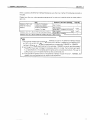

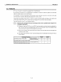
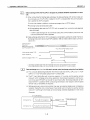


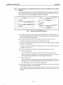

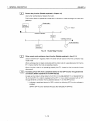
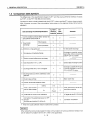
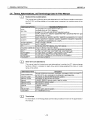
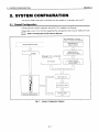

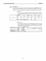

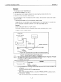

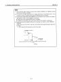


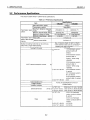


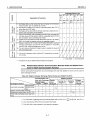


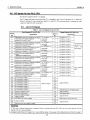
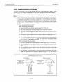


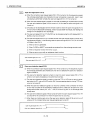

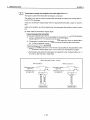
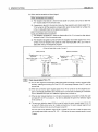
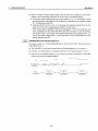
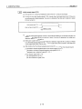

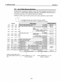
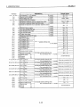


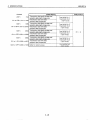


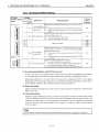


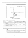

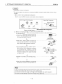


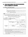
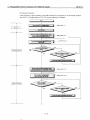
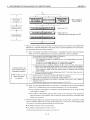
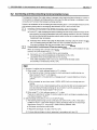
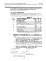
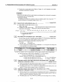
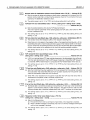
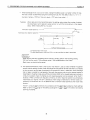

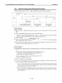


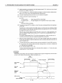

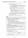

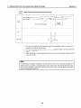


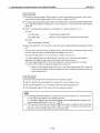

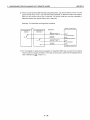

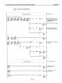
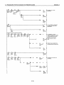
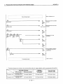

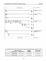
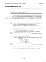
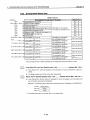
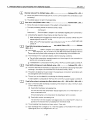
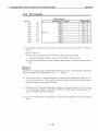
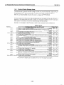

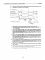
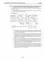
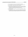
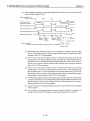

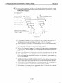

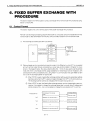

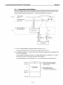
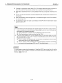
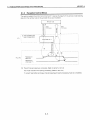
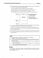
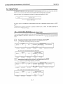
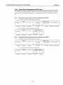
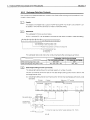


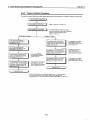


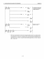

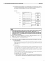


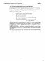
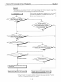

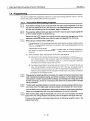
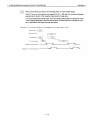
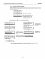
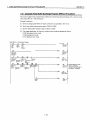


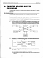
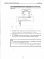
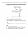


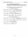
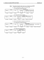
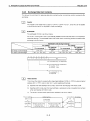
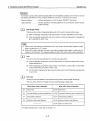


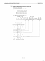
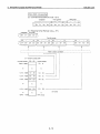
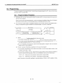
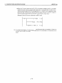
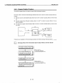
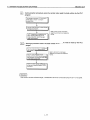


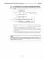
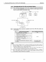
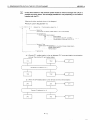
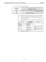

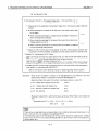
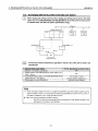
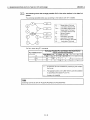


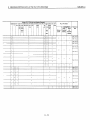


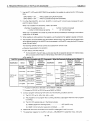
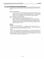
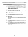

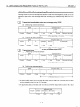
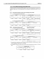

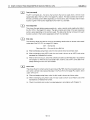
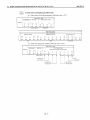
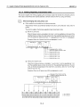


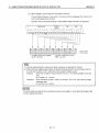
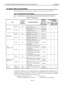
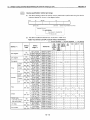

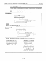
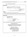

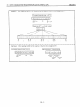

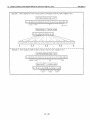


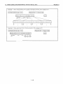


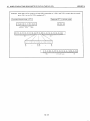
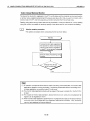


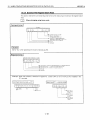
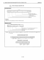

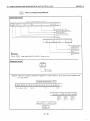


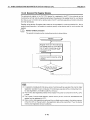


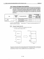
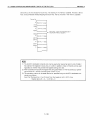


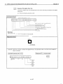
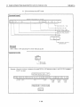
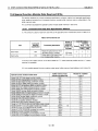
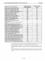

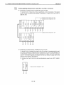
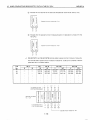
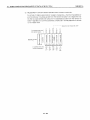
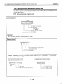
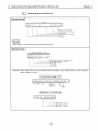


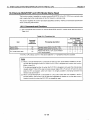
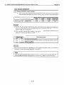

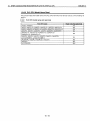

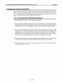


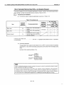
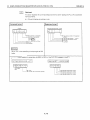
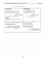


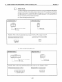
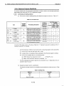
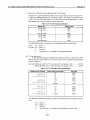
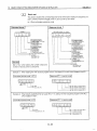
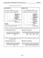
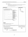


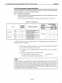


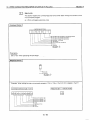
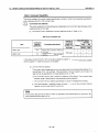
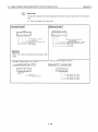
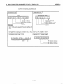
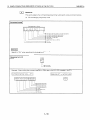

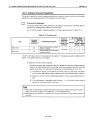

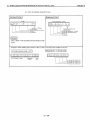


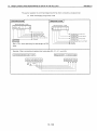


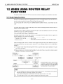


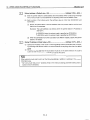


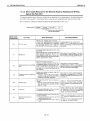


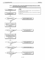

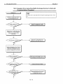
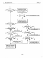
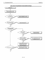
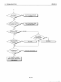

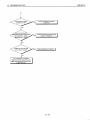
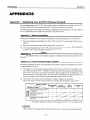
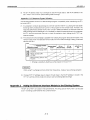


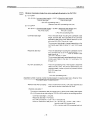

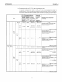
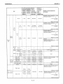


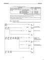
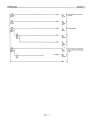

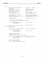
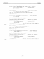
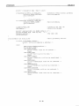

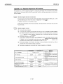
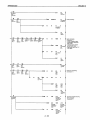
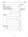

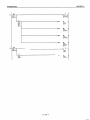
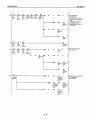
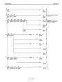
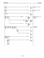
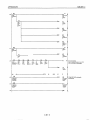


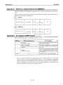


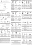
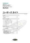
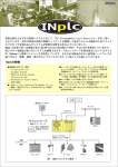


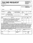

![BOS User`s Manual [v 1.00]](http://vs1.manualzilla.com/store/data/005878726_1-a93b95814f153b2994a972b38c1cdb16-150x150.png)