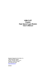
1
No Container-No Fill /
No Container-No Lid
Control System Manual
Revised: June 6, 2002
WARNING
To ensure that the equipment described by this Manual, as well as the
equipment connected to and used with it, operates satisfactorily and safely, all
applicable local and national codes that apply to installing and operating the
equipment must be followed. This includes the National Electrical Code in the
USA and other applicable legislation, regulations, and codes in practice
elsewhere. Since codes can vary geographically and can change with time, it is
the user’s responsibility to determine which standards and codes apply, and to
comply with them.
FAILURE TO COMPLY WITH APPLICABLE CODES AND STANDARDS CAN
RESULT IN DAMAGE TO EQUIPMENT AND/OR SERIOUS INJURY TO
PERSONNEL.
Persons supervising and performing installation or maintenance must be suitably
qualified and competent in these duties, and should carefully study the User
Manual and any other manuals referred to by it prior to installation and/or
operation of the equipment.
The manufacturer accepts no liability for any consequences resulting from
inappropriate, negligent or incorrect installation, operation, or adjustment of the
equipment.
The contents of the User Manual are believed to be correct at the time of
printing. However, no responsibility is assumed for inaccuracies. In the interests
of a commitment to a policy of continuous development and improvement, the
manufacturer reserves the right to change the specification of the product or its
performance or the contents of the User Manual without notice.
Table of Contents
1. INTRODUCTION .................................................................................................. 1
1.1 FEATURES ....................................................................................................... 1
1.2 FUNCTIONAL DESCRIPTIONS ...................................................................... 3
1.2.1 Lockout Actuator Control ............................................................................ 3
1.2.2 Pull-Out Cam Control.................................................................................. 3
1.2.3 Lid Feed Downstacker Actuator Control ...................................................... 3
1.2.4 Wash-Down Bypass Mode............................................................................ 4
2. INTERLOCKS WITH EXISTING CONTROL SYSTEM................................... 5
2.1 OUTGOING INTERLOCKS ............................................................................. 5
2.1.1 System Ready Interlock ................................................................................ 5
2.1.2 Alarm Interlock............................................................................................ 5
2.2 INCOMING INTERLOCKS .............................................................................. 6
2.2.1 Filler/Seamer Running................................................................................. 6
3. INSTALLATION.................................................................................................... 7
3.1 PACKING LIST................................................................................................. 7
3.2 POWER REQUIREMENTS .............................................................................. 7
3.3 INSTALLING THE NC-NF/NC-NL MODULE................................................. 8
3.4 WIRING TO THE NC-NF/NC-NL .................................................................. 10
3.4.1 Incoming Power......................................................................................... 10
3.4.2 Input Sensors ............................................................................................. 10
3.4.3 Setup Protection Input ............................................................................... 10
3.4.4 Close/Auto/Open Selector Switches (optional)............................................ 10
3.4.5 Outputs ...................................................................................................... 11
3.4.6 Interlocks Between Existing System and NC-NF/NC-NL............................. 11
3.5 POWER-UP SEQUENCE................................................................................ 12
3.6 MODIFY EXISTING PLC PROGRAM........................................................... 12
4. SETTING UP ........................................................................................................ 13
4.1 SETTING UP THE SENSORS ........................................................................ 14
4.1.1 Verify Filler Timing Sensor........................................................................ 15
4.1.2 Verify Filler Container Sensor ................................................................... 15
4.1.3 Verify Lockout Response Feedback Sensor................................................. 16
4.1.4 Verify Infeed Sensor (Optional).................................................................. 16
4.1.5 Verify Discharge Sensor (Optional) ........................................................... 16
4.1.6 Verify Seamer Timing Sensor ..................................................................... 16
4.1.7 Verify Seamer Container Sensor ................................................................ 17
4.2 SETTING UP THE SYSTEM PARAMETERS ............................................... 18
4.2.1 Navigating the Setup Menu ........................................................................ 18
4.2.2 Changing Setup Parameters....................................................................... 18
i
TABLE OF CONTENTS
4.3 PARAMETER DEFINITIONS ........................................................................ 18
4.3.1 Lockout Actuator Lead Times (Extend and Retract) ................................... 19
4.3.2 Maximum Lockout Response Time ............................................................. 19
4.3.3 Number of Stations Container Sensor to Lockout Actuator......................... 19
4.3.4 Automatic End Of Shift Timer .................................................................... 20
4.3.5 Consecutive Lockouts to Extend Pull-out Cam ........................................... 20
4.3.6 Enable Optional Sensors (Infeed and/or Discharge) .................................. 20
4.3.7 Number of Stations Infeed Sensor to Container Sensor ............................. 21
4.3.8 Number of Missing Containers to Constitute an Infeed Jam 1 ..................... 21
4.3.9 Infeed Low Timer 1 ..................................................................................... 21
4.3.10 Infeed Restart Timer 1 ................................................................................ 21
4.3.11 Number of Filler Stations Container Sensor to Discharge Sensor 2 ............ 22
4.3.12 Number of Seamer Stations Container Sensor to Discharge Sensor 2.......... 22
4.3.13 Number of Missing Containers to Constitute a Discharge Jam 2 ................ 22
4.3.14 Input Polarity............................................................................................. 22
4.3.15 Number of Stations Seamer Container Sensor to Lid Feed Actuator........... 23
4.3.16 Lid Feed Actuator Lead Times (Open and Close)....................................... 23
4.3.17 Lid Feed Solenoid(s) Pulse Duration ......................................................... 23
5. DISPLAYS ............................................................................................................ 24
5.1 ALARM MESSAGES...................................................................................... 24
5.1.1 Timing Sensor Failure ............................................................................... 24
5.1.2 Lockout Extend Too Slow........................................................................... 24
5.1.3 Lockout Retract Too Slow .......................................................................... 24
5.1.4 Container Detected In Wash-Down Bypass ................................................ 25
5.1.5 Infeed Jam ................................................................................................. 25
5.1.6 Infeed Low ................................................................................................. 25
5.1.7 Discharge Jam........................................................................................... 25
5.2 LOCKOUT RESPONSE LOOP ....................................................................... 26
5.3 PRODUCTION COUNT LOOP....................................................................... 26
5.4 RELATIVE TIMING DISPLAYS.................................................................... 27
5.5 OPERATOR KEYPAD REQUESTS ............................................................... 27
5.5.1 End of Shift................................................................................................ 27
5.5.2 Wash-Down Bypass Mode.......................................................................... 27
5.6 LOCKOUT ACTUATOR POSSIBLE PROBLEMS FEEDBACK.................... 28
5.6.1 Lockout Actuator Response Too Long for Speed Compensation ................. 28
5.6.2 Lockout Actuator Response Changing........................................................ 28
5.7 WASH-DOWN BYPASS MODE..................................................................... 28
5.8 CLOSE/AUTO/OPEN SWITCH SELECTION................................................ 29
5.9 MESSAGE LOGIC ERROR ............................................................................ 29
APPENDIX A -......................................................... KEYPAD QUICK REFERENCE
A1
APPENDIX B -..................................................M4502 APPEARANCE DRAWINGS
B1
APPENDIX C -................................................. CONTACTING COMPUTROL, INC.
C1
ii
TABLE OF CONTENTS
APPENDIX D -...................................................................................... SCHEMATICS
D1
APPENDIX E -.....................................................DF1 COMMUNICATION OPTION
E1
E.1 .............................................................................................................................E3
E.2 INTERPRETING N7 DATA ............................ EERROR! BOOKMARK NOT DEFINED.
E.2.1 Production Counts – (N7:0 – N7:11 / N7:50 – N7:61) ...............................E4
E.2.2 Message Number (N7:12) ..........................................................................E4
E.2.3 Lockout Actuator Response Times (Measured) (N7:15, N7:16) ................E10
E.2.4 Keypad Entry (N7:20)..............................................................................E11
E.2.5 Setup Values (N7:25 – N7:43)..................................................................E11
E.2.6 Manual Override Error Counts (N7:45 – N7:48 / N7:95-N7:98)..............E11
E.3 SAMPLE SLC 5/0X PROGRAMMING FOR INTERFACING WITH THE NC-NF/NC-NLE12
E.4 CHANNEL 0 SETUP ..........................................................................................E16
iii
Table of Figures
Figure 2-1 Alarm Output Table........................................................................................ 5
Figure 3-1: NEMA 12 Panel Cutout ................................................................................ 8
Figure 3-2: NEMA 4 Panel Cutout .................................................................................. 9
Figure 4-1 NC-NF / Filler Layout .................................................................................. 13
Figure 4-2 Input Sensor Timing Sequence ..................................................................... 14
Figure 4-3 Setup Parameters.......................................................................................... 18
Figure B-1: Top View of NC-NF/NC-NL Controller .....................................................B1
Figure B-2: Front View of NC-NF/NC-NL Controller ...................................................B1
Figure D-1: Schematic Sheet 1 ..................................................................................... D2
Figure D-2: Schematic Sheet 2 ..................................................................................... D3
Figure E-1: SLC (Replicated) Memory Addresses inside the NC-NF/NC-NL.................E2
iv
1. INTRODUCTION
This section describes the features of the NC-NF/NC-NL/NC-NL package, including the
functional description, alarms detected, and the interlocks between control package and
existing control system.
1.1 FEATURES
The NC-NF/NC-NL/NC-NL is designed to work in conjunction with the existing controls
for a food/beverage filling station connected directly to a Seamer. The system performs
the following functions:
1.
Speed compensated actuator control at speeds in excess of 2000 CPM (up to two
station advance) for both filler lockout (NC-NF) and Seamer downstacker (NCNL).
2.
Lockout Response Calibration: Automatic determination of lockout response for
use as extend and retract lead times.
3.
System Ready Interlock: dry contact interlock to indicate to the existing control
system that NC-NF/NC-NL system is ready for production.
1.
Module Fault protection: The NC-NF/NC-NL module contains a
comprehensive fault detection routine that verifies the proper operation of
the module at all times.
2.
Machine Run Enable Interlock: The summation of no active alarms.
4.
Data Acquisition: Total number of containers filled and total number of lockouts,
(for the current shift, the previous shift, and the lifetime of the system). Also, the
system tracks the number of times a station was filled without a container and the
number of containers not filled due to the manual override switch. Similar but
separate counts are kept for the Seamer as well.
5.
Built-in 2 Line X 40 character sealed display with 24 key membrane keypad
1.
Comprehensive status messages to aid in troubleshooting
2.
Local viewing of collected data
3.
Set-up parameters (viewed by operator, changed by authorized personnel)
4.
Alarm reset
5.
Local Wash-Down Bypass mode
6.
End of shift data transfer
1
SECTION 1
INTRODUCTION
6.
User Adjustable Parameters (protected):
1.
Lockout Actuator Extend Lead Time.
2.
Lockout Actuator Retract Lead Time.
3.
Maximum allowed Lockout response time.
4.
Number of stations Container Sensor to Lockout Actuator.
5.
Automatic End of Shift Timer.
6.
Number of consecutive Lockouts to extend Pull-out Cam.
7.
Enable Optional Sensors (Infeed and/or Discharge)**.
8.
* Number of stations Infeed sensor to Container sensor.
9.
* Number of missing containers to constitute an Infeed Jam.
10.
* Infeed Low Timer (0.1 second time base).
11.
* Infeed Restart Timer (0.1 second time base).
12.
* Number of stations Container sensor to Discharge sensor (Filler).
13.
* Number of stations Container sensor to Discharge sensor (Seamer).
14.
* Number of missing containers to constitute a Discharge Jam.
15.
Input Polarity
16.
Number of stations Container Sensor to Downstacker Actuator.
17.
Downstacker Actuator Close Lead Time.
18.
Downstacker Actuator Open Lead Time.
19.
Downstacker Actuator Solenoid Pulse Duration.
* Parameter only accessed if related sensor is enabled
** The discharge sensing for the filler and Seamer are enabled together. The Container
sensor for the Seamer is also used as a discharge sensor for the Filler.
7.
Alarm Detection
1.
Filler Timing Sensor Failure
2.
Seamer Timing Sensor Failure
3.
Lockout Extend Too Slow
4.
Lockout Retract Too Slow
5.
Container Detected in Wash-Down Bypass Mode
6.
Infeed Jam
7.
Infeed Low
8.
Filler Discharge Jam
9.
Seamer Discharge Jam
8.
The NC-NF/NC-NL package can be set up as a dedicated “black box” or as a fully
programmable PLC - implementing the high performance SYSTEMS M4502 PLC
that allows easy customization by Computrol or the end user. The M4502 module
is programmed using the DOS-based SYSdev programming package which allows
the module to be programmed in any combination of Ladder or high-level (subset
of “C”), as well as perform on-line monitoring, troubleshooting and module fault
diagnostics.
2
SECTION 1
INTRODUCTION
1.2
FUNCTIONAL DESCRIPTIONS
1.2.1 Lockout Actuator Control
The NC-NF/NC-NL provides direct control for the No Container-No Fill Lockout
Actuator Solenoid(s). The actuator is controlled by the Filler Container Sensor, working
in conjunction with the Filler Timing Sensor, such that when the Container Sensor does
detect a container somewhere between fill station timing signals, the Lockout Actuator
will not be activated. However, when the Container Sensor does not detect a container
between timing signals, the Lockout Actuator will be activated at a precise time to “hit”
the lockout pin to prevent an empty station from being filled. As soon as the Container
Sensor begins detecting containers again, the actuator will be retracted to prevent any
containers from not being filled.
The reaction of the Lockout Actuator is speed compensated. This means that as the speed
of the machine increases, (time period between fill stations decreases), the activation and
deactivation point of the actuator will be advanced to compensate for the speed of the
machine and the reaction time of the actuator. If the sensed reaction time of the Lockout
Actuator exceeds the user defined response time maximum, an alarm will be generated.
Optionally, the system can include a “No Fill”/“Auto”/“Fill” three-position switch,
allowing the operator to manually override the NC-NF controls. Statistics are kept for
Containers not filled and “no container” fills caused by the switch in manual override.
1.2.2 Pull-Out Cam Control
The NC-NF/NC-NL provides control for the Pull-out Cam Actuator Solenoid(s). When
the Pull-out Cam is retracted it resets the lockout pins for the next revolution. As long as
a normal flow of containers is detected, the Pull-out Cam will stay retracted. If there is a
predetermined (setup parameter) number of consecutive lockouts, the Pull-out Cam will
be extended to reduce wear and tear on both the Pull-out Cam and the Lockout Actuator.
Optionally, the system can include a “Extend”/“Auto”/“Retract” three-position switch,
allowing the operator to manually override the NC-NF controls.
1.2.3 Lid Feed Downstacker Actuator Control
The NC-NF/NC-NL provides direct control for the No Container-No Lid Downstacker
Actuator Solenoid(s). The actuator is controlled by the Seamer Container Sensor,
working in conjunction with the Seamer Timing Sensor, such that when the Container
Sensor does detect a container somewhere between Seamer timing signals, the Lid Feed
will be opened. However, when the Container Sensor does not detect a container
between timing signals, the Lid Feed will be closed at a precise time to prevent a lid from
feeding an empty station. As soon as the Container Sensor begins detecting containers
again, the lid feed will be opened to assure all containers receive a lid.
3
SECTION 1
INTRODUCTION
The reaction of the Lid Feed Downstacker Actuator is speed compensated. This means
that as the speed of the machine increases, (time period between seam stations decreases),
the activation and deactivation point of the actuator will be advanced to compensate for
the speed of the machine and the reaction time of the actuator.
Optionally, the system can include a “Close”/“Auto”/“Feed” three-position switch,
allowing the operator to manually override the NC-NL controls. Statistics are kept for
containers with no lid and lids with no container caused by the switch in manual override.
1.2.4 Wash-Down Bypass Mode
The NC-NF/NC-NL system provides for a Wash-Down Bypass condition. This can be
activated through the module keypad or by an optional remote switch. When the system
is in Wash-Down Bypass, the Lockout Actuator and Pull-out Cam are locked in the to-fill
position, Lid Feed is off, production and lockout counts are frozen and most alarms are
disabled. Because the Lockout Actuator is locked in position and fill counts are frozen,
the NC-NF/NC-NL system is not expecting to detect any containers throughout the
system. If the Container Sensor detects a container while the system is in Wash-Down
Bypass mode, an alarm is latched and the system enable interlock will be turned off.
4
2. INTERLOCKS WITH EXISTING CONTROL SYSTEM
The NC-NF/NC-NL system will need to exchange information with the existing filler
controls. These pieces of information are broken down into two categories: outgoing
(from NC-NF/NC-NL to Filler/Seamer) and incoming (from Filler/Seamer to NC-NF/NCNL).
2.1 OUTGOING INTERLOCKS
The following are signals from the NC-NF/NC-NL to the existing control system.
2.1.1 System Ready Interlock
This dry contact interlock indicates to the existing control system that the NC-NF/NC-NL
system is ready for production. The contact will close when the NC-NF/NC-NL system is
ready. It is recommended that if the System Ready interlock is off, the Filler/Seamer
should not run. The System Ready Interlock combines the following:
2.1.1.1 Module Fault Protection
The NC-NF/NC-NL module contains a comprehensive fault detection routine that verifies
the proper operation of the module at all times. The sources of these faults range from a
hardware failure of the module to an error in the loaded program. If a module fault is
detected, all outputs are disabled.
2.1.1.2 System Enable
The system enable provides a summary of all alarms detected by the NC-NF/NC-NL
software. When the System Enable signal is off, the Alarm Interlock should be referenced
for the cause.
2.1.2 Alarm Interlock
The alarms are available to the host PLC via discrete +24VDC outputs (15, 16 & 17).
These should be used to stop the machine and indicate the problem when any one of the
following alarms occurs. The outputs will follow the following pattern:
Figure 2-1 Alarm Output Table
Value
0
1
2
3
4
5
6
7
Output 17
0
0
0
0
1
1
1
1
Output 16
0
0
1
1
0
0
1
1
Output 15
0
1
0
1
0
1
0
1
Highest Priority Alarm Active
None (PLC Module Fault)
Filler or Seamer Timing Sensor Failure
Lockout Extend Too Slow
Lockout Retract Too Slow
Container in Wash-Down
Infeed Jam
Infeed Low
Filler or Seamer Discharge Jam
5
SECTION 2
INTERLOCKS
2.2 INCOMING INTERLOCKS
The following interlocks can be provided by the existing control system to the NCNF/NC-NL.
2.2.1 Filler/Seamer Running
This signal tells the NC-NF/NC-NL system when to look for the Timing Sensor signals.
6
3. INSTALLATION
This section gives instructions for installing the NC-NF/NC-NL system for the first time.
3.1 PACKING LIST
Verify that the following items are included when unpacking the NC-NF/NC-NL:
1ea.
1ea.
1ea.
NC-NF/NC-NL M4502 Module with required I/O.
NC-NF/NC-NL Control System Manual.
M4500 User’s Manual.
3.2 POWER REQUIREMENTS
NC-NF/NC-NL (M4502) Module
Voltage:
115/230 VAC
Current:
0.5/0.3 A
NC-NF/NC-NL I/O (Sensors, Output Solenoids, etc.)
Voltage:
24 VDC
Current:
Device dependent
Note that 24VDC solenoids must be used for the output solenoids. This is because DC
solenoids provide a more consistent, repeatable response than AC solenoids.
The input power should be interlocked with the existing control system such that when the
main disconnect of the existing control system is turned off, all power to the NC-NF/NCNL is also turned off.
7
SECTION 3
INSTALLATION
3.3 INSTALLING THE NC-NF/NC-NL MODULE
The NC-NF/NC-NL is designed to mount from the front in the user’s cabinet door. Use
the cutout in Figure 3-1 for NEMA 12. Use the cutout in Figure 3-2 for NEMA 4 (washdown area).
1) Remove all terminal connectors so that the module can easily slide into the
recommended cutout.
2) Referring to the appropriate figure (see above), put a cutout in the door of the
enclosure.
3) With the gasket installed on the M4502 mounting studs, slide the module into the
cutout from the front. Attach the M4502 to the door with the supplied hardware. Once
the module is installed, a lugged earth ground wire should be installed on one of the
mounting screws to insure that the module is grounded.
4) In the case of NEMA 4 mounting, place the bezel over the front of the display. Be
careful that the gasket forms a good seal with the front of the display. Attach with the
supplied hardware.
4) Replace all terminal connectors on the module to begin terminating wires.
4.475
4.475
0.250
8.000
3.500
4.938
1.875
0.475
1.775
4.450
Ø0.218
Figure 3-1: NEMA 12 Panel Cutout
8
SECTION 3
INSTALLATION
Figure 3-2: NEMA 4 Panel Cutout
9
SECTION 3
INSTALLATION
3.4 WIRING TO THE NC-NF/NC-NL
Referring to the electrical control schematic in Appendix D, wire the NC-NF/NC-NL as
follows:
3.4.1 Incoming Power
Be sure all power is disconnected before wiring the system. In general, when wiring the
NC-NF/NC-NL, keep all +24VDC wiring away from high voltage wiring.
1. 110 - 240VAC 50/60HZ power to the M4502 NC-NF/NC-NL module.
2. +24VDC power to the S4568 I/O boards and M4502 (for use with the input IN0).
3.4.2 Input Sensors
Connect +24VDC power to all input sensors. Note that pull-up resistors (4.7kΩ) may be
required to provide a minimum load for sensors using NPN outputs. Check the
specifications for the sensor model used. If no information on minimum load is available,
install the pull-up resistor.
1.
2.
3.
4.
5.
6.
7.
Filler Container Sensor (PRX1).
Filler Timing Sensor (PRX2).
Infeed Sensor (PRX3) (optional).
Seamer Discharge Sensor (PRX4) (optional).
Lockout Response Feedback Sensor (PRX5).
Seamer Container Sensor (PRX6). (option to use as Filler Discharge also)
Seamer Timing Sensor (PRX7).
3.4.3 Setup Protection Input
Enable Setup Changes switch. A switch inside the panel is recommended to prevent
unauthorized access.
3.4.4 Close/Auto/Open Selector Switches (optional)
These switches allow a manual override of the NC-NF/NC-NL, allowing the Lockout
Actuator, Pull-out Cam and Lid Feed to be forced open (to-fill) or closed (no fill).
10
SECTION 3
INSTALLATION
3.4.5 Outputs
Note that 24VDC coils must be used for all outputs.
1. Wire CR1 Relay into NC-NF/NC-NL FLT Output (Note polarity of coil).
2. Wire CR1 Relay into Slot 0 Output 2 (Note polarity of coil).
3. Wire Fill Lockout Solenoid(s).
4. Wire Pull-out Cam Solenoid(s) (optional).
5. Wire Lid Feed Solenoid(s).
3.4.6 Interlocks Between Existing System and NC-NF/NC-NL
1. System Ready (dry contact) interlock to inputs on existing PLC.
2. Alarm Binary Code outputs to inputs on existing PLC.
3. Auxiliary contact from main drive to NC-NF/NC-NL.
4. Optional E-Stop or machine control system MCR contact.
11
SECTION 3
INSTALLATION
3.5 POWER-UP SEQUENCE
Once the connectors are wired and replaced in their respective sockets, apply
115/230VAC power to the M4502. The Power-Up sequence occurs as follows:
1. At initial power-up, the module is reset for approximately half a second. During this
time, the fault interlock will be “off”, and the “FLT”, “RUN” and “PWR” LED’s will
all be “on”. All outputs will be “off”.
2. Once the reset cycle is complete, the module will begin to execute the NC-NF/NC-NL
application program. The fault interlock will turn “on” (sink true low) and the “FLT”
LED will turn off.
3. If the red “FLT” LED stays on after the power-up is complete, read the fault code in
the M4502 module, (see section 6.2 of the M4500 User’s Manual for information on
viewing fault codes with SYSdev.)
3.6 MODIFY EXISTING PLC PROGRAM
Modify the existing control system PLC program to interface with the NC-NF/NC-NL by
incorporating the following into the existing PLC logic:
1. Add the “System Ready” output from the NC-NF/NC-NL as an input into the existing
control system to immediately disable the main drive upon loss of signal. This can also
be used as a “Summary Alarm” input.
2. Add the necessary logic to process the Alarm Binary Code outputs from the NCNF/NC-NL.
3. Optionally, add the software necessary to use DF1 to communicate to the NC-NF/NCNL. Refer to Appendix E.
12
4. SETTING UP
Setting up the NC-NF/NC-NL system involves two steps: setting up the sensors and
setting up the system parameters.
Figure 4-1 NC-NF / Filler Layout
13
SECTION 4
SETTING UP
4.1
SETTING UP THE SENSORS
TIMING
SENSOR
1
0
CONTAINER 1
SENSOR
INFEED
SENSOR
0
1
0
DISCHARGE 1
SENSOR
0
ALL CONTAINER SENSORS MUST READ ONCE PER TIMING SENSOR SIGNAL
Figure -2 Input Sensor Timing Sequence
14
SECTION 4
SETTING UP
4.1.1 Verify Filler Timing Sensor
4.1.1.1 Signal Expected
With the machine running, the Timing Sensor should pulse once and only once for every
fill station.
4.1.1.2 Placement of Sensor
The Timing Sensor must turn “on” at the position the Lockout Actuator is to be tripped.
This sensor can be placed anywhere on the periphery of the machine that will pick up the
timing signal.
4.1.2 Verify Filler Container Sensor
4.1.2.1 Signal Expected
The Container Sensor should turn “on” only when a container is present at its location,
resulting in a single pulse per container.
4.1.2.2 Placement of Sensor
Count the number of stations between the Lockout Actuator to the point where containers
are transferred to the filler turret. The Container Sensor should be located at least 3 (no
more than 15) stations further from the transfer point than the Lockout Actuator.
Press the “T-C-T” key to bring up the Relative Timing display. Note that pressing “Prev”
or “Next” will toggle between Filler and Seamer displays.
FILLER CONTAINER RELATIVE TIMING = ##%
T - C - T
T
T
Using the Relative Timing display, verify that the container sensor signal stays between the
same two stations for the full speed range of the setup. This means that the relative timing
number should not cross the 0/100 % threshold.
15
SECTION 4
SETTING UP
4.1.3 Verify Lockout Response Feedback Sensor
4.1.3.1 Signal Expected
With the Lockout Actuator fully retracted, the Lockout Response Feedback Sensor should
be “on”. Once the Actuator begins to extend, the sensor should turn “off”.
4.1.3.2 Placement of Sensor
Sensor should be placed on the Lockout Actuator in a way to give the signal expected.
4.1.4 Verify Infeed Sensor (Optional)
4.1.4.1 Signal Expected
The Infeed Sensor should turn “on” only when a container is present at its location,
resulting in a single pulse per container.
4.1.4.2 Placement of Sensor
The infeed sensor should be located at the end of the infeed track, very near to where the
containers are first loaded into the machine.
4.1.4.3 If the Pull-out Cam is controlled
Count the number of stations between the Pull-out Cam to the point where containers are
transferred to the filler turret. The Infeed Sensor should be located at least 3 stations
further from the transfer point than the Pull-out Cam. The Infeed Sensor should not be
located more than 45 stations from the Container Sensor.
4.1.5 Verify Discharge Sensor (Optional)
4.1.5.1 Signal Expected
The Infeed Sensor should turn “on” only when a container is present at its location,
resulting in a single pulse per container.
4.1.5.2 Placement of Sensor
Verify that the discharge sensor is located on the discharge track where the filled
containers are discharged from the machine.
4.1.6 Verify Seamer Timing Sensor
4.1.6.1 Signal Expected
With the machine running, the Timing Sensor should pulse once and only once for every
Seamer station.
4.1.6.2 Placement of Sensor
The Timing Sensor must turn “on” at the position the Lid Feed Actuator is to be tripped.
This sensor can be placed anywhere on the periphery of the machine that will pick up the
timing signal.
16
SECTION 4
SETTING UP
4.1.7 Verify Seamer Container Sensor
4.1.7.1 Signal Expected
The Container Sensor should turn “on” only when a container is present at its location,
resulting in a single pulse per container.
4.1.7.2 Placement of Sensor
Count the number of stations between the Lid Feed Actuator to the point where
containers are transferred to the Seamer turret. The Container Sensor should be located at
least 3 (no more than 15) stations further from the transfer point than the Lid Feed
Actuator.
Press the “T-C-T” key to bring up the Relative Timing display. Note that pressing “Prev”
or “Next” will toggle between Filler and Seamer displays.
SEAMER CONTAINER RELATIVE TIMING = ##%
T - C - T
T
T
Using the Relative Timing display, verify that the container sensor signal stays between the
same two stations for the full speed range of the setup. This means that the relative timing
number should not cross the 0/100 % threshold.
17
SECTION 4
SETTING UP
4.2
SETTING UP THE SYSTEM PARAMETERS
4.2.1 Navigating the Setup Menu
The Setup parameters for the NC-NF/NC-NL may be viewed at all times by pressing the
“SETUP” key. When Setup Mode is accessed, the display for the last parameter viewed
will be recalled. The “PREV” and “NEXT” keys move to the Previous and Next
parameters respectively.
4.2.2 Changing Setup Parameters
In order to change the parameter values, the Enable Setup Changes input at IN0 must be
on. If changes are attempted and IN0 is off, the following will be displayed:
CHANGES IN SETUP ARE NOT ENABLED
CHECK MANUAL FOR SETUP PROCEDURE
If Changes are enabled, the values can be changed using the “INC” and “DEC” keys.
4.3
PARAMETER DEFINITIONS
Figure 4-3 Setup Parameters
P#
1
2
3
4
5
6
7
8
9
10
11
12
13
14
15
16
17
18
19
Parameter
Lockout Solenoid Lead Time (Extend)
Lockout Solenoid Lead Time (Retract)
Lockout Solenoid Response Time (Max)
Stations from Container Prx to Lockout
Auto Shift Timer
Lockouts to Extend Pull-out Cam
Enable Optional Sensors
Stations from Infeed to Container
Missing Containers for Infeed Jam
Infeed Low Shutdown
Infeed OK to Restart
Fill Stations from Container to Discharge
Seam Stations Container to Discharge
Missing Containers for Discharge Jam
Input Polarity
Seam Stations from Container to Lid Feed
Lid Feed Solenoid Lead Time (Close)
Lid Feed Solenoid Lead Time (Open)
Lid Feed Solenoid Pulse duration
Default
45
45
150
3
43200
25
0
5
2
5.0
5.0
25
25
2
255
3
1
1
1
Min.
1
1
15
3
1
1
0
1
1
0.1
0.1
5
5
1
0
3
45
45
45
Max.
150
150
250
15
64800
99
3
45
9
600.0
60.0
99
45
9
255
15
150
150
150
Units
ms
ms
ms
stations
seconds
stations
N/A
stations
containers
seconds
seconds
stations
stations
containers
N/A
Stations
ms
ms
ms
18
SECTION 4
SETTING UP
4.3.1 Lockout Actuator Lead Times (Extend and Retract)
NC-NF/NC-NL SYSTEM IN SETUP MODE
1: LOCKOUT EXTEND LEAD TIME: ### MS
NC-NF/NC-NL SYSTEM IN SETUP MODE
2: LOCKOUT RETRACT LEAD TIME: ### MS
point. To access the Lockout Response Feedback displays, press the “L/O SOL TIMES”
key. “PREV” or “NEXT” will toggle between Extend and Retract. Note that the
accurate. Use the Close/Auto/Open Switch. The default readouts are 45ms each way.
If the Lockout Actuator does not extend early enough to “hit” the lockout pin, increase
the next loaded station, increase the Retract Lead Time.
Note: if the measured time for either extend or retract is more than 20 milliseconds
message is intended to alert the operator to changes in the response time of the actuator
so that corrective action can be taken.
Maximum Lockout Response Time
3: LOCKOUT MAX RESPONSE TIME: ### MS
The measured response times for extend and retract will be checked against this limit to
personnel know that there are mechanical response problems in the Lockout Actuator.
4.3.3 Number of Stations Container Sensor to Lockout Actuator
NC-NF/NC-NL SYSTEM IN SETUP MODE
Count the number of stations between the Lockout Actuator to the point where containers
are transferred to the filler turret. Now count the number of stations between the
those two numbers. If the Lockout Actuator is consistently hitting a complete station
before or after the intended station, change this parameter.
19
SECTION 4
SETTING UP
4.3.4 Automatic End Of Shift Timer
NC-NF/NC-NL SYSTEM IN SETUP MODE
5: AUTO SHIFT TIMER: ## H ## M ## S
counts are maintained for the current shift, the previous shift and the lifetime of the
system. In order to protect the integrity of the shift counters, the shift times must be
can also be rolled over using the keypad. If the shift counts are updated by either of these
means, the Auto Shift Timer will reset.
Consecutive Lockouts to Extend Pull-out Cam
6: LOCKOUTS TO EXTEND PULL-OUT CAM: ##
The Pull-out Cam resets the lockout pins for the next revolution of the filler. If a
to reduce wear and tear on the Lockout Actuator and the Cam itself. The Cam will be
retracted upon the first container detected. Enter the number of consecutive missing
4.3.6
NC-NF/NC-NL SYSTEM IN SETUP MODE
7:SENSOR ENABLE: # (1=IN,2=EXIT,3=BOTH)
Sensors. In order to avoid nuisance alarms if these sensors are not installed, the installed
sensors must be enabled for the related logic to be processed. To enable the logic related
Discharge Sensor only, set this parameter to “2”. To enable both sensors, set this
parameter to “3”. If either of the sensors is disabled, the related parameters will be
20
SECTION 4
SETTING UP
4.3.7 Number of Stations Infeed Sensor to Container Sensor 1
NC-NF/NC-NL SYSTEM IN SETUP MODE
8: STATIONS FROM INFD TO CONT: ##
Enter the number of stations between the Infeed and Container Sensors. This information
is used for detecting Infeed Jams.
4.3.8 Number of Missing Containers to Constitute an Infeed Jam 1
NC-NF/NC-NL SYSTEM IN SETUP MODE
9: CONTAINERS MISSING FOR INFEED JAM: #
Enter the number of containers lost between the Infeed Sensor and the Container Sensor
before an Infeed Jam alarm is latched.
4.3.9 Infeed Low Timer 1
NC-NF/NC-NL SYSTEM IN SETUP MODE
10: INFEED LOW TIME: ###.# SECONDS
If no containers are detected at the Infeed Sensor for this long, the Infeed Low alarm will
be latched, to shut the filler down.
4.3.10 Infeed Restart Timer 1
NC-NF/NC-NL SYSTEM IN SETUP MODE
11: INFEED RESTART TIME: ##.# SECONDS
Containers will be detected at the Infeed Sensor for this long before the Infeed Low alarm
will automatically reset to allow the filler to run.
1
These parameters will only appear if Infeed Sensor is enabled in Parameter 7 (Parameter 7 = 1 or 3).
21
SECTION 4
SETTING UP
4.3.11 Number of Filler Stations Container Sensor to Discharge Sensor 2
NC-NF/NC-NL SYSTEM IN SETUP MODE
12: FILL STATIONS FROM CONT TO EXIT: ##
Count the number of stations between the Filler Container Sensor and the Seamer
Container Sensor. This information is used to detect a Discharge Jam alarm.
4.3.12 Number of Seamer Stations Container Sensor to Discharge Sensor 2
NC-NF/NC-NL SYSTEM IN SETUP MODE
13: SEAM STATIONS FROM CONT TO EXIT: ##
Count the number of stations between the Seamer Container Sensor and the Discharge
Sensor. This information is used to detect a Discharge Jam alarm.
4.3.13 Number of Missing Containers to Constitute a Discharge Jam 2
NC-NF/NC-NL SYSTEM IN SETUP MODE
14: CONTAINERS MISSING FOR EXIT JAM: #
Enter the number of containers lost between the Container Sensor and the Discharge
Sensor before a Discharge Jam alarm is latched.
4.3.14 Input Polarity
NC-NF/NC-NL SYSTEM IN SETUP MODE
15: INPUT POLARITY TCAFDITC: ########
The NC-NF/NC-NL software is designed to handle PNP (24VDC = “1”) or NPN (0VDC
= “1”) inputs. The input polarity can be changed for all 7 sensors, plus the auxiliary
contact from the Main Drive. The Push-button and Selector Switch inputs are assumed
PNP. The legend is given as a reminder of the schematic: (C = (Filler) Container Sensor,
T= (Filler) Timing Sensor, I = Infeed Sensor, D = Discharge Sensor, F = Feedback
Response Sensor, A = Auxiliary Contact from Main Drive, C = (Seamer) Container
Sensor, T= (Seamer) Timing Sensor). A “1” in the Polarity Summary designates PNP,
while a “0” designates NPN.
2
These parameters will only appear if Discharge Sensors are enabled in Parameter 7 (Parameter 7 = 2 or
3).
22
SECTION 4
SETTING UP
4.3.15 Number of Stations Seamer Container Sensor to Lid Feed Actuator
NC-NF/NC-NL SYSTEM IN SETUP MODE
16: SEAM STATIONS CONT TO LID FEED: ##
Count the number of stations between the Lid Feed Actuator to the point where
containers are transferred to the Seamer turret. Now count the number of stations between
the Container Sensor and the transfer point. This parameter should be set to the
difference of those two numbers. If the Lid Feed is consistently hitting a complete station
before or after the intended station, change this parameter.
4.3.16 Lid Feed Actuator Lead Times (Open and Close)
NC-NF/NC-NL SYSTEM IN SETUP MODE
17: LID FEED CLOSE LEAD TIME: ### MS
NC-NF/NC-NL SYSTEM IN SETUP MODE
18: LID FEED OPEN LEAD TIME: ### MS
The default readouts are 45ms each way.
If the Lid Feed does close early enough to stop the feed for the intended station, increase
the Close Lead Time. Likewise, if the Lid Feed does not open early enough to feed the
next loaded station, increase the Open Lead Time.
4.3.17 Lid Feed Solenoid(s) Pulse Duration
NC-NF/NC-NL SYSTEM IN SETUP MODE
19: LID FEED SOLENOID(S) ON TIME:### MS
This is the duration of the pulse sent to the solenoid(s) that actuate the lid feed
downstacker. Pulsing the output(s) allows for the possibility of overdriving the coil(s).
23
5. DISPLAYS
5.1 ALARM MESSAGES
The NC-NF/NC-NL package detects the following alarms: Timing Sensor Failure,
Lockout Extend Too Slow, Lockout Retract Too Slow, Container Detected in WashDown Bypass, Infeed Jam, Infeed Low, and Discharge Jam. If any alarm is detected, the
system enable is turned off, and the drive to the machine should be disengaged. With no
alarms detected, the system enable will be on and the drive to the machine should be
enabled. The highest priority active alarm will be written to the display.
5.1.1 Timing Sensor Failure
FILLER TIMING SIGNAL FAILURE
CHECK SENSOR PRX2 AND RESET
SEAMER TIMING SIGNAL FAILURE
CHECK SENSOR PRX7 AND RESET
The timing sensor is used to determine the period between stations and the speed of the
machine. The time period between stations is tracked. If, after 3.0 seconds of the “drive
running” interlock on, the current period between stations is 1.5 times greater than the
previous time period, this alarm is latched. If this alarm is detected, make sure that the
Timing Sensor senses every station. If the “drive running” interlock is not used, the check
for this alarm will not be performed.
5.1.2 Lockout Extend Too Slow
LOCKOUT EXTEND RESPONSE TOO SLOW- CHECK
PRX5 AND MAX TIME SETTING - PRESS RESET
This alarm is generated whenever the measured Extend Response time of the Lockout
Actuator is greater than the setup parameter “Maximum Allowable Lockout Response”.
5.1.3 Lockout Retract Too Slow
LOCKOUT RETRACT RESPONSE TOO SLOW-CHECK
PRX5 AND MAX TIME SETTING - PRESS RESET
This alarm is generated whenever the measured Retract Response time of the Lockout
Actuator is greater than the setup parameter “Maximum Allowable Lockout Response”.
24
SECTION 5
DISPLAYS
5.1.4 Container Detected In Wash-Down Bypass
WASH-DOWN BYPASS FAILURE- CONTAINER WAS
SEEN AT PRX1 IN WASH-DOWN - PRESS RESET
When the NC-NF/NC-NL system is in Wash-Down Bypass Mode, production and lockout
counts are bypassed. To maintain the integrity of these statistics, no containers should pass
through the system while it is in this mode.
5.1.5 Infeed Jam
INFEED JAM - CONTAINER SEEN AT INFD BUT
NOT AT CONT- CHECK INFEED SCREW & RESET
The Infeed Sensor and the Container Sensor are placed in the infeed track to verify that
containers are being fed into the machine. If containers are detected at the Infeed Sensor
and are not detected by the Container Sensor (several stations later), the container is
considered missing. After a user defined number of missing containers (setup parameter),
an Infeed Jam is detected. If the Infeed Sensor is not enabled, this alarm is bypassed.
5.1.6 Infeed Low
NO CONTAINERS DETECTED AT INFD - CHECK
INFD & CONTAINER FLOW - PRESS RESET
The Infeed Sensor is used to verify that there are containers to be loaded into the machine
from the infeed track. If no containers are detected at the Infeed Sensor for a predefined
period of time (setup parameter), the infeed low alarm will become true. The alarm will
reset after containers have been continuously detected at the Infeed Sensor for a (setup
parameter) period of time. This alarm is overridden in Wash-Down Bypass Mode. If the
Infeed Sensor is not enabled, this alarm is bypassed.
5.1.7 Discharge Jam
FILLER EXIT JAM- CONTAINER SEEN AT CONT
BUT NOT AT EXIT-CHECK EXIT AREA & RESET
SEAMER EXIT JAM- CONTAINER SEEN AT CONT
BUT NOT AT EXIT-CHECK EXIT AREA & RESET
As containers are being fed into the machine, the container sensor determines the state of
the fill station, (container or no container). The state of the fill station is tracked to the
discharge of the machine. If filled containers are expected and the Discharge Sensor does
not detect them, those containers are considered missing. After a user defined number of
missing containers (setup parameter), a Discharge Jam is detected. If the Discharge
Sensor is not enabled, this alarm is bypassed.
25
SECTION 5
DISPLAYS
5.2 LOCKOUT RESPONSE LOOP
As long as no alarms are active, the operator can view the Extend and Retract times
measured by pressing the “L/O SOL TIMES” key. “PREV” and “NEXT” will toggle
between the two displays. The display will reset after 30 seconds of no keys being pressed.
LOCKOUT MECHANISM RESPONSE AS MEASURED
LOCKOUT EXTEND RESPONSE: ### MS
LOCKOUT MECHANISM RESPONSE AS MEASURED
LOCKOUT RETRACT RESPONSE: ### MS
5.3 PRODUCTION COUNT LOOP
If system is in Wash-Down Mode or sitting on the Default Current Shift Display, the
operator can view all 8 of the Production Count Displays by pressing “PREV” or
“NEXT”. These same keys will page through these displays. The display will reset after
30 seconds of no keys being pressed.
SYSTEM NO CONTAINER FILLS: ###,###,###
LIFE CONTAINERS NOT FILLED: ###,###,###
PREVIOUS SHIFT
FILLS: #,###,###
LOCKOUTS: #,###,###
FILLER SPEED: #### CPM
FILLS: #,###,###
LOCKOUTS: #,###,###
SYSTEM LIFE FILLS: ###,###,###
LOCKOUTS: ###,###,###
SYSTEM
LIFE
NO CONTAINER LIDS: ###,###,###
CONTAINERS NO LID: ###,###,###
PREVIOUS SHIFT
LIDS: #,###,###
NO LIDS: #,###,###
FILLER SPEED: #### CPM
LIDS: #,###,###
NO LIDS: #,###,###
SYSTEM LIFE LIDS: ###,###,###
NO LIDS: ###,###,###
26
SECTION 5
DISPLAYS
5.4 RELATIVE TIMING DISPLAYS
If none of the other feedback displays are active, the operator can view the relative timing
of the Container and Timing Sensors by pressing the “T-C-T” key. This display will stay
active until “T-C-T” or “Alarm Reset” is pressed (no 30-second timeout). The “Prev” and
“Next” keys will toggle between Filler and Seamer.
FILLER CONTAINER RELATIVE TIMING = ##%
T - C - T
T
T
SEAMER CONTAINER RELATIVE TIMING = ##%
T - C - T
T
T
The percentage represents the ratio of the time between the Timing Sensor and the
Container Sensor over the period between Timing Sensor pulses. Minimum value is 0% (if
both signals are detected at the same time). Maximum value is 99% (if the Container
Sensor is detected immediately before the next Timing Sensor pulse).
5.5
OPERATOR KEYPAD REQUESTS
5.5.1 End of Shift
The operator can manually transfer and reset the current shift data using the “End of Shift”
key on the keypad. When the “End of Shift” key is pressed, a confirmation is requested:
END OF SHIFT REQUESTED
ARE YOU SURE? (YES/NO)
Pressing the “Yes” key will transfer and reset the data. Pressing the “No” key will cancel
the request.
5.5.2 Wash-Down Bypass Mode
The operator can manually enter Wash-Down Bypass mode using the “Wash-Down” key
on the keypad. When the “Wash-Down” key is pressed, a confirmation is requested:
WASH-DOWN BYPASS REQUESTED
ARE YOU SURE? (YES/NO)
Pressing the “Yes” key will put the system in Wash-Down Bypass mode. Pressing the
“No” key will cancel the request.
27
SECTION 5
DISPLAYS
5.6
LOCKOUT ACTUATOR POSSIBLE PROBLEMS FEEDBACK
5.6.1 Lockout Actuator Response Too Long for Speed Compensation
If the measured response of the Lockout Actuator is longer than the period for two
stations, the speed compensation function cannot operate properly. When this is first
detected, a display will be triggered to notify the operator. If “Alarm Reset” is pressed,
this message will not return until the condition goes away and returns.
LOCKOUT SOLENOID RESPONSE > 2 STATIONS
PRESS 'RESET' TO ACKNOWLEDGE
5.6.2 Lockout Actuator Response Changing
If the measured response of the Lockout Actuator is more than 20ms different from the
setup value being used, a display will be triggered to notify the operator. This is intended
to notify the operator in changes in lockout actuation time - indicating faulty operation of
the actuator itself. If “Alarm Reset” is pressed, this message will not return until the
condition goes away and returns.
L/O RESPONSE MEASURED <> SETUP VALUE
(CHECK SETUP VALUE) RESET TO ACKNOWLEDGE
5.7 WASH-DOWN BYPASS MODE
If the system is in Wash-Down Bypass Mode, and none of the feedback messages are
active, the display will indicate the trigger for Wash-Down Bypass Mode.
SYSTEM IN WASH-DOWN BYPASS BY KEYPAD
PRESS 'RESET' OR 'WASH-DOWN' TO CANCEL
SYSTEM IN WASH-DOWN BYPASS BY REM SWITCH
28
SECTION 5
DISPLAYS
5.8 CLOSE/AUTO/OPEN SWITCH SELECTION
If any Lockout/Pullout/Lid Feed Switch is not in Auto, the display will say so.
LOCKOUT SWITCH IN FILL
PRESS 'WASH-DOWN' IF CLEANING THE FILLER
LOCKOUT SWITCH IN NO FILL
PULLOUT CAM SWITCH IN RETRACT (MAY FILL)
PULLOUT CAM SWITCH IN EXTEND(NEVER FILL)
LID FEED SWITCH IN FEED (ALWAYS FEED)
LID FEED SWITCH IN CLOSE (NEVER FEED)
5.9 MESSAGE LOGIC ERROR
If the program, after a revision, contains an error in the message logic where a message is
called for but not found, a display is provided for troubleshooting the problem.
MESSAGE LOGIC ERROR - MESSAGE NOT FOUND
NO MESSAGE ENTERED FOR B152 = ###
29
Appendix A - Keypad Quick Reference
Resets all displays and acknowledged alarms.
Triggers the Lockout Actuator Response Display Loop.
Activates the Relative Timing display.
Transfers the Current Shift Production data to Previous Shift and resets the
Current Shift. Must be confirmed.
Puts the NC-NF/NC-NL in Wash-Down Bypass Mode. Must be confirmed.
Confirms “End of Shift” or “Wash Down” requests.
Declines “End of Shift” or “Wash Down” requests.
Activates the Setup Mode display loop.
Moves display to next message in current display loop.
Moves display to previous message in current display loop.
Increases the value of the Setup Parameter (if changes are enabled).
Decreases the value of the Setup Parameter (if changes are enabled).
Acknowledges the currently shown alarm.
A1
Appendix B - M4502 Appearance Drawings
Figure B-1: Top View of NC-NF/NC-NL Controller
Figure B-2: Front View of NC-NF/NC-NL Controller
B1
Appendix C - Contacting Computrol, Inc.
We at Computrol are committed to providing excellent technical support for our control
systems. We are also interested in any comments or suggestions you may have toward
improving these systems. If you need troubleshooting help, or just have a suggestion for
an improvement, please feel free to contact us.
Computrol, Inc.
15485 W. 44th Ave. Unit A
Golden, CO 80403
Phone: (303) 989-4417
Toll Free: (800) 989-4417
Fax: (303) 989-4471
E-mail: [email protected]
C1
Appendix D - Schematics
The schematic for this system is included for quick reference.
D1
COMPUTROL, INC.
APPENDIX D
Schematic
Figure D-1: Schematic Sheet 1
D2
COMPUTROL, INC.
APPENDIX D
Schematic
Figure D-2: Schematic Sheet 2
D3
Appendix E - DF1 Communication Option
The NC-NF/NC-NL has the capability of communicating via Allen-Bradley DF1 Full
Duplex protocol. The S4516-DF1 board must be added to the rack (default slot 02).
With this optional card in place, the NC-NF/NC-NL can communicate directly with an AB PLC (via Channel 0 RS232C). A KF2 (or equivalent) card could also be used to
connect the NC-NF/NC-NL directly to an A-B Data Highway Plus network. Refer to page
2 of the NC-NF/NC-NL schematic for connection details.
The NC-NF/NC-NL will respond to MSG Block Read and Write commands intended for
a SLC500 PLC. An example program has been enclosed with this manual and is shown in
section E.2. The data is stored in accordance with Figure E-1.
E1
APPENDIX E
DF1 Communication
Figure E-1: SLC (Replicated) Memory Addresses inside the NC-NF/NC-NL
N7:
0
1
2
3
4
5
6
7
8
9
10
11
12
13,14
15
16
17-19
20
21-24
25
26
27
28
29
30
31
32
33
34
35
36
37
38
39
40
41
42
43
44
45
46
Used For / Represents
Filler Previous Shift Production Count Low Word
Filler Previous Shift Production Count High Word
Filler Previous Shift Lockout Count Low Word
Filler Previous Shift Lockout Count High Word
Filler Current Shift Production Count Low Word
Filler Current Shift Production Count High Word
Filler Current Shift Lockout Count Low Word
Filler Current Shift Lockout Count High Word
Filler System Life Production Count Low Word
Filler System Life Production Count High Word
Filler System Life Lockout Count Low Word
Filler System Life Lockout Count High Word
Message Number
Not Used
Lockout Actuator Extend Time Measured
Lockout Actuator Retract Time Measured
Not Used
Keypad Entry
Not Used
Lockout Actuator Extend Lead Time
Lockout Actuator Retract Lead Time
Maximum Lockout Solenoid Response Time
Number of Stations from Container Sensor to Lockout Actuator
Auto Shift Timer
Number of Lockouts to Extend Pull-out Cam
Enable Optional Sensors
Number of Stations between Infeed and Container Sensors
Number of Missing Containers for Infeed Jam
Infeed Low Shutdown Timer
Infeed OK Restart Timer
Filler Number of Stations from Container Sensor to Discharge Sensor
Seamer Number of Stations from Container Sensor to Discharge Sensor
Number of Missing Containers for Discharge Jam
Input Polarity Summary
Number of stations from Seamer Container to Lid Feed Actuator
Lid Feed Close Lead Time
Lid Feed Open Lead Time
Lid Feed Solenoid(s) Pulse Duration
Not Used
No Container Fill Count Low Word
No Container Fill Count High Word
E2
APPENDIX E
DF1 Communication
47
48
49
50
51
52
53
54
55
56
57
58
59
60
61
62-94
95
96
97
98
99
Container Not Filled Count Low Word
Container Not Filled Count High Word
Not Used
Seamer Previous Shift Production Count Low Word
Seamer Previous Shift Production Count High Word
Seamer Previous Shift No Lid Count Low Word
Seamer Previous Shift No Lid Count High Word
Seamer Current Shift Production Count Low Word
Seamer Current Shift Production Count High Word
Seamer Current Shift No Lid Count Low Word
Seamer Current Shift No Lid Count High Word
Seamer System Life Production Count Low Word
Seamer System Life Production Count High Word
Seamer System Life No Lid Count Low Word
Seamer System Life No Lid Count High Word
Not Used
Seamer No Container - Lid Count Low Word
Seamer No Container - Lid Count High Word
Container - No Lid Count Low Word
Container - No Lid Count High Word
Not Used
E3
APPENDIX E
DF1 Communication
E.1 Interpreting N7 Data
E.1.1 Production Counts – (N7:0 – N7:11 / N7:50 – N7:61)
Production Counts (Fills and Lockouts) are kept for three categories: Current Shift,
Previous Shift and System Life. Each count uses two elements (words). The Low Word
counts up to 32,000. When the Low Word reaches 32,000, it is reset and the High Word
is incremented. When the total count reaches 1,000,000,000 (1 billion), both words are
reset. To determine the total count represented, multiply the High Word by 32,000 and
add the Low Word.
For example, the Previous Shift Fill Count = (N7:1) * 32000 + (N7:0).
Note that resetting the counts directly will not affect the numbers shown on the attached
display. These registers are kept separate from the internal counts. It is possible to reset
the Current Shift and Previous Shift data as normal using the “virtual” keypad (N7:20).
E.1.2 Message Number (N7:12)
The message that corresponds to the value of N7:12 can be found in the following list:
1)
FILLER TIMING SIGNAL FAILURE
CHECK SENSOR PRX2 AND RESET
2)
INFEED JAM - CONTAINER SEEN AT INFD BUT
NOT AT CONT - CHECK INFEED SCREW & RESET
3)
FILLER EXIT JAM - CONTAINER SEEN AT CONT
BUT NOT AT EXIT - CHECK EXIT AREA &
RESET
4)
WASH-DOWN BYPASS FAILURE - CONTAINER WAS
SEEN AT PRX1 IN WASH-DOWN - PRESS RESET
5)
LOCKOUT EXTEND RESPONSE TOO SLOW - CHECK
PRX5 AND MAX TIME SETTING - PRESS RESET
6)
LOCKOUT RETRACT RESPONSE TOO SLOW -CHECK
PRX5 AND MAX TIME SETTING - PRESS RESET
7)
NO CONTAINERS DETECTED AT INFD - CHECK
PRX3 & CONTAINER FLOW - PRESS RESET
8)
FILLER TIMING SIGNAL FAILURE
CHECK SENSOR PRX2 AND RESET
9)
SEAMER EXIT JAM - CONTAINER SEEN AT CONT
BUT NOT AT EXIT - CHECK EXIT AREA &
RESET
E4
APPENDIX E
DF1 Communication
E5
APPENDIX E
DF1 Communication
10)
SYSTEM
NO CONTAINER FILLS: ###,###,###
LIFE CONTAINERS NOT FILLED: ###,###,###
11)
PREVIOUS SHIFT
FILLS: #,###,###
LOCKOUTS: #,###,###
12)
FILLER SPEED: #### CPM
FILLS: #,###,###
LOCKOUTS: #,###,###
13)
SYSTEM LIFE FILLS: ###,###,###
LOCKOUTS: ###,###,###
14)
SYSTEM
NO CONTAINER LIDS: ###,###,###
LIFE
CONTAINERS NO LID: ###,###,###
15)
PREVIOUS SHIFT
LIDS: #,###,###
NO LIDS: #,###,###
16)
FILLER SPEED: #### CPM
LIDS: #,###,###
NO LIDS: #,###,###
17)
SYSTEM LIFE LIDS: ###,###,###
NO LIDS: ###,###,###
18)
LOCKOUT MECHANISM RESPONSE AS MEASURED
LOCKOUT EXTEND RESPONSE: ### MS
19)
LOCKOUT MECHANISM RESPONSE AS MEASURED
LOCKOUT RETRACT RESPONSE: ### MS
20)
NC-NF/NC-NL SYSTEM IN SETUP MODE
1: LOCKOUT EXTEND LEAD TIME: ### MS
21)
NC-NF/NC-NL SYSTEM IN SETUP MODE
2: LOCKOUT RETRACT LEAD TIME: ### MS
22)
NC-NF/NC-NL SYSTEM IN SETUP MODE
3: LOCKOUT MAX RESPONSE TIME: ### MS
23)
NC-NF/NC-NL SYSTEM IN SETUP MODE
4: FILL STATIONS FROM CONT TO LOCKOUT:
##
24)
NC-NF/NC-NL SYSTEM IN SETUP MODE
5: AUTO SHIFT TIMER: ## H ## M ## S
E6
APPENDIX E
DF1 Communication
25)
NC-NF/NC-NL SYSTEM IN SETUP MODE
6: LOCKOUTS TO EXTEND PULLOUT CAM: ##
26)
NC-NF/NC-NL SYSTEM IN SETUP MODE
7: SENSOR ENABLE: # (1=IN,2=EXIT,3=BOTH)
27)
NC-NF/NC-NL SYSTEM IN SETUP MODE
8: STATIONS FROM INFD TO CONT: ##
28)
NC-NF/NC-NL SYSTEM IN SETUP MODE
9: CONTAINERS MISSING FOR INFEED JAM: #
29)
NC-NF/NC-NL SYSTEM IN SETUP MODE
10: INFEED LOW TIME: ###.# SECONDS
30)
NC-NF/NC-NL SYSTEM IN SETUP MODE
11: INFEED RESTART TIME: ##.# SECONDS
31)
NC-NF/NC-NL SYSTEM IN SETUP MODE
12: FILL STATIONS FROM CONT TO EXIT: ##
32)
NC-NF/NC-NL SYSTEM IN SETUP MODE
13: SEAM STATIONS FROM CONT TO EXIT: ##
33)
NC-NF/NC-NL SYSTEM IN SETUP MODE
14: CONTAINERS MISSING FOR EXIT JAM: #
34)
NC-NF/NC-NL SYSTEM IN SETUP MODE
15: INPUT POLARITY TCAFDITC: ########
35)
NC-NF/NC-NL SYSTEM IN SETUP MODE
16: SEAM STATIONS FROM CONT TO LID FEED:
##
36)
NC-NF/NC-NL SYSTEM IN SETUP MODE
17: LID FEED CLOSE LEAD TIME: ### MS
37)
NC-NF/NC-NL SYSTEM IN SETUP MODE
18: LID FEED OPEN LEAD TIME: ### MS
38)
NC-NF/NC-NL SYSTEM IN SETUP MODE
19: LID FEED SOLENOID(S)ON TIME: ### MS
39) NOT USED
40)
FILLER CONTAINER RELATIVE TIMING = ##%
T - C - T
T
T
E7
APPENDIX E
DF1 Communication
41)
SEAMER CONTAINER RELATIVE TIMING = ##%
T - C - T
T
T
42)
ALARM!! FILLER SPEED: #### CPM ALARM!!
FILLS: #,###,###
LOCKOUTS: #,###,###
E8
APPENDIX E
DF1 Communication
43)
LOCKOUT SWITCH IN FILL
PRESS 'WASH-DOWN' IF CLEANING THE FILLER
44)
LOCKOUT SWITCH IN NO FILL
45)
PULLOUT CAM SWITCH IN RETRACT (MAY FILL)
46)
PULLOUT CAM SWITCH IN EXTEND (NEVER
FILL)
47)
LID FEED SWITCH IN FEED (ALWAYS FEED)
48)
LID FEED SWITCH IN CLOSE (NEVER FEED)
49) NOT USED
50)
WASH-DOWN BYPASS REQUESTED
ARE YOU SURE? (YES/NO)
51)
LOCKOUT SOLENOID RESPONSE > 2 STATIONS
PRESS 'RESET' TO ACKNOWLEDGE
52)
L/O RESPONSE MEASURED <> SETUP VALUE
(CHECK SETUP VALUE) RESET TO ACKNOWLEDGE
53)
SYSTEM IN WASH-DOWN BYPASS BY KEYPAD
PRESS 'RESET' OR 'WASH-DOWN' TO CANCEL
54)
SYSTEM IN WASH-DOWN BYPASS BY REM SWITCH
55)
CHANGES IN SETUP ARE NOT ENABLED
CHECK MANUAL FOR SETUP PROCEDURE
56)
END OF SHIFT REQUESTED
ARE YOU SURE? (YES/NO)
38,48,57+)
MESSAGE LOGIC ERROR - MESSAGE NOT FOUND
NO MESSAGE ENTERED FOR B152 = ###
E9
APPENDIX E
DF1 Communication
E.1.3 Lockout Actuator Response Times (Measured) (N7:15, N7:16)
The Lockout Actuator Response Times are measured in 1.0ms increments.
E10
APPENDIX E
DF1 Communication
E.1.4 Keypad Entry (N7:20)
The register N7:20 will act as a “virtual” keypad. The register will be monitored in
parallel with the keypad on the front of the NC-NF/NC-NL. The physical keypad will be
acted upon first if both inputs are active simultaneously. The key repeat feature is not
supported on the “virtual” keypad.
Set N7:20 according to the following table:
Figure E-2: “Virtual” Keypad Legend
N7:20
1
2
3
4
5
9
10
11
12
17
18
19
20
KEY ON KEYPAD
ALARM RESET
INC
T-C-T
WASH DOWN
ACK ALARM
PREV
SETUP
NEXT
END OF SHIFT
YES
DEC
NO
L/O SOL TIMES
E.1.5 Setup Values (N7:25 – N7:43)
These are the same parameters detailed in section 4.3. The values can be changed directly
over DF1 communications. The new values will be checked versus the predetermined
minimum and maximum values used to control the setup through the module keypad. If
the new values are valid, the values will be written directly into the setup parameters that
determine the function of the unit.
E.1.6 Manual Override Error Counts (N7:45 – N7:48 / N7:95-N7:98)
The NC-NF/NC-NL tracks the errors of the NC-NF/NC-NL process caused by the
Close/Auto/Open switches being in Close or Open. These counts follow the same
conventions as the production counts in N7:0-N7:11. N7:45 and N7:46 count the
number of times a station is filled when no container is present due to the switch being in
Open. N7:47 and N7:48 count the number of containers which are not filled due to the
switch being in Close. These registers are not tracked by shift. Similar Seamer counts are
held in N7:95-N7:98.
E11
APPENDIX E
DF1 Communication
E.2 Sample SLC 5/0x Programming for Interfacing with the NC-NF/NC-NL
We have enclosed a floppy disk with this manual which contains an example file which you
can import into the existing filler control program (A-B SLC 5/03 OS302 processor or
higher). Please note that the example program does not enable more than MSG command
at a time. The DF1 driver included inside the NC-NF/NC-NL program can only handle
one command at a time. If more than one MSG block is enabled at the same time, one of
them will fail due to a timeout. The enclosed program will retry any MSG command that
fails until it is completed successfully. This approach will ensure that all commands that
are issued will be executed properly.
Please note that the MSG instructions which write data to the NC-NF/NC-NL system
must be enabled with logic that is not included in the enclosed sample. The respective
enable bits should be latched when a Write is desired. The sample code unlatches them
when the MSG is completed successfully. The MSG Read instruction is always enabled.
E12
APPENDIX E
DF1 Communication
E13
APPENDIX E
DF1 Communication
The Setup Page for N10:0:
E14
APPENDIX E
DF1 Communication
The Setup Screen for N10:15:
The Setup Screen for N10:30:
E15
APPENDIX E
DF1 Communication
E.3 Channel 0 Setup
Channel 0 of the SLC that will communicate with the NC-NF/NC-NL should use the
following setup parameters:
Driver : DF1 Full Duplex
Baud: 19200
Parity: NONE
Stop Bits: 1
Control Line: No Handshaking
Error Detection: BCC
Embedded Responses: Enabled
Duplicate Packet Detect: Yes
ACK Timeout: 50
NAK Retries: 3
ENQ Retries: 3
E16