1
A700 Room Locator
discover. track. monitor.
User Manual
Contents
Preface
Trademarks
FCC Compliance
Copyright Statement
A700 Room Locator
Overview
Asset Tracking System Process General and Special Notes
Room Number Setup — DIP Switch Power Level Setup — DIP Switch
Optional Cabling Environmental Limits
Warranty & Service
Limited Standard Warranty Terms
Standard Warranty Limitations
Obtaining Service & Support RF Code Customer Support
PN00084 REV01
3
3
3
3
4
4
5
6
6
8
8
9
10
10
10
10
10
A700 Room Locator User Manual 2
Preface
Trademark
RF Code®, The RF Code logo is registered trademarks of RF Code, Inc. All other product or service names are the
property of their respective owners.
Information in this document is provided solely to enable system and software implementors to use RF Code
products. There are no express or implied copyright licenses granted hereunder to design or fabricate any integrated
circuits or integrated circuits based on the information in this document.
RF Code reserves the right to make changes without further notice to any products herein. RF Code makes no warranty, representation or guarantee regarding the suitability of its products for any particular purpose, nor does RF
Code assume any liability arising out of the application or use of any product, and specifically disclaims any and all
liability, including without limitation consequential or incidental damages.
The user of this system is cautioned that any changes or modifications to this system, not expressly approved by RF
Code, Inc., could void the warranty.
FCC Compliance
Changes or modifications to this equipment, not expressly approved by the party responsible for compliance could
void the warranty.
This equipment has been tested and found to comply with the limits for a Class A digital device, pursuant to part 15
of the FCC rules. These limits are designed to provide reasonable protection against harmful interference when the
equipment is operated in a residential installation. This equipment generates uses and can radiate radio frequency
energy and, if not installed and used in accordance with the instructions, may cause harmful interference to radio
communications. However, there is no guarantee against interference to radio or television reception, which may be
determined by turning the equipment off and on; the user must try to correct the interference by one or more of the
following measures:
• Reorient or relocate the receiving antenna.
• Increase the separation between the equipment and receiver.
• Connect the equipment into an outlet on a circuit different from that to which the receiver is connected.
• Consult the dealer or an experienced radio/TV technician for help.
Copyright Statement
Copyright © 2007 RF Code, Inc. All rights reserved.
This document, as well as the hardware and firmware described therein, is furnished under license and may only be
used or copied in accordance with the terms of such license. The information in these pages are furnished for informational use only, are subject to change without notice, and should not be construed as a commitment by RF Code,
Inc. RF Code assumes no responsibility or liability for any errors or inaccuracies that may appear in these pages.
Every effort has been made to supply complete and accurate information. However, RF Code assumes no responsibility for its use, or for any infringements of patents or other rights of third parties, which would result. Information
in these pages is subject to change without notice.
Written and designed by RF Code.
RF Code, Inc.
9229 Waterford Centre Blvd.
Suite 500
Austin, TX 78758
www.rfcode.com
PN00084 REV01
A700 Room Locator User Manual 3
A700 Room Locator
Overview
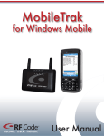
The A700 Room Locator by RF Code is an IR (infrared) signaling unit used with RF readers and IR-enabled active
tags to provide a method of locating and tracking tagged assets within a specified coverage area (for example, a
mid-sized 15-by-15-foot room). The system is not designed for localized coverage of very small areas (for example, a
2-by-2-foot space).
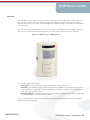
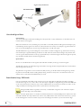
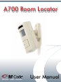
The A700 is housed in a plastic chassis 4.74” x 2.94” x 2.0” in size. A mounting bracket is included that allows the
unit to pivot. Two screws attach the mounting bracket to the wall, and then the A700 snaps into the bracket.
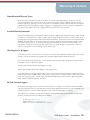
Figure 1.1 A700 Front View – LED Indicators
The A700 front panel features include:
• Green LED - The green LED (top left) will stay lit when the A700 is powered ON.
• Red LED - The red LED (top right) will flash the uniquely assigned ID one time when the A700 is powered
on. For example, for a unique ID of 072 the led will display a quick flash to represent zero, then flash seven
times, pause, and then flash two times.
• Rectangular
Window - This plastic window (upper half of the unit) is designed to help disperse the IR signal.
A bank of IR LEDs are situated behind this window.
Figure 1.2 shows the interior view of a A700 unit with a Power Jack, 4-Switch DIP (Power Level) and 10-Switch
DIP (Room Number Unique ID).
PN00084 REV01
A700 Room Locator User Manual 4
AssetTAsset
rackingSystem
Tracking
Process
Figure 1.2 A700 – Interior View
Asset Tracking System Process
The basic principle behind the asset tracking process involves A700 room locators, IR-enabled active tags, RF readers, and data collection software. A700 room locators are positioned in specific areas. Each A700 room locator emits
an infrared signal containing an uniquely assigned ID to identify itself. Active tags attached to assets search for this
signal that contains the unique ID. The active tags gather and transmit this unique ID along with additional information to an RF reader to report its current location and status. Data collection software interacts with the reader over a
network connection to gather information that active tags send to the reader.
It is the action of the IR-enabled active tags to find and synchronize with the A700s. Once a tag has synchronized
with a A700, the tag knows that additional messages from the same A700 will appear every second. If a tag cannot
detect an A700 signal, this information is relayed to the reader to indicate a possible problem. A moving tag will
check for its A700 every 3 seconds. If the tag fails to receive a signal at the expected time, it reverts back to search
mode.
When a tag has been stationary for at least 15 minutes and has seen no valid A700 during that time, it will go into a
“low power” mode and only check for A700s every 15 minutes. When a tag has been stationary for at least 1 minute
and has seen the same valid A700 during that time, it will go into a “low power” mode and only check for A700s
every 15 seconds.
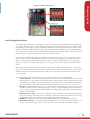
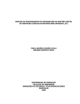
The Asset Tracking process is illustrated in Figure 1.3. Major components consist of the following:
1. A700
room locator – The A700 unit periodically sends out a short burst of infrared pulses to report a unique
ID assigned to an A700 to identify itself. Sending repetitive signal pulses also aid in avoiding interference with
other IR devices. A700 IDs can be used when placing A700 room locators in various locations and defining
area maps. Defining a unique ID is mentioned in the section titled “Room Number Setup - DIP Switch”.
2. IR
Signal – All IR-enabled active tags in a room look for this A700 infrared signal at specific intervals. These
intervals are based on the state of the tag (moving or stationary), as mentioned previously. The placement of
tags is essential to properly detect the infrared signals. For example, placing a tag inside a desk drawer will not
properly read the IR signal.
3. IR-Enabled Active Tags – Active tags are attached to assets to track the movement and current location of
those assets. The tags relay a RF beacon to a reader that contains the A700 location identifier seen by the tag.
The IR-enabled active tags communicate using the RF Code Treatment 04A protocol.
4. RF
Reader – The RF reader reads the data provided by the RF signals transmitted by the active tags.
5. Direct Reader Interface – An API interface is provided for users to write their own code that allows a connection to the reader through a network or serial connection, and to send and receive DSP commands.
PN00084 REV01
5
General/Special Notes
Figure 1.3 System Process
General and Special Notes
General Notes
The user should keep in mind when installing the A700 System that a variety of IR devices or other IR sources can
interfere with the A700 signals.
When such interference occurs, the IR tag may not be able to successfully decode the IR signal and will report a payload indicating that the tag does not detect any valid A700 units in the vicinity. For example, a tag placed within one
foot of a 65-watt floodlight may cause the tag to fail all decodes of an IR A700 signal.
The IR-enabled active tags are NOT designed to work outdoors. In direct sunlight, the tag will not detect A700 signals and will report a payload indicating the absence of valid A700 units. Some fluorescent lights may interfere with
an asset tag if the infrared window on the tag is pointed directly at a fluorescent light. If fluorescent lights are present,
tags should be attached with the window facing sideways.
Special Notes
Do not cover the IR window on the tag label. This will affect the ability of the tag to read A700 signals.
The RF field of the tags are affected by large metal surfaces. The tags should not be placed directly on metal surfaces
that are large relative to the tag.
The placement of tags within a room can affect the ability of the tag to decode infrared A700 signals. Tags should
be placed so that their IR window would typically be facing towards an A700, or have an unobstructed view of a
surface; such as a wall, that will be illuminated by an A700.
Room Number Setup - DIP Switch
One of a possible 495 unique ID’s can be assigned to an A700. These IDs are defined by three digits. Each digit
must be in the range of 0 to 7, such as 045 or 714. The unique 3-digit ID is configured using the 10-switch DIP bank
on the A700 circuit board. At this time, only 9 of the 10 DIP switches are used. These 9 switches are used to set the
3-digit A700 ID. The remaining switch (switch 10) must be left in the OFF position.
Setting the DIP switches is typically not necessary. A default ID is assigned to each A700 that is equal to
the last three digits of the serial number.
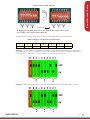
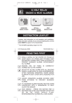
Flip the A700 unit upside down to see the direct correlation between the 10-Switch DIP positions and how the value
of the ID is defined. The unique ID for each A700 is set by 9 DIP switches with the first three switches (1,2,3) used
for the third digit, the next three switches (4,5,6) for the second digit, and switches 7,8, and 9 for the first digit.
6
PN00084 REV01
RoomAnd
Number
General
SpecialSetup
Notes
7
7
0
{
{
{
{
{
{
Figure 1.4 10-Switch DIP Positions
Assigned ID
0
7
7
By flipping the unit upside down you can determine the left to right order of the ID.
For example, a unit assigned a unique ID of 077.
To define the Room Number for an A700 unit, refer to the following table to set the DIP switches.
Table 1.1 ID Digits with Equivalent Switch Positions
1
off-off-off
2
off-off-on
3
off-on-off
4
on-off-off
5
on-off-on
6
on-on-off
7
on-on-on
Example 1 – A room number of 72 would be represented as a 3-digit ID of 072. After flipping the A700 upside
down, DIP switches 1, 2, and 3 would be set to off-on-off (represents 2) and switches 4, 5, and 6 would be set to onon-on (represents 7), and switches 7, 8, and 9 would be set to off-off-off (represents 0).
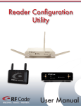
Example 2 – If the user wants to define a unique ID of 714 for an A700, then set the DIP switches as shown:
PN00084 REV01
7
There are 17 reserved IDs that the A700 can not be set to:
000, 760, 761, 762, 763, 764, 765, 766, 767, 770, 771, 772, 773, 774, 775, 776, 777
If set to one of these IDs, the red LED on the A700 will continue to blink quickly to indicate the problem.
Power Level Setup - DIP Switch
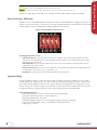
In addition to the 10-switch DIP bank, the A700 unit also carries a 4-switch DIP bank to configure the power level.
Each one of these four switches is connected to a row of three IR LED transmitters (situated behind the front-panel
window) yielding a total of 12 LEDs and providing four different levels of power.
Figure 1.5 Switch DIP to Set Power Level
To Configure The Power Level:
• One-Fourth
Power: To set the power level to 25% of full power, turn any one of the switches to the ON
position. It is recommended to use one of the middle switches (switch 2 or 3) to obtain a direct line-of-sight
between the tag and A700 unit.
• One-Half
Power: To set it to 50% of full power, turn any two of the switches to the ON position. It is recommended to use switch 2 and 3.
• Three-Fourths
Power: To set it to 75% of full power, turn any three of the switches to the ON position. It is
recommended to use switches 1, 2, 3 or switches 2, 3, 4.
• Full Power: For 100% power, all the switches must be in the ON position.
Optional Cabling
An optional cable is available to connect your power supply to multiple A700 units in parallel. You can use an RF
Code provided power supply with up to five A700 room locators and optional cable(s), provided you splice into the
power cable and make parallel connections to the optional cables and use cabling where the voltage drop is not significant. If using your own power supply, see the specifications below and consult an electrician about wire size and
run length to insure the voltage drop does not cause an input voltage outside of the specified limits.
Cable Input Specifications
• The A700 will operate with 15V to 24V at the input of the optional cable.
• The cable’s white lead is positive (+); black is negative (-)
• Regulated supply required: 15V to 24V
• Unregulated supply required: 12V to 18V (unregulated supply voltage drops with load)
• Current consumption 50mA average - 100mA peak per A700 Room Locator
• Cable length = ~12 feet
8
PN00084 REV01
Power Level Setup
Environmental Limits
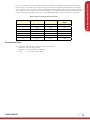
Up to five A700 locators can be powered by one RF Code provided 12V unregulated wall transformer by splicing
into the wiring. The user will need to design the wiring to comply with the cable input specifications. For example,
if five A700 locators are connected to one run of 2000 feet of 24 AWG cable on a 24V regulated supply, the voltage
drop would be too large and each A700 would receive under 15 Volts. The table below lists wire size and resistance
to aid in calculating voltage drop for long runs of cable. Remember Voltage = Current * Resistance or (V=I*R).
Table 1.2 Data for Voltage Drop Calculations
AWG
Diameter in inches
OHMS/1000 ft
14
16
18
20
22
24
26
0.0641
0.0508
0.0403
0.032
0.0254
0.0201
0.0159
2.525
4.016
6.385
10.15
16.14
25.67
40.81
MAX Current in
AMPs
5.9
3.7
2.3
1.5
0.92
0.577
0.361
Environmental Limits
The A700 unit is approved for use within the ranges set forth below.
• Operation: 10 to 50 degrees Celsius
• Humidity: 10% to 90% RH non-condensing
• Input:
15 to 24 VDC, 100mA MAX
PN00084 REV01
9
Warranty & Service
Limited Standard Warranty Terms
F Code warrants its products to be free from defects in materials and workmanship for a period of 1 year (12
R
months) for hardware and software from the date of purchase from RF Code. Its obligation under this warranty is
limited to repairing or replacing, at its own sole option, any such defective products. This warranty does not apply to
equipment that has been damaged by accident, negligence, or misapplication or has been altered or modified in any
way. This warranty applies only to the original purchaser (end-user) and is not transferable.
Standard Warranty Limitations
xcept as provided herein, the entire liability of RF Code and its suppliers under this limited warranty will be that RF
E
Code will use reasonable efforts to repair or replace, without charge, all defective Products returned to RF Code by
Customer, all as more particularly described in the End User Warranty. Except for the express warranties STATED
HEREIN, RF Code makes no other representations or warranties and RF Code hereby disclaims, all other warranties, express, implied, statutory, or otherwise, including without limitation, any warranty of merchantability, noninfringement of third party intellectual property rights, fitness for a particular purpose, performance, satisfactory
quality, or arising from a course of dealing, usage or trade practice.
Obtaining Service & Support
in-warranty service, customers have several options. Customers having difficulty with RF Code products should
For
attempt to solve those problems through RF Code’s Technical Support Problem Escalation Process:
irst, contact the RF Code representative or other distributor from whom the RF Code product was purchased for
F
information on how to obtain local support.
Second, contact the RF Code Customer Support via e-mail.
Third, contact the RF Code Customer Support via the Support Line.
or product returns, the support engineer will give you a return material authorization (RMA) number. No returns
F
will be accepted without an RMA number. If the warranty expired, there is a charge for repair or replacement per RF
Code’s out-of-warranty policy. For full details of the RF Code RMA policy, please review the “RF Code Warranty,
RMA, and Extended Warranty Policy” document.
RF Code Customer Support
F Code Customer Support gives entitled customers and partners the ability to contact RF Code about installation
R
and usage-related questions as well as make defect inquiries about eligible products that are covered under RF Code
warranty agreements. A team of technical specialists can be contacted electronically or via phone.
he Support Line is available to provide General Support during normal business hours: Monday through Friday,
T
8:00am to 5:00pm Central time, excluding national holidays.
PN00084 REV01
E-mail: [email protected]
Support form: http://www.rfcode.com
Voice: 512.439.2244 or toll-free at 866.830.4578
A700 Room Locator User Manual 10