1
MELSEC iQ-R Temperature Control Module
User's Manual (Startup)
-R60TCTRT2TT2
-R60TCTRT2TT2BW
-R60TCRT4
-R60TCRT4BW
SAFETY PRECAUTIONS
(Read these precautions before using this product.)
Before using this product, please read this manual and the relevant manuals carefully and pay full attention to safety to handle
the product correctly.
The precautions given in this manual are concerned with this product only. For the safety precautions of the programmable
controller system, refer to the MELSEC iQ-R Module Configuration Manual.
In this manual, the safety precautions are classified into two levels: "
WARNING" and "
CAUTION".
WARNING
Indicates that incorrect handling may cause hazardous conditions, resulting in
death or severe injury.
CAUTION
Indicates that incorrect handling may cause hazardous conditions, resulting in
minor or moderate injury or property damage.
Under some circumstances, failure to observe the precautions given under "
CAUTION" may lead to serious
consequences.
Observe the precautions of both levels because they are important for personal and system safety.
Make sure that the end users read this manual and then keep the manual in a safe place for future reference.
1
[Design Precautions]
WARNING
● Configure safety circuits external to the programmable controller to ensure that the entire system
operates safely even when a fault occurs in the external power supply or the programmable controller.
Failure to do so may result in an accident due to an incorrect output or malfunction.
(1) Emergency stop circuits, protection circuits, and protective interlock circuits for conflicting
operations (such as forward/reverse rotations or upper/lower limit positioning) must be configured
external to the programmable controller.
(2) When the programmable controller detects an abnormal condition, it stops the operation and all
outputs are:
• Turned off if the overcurrent or overvoltage protection of the power supply module is activated.
• Held or turned off according to the parameter setting if the self-diagnostic function of the CPU
module detects an error such as a watchdog timer error.
(3) All outputs may be turned on if an error occurs in a part, such as an I/O control part, where the
CPU module cannot detect any error. To ensure safety operation in such a case, provide a safety
mechanism or a fail-safe circuit external to the programmable controller. For a fail-safe circuit
example, refer to "General Safety Requirements" in the MELSEC iQ-R Module Configuration
Manual.
(4) Outputs may remain on or off due to a failure of a component such as a relay and transistor in an
output circuit. Configure an external circuit for monitoring output signals that could cause a
serious accident.
● In an output circuit, when a load current exceeding the rated current or an overcurrent caused by a
load short-circuit flows for a long time, it may cause smoke and fire. To prevent this, configure an
external safety circuit, such as a fuse.
● Configure a circuit so that the programmable controller is turned on first and then the external power
supply. If the external power supply is turned on first, an accident may occur due to an incorrect output
or malfunction.
● For the operating status of each station after a communication failure, refer to manuals relevant to the
network. Incorrect output or malfunction due to a communication failure may result in an accident.
● When connecting an external device with a CPU module or intelligent function module to modify data
of a running programmable controller, configure an interlock circuit in the program to ensure that the
entire system will always operate safely. For other forms of control (such as program modification,
parameter change, forced output, or operating status change) of a running programmable controller,
read the relevant manuals carefully and ensure that the operation is safe before proceeding. Improper
operation may damage machines or cause accidents.
● Especially, when a remote programmable controller is controlled by an external device, immediate
action cannot be taken if a problem occurs in the programmable controller due to a communication
failure. To prevent this, configure an interlock circuit in the program, and determine corrective actions
to be taken between the external device and CPU module in case of a communication failure.
● Do not write any data to the "system area" and "write-protect area" of the buffer memory in the
module. Also, do not use any "use prohibited" signals as an output signal from the CPU module to
each module. Doing so may cause malfunction of the programmable controller system. For the
"system area", "write-protect area", and the "use prohibited" signals, refer to the user's manual for the
module used.
2
[Design Precautions]
WARNING
● If a communication cable is disconnected, the network may be unstable, resulting in a communication
failure of multiple stations. Configure an interlock circuit in the program to ensure that the entire
system will always operate safely even if communications fail. Failure to do so may result in an
accident due to an incorrect output or malfunction.
● To maintain the safety of the programmable controller system against unauthorized access from
external devices via the network, take appropriate measures. To maintain the safety against
unauthorized access via the Internet, take measures such as installing a firewall.
[Design Precautions]
CAUTION
● Do not install the control lines or communication cables together with the main circuit lines or power
cables. Keep a distance of 100mm or more between them. Failure to do so may result in malfunction
due to noise.
● During control of an inductive load such as a lamp, heater, or solenoid valve, a large current
(approximately ten times greater than normal) may flow when the output is turned from off to on.
Therefore, use a module that has a sufficient current rating.
● After the CPU module is powered on or is reset, the time taken to enter the RUN status varies
depending on the system configuration, parameter settings, and/or program size. Design circuits so
that the entire system will always operate safely, regardless of the time.
● Do not power off the programmable controller or reset the CPU module while the settings are being
written. Doing so will make the data in the flash ROM undefined. The values need to be set in the
buffer memory and written to the flash ROM again. Doing so also may cause malfunction or failure of
the module.
● When changing the operating status of the CPU module from external devices (such as the remote
RUN/STOP functions), select "Do Not OPEN in Program" for "Open Method Setting" in the module
parameters. If "OPEN in Program" is selected, an execution of the remote STOP function causes the
communication line to close. Consequently, the CPU module cannot reopen the line, and external
devices cannot execute the remote RUN function.
3
[Installation Precautions]
WARNING
● Shut off the external power supply (all phases) used in the system before mounting or removing the
module. Failure to do so may result in electric shock or cause the module to fail or malfunction.
[Installation Precautions]
CAUTION
● Use the programmable controller in an environment that meets the general specifications in the Safety
Guidelines included with the base unit. Failure to do so may result in electric shock, fire, malfunction,
or damage to or deterioration of the product.
● To mount a module, place the concave part(s) located at the bottom onto the guide(s) of the base unit,
and push in the module until the hook(s) located at the top snaps into place. Incorrect interconnection
may cause malfunction, failure, or drop of the module.
● When using the programmable controller in an environment of frequent vibrations, fix the module with
a screw.
● Tighten the screws within the specified torque range. Undertightening can cause drop of the screw,
short circuit, or malfunction. Overtightening can damage the screw and/or module, resulting in drop,
short circuit, or malfunction.
● When using an extension cable, connect it to the extension cable connector of the base unit securely.
Check the connection for looseness. Poor contact may cause malfunction.
● When using an SD memory card, fully insert it into the SD memory card slot. Check that it is inserted
completely. Poor contact may cause malfunction.
● Securely insert an extended SRAM cassette into the cassette connector of the CPU module. After
insertion, close the cassette cover and check that the cassette is inserted completely. Poor contact
may cause malfunction.
● Do not directly touch any conductive parts and electronic components of the module, SD memory
card, extended SRAM cassette, or connector. Doing so can cause malfunction or failure of the
module.
[Wiring Precautions]
WARNING
● Shut off the external power supply (all phases) used in the system before installation and wiring.
Failure to do so may result in electric shock or cause the module to fail or malfunction.
● After installation and wiring, attach the included terminal cover to the module before turning it on for
operation. Failure to do so may result in electric shock.
4
[Wiring Precautions]
CAUTION
● Individually ground the FG and LG terminals of the programmable controller with a ground resistance
of 100 ohms or less. Failure to do so may result in electric shock or malfunction.
● Use applicable solderless terminals and tighten them within the specified torque range. If any spade
solderless terminal is used, it may be disconnected when the terminal screw comes loose, resulting in
failure.
● Check the rated voltage and signal layout before wiring to the module, and connect the cables
correctly. Connecting a power supply with a different voltage rating or incorrect wiring may cause fire
or failure.
● Connectors for external devices must be crimped or pressed with the tool specified by the
manufacturer, or must be correctly soldered. Incomplete connections may cause short circuit, fire, or
malfunction.
● Securely connect the connector to the module. Poor contact may cause malfunction.
● Do not install the control lines or communication cables together with the main circuit lines or power
cables. Keep a distance of 100mm or more between them. Failure to do so may result in malfunction
due to noise.
● Place the cables in a duct or clamp them. If not, dangling cable may swing or inadvertently be pulled,
resulting in damage to the module or cables or malfunction due to poor contact. Do not clamp the
extension cables with the jacket stripped.
● Check the interface type and correctly connect the cable. Incorrect wiring (connecting the cable to an
incorrect interface) may cause failure of the module and external device.
● Tighten the terminal screws or connector screws within the specified torque range. Undertightening
can cause drop of the screw, short circuit, fire, or malfunction. Overtightening can damage the screw
and/or module, resulting in drop, short circuit, fire, or malfunction.
● When disconnecting the cable from the module, do not pull the cable by the cable part. For the cable
with connector, hold the connector part of the cable. For the cable connected to the terminal block,
loosen the terminal screw. Pulling the cable connected to the module may result in malfunction or
damage to the module or cable.
● Prevent foreign matter such as dust or wire chips from entering the module. Such foreign matter can
cause a fire, failure, or malfunction.
● A protective film is attached to the top of the module to prevent foreign matter, such as wire chips,
from entering the module during wiring. Do not remove the film during wiring. Remove it for heat
dissipation before system operation.
● Programmable controllers must be installed in control panels. Connect the main power supply to the
power supply module in the control panel through a relay terminal block. Wiring and replacement of a
power supply module must be performed by qualified maintenance personnel with knowledge of
protection against electric shock. For wiring, refer to the MELSEC iQ-R Module Configuration Manual.
● For Ethernet cables to be used in the system, select the ones that meet the specifications in the user's
manual for the module used. If not, normal data transmission is not guaranteed.
5
[Wiring Precautions]
CAUTION
● Individually ground the shielded cables of the programmable controller with a ground resistance of
100 ohms or less. Failure to do so may result in electric shock or malfunction.
[Startup and Maintenance Precautions]
WARNING
● Do not touch any terminal while power is on. Doing so will cause electric shock or malfunction.
● Correctly connect the battery connector. Do not charge, disassemble, heat, short-circuit, solder, or
throw the battery into the fire. Also, do not expose it to liquid or strong shock. Doing so will cause the
battery to produce heat, explode, ignite, or leak, resulting in injury and fire.
● Shut off the external power supply (all phases) used in the system before cleaning the module or
retightening the terminal screws, connector screws, or module fixing screws. Failure to do so may
result in electric shock.
6
[Startup and Maintenance Precautions]
CAUTION
● When connecting an external device with a CPU module or intelligent function module to modify data
of a running programmable controller, configure an interlock circuit in the program to ensure that the
entire system will always operate safely. For other forms of control (such as program modification,
parameter change, forced output, or operating status change) of a running programmable controller,
read the relevant manuals carefully and ensure that the operation is safe before proceeding. Improper
operation may damage machines or cause accidents.
● Especially, when a remote programmable controller is controlled by an external device, immediate
action cannot be taken if a problem occurs in the programmable controller due to a communication
failure. To prevent this, configure an interlock circuit in the program, and determine corrective actions
to be taken between the external device and CPU module in case of a communication failure.
● Do not disassemble or modify the modules. Doing so may cause failure, malfunction, injury, or a fire.
● Use any radio communication device such as a cellular phone or PHS (Personal Handy-phone
System) more than 25cm away in all directions from the programmable controller. Failure to do so
may cause malfunction.
● Shut off the external power supply (all phases) used in the system before mounting or removing the
module. Failure to do so may cause the module to fail or malfunction.
● Tighten the screws within the specified torque range. Undertightening can cause drop of the
component or wire, short circuit, or malfunction. Overtightening can damage the screw and/or module,
resulting in drop, short circuit, or malfunction.
● After the first use of the product, do not mount/remove the module to/from the base unit, and the
terminal block to/from the module, and do not insert/remove the extended SRAM cassette to/from the
CPU module more than 50 times (IEC 61131-2 compliant) respectively. Exceeding the limit may cause
malfunction.
● After the first use of the product, do not insert/remove the SD memory card to/from the CPU module
more than 500 times. Exceeding the limit may cause malfunction.
● Do not touch the metal terminals on the back side of the SD memory card. Doing so may cause
malfunction or failure of the module.
● Do not touch the integrated circuits on the circuit board of an extended SRAM cassette. Doing so may
cause malfunction or failure of the module.
● Do not drop or apply shock to the battery to be installed in the module. Doing so may damage the
battery, causing the battery fluid to leak inside the battery. If the battery is dropped or any shock is
applied to it, dispose of it without using.
● Startup and maintenance of a control panel must be performed by qualified maintenance personnel
with knowledge of protection against electric shock. Lock the control panel so that only qualified
maintenance personnel can operate it.
● Before handling the module, touch a conducting object such as a grounded metal to discharge the
static electricity from the human body. Failure to do so may cause the module to fail or malfunction.
7
[Operating Precautions]
CAUTION
● When changing data and operating status, and modifying program of the running programmable
controller from an external device such as a personal computer connected to an intelligent function
module, read relevant manuals carefully and ensure the safety before operation. Incorrect change or
modification may cause system malfunction, damage to the machines, or accidents.
● Do not power off the programmable controller or reset the CPU module while the setting values in the
buffer memory are being written to the flash ROM in the module. Doing so will make the data in the
flash ROM undefined. The values need to be set in the buffer memory and written to the flash ROM
again. Doing so can cause malfunction or failure of the module.
[Disposal Precautions]
CAUTION
● When disposing of this product, treat it as industrial waste.
● When disposing of batteries, separate them from other wastes according to the local regulations. For
details on battery regulations in EU member states, refer to the MELSEC iQ-R Module Configuration
Manual.
[Transportation Precautions]
CAUTION
● When transporting lithium batteries, follow the transportation regulations. For details on the regulated
models, refer to the MELSEC iQ-R Module Configuration Manual.
● The halogens (such as fluorine, chlorine, bromine, and iodine), which are contained in a fumigant
used for disinfection and pest control of wood packaging materials, may cause failure of the product.
Prevent the entry of fumigant residues into the product or consider other methods (such as heat
treatment) instead of fumigation. The disinfection and pest control measures must be applied to
unprocessed raw wood.
8
CONDITIONS OF USE FOR THE PRODUCT
(1) Mitsubishi programmable controller ("the PRODUCT") shall be used in conditions;
i) where any problem, fault or failure occurring in the PRODUCT, if any, shall not lead to any major or serious accident;
and
ii) where the backup and fail-safe function are systematically or automatically provided outside of the PRODUCT for the
case of any problem, fault or failure occurring in the PRODUCT.
(2) The PRODUCT has been designed and manufactured for the purpose of being used in general industries.
MITSUBISHI SHALL HAVE NO RESPONSIBILITY OR LIABILITY (INCLUDING, BUT NOT LIMITED TO ANY AND ALL
RESPONSIBILITY OR LIABILITY BASED ON CONTRACT, WARRANTY, TORT, PRODUCT LIABILITY) FOR ANY
INJURY OR DEATH TO PERSONS OR LOSS OR DAMAGE TO PROPERTY CAUSED BY the PRODUCT THAT ARE
OPERATED OR USED IN APPLICATION NOT INTENDED OR EXCLUDED BY INSTRUCTIONS, PRECAUTIONS, OR
WARNING CONTAINED IN MITSUBISHI'S USER, INSTRUCTION AND/OR SAFETY MANUALS, TECHNICAL
BULLETINS AND GUIDELINES FOR the PRODUCT.
("Prohibited Application")
Prohibited Applications include, but not limited to, the use of the PRODUCT in;
• Nuclear Power Plants and any other power plants operated by Power companies, and/or any other cases in which the
public could be affected if any problem or fault occurs in the PRODUCT.
• Railway companies or Public service purposes, and/or any other cases in which establishment of a special quality
assurance system is required by the Purchaser or End User.
• Aircraft or Aerospace, Medical applications, Train equipment, transport equipment such as Elevator and Escalator,
Incineration and Fuel devices, Vehicles, Manned transportation, Equipment for Recreation and Amusement, and
Safety devices, handling of Nuclear or Hazardous Materials or Chemicals, Mining and Drilling, and/or other
applications where there is a significant risk of injury to the public or property.
Notwithstanding the above, restrictions Mitsubishi may in its sole discretion, authorize use of the PRODUCT in one or
more of the Prohibited Applications, provided that the usage of the PRODUCT is limited only for the specific
applications agreed to by Mitsubishi and provided further that no special quality assurance or fail-safe, redundant or
other safety features which exceed the general specifications of the PRODUCTs are required. For details, please
contact the Mitsubishi representative in your region.
9
INTRODUCTION
Thank you for purchasing the Mitsubishi MELSEC iQ-R series programmable controllers.
This manual describes the performance specifications, procedures before operation, wiring, and operation examples of the
relevant products listed below.
Before using this product, please read this manual and the relevant manuals carefully and develop familiarity with the
functions and performance of the MELSEC iQ-R series programmable controller to handle the product correctly.
When applying the program and circuit examples provided in this manual to an actual system, ensure the applicability and
confirm that it will not cause system control problems.
Please make sure that the end users read this manual.
Unless otherwise specified, this manual provides program examples in which the I/O numbers of X/Y0 to X/YF
are assigned to the temperature control module. Assign I/O numbers when applying the program examples to
an actual system. For I/O number assignment, refer to the following.
MELSEC iQ-R Module Configuration Manual
Relevant products
R60TCTRT2TT2, R60TCTRT2TT2BW, R60TCRT4, R60TCRT4BW
COMPLIANCE WITH EMC AND LOW VOLTAGE
DIRECTIVES
Method of ensuring compliance
To ensure that Mitsubishi programmable controllers maintain EMC and Low Voltage Directives when incorporated into other
machinery or equipment, certain measures may be necessary. Please refer to one of the following manuals.
• MELSEC iQ-R Module Configuration Manual
• Safety Guidelines (This manual is included with the base unit.)
The CE mark on the side of the programmable controller indicates compliance with EMC and Low Voltage Directives.
Additional measures
To ensure that this product maintains EMC and Low Voltage Directives, please refer to one of the following manuals.
• MELSEC iQ-R Module Configuration Manual
• Safety Guidelines (This manual is included with the base unit.)
10
CONTENTS
SAFETY PRECAUTIONS . . . . . . . . . . . . . . . . . . . . . . . . . . . . . . . . . . . . . . . . . . . . . . . . . . . . . . . . . . . . . . . . . . . .1
CONDITIONS OF USE FOR THE PRODUCT . . . . . . . . . . . . . . . . . . . . . . . . . . . . . . . . . . . . . . . . . . . . . . . . . . . .9
INTRODUCTION . . . . . . . . . . . . . . . . . . . . . . . . . . . . . . . . . . . . . . . . . . . . . . . . . . . . . . . . . . . . . . . . . . . . . . . . . .10
COMPLIANCE WITH EMC AND LOW VOLTAGE DIRECTIVES . . . . . . . . . . . . . . . . . . . . . . . . . . . . . . . . . . . . .10
RELEVANT MANUALS . . . . . . . . . . . . . . . . . . . . . . . . . . . . . . . . . . . . . . . . . . . . . . . . . . . . . . . . . . . . . . . . . . . . .13
CHAPTER 1
PART NAMES
15
CHAPTER 2
SPECIFICATIONS
17
2.1
Performance Specifications . . . . . . . . . . . . . . . . . . . . . . . . . . . . . . . . . . . . . . . . . . . . . . . . . . . . . . . . . . . . . . . 17
2.2
Type of Temperature Sensors, Temperature Measuring Range, Resolution, and Effect from Wiring
Resistance . . . . . . . . . . . . . . . . . . . . . . . . . . . . . . . . . . . . . . . . . . . . . . . . . . . . . . . . . . . . . . . . . . . . . . . . . . . . . 19
CHAPTER 3
FUNCTION LIST
21
CHAPTER 4
PROCEDURES BEFORE OPERATION
24
CHAPTER 5
SYSTEM CONFIGURATION
26
5.1
Precautions for System Configuration . . . . . . . . . . . . . . . . . . . . . . . . . . . . . . . . . . . . . . . . . . . . . . . . . . . . . . 26
CHAPTER 6
INSTALLATION AND WIRING
28
6.1
Terminal Block . . . . . . . . . . . . . . . . . . . . . . . . . . . . . . . . . . . . . . . . . . . . . . . . . . . . . . . . . . . . . . . . . . . . . . . . . . 28
6.2
Wiring Precautions . . . . . . . . . . . . . . . . . . . . . . . . . . . . . . . . . . . . . . . . . . . . . . . . . . . . . . . . . . . . . . . . . . . . . . 36
6.3
CONTENTS
TERMS . . . . . . . . . . . . . . . . . . . . . . . . . . . . . . . . . . . . . . . . . . . . . . . . . . . . . . . . . . . . . . . . . . . . . . . . . . . . . . . . .14
External Wiring . . . . . . . . . . . . . . . . . . . . . . . . . . . . . . . . . . . . . . . . . . . . . . . . . . . . . . . . . . . . . . . . . . . . . . . . . 37
R60TCTRT2TT2 . . . . . . . . . . . . . . . . . . . . . . . . . . . . . . . . . . . . . . . . . . . . . . . . . . . . . . . . . . . . . . . . . . . . . . . . . 37
R60TCTRT2TT2BW . . . . . . . . . . . . . . . . . . . . . . . . . . . . . . . . . . . . . . . . . . . . . . . . . . . . . . . . . . . . . . . . . . . . . . 40
R60TCRT4 . . . . . . . . . . . . . . . . . . . . . . . . . . . . . . . . . . . . . . . . . . . . . . . . . . . . . . . . . . . . . . . . . . . . . . . . . . . . . 43
R60TCRT4BW. . . . . . . . . . . . . . . . . . . . . . . . . . . . . . . . . . . . . . . . . . . . . . . . . . . . . . . . . . . . . . . . . . . . . . . . . . . 45
6.4
Heater Disconnection Detection Wiring and Setting Example for Three-phase Heater . . . . . . . . . . . . . . . 47
6.5
Unused Channel Setting . . . . . . . . . . . . . . . . . . . . . . . . . . . . . . . . . . . . . . . . . . . . . . . . . . . . . . . . . . . . . . . . . . 48
CHAPTER 7
OPERATION EXAMPLES
49
7.1
Programming Procedure . . . . . . . . . . . . . . . . . . . . . . . . . . . . . . . . . . . . . . . . . . . . . . . . . . . . . . . . . . . . . . . . . 49
7.2
Program Examples . . . . . . . . . . . . . . . . . . . . . . . . . . . . . . . . . . . . . . . . . . . . . . . . . . . . . . . . . . . . . . . . . . . . . . 49
Standard control . . . . . . . . . . . . . . . . . . . . . . . . . . . . . . . . . . . . . . . . . . . . . . . . . . . . . . . . . . . . . . . . . . . . . . . . . 49
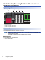
Standard control (When using the inter-module simultaneous temperature rise function) . . . . . . . . . . . . . . . . . 56
Standard control (When using the inter-module peak current suppression function) . . . . . . . . . . . . . . . . . . . . . 62
Heating-cooling control . . . . . . . . . . . . . . . . . . . . . . . . . . . . . . . . . . . . . . . . . . . . . . . . . . . . . . . . . . . . . . . . . . . . 68
Position proportional control . . . . . . . . . . . . . . . . . . . . . . . . . . . . . . . . . . . . . . . . . . . . . . . . . . . . . . . . . . . . . . . . 71
APPENDIX
74
Appendix 1 External Dimensions . . . . . . . . . . . . . . . . . . . . . . . . . . . . . . . . . . . . . . . . . . . . . . . . . . . . . . . . . . . . . . . . 74
INDEX
76
REVISIONS . . . . . . . . . . . . . . . . . . . . . . . . . . . . . . . . . . . . . . . . . . . . . . . . . . . . . . . . . . . . . . . . . . . . . . . . . . . . . .78
WARRANTY . . . . . . . . . . . . . . . . . . . . . . . . . . . . . . . . . . . . . . . . . . . . . . . . . . . . . . . . . . . . . . . . . . . . . . . . . . . . .79
11
TRADEMARKS . . . . . . . . . . . . . . . . . . . . . . . . . . . . . . . . . . . . . . . . . . . . . . . . . . . . . . . . . . . . . . . . . . . . . . . . . . .80
12
RELEVANT MANUALS
Manual name [manual number]
Description
Available form
MELSEC iQ-R Temperature Control Module User's
Manual (Startup)
[SH-081535ENG] (this manual)
Specifications, procedures before operation, wiring, and
operation examples of the temperature control module
Print book
MELSEC iQ-R Temperature Control Module User's
Manual (Application)
[SH-081536ENG]
Functions, parameter settings, troubleshooting, I/O signals, and
buffer memory of the temperature control module
Print book
e-Manual
EPUB
PDF
e-Manual
EPUB
PDF
This manual does not include detailed information on the following:
• General specifications
• Applicable CPU modules and the number of mountable modules
• Installation
For details, refer to the following.
MELSEC iQ-R Module Configuration Manual
This manual does not include information on the module function blocks.
For details, refer to the Function Block Reference for the module used.
e-Manual refers to the Mitsubishi FA electronic book manuals that can be browsed using a dedicated tool.
e-Manual has the following features:
• Required information can be cross-searched in multiple manuals.
• Other manuals can be accessed from the links in the manual.
• The hardware specifications of each part can be found from the product figures.
• Pages that users often browse can be bookmarked.
13
TERMS
Unless otherwise specified, this manual uses the following terms.
14
Term
Description
Buffer memory
The intelligent function module's memory where the data (such as setting values and monitored values) transferred
from/to the CPU module is stored
Control method
The generic term of two-position control, P control, PI control, PD control, and PID control
Control mode
The generic term of standard control, heating-cooling control (normal mode), heating-cooling control (expanded mode),
mix control (normal mode), mix control (expanded mode), position proportional control (normal mode), and position
proportional control (expanded mode)
CPU module
The generic term of MELSEC iQ-R series CPU modules
Engineering tool
The product name of the MELSEC programmable controller software package
Fixed value action
The operating status of when a constant set value (SV) is kept
Global label
When multiple program data sets are created in a project, this label is valid for all the data sets. Global labels are
classified into two types: Module-specific labels (module labels) that are automatically created by GX Works3 and labels
that can be created for a specified device.
Module label
The memory areas that are defined by each module (I/O signals or buffer memory area) and expressed with character
strings. GX Works3 automatically creates module labels from the module to be used. These labels can be used as
global labels.
PID constants
The generic term of the proportional band (P), integral time (I), and derivative time (D)
Q compatible mode
The buffer memory map is converted into the one for the MELSEC-Q series to operate the module.
R mode
In this mode, the module operates with the buffer memory map that has been newly assigned for the MELSEC iQ-R
series.
Ramp action
The operating status of when a set value (SV) always changes
Temperature sensor
The generic term of thermocouples and platinum resistance thermometers
1
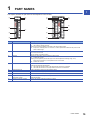
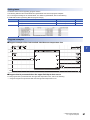
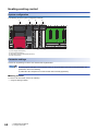
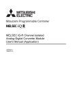
PART NAMES
1
This chapter describes the part names of the temperature control module.
(1)
(2)
(1)
(2)
(3)
(4)
(3)
(5)
(6)
(5)
(7)
(7)
(8)
(8)
(9)
(9)
No.
Name
Description
(1)
RUN LED
Indicates the operating status of the temperature control module.
On: The module is operating normally.
Flashing: The module is selected as a module for the online module change.
Off: 5V power off, watchdog timer error occurred, or module replacement is allowed in the process of the
online module change
(2)
ERR LED
Indicates the error status of the temperature control module.
On: An error has occurred.
Off: The module is operating normally.
(3)
ALM LED
Indicates the alarm status of the temperature control module.
On: An alert has occurred.
Flashing: The temperature process value (PV) is out of the temperature measuring range, a loop
disconnection is detected, or no temperature sensor is connected.
Off: No alert has occurred.
(4)
HBA LED
Indicates the heater disconnection detection status or the output off-time current error status of the
R60TCTRT2TT2BW and R60TCRT4BW.
On: The heater disconnection status or the output off-time current error is detected.
Off: The heater disconnection or the output off-time current error is not detected.
(5)
Terminal block for I/O
Used for temperature sensor input and transistor output.
(6)
Terminal block for CT
Used for current sensor (CT) input.
(7)
Terminal block cover
Prevents electric shock when current is applied.
(8)
Cold junction temperature
compensation resistor
Used when cold junction temperature compensation is executed for the R60TCTRT2TT2 and
R60TCTRT2TT2BW.
(9)
Production information marking
Displays the module production information (16 digits).
1 PART NAMES
15
MEMO
16
1 PART NAMES
2
SPECIFICATIONS
This chapter describes the performance specifications.
2.1
2
Performance Specifications
The following table lists the performance specifications of the temperature control module.
Item
R60TCTRT2TT2
Control output
Transistor output
R60TCRT4
R60TCTRT2TT2BW
R60TCRT4BW
Number of temperature input points
4 channels/module
Applicable thermocouple/platinum resistance thermometer
Refer to the following.
Page 19 Type of Temperature Sensors, Temperature Measuring Range, Resolution,
and Effect from Wiring Resistance
Accuracy*1
Ambient temperature:
255
Full scale (0.3%)
Ambient temperature: 0 to
55
Full scale (0.7%)
Temperature process
value: -100 or higher
Within 1.0
Temperature process
value: -150 to -100
Within 2.0
Within 2.0
Temperature process
value: -200 to -150
Within 3.0
Within 3.0
Indication accuracy
Cold junction
temperature
compensation
accuracy (Ambient
temperature: 0 to
55)
Within 1.0
Sampling cycle
Switchable between 250ms/4 channels and 500ms/4 channels
Control output cycle
0.5 to 100.0s
Input impedance
1M
Input filter
0 to 100s (0: Input filter OFF)
Sensor correction value setting
■When the R mode is used
(-(full scale of input range)) to full scale of input range
■When the Q compatible mode function is used
-50.00 to 50.00%
Operation at a sensor input disconnection
Upscale processing
Temperature control method
PID ON/OFF pulse or two-position control
PID constants
range
PID constants setting
Setting by auto tuning is available.
Proportional band (P)
■When the R mode is used
0 (0.0) to full scale of input range (depending on the decimal point position) (0: Twoposition control)
■When the Q compatible mode function is used
0.0 to 1000.0% (0: Two-position control)
Integral time (I)
0 to 3600s (Set 0 for P control and PD control.)
Derivative time (D)
0 to 3600s (Set 0 for P control and PI control.)
Set value setting range
Within the temperature range set in the thermocouple/platinum resistance thermometer to
be used
Dead band setting range
■When the R mode is used
0 (0.0) to full scale of input range (depending on the decimal point position)
■When the Q compatible mode function is used
0.1 to 10.0%
Transistor
output
Output signal
ON/OFF pulse
Rated load voltage
10 to 30VDC
Maximum load current
0.1A/point, 0.4A/common
Maximum inrush current
0.4A, 10ms
Leakage current at OFF
0.1mA or lower
Maximum voltage drop at ON
1.0VDC (TYP) 0.1A, 2.5VDC (MAX) 0.1A
Response time
OFFON: 2ms or less, ONOFF: 2ms or less
Number of accesses to non-volatile memory
1012 times maximum
Insulation method
Between the input terminal and PLC power supply: Transformer
Between input channels: Transformer
2 SPECIFICATIONS
2.1 Performance Specifications
17
Item
R60TCTRT2TT2
Withstand voltage
Between input terminals and programmable controller power supply: 500VAC, 1 minute
Between input channels: 500VAC, 1 minute
Insulation resistance
Between input terminals and programmable controller power supply: 500VDC, 20M or
higher
Between input channels: 500VDC, 20M or higher
Heater
disconnection
detection
specifications
Current sensor
R60TCRT4
R60TCTRT2TT2BW
R60TCRT4BW
Refer to the following.
Page 26 Current sensor for heater
disconnection detection
Full scale (1.0%)
Input accuracy
Number of alert delay
3 to 255 times
Number of occupied I/O points
16 points, 1 slot (I/O assignment:
intelligent 16 points)
32 points, 2 slots (I/O assignment: empty 16
points + intelligent 16 points)
External connection system
18-point terminal block
18-point terminal block 2
0.75mm2
Applicable wire size
0.3 to
Applicable solderless terminal
R1.25-3 (The solderless terminal with an insulation sleeve cannot be used.)
Internal current consumption
0.28A
Weight
External
dimensions
*1
(22 to 18 AWG)
0.31A
0.22kg
0.34kg
Height
106mm (Base unit mounting part:
98mm)
106mm (Base unit mounting part: 98mm)
Width
27.8mm
56mm
Depth
110mm
110mm
Except for the conditions under noise influence
For the noise immunity, withstand voltage, insulation resistance, and others in a programmable controller system which uses
a temperature control module, refer to the following.
MELSEC iQ-R Module Configuration Manual
How to calculate the accuracy
Calculate the accuracy in the following method.
Accuracy () = full scale indication accuracy + cold junction temperature compensation accuracy
Ex.
Accuracy at the input range set to "38: Thermocouple K Measured Temperature Range (-200.0 to 400.0)", operating
ambient temperature of 35, and the temperature process value (PV) of 300
(full scale) (indication accuracy) + (cold junction temperature compensation accuracy)
= (400.0 - (-200.0)) (0.007) + (1.0)
= 5.2
18
2 SPECIFICATIONS
2.1 Performance Specifications
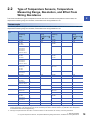
2.2
Type of Temperature Sensors, Temperature
Measuring Range, Resolution, and Effect from
Wiring Resistance
2
This section describes the types of temperature sensors that can be used with the temperature control module, the
temperature measuring range, the resolution, and the effect from wiring resistance of 1
Thermocouple
The following table lists the types of thermocouples that can be used with the R60TCTRT2TT2 and R60TCTRT2TT2BW, the
temperature measuring range, the resolution, and the effect from wiring resistance of 1.
Thermocouple
type
Temperature
measuring
range
Resolution
Effect from
wiring
resistance of 1
(/)*1
Temperature
measuring
range
Resolution
Effect from
wiring
resistance of 1
(/)*1
R
0 to 1700
1
0.030
0 to 3000
1
0.054
K
0 to 500
0 to 800
0 to 1300
1
0.005
0 to 1000
0 to 2400
1
0.008
-200.0 to 400.0
0.0 to 400.0
0.0 to 500.0
0.0 to 800.0
-200.0 to 1300.0
0.1
0.0 to 1000.0
0.1
0 to 500
0 to 800
0 to 1200
1
0 to 1000
0 to 1600
0 to 2100
1
0.0 to 400.0
0.0 to 500.0
0.0 to 800.0
-200.0 to 1000.0
0.1
0.0 to 1000.0
0.1
-200 to 400
-200 to 200
0 to 200
0 to 400
1
0 to 700
-300 to 400
1
-200.0 to 400.0
0.0 to 400.0
0.1
0.0 to 700.0
0.1
0 to 1700
1
0 to 3000
1
J
T
S
*2
0.003
0.004
0.030
*2
0.006
0.008
0.054
B
0 to 1800
1
0.038
0 to 3000
1
0.068
E
0 to 400
0 to 1000
1
0.003
0 to 1800
1
0.005
0.0 to 700.0
-200.0 to 1000.0
0.1
N
0 to 1300
1
0.0 to 1000.0
0.1
U
0 to 400
-200 to 200
1
0.0 to 600.0
0.1
L
0 to 400
0 to 900
1
0.0 to 400.0
0.0 to 900.0
0.1
0.006
0 to 2300
1
0.011
0.004
0 to 700
-300 to 400
1
0.009
0.003
0 to 800
0 to 1600
1
0.006
PL
0 to 1200
1
0.005
0 to 2300
1
0.010
W5Re/W26Re
0 to 2300
1
0.017
0 to 3000
1
0.021
*1
*2
Means temperature error per of wiring resistance of the thermocouple. The error varies depending on measured temperature or
ambient temperature. The temperature error can be corrected by the sensor correction function. ( MELSEC iQ-R Temperature
Control Module User's Manual (Application))
Although a temperature lower than 400 or lower than 800 can be measured, the accuracy cannot be guaranteed.
2 SPECIFICATIONS
2.2 Type of Temperature Sensors, Temperature Measuring Range, Resolution, and Effect from Wiring Resistance
19
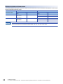
Platinum resistance thermometer
The following table lists the types of platinum resistance thermometers that can be used with the temperature control module
and the temperature measuring range.
Platinum resistance
thermometer type
Temperature measuring
range
Resolution
Temperature measuring
range
Resolution
Pt100
-200.0 to 600.0
-200.0 to 200.0
-200.0 to 850.0
0.1
-300 to 1100
1
-300.0 to 300.0
0.1
-200.0 to 500.0
-200.0 to 200.0
-200.0 to 640.0
0.1
-300 to 900
1
-300.0 to 300.0
0.1
JPt100
For the R60TCTRT2TT2 and R60TCTRT2TT2BW, only CH1 and CH2 can be used.
20
2 SPECIFICATIONS
2.2 Type of Temperature Sensors, Temperature Measuring Range, Resolution, and Effect from Wiring Resistance
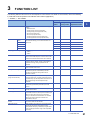
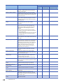
3
FUNCTION LIST
The following table lists the functions of the temperature control module. For details on each function, refer to the following.
MELSEC iQ-R Temperature Control Module User's Manual (Application)
: Available, : Not available
Item
Description
Availability
Standard
control
Heatingcooling control
Position
proportional control
Control mode selection function
A control mode can be selected from the following
modes.
• Standard control
• Heating-cooling control (normal mode)
• Heating-cooling control (expanded mode)
• Mix control (normal mode)
• Mix control (expanded mode)
• Position proportional control (normal mode)
• Position proportional control (expanded mode)
Control method
By the settings of proportional band (P), integral time (I),
and derivative time (D), each control method can be
performed
PI control
PD control
PID control
Two-position
control
P control
Sampling cycle switching function
A sampling cycle can be selected from the following.
• 500ms
• 250ms
HOLD/CLEAR function
Whether to clear or hold the transistor output status
when a CPU module stop error occurs or when a CPU
module is turned from RUN to STOP can be selected.
Overlap/dead band function
By changing the temperature where the cooling
transistor output is started, whether control stability is
prioritized or energy saving is prioritized can be
selected.
Manual reset function
This function is used to manually move a stable position
in the P control or PD control.
Cooling method setting function
At the execution of auto tuning, an auto tuning
operational expression is automatically selected
according to a selected cooling method and an
operation is started.
Temperature conversion function
(using unused channels)
In the heating-cooling control (normal mode), mix
control (normal mode), or position proportional control
(normal mode), only the temperature measurement can
be performed using unused temperature input
terminals.
Manual control
A manipulated value (MV) can be set manually by users
without being automatically calculated by the PID
control.
Auto tuning function
The temperature control module automatically sets
suitable PID constants.
Self-tuning function
The temperature control module constantly monitors the
control state. When the control system is oscillatory just
after the control start, owing to the set value (SV)
change or fluctuation of characteristics of a controlled
object, this function allows PID constants to be
automatically changed.
Direct/reverse action selection
function
Whether to execute a PID operation with a direct action
or a reverse action can be selected.
RFB limiter function
When deviation (E) continues for a long period of time,
this function prevents the PID operation results
(manipulated value (MV)) calculated by integral actions
from exceeding the effective range of the manipulated
value (MV).
3 FUNCTION LIST
3
21
Item
22
Description
Availability
Standard
control
Heatingcooling control
Position
proportional control
Derivative action selection function
This function improves dynamic characteristics by
selecting a suitable derivative action for fixed value
actions or ramp actions.
Simple two-degree-of-freedom
In addition to the PID control, this function selects a
suitable response speed for the set value (SV) change
from three levels to simply achieve the two-degree-offreedom PID control.
Auto-setting at input range change
When the input range is changed, the related buffer
memory data is automatically changed to prevent the
values in those buffer memory areas from being out of
the setting range.
Setting variation rate limiter setting
function
Setting change rate limiters for the temperature rise and
the temperature drop can be set in a batch or
individually.
Sensor correction function
When there is an error between the temperature
process value (PV) and actual temperature due to
measurement conditions, this function corrects the
error. Select one of the following two correction
methods.
• Normal sensor correction (one-point correction)
function: Corrects the error using a set value as the
error correction value.
• Sensor two-point correction function: Sets two points
(correction offset value, correction gain value) to
correct the error.
Primary delay digital filter
By setting the primary delay digital filter, a temperature
process value (PV) with smoothed transient noise can
be output.
Moving average processing
Moving average processing can be set to a temperature
process value (PV). With this function, the fluctuation of
temperature process values (PV) can be reduced in
electrically noisy environments or in the environments
where temperature process values (PV) fluctuate
greatly. The moving average processing can be
disabled to hasten the response to the change of
temperature process values (PV).
Scaling function
This function can convert temperature process values
(PV) into the set width to import them in the buffer
memory.
ON delay output function
This function enables users to configure settings
considering the delay time (response/scan time delay)
of an actual transistor output.
Input/output (with another analog
module) function
This function can input and output with other analog
modules (including A/D converter module and D/A
converter module) on the system.
The position proportional control can use input only.
Alert function
This function issues an alert when a temperature
process value (PV) or deviation (E) meets the condition
set in advance.
Heater disconnection detection
function
The current which flows in the heater main circuit can be
measured and disconnections can be detected.
Output off-time current error
detection function
An error of when the transistor output is off can be
detected.
Loop disconnection detection
function
The current which flows in the heater main circuit can be
measured and disconnections can be detected.
Loop disconnection detection
during AT function
This function detects loop disconnections during AT
(auto tuning).
Peak current suppression function
This function suppresses the peak current by
automatically changing the values of the upper limit
output limiter of each channel and dividing the timing of
the transistor output.
Simultaneous temperature rise
function
This function allows several loops to reach the set value
(SV) at the same time.
3 FUNCTION LIST
Item
Description
Availability
Standard
control
Heatingcooling control
Position
proportional control
Inter-module
peak current
suppression
function
This function links multiple modules to suppress the
peak current by automatically changing the values of
the upper limit output limiter of each channel and
dividing the timing of the transistor output.
Inter-module
simultaneous
temperature rise
function
This function links multiple modules to allow several
loops to reach the set value (SV) at the same time.
Disturbance suppression function
This function quickly damps the temperature change
caused by disturbance.
Buffer memory data backup
function
A set value in a buffer memory area can be backed up
in the non-volatile memory.
Overshoot control function
This function controls the overshoot at start-up and at
set value (SV) change. This function and setting of
control response parameter allow high-speed
temperature rise.
Error history function
Up to 16 errors and alarms that occur in the temperature
control module are stored in the buffer memory as
history.
Event history function
The errors or alarms occurred and operations executed
on the temperature control module are collected as
event information into the CPU module.
Interrupt function
This function starts an interrupt program of the CPU
module when an interrupt factor such as alarm output is
detected.
Online module change
This function allows users to change a module without
stopping the system. For the procedure of the online
module change, refer to the following.
MELSEC iQ-R Online Module Change Manual
Q compatible mode function
This function arranges the buffer memory addresses of
the temperature control module to become equivalent to
the ones of a MELSEC-Q series module.
Programs proven with the MELSEC-Q series module
can be used.
Inter-module
link function
3
3 FUNCTION LIST
23
4
PROCEDURES BEFORE OPERATION
This chapter describes the procedures before operation.
1.
Mounting modules
Mount the temperature control module in a desired configuration.
Page 26 SYSTEM CONFIGURATION
2.
Wiring
Wire external devices to the temperature control module.
Page 28 INSTALLATION AND WIRING
3.
Addition of modules
Use an engineering tool to add the temperature control module to the module configuration. For details, refer to the following.
GX Works3 Operating Manual
4.
Setting parameters
Use an engineering tool to set the parameters of the temperature control module. For details, refer to the following.
MELSEC iQ-R Temperature Control Module User's Manual (Application)
5.
Execution of auto tuning
To execute the auto tuning, set PID constants with the auto tuning function. For details, refer to the following.
MELSEC iQ-R Temperature Control Module User's Manual (Application)
When using the R60TCTRT2TT2 or R60TCTRT2TT2BW, execute a warm-up operation for about 15 minutes before
operation.
6.
Programming
Create a program. For details, refer to the following.
Page 49 OPERATION EXAMPLES
7.
Warm-up operation
When using the R60TCTRT2TT2 or R60TCTRT2TT2BW, execute a warm-up operation for about 15 minutes before
operation.
24
4 PROCEDURES BEFORE OPERATION
MEMO
4
4 PROCEDURES BEFORE OPERATION
25
5
SYSTEM CONFIGURATION
Temperature sensor
For usable temperature sensors, refer to the following.
Page 19 Type of Temperature Sensors, Temperature Measuring Range, Resolution, and Effect from Wiring Resistance
Current sensor for heater disconnection detection
The following table lists current sensors for heater disconnection detection available with the R60TCTRT2TT2BW or
R60TCRT4BW.
Model
Manufacturer
CTL-12-S36-10 (0.0 to 100.0A)
U.R.D.Co., LTD.
CTL-12-S56-10 (0.0 to 100.0A)
CTL-6-P-H (0.00 to 20.00A)
CTL-6-S-H (0.00 to 20.00A)
CTL-12L-8 (0.0 to 100.0A)
For how to select current sensors for heater disconnection detection, refer to the following.
MELSEC iQ-R Temperature Control Module User's Manual (Application)
5.1
Precautions for System Configuration
The R60TCTRT2TT2 and R60TCTRT2TT2BW measure temperatures based on the temperature of the terminal block. Thus,
depending on the system configuration used (especially when two or more of the R60TCTRT2TT2 and R60TCTRT2TT2BW
modules are connected next to each other, or the R60TCTRT2TT2 or R60TCTRT2TT2BW is mounted next to the power
supply module or CPU module), the temperature distribution of the terminal block is not uniform due to the effects of heat
generated from modules, and the measured temperature may greatly differ from the actual temperature.
In this case, the error between the measured value and actual temperature can be corrected by the following methods.
Using the sensor correction function
The measured temperature can be corrected to the actual temperature with this function. For details on the sensor correction
function, refer to the following.
MELSEC iQ-R Temperature Control Module User's Manual (Application)
26
5 SYSTEM CONFIGURATION
5.1 Precautions for System Configuration
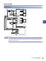
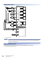
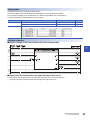
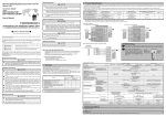
Using terminal block converter module and dedicated cables
The temperature control module measures temperatures based on the temperature of the terminal block. Thus, depending on
the system configuration used, the temperature distribution of the terminal block is not uniform due to the effects of heat
generated from modules, and the measured temperature may greatly differ from the actual temperature. (especially when two
or more temperature control modules are connected next to each other or the temperature control module is mounted next to
the power supply module or CPU module).
In such cases, using the following terminal block converter module and dedicated cables reduces an error caused by the heat
generated.
Temperature control module
5
Temperature control dedicated cable
with Q terminal block
Remove the provided terminal block, and install
the terminal block of the dedicated cable instead.
Terminal block converter module
for temperature control
Thermocouple or compensation conductor
Item
Model
Manufacturer
Temperature control dedicated cable with Q
terminal block
FA-CBLQ64TC** (**: Cable length)
Your local Mitsubishi Electric sales office or
representative
Terminal block converter module for temperature
control
FA-TB20TC
5 SYSTEM CONFIGURATION
5.1 Precautions for System Configuration
27
6
INSTALLATION AND WIRING
This chapter describes the installation and wiring of the temperature control module.
6.1
Terminal Block
Precautions
Tighten the terminal block screws within the following specified tightening torque range.
Undertightening can cause drop of the screw, short circuit, or malfunction. Overtightening can damage the screw and/or
module, resulting in drop, short circuit, or malfunction.
Screw
Tightening torque range
Terminal screw (M3 screw)
0.42 to 0.58Nm
Terminal block mounting screw (M3.5 screw)
0.66 to 0.89Nm
The following table shows the applicable solderless terminal installed to the terminal block. For wiring, use the wire applicable
to the following wire and mount with the applicable tightening torque. Use a UL-approved solderless terminal and tools
recommended by the manufacturer of the solderless terminal. The solderless terminal with an insulation sleeve cannot be
used.
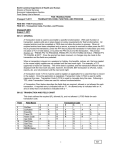
Solderless terminal
28
Wire
Model
Applicable
tightening torque
Wire diameter
Type
Material
Temperature rating
R1.25-3
0.42 to 0.58Nm
22 to 18 AWG
Stranded wire
Copper wire
75
6 INSTALLATION AND WIRING
6.1 Terminal Block
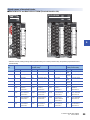
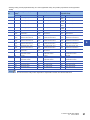
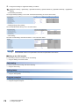
Signal names of terminal blocks
■R60TCTRT2TT2 and R60TCTRT2TT2BW (Terminal block for I/O)
6
• Standard control, heating-cooling control (normal mode), mix control (normal mode), and position proportional control
(normal mode)
Terminal
No.
Standard control
Heating-cooling control
(normal mode)
Mix control (normal mode)
Position proportional
control (normal mode)
Symbol
Name
Symbol
Name
Symbol
Name
Symbol
Name
1
L1
CH1 Output
L1H
CH1 Heating output
L1H
CH1 Heating output
CH1
OPEN
CH1 Open output
2
L2
CH2 Output
L1C
CH1 Cooling output
L1C
CH1 Cooling output
CH1
CLOSE
CH1 Close output
3
L3
CH3 Output
L2H
CH2 Heating output
L3
CH3 Output
CH2
OPEN
CH2 Open output
4
L4
CH4 Output
L2C
CH2 Cooling output
L4
CH4 Output
CH2
CLOSE
CH2 Close output
5
COM-
Output common
COM-
Output common
COM-
Output common
COM-
Output common
6
NC/
CH2A
Not used/CH2
Resistance
thermometer A
NC/
CH2A
Not used/CH2
Resistance
thermometer A
NC/
MT2A
Not used/Monitor
resistance
thermometer A
NC/
CH2A
Not used/CH2
Resistance
thermometer A
7
CH1+/
CH1B
CH1 Thermocouple
+/CH1 Resistance
thermometer B
CH1+/
CH1B
CH1 Thermocouple
+/CH1 Resistance
thermometer B
CH1+/
CH1B
CH1 Thermocouple
+/CH1 Resistance
thermometer B
CH1+/
CH1B
CH1 Thermocouple
+/CH1 Resistance
thermometer B
8
CH2+/
CH2B
CH2 Thermocouple
+/CH2 Resistance
thermometer B
CH2+/
CH2B
CH2 Thermocouple
+/CH2 Resistance
thermometer B
MT2+/
MT2B
Monitor 2
thermocouple +/
Monitor resistance
thermometer B
CH2+/
CH2B
CH2 Thermocouple
+/CH2 Resistance
thermometer B
9
CH1-/
CH1b
CH1 Thermocouple -/
CH1 Resistance
thermometer b
CH1-/
CH1b
CH1 Thermocouple -/
CH1 Resistance
thermometer b
CH1-/
CH1b
CH1 Thermocouple -/
CH1 Resistance
thermometer b
CH1-/
CH1b
CH1 Thermocouple -/
CH1 Resistance
thermometer b
6 INSTALLATION AND WIRING
6.1 Terminal Block
29
30
Terminal
No.
Standard control
Symbol
Name
Symbol
Name
Symbol
Name
Symbol
Name
10
CH2-/
CH2b
CH2 Thermocouple -/
CH2 Resistance
thermometer b
CH2-/
CH2b
CH2 Thermocouple -/
CH2 Resistance
thermometer b
MT2-/
MT2b
Monitor 2
thermocouple-/
Monitor resistance
thermometer b
CH2-/
CH2b
CH2 Thermocouple -/
CH2 Resistance
thermometer b
11
NC/
CH1A
Not used/CH1
Resistance
thermometer A
NC/
CH1A
Not used/CH1
Resistance
thermometer A
NC/
CH1A
Not used/CH1
Resistance
thermometer A
NC/
CH1A
Not used/CH1
Resistance
thermometer A
12
CJ
Cold junction
temperature
compensation
resistor
CJ
Cold junction
temperature
compensation
resistor
CJ
Cold junction
temperature
compensation
resistor
CJ
Cold junction
temperature
compensation
resistor
13
NC
Not used
NC
Not used
NC
Not used
NC
Not used
14
CJ
Cold junction
temperature
compensation
resistor
CJ
Cold junction
temperature
compensation
resistor
CJ
Cold junction
temperature
compensation
resistor
CJ
Cold junction
temperature
compensation
resistor
15
CH3+
CH3 Thermocouple +
MT3+
Monitor 3
thermocouple +
CH3+
CH3 Thermocouple +
MT3+
Monitor 3
thermocouple +
16
CH4+
CH4 Thermocouple +
MT4+
Monitor 4
thermocouple +
CH4+
CH4 Thermocouple +
MT4+
Monitor 4
thermocouple +
17
CH3-
CH3 Thermocouple -
MT3-
Monitor 3
thermocouple -
CH3-
CH3 Thermocouple -
MT3-
Monitor 3
thermocouple -
18
CH4-
CH4 Thermocouple -
MT4-
Monitor 4
thermocouple -
CH4-
CH4 Thermocouple -
MT4-
Monitor 4
thermocouple -
6 INSTALLATION AND WIRING
6.1 Terminal Block
Heating-cooling control
(normal mode)
Mix control (normal mode)
Position proportional
control (normal mode)
• Heating-cooling control (expanded mode), mix control (expanded mode), and position proportional control (expanded
mode)
Terminal
No.
Heating-cooling control (expanded
mode)
Mix control (expanded mode)
Position proportional control
(expanded mode)
Symbol
Name
Symbol
Name
Symbol
Name
1
L1H
CH1 Heating output
L1H
CH1 Heating output
CH1
OPEN
CH1 Open output
2
L1C
CH1 Cooling output
L1C
CH1 Cooling output
CH1
CLOSE
CH1 Close output
3
L2H
CH2 Heating output
L3
CH3 Output
CH2
OPEN
CH2 Open output
4
L2C
CH2 Cooling output
L4
CH4 Output
CH2
CLOSE
CH2 Close output
5
COM-
Output common
COM-
Output common
COM-
Output common
6
NC/
CH2A
Not used/CH2 Resistance
thermometer A
NC/
CH2A
Not used/CH2 Resistance
thermometer A
NC/
CH2A
Not used/CH2 Resistance
thermometer A
7
CH1+/
CH1B
CH1 Thermocouple +/CH1
Resistance thermometer B
CH1+/
CH1B
CH1 Thermocouple +/CH1
Resistance thermometer B
CH1+/
CH1B
CH1 Thermocouple +/CH1
Resistance thermometer B
8
CH2+/
CH2B
CH2 Thermocouple +/CH2
Resistance thermometer B
CH2+/
CH2B
CH2 Thermocouple +/CH2
Resistance thermometer B
CH2+/
CH2B
CH2 Thermocouple +/CH2
Resistance thermometer B
9
CH1-/
CH1b
CH1 Thermocouple -/CH1
Resistance thermometer b
CH1-/
CH1b
CH1 Thermocouple -/CH1
Resistance thermometer b
CH1-/
CH1b
CH1 Thermocouple -/CH1
Resistance thermometer b
10
CH2-/
CH2b
CH2 Thermocouple -/CH2
Resistance thermometer b
CH2-/
CH2b
CH2 Thermocouple -/CH2
Resistance thermometer b
CH2-/
CH2b
CH2 Thermocouple -/CH2
Resistance thermometer b
11
NC/
CH1A
Not used/CH1 Resistance
thermometer A
NC/
CH1A
Not used/CH1 Resistance
thermometer A
NC
Not used
12
CJ
Cold junction temperature
compensation resistor
CJ
Cold junction temperature
compensation resistor
CJ
Cold junction temperature
compensation resistor
13
NC
Not used
NC
Not used
NC
Not used
14
CJ
Cold junction temperature
compensation resistor
CJ
Cold junction temperature
compensation resistor
CJ
Cold junction temperature
compensation resistor
15
CH3+
CH3 Thermocouple +
CH3+
CH3 Thermocouple +
CH3+
CH3 Thermocouple +
16
CH4+
CH4 Thermocouple +
CH4+
CH4 Thermocouple +
CH4+
CH4 Thermocouple +
17
CH3-
CH3 Thermocouple -
CH3-
CH3 Thermocouple -
CH3-
CH3 Thermocouple -
18
CH4-
CH4 Thermocouple -
CH4-
CH4 Thermocouple -
CH4-
CH4 Thermocouple -
6
Do not remove the cold junction temperature compensation resistor from the terminal block.
6 INSTALLATION AND WIRING
6.1 Terminal Block
31
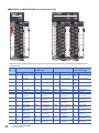
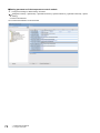
■R60TCRT4 and R60TCRT4BW (Terminal block for I/O)
• Standard control, heating-cooling control (normal mode), mix control (normal mode), and position proportional control
(normal mode)
Terminal
No.
32
Standard control
Heating-cooling control
(normal mode)
Mix control (normal mode)
Position proportional
control (normal mode)
Symbol
Name
Symbol
Name
Symbol
Name
Symbol
Name
1
L1
CH1 Output
L1H
CH1 Heating output
L1H
CH1 Heating output
CH1
OPEN
CH1 Open output
2
L2
CH2 Output
L1C
CH1 Cooling output
L1C
CH1 Cooling output
CH1
CLOSE
CH1 Close output
3
L3
CH3 Output
L2H
CH2 Heating output
L3
CH3 Output
CH2
OPEN
CH2 Open output
4
L4
CH4 Output
L2C
CH2 Cooling output
L4
CH4 Output
CH2
CLOSE
CH2 Close output
5
COM-
Output common
COM-
Output common
COM-
Output common
COM-
Output common
6
NC
Not used
NC
Not used
NC
Not used
NC
Not used
7
CH1A
CH1 Resistance
thermometer A
CH1A
CH1 Resistance
thermometer A
CH1A
CH1 Resistance
thermometer A
CH1A
CH1 Resistance
thermometer A
8
CH2A
CH2 Resistance
thermometer A
CH2A
CH2 Resistance
thermometer A
MT2A
Monitor 2 resistance
thermometer A
CH2A
CH2 Resistance
thermometer A
9
CH1B
CH1 Resistance
thermometer B
CH1B
CH1 Resistance
thermometer B
CH1B
CH1 Resistance
thermometer B
CH1B
CH1 Resistance
thermometer B
10
CH2B
CH2 Resistance
thermometer B
CH2B
CH2 Resistance
thermometer B
MT2B
Monitor 2 resistance
thermometer B
CH2B
CH2 Resistance
thermometer B
11
CH1b
CH1 Resistance
thermometer b
CH1b
CH1 Resistance
thermometer b
CH1b
CH1 Resistance
thermometer b
CH1b
CH1 Resistance
thermometer b
12
CH2b
CH2 Resistance
thermometer b
CH2b
CH2 Resistance
thermometer b
MT2b
Monitor 2 resistance
thermometer b
CH2b
CH2 Resistance
thermometer b
13
CH3A
CH3 Resistance
thermometer A
MT3A
Monitor 3 resistance
thermometer A
CH3A
CH3 Resistance
thermometer A
MT3A
Monitor 3 resistance
thermometer A
14
CH4A
CH4 Resistance
thermometer A
MT4A
Monitor 4 resistance
thermometer A
CH4A
CH4 Resistance
thermometer A
MT4A
Monitor 4 resistance
thermometer A
6 INSTALLATION AND WIRING
6.1 Terminal Block
Terminal
No.
Standard control
Heating-cooling control
(normal mode)
Mix control (normal mode)
Position proportional
control (normal mode)
Symbol
15
CH3B
Name
Symbol
Name
Symbol
Name
Symbol
Name
CH3 Resistance
thermometer B
MT3B
Monitor 3 resistance
thermometer B
CH3B
CH3 Resistance
thermometer B
MT3B
Monitor 3 resistance
thermometer B
16
CH4B
CH4 Resistance
thermometer B
MT4B
Monitor 4 resistance
thermometer B
CH4B
CH4 Resistance
thermometer B
MT4B
Monitor 4 resistance
thermometer B
17
CH3b
CH3 Resistance
thermometer b
MT3b
Monitor 3 resistance
thermometer b
CH3b
CH3 Resistance
thermometer b
MT3b
Monitor 3 resistance
thermometer b
18
CH4b
CH4 Resistance
thermometer b
MT4b
Monitor 4 resistance
thermometer b
CH4b
CH4 Resistance
thermometer b
MT4b
Monitor 4 resistance
thermometer b
6
6 INSTALLATION AND WIRING
6.1 Terminal Block
33
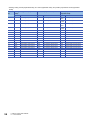
• Heating-cooling control (expanded mode), mix control (expanded mode), and position proportional control (expanded
mode)
34
Terminal
No.
Heating-cooling control (expanded
mode)
Mix control (expanded mode)
Position proportional control
(expanded mode)
Symbol
Name
Symbol
Name
Symbol
Name
1
L1H
CH1 Heating output
L1H
CH1 Heating output
CH1
OPEN
CH1 Open output
2
L1C
CH1 Cooling output
L1C
CH1 Cooling output
CH1
CLOSE
CH1 Close output
3
L2H
CH2 Heating output
L3
CH3 Output
CH2
OPEN
CH2 Open output
4
L2C
CH2 Cooling output
L4
CH4 Output
CH2
CLOSE
CH2 Close output
5
COM-
Output common
COM-
Output common
COM-
Output common
6
NC
Not used
NC
Not used
NC
Not used
7
CH1A
CH1 Resistance thermometer A
CH1A
CH1 Resistance thermometer A
CH1A
CH1 Resistance thermometer A
8
CH2A
CH2 Resistance thermometer A
CH2A
CH2 Resistance thermometer A
CH2A
CH2 Resistance thermometer A
9
CH1B
CH1 Resistance thermometer B
CH1B
CH1 Resistance thermometer B
CH1B
CH1 Resistance thermometer B
10
CH2B
CH2 Resistance thermometer B
CH2B
CH2 Resistance thermometer B
CH2B
CH2 Resistance thermometer B
11
CH1b
CH1 Resistance thermometer b
CH1b
CH1 Resistance thermometer b
CH1b
CH1 Resistance thermometer b
12
CH2b
CH2 Resistance thermometer b
CH2b
CH2 Resistance thermometer b
CH2b
CH2 Resistance thermometer b
13
CH3A
CH3 Resistance thermometer A
CH3A
CH3 Resistance thermometer A
CH3A
CH3 Resistance thermometer A
14
CH4A
CH4 Resistance thermometer A
CH4A
CH4 Resistance thermometer A
CH4A
CH4 Resistance thermometer A
15
CH3B
CH3 Resistance thermometer B
CH3B
CH3 Resistance thermometer B
CH3B
CH3 Resistance thermometer B
16
CH4B
CH4 Resistance thermometer B
CH4B
CH4 Resistance thermometer B
CH4B
CH4 Resistance thermometer B
17
CH3b
CH3 Resistance thermometer b
CH3b
CH3 Resistance thermometer b
CH3b
CH3 Resistance thermometer b
18
CH4b
CH4 Resistance thermometer b
CH4b
CH4 Resistance thermometer b
CH4b
CH4 Resistance thermometer b
6 INSTALLATION AND WIRING
6.1 Terminal Block
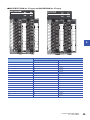
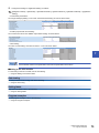
■R60TCTRT2TT2BW (for CT input) and R60TCRT4BW (for CT input)
6
Terminal No.
Standard control and heating-cooling control
Symbol
Name
1
NC
Not used
2
CT1
CT input 1
3
CT1
CT input 1
4
CT2
CT input 2
5
CT2
CT input 2
6
CT3
CT input 3
7
CT3
CT input 3
8
CT4
CT input 4
9
CT4
CT input 4
10
CT5
CT input 5
11
CT5
CT input 5
12
CT6
CT input 6
13
CT6
CT input 6
14
CT7
CT input 7
15
CT7
CT input 7
16
CT8
CT input 8
17
CT8
CT input 8
18
NC
Not used
6 INSTALLATION AND WIRING
6.1 Terminal Block
35
6.2
Wiring Precautions
External wiring that is less likely to be affected by noise is one of the conditions for a highly reliable system that fully utilizes
the temperature control module.
This section describes wiring precautions.
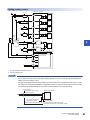
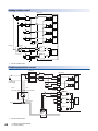
• Use separate cables for the AC control circuit and the temperature control module's external I/O signals to avoid influence
of AC side surges and induction.
• Do not locate external wires near the main circuit line, high-voltage circuit lines, and load circuit lines of devices other than
programmable controllers such as an inverter. Also, do not bunch external wires with these lines. Otherwise, the external
wires are more likely to be affected by noise, surges, and induction.
• Ground shielded cables at one end on the programmable controller side. However, depending on the external noise
condition, it should be grounded on the other side.
• To ensure that this product maintains EMC and Low Voltage Directives, refer to the following.
MELSEC iQ-R Module Configuration Manual
Safety Guidelines (This manual is included with the base unit.)
36
6 INSTALLATION AND WIRING
6.2 Wiring Precautions
6.3
External Wiring
The following figure shows the external wiring.
R60TCTRT2TT2
Standard control
R60TCTRT2TT2
*2
Internal
circuit
L1
L2
·
·
*2
L4
Internal
circuit
COM24VDC
*1
Controlled
object
·
CH1+
CH1-
Filter
CH2+
CH2-
Filter
6
Internal
circuit
*1
CH4+
CH4-
*1
*2
Filter
Use the shielded compensation lead wire.
Use the shielded cable.
Use the compensation lead wire for the cable of a thermocouple. If the compensation lead wire is not used,
and when the cold junction temperature compensation resistor is away from the end tip of a thermocouple, the
(ambient) temperature difference may lead to a faulty temperature process value (PV).
Reference junction
R60TCTRT2TT2(BW)
Compensation lead wire (OK)
Shielded cable (NG)
A
Cold junction temperature
compensation resistor
(Ambient) temperature difference
Terminal block
B
A: Reference junction of the thermocouple
B: Cold junction temperature compensation resistor
6 INSTALLATION AND WIRING
6.3 External Wiring
37
Heating-cooling control
R60TCTRT2TT2
*2
L1H
Internal
circuit
L1C
Internal
circuit
L2H
Internal
circuit
L2C
Internal
circuit
*2
*2
*2
COM-
Heating
24VDC
Cooling
Controlled
object
*1
CH1+
CH1-
Filter
Internal
circuit
*1
CH2+
CH2-
*1
*2
Filter
Use the shielded compensation lead wire.
Use the shielded cable.
Use the compensation lead wire for the cable of a thermocouple. If the compensation lead wire is not used,
and when the cold junction temperature compensation resistor is away from the end tip of a thermocouple, the
(ambient) temperature difference may lead to a faulty temperature process value (PV).
Reference junction
R60TCTRT2TT2(BW)
Compensation lead wire (OK)
Shielded cable (NG)
A
Cold junction temperature
compensation resistor
(Ambient) temperature difference
Terminal block
B
A: Reference junction of the thermocouple
B: Cold junction temperature compensation resistor
38
6 INSTALLATION AND WIRING
6.3 External Wiring
Position proportional control
Positioner
*2
R60TCTRT2TT2
SSR
*2
Internal
circuit
CH1
OPEN
SSR
CH1
CLOSE
CH2
OPEN
Control motor
power supply
·
Internal
circuit
CH2
CLOSE
COMOUT1
(CH1 open side)
OUT2
(CH1 close side)
24VDC
*1
CH1+
Filter
CH1*1
CH2+
M
Internal
circuit
Filter
CH2Control motor
Fluid
CH4+
Controlled
object
Filter
6
CH4-
Controlled
object
*1
*2
Use the shielded compensation lead wire.
Use the shielded cable.
Use the compensation lead wire for the cable of a thermocouple. If the compensation lead wire is not used,
and when the cold junction temperature compensation resistor is away from the end tip of a thermocouple, the
(ambient) temperature difference may lead to a faulty temperature process value (PV).
Reference junction
R60TCTRT2TT2(BW)
Compensation lead wire (OK)
Shielded cable (NG)
A
Cold junction temperature
compensation resistor
(Ambient) temperature difference
Terminal block
B
A: Reference junction of the thermocouple
B: Cold junction temperature compensation resistor
6 INSTALLATION AND WIRING
6.3 External Wiring
39
R60TCTRT2TT2BW
Standard control
R60TCTRT2TT2BW
*2
Internal
circuit
L1
L2
·
·
*2
Internal
circuit
L4
COM-
Current sensor
(CT)
*1
24VDC
Controlled
object
·
CH1+
CH1-
Filter
CH2+
CH2-
Filter
CH4+
CH4-
Filter
Internal
circuit
*1
Connector
Connector
*2
CT1
CT1
CT input circuit
CT2
CT2
CT8
CT8
*1
*2
Use the shielded compensation lead wire.
Use the shielded cable.
• To use the heater disconnection detection function, the CT input channel assignment must be set. Since the
CT1 is used in the loop of CH1 in the above wiring example, set "CH1" for "CT input channel assignment
setting" in the "CT setting" of CT1.
• Use the compensation lead wire for the cable of a thermocouple. If the compensation lead wire is not used,
and when the cold junction temperature compensation resistor is away from the end tip of a thermocouple,
the (ambient) temperature difference may lead to a faulty temperature process value (PV).
Reference junction
R60TCTRT2TT2(BW)
Compensation lead wire (OK)
Shielded cable (NG)
A
Cold junction temperature
compensation resistor
(Ambient) temperature difference
Terminal block
B
A: Reference junction of the thermocouple
B: Cold junction temperature compensation resistor
40
6 INSTALLATION AND WIRING
6.3 External Wiring
Heating-cooling control
R60TCTRT2TT2BW
*2
L1H
Internal
circuit
L1C
Internal
circuit
L2H
Internal
circuit
L2C
Internal
circuit
*2
*2
*2
Current
sensor
(CT)
Cooling
Controlled
object
COM-
24VDC
*1
CH1+
CH1-
Heating
6
Filter
Internal
circuit
*1
CH2+
CH2-
Filter
Connector
Connector
*2
CT1
CT1
CT input circuit
CT2
CT2
CT8
CT8
*1
*2
Use the shielded compensation lead wire.
Use the shielded cable.
• To use the heater disconnection detection function, the CT input channel assignment must be set. Since the
CT1 is used in the loop of CH1 in the above wiring example, set "CH1" for "CT input channel assignment
setting" in the "CT setting" of CT1.
• Use the compensation lead wire for the cable of a thermocouple. If the compensation lead wire is not used,
and when the cold junction temperature compensation resistor is away from the end tip of a thermocouple,
the (ambient) temperature difference may lead to a faulty temperature process value (PV).
Reference junction
R60TCTRT2TT2(BW)
Compensation lead wire (OK)
Shielded cable (NG)
A
Cold junction temperature
compensation resistor
(Ambient) temperature difference
Terminal block
B
A: Reference junction of the thermocouple
B: Cold junction temperature compensation resistor
6 INSTALLATION AND WIRING
6.3 External Wiring
41
Position proportional control
The CT input is invalid in the position proportional control. For wiring examples, refer to the following.
Page 39 Position proportional control
42
6 INSTALLATION AND WIRING
6.3 External Wiring
R60TCRT4
Standard control
R60TCRT4
*1
Internal
circuit
L1
L2
·
·
*1
Internal
circuit
L4
COM-
*1
24VDC
A
B
b
CH1 A
CH1 B
CH1 b
Controlled
object
·
*1
CH2 A
CH2 B
CH2 b
CH4 A
CH4 B
CH4 b
*1
Filter
Filter
Internal
circuit
6
Filter
Use the shielded cable.
6 INSTALLATION AND WIRING
6.3 External Wiring
43
Heating-cooling control
R60TCRT4
*1
L1H
Internal
circuit
L1C
Internal
circuit
L2H
Internal
circuit
L2C
Internal
circuit
*1
*1
*1
COM-
24VDC
Heating
Cooling
A
A
B
bb
*1
Filter
CH1 A
CH1 B
CH1 b
Controlled
object
Internal
circuit
*1
Filter
CH2 A
CH2 B
CH2 b
*1
Use the shielded cable.
Position proportional control
Positioner
*1
R60TCRT4
SSR
*1
Internal
circuit
CH1
OPEN
SSR
CH1
CLOSE
CH2
OPEN
Control motor
power supply
·
Internal
circuit
CH2
CLOSE
COM-
OUT1
(CH1 open side)
OUT2
(CH1 close side)
24VDC
*1
CH1 A
Filter
CH1 B
CH1 b
M
CH2 A
Control motor
Filter
CH2 B
Fluid
CH1 b
CH4 A
A B b
CH4 B
CH4 b
Controlled
object
*1
44
Use the shielded cable.
6 INSTALLATION AND WIRING
6.3 External Wiring
Filter
Internal
circuit
R60TCRT4BW
Standard control
R60TCRT4BW
*1
Internal
circuit
L1
L2
·
·
*1
Internal
circuit
L4
Current sensor
(CT)
COM-
*1
A
B
b
24VDC
CH1 A
CH1 B
CH1 b
Controlled
object
·
*1
CH2 A
CH2 B
CH2 b
CH4 A
CH4 B
CH4 b
Filter
Filter
Internal
circuit
6
Filter
Connector
Connector
*1
CT1
CT1
CT input circuit
CT2
CT2
CT8
CT8
*1
Use the shielded cable.
To use the heater disconnection detection function, the CT input channel assignment must be set. Since the
CT1 is used in the loop of CH1 in the above wiring example, set "CH1" for "CT input channel assignment
setting" in the "CT setting" of CT1.
6 INSTALLATION AND WIRING
6.3 External Wiring
45
Heating-cooling control
R60TCRT4BW
*1
L1H
Internal
circuit
L1C
Internal
circuit
L2H
Internal
circuit
L2C
Internal
circuit
*1
*1
*1
Current
sensor
Cooling
(CT)
A
B
b
Heating
Controlled
objectd
COM-
24VDC
*1
CH1 A
CH1 B
CH1 b
Filter
CH2 A
CH2 B
CH2 b
Filter
Internal
circuit
*1
Connector
Connector
*1
CT1
CT1
CT input circuit
CT2
CT2
CT8
CT8
*1
Use the shielded cable.
To use the heater disconnection detection function, the CT input channel assignment must be set. Since the
CT1 is used in the loop of CH1 in the above wiring example, set "CH1" for "CT input channel assignment
setting" in the "CT setting" of CT1.
Position proportional control
The CT input is invalid in the position proportional control. For wiring examples, refer to the following.
Page 44 Position proportional control
46
6 INSTALLATION AND WIRING
6.3 External Wiring
6.4
Heater Disconnection Detection Wiring and
Setting Example for Three-phase Heater
The following shows the wiring and setting examples to detect a disconnection of a three-phase heater with the heater
disconnection detection function.
R60TCTRT2TT2BW
R60TCRT4BW
L1
L2
L3
L4
COM-
CH1
Controlled
object
CH2
6
CH3
CH4
CT1
CT1
CT2
CT2
CT3
To three-phase heater (used in CH2 loop)
CT3
CT4
CT4
To single-phase heater (used in CH3 loop)
CT5
CT5
To single-phase heater (used in CH4 loop)
CT6
CT6
CT7
Unused
CT7
CT8
CT8
The disconnection of the three-phase heater is detected by measuring the currents of two of the three cables.
In the above wiring example, set "CT input channel assignment setting" of "CT setting" as indicated below.
Item
Setting value
CT1
CH1 (1)
CT2
CH1 (1)
CT3
CH2 (2)
CT4
CH2 (2)
CT5
CH3(3)
CT6
CH4(4)
CT7
Unused (0)
CT8
Unused (0)
6 INSTALLATION AND WIRING
6.4 Heater Disconnection Detection Wiring and Setting Example for Three-phase Heater
47
6.5
Unused Channel Setting
When no temperature sensor is connected to a channel, the temperature control module performs upscale processing for the
channel. Therefore, when no temperature sensor has not been connected to a channel where no temperature control is to be
performed, the module determines that the temperature process value (PV) has exceeded the temperature measuring range
for the input range, and the ALM LED blinks.
Setting unused channels can prevent faulty alert detection because the PID control, temperature judgment, and alert
judgment are not executed on the set channels.
Setting method
Set a value in "Unused channel setting" of "Control basic parameters" of "Application Setting". The following table shows the
relation between each setting value and control status.
Setting value
Control status
Used (0)
Performed (However, it depends on other setting status.)
Unused (1)
Not performed
PID control
Temperature judgment
Setting unused channels does not change the sampling cycle.
48
6 INSTALLATION AND WIRING
6.5 Unused Channel Setting
Alert judgment
7
OPERATION EXAMPLES
This chapter describes the programming procedure and basic program of the temperature control module.
7.1
Programming Procedure
Create a program that operates the temperature control module using the following procedure.
1.
2.
Set parameters.
Create a program.
Using function blocks (FBs) can reduce the load at programming and improve the readability of a program.
For details on the function blocks, refer to the following.
MELSEC iQ-R Temperature Control Module Function Block Reference
7.2
Program Examples
Standard control
7
System configuration
The following shows a system configuration example.
(1)
(1)
(2)
(3)
(4)
(2)
(3)
(4)
Power supply module (R61P)
CPU module (R120CPU)
Temperature control module (R60TCTRT2TT2)
Input module (RX10)
7 OPERATION EXAMPLES
7.1 Programming Procedure
49
Parameter settings
Connect an engineering tool to the CPU module and set parameters.
In these program examples, use the default setting for the parameters other than the set parameters. For
parameters, refer to the following.
MELSEC iQ-R Temperature Control Module User's Manual (Application)
■Setting modules
1.
Set the CPU module as follows.
[Project] [New]
2.
Click the [Yes] button and add labels of the CPU module.
3.
Set the R60TCTRT2TT2 as follows.
[Navigation window] [Parameter] [Module Information] Right-click [Add New Module]
50
7 OPERATION EXAMPLES
7.2 Program Examples
4.
Click the [Yes] button and add labels of the R60TCTRT2TT2.
■Setting parameters of the temperature control module
1.
Configure the settings in "Base Setting" as follows.
[Navigation window] [Parameter] [Module Information] [R60TCTRT2TT2] [Module Parameter] [Base
Setting]
7
7 OPERATION EXAMPLES
7.2 Program Examples
51
2.
Configure the settings in "Application Setting" as follows.
[Navigation window] [Parameter] [Module Information] [R60TCTRT2TT2] [Module Parameter] [Application
Setting]
• "Control basic parameters"
Set "Target Value(SV) Setting" of CH1 and "Unused channel setting" of CH2 to CH4 as shown below.
• "Limiter setting"
Set "Upper Limit Setting Limiter" of CH1 as shown below.
• "Alert setting"
Set "Alert 1 mode setting" and "Alert set value 1" of CH1 as shown below.
• "Auto tuning setting"
Set "Automatic backup setting after auto tuning of PID constants" of CH1 as shown below.
Use the default values for the parameters other than the parameters shown above.
■Writing to the CPU module
1.
Write the set parameters to the CPU module, reset the CPU module, and turn off and on the power supply.
[Online] [Write to PLC]
52
7 OPERATION EXAMPLES
7.2 Program Examples
Auto tuning
Perform auto tuning.
[Tool] [Module Tool List]
1.
Select "Temperature trace" of "Temperature
Control Module" and click the [OK] button.
2.
7
Select the module to configure the temperature
control setting and click the [OK] button.
3.
Select "Monitor data write" from the following.
[Setting] [Monitor data write]
4.
Set "Setting/Operation mode command" to
"1:Operation mode command".
5.
6.
Set "Auto tuning command" to "1:ON".
Then, "Auto tuning status" is set to "Executing",
and auto tuning is started.
7.
When auto tuning is completed, "Auto tuning
status" is set to "Stopped".
8.
Temperature control is performed by set PID
constants.
7 OPERATION EXAMPLES
7.2 Program Examples
53
Setting labels
GX Works3 has functions supporting program creation.
The following table lists the module labels and global labels used in these program examples.
Do not change the settings of the module labels. For details on global labels, refer to the following.
MELSEC iQ-R Programming Manual (Program Design)
Classification
Label name
Description
Device
Module label
R60TC_1.bModuleREADY
Module READY flag
X0
R60TC_1.bSettingChangeCommand
Setting change command
YB
R60TC_1.bSettingOperationModeCommand
Setting/operation mode command
Y1
R60TC_1.stMonitor.uTemperatureConversionCompletionFlag.0
CH1 Temperature conversion
completion flag
R60TC_1.stnMonitor_Ch[0].wTemperatureProcessValue
CH1 Temperature process value
(PV)
R60TC_1.stnMonitor_Ch[0].uAlertDefinition.8
CH1 Alert definition
Label to be defined
Define global labels as follows.
• Program that changes the setting/operation mode
• Program that processes data when the upper limit input alert occurs
• Program that displays and clears an error code
54
7 OPERATION EXAMPLES
7.2 Program Examples
Program examples
■Program that changes the setting/operation mode
■Program that processes data when the upper limit input alert occurs
■Program that displays and clears an error code
7
7 OPERATION EXAMPLES
7.2 Program Examples
55
Standard control (When using the inter-module simultaneous
temperature rise function)
System configuration
The following shows a system configuration example.
(1)
(1)
(2)
(3)
(4)
(5)
(2)
(3)
(4)
(5)
Power supply module (R61P)
CPU module (R120CPU)
Temperature control module 1 (R60TCTRT2TT2)
Temperature control module 2 (R60TCTRT2TT2)
Input module (RX10)
Parameter settings
Connect an engineering tool to the CPU module and set parameters.
In these program examples, use the default setting for the parameters other than the set parameters. For
parameters, refer to the following.
MELSEC iQ-R Temperature Control Module User's Manual (Application)
■Setting modules
For how to set the module, refer to the following.
Page 50 Setting modules
56
7 OPERATION EXAMPLES
7.2 Program Examples
■Setting parameters of the temperature control module 1
1.
Configure the settings in "Base Setting" as follows.
[Navigation window] [Parameter] [Module Information] [R60TCTRT2TT2] [Module Parameter] [Base
Setting]
• "Multiple module interaction function"
Set "Simultaneous temperature rise function enable/disable between multiple module" and "Simultaneous temperature rise
function master/slave selection between multiple module" as shown below.
7
7 OPERATION EXAMPLES
7.2 Program Examples
57
2.
Configure the settings in "Application Setting" as follows.
[Navigation window] [Parameter] [Module Information] [R60TCTRT2TT2] [Module Parameter] [Application
Setting]
• "Control basic parameters"
Set "Target Value(SV) Setting" of CH1 and CH2, and "Unused channel setting" of CH3 and CH4 as shown below.
• "Limiter setting"
Set "Upper Limit Setting Limiter" of CH1 and CH2 as shown below.
• "Simultaneous temperature rise setting"
Set "Simultaneous temperature rise group setting" and "Simultaneous temperature rise AT mode setting" of CH1 and CH2 as
shown below.
• "Alert setting"
Set "Alert 1 mode setting" and "Alert set value 1" of CH1 and CH2 as shown below.
• "Auto tuning setting"
Set "Automatic backup setting after auto tuning of PID constants" of CH1 and CH2 as shown below.
Use the default values for the parameters other than the parameters shown above.
58
7 OPERATION EXAMPLES
7.2 Program Examples
■Setting parameters of the temperature control module 2
1.
Configure the settings in "Base Setting" as follows.
[Navigation window] [Parameter] [Module Information] [R60TCTRT2TT2] [Module Parameter] [Base
Setting]
• "Multiple module interaction function"
Set "Simultaneous temperature rise function enable/disable between multiple module" as shown below.
7
7 OPERATION EXAMPLES
7.2 Program Examples
59
2.
Configure the settings in "Application Setting" as follows.
[Navigation window] [Parameter] [Module Information] [R60TCTRT2TT2] [Module Parameter] [Application
Setting]
• "Control basic parameters"
Set "Target Value(SV) Setting" of CH1 and CH2, and "Unused channel setting" of CH3 and CH4 as shown below.
• "Limiter setting"
Set "Upper Limit Setting Limiter" of CH1 and CH2 as shown below.
• "Simultaneous temperature rise setting"
Set "Simultaneous temperature rise group setting" and "Simultaneous temperature rise AT mode setting" of CH1 and CH2 as
shown below.
• "Alert setting"
Set "Alert 1 mode setting" and "Alert set value 1" of CH1 and CH2 as shown below.
• "Auto tuning setting"
Set "Automatic backup setting after auto tuning of PID constants" of CH1 and CH2 as shown below.
Use the default values for the parameters other than the parameters shown above.
■Writing to the CPU module
For the writing to the CPU module, refer to the following.
Page 52 Writing to the CPU module
Auto tuning
For the procedure of auto tuning, refer to the following.
Page 53 Auto tuning
60
7 OPERATION EXAMPLES
7.2 Program Examples
Setting labels
GX Works3 has functions supporting program creation.
The following table lists the module labels and global labels used in these program examples.
Do not change the settings of the module labels. For details on global labels, refer to the following.
MELSEC iQ-R Programming Manual (Program Design)
Classification
Label name
Description
Device
Module label
R60TC_1.bModuleREADY
Module READY flag
X0
R60TC_2.bModuleREADY
Module READY flag
X10
Label to be defined
Define global labels as follows.
Program examples
■Program example of the inter-module simultaneous temperature rise
7
■Program that is processed when the upper limit input alert occurs
For the program that is processed when the upper limit input alert occurs, refer to the following.
Page 55 Program that processes data when the upper limit input alert occurs
7 OPERATION EXAMPLES
7.2 Program Examples
61
Standard control (When using the inter-module peak current
suppression function)
System configuration
The following shows a system configuration example.
(1)
(1)
(2)
(3)
(4)
(5)
(2)
(3)
(4)
(5)
Power supply module (R61P)
CPU module (R120CPU)
Temperature control module 1 (R60TCTRT2TT2)
Temperature control module 2 (R60TCTRT2TT2)
Input module (RX10)
Parameter settings
Connect an engineering tool to the CPU module and set parameters.
In these program examples, use the default setting for the parameters other than the set parameters. For
parameters, refer to the following.
MELSEC iQ-R Temperature Control Module User's Manual (Application)
■Setting modules
For how to set the module, refer to the following.
Page 50 Setting modules
62
7 OPERATION EXAMPLES
7.2 Program Examples
■Setting parameters of the temperature control module 1
1.
Configure the settings in "Base Setting" as follows.
[Navigation window] [Parameter] [Module Information] [R60TCTRT2TT2] [Module Parameter] [Base
Setting]
• "Multiple module interaction function"
Set "Peak current suppression function enable/disable between multiple module" and "Peak current suppression function
master/slave selection between multiple module" as shown below.
7
7 OPERATION EXAMPLES
7.2 Program Examples
63
2.
Configure the settings in "Application Setting" as follows.
[Navigation window] [Parameter] [Module Information] [R60TCTRT2TT2] [Module Parameter] [Application
Setting]
• "Control basic parameters"
Set "Target Value(SV) Setting" of CH1 and CH2, and "Unused channel setting" of CH3 and CH4 as shown below.
• "Limiter setting"
Set "Upper Limit Setting Limiter" of CH1 and CH2 as shown below.
• "Peak current suppression setting"
Set "Peak current suppression control group setting" of CH1 and CH2 as shown below.
• "Alert setting"
Set "Alert 1 mode setting" and "Alert set value 1" of CH1 and CH2 as shown below.
• "Auto tuning setting"
Set "Automatic backup setting after auto tuning of PID constants" of CH1 and CH2 as shown below.
Use the default values for the parameters other than the parameters shown above.
64
7 OPERATION EXAMPLES
7.2 Program Examples
■Setting parameters of the temperature control module 2
1.
Configure the settings in "Base Setting" as follows.
[Navigation window] [Parameter] [Module Information] [R60TCTRT2TT2] [Module Parameter] [Base
Setting]
• "Multiple module interaction function"
Set "Peak current suppression function enable/disable between multiple module" as shown below.
7
7 OPERATION EXAMPLES
7.2 Program Examples
65
2.
Configure the settings in "Application Setting" as follows.
[Navigation window] [Parameter] [Module Information] [R60TCTRT2TT2] [Module Parameter] [Application
Setting]
• "Control basic parameters"
Set "Target Value(SV) Setting" of CH1 and CH2, and "Unused channel setting" of CH3 and CH4 as shown below.
• "Limiter setting"
Set "Upper Limit Setting Limiter" of CH1 and CH2 as shown below.
• "Peak current suppression setting"
Set "Peak current suppression control group setting" of CH1 and CH2 as shown below.
• "Alert setting"
Set "Alert 1 mode setting" and "Alert set value 1" of CH1 and CH2 as shown below.
• "Auto tuning setting"
Set "Automatic backup setting after auto tuning of PID constants" of CH1 and CH2 as shown below.
Use the default values for the parameters other than the parameters shown above.
■Writing to the CPU module
For the writing to the CPU module, refer to the following.
Page 52 Writing to the CPU module
Auto tuning
For the procedure of auto tuning, refer to the following.
Page 53 Auto tuning
66
7 OPERATION EXAMPLES
7.2 Program Examples
Setting labels
GX Works3 has functions supporting program creation.
The following table lists the module labels and global labels used in these program examples.
Do not change the settings of the module labels. For details on global labels, refer to the following.
MELSEC iQ-R Programming Manual (Program Design)
Classification
Label name
Description
Device
Module label
R60TC_1.bModuleREADY
Module READY flag
X0
R60TC_2.bModuleREADY
Module READY flag
X10
Label to be defined
Define global labels as follows.
Program examples
■Program example of the inter-module peak current suppression
7
■Program that is processed when the upper limit input alert occurs
For the program that is processed when the upper limit input alert occurs, refer to the following.
Page 55 Program that processes data when the upper limit input alert occurs
7 OPERATION EXAMPLES
7.2 Program Examples
67
Heating-cooling control
System configuration
The following shows a system configuration example.
(1)
(1)
(2)
(3)
(4)
(2)
(3)
(4)
Power supply module (R61P)
CPU module (R120CPU)
Temperature control module (R60TCTRT2TT2)
Input module (RX10)
Parameter settings
Connect an engineering tool to the CPU module and set parameters.
In these program examples, use the default setting for the parameters other than the set parameters. For
parameters, refer to the following.
MELSEC iQ-R Temperature Control Module User's Manual (Application)
■Setting modules
For how to set the module, refer to the following.
Page 50 Setting modules
68
7 OPERATION EXAMPLES
7.2 Program Examples
■Setting parameters of the temperature control module
1.
Configure the settings in "Base Setting" as follows.
[Navigation window] [Parameter] [Module Information] [R60TCTRT2TT2] [Module Parameter] [Base
Setting]
• "Control mode selection"
Set "Control mode selection" as shown below.
7
7 OPERATION EXAMPLES
7.2 Program Examples
69
2.
Configure the settings in "Application Setting" as follows.
[Navigation window] [Parameter] [Module Information] [R60TCTRT2TT2] [Module Parameter] [Application
Setting]
• "Control basic parameters"
Set "Target Value(SV) Setting" of CH1 and "Unused channel setting" of CH2 as shown below.
• "Heating/cooling control setting"
Set "Overlap/dead band setting" of CH1 as shown below.
• "Alert setting"
Set "Alert 1 mode setting" and "Alert set value 1" of CH1 as shown below.
Use the default values for the parameters other than the parameters shown above.
■Writing to the CPU module
For the writing to the CPU module, refer to the following.
Page 52 Writing to the CPU module
Auto tuning
For the procedure of auto tuning, refer to the following.
Page 53 Auto tuning
Setting labels
Fort how to set labels, refer to the following.
Page 54 Setting labels
Program examples
For the program examples, refer to the following.
Page 55 Program examples
70
7 OPERATION EXAMPLES
7.2 Program Examples
Position proportional control
System configuration
The following shows a system configuration example.
(1)
(1)
(2)
(3)
(4)
(2)
(3)
(4)
Power supply module (R61P)
CPU module (R120CPU)
Temperature control module (R60TCTRT2TT2)
Input module (RX10)
7
Parameter settings
Connect an engineering tool to the CPU module and set parameters.
In these program examples, use the default setting for the parameters other than the set parameters. For
parameters, refer to the following.
MELSEC iQ-R Temperature Control Module User's Manual (Application)
■Setting modules
For how to set the module, refer to the following.
Page 50 Setting modules
7 OPERATION EXAMPLES
7.2 Program Examples
71
■Setting parameters of the temperature control module
1.
Configure the settings in "Base Setting" as follows.
[Navigation window] [Parameter] [Module Information] [R60TCTRT2TT2] [Module Parameter] [Base
Setting]
• "Control mode selection"
Set "Control mode selection" as shown below.
72
7 OPERATION EXAMPLES
7.2 Program Examples
2.
Configure the settings in "Application Setting" as follows.
[Navigation window] [Parameter] [Module Information] [R60TCTRT2TT2] [Module Parameter] [Application
Setting]
• "Control basic parameters"
Set "Target Value(SV) Setting" of CH1 and "Unused channel setting" of CH2 as shown below.
• "Position-proportional control setting"
Set "Control motor time" and "Addition output limiter setting" as shown below.
• "Alert setting"
Set "Alert 1 mode setting" and "Alert set value 1" of CH1 as shown below.
7
Use the default values for the parameters other than the parameters shown above.
■Writing to the CPU module
For the writing to the CPU module, refer to the following.
Page 52 Writing to the CPU module
Auto tuning
For the procedure of auto tuning, refer to the following.
Page 53 Auto tuning
Setting labels
Fort how to set labels, refer to the following.
Page 54 Setting labels
Program examples
For the program examples, refer to the following.
Page 55 Program examples
7 OPERATION EXAMPLES
7.2 Program Examples
73
APPENDIX
Appendix 1
External Dimensions
The following shows the external dimensions of the temperature control module.
98
106
4
R60TCTRT2TT2, R60TCRT4
110
131
27.8
(unit: mm)
98
106
4
R60TCTRT2TT2BW, R60TCRT4BW
110
131
(unit: mm)
74
APPENDIX
Appendix 1 External Dimensions
56
MEMO
A
APPENDIX
Appendix 1 External Dimensions
75
INDEX
A
O
Accuracy . . . . . . . . . . . . . . .
ALM LED . . . . . . . . . . . . . . .
Applicable solderless terminal
Applicable wire size . . . . . . . .
..............
..............
..............
..............
17
15
18
18
Output signal . . . . . . . . . . . . . . . . . . . . . . . . . . . 17
P
PID constants range . . . . . . . . . . .
PID constants setting . . . . . . . . . .
Platinum resistance thermometer . .
Production information marking . . .
Proportional band (P) . . . . . . . . . .
C
Cold junction temperature compensation resistor
. . . . . . . . . . . . . . . . . . . . . . . . . . . . . . . . . . . . 15
Control output . . . . . . . . . . . . . . . . . . . . . . . . . . 17
Control output cycle . . . . . . . . . . . . . . . . . . . . . 17
Current sensor . . . . . . . . . . . . . . . . . . . . . . . . . 18
Current sensor for heater disconnection detection
R
Rated load voltage . . . . . . . . . . . . . . . . . . . . . . .17
Response time . . . . . . . . . . . . . . . . . . . . . . . . . .17
RUN LED. . . . . . . . . . . . . . . . . . . . . . . . . . . . . .15
. . . . . . . . . . . . . . . . . . . . . . . . . . . . . . . . . . . . 26
D
Dead band setting range . . . . . . . . . . . . . . . . . . 17
Derivative time (D) . . . . . . . . . . . . . . . . . . . . . . 17
S
Sampling cycle . . . . . . . . . . . . .
Sensor correction value setting .
Set value setting range . . . . . . .
Signal names of terminal blocks .
E
ERR LED . . . . . . . . . . . . . . . . . . . . . . . . . . . . . 15
External connection system . . . . . . . . . . . . . . . . 18
H
HBA LED . . . . . . . . . . . . . . . . . . . . . . . . . . . . . 15
Heater disconnection detection specifications . . . 18
How to calculate the accuracy . . . . . . . . . . . . . . 18
I
Indication accuracy . . . . . . .
Input accuracy . . . . . . . . . .
Input filter . . . . . . . . . . . . . .
Input impedance . . . . . . . . .
Insulation method . . . . . . . .
Insulation resistance . . . . . .
Integral time (I) . . . . . . . . . .
Internal current consumption
...............
...............
...............
...............
...............
...............
...............
...............
17
18
17
17
17
18
17
18
L
Leakage current at OFF . . . . . . . . . . . . . . . . . . . 17
M
Maximum inrush current . . . . . . . . . . . . . . . . . . 17
Maximum load current . . . . . . . . . . . . . . . . . . . . 17
Maximum voltage drop at ON . . . . . . . . . . . . . . . 17
N
Number of accesses to non-volatile memory
Number of alert delay . . . . . . . . . . . . . . . .
Number of occupied I/O points . . . . . . . . . .
Number of temperature input points . . . . . .
76
....
....
....
....
17
18
18
17
. . . . . . . . . . .17
. . . . . . . . . . . 17
. . . . . . . . . . .20
. . . . . . . . . . .15
. . . . . . . . . . . 17
. . . . . . . . . . . . .17
. . . . . . . . . . . . .17
. . . . . . . . . . . . .17
. . . . . . . . . . . . .29
T
Temperature control method .
Terminal block cover . . . . . . .
Terminal block for CT . . . . . .
Terminal block for I/O . . . . . .
Thermocouple . . . . . . . . . . .
Transistor output . . . . . . . . .
. . . . . . . . . . . . . . .17
. . . . . . . . . . . . . . .15
. . . . . . . . . . . . . . . 15
. . . . . . . . . . . . . . . 15
. . . . . . . . . . . . . . .19
. . . . . . . . . . . . . . . 17
W
Weight . . . . . . . . . . . . . . . . . . . . . . . . . . . . . . . .18
Withstand voltage . . . . . . . . . . . . . . . . . . . . . . . .18
MEMO
I
77
REVISIONS
*The manual number is given on the bottom left of the back cover.
Revision date
*Manual number
Description
July 2015
SH(NA)-081535ENG-A
First edition
Japanese manual number SH-081533-A
This manual confers no industrial property rights of any other kind, nor does it confer any patent licenses. Mitsubishi Electric Corporation cannot be held
responsible for any problems involving industrial property rights which may occur as a result of using the contents noted in this manual.
2015 MITSUBISHI ELECTRIC CORPORATION
78
WARRANTY
Please confirm the following product warranty details before using this product.
1. Gratis Warranty Term and Gratis Warranty Range
If any faults or defects (hereinafter "Failure") found to be the responsibility of Mitsubishi occurs during use of the product
within the gratis warranty term, the product shall be repaired at no cost via the sales representative or Mitsubishi Service
Company.
However, if repairs are required onsite at domestic or overseas location, expenses to send an engineer will be solely at
the customer's discretion. Mitsubishi shall not be held responsible for any re-commissioning, maintenance, or testing
on-site that involves replacement of the failed module.
[Gratis Warranty Term]
The gratis warranty term of the product shall be for one year after the date of purchase or delivery to a designated place.
Note that after manufacture and shipment from Mitsubishi, the maximum distribution period shall be six (6) months, and
the longest gratis warranty term after manufacturing shall be eighteen (18) months. The gratis warranty term of repair
parts shall not exceed the gratis warranty term before repairs.
[Gratis Warranty Range]
(1) The range shall be limited to normal use within the usage state, usage methods and usage environment, etc., which
follow the conditions and precautions, etc., given in the instruction manual, user's manual and caution labels on the
product.
(2) Even within the gratis warranty term, repairs shall be charged for in the following cases.
1. Failure occurring from inappropriate storage or handling, carelessness or negligence by the user. Failure caused
by the user's hardware or software design.
2. Failure caused by unapproved modifications, etc., to the product by the user.
3. When the Mitsubishi product is assembled into a user's device, Failure that could have been avoided if functions
or structures, judged as necessary in the legal safety measures the user's device is subject to or as necessary by
industry standards, had been provided.
4. Failure that could have been avoided if consumable parts (battery, backlight, fuse, etc.) designated in the
instruction manual had been correctly serviced or replaced.
5. Failure caused by external irresistible forces such as fires or abnormal voltages, and Failure caused by force
majeure such as earthquakes, lightning, wind and water damage.
6. Failure caused by reasons unpredictable by scientific technology standards at time of shipment from Mitsubishi.
7. Any other failure found not to be the responsibility of Mitsubishi or that admitted not to be so by the user.
2. Onerous repair term after discontinuation of production
(1) Mitsubishi shall accept onerous product repairs for seven (7) years after production of the product is discontinued.
Discontinuation of production shall be notified with Mitsubishi Technical Bulletins, etc.
(2) Product supply (including repair parts) is not available after production is discontinued.
3. Overseas service
Overseas, repairs shall be accepted by Mitsubishi's local overseas FA Center. Note that the repair conditions at each FA
Center may differ.
4. Exclusion of loss in opportunity and secondary loss from warranty liability
Regardless of the gratis warranty term, Mitsubishi shall not be liable for compensation of damages caused by any cause
found not to be the responsibility of Mitsubishi, loss in opportunity, lost profits incurred to the user by Failures of
Mitsubishi products, special damages and secondary damages whether foreseeable or not, compensation for accidents,
and compensation for damages to products other than Mitsubishi products, replacement by the user, maintenance of
on-site equipment, start-up test run and other tasks.
5. Changes in product specifications
The specifications given in the catalogs, manuals or technical documents are subject to change without prior notice.
79
TRADEMARKS
Microsoft, Windows, Windows Vista, Windows NT, Windows XP, Windows Server, Visio, Excel, PowerPoint, Visual Basic,
Visual C++, and Access are either registered trademarks or trademarks of Microsoft Corporation in the United States, Japan,
and other countries.
Intel, Pentium, and Celeron are either registered trademarks or trademarks of Intel Corporation in the United States and other
countries.
Ethernet is a trademark of Xerox Corp.
The SD and SDHC logos are either registered trademarks or trademarks of SD-3C, LLC.
All other company names and product names used in this manual are either trademarks or registered trademarks of their
respective companies.
80
SH(NA)-081535ENG-A
SH(NA)-081535ENG-A(1507)MEE
MODEL:
R60TC-U-IN-E
MODEL CODE: 13JX35
HEAD OFFICE : TOKYO BUILDING, 2-7-3 MARUNOUCHI, CHIYODA-KU, TOKYO 100-8310, JAPAN
NAGOYA WORKS : 1-14 , YADA-MINAMI 5-CHOME , HIGASHI-KU, NAGOYA , JAPAN
When exported from Japan, this manual does not require application to the
Ministry of Economy, Trade and Industry for service transaction permission.
Specifications subject to change without notice.