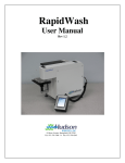
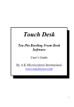
1
Phoenix LT4 Lane Machine Operation, Maintenance, and Parts Manual
6
7
8
9
Figure 3- 39
Table 3- 5
ID
6
Component
Vacuum Motor
Description
The combined motor and pump provide the suction
power for removing the cleaner and conditioner solution
from the lane. The unit contains a replaceable seal (P/N
A-8307) that provides an air tight connection between the
vacuum pump and waste tank.
7
Waste Tank
This tank is large enough to hold the cleaner, dirt, and oil
from the cleaning of approximately 16 lanes.
To keep cleaner suds from being sucked into the vacuum
pump, pour 1-2 ounces (30-60 ml) of defoamer into the
waste tank before use.
Empty the waste tank every time the cleaner tank is filled
during a lane cleaning session and before storing the
machine, though a full waste tank will not leak when the
machine is in the storage position.
The waste tank also has a line marked “MAX” and it
should be emptied once the level of the waste reaches
that line.
8
Vacuum Hose
This flexible tube is used to transport the oil/cleaner
solution from the vacuum head to the waste tank.
The hose slips onto the waste tank inlet tube. This slip
fitting makes it easy to take off the hose when removing
the waste tank.
9
Vacuum head
The agitator foam and squeegee are attached to the
body of the vacuum head. It is held up off the lane by a
solenoid except during a cleaning cycle or when power is
removed from the machine. The metal tube on the top
provides an attachment point for the vacuum hose.
3-20
Rev. Date: 12/12
61-900040-000