1
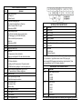
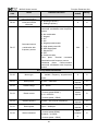
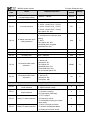
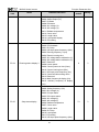
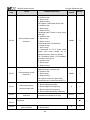
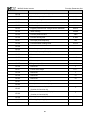
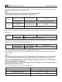
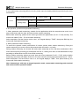
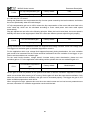
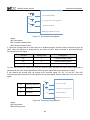
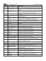
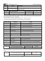
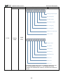
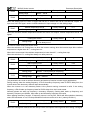
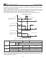
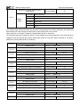
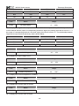
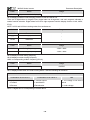
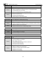
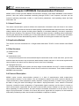
HATA PARAMETRELERİ
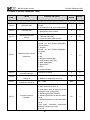
KOD
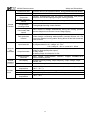
E01
E02
E03
E04
E05
E06
E07
E08
E09
E10
E11
E14
E16
E18
AÇIKLAMA
Motor Kısa devre
Aşırı Akım
Motor ve Kabloları Kontrol ediniz
Hızlanma ve Yavaşlama süresini artırınız
Motor ve Sürücüyü Büyütünüz
Aşırı Gerilim
Hızlanmada ve Yavaşlama sürelerini artırınız
Frenleme direnci ilave ediniz.
Besleme Hatası
Giriş gerilimi anormal kontrol ediniz.
Düşük Voltaj
Besleme Gerilimini kontrol ediniz
Cihazı bakıma gönderiniz
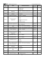
Inverter Aşırı yük.
Yük çok ağır veya motor mili kilitli
Motor Aşırı Yük
P9-01 uygun ayarlayın
Motor ve Sürücüyü Büyütünüz
IGBT Aşırı Isı
Ortam sıcaklığını düşürün
Sürücünün fanlarını kontrol ediniz
Sürücüyü bakıma gönderiniz
Haberleşme hatası
Akım Okuma Hatası
Sürücüyü bakıma Gönderiniz
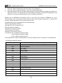
MICNO SERİSİ HIZ KONTROL CİHAZLARI
KOLAY KULLANIM KILAVUZU
Bu kılavuz kolay devreye almak için basitleştirilerek hazırlanmıştır. Tüm
detaylar için ana kullanma kılavuzunu okuyunuz!
v1.1
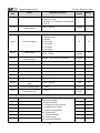
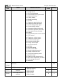
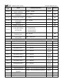
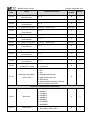
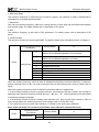
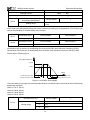
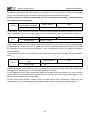
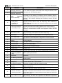
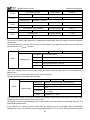
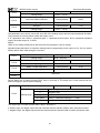
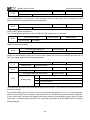
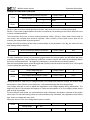
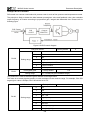
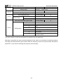
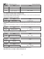
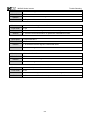
TEMEL PARAMETRE AYARLARI
KOD
AÇIKLAMA
P0-01 Kontrol Modu Seçimi
0: V/F Kontrol
1 Vektör Kontrol
P0-02 Run Komutu Kaynağı Seçimi
0: Tuş takımı üzerindeki Run ve Stop tuşu
1: Harici Terminal COM - D1 uçları
2: Haberleşme RS485
P0-03 Frekans Kaynağı Seçimi
1: Tuş Takımı üzerindeki yukarı ve aşağı tuşlar
2: AI1 Analog giriş 1. (AI1-GND-10V uçları)
4: Cihaz üzerindeki potansiyometre
6: Sabit Hız
9: Haberleşme RS485
P0-17 Hızlanma Zamanı (sn)
P0-18 Yavaşlama Zamanı (sn)
PC-00 0. Sabit Hız
P0-03 parametresi 6 set edilmelidir.
Cihaza start verildiğinde PC-00 daki hızda cihaz döner
PC-01 1.Sabit Hız
P0-03 6 set edilmelidir.
D2 dijital giriş P4-02 parametresi 12 ayarlanmalıdır.
D2-COM kısa devre yapıldığın 1. sabit hız seçilmiş olur
P0-10 Frekans üst değerini değiştirmek için P0-10 ve
P0-12 P0-12 parametrelerini beraber değiştiriniz.
P0-14 Frekans alt limit
PP-01 Fabrika ayarlarına geri dönme
1: Cihaz fabrika ayarlarına döner
P6-10 Stop Metodu Seçimi
0: Yavaşlamalı Stop
1: Serbest Stop
P6-11 DC Fren Başlama Frekansı
P6-13 DC Fren Akımı
P6-14 DC Fren Zamanı
P6-15 DC Fren uygulama oranı
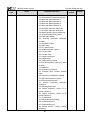
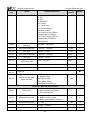
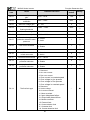
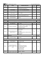
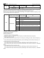
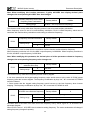
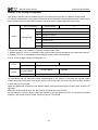
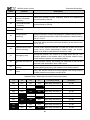
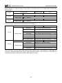
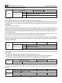
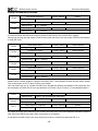
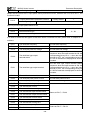
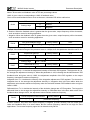
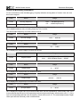
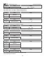
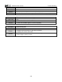
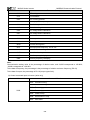
MOTOR İŞLETİM PARAMETRELERİ
KOD
AÇIKLAMA
P1-01
P1-02
P1-03
P1-04
P1-05
Motor Gücü
Motor Voltajı
Motor Akımı
Motor Frekansı
Motor devri
Motor Yüksüz Akımı, Motor nominal akımının yarısı
P1-10
girilmelidir.
P1-11
Autotune
1: Statik tune
2: Motor Dönerek
Autotune işlemine başlamadan önce, Motor plaka değerleri girilmelidir.
P1-11 parametresi 1 yapıldıktan sonra ekrana TUNE yazısı gelir.
Cihaz üzerindeki RUN komutuna basılarak tune işlemi başlatılır. (Tune
işlemi yapılabilmesi için P0-02=0 ayarlı olmalıdır.)
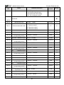
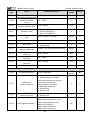
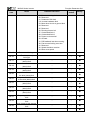
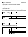
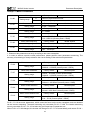
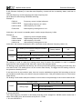
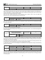
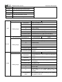
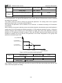
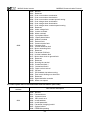
HABERLEŞME AYAR PARAMETRELERİ
KOD
AÇIKLAMA
Pd-00
RS485 Haberleşme Hızı
5 : 9600
6 : 19200
7 : 38400
Data Formatı
0 : 8-N-2
1 : 8-E-1
2 : 8-O-1
3 : 8-N-1
Cihaz adresi
Pd-01
Pd-02
Not: Sürücüyü devreye almadan önce motor plaka değerleri girilmelidir.
Preface
Thank you for purchasing MICNO series inverters.
This manual describes how to use MICNO series inverter properly. Please read it carefully before
installation, operation, maintenance and inspection. Besides, please use the product after understanding
the safety precautions.
Precautions
In order to describe the product’s details, the drawings presented in this instruction are
sometimes shown without covers or protective guards. When using the product, please make
sure to install the cover or protective guard as specified firstly, and operate the products in
accordance with the instructions.
Since the drawings in this manual are represented examples, some are subject to differ from
delivered products.
This manual may be modified when necessary because of improvement of the product,
modification or changes in specifications. Such modifications are denoted by a revised manual
No..
If you want to order the manual due to loss or damage, please contact our company agents in
each region or our company customer service center directly.
If there is still any problem during using the products, please contact our company customer
service center directly.
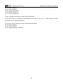
Contents
Chapter 1 Safety and Precautions ........................................................................................................ 1
1.1 Safety Precautions ................................................................................................................... 1
1.2 Precautions .............................................................................................................................. 3
Chapter 2 Product Information.............................................................................................................. 6
2.1 Product Inspection.................................................................................................................... 6
2.2 Model Description .................................................................................................................... 6
2.3 Description of Nameplate ......................................................................................................... 6
2.4 Selection Guide ........................................................................................................................ 7
2.5 Technical Specifications ............................................................................................................ 8
2.6 External & Installation Dimensions .......................................................................................... 10
2.7 Routine Maintenance of Inverter ............................................................................................. 19
2.8 Instructions on Warranty of Inverter ........................................................................................ 20
Chapter 3 Mechanical and Electric Installation .................................................................................. 21
3.1 Mechanical Installation ........................................................................................................... 21
3.2 Electrical Installation ............................................................................................................... 22
Chapter 4 Operation and Display ........................................................................................................ 34
4.1 Keypad Description ................................................................................................................ 34
4.2 Function Code Checking and Modification Methods Description ............................................. 36
4.3 Power-on Initialization ............................................................................................................ 36
4.4 Fault Protection ...................................................................................................................... 36
4.5 Stand By ................................................................................................................................ 37
4.6 Running ................................................................................................................................. 37
4.7 Password Setting ................................................................................................................... 37
4.8 Motor Parameters Autotuning ................................................................................................. 37
Chapter 5 Function Parameter List ..................................................................................................... 39
5.1 Basic Function Parameter Table ............................................................................................. 40
5.2 Monitoring Parameter Table ................................................................................................... 65
Chapter 6 Parameter Description ........................................................................................................ 67
Group P0 Basic Function ............................................................................................................. 67
Group P1 Motor Parameters ........................................................................................................ 76
Group P2 Vector Control Parameters ........................................................................................... 78
Group P3 V/F Control Parameters ................................................................................................ 81
Group P4 Input Terminal............................................................................................................... 84
Group P5 Output Terminal ............................................................................................................ 94
Group P6 Start and Stop Control .................................................................................................. 98
Group P7 Keypad and Display ................................................................................................... 103
Group P8 Enhanced Function .................................................................................................... 109
Group P9 Fault and Protection ................................................................................................... 118
Group PA PID Function .............................................................................................................. 124
Group PB Wobble Frequency, Fixed Length, Counting ............................................................... 130
Group PC Multi-step Command and Simple PLC Function ......................................................... 133
Group PD Communication Parameters ....................................................................................... 138
Group PP Function Code Management ...................................................................................... 138
Group A0 Torque Control Parameters ......................................................................................... 140
Group U0 Monitoring Parameters ............................................................................................... 142
Chapter 7 EMC (Electromagnetic Compatibility) .............................................................................. 149
7.1 Definition .............................................................................................................................. 149
7.2 EMC Standard Description ................................................................................................... 149
7.3 EMC Guide .......................................................................................................................... 149
Chapter 8 Trouble Shooting .............................................................................................................. 152
8.1 Fault and Trouble Shooting................................................................................................... 152
8.2 Common Faults and Solutions .............................................................................................. 159
Chapter 9 MODBUS Communication Protocol ................................................................................. 160
9.1 About Protocol ...................................................................................................................... 160
9.2 Application Method ............................................................................................................... 160
9.3 Bus Structure ....................................................................................................................... 160
9.4 Protocol Description ............................................................................................................. 160
9.5 Communication Data Structure ............................................................................................. 161
9.6 Command Code and Communication Data Description......................................................... 161
9.7 PD Group Communication Parameter Description ................................................................ 168
MICNO Series Inverter
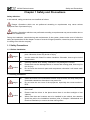
Safety and Precautions
Chapter 1 Safety and Precautions
Safety definition:
In this manual, safety precautions are classified as follows:
Danger: Operations which are not performed according to requirements may cause serious
equipment loss or personnel injury.
Caution: Operations which are not performed according to requirements may cause medium hurt or
light hurt or material loss.
During the installation, commissioning and maintenance of the system, please make sure to follow the
safety and precautions of this chapter. In case of a result of illegal operations, caused any harm and losses
is nothing to do with the company.
1.1 Safety Precautions
1.1.1 Before Installation:
Danger
Caution
Do not use the water-logged inverter, damaged inverter or inverter with missing
parts. Otherwise, there may be risk of injury.
Use the motor with Class B or above insulation. Otherwise, there may be risk of
electric shock.
Carefully handled when loading, otherwise it may damage the inverter.
Please don’t use the damaged driver or inverter with missing parts, there may be
risk of injury.
Do not touch the electronic parts and components; otherwise it will cause static
electricity.
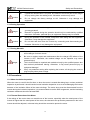
1.1.2 During Installation:
Danger
Caution
Install the inverter on incombustible surface such as metal, and keep away from
flammable substances. Otherwise it may cause fire.
Do not loose the set screw of the equipment, especially the screws marked in
RED.
Do not drop the cable residual or screw in the inverter. Otherwise it may damage
the inverter.
Please install the driver in the place where there is no direct sunlight or less
vibratory.
When more than two inverters are to be installed in one cabinet, due attention
should be paid to the installation locations (refer to Chapter 3 Mechanical and
Electrical Installation) to ensure the heat sinking effect.
1
MICNO Series Inverter
Safety and Precautions
1.1.3 During Wiring:
Danger
Caution
Operation should be performed by the professional engineering technician.
Otherwise there will be danger of electric shock!
There should be circuit breaker between the inverter and power supply.
Otherwise, there may be fire!
Make sure the power is disconnected prior to the connection. Otherwise there will
be danger of electric shock!
The ground terminal should be earthed reliably. Otherwise there may be danger of
electric shock.
Never connect AC power to output UVW terminals. Please note the remark of the
wiring terminals, connect them correctly. Otherwise may cause inverter damaged.
Ensure the wiring circuit can meet the requirement of EMC and the area safety
standard. Please follow the instructions in the manual before wiring. Otherwise
may cause injury or electric shock.
Never connect the braking resistor between DC bus (+), (-) terminals. Otherwise
may cause fire.
Encoder must be used together with shielded wire, and ensure the single terminal
of the shielded lay is connected with ground well.
1.1.4 Before Power-on:
Danger
Caution
Please confirm whether the power voltage class is consistent with the rated
voltage of the inverter and whether the I/O cable connecting positions are correct,
and check whether the external circuit is short circuited and whether the
connecting line is firm. Otherwise it may damage the inverter. The cover must be
well closed prior to the inverter power-on. Otherwise electric shock may be
caused.
The inverter is free from dielectric test because this test is performed prior to the
delivery. Otherwise accident may occur.
The cover must be well closed prior to the inverter power-on. Otherwise electric
shock may be caused!
Whether all the external fittings are connected correctly in accordance with the
circuit provided in this manual. Otherwise accident may occur!
1.1.5 After Power-on:
Danger
Do not open the cover of the inverter upon power-on. Otherwise there will be
danger of electric shock!
Do not touch the inverter and its surrounding circuit with wet hand. Otherwise
there will be danger of electric shock!
Do not touch the inverter terminals (including control terminal). Otherwise there
will be danger of electric shock!
At power-on, the inverter will perform the security check of the external
heavy-current circuit automatically. Thus, at the moment please do not touch the
terminals U, V and W, or the terminals of motor, otherwise there will be danger of
2
MICNO Series Inverter
Safety and Precautions
electric shock.
Caution
If parameter identification is required, due attention should be paid to the danger
of injury arising from the rotating motor. Otherwise accident may occur!
Do not change the factory settings at will. Otherwise it may damage the
equipment!
1.1.6 During Operation:
Danger
Caution
Do not touch the fan or discharge resistor to sense the temperature. Otherwise,
you may get burnt!
Detection of signals during the operation should only be conducted by qualified
technician. Otherwise, personal injury or equipment damage may be caused!
During the operation of the inverter, keep items from falling into the equipment.
Otherwise, it may damage the equipment!
Do not start and shut down the inverter by connecting and disconnecting the
contactor. Otherwise, it may damage the equipment!
1.1.7 During Maintain:
Danger
Do not repair and maintain the equipment with power connection. Otherwise there
will be danger of electric shock!
Be sure to conduct repair and maintenance after the charge LED indictor of the
inverter is OFF. Otherwise, the residual charge on the capacitor may cause
personal injury!
The inverter should be repaired and maintained only by the qualified person who
has received professional training. Otherwise, it may cause personal injury or
equipment damage!
Carry out parameter setting after replacing the inverter, all the plug-ins must be
plug and play when power outage.
1.2 Precautions
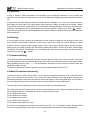
1.2.1 Motor Insulation Inspection
When the motor is used for the first time, or when the motor is reused after being kept, or when periodical
inspection is performed, it should conduct motor insulation inspection so as to avoid damaging the inverter
because of the insulation failure of the motor windings. The motor wires must be disconnected from the
inverter during the insulation inspection. It is recommended to use the 500V megameter, and the insulating
resistance measured should be at least 5MΩ.
1.2.2 Thermal Protection of the Motor
If the ratings of the motor does not match those of the inverter, especially when the rated power of the
inverter is higher than the rated power of the motor, the relevant motor protection parameters in the in the
inverter should be adjusted, or thermal relay should be mounted to protect the motor.
3
MICNO Series Inverter
Safety and Precautions
1.2.3 Running with Frequency higher than Standard Frequency
This inverter can provide output frequency of 0Hz to 3000Hz. If the user needs to run the inverter with
frequency of more than 50Hz, please take the resistant pressure of the mechanical devices into
consideration.
1.2.4 Vibration of Mechanical Device
The inverter may encounter the mechanical resonance point at certain output frequencies, which can be
avoided by setting the skip frequency parameters in the inverter.
1.2.5 Motor Heat and Noise
Since the output voltage of inverter is PWM wave and contains certain harmonics, the temperature rise,
noise and vibration of the motor will be higher than those at power frequency.
1.2.6 Voltage-sensitive Device or Capacitor Improving Power Factor at the Output Side
Since the inverter output is PWM wave, if the capacitor for improving the power factor or voltage-sensitive
resistor for lightning protection is mounted at the output side, it is easy to cause instantaneous over current
in the inverter, which may damage the inverter. It is recommended that such devices not be used.
1.2.7 Switching Devices like Contactors Used at the Input and Output terminal
If a contactor is installed between the power supply and the input terminal of the inverter, it is not allowed to
use the contactor to control the startup/stop of the inverter. If such contactor is unavoidable, it should be
used with interval of at least one hour. Frequent charge and discharge will reduce the service life of the
capacitor inside the inverter. If switching devices like contactor are installed between the output end of the
inverter and the motor, it should ensure that the on/off operation is conducted when the inverter has no
output. Otherwise the modules in the inverter may be damaged.
1.2.8 Use under voltage rather than rated voltage
If the KE series inverter is used outside the allowable working voltage range as specified in this manual, it
is easy to damage the devices in the inverter. When necessary, use the corresponding step-up or
step-down instruments to change the voltage.
1.2.9 Change Three-phase Input to Two-phase Input
It is not allowed to change the KE series three-phase inverter into two-phase one. Otherwise, it may cause
fault or damage to the inverter.
1.2.10 Lightning Impulse Protection
The series inverter has lightning over current protection device, and has certain self-protection capacity
against the lightning. In applications where lightning occurs frequently, the user should install additional
protection devices at the front-end of the inverter.
4
MICNO Series Inverter
Safety and Precautions
1.2.11 Altitude and Derating
In areas with altitude of more than 1,000 meters, the heat sinking effect of the inverter may turn poorer due
to rare air. Therefore, it needs to derate the inverter for use. Please contact our company for technical
consulting in case of such condition.
1.2.12 Certain Special Use
If the user needs to use the inverter with the methods other than the recommended wiring diagram in this
manual, such as shared DC bus, please consult our company.
1.2.13 Note of Inverter Disposal
The electrolytic capacitors on the main circuit and the PCB may explode when they are burnt. Emission of
toxic gas may be generated when the plastic parts are burnt. Please dispose the inverter as industrial
wastes.
1.2.14 Adaptable Motor
1) The standard adaptable motor is four-pole squirrel-cage asynchronous induction motor. If such motor is
not available, be sure to select adaptable motors in according to the rated current of the motor. In
applications where drive permanent magnetic synchronous motor is required, please consult our company;
2) The cooling fan and the rotor shaft of the non-variable-frequency motor adopt coaxial connection. When
the rotating speed is reduced, the cooling effect will be poorer. Therefore, a powerful exhaust fan should be
installed, or the motor should be replaced with variable frequency motor to avoid the over heat of the
motor.
3) Since the inverter has built-in standard parameters of the adaptable motors, it is necessary to perform
motor parameter identification or modify the default values so as to comply with the actual values as much
as possible, or it may affect the running effect and protection performance;
4) The short circuit of the cable or motor may cause alarm or explosion of the inverter. Therefore, please
conduct insulation and short circuit test on the newly installed motor and cable. Such test should also be
conducted during routine maintenance. Please note that the inverter and the test part should be completely
disconnected during the test.
5
MICNO Series Inverter
Product Information
Chapter 2 Product Information
2.1 Product Inspection
Checking the following items when receiving the inverter
Confirmation Items
Method
Confirm if the inverter is what you ordered
Check name plate
Damaged or not
Inspect the entire exterior of the inverter to see if
there are any scratches or other damage
resulting from shipping
Confirm if the fastening parts (screws, etc.)
are loose or not
Check with a screw driver if necessary
User’s manual, certification and other spares
User’s manual and the relative spares
Please contact the local agent or our company directly if there is any damage on the inverter.
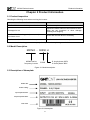
2.2 Model Description
MICNO – 00550 H
MICNO series
frequency inverter
5.5KW
S: single phase 220V
H: three phase 380V
Figure 2-1 Model description
2.3 Description of Nameplate
Model No.
Power rating
Input specification
Output specification
Bar code
Figure 2-2 Nameplate
6
MICNO Series Inverter
Safety and Precautions
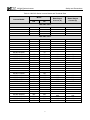
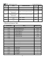
2.4 Selection Guide
Table 2-1 MICNO Series Inverter Model and Technical Data
Motor
Inverter Model
kW
HP
Rated Input
Current (A)
Rated Output
Current (A)
5.4
8.2
14
23
2.3
4
7
9.6
3.4
5.0
6.8
10
15
20
26
35
38
46
62
76
92
112
157
180
214
256
307
350
385
430
468
525
590
665
785
880
980
1130
2.1
3.8
6.0
9
13
17
25
32
37
45
60
75
90
110
150
176
210
253
304
340
377
423
465
520
585
650
725
860
950
1100
1AC 220V ±15%
MICNO-00040S
MICNO-00075S
MICNO-00150S
MICNO-00220S
0.4
0.75
1.5
2.2
0.5
1
2
3
3AC 380V ±15%
MICNO-00075H
MICNO-00150H
MICNO-00220H
MICNO-00370H
MICNO-00550H
MICNO-00750H
MICNO-01100H
MICNO-01500H
MICNO-01850H
MICNO-02200H
MICNO-03000H
MICNO-03700H
MICNO-04500H
MICNO-05500H
MICNO-07500H
MICNO-09000H
MICNO-11000H
MICNO-13200H
MICNO-16000H
MICNO-18500H
MICNO-20000H
MICNO-22000H
MICNO-25000H
MICNO-28000H
MICNO-31500H
MICNO-35000H
MICNO-40000H
MICNO-50000H
MICNO-56000H
MICNO-63000H
0.75
1.5
2.2
3.7
5.5
7.5
11
15
18.5
22
30
37
45
55
75
90
110
132
160
185
200
220
250
280
315
350
400
500
560
630
1
2
3
5
7.5
10
15
20
25
30
40
50
60
75
100
125
150
175
210
250
260
300
330
370
420
470
530
660
750
840
7
MICNO Series Inverter
Safety and Precautions
2.5 Technical Specifications
Table 2-2 MICNO Series Inverter Technical Specifications
Item
Technical Index
Input voltage
Specification
1AC 220V±15%, 3AC 380V±15%
Input
Input frequency
47~63Hz
Output voltage
0~rated input voltage
Output
Output frequency
Control mode
Operation command
mode
V/f control
Sensorless vector control
Torque control
Keypad control
Terminal control
Serial communication control
Frequency setting
mode
Digital setting, analog setting, pulse frequency setting, serial
communication setting, multi-step speed setting & simple PLC, PID
setting, etc. These frequency settings can be combinated & switched
in various modes.
Overload capacity
G model: 150% 60s, 180% 10s, 200% 3s.
P model: 120% 60s, 150% 10s, 180% 3s
Starting torque
Speed adjustment
range
Speed control
precision
Carrier frequency
Control
Features
V/f control: 0~3000Hz
Sensorless vector control: 0~300Hz
Frequency accuracy
Torque boost
0.5Hz/150% (SVC); 1Hz/150% (V/f)
1:100 (SVC), 1:50 (V/f)
±0.5% (SVC)
1.0--16.0kHz, automatically adjusted according to temperature and
load characteristics
Digital setting: 0.01Hz
Analog setting: maximum frequency ×0.05%
Automatically torque boost; manually torque boost: 0.1%~30.0%
V/f curve
Three types: linear, multiple point and square type (1.2 power, 1.4
power, 1.6 power, 1.8 power, square)
Acceleration/decele
ration mode
Straight line/S curve; four kinds of acceleration/deceleration time,
range: 0.1s~3600.0s
DC braking
DC braking when starting and stopping
DC braking frequency: 0.0Hz~maximum frequency, braking time:
0.0s~100.0s
Jog operation
Jog operation frequency: 0.0Hz~maximum frequency
Jog acceleration/deceleration time: 0.1s~3600.0s
Simple PLC &
multi-step speed
operation
It can realize a maximum of 16 segments speed running via the built-in
PLC or control terminal.
Built-in PID
Built-in PID control to easily realize the close loop control of the
process parameters (such as pressure, temperature, flow, etc.)
Automatic voltage
regulation
Keep output voltage constant automatically when input voltage
fluctuating
8
MICNO Series Inverter
Common DC bus
Torque control
Torque limit
Wobble frequency
control
Control
Function
Input/out
put
terminals
Environment
Torque control without PG
“Rooter” characteristics, limit the torque automatically and prevent
frequent over-current tripping during the running process
Multiple triangular-wave frequency control, special for textile
Timing/length/
counting control
Timing/length/counting control function
Over-voltage &
over-current stall
control
Limit current & voltage automatically during the running process,
prevent frequent over-current & over-voltage tripping
Fault protection
function
Up to 30 fault protections including over-current, over-voltage,
under-voltage, overheating, default phase, overload, shortcut, etc., can
record the detailed running status during failure & has fault automatic
reset function
Input terminals
Programmable DI: 7 on-off inputs, 1 high-speed pulse input
2 programmable AI: AI1: voltage -10~10V
A12: voltage 0~10V or current 0/4~20mA
Output terminals
Communication
terminals
Human
machine
interface
Safety and Precautions
Common DC bus for several inverters, energy balanced automatically
1 programmable open collector output: 1 analog output (open collector
output or high-speed pulse output)
2 relay output
2 analog output: 0/4~20mA or 0~10V
Multifunction key
Offer RS485 communication interface, support MODBUS-RTU
communication protocol
Display frequency setting, output frequency, output voltage, output
current, etc.
QUICK/JOG key, can be used as multifunction key
Ambient
temperature
-10℃~40℃, derated 4% when the temperature rise by every 1℃
(40℃~50 ℃).
Humidity
Altitude
Storage
temperature
90%RH or less (non-condensing)
≤1000M: output rated power, >1000M: output derated
LED display
-20℃~60℃
9
MICNO Series Inverter
Safety and Precautions
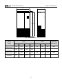
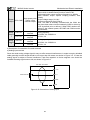
2.6 External & Installation Dimensions
2.6.1 Parts Description
Operation keypad
Cover installation hole
Cables crossing
Inverter mounting hole
10
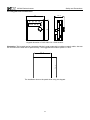
MICNO Series Inverter
Safety and Precautions
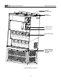
Inverter
mounting hole
Inverter
hoisting hole
Keypad bracket
Control board
Main circuit wiring
When installing a
cabinet, can outlet
front, back, left
and right
Figure 2-3 Parts of inverter
11
MICNO Series Inverter
Safety and Precautions
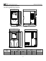
2.6.2 External & Installation Dimensions
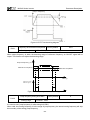
1AC 220V 0.4~2.2kW inverter dimension
78
124.8
73
128
73
M4
140
148.4
50.00
121.8
Grounding
1AC 220V 0.4~1.5kW
W
D
A
H
B
5 0 .0 0
1AC 220V 2.2kW
Power
Range
0.4~1.5kW
2.2kW
W
78
110
External Dimension
( mm )
H/H1
D/D1
140/148.4
185
124.8/121.8
153
12
Installation Dimension
( mm )
A
B
73
98
128
174
Mounting
Bolt Model
M4
M4
MICNO Series Inverter
Safety and Precautions
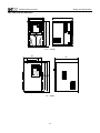
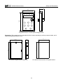
3AC 380V inverter dimension
W
D
A
B
H
5 0 .0 0
0.75~5.5kW
W
A
H2
B
H1
D
7.5~30kW
13
MICNO Series Inverter
Safety and Precautions
W
A
H2
B
H1
D
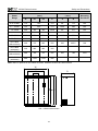
37~200kW
(including 90~200kW standard inverter)
W
D
H1
H2
5 0 .0 0
90~200kW nonstandard inverter (with base)
14
MICNO Series Inverter
Power
Range
Safety and Precautions
External Dimension
( mm )
W
H1
Installation Dimension
( mm )
H2
185
Mounting
Bolt Model
D
A
B
153
98
174
M4
0.75~2.2kW
110
3.7~5.5kW
135
173
122.6
229
M4
7.5~15kW
200
330
300
188.8
90
317
M4
18.5~30kW
255
440
403
229
140
423.6
M5
37~45kW
280
570
521
253
190
552
M6
55~75kW
320
600
552
330
230
582
M8
90~110kW
(without base)
320
715
662
356
230
695.5
M8
90~110kW
(with base)
320
992
962
356
132~200kW
(without base)
480
790
725
385
360
768
M10
132~200kW
(with base)
480
1165
1125
385
240
Note: Base is optional for 90~200kW inverters. Standard invertes are without base.
W
A2
A1
H2
B
H1
D
220~630kW without base
15
MICNO Series Inverter
Safety and Precautions
W
H2
H1
D
220~630kW with base
Power
Range
220~315kW
(without base)
220~315kW
(with base)
350~630kW
(without base)
350~630kW
(with base)
External Dimension
( mm )
Installation Dimension
( mm )
Mounting
Bolt Model
W
H1
H2
D
A1
A2
B
700
970
900
408
160
480
946
M10
700
1390
1350
408
940
1140
1100
458
240
660
1146
M10
940
1690
1650
458
16
MICNO Series Inverter
Safety and Precautions
2.6.3 Keypad External Dimension
58
30.2
76
5 0 .0 0
Keypad dimension of 1AC 220V 0.4~1.5kW inverter
Illustration: This keypad can be connected with the inverter externally by ordinary network cable, also can
be mounted on the front side of panel directly. The suggested thickness of panel is 1.2mm.
73.4
55.4
The installation size on the panel while using this keypad
17
MICNO Series Inverter
Safety and Precautions
27.4
65
100
15
Keypad dimension of other power rating inverters
Illustration: This keypad can be connected with the inverter externally by ordinary network cable, and it
needs an additional bracket to fix it.
69.5
16.6
108.3
1 0 4 . 5
73.3
65*100mm keypad bracket dimension
65*100mm hole dimension of keypad bracket
18
MICNO Series Inverter
Safety and Precautions
2.7 Routine Maintenance of Inverter
2.7.1 Routine Maintenance
The influence of the ambient temperature, humidity, dust and vibration will cause the aging of the devices
in the inverter, which may cause potential fault of the inverter or reduce the service life of the inverter.
Therefore, it is necessary to carry out routine and periodical maintenance on the inverter.
Routine inspection Items include:
1)
Whether there is any abnormal change in the running sound of the motor;
2)
Whether the motor has vibration during the running;
3)
Whether there is any change to the installation environment of the inverter;
4)
Whether the inverter cooling fan works normally;
5)
Whether the inverter has over temperature.
Routine cleaning:
1)
The inverter should be kept clean all the time.
2)
The dust on the surface of the inverter should be effectively removed, so as to prevent the dust
entering the inverter. Especially the metal dust is not allowed.
3)
The oil stain on the inverter cooling fan should be effectively removed.
2.7.2 Periodic Inspection
Please perform periodic inspection on the places where the inspection is a difficult thing.
Periodic inspection Items include:
1)
Check and clean the air duct periodically;
2)
Check if the screws are loose;
3)
Check if the inverter is corroded;
4)
Check if the wire connector has arc signs;
5)
Main circuit insulation test.
Remainder: When using the megameter (DC 500V megameter recommended) to measure the insulating
resistance, the main circuit should be disconnected with the inverter. Do not use the insulating resistance
meter to test the insulation of control circuit. It is not necessary to conduct the high voltage test (which has
been completed upon delivery).
2.7.3 Replacement of Vulnerable Parts for Inverter
The vulnerable parts of the inverter include cooling fan and filter electrolytic capacitor, whose service life
depends on the operating environment and maintenance status. General service life is shown as follows:
Part Name
Service Life
Fan
2~3 years
Electrolytic capacitor
4~5 years
The user can determine the year of replacement according to the operating time.
19
MICNO Series Inverter
1)
Safety and Precautions
Cooling fan
Possible reason for damage: Bearing is worn and blade is aging.
Judging criteria: Whether there is crack on the blade and whether there is abnormal vibration noise upon
startup.
2)
Filter electrolytic capacitor
Possible reason for damage: Input power supply in poor quality, high ambient temperature, frequent load
jumping, and electrolyte aging.
Judging criteria: Whether there is liquid leakage and whether the safe valve has projected, and measure
the static capacitance, and the insulating resistance.
2.7.4 Storage of Inverter
Upon acquiring the inverter, the user should pay attention to the following points regarding the temporary
and long-term storage of the inverter:
1)
Pack the inverter with original package and place back into the packing box of our company.
2)
Long-term storage will degrade the electrolytic capacitor. Thus, the product should be powered up
once every 2 years, each time lasting at least five hours. The input voltage should be increased slowly to
the rated value with the regulator.
2.8 Instructions on Warranty of Inverter
Free warranty only applies to the inverter itself.
1)
GMT provides 18 month warranty (starting from the date of original shipment as indicated on the
barcode) for the failure or damage under normal use conditions. If the equipment has been used for over
18 months, reasonable repair expenses will be charged.
2)
Reasonable repair expenses will be charged for the following situations within 18 months:
a)
The equipment is damaged because the user fails to comply with the requirements of the user’s
manual;
b)
Damage caused by fire, flood and abnormal voltage;
3)
Damage caused when the inverter is used for abnormal function.
The service expenses will be calculated according to the standard of the manufacturer. If there is any
agreement, the agreement should prevail.
20
MICNO Series Inverter
Mechanical and Electric Installation
Chapter 3 Mechanical and Electric Installation
3.1 Mechanical Installation
3.1.1 Installation environment
1) Ambient temperature: The ambient temperature exerts great influences on the service life of the inverter
and is not allowed to exceed the allowable temperature range (-10℃ to 50℃).
2) The inverter should be mounted on the surface of incombustible articles, with sufficient spaces nearby
for heat sinking. The inverter is easy to generate large amount of heat during the operation. The inverter
should be mounted vertically on the base with screws.
3) The inverter should be mounted in the place without vibration or with vibration of less than 0.6G, and
should be kept away from such equipment as punching machine.
4) The inverter should be mounted in locations free from direct sunlight, high humidity and condensate.
5) The inverter should be mounted in locations free from corrosive gas, explosive gas or combustible gas.
6) The inverter should be mounted in locations free from oil dirt, dust, and metal powder.
50.00
B
50.00
A
A
100 mm
50.00
B
Single Unit Installation Diagram
Installation Diagram of Upper and Down Parts
Figure 3-1 Installation Diagram
Single Unit Installation: When the inverter power is not higher than 22kW, the A size can be omitted. When
the inverter power is higher than 22kW, the A size should be higher than 50mm.
Installation of Upper and Lower Parts: When installing the upper and lower parts of the inverter, the
insulating splitter is required.
Power Rating
Mounting Dimension
B
A
≤15kW
≥100mm
≥50mm
18.5~30kW
≥200mm
≥50mm
≥37kW
≥300mm
≥50mm
21
MICNO Series Inverter
Mechanical and Electric Installation
3.1.2 Heat dissipation should be taken into account during the mechanical installation. Please pay
attention the following items:
1) Install the inverter vertically so that the heat may be expelled from the top. However, the equipment
cannot be installed upside down. If there are multiple inverters, parallel installation is a better choice. In
applications where the upper and lower inverters need to be installed, please refer to Figure 3-1 “MICNO
Series Inverter Installation Diagram” and install an insulating splitter.
2) The mounting space should be as indicated as Figure 3-1, so as to ensure the heat dissipation space of
the inverter. However, the heat dissipation of other devices in the cabinet should also be taken into
account.
3) The installation bracket must be flame retardant.
4) In the applications where there are metal dusts, it is recommended to mount the radiator outside the
cabinet. In this case, the space in the sealed cabinet should be large enough.
3.2 Electrical Installation
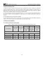
3.2.1 Guide to the external electrical parts
Table 3-1 Selection Guide of External Electrical Parts of MICNO Series Inverter
Inverter Model
Recommended Recommended
Recommended
Conducting
Circuit Breaker Recommended Conducting
Conducting
Wire
of
Main
Wire
of
Main
(MCCB)
Contactor
Wire of Control
Circuit at Input
Circuit at
Circuit
Side
Output Side
A
A
mm2
mm2
mm2
1AC 220V
MICNO-00040S
16
10
2.5
2.5
1.0
MICNO-00075S
16
10
2.5
2.5
1.0
MICNO-00150S
20
16
4.0
2.5
1.0
MICNO-00220S
32
20
6.0
4.0
1.0
22
MICNO Series Inverter
Inverter Model
Mechanical and Electric Installation
Recommended Recommended
Recommended
Conducting
Circuit Breaker Recommended Conducting
Conducting
Wire of Main Wire of Main
(MCCB)
Contactor
Wire of Control
Circuit at Input
Circuit at
Circuit
Side
Output Side
A
A
mm2
2
2
mm
mm
3AC 380V
MICNO-00075H
10
10
2.5
2.5
1.0
MICNO-00150H
16
10
2.5
2.5
1.0
MICNO-00220H
16
10
2.5
2.5
1.0
MICNO-00370H
25
16
4.0
4.0
1.0
MICNO-00550H
32
25
4.0
4.0
1.0
MICNO-00750H
40
32
4.0
4.0
1.0
MICNO-01100H
63
40
4.0
4.0
1.0
MICNO-01500H
63
40
6.0
6.0
1.0
MICNO-01850H
100
63
6.0
6.0
1.5
MICNO-02200H
100
63
10
10
1.5
MICNO-03000H
125
100
16
10
1.5
MICNO-03700H
160
100
16
16
1.5
MICNO-04500H
200
125
25
25
1.5
MICNO-05500H
200
125
35
25
1.5
MICNO-07500H
250
160
50
35
1.5
MICNO-09000H
250
160
70
35
1.5
MICNO-11000H
350
350
120
120
1.5
MICNO-13200H
400
400
150
150
1.5
MICNO-16000H
500
400
185
185
1.5
600
600
150*2
150*2
1.5
MICNO-22000H
600
600
150*2
150*2
1.5
MICNO-25000H
800
600
185*2
185*2
1.5
MICNO-28000H
800
800
185*2
185*2
1.5
MICNO-31500H
800
800
150*3
150*3
1.5
MICNO-20000H
MICNO-35000H
800
800
150*4
150*4
1.5
MICNO-40000H
1000
1000
150*4
150*4
1.5
MICNO-50000H
1200
1200
180*4
180*4
1.5
MICNO-56000H
1200
1200
180*4
180*4
1.5
MICNO-63000H
1500
1500
180*4
180*4
1.5
23
MICNO Series Inverter
Mechanical and Electric Installation
3.2.2 Connection to peripheral devices
Figure3-2 Diagram of the connection to peripheral devices
Do not install the capacitor or surge suppressor at the output side of the inverter, otherwise it may
cause inverter failure or capacitor and surge suppressor damaged.
The Inverter input / output (main circuit) contains harmonic components, it may interfere with inverter
24
MICNO Series Inverter
Mechanical and Electric Installation
accessories communications equipment. Therefore, please install anti-interference filter to minimize
interference.
The details of external devices and accessories selection refer to the manual of external devices.
3.2.3 Using instruction of the external electrical parts
Table 3-2 Using Instruction of the External Electrical Parts
Part Name
Installing Location
Function Description
Circuit breaker
Front end of input circuit
Disconnect the power supply when the equipment at the
lower part is over current.
Contactor
Between the circuit
breaker and the inverter
input side
Connection and disconnection of inverter. Frequent
power-on and power-off operations on the inverter should
be avoided.
AC input reactor Input side of the inverter
Improve the power factor of the input side;
Eliminate the higher harmonics of the input side effectively
and prevent other equipment from damaging due to
distortion of voltage wave.
Eliminate the input current unbalance due to unbalance
between the power phases.
EMC input filter
Reduce the external conduction and radiation interference
of the inverter.
Decrease the conduction interference flowing from the
power end to the inverter and improve the
anti-interference capacity of the inverter.
DC reactor
Input side of the inverter
Improve the power factor of the input side;
Improve the whole efficiency and thermal stability of the
DC reactor is optional for inverter.
inverters above 18.5kW Eliminate the impact of higher harmonics of the input side
on the inverter and reduce the external conduction and
radiation interference.
Between the inverter output side and the motor. close to
the inverter
The inverter output side generally has higher harmonics.
When the motor is far from the inverter, since there are
many distributed capacitors in the circuit, certain
Between the inverter harmonics may cause resonance in the circuit and bring
output side and the about the following two impacts:
AC output reactor
motor, close to the Degrade the motor insulation performance and damage
inverter
the motor for the long run.
Generate large leakage current and cause frequent
inverter protection.
In general, the distance between the inverter and the
motor exceeds 100 meters. Installation of output AC
reactor is recommended.
25
MICNO Series Inverter
Mechanical and Electric Installation
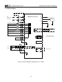
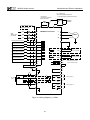
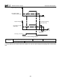
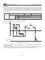
3.2.4 Wiring diagram
Instantaneous shortcut
protection circuit
1AC
220V±15%
50 / 60Hz
L
MICNO Series Inverter
U
Motor
V
N
W
Multi-functional On/off input 1
D1
Multi-functional On/off input 2
D2
Multi-functional On/off input 3
D3
Multi-functional On/off input 4
D4
Multi-functional On/off input 5
D5
J2
V
AO1
I
Analog Output
0~10V / 4~20mA
GND
HDI / D6
High-speed pulse input
or open collector input
COM
HDO
PLC
CME
High-speed pulse output
or open collector output
+24V
485+
PE
485-
+10V
Frequency setting
2k~10k
(ohm)
J1
AI1(0~10V / 4~20mA)
V
I
T1C
T1A
GND
T1B
PE
Figure 3-3 Wiring Diagram (single phase 0.4~1.5kW)
26
Relay Output 1
MICNO Series Inverter
Mechanical and Electric Installation
( 4≤15kW built-in
18.5~30kW optional for built-in
≥37kW optional for external connection )
DC Reactor
( optional for inverters
above 18.5kW )
P
P
Breaking
Resistor
Breaking
Unit
PB
N
Instantaneous shortcut
protection circuit
P1
R
3AC
380V±15%
50 / 60Hz
(+)
(-)
MICNO Series Inverter
S
V
T
W
Multi-functional On/off input 1
D1
Multi-functional On/off input 2
D2
Multi-functional On/off input 3
D3
Multi-functional On/off input 4
D4
J3
V
Multi-functional On/off input 5
D5
Multi-functional On/off input 6
D6
High-speed pulse input
U
AO1
I
GND
I
GND
J4
HDI / D7
V
Motor
Analog Output
0~10V / 4~20mA
AO2
Analog Output
0~10V / 4~20mA
or open collector input
HDO
CME
COM
High-speed pulse output
or open collector output
PLC
COM
+24V
485+
PE
485T1C
+10V
Frequency setting
2k~10k
(ohm)
J1
AI1(0~10V / 4~20mA)
T1A
I
V
Relay Output 1
T1B
J2
AI2(0~10V / 4~20mA)
V
I
T2C
GND
T2A
PE
T2B
Figure 3-4 Wiring Diagram (>1.5kW)
27
Relay Output 2
MICNO Series Inverter
Mechanical and Electric Installation
Note:
1. Terminal ◎ refers to the main circuit terminal, terminal ○ refers to the control circuit terminal.
2. Built-in braking unit is standard in the inverters below 18.5kW, and optional for 18.5 ~ 30kW
inverters.
3. Braking resistor is optional for user.
3.2.5 Main circuit terminals and connections
Danger
Make sure that the power switch is at OFF status prior to perform wiring
connection. Otherwise there may be danger of electric shock!
Only the qualified and trained personnel can perform wiring connection. Otherwise
it may cause equipment and human injuries!
It should be earthed reliably. Otherwise there may be danger of electric shock or
fire!
Caution
1)
Make sure that the rated value of the input power supply is consistent with that of
the inverter. Otherwise it may damage the inverter!
Make sure that the motor matches the inverter. Otherwise it may damage the motor
or generate inverter protection!
Do not connect the power supply to the terminals of U, V and W. Otherwise it may
damage the inverter!
Do not directly connect the brake resistor between the DC bus terminals (+) and (-).
Otherwise it may cause fire!
main circuit terminals diagram:
(+)
PB
Rb
L
N
U
V
W
Figure 3-5 Main circuit terminals diagram(Single phase 220V, 0.4~1.5kW)
(+)
PB
Rb
R
S
U
T
V
W
Figure 3-6 Main circuit terminals diagram(Three phase 220V, 0.4~1.5kW)
(+) (-) PB
Rb
L1
R
L2
T
S
U
V W
Figure 3-7 Main circuit terminals diagram(Three phase 380V, 1.5~5.5kW)
(+) (-) PB R
S
T
U
V
W
Figure 3-8 Main circuit terminals diagram(Three phase 380V, 7.5kW)
28
MICNO Series Inverter
Mechanical and Electric Installation
(+) (-) PB R
S
T
W
V
U
Figure 3-9 Main circuit terminals diagram(Three phase 380V, 11~15kW)
S
R
T (+) (-) PB U
V
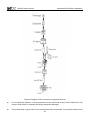
W
Figure 3-10 Main circuit terminals diagram(Three phase 380V, 18.5~30kW)
R S T P1 (+) (-) U V W
Figure 3-11 Main circuit terminals diagram(Three phase 380V, 37~75kW)
R
S
U
(-)
P1 (+)
T
V
W
Figure 3-12 Main circuit terminals diagram(Three phase 380V, 90~710kW)
2) Instructions of main circuit terminals
Terminal
Name
Description
R, S, T
Input terminal of three
Connect to three-phase AC power
phase power supply
(+) , (-)
Common DC bus input point (connection point of external
Negative and positive
brake unit of the inverter (220V and other voltages) above
terminals of DC bus
18.5kW)
(+) , PB
Connection terminal
of brake resistor
Connection point of brake resistor of the inverter below
15kW (220V) & the inverter below 18.5kW (other voltages)
P1, (+)
Connection terminal
of external DC reactor Connection point of external DC reactor
U, V, W
Output terminal of
inverter
Connect to the three phase motor
Earth terminal
Earth connection terminal
Precautions on Wiring:
a) Input power R, S and T:
There is no phase sequence requirement for the cable connection at the input side of the inverter,
b) DC bus (+) and (-) terminals:
Note that the (+) and (-) terminals of DC bus have residual voltage right after power-on. It needs to wait
until the CHARGE indictor is OFF and make sure that the voltage is less than 36V prior to wiring
connection. Otherwise there may be danger of electric shock.
29
MICNO Series Inverter
Mechanical and Electric Installation
When selecting external brake unit for the inverter above 18.5kW, the poles of (+) and (-) should not be
connected reversely, or it may damage the inverter and even cause fire.
The wiring length of the brake unit should not exceed 10 meters. Twisted wires or pair wires should be
used and connected in parallel.
Do not connect the brake resistor directly to the DC bus, or it may damage the inverter and even cause fire.
c) Connecting terminals (+) and PB of brake resistor:
The connecting terminals of the brake resistor are effective only for the inverter of less than 30kW with
built-in brake unit.
The prototype of brake resistor can refer to the recommended value and the wiring length should be less
than 5 meters. Otherwise it may damage the inverter.
d) Connecting terminals P1 and (+) of external DC reactor:
For the inverter above 18.5kW with external reactor, when assembling, remove the connector between
terminals P1 and (+), and connect a DC reactor instead.
e) Terminals U, V, W at the output side of the inverter:
The inverter output side cannot connect to the capacitor or surge absorber. Otherwise, it may cause
frequent inverter protection and even damage the inverter.
In case the motor cable is too long, it may generate electrical resonance easily due to the impact of
distributed capacitance, thus damaging the motor insulation or generating higher leakage current to invoke
over current protection of the inverter. When the length of motor cable is longer than 100 meters, it needs
to install a AC output reactor.
f) Earth terminal PE
:
This terminal should be earthed reliably, with resistance of earth cable of less than 0.1Ω. Otherwise, it may
cause fault or damage the inverter.
Do not share the earth terminal
and zero line of the power supply.
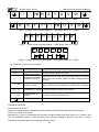
3.2.6 Control terminals and connections
1)
Control circuit terminals
AO1
RS485+ RS485-
COM
GND +10V
AI1
PLC
D1
+24V
D2
D4
D3
HDO
D5
T1A
T1B
T1C
HDI
Figure 3-13 Control Circuit Terminals(Singe phase 220V, 0.4~1.5kW)
AI1
AI2
AO1 AO2
RS485+ RS485-
GND
+10V GND
COM CME COM PLC +24V HDO
D1
D2
D3
D4
D5
D6
HDI
Figure 3-14 Control Circuit Terminals(2.2~710kW)
30
T1A
T1B T1C
T2A
T2B
T2C
MICNO Series Inverter
Mechanical and Electric Installation
2) Function description of control terminal
Table 3-3 Description of Control Terminal Function
Type
Power
Supply
Terminal
Symbol
Terminal Name
Function Description
+10V~
GND
External +10V
power
Provide +10V power supply for external units, and the
maximum output current is 10mA.
It is generally used as the operating power supply for the
external potentiometer. The potentiometer resistance range
is 1kΩ~5kΩ.
+24V~
COM
External +24V
power
Provide +24V power supply for external units. It is generally
used as the operating power supply for digital input/output
terminals and the external sensor.
The maximum output current is 200mA.
PLC
External power
input terminal
Connect to 24V by default upon delivery
When external signal is used to drive D1 ~ D6, and HDI,
PLC needs to connect to the external power supply and
disconnect from the +24V power terminal
AI1~GND
Analog input
terminal 1
1. Input range: DC 0V~10V/4mA~20mA, determined by J1
jumper on the control board.
2. Input impedance: 22kΩ (voltage); 500Ω(current)
AI2~GND
Analog input
terminal 2
1. Input range: DC 0V~10V/4mA~20mA, determined by J2
jumper on the control board.
2. Input impedance: 22kΩ (voltage); 500Ω(current)
D1
Digital input 1
D2
Digital input 2
D3
Digital input 3
D4
Digital input 4
D5
Digital input 5
D6
Digital input 6
Analog
Input
Digital
Input
Analog
Output
1. Optical coupling isolation, compatible with dual polarity
input
2. Input impedance: 4.7kΩ
3. Voltage range for level input: 9V ~ 30V
In addition to the characteristics of D1 to D6, it can also be
used as the high speed pulse input channel.
Maximum input frequency is 100kHz
HDI~CME/ High-speed pulse Caution: The CME is internally insulated with the COM, but
D7~COM
input terminal
they have been short circuited externally (HDI is driven by
+24V by default prior to delivery). When HDI needs to be
driven by the external power, the short circuited between
CME and COM must be disconnected.
The voltage or current output is determined by J3 jumper on
the control board.
AO1~GND Analog output 1
Output voltage range: 0V ~ 10V. Output current range: 0mA
~ 20mA.
AO2~GND
Analog output 2
The voltage or current output is determined by J4 jumper on
the control board.
Output voltage range: 0V ~ 10V. Output current range: 0mA
~ 20mA.
31
MICNO Series Inverter
Mechanical and Electric Installation
It can be used as high speed pulse output or open collector
output which is determined by function code P5-00.
High speed pulse output: maximum frequency is 100kHz
Open collector output :Optical coupling isolation, dual
polarity
High speed pulse
Digital
Output voltage range: 0V~24V
HDO~CME
output / open
Output
Output current range: 0mA~50mA
collector output
Note: The CME is internally insulated with the COM, but
they have been short circuited externally (HDO is driven by
+24V by default prior to delivery). When HDO needs to be
driven by the external power, the CME and COM must be
disconnected.
Normally closed Driving capacity:
Relay T1B-T1C
terminal
Output
AC 250V, 3A, COSø=0.4
Normally
open
1
T1A-T1C
DC 30V, 1A
terminal
Normally closed Driving capacity:
Relay T2B-T2C
terminal
Output
AC 250V, 3A, COSø=0.4
Normally open
2
T2A-T2C
DC 30V, 1A
terminal
3) Description of connection of control terminals
a) Analog input terminal
Since the weak analog voltage signal is easy to suffer external interferences, it needs to employ shielded
cable generally and the length should be no longer than 20 meters, as shown in Figure 3-5. In case the
analog signal is subject to severe interference, and filter capacitor or ferrite magnetic core should be
installed at analog signal source side, as shown in Figure 3-6.
less than 20 meters
+10V
Potentiometer
AI1
GND
PE
Figure 3-15 Connection of analog input
32
MICNO Series Inverter
Mechanical and Electric Installation
Cross in the same direction or wind 2
or 3 coils in the same direction
AI1
C
External analog source
0.022uF,50V
GND
Ferrite bead
Figure 3-16 Connection of analog Input
b) Digital input terminal
It needs to employ shielded cable generally, with cable length of no more than 20 meters. When active
driving is adopted, necessary filtering measures should be taken to prevent the interference to the power
supply.
It is recommended to use the contact control mode.
D1~D7 terminal connection: Drain wiring
+24V
+VCC
+24V
Signal
PLC
D1
3.3K
NPN
3.3Ω
D5
3.3K
0V
Inverter control board
COM
External controller
Figure 3-17 Drain wiring
33
MICNO Series Inverter
Operation and Display
Chapter 4 Operation and Display
4.1 Keypad Description
With the operation keypad, it can perform such operations on the inverter as function parameter
modification, working status monitor and running control (start and stop).
Figure4-1 Operation Keypad Diagram
1) Function key description
Function indicator
RUN
FWD/REV
LOCAL/REMOT
TUNE/TRIP
Description
Extinguished: stop status
Light on: operating status
Extinguished: forward operation
Light on: reverse operation
Extinguished: keypad control
Flickering: communication control
Light on: terminal control
Light on: torque control
Flickering slowly: parameter autotuning status
Flickering quickly: fault status
34
MICNO Series Inverter
Mechanical and Electric Installation
2) Unit indictor light description
Unit indictor
Description
Hz
Frequency unit
A
Current unit
V
Voltage unit
RPM
Rotation speed unit
%
Percentage
3) Digital display zone
Five-number digit LED display, can display setting frequency, output frequency, various monitoring data
and alarm code.
4) Keypad button description
Button
Name
PRG/ESC
Programming key
DATA/ENTER
Confirmation
key
Function
Entry and exit of primary menu
Progressively enter menu, and confirm parameters
Increment key
Progressively increase of data or function codes
Decrement key
Progressively decrease of data or function codes
Shift key
RUN
Running key
STOP/RST
Stop/reset
QUICK/JOG
Multi-function
selection key
Select the displayed parameters in turn on the stop display
interface and running display interface, and select the
modification bit of parameters when modifying parameters.
Start to run inverter under keyboard control mode
Stop inverter in running status and reset operation in fault alarm
status. The button’s characteristics are restricted by function
code P7-02.
According to P7-01, take function switching selection.
35
MICNO Series Inverter
Mechanical and Electric Installation
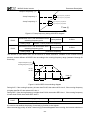
4.2 Function Code Checking and Modification Methods Description
The operation keypad of the MICNO Series Inverter adopts three-level menu structure to carry out
operations such as parameter setting.
The three-level menu includes function parameter group (level 1 menu) → Function code (level 2 menu) →
Function code setting value (level 3 menu). Refer to Figure 4-2 for the operation procedure.
Parameter code modification
PRG
Function code modification
ENTER
50.00
P0
Zero level menu
PRG
P0-08
First level menu
PRG
Setting value modification
ENTER
Second level menu
PRG
30.00
Third level menu
Figure 4-2 Operation Procedure of Three-level Menu
Description: When operating on level 3 menu, press PRG key or ENTER key to return to level 2 menu. The
difference between PRG key and ENTER key is described as follows: Pressing ENTER KEY will save the
setup parameter and return to the level 2 menu and then automatically shift to the next function code, while
pressing PRG key will directly return to level 2 menu without saving the parameter, and it will return to the
current function code.
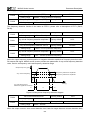
Example: Modify the function code P3-02 from 10.00Hz to 15.00Hz. (The bold-type word indicates the
flashing bit.)
50.00
PRG
P0
P3
ENTER
P3.00
P3-02
ENTER
PRG
P3
PRG
P3-03
PRG
015.00
010.00
010.00
In level 3 menu, if there is no flashing bit, it indicates that the function code cannot be modified. The
possible reasons include:
1) The function code is an unchangeable parameter, such as actual detection parameter, running record
parameter, etc.
2) The function code cannot be modified in running status. It can be modified only after the unit is stopped.
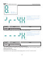
4.3 Power-on Initialization
Firstly the system initializes during the inverter power-on, and LED displays “8.8.8.8.8.8”. After initialization,
the inverter is in fault protection status if a fault happens, or the inverter is in stand-by status
4.4 Fault Protection
In fault status, inverter will display fault code & record output current, output voltage, etc. For details,
please refer to P9 (fault and protection) parameter group. Fault can be reset via STOP/RST key or external
terminals.
36
MICNO Series Inverter
Mechanical and Electric Installation
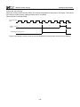
4.5 Stand By
In stop or stand by status, parameters of multi-status can be displayed. Whether or not to display this
parameter can be chosen through function code P7-05 (Stop status display parameter) according to binary
bits.
In stop status, there are thirteen parameters can be chosen to display or not. They are: setting frequency,
bus voltage, DI input status, DO output status, analog input AI1 voltage, analog input Al2 voltage, radiator
temperature, count value, actual length, PLC running step, load speed display, PID setting, HDI input pulse
frequency. The displaying of the chosen parameters can be switched in sequence by press “
” button.
Power on after power-off, the displayed parameters would be default considered as the chosen parameters
before power-off.
4.6 Running
In running status, there are thirty two parameters can be chosen to display or not through function code
P7-04 (running status display parameter 2) according to binary bits. They are: running frequency, setting
frequency, DC bus voltage, output voltage, output current, output torque, DI input status, DO output status,
analog input AI1 voltage, analog input AI2 voltage, radiator temperature, actual count value, actual length,
line speed, PID setting, PID feedback, etc. The displaying of the chosen parameters can be switched in
sequence by pressing “
” button.
4.7 Password Setting
The inverter provides user password protection function. When PP-00 is set to non-zero value, it indicates
the user password, and the password protection turns valid after exiting the function code editing status.
When pressing PRG key again, “------“ will be displayed, and common menu cannot be entered until user
password is input correctly.
To cancel the password protection function, enter with password and set PP-00 to “0”.
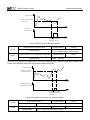
4.8 Motor Parameters Autotuning
To select the vector control running mode, it must input the nameplate parameter of the motor accurately
prior to the running of the inverter. The Inverter will select standard motor parameters matching the
nameplate parameter. Since the vector control mode relies highly on the motor parameters, it must acquire
the accurate parameters of the controlled motor to ensure the good control performance.
The procedures for the automatic tuning of motor parameters are described below:
First, select the command source (P0-02) as the command channel of the operation keypad. Second, input
the following parameters in accordance with the actual motor parameters:
P1-01: Rated motor power
P1-02: Rated motor voltage
P1-03: Rated motor current
P1-04: Rated motor frequency
P1-05: Rated rotation speed of motor
If the motor is completely disconnected from the load, set P1.11 to “2” (complete tuning), and press RUN
key on the keyboard keypad, then the inverter will automatically calculate the following parameters:
37
MICNO Series Inverter
Mechanical and Electric Installation
P1-06: Stator resistance
P1-07: Rotor resistance
P1-08: Leakage inductance
P1-09: Mutual inductance
P1-10: Current without load
Finally, complete the automatic tuning of motor parameters.
If the motor cannot be completely disconnected with the load, set P1-11 to “1” (static tuning), and then
press RUN key on the keyboard panel.
The following motor parameters can be calculated automatically:
P1-06: Stator resistance
P1-07: Rotor resistance
P1-08: Leakage inductive reactance
38
MICNO Series Inverter
Function Parameter List
Chapter 5 Function Parameter List
The function parameters of MICNO series inverter have been divided into 19 groups including P0~PP, A0,
U0 according to the function. Each function group contains certain function codes. For example, “P1-10”
means the tenth function code in the P1 function group. P0~PE are basic function parameter groups; PF is
factory parameter group (users are forbidden to access); A0 is torque control function parameter group; U0
is monitor function parameter group.
If PP-00 is set to non-zero value, it means parameter protection password is set, and the parameter menu
cannot be entered until correct password is input. To cancel the password, please set PP-00 to “0”.
A0 and U0 are default hidden parameter groups, which can be displayed by modifying PP-02.
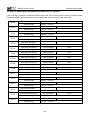
The instruction of the symbols in function parameter list is as following:
“○”:means that the parameter setting value can be modified on stop and running status.
“◎”:means that the parameter setting value cannot be modified on the running status.
“●”:means that the value of the parameter is the real detection value which cannot be modified.
39
MICNO Series Inverter
Function Parameter List
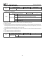
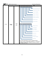
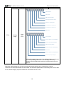
5.1 Basic Function Parameter Table
Function
code
Name
Factory
default
Modify
1
◎
0
◎
0
◎
1
◎
The same as P0-03
0
◎
0: Relative to maximum frequency
1: Relative to frequency source A
0
○
100%
○
00
○
Detailed instruction
P0 Group: Basic Function
P0-00
Inverter model
P0-01
Control mode
P0-02
Running command
source
P0-03
Main frequency source
A selection
P0-04
P0-05
P0-06
P0-07
Auxiliary frequency
source B selection
Reference of Frequency
source B
Range of Auxiliary
Frequency source B
Frequency source
selection
1: G model (constant torque load
model)
2: P model (fan and pump load model)
0: V/F control
1: Sensorless vector control
0: Keypad (LED OFF)
1: Terminal (LED ON)
2: Communication (LED flickers)
0: Keypad
(P0-08, UP and DOWN Adjustable,
non-recorded)
1: Keypad
(P0-08, UP and DOWN Adjustable,
recorded)
2: Al1
3: Al2
4: Keypad potentiometer
5: High speed pulse (HDI)
6: Multi-step speed
7: Simple PLC
8: PID
9: Communication
0%~150%
Units place: frequency source selection
0: Main frequency source A
1: Calculation result of frequency A and
B (determined by tens place)
2: Switching between A and B
3: Switching between A and calculation
result
4: Switching between B and calculation
result
Tens place: calculation relationship
between frequency A and B
0: A + B
40
MICNO Series Inverter
Function
code
Function Parameter List
Name
Detailed instruction
Factory
default
Modify
50.00Hz
○
0
○
50.00Hz
◎
0
◎
50.00Hz
○
1: A - B
2: Max (A, B)
3: Min (A, B)
P0-08
P0-09
P0-10
Keypad reference
frequency
Running direction
selection
Maximum frequency
0.00Hz ~ maximum frequency:P0-10
0: Forward
1: Reverse
50.00Hz ~ 300.00Hz
0: P0-12
1: AI1
2: AI2
3: Keypad potentiometer
4: HDI
5: Communication
P0-14 (frequency lower limit) ~ P0-10
(max. frequency)
P0-11
Frequency source
upper limit
P0-12
Frequency upper limit
P0-13
Frequency upper limit
offset
0.00Hz ~ P0-10 (max. frequency)
0.00Hz
○
P0-14
Frequency lower limit
0.00Hz ~ P0-12 (frequency upper limit)
0.00Hz
○
1.0kHz ~ 16.0kHz
Model
depend
○
1
○
P0-15
Carrier frequency
P0-16
Carrier frequency
adjusting according to
temperature
P0-17
Acceleration time 1
0.01s ~ 36000s
P0-18
Deceleration time 1
0.01s ~ 36000s
P0-19
ACC/DEC time unit
0: 1s
1: 0.1s
2: 0.01s
P0-21
Auxiliary frequency
source offset frequency
when combination
P0-22
Frequency command
resolution
P0-23
Digital setting frequency
storage selection when
stop
P0-24
P0-25
0: No
1: Yes
Model
depend
Model
depend
○
1
◎
0.00Hz
○
1: 0.1Hz
2: 0.01Hz
2
◎
0: Not store
1: store
1
○
0.00Hz ~ P0-10 (max. frequency)
●
Reserved
ACC/DEC time
reference frequency
○
0: P0-10 (max. frequency)
1: Setting frequency
41
0
◎
MICNO Series Inverter
Function
code
Name
Function Parameter List
Detailed instruction
Factory
default
Modify
0
◎
000
○
0
◎
2: 100Hz
P0-26
P0-27
Running frequency
command UP/DN
reference
0: Running frequency
1: Setting frequency
Command source
combination with
frequency source
Units
place:
Operation
keypad
command combination with frequency
source
0: No combination
1: Keypad
2: AI1
3: AI2
4: Keypad potentiometer
5: High speed pulse HDI
6: Multi-step speed
7: Simple PLC
8: PID
9: Communication
Tens place: Terminal command
combination with frequency source
Hundreds
place:
Communication
command combination with frequency
source
P1 Group: Motor Parameters
0: Common asynchronous motor
1: Variable frequency asynchronous
motor
P1-00
Motor type
P1-01
Rated power
0.1kW ~ 1000.0kW
P1-02
Rated voltage
1V ~ 2000V
P1-03
Rated current
0.01A ~ 655.35A
( Inverter power≤55kW )
0.1A ~ 6553.5A
Model
depend
Model
depend
Model
depend
◎
◎
◎
( Inverter power>55kW )
P1-04
Rated frequency
P1-05
Rated speed
P1-06
Stator resistance
0.00Hz ~ P0-10 (max. frequency)
1rpm ~ 36000rpm
0.001Ω ~ 65.535Ω
( Inverter power≤55kW)
0.0001Ω ~ 6.5535Ω
( Inverter power>55kW)
42
Model
depend
Model
depend
Motor
paramet
er
◎
◎
◎
MICNO Series Inverter
Function
code
P1-07
Function Parameter List
Name
Detailed instruction
Rotor resistance
0.001Ω ~ 65.535Ω
( Inverter power≤55kW)
0.0001Ω ~ 6.5535Ω
( Inverter power>55kW)
P1-08
Leakage inductance
0.01mH ~ 655.35mH
( Inverter power≤55kW)
0.001mH ~ 65.535mH
( Inverter power>55kW)
P1-09
Mutual inductance
0.01mH ~ 655.35mH
( Inverter power≤55kW)
0.001mH ~ 65.535mH
( Inverter power>55kW)
P1-10
No-load current
0.01A ~ P1-03 (rated current)
( Inverter power≤55kW)
0.1A ~ P1-03 (rated current)
( Inverter power>55kW)
P1-11
Parameters autotuning
0: No action
1: Static autotuning
2: Rotation autotuning
Factory
default
Modify
Motor
paramet
er
◎
Motor
paramet
er
◎
Motor
paramet
er
◎
Motor
paramet
er
◎
0
◎
30
○
0.50s
○
5.00Hz
○
20
○
1.00s
○
10.00Hz
○
P2 Group: Vector Control Parameters
P2-00
P2-01
P2-02
P2-03
P2-04
Speed loop proportional
gain 1
Speed loop integration
time 1
Low switching frequency
Speed loop proportional
gain 2
Speed loop integration
time 2
1 ~ 100
0.01s ~ 10.00s
0.00 ~ P2-05
1 ~ 100
0.01s ~ 10.00s
P2-05
High switching frequency
P2-02 ~ P0-10 (max. frequency)
P2-06
Vector control slip
compensation coefficient
50% ~ 200%
100%
○
P2-07
Speed loop filter time
0.000s ~ 0.100s
0.000s
○
P2-08
Vector control over
excitation gain
0 ~ 200
64
○
0: P2-10
1: AI1
2: AI2
3: Keypad potentiometer
4: High speed pulse HDI
5: Communication
0
○
P2-09
Torque upper limit source
selection in speed control
mode
43
MICNO Series Inverter
Function
code
Function Parameter List
Name
Detailed instruction
Factory
default
Modify
150.0%
○
6: Min (AI1, AI2)
7: Max (AI1, AI2)
Full scale of 1-7 selection corresponds
to P2-10
P2-10
Torque upper limit
digital setting
0.0% ~ 200.0%
P3 Group: V/F Control Parameters
0: Linear
1: Multiple-point
2: Square
3: 1.2 power
4: 1.4 power
6: 1.6 power
8: 1.8 power
0.0: auto
0.1% ~ 30.0%
0
◎
Model
depend
○
0.00Hz ~ P0-10 (max. frequency)
50.00Hz
◎
0.00Hz
◎
P3-00
V/F curve setting
P3-01
Torque boost
P3-02
Torque boost
cutoff frequency
P3-03
V/F frequency point 1
0.00Hz ~ P3-05
P3-04
V/F voltage point 1
0.0% ~ 100.0%
0.0%
◎
P3-05
V/F frequency point 2
P3-03 ~ P3-07
0.00Hz
◎
P3-06
V/F voltage point 2
0.0% ~ 100.0%
0.0%
◎
P3-07
V/F frequency point 3
0.00Hz
◎
P3-08
V/F voltage point 3
0.0% ~ 100.0%
0.0%
◎
P3-09
V/F slip compensation
gain
0.0% ~ 200.0%
0.0%
○
P3-10
V/F over excitation gain
0 ~ 200
64
○
P3-11
V/F oscillation
suppression gain
0 ~ 100
Model
depend
○
1
◎
2
◎
0
◎
0
◎
0
◎
0
◎
0
◎
P3-05 ~ P1-04 (motor rated power)
P4 Group: Input Terminal
P4-00
D1 terminal function
P4-01
D2 terminal function
P4-02
D3 terminal function
P4-03
D4 terminal function
P4-04
D5 terminal function
P4-05
D6 terminal function
P4-06
HDI terminal function
0: No function
1: Forward (FWD)
2: Reverse (REV)
3: Three-line running control
4: Forward Jog (FJOG)
5: Reverse Jog (RJOG)
6: Terminal UP
7: Terminal DOWN
8: Coast to stop
9: Fault reset (RESET)
44
MICNO Series Inverter
Function
code
Name
Function Parameter List
Detailed instruction
10: Pause running
11: External fault (normal open) input
12: Multi-step speed terminal 1
13: Multi-step speed terminal 2
14: Multi-step speed terminal 3
15: Multi-step speed terminal 4
16: ACC/DEC selection terminal 1
17: ACC/DEC selection terminal 2
18: Main frequency source switching
19: UP and DOWN setting clear
(terminal and keypad)
20: Running command switching
terminal
21: ACC/DEC invalid
22: PID Pause
23: PLC status reset
24: Wobble frequency pause
25: Counter input
26: Counter reset
27: Length count input
28: Length reset
29: Torque control invalid
30: PULSE frequency input (only valid
for HDI)
31: Reserved
32: DC braking command
33: External fault (normal closed)
input
34: Frequency modification enabled
35: PID action direction reverse
36: External stop terminal 1
37: Control command switching
terminal 2
38: PID integration stop
39: Switch frequency source A to
preset frequency
40: Switch frequency source B to
preset frequency
41, 42: Reserved
43: PID parameter switching
44: Customized fault 1
45: Customized fault 2
46: Speed control / torque control
switching
45
Factory
default
Modify
MICNO Series Inverter
Function
code
Name
Function Parameter List
Detailed instruction
Factory
default
Modify
47: Emergency stop
48: External stop terminal 2
49: Deceleration DC braking
50: The running time reset
P4-07
~
●
Reserved
P4-09
P4-10
Terminal filter time
0.000s ~ 1.000s
0: Two-line mode 1
1: Two-line mode 2
2: Three-line mode 1
3: Three-line mode 2
0.010s
○
0
◎
1.00Hz/s
○
P4-11
Terminal command mode
P4-12
UP/DN change rate
P4-13
AI curve 1 minimum input
0.00V ~ P4-15
0.00V
○
P4-14
AI curve 1 minimum input
corresponding setting
-100.0% ~ +100.0%
0.0%
○
P4-15
AI curve 1 maximum input
P4-13 ~ +10.00V
10.00V
○
P4-16
AI curve 1 maximum input
corresponding setting
-100.0% ~ +100.0%
100.0%
○
P4-17
AI1 filter time
0.00s ~ 10.00s
0.10s
○
P4-18
AI curve 2 minimum input
0.00V ~ P4-20
0.00V
○
P4-19
AI curve 2 minimum input
corresponding setting
-100.0% ~ +100.0%
0.0%
○
P4-20
AI curve 2 maximum input
P4-18 ~ +10.00V
10.00V
○
P4-21
AI curve 2 maximum input
corresponding setting
-100.0% ~ +100.0%
100.0%
○
P4-22
AI2 filter time
0.10s
○
P4-23
AI curve 3 minimum input
-10.00V ~ P4-25
-10.00V
○
P4-24
AI curve 3 minimum input
corresponding setting
-100.0% ~ +100.0%
0.0%
○
P4-25
AI curve 3 maximum input
P4-23 ~ +10.00V
10.00V
○
-100.0% ~ +100.0%
100.0%
○
0.10s
○
0.00kHz
○
P4-26
P4-27
AI curve 3 maximum input
corresponding setting
Keypad potentiometer
input filter time
0.001Hz/s ~ 50.000Hz/s
0.00s ~ 10.00s
0.00s ~ 10.00s
P4-28
HDI minimum input
P4-29
HDI minimum input
corresponding setting
0.00kHz ~ P4-30
-100.0% ~ 100.0%
0.0%
○
P4-30
HDI maximum input
P4-28 ~ 100.00kHz
50.00kHz
○
46
MICNO Series Inverter
Function
code
Name
P4-31
HDI maximum input
corresponding setting
P4-32
HDI filter time
Function Parameter List
Detailed instruction
-100.0% ~ 100.0%
0.00s ~ 10.00s
Units place: AI1
1: Curve 1 (see P4-13 ~ P4-16)
2: Curve 2 (see P4-18 ~ P4-21)
3: Curve 3 (see P4-23 ~ P4-26)
Tens place: AI2, ibid
Units place: AI1
0: Correspond to minimum input
setting
1: 0.0%
Tens place: AI2, ibid
Hundreds place: Keypad
potentiometer, ibid
Factory
default
Modify
100.0%
○
0.10s
○
321
○
000
○
P4-33
AI curve selection
P4-34
AI below minimum input
setting selection
P4-35
D1 delay time
0.0s ~ 3600.0s
0.0s
◎
P4-36
D2 delay time
0.0s ~ 3600.0s
0.0s
◎
P4-37
D3 delay time
0.0s ~ 3600.0s
0.0s
◎
00000
◎
00
◎
0
○
0
○
2
○
0
○
0: Active-high
1: Active-low
Units place: D1
Tens place: D2
Hundreds place: D3
Thousands place: D4
Ten thousands place: D5
0: Active-high
1: Active-low
Units place: D6
Tens place: HDI
P4-38
DI terminal valid mode
selection 1
P4-39
DI terminal valid mode
selection 2
P5-00
HDO terminal output
mode selection
P5-01
HDO open collector
output selection
P5-02
Relay T1 output selection
P5-03
Relay T2 output selection
P5 Group: Output Terminal
0: High speed pulse output
1: Open collector output
0: No output
1: Inverter is running
2: Fault output (fault stop)
3: FDT1 output
4: Frequency arrival
5: Zero-speed running (no output
when stop)
6: Motor overload pre-alarm
7: Inverter overload pre-alarm
8: Setting count value arrival
47
MICNO Series Inverter
Function
code
Name
Function Parameter List
Detailed instruction
Factory
default
Modify
9: Designated count value arrival
10: Length arrival
11: PLC loop completed
12: Accumulated running time arrival
13: Frequency limiting
14: Torque limiting
15: Ready for running
16: AI1>AI2
17: Frequency upper limit arrival
18: Frequency lower limit arrival
19: Under voltage status output
20: Communication setting
21: Orientation finished (reserved)
22: Orientation approach (reserved)
23: Zero-speed running 2 (output
when stop)
24: Accumulated power-on time arrival
25: FDT2 output
26: Frequency 1 arrival output
27: Frequency 2 arrival output
28: Current 1 arrival output
29: Current 2 arrival output
30: Timing arrival output
31: AI1 input over limit
32: Off load
33: Reverse running
34: Zero-current status
35: Module temperature arrival
36: Output current over limit
37: Lower limit frequency arrival
(output when stop)
38: Warning output (keep running)
39: Motor over temperature pre-alarm
40: This running time arrival
41: Reserved
P5-04
~
●
Reserved
P5-05
P5-06
P5-07
P5-08
HDO function selection
AO1 output function
selection
AO2 output function
selection
0: Running frequency
1: Setting frequency
2: Output current
3: Output torque
4: Output power
5: Output voltage
48
0
○
0
○
0
○
MICNO Series Inverter
Function
code
Function Parameter List
Name
Detailed instruction
Factory
default
Modify
50.00kH
z
○
6: Pulse input
7: AI1
8: AI2
9: Reserved
10: Length
11: Count value
12: Communication
13: Motor speed
14: Output current (100.0%
corresponds to 1000.0A)
15: Output voltage (100.0%
corresponds to 1000.0V)
16: Reserved
P5-09
HDO output maximum
frequency
0.01kHz ~ 100.00kHz
P5-10
AO1 offset coefficient
-100.0% ~ +100.0%
0.0%
○
P5-11
AO1 gain
-10.00 ~ +10.00
1.00
○
P5-12
AO2 offset coefficient
-100.0% ~ +100.0%
0.0%
○
P5-13
AO2 gain
-10.00 ~ +10.00
1.00
○
P5-17
HDO open collector
output delay time
0.0s ~ 3600.0s
0.0s
○
P5-18
Relay 1 output delay time
0.0s ~ 3600.0s
0.0s
○
P5-19
Relay 2 output delay time
0.0s ~ 3600.0s
0.0s
○
P5-20
P5-21
Reserved
P5-22
●
Output terminal valid
status selection
0: Positive logic
1: Negative logic
Units place: HDO
Tens place: Relay1
Hundreds place: Relay 2
000
○
0
○
0
◎
20
○
0.00Hz
○
0.0s
◎
P6 Group: Start and Stop Control
0: Direct start
1: Speed tracking and restart
2: Pre-excitation start
0: Begin from stop frequency
1: Begin from zero speed
2: Begin from maximum frequency
P6-00
Start mode
P6-01
Speed tracking mode
P6-02
Speed tracking speed
P6-03
Start frequency
0.00Hz ~ 10.00Hz
P6-04
Start frequency
0.0s ~ 100.0s
1 ~ 100
49
MICNO Series Inverter
Function
code
Name
Function Parameter List
Factory
default
Modify
0% ~ 100%
0%
◎
0.0s ~ 100.0s
0.0s
◎
0
◎
Detailed instruction
holding time
P6-05
P6-06
DC braking current before
start/pre-excitation
current
DC braking time before
start/pre-excitation time
0: Linear ACC/DEC
1: S-curve ACC/DEC A
2: S-curve ACC/DEC B
P6-07
ACC/DEC mode
P6-08
Time of S curve's start
part
0.0% ~ (100.0% ~ P6-09)
30.0%
◎
P6-09
Time of S curve's end part
0.0% ~ (100.0% ~ P6-08)
30.0%
◎
0
○
0.00Hz
○
0.0s ~ 100.0s
0.0s
○
0% ~ 100%
0%
○
0.0s ~ 100.0s
0.0s
○
100%
○
Model
depend
●
0
◎
1
○
81F
○
P6-10
P6-11
P6-12
P6-13
P6-14
P6-15
0: Deceleration to stop
1: Coast to stop
Stop mode
DC braking start
frequency after stop
DC braking delay time
after stop
DC braking current
after stop
DC braking time
after stop
Braking usage ratio
0.00Hz ~ P0-10 (maximum frequency)
0% ~ 100%
P7 Group: Keypad and Display
P7-00
Inverter rated power
P7-01
QUICK/JOG
function selection
P7-02
STOP/RST
function selection
P7-03
Running status display 1
0.1kW~1000.0kW
0: Invalid
1: Switching between keypad
command and remote command
(terminal command and
communication command)
2: FDW/REV Switching
3: Forward Jog
4: Reverse Jog
0: Valid when keypad control
1: Always valid
0000 ~ FFFF
Bit00: Running frequency 1 (Hz)
Bit01: Setting frequency (Hz)
Bit02: Bus voltage (V)
Bit03: Output voltage (V)
Bit04: Output current (A)
50
MICNO Series Inverter
Function
code
Function Parameter List
Factory
default
Modify
Running status display 2
0000 ~ FFFF
Bit00: PID feedback
Bit01: PLC step
Bit02: HDI input pulse frequency (kHz)
Bit03: Running frequency 2 (Hz)
Bit04: Remain running time
Bit05: AI1 voltage before calibration (V)
Bit06: AI2 voltage before calibration (V)
Bit07: Reserved
Bit08: Linear speed
Bit09: Current power-on time (Hour)
Bit10: Current running time (Min)
Bit11: HDI input pulse frequency (Hz)
Bit12: Communication setting value
Bit13: Reserved
Bit14: Main frequency A display (Hz)
Bit15: Auxiliary frequency B display
(Hz)
0
○
Stop status display
0000 ~ FFFF
Bit00: Setting frequency (Hz)
Bit01: Bus voltage (V)
Bit02: DI input status
Bit03: DO output status
Bit04: AI1 voltage(V)
Bit05: AI2 voltage(V)
Bit06: Radiator temperature
Bit07: Count value
Bit08: Length value
Bit09: PLC step
Bit10: Load speed
Bit11: PID setting
Bit12: HDI input pulse frequency (kHz)
73
○
Name
Detailed instruction
Bit05: Output power (kW)
Bit06: Output torque (%)
Bit07: DI status
Bit08: DO status
Bit09: AI1 voltage (V)
Bit10: AI2 voltage (V)
Bit11: Radiator temperature
Bit12: Count value
Bit13: Length value
Bit14: Load speed display
Bit15: PID setting
P7-04
P7-05
51
MICNO Series Inverter
Function
code
P7-06
P7-07
Function Parameter List
Factory
default
Modify
0.0001 ~ 6.5000
3.0000
○
0.0℃~ 100.0℃
-
●
Model
depend
●
0h ~ 65535h
-
●
Name
Detailed instruction
Load speed
display coefficient
IGBT module
temperature
P7-08
Inverter rated voltage
P7-09
Accumulated
running time
P7-10
Model No.
-
-
●
P7-11
Software version No.
-
-
●
0: 0 decimal place
1: 1 decimal place
2: 2 decimal places
3: 3 decimal places
1
○
0h ~ 65535h
-
●
0kW ~ 65535 kW
-
●
2.00Hz
○
P7-12
P7-13
P7-14
Load speed display
decimal place
Accumulated
Power-on time
Accumulated power
consumption
1V~2000V
P8 Group: Enhanced Function
P8-00
Jog running frequency
0.00Hz ~ P0-10 (max. frequency)
P8-01
Jog acceleration time
0.1s ~ 3600.0s
20.0s
○
P8-02
Jog deceleration time
0.1s ~ 3600.0s
20.0s
○
Model
depend
Model
depend
Model
depend
Model
depend
Model
depend
Model
depend
P8-03
Acceleration time 2
0.1s ~ 3600.0s
P8-04
Deceleration time 2
0.1s ~ 3600.0s
P8-05
Acceleration time 3
0.1s ~ 3600.0s
P8-06
Deceleration time 3
0.1s ~ 3600.0s
P8-07
Acceleration time 4
0.1s ~ 3600.0s
P8-08
Deceleration time 4
0.1s ~ 3600.0s
P8-09
Jump frequency 1
0.00Hz ~ P0-10 (maximum frequency)
0.00Hz
○
P8-10
Jump frequency 2
0.00Hz ~ P0-10 (maximum frequency)
0.00Hz
○
P8-11
Jump frequency
amplitude
0.00Hz ~ P0-10 (maximum frequency)
0.01Hz
○
P8-12
FWD/REV dead time
0.0s
○
P8-13
Reverse control
0
○
0.0s ~ 3600.0s
0: Enable
52
○
○
○
○
○
○
MICNO Series Inverter
Function
code
Name
Function Parameter List
Factory
default
Modify
0
○
0.00Hz
○
0h ~ 36000h
0h
○
0h ~ 36000h
0h
○
0: No protection
1: Protection
0
○
50.00Hz
○
0.0% ~ 100.0% (FDT1 level)
5.0%
○
0.0% ~ 100.0% (maximum frequency)
0.0%
○
0
○
0.00Hz ~ P0-10 (maximum frequency)
0.00Hz
○
0.00Hz ~ P0-10 (maximum frequency)
0.00Hz
○
0
○
50.00Hz
○
5.0%
○
0.00Hz ~ P0-10 (maximum frequency)
50.00Hz
○
0.0% ~ 100.0% (maximum frequency)
0.0%
○
0.00Hz ~ P0-10 (maximum frequency)
50.00Hz
○
0.0% ~ 100.0% (maximum frequency)
0.0%
○
0.0% ~ 300.0%
5.0%
○
Detailed instruction
1: Disable
P8-14
P8-15
P8-16
P8-17
P8-18
P8-19
P8-20
P8-21
P8-22
P8-25
P8-26
P8-27
P8-28
P8-29
P8-30
P8-31
P8-32
P8-33
P8-34
Action when setting
frequency lower than
frequency lower limit
Droop control
Accumulated power-on
arrival time
Accumulated running
arrival time
Power-on running
command valid protection
selection
Frequency detection
value (FDT1)
Frequency detection
lagging value
(FDT1)
Frequency arrival
detection amplitude
Jump frequency control
during ACC/DEC
Acceleration time 1 and
acceleration time 2
switching frequency point
Deceleration time 1 and
deceleration time 2
switching frequency point
Terminal jog priority
Frequency detection
value (FDT2)
Frequency detection
lagging value (FDT2)
Any arrival frequency
detection value 1
Any arrival frequency
detection amplitude 1
Any arrival frequency
detection value 2
Any arrival frequency
detection amplitude 2
Zero-current
0: Running at frequency lower limit
1: Stop
2: Zero-speed running
0.00Hz ~ 10.00Hz
0.00Hz ~ P0-10 (maximum frequency)
0: Invalid
1: Valid
0: Invalid
1: Valid
0.00Hz ~ P0-10 (maximum frequency)
0.0% ~ 100.0% (FDT2 level)
53
MICNO Series Inverter
Function
code
Function Parameter List
Name
Detailed instruction
detection level
100.0% corresponds to motor rated
current
Factory
default
Modify
0.10s
○
200.0%
○
0.00s
○
P8-35
Zero-current detection
delay time
P8-36
Output current over
limit value
P8-37
Output current over limit
detection delay time
P8-38
Any arrival current 1
0.0% ~ 300.0% (motor rated current)
100.0%
○
P8-39
Any arrival current 1
amplitude
0.0% ~ 300.0% (motor rated current)
0.0%
○
P8-40
Any arrival current 2
0.0% ~ 300.0% (motor rated current)
100.0%
○
P8-41
Any arrival current 2
amplitude
0.0% ~ 300.0% (motor rated current)
0.0%
○
P8-42
Timing function selection
0
○
0
○
0.0Min ~ 3600.0Min
0.0Min
○
0.00V ~ P8-46
3.10V
○
P8-45 ~ 10.00V
6.80V
○
0℃ ~ 100℃
75℃
○
0
○
0.01s ~ 360.00s
0.0% (No detection)
0.1% ~ 300.0% (motor rated current)
0.00s ~ 360.00s
0: Invalid 1: Valid
0:P8-44
1:AI1
P8-43
Timing running time
selection
2:AI2
3:Keypad potentiometer
Analog input scale corresponds to
F8-44
P8-44
P8-45
P8-46
P8-47
Timing running time
AI1 input voltage
protection lower limit
AI1 input voltage
protection upper limit
Module temperature
arrival
P8-48
Cooling fan control
0: Fan runs when inverter running
1: Fan always runs
P8-49
Wake up frequency
0.0 ~ PA-04 (PID given feedback
range)
3.0
○
P8-50
Wake up delay time
0.0s ~ 3600.0s
0.0s
○
P8-51
Dormancy frequency
0.00Hz ~ P0-10 (maximum frequency)
0.00Hz
○
P8-52
Dormancy delay time
0.0s ~ 3600.0s
0.0s
○
P8-53
Running arrival
time setting
0.0Min
○
P9-00
Motor overload protection
selection
1
○
0.0Min ~ 3600.0Min
P9 Group: Fault and Protection
0: Disable
1: Enable
54
MICNO Series Inverter
Function
code
P9-01
P9-02
Function Parameter List
Factory
default
Modify
0.20 ~ 10.00
1.00
○
50% ~ 100%
80%
○
0
○
130%
○
20
○
160%
○
0: Invalid
1: Valid
1
○
Name
Motor overload protection
gain
Motor overload pre-alarm
coefficient
Detailed instruction
P9-03
Stall over-voltage gain
P9-04
Stall over-voltage point /
Braking threshold
P9-05
Stall over current gain
1 ~ 100
P9-06
Stall over-current point
100% ~ 200%
P9-07
Short-circuit to ground
protection selection when
power-on
0 ~ 100
120% ~ 150%
P9-08
Fast current limitation
0: Not enabled
1: Enable
1
○
P9-09
Fault auto reset times
0~5
0
○
P9-10
Fault HDO acts selection
in fault auto reset
0: No action
1: Action
0
○
P9-11
Fault auto reset interval
0.1s ~ 100.0s
1.0s
○
0
○
1
○
-
●
P9-12
P9-13
Input phase failure
protection selection
Output phase failure
protection selection
0: Disable
1: Enable
0: Disable
1: Enable
0: No fault
1: Reserved
2: Acc over current
3: Dec over current
4: Over current in constant speed
5: Over voltage in Acc process
6: Over voltage in Dec process
P9-14
The first fault type
7: Over voltage in constant speed
8: Reserved
9: Under voltage
10: Inverter overload
11: Motor overload
12: Input side phase failure
13: Output side phase failure
14: Module overheat
1 5: External fault
16: Communication fault
17: Contactor fault
1 8: Current detection fault
55
MICNO Series Inverter
Function
code
Name
Function Parameter List
Factory
default
Modify
-
●
-
●
-
-
●
-
-
●
-
-
●
-
-
●
-
-
●
-
-
●
-
-
●
-
-
●
-
-
●
-
-
●
-
-
●
-
-
●
Detailed instruction
19: Motor autotuning fault
20: Reserved
21: Parameter R/W fault
2 2: Inverter hardware fault
23: Motor short circuit to ground fault
24: Reserved
25: Reserved
26: Running time arrival
27: Customized fault 1
28: Customized fault 2
29: Power-on time arrival
30: Off load
31: PID feedback lost when running
40: Fast current limiting over time
41: Reserved
42: Speed deviation oversize
43: Motor over speed
P9-15
P9-16
P9-17
P9-18
P9-19
P9-20
P9-21
P9-22
P9-23
P9-24
P9-27
P9-28
P9-29
P9-30
The second fault type
The third (latest)
fault type
Frequency at the third
(latest) fault
Current at the third
(latest) fault
Bus voltage at the third
(latest) fault
Input terminal’s status at
the third (latest) fault
Output terminal’s status
at the third (latest) fault
Inverter status at the third
(latest) fault
Power-on time at the third
(latest) fault
Running time at the third
(latest) fault
Frequency at the second
fault
Current at the second
fault
Bus voltage at the second
fault
Input terminal’s status at
56
MICNO Series Inverter
Function
code
Name
Function Parameter List
Detailed instruction
Factory
default
Modify
-
-
●
-
-
●
-
-
●
-
-
●
the second fault
P9-31
P9-32
P9-33
P9-34
Output terminal’s status
at the second fault
Inverter status at the
second fault
Power-on time at the
second fault
Running time at the
second fault
P9-37
Frequency at the first fault
-
-
●
P9-38
Current at the first fault
-
-
●
-
-
●
-
-
●
-
-
●
-
-
●
-
-
●
-
-
●
00000
○
00000
○
P9-39
P9-40
P9-41
P9-42
P9-43
P9-44
Bus voltage at the first
fault
Input terminal’s status at
the first fault
Output terminal’s status
at the first fault
Inverter status at the first
fault
Power-on time at the first
fault
Running time at the first
fault
P9-47
Action selection 1 for fault
protection
P9-48
Fault protection action
selection 2
Units place: Motor overload (11)
0: Coast to stop
1: Dec-to-stop
2: Keep running
Tens place: Input phase failure (12)
Hundreds place: Output phase failure
(13)
Thousands place: External fault (15)
Ten thousands place: communication
fault (16)
Units place: Encoder/PG card fault
0: Coast to stop
Tens place: Function code R/W fault
0: Coast to stop
1: Dec-to-stop
Hundreds place: Reserved
Thousands place: Motor over heat (25)
Ten thousands: Running time arrival
(26)
57
MICNO Series Inverter
Function
code
Name
P9-49
Fault protection action
selection 3
P9-50
Fault protection action
selection 4
P9-54
Running frequency
selection when fault
P9-55
Abnormal backup
frequency
Function Parameter List
Detailed instruction
Units place: Customized fault 1 (27)
0: Coast to stop
1: Dec-to-stop
2: Keep running
Tens place: Customized fault 2 (28)
0: Coast to stop
1: Dec-to-stop
2: Keep running
Hundreds place: Power-on time arrival
time (29)
0: Coast to stop
1: Dec-to-stop
2: Keep running
Thousands place: Off load (30)
0: Coast to stop
1: Dec-to-stop
2: Decelerate to 7% of motor rated
power, then keep running; run at
setting frequency when no off-load
Ten thousands place: PID feedback
lost when running (31)
0: Coast to stop
1: Dec-to-stop
2: Keep running
Units place:
Speed deviation oversize (42)
0: Coast to stop
1: Dec-to-stop
2: Keep running
Tens place: motor over speed (43)
Hundreds place: Initial place fault (51)
0: Run at current running frequency
1: Run at setting frequency
2: Run at upper limit frequency
3: Run at lower limit frequency
4: Run at abnormal backup frequency
60.0% ~ 100.0% (100.0% corresponds
to maximum frequency( P0-10))
Factory
default
Modify
00000
○
00000
○
0
○
100.0%
○
P9-56
~
●
Reserved
P9-58
P9-59
Instantaneous power-off
action selection
0: Invalid
1: Deceleration
58
0
○
MICNO Series Inverter
Function
code
Name
Function Parameter List
Factory
default
Modify
80 ~ 100.0%
90.0%
○
0.00s ~ 100.00s
0.50s
○
80.0%
○
0
○
10.0%
○
1.0s
○
0
○
0.0
○
0
○
0
○
100.0
○
20.0
○
Detailed instruction
2: Dec-to-stop
P9-60
P9-61
P9-62
P9-63
Recover judgment
voltage when
Instantaneous power-off
Recover judgment time
when Instantaneous
power-off
Action judgment voltage
when instantaneous
power-off
Off-load protection
selection
60.0% ~
voltage)
100.0%
(standard
bus
0: Disable
1: Enable
P9-64
Off-load detection level
0.0 ~ 100.0%
P9-65
Off-load detection time
0.0 ~ 60.0s
PA Group: PID Function
PA-00
PID given source
PID given through
PA-01
keypad
PA-02
PID feedback source
PA-03
PID action direction
PA-04
PID given feedback range
PA-05
Proportional gain Kp1
0: PA-01
1: AI1
2: AI2
3: Keypad potentiometer
4: High speed pulse HDI
5: Communication
6: Multi-step command
0.0 ~ PA-04 (PID given feedback
range)
0: AI1
1: AI2
2: Keypad potentiometer
3: AI1-AI2
4: High speed pulse HDI
5: Communication
6: AI1+AI2
7: MAX (|AI1|, |AI2|)
8: MIN (|AI1|, |AI2|)
0: Positive
1: Negative
PA-01(PID given through keypad)~
1000.0
0.0 ~ 100.0
PA-06
Integration time Ti1
0.01s ~ 10.00s
2.00s
○
PA-07
Differential time Td1
0.000s ~ 10.000s
0.000s
○
59
MICNO Series Inverter
Function
code
Name
PA-08
Cutoff frequency
of PID reverse
PA-09
PID deviation limit
PA-10
PID differential amplitude
Function Parameter List
Factory
default
Modify
0.00Hz
○
0.0% ~ 100.0%
0.0%
○
0.00% ~ 100.00%
0.10%
○
Detailed instruction
0.00 ~ P0-10 (maximum frequency)
PA-11
PID given filter time
0.00 ~ 650.00s
0.00s
○
PA-12
PID feedback filter time
0.00 ~ 60.00s
0.00s
○
PA-13
PID output filter time
0.00 ~ 60.00s
0.00s
○
0.0 ~ 100.0
20.0
○
PA-14
○
Reserved
PA-15
Proportional gain Kp2
PA-16
Integration time Ti2
0.01s ~ 10.00s
2.00s
○
PA-17
Differential time Td2
0.000s ~ 10.000s
0.000s
○
PID parameter
switching condition
0: No switching
1: Switching via terminals
2: Automatic switching according to the
deviation
0
○
0.0% ~ PA-20
20.0%
○
PA-19 ~ 100.0%
80.0%
○
0.0% ~ 00.0%
0.0%
○
0.00 ~ 360.00s
0.00s
○
0.00% ~ 100.00%
1.00%
○
0.00% ~ 100.00%
1.00%
○
00
○
0.0%
○
0.0s
○
PA-18
PA-19
PA-20
PA-21
PA-22
PA-23
PA-24
PID parameter switching
deviation 1
PID parameter switching
deviation 2
PID initial value
PID initial value holding
time
Forward maximum value
between two output
deviation
Reverse maximum value
between two output
deviation
PA-25
PID integration attribute
PA-26
PID feedback lost
detection value
PA-27
PID feedback lost
detection time
Units place: Integration separate
0: Invalid
1: Valid
Tens place: Stop integrating or not after
output reach limit
0: Keep integrating
1: Stop integrating
0.0%: No judgment for feedback lost
0.1% ~ 100.0%
0.0s ~ 20.0s
60
MICNO Series Inverter
Function
code
Name
PA-28
PID stop calculation
Function Parameter List
Factory
default
Modify
1
○
0
○
0.0% ~ 100.0%
0.0%
○
0.0% ~ 50.0%
0.0%
○
Detailed instruction
0: No calculation when stop
1: Calculation when stop
Pb Group: Wobble Frequency, Fixed Length, Counting
Pb-00
Pb-01
Pb-02
Wobble frequency setting
mode
Wobble frequency
amplitude
Sudden Jump
frequency amplitude
0: Relative to center frequency
1: Relative to maximum frequency
Pb-03
Wobble frequency cycle
0.1s ~ 3000.0s
10.0s
○
Pb-04
Triangular wave rise time
of wobble frequency
0.1% ~ 100.0%
50.0%
○
Pb-05
Setting length
0m ~ 65535m
1000m
○
Pb-06
Actual length
0m ~ 65535m
0m
○
Pb-07
Number of pulses
per meter
0.1 ~ 6553.5
100.0
○
Pb-08
Setting count value
1 ~ 65535
1000
○
Pb-09
Designated count value
1 ~ 65535
1000
○
PC Group: Multi-step Command and Simple PLC
PC-00
Multi-step command 0
-100.0% ~ 100.0%
0.0%
○
PC-01
Multi-step command 1
-100.0% ~ 100.0%
0.0%
○
PC-02
Multi-step command 2
-100.0% ~ 100.0%
0.0%
○
PC-03
Multi-step command 3
-100.0% ~ 100.0%
0.0%
○
PC-04
Multi-step command 4
-100.0% ~ 100.0%
0.0%
○
PC-05
Multi-step command 5
-100.0% ~ 100.0%
0.0%
○
PC-06
Multi-step command 6
-100.0% ~ 100.0%
0.0%
○
PC-07
Multi-step command 7
-100.0% ~ 100.0%
0.0%
○
PC-08
Multi-step command 8
-100.0% ~ 100.0%
0.0%
○
PC-09
Multi-step command 9
-100.0% ~ 100.0%
0.0%
○
PC-10
Multi-step command 10
-100.0% ~ 100.0%
0.0%
○
PC-11
Multi-step command 11
-100.0% ~ 100.0%
0.0%
○
PC-12
Multi-step command 12
-100.0% ~ 100.0%
0.0%
○
PC-13
Multi-step command 13
-100.0% ~ 100.0%
0.0%
○
PC-14
Multi-step command 14
-100.0% ~ 100.0%
0.0%
○
PC-15
Multi-step command 15
-100.0% ~ 100.0%
0.0%
○
61
MICNO Series Inverter
Function
code
Name
PC-16
Simple PLC running
mode
PC-17
Simple PLC storage
selection when
power-down
PC-18
0th phase running time
PC-19
0th phase ACC/DCC
time selection
st
PC-20
1 phase running time
PC-21
1st phase ACC/DCC
time selection
PC-22
PC-23
PC-24
nd
2
phase running time
2nd phase ACC/DCC
time selection
rd
3 phase running time
Function Parameter List
Detailed instruction
0: Stop after one cycle
1: Keep last frequency after one cycle
2: Circular running
Units place: Storage selection when
power-off
0: Not store
1: Store
Tens place: Storage selection when
stop
0: Not store
1: Store
0.0s (m) ~ 6500.0s (m)
0~3
0.0s (m) ~ 6500.0s (m)
0~3
0.0s (m) ~ 6500.0s (m)
0~3
0.0s (m) ~ 6500.0s (m)
Factory
default
Modify
0
○
00
○
0.0s (m)
○
0
○
0.0s (m)
○
0
○
0.0s (m)
○
0
○
0.0s (m)
○
0
○
0.0s (m)
○
0
○
0.0s (m)
○
0
○
0.0s (m)
○
0
○
0.0s (m)
○
0
○
0.0s (m)
○
0
○
0.0s (m)
○
rd
PC-25
3 phase ACC/DCC
time selection
PC-26
4th phase running time
0~3
0.0s (m) ~ 6500.0s (m)
th
PC-27
4 phase ACC/DCC
time selection
PC-28
5th phase running time
PC-29
5th phase ACC/DCC
time selection
th
PC-30
6 phase running time
PC-31
6th phase ACC/DCC
time selection
th
PC-32
7 phase running time
PC-33
7th phase ACC/DCC
time selection
PC-34
th
8 phase running time
0~3
0.0s (m) ~ 6500.0s (m)
0~3
0.0s (m) ~ 6500.0s (m)
0~3
0.0s (m) ~ 6500.0s (m)
0~3
0.0s (m) ~ 6500.0s (m)
th
PC-35
8 phase ACC/DCC
time selection
PC-36
9th phase running time
0~3
0.0s (m) ~ 6500.0s (m)
62
MICNO Series Inverter
Function
code
Name
PC-37
9th phase ACC/DCC
time selection
PC-38
Function Parameter List
Factory
default
Modify
0
○
0.0s (m)
○
0
○
0.0s (m)
○
0
○
0.0s (m)
○
0
○
0.0s (m)
○
0
○
0.0s (m)
○
0
○
0.0s (m)
○
0
○
0
○
0
○
0: 300BPS
1: 600BPS
2: 1200BPS
3: 2400BPS
4: 4800BPS
5: 9600BPS
6: 19200BPS
7: 38400BPS
5
○
0: No parity check (8-N-2)
1: Even parity check (8-E-1)
0
○
Detailed instruction
th
10 phase running time
0~3
0.0s (m) ~ 6500.0s (m)
th
PC-39
10 phase ACC/DCC
time selection
PC-40
11th phase running time
PC-41
11th phase ACC/DCC
time selection
PC-42
12th phase running time
PC-43
12th phase ACC/DCC
time selection
th
PC-44
13 phase running time
PC-45
13th phase ACC/DCC
time selection
th
PC-46
14 phase running time
PC-47
14th phase ACC/DCC
time selection
PC-48
th
15 phase running time
0~3
0.0s (m) ~ 6500.0s (m)
0~3
0.0s (m) ~ 6500.0s (m)
0~3
0.0s (m) ~ 6500.0s (m)
0~3
0.0s (m) ~ 6500.0s (m)
0~3
0.0s (m) ~ 6500.0s (m)
th
PC-49
PC-50
PC-51
15 phase ACC/DCC
time selection
Timing unit
(Simple PLC mode)
Multi-step command 0
given mode
0~3
0: s (second)
1: m (minute)
0: PC-00
1: AI1
2: AI2
3: Keypad potentiometer
4: High speed pulse HDI
5: PID control
6: Keypad setting frequency (P0-08),
can be modified via UP/DN
Pd Group: Communication Parameters
Pd-00
Baud rate
Pd-01
Data format
63
MICNO Series Inverter
Function
code
Function Parameter List
Factory
default
Modify
1 ~ 247, 0 is broadcast address
1
○
0ms ~ 20ms
2
○
0.0
○
1
○
0
○
Name
Detailed instruction
2: Odd parity check (8-O-1)
3: No parity check (8-N-1)
Pd-02
Local address
Pd-03
Response delay
Pd-04
Pd-05
Pd-06
Communication
timeout time
Communication
protocol selection
0.0 (invalid)
0.1s ~ 60.0s
0: Non-standard MODBUS protocol
1: Standard MODBUS protocol
Communication read
current resolution
0: 0.01A
1: 0.1A
PE Group: Reserved Function
FE-00
○
Reserved
PP Group: Function Code Management
PP-00
User password
PP-01
Parameter initialization
PP-02
Function parameter group
display selection
PP-03
Reserved
0 ~ 65535
0: No action
1: Restore factory default, but not
including motor parameters
2: Clear the record
Units place: U0 group display selection
0: No display
1: Display
Tens place: A0 group display selection
0: No display
1: Display
0
○
0
◎
00
◎
●
PP-04
Function code
modification attribute
A0-00
Speed/torque control
mode selection
A0-01
Torque setting source
selection in torque control
mode
A0-03
Torque setting throught
keypad in torque control
0: Disable
1: Enable
0
○
0
◎
0
◎
150.0%
○
A0 Group: Torque Control Parameters
0: Speed control
1: Torque control
0: Keypad (A0-03)
1: AI1
2: AI2
3: Keypad potentiometer
4: High speed pulse HDI
5: Communication
6: Min (AI1,AI2)
7: Max (AI1,AI2)
-200.0% ~ 200.0%
64
MICNO Series Inverter
Function
code
Function Parameter List
Factory
default
Modify
0.00s
○
0.00Hz ~ P0-10 (maximum frequency)
50.00Hz
○
0.00Hz ~ P0-10 (maximum frequency)
50.00Hz
○
0.00s ~ 36000s
0.00s
○
0.00s ~ 36000s
0.00s
○
Name
Detailed instruction
mode
A0-04
A0-05
A0-06
A0-07
A0-08
Torque filter time
Forward maximum
frequency in torque
control mode
Reverse maximum
frequency in torque
control mode
Acc time in torque control
mode
Dec time in torque control
mode
0.00s ~ 10.00s
5.2 Monitoring Parameter Table
Function code
Name
Minimum unit
U0:Group Basic Monitoring Parameter
U0-00
Running frequency (Hz)
0.01Hz
U0-01
Setting frequency (Hz)
0.01Hz
U0-02
DC bus voltage (V)
U0-03
Output voltage (V)
1V
U0-04
Output current (A)
0.01A
U0-05
Output power (kW)
0.1kW
U0-06
Output torque (%)
0.1%
U0-07
DI input status
U0-08
DO output status
U0-09
AI1 voltage (V)
0.01V
U0-10
AI2 voltage (V)
0.01V
U0-11
Radiator temperature
U0-12
Count value
1
U0-13
Length value
1
U0-14
Load speed
1
U0-15
PID setting
1
U0-16
PID feedback
1
U0-17
PLC phase
1
0.1V
1
1
65
1℃
MICNO Series Inverter
Function Parameter List
Function code
Name
Minimum unit
U0-18
HDI input pulse frequency (Hz)
U0-19
Feedback speed (unit 0.1Hz)
0.1Hz
U0-20
Remain running time
0.1Min
U0-21
AI1 voltage before calibration
0.001V
U0-22
AI2 voltage before calibration
0.001V
U0-23
Keypad potentiometer voltage before calibration
0.001V
U0-24
linear velocity
1m/Min
U0-25
Current power-on time
U0-26
Current running time
U0-27
HDI input pulse frequency
U0-28
Communication setting value
0.01%
U0-29
Reserved
0.01Hz
U0-30
Main frequency A display
0.01Hz
U0-31
Auxiliary frequency B display
0.01Hz
U0-32
Reserved
U0-33
Reserved
U0-34
Motor temperature
1℃
U0-35
Target torque (%)
0.1%
U0-36
Reserved
U0-37
Power factor angle
U0-38
Reserved
1
U0-39
Reserved
1V
U0-40
Reserved
1V
U0-41
DI input status visual display
1
U0-42
DO input status visual display
1
U0-43
DI function status display 1
(function 01-function 40)
1
U0-44
DI function status visual display 2
(function 41-function 80)
1
U0-59
Setting frequency (%)
0.01%
U0-60
Running frequency (%)
0.01%
U0-61
Inverter status
0.01kHz
1Min
0.1Min
1Hz
1
0.1°
1
0.1°
1
66
MICNO Series Inverter
Parameter Description
Chapter 6 Parameter Description
Group P0 Basic Function
Inverter model
P0-00
Setting range
Factory default
1
G model
2
P model
1
1: G model: Applicable to constant torque load.
2: P model: Applicable to constant power load.
MICNO series inverter adopts G/P combination mode, the suitable motor power of constant torque load (G
model) is one size smaller than fan and pump loads (P model).
Control mode
P0-01
Setting range
Factory default
0
V/F control
1
Sensorless vector control
0
0: V/F control
It is suitable for general purpose application such as pumps, fans etc. One inverter can drive multiple
motors.
1: Sensorless vector control
It is widely used for the application which requires high torque at low speed, high speed accuracy, and
quicker dynamic response, such as machine tool, injection molding machine, centrifugal machine and
wire-drawing machine, etc.
Note:
The autotuning of motor parameters must be accomplished properly if you use the sensorless
vector control. How to autotuning of motor parameters please refer to P4 Group.
In order to achieve better control characteristic, the parameters of vector control (P2 Group)
should be adjusted.
Running Command source
P0-02
Setting range
Factory default
0
0: Keypad (LED OFF)
1
1: Terminal (LED ON)
2
2: Communication (LED flickers)
0
Select the input channel for control command. The inverter control commands include start, stop, forward
run, reverse run, Jog and so on.
0: Keypad (“LOCAL/REMOT” LED OFF)
Both RUN and STOP/RST keys are used for running command control. If multifunction key QUICK/JOG is
set as FWD/REV switching function (P7-01 is set to be 2), it will be used to change the rotating orientation.
If multifunction key QUICK/JOG is set as FWD jog (P7-01 is set to be 3) or REV jog (P7-01 is set to be 4), it
will be used for jog running.
67
MICNO Series Inverter
Parameter Description
1: Terminal (“LOCAL/REMOT” LED ON)
The operations, including FWD, REV, JOGF, JOGR, etc. can be controlled by multifunctional input
terminals.
2: Communication (“LOCAL/REMOT” LED flickers)
The operation of inverter can be controlled by host through communication.
Main frequency source A
selection
P0-03
Setting range
Factory default
0
0
Keypad
(P0-08, UP and DOWN Adjustable, not store
when power-off )
1
Keypad
(P0-08, UP and DOWN Adjustable, store when power-off)
2
Al1
3
Al2
4
Keypad potentiometer
5
High speed PULSE (HDI)
6
Multi-step speed
7
Simple PLC
8
PID
9
Communication
0: Keypad (not store)
The initial value is the value of P0-08. The setting frequency value of inverter can be modified through the
keys “▲” and “▼” of the keyboard (or UP and DOWN of multifunctional input terminals).
“Not store” means that the setting frequency is recovered to the value of P0-08 in case of inverter poweroff.
1: Keypad (store)
The initial value is the value of P0-08.
“Store” means that the setting frequency remains the same as the value before inverter power-off.
2: Al1
3: Al2
The reference frequency is set by analog input. MICNO series inverter provides 2 analog input terminals
(AI1, AI2). Both of AI1 and AI2 are 0~10V / 0~20mA input terminal.
User can select the corresponding relation between the objective frequency and the input voltage value of
AI freely. MICNO series inverter provides 3 corresponding relation curves which can be set by users
through P4 group function code.
4: Keypad potentiometer
The reference frequency is set by keypad potentiometer.
5: High speed PULSE (HDI)
The reference frequency is set by high speed pulse.
Pulse reference signal specification: the voltage range is 9V to 30V, and the frequency range is 0kHz to
68
MICNO Series Inverter
50kHz. Pulse given can only be input from the multifunctional input terminal HDI.
Parameter Description
6: Multi-step speed
The reference frequency is determined by P4 and PC groups. The selection of steps is determined by
combination of multi-step speed terminals.
7: Simple PLC
User can set reference frequency, hold time, running direction of each step and acceleration/deceleration
time between steps. For details, please refer to description of PC group.
8: PID
The reference frequency is the result of PID adjustment. For details, please refer to description of PA
group.
9: Communication
The reference frequency is set through RS485. For details, please refer to Modbus protocol in Chapter 9.
Auxiliary frequency source
B selection
P0-04
Setting range
Factory default
0
0
Keypad
(P0-08, UP and DOWN Adjustable, non-recorded)
1
Keypad
(P0-08, UP and DOWN Adjustable, recorded)
2
3
4
5
6
7
8
9
Al1
Al2
Keypad potentiometer
High speed PULSE (HDI)
Multi-step speed
Simple PLC
PID
Communication
When the auxiliary frequency source is used as independent frequency reference channel (i.e. frequency
source switching from A to B), it is used in the same way as the main frequency source. Please refer to
P0-03.
When the auxiliary frequency source is used as combination reference, please note:
1. If the auxiliary frequency source is keypad reference, the frequency (P0-08) is invalid, and it needs to
adjust the main reference frequency through the keys “▲”and “▼” of the keyboard (or UP and DOWN
of multifunctional input terminals).
2. If the auxiliary frequency source is analog input reference (AI1, AI2) or pulse input reference, 100% of
input corresponds to the auxiliary frequency source range (refer to P0-05 and P-06).
3. If the frequency source is pulse input reference, it is similar to the analog input reference.
Note: P0-03 and P0-04 can’t be set to be the same value. Otherwise, disorder will occur.
P0-05
Frequency source
B reference
0
Setting range
1
Factory default
Relative to maximum frequency
Relative to frequency source A
69
0
MICNO Series Inverter
P0-06
Parameter Description
Auxiliary Frequency source B
range
Setting range
Factory default
100%
0% ~ 150%
When the frequency source selection is frequency combination reference (P0-07 is set to 1 or 3), the two
parameters are used to determine the adjustment range of auxiliary frequency source.
P0-05 is used to determine the relative object of that range. If it is relative to maximum frequency A, that
range will change with the main frequency A.
Frequency source selection
Units
place
0
1
P0-07
Setting range
2
3
4
Tens
place
0
1
2
3
Factory default
00
Frequency source selection
Main frequency source A
Calculation result of frequency A and B (determined by
tens place)
Switching between A and B
Switching between A and calculation result
Switching between B and calculation result
Calculation relationship between frequency A and B
A+B
A-B
Max (A, B)
Min (A, B)
Units place: Frequency source selection
0: Main frequency source A
Reference frequency = A
1: Calculation result of frequency A and B
Reference frequency = Calculation result of frequency A and B (determined by tens place)
2: Switching between A and B
If the multifunctional input terminal HDI (P4-0X=18:frequency switching) is invalid, reference frequency =
A.
If the multifunctional input terminal HDI (frequency source switching) is valid, reference frequency = B.
3: Switching between A and calculation result
If the multifunctional input terminal HDI (frequency switching) is invalid, reference frequency = A.
If the multifunctional input terminal HDI (frequency switching) is valid, reference frequency = calculation
result.
4: Switching between B and calculation result
If the multifunctional input terminal HDI (frequency switching) is invalid, reference frequency = B.
If the multifunctional input terminal HDI (frequency switching) is valid, reference frequency = calculation
result.
70
MICNO Series Inverter
Parameter Description
Tens place: Frequency source main/auxiliary calculation relationship
0: A + B
Reference frequency = A + B, achieving frequency combination given function.
1: A - B
Reference frequency = A - B
2: Max (A, B)
Reference frequency = Max (A, B)
3: Min (A, B)
Reference frequency = Min (A, B)
Note: When the frequency source selection is main/auxiliary calculation, the preset offset frequency can
be set via P0-21, which can be added to main/auxiliary calculation result to meet different kinds of demand.
P0-08
Keypad reference
frequency
Setting range
Factory default
50.00Hz
0.00 ~ P0-10 (maximum frequency)
When the main frequency source is selected as “Keypad” or “Terminals UP/DN”, this function code is the
initial value of frequency digital setting of the inverter.
Running direction
P0-09
Setting range
0
1
Factory default
0
Direction is forward
Direction is reverse
Through modifying this function code, it can change the rotary direction of the motor without changing
motor wiring. It’s equal to adjust any two lines of the motor (U, V and W) and further change the rotary
direction of the motor.
Note: If the parameters are restored, the running direction will be back to its original status.
P0-10
Maximum
frequency
Setting range
Factory default
50.00Hz
50.00Hz ~ 300.00Hz
The maximum output frequency of MICNO series inverter is 3000Hz.
When P0-22 is set to 1, frequency resolution is 0.1Hz, P0-10 setting range is 50.0Hz~3000.0Hz;
When P0-22 is set to 2, frequency resolution is 0.01Hz, P0-10 setting range is 50.0Hz~300.0Hz.
Frequency source upper
limit
P0-11
Setting range
Factory default
0
P0-12 setting
1
AI1
2
AI2
3
Keypad potentiometer
4
HDI PULSE
5
Communication
71
0
MICNO Series Inverter
Parameter Description
It is used to define the source of frequency upper limit. The frequency upper limit can be sourced from
either digital setting (P0-12) or analog input. When the analog input is used to set the frequency upper limit,
100% of analog input setting is relative to P0-12.
Notice:
Upper frequency limit should exceed than the maximum frequency.
Output frequency should not exceed upper frequency limit.
P0-12
Frequency upper limit
Setting range
P0-13
Frequency upper limit
offset
Setting range
Factory default
50.00Hz
P0-14 (frequency lower limit) ~ P0-10 (maximum frequency)
Factory default
0.00Hz
0.00Hz ~ P0-10 (maximum frequency)
When the frequency source upper limit is analog value or HDI pulse, P0-13 is used as the setting value’s
offset. The combination of this offset frequency and P0-12 is used as the final setting value of frequency
upper limit.
P0-14
Frequency lower limit
Setting range
Factory default
0.00Hz
0.00Hz ~ P0-12 (frequency upper limit)
If the reference frequency is lower than frequency lower limit, the inverter can stop, or run with lower limit
frequency, or run at zero speed, which is set by P8-14.
P0-15
Carrier frequency
Setting range
Factory default
Model depend
1.0kHz ~ 16.0kHz
Carrier frequency will affect the noise of motor and the EMI of inverter.
If the carrier frequency is increased, it will cause better current wave, less harmonic current and lower
noise of motor.
Notice:
The factory default is optimal in most cases. Modification of this parameter is not recommended.
If the carrier frequency exceeds the factory default, the inverter must be derated because the
higher carrier frequency will cause more switching loss, higher temperature rise of inverter and
stronger electromagnetic interference.
If the carrier frequency is lower than the factory default, it is possible to cause less output torque of
motor and more harmonic current.
The effect of modifying carrier frequency is as following:
Carrier frequency
Motor noise
Output current waveform
Low
→
High
→ Low
Poor
Motor temperature rise
High
72
High
→ Good
→ Low
MICNO Series Inverter
Parameter Description
Inverter temperature rise
Low
→
High
Leakage current
Small → Big
External radiation interference
Small → Big
P0-16
Carrier frequency adjusting
according to temperature
Factory default
1
0: No
1: Yes
Setting range
The inverter can automatically adjust the carrier frequency according to its temperature. This function can
reduce the possibility of overheat alarm of the inverter.
P0-17
Acceleration time 1
Factory default
Setting range
P0-18
Model depend
0.00s ~ 36000s
Deceleration time 1
Factory default
Setting range
Model depend
0.00s ~ 36000s
Acceleration time is the time of accelerating from 0Hz to ACC/DEC time reference frequency (P0-25).
Deceleration time is the time of decelerating from ACC/DEC time reference frequency (P0-25) to 0Hz.
Please refer to following figure.
Hz output frequency
Fmax
Fset
time
Actual acceleration time
Setting acceleration time
t2
t1
Actual deceleration time
Setting deceleration time
Figure 6-1 ACC/DEC time diagram
There are totally four groups of acceleration/deceleration time which can be selected via the multifunctional
digital input terminals.
Group 1: P0-17, P0-18;
Group 2: P8-03, P8-04;
Group 3: P8-05, P8-06;
Group 4: P8-07, P8-08.
ACC/DEC time unit
P0-19
Setting range
Factory default
0
1s
1
0.1s
2
0.01s
73
1
MICNO Series Inverter
Parameter Description
MICNO series inverter offers three ACC/DEC time units, they are 1s, 0.1s, 0.01s.
Note: When modifying this function parameter, 4 group ACC/DEC time display decimal place
changes, the corresponding ACC/DEC time also changes.
P0-21
Auxiliary frequency source offset
frequency when combination
Setting range
Factory default
0.00Hz
0.00Hz ~ P0-10 (maximum frequency)
This function code is only valid when frequency source is set to be main/auxiliary calculation.
When frequency source is set to be main/auxiliary calculation, P0-21 is offset frequency, which can be
combined with main/auxiliary calculation result setting as reference frequency.
Frequency command resolution
P0-22
Setting range
Factory default
1
0.1Hz
2
0.01Hz
2
This parameter is used to determine the resolution of all the function codes related to frequency.
When frequency resolution is 0.1Hz, the MAX. output frequency is 3000.0Hz. When frequency resolution is
0.01Hz, the MAX. output frequency is 300.00Hz.
Note: When modifying this parameter, the decimal place of all the parameters related to frequency
changes, the corresponding frequency value changes too.
Digital setting frequency storage
selection when stop
P0-23
Setting range
Factory default
0
Not store
1
store
1
This function is only valid when frequency source is set by keypad
0: No store means that the keypad setting frequency value would recover to the value of P0-08 (preset
frequency) after the inverter stopped. The frequency modification by keys “▲”, “▼” or terminal UP, DOWN
would be cleared.
1: Store means that the keypad setting frequency would recover to the last frequency when inverter
stopping. The frequency modification by keys “▲”, “▼” or terminal UP, DOWN is valid.
ACC/DEC time reference frequency
P0-25
Setting range
Factory default
0
P0-10 (maximum frequency)
1
Setting frequency
2
100Hz
0
ACC/DEC time is ACC/DEC time from 0Hz to the frequency set by P0-25, figure 6-1 is ACC/DEC time
schematic diagram.
When P0-25 is set to 1, ACC/DEC time is related to setting frequency. The motor acceleration will change if
setting frequency changes frequently.
74
MICNO Series Inverter
Parameter Description
Running frequency command
UP/DN reference
P0-26
Setting range
Factory default
0
Running frequency
1
Setting frequency
0
This parameter is only valid when frequency source is set by keypad.
It is used to confirm which mode would be used to modify setting frequency when keys “▲”, “▼” or terminal
UP, DOWN acts, namely, whether reference frequency increases/decreases on the basic of running
frequency, or increases/decreases on the basic of setting frequency.
Command source combination
with frequency source
Units
place
P0-27
Setting range
Factory default
000
Operation keypad command combination with frequency
source
0
No combination
1
Keypad setting frequency
2
AI1
3
AI2
4
Keypad potentiometer
5
High speed pulse HDI
6
Multi-step speed
7
Simple PLC
8
PID
9
Communication
Tens
place
Terminal command combination with frequency source
(0 ~ 9, same as units place)
Hundreds
place
Communication command combination with frequency
source
(0 ~ 9, same as units place)
Defining the combination between three running command channels and nine frequency given channels,
it’s convenient to achieve synchronous switching.
The meaning of the above frequency given channels is the same as the selection of the main frequency
source A (P0-03). Please refer to P0-03.
Different running command channels can bind the same frequency given channel.
When command source binds frequency source & command source is valid, the frequency source set by
P0-03 ~ P0-07 is invalid.
75
MICNO Series Inverter
Parameter Description
Group P1 Motor Parameters
Motor type
P1-00
P1-01
P1-02
Setting range
Factory default
Common asynchronous motor
1
Variable frequency asynchronous motor
Motor rated power
Factory default
Setting range
0.1kW ~ 1000.0kW
Motor rated voltage
Setting range
Motor rated current
P1-03
P1-04
P1-05
0
0
Setting range
Motor rated frequency
Setting range
Motor rated speed
Setting range
Factory default
Model depend
Model depend
1V ~ 2000V
Factory default
Model depend
0.01A ~ 655.35A (Inverter power≤55kW)
0.1A ~ 6553.5A (Inverter power>55kW)
Factory default
Model depend
0.01Hz ~ P0-10 (maximum frequency)
Factory default
Model depend
1rpm ~ 65535rpm
1. Please set the parameters correctly according to the motor nameplate.
2. In order to achieve superior control performance, please perform motor parameters autotuning. The
accuracy of autotuning is closely related to the correct setting of the rated motor parameters.
Motor stator resistance
P1-06
Setting range
Motor rotor resistance
P1-07
Setting range
Motor leakage inductive
P1-08
Setting range
Motor mutual inductive
P1-09
Setting range
Motor current without load
P1-10
Setting range
Factory default
Model depend
0.001Ω ~ 65.535Ω (Inverter power≤55kW)
0.0001Ω ~ 6.5535Ω (Inverter power>55kW)
Factory default
Model depend
0.001Ω ~ 65.535Ω (Inverter power≤55kW)
0.0001Ω ~ 6.5535Ω (Inverter power>55kW)
Factory default
Model depend
0.01mH ~ 655.35mH (Inverter power≤55kW)
0.001mH ~ 65.535mH (Inverter power>55kW)
Factory default
Model depend
0.1mH ~ 6553.5mH (Inverter power≤55kW)
0.01mH ~ 655.35mH (Inverter power>55kW)
Factory default
Model depend
0.01A ~ P1-03 (Inverter power≤55kW)
0.1A ~ P1-03 (Inverter power>55kW)
P1-06 ~ P1-10 are motor parameters, which cannot be found on the motor nameplate, and are obtained
via the inverter autotuning. The static autotuning only can obtain P1-06 ~ P1-08. The rotation autotuning
not only can obtain P1-06 ~ P1-10, but also can get current loop PI parameter, etc.
When P1-01 or P1-02 changed, the inverter will change P1-06 ~ P1-10 automatically, and restore P1-06 ~
76
MICNO Series Inverter
Parameter Description
P1-10 as standard Y series motor parameters.
If motor parameters autotuning failed in the site, please input the related parameters provided by the motor
manufacturer.
Motor parameters autotuning
P1-11
Setting range
Factory default
0
No operation
1
Static autotuning
2
Rotation autotuning
0
0: No operation, prohibit motor parameter autotuning.
1: Motor parameter static autotuning, suitable for the applications which the asynchronous motor is not
easy to disconnect with the load, and cannot make rotation autotuning.
Before static autotuning, please set the motor type and motor parameters (P1-00 ~ P1-05) correctly. The
inverter can obtain P1-06 ~ P1-08 via static autotuning.
Action description: Set the function code to be 1, the keypad displays “TUNE”, then press RUN key, the
inverter will make static autotuning.
2: Motor parameter rotation autotuning
To ensure the dynamic control performance of inverter, please select rotation autotuning. During the
rotation autotuning, the motor must be disconnected with the load (i.e. no-load).
During rotation autotuning, the inverter will make static autotuning at first, and then accelerates to 80%
motor rated frequency according to acceleration time P0-17, holding for a while, at last decelerates to stop
according to deceleration time P0-18 and finish autotuning.
Before rotation autotuning, please set motor type and motor parameters P1-00 ~ P1-05, during rotation
autotuning, the inverter can obtain P1-06~P1-10, vector control current loop PI parameters P2-13 ~ P2-16.
Action description: Set the function code to 2, the keypad displays “TUNE”, then press RUN key, the
inverter will make rotation autotuning.
Note: Autotuning is valid only on keypad operation mode, cannot make autotuning under terminal
and communication operation modes.
77
MICNO Series Inverter
Parameter Description
Group P2 Vector Control Parameters
Group P2 is valid only for vector control. That is to say, when P0-01=0 or 1, it is valid, and when P0-01=2, it
is invalid.
P2-00
P2-01
P2-02
P2-03
P2-04
P2-05
Speed loop proportional gain 1
Setting range
Factory default
30
1 ~ 100
Speed loop integration time 1
Setting range
Factory default
0.50s
0.01s ~ 10.00s
Low switching frequency
Setting range
Factory default
5.00Hz
0.00 ~ P2-05
Speed loop proportional gain 2
Setting range
Factory default
20
1 ~ 100
Speed loop integration time 2
Setting range
Factory default
1.00s
0.01s ~ 10.00s
High switching frequency
Factory default
10.00Hz
P2-02 ~ P0-10 (maximum frequency)
Setting range
P2-00 and P2-01 are PI adjustment parameters when the running frequency is lower than low switching
frequency (P2-02). P2-03 and P2-04 are PI adjustment parameters when the running frequency is higher
than high switching frequency (P2-05). PI parameter of frequency channel between low switching
frequency and high switching frequency is linear switching between two groups of PI parameters, as
shown in the figure below:
PI parameter
P2-00
P2-01
P2-03
P2-04
P2.02
P2.05
Fre.
Figure 6-2 PI parameter diagram
The speed dynamic response characteristics of the vector control can be adjusted by setting the
proportional coefficient and integration time of the speed regulator.
Increasing the proportional gain or reducing the integration time can accelerate the dynamic response of
the speed loop. However, if the proportional gain is too large or the integration time is too short, it will cause
the oscillation of the system.
Recommended adjustment method:
If factory default cannot meet the requirements, the relevant parameter values can be subject to fine
78
MICNO Series Inverter
Parameter Description
tuning.
Increase the proportional gain while ensuring no oscillation to the system, and then reduce the integration
time to ensure that the system has quick response characteristics and small overshoot.
Caution: Improper PI parameter setting may cause too large speed overshoot. Voltage fault may
occur when the overshoot drops.
P2-06
Vector control slip
compensation coefficient
Setting range
Factory default
100%
50% ~ 200%
For sensorless vector control, this parameter is used to adjust the speed stabilizing precision of the motor.
When the speed is too low due to heavy load of motor, this parameter needs to be enlarged, vice versa.
Speed loop filter time
P2-07
Setting range
Factory default
0.000s
0.000s ~ 0.100s
Under vector control mode, the output of speed loop regulator is torque current command. This parameter
is used to filter the torque command. This parameter needs no adjustment generally and this filter time can
be increased in case of huge speed fluctuation. In case of oscillation of motor, this parameter should be
reduced properly.
The speed loop filter time is low, and the inverter output torque may fluctuate greatly, but the response is
quick.
P2-08
Vector control over excitation
gain
Setting range
Factory default
64
0 ~ 200
During deceleration, over excitation control can suppress bus voltage increase, avoid over voltage fault.
The bigger over excitation gain is, the better the suppression result is.
For the application which over voltage fault happens frequently during deceleration, the over excitation
gain needs to be increased. But the current would be increased if the over excitation is too bigger, so you
need to set the suitable over excitation gain.
For the small inertia situation, voltage doesn’t increase during motor deceleration, please set over
excitation gain to 0. For the application with braking resistor, please also set over excitation gain to 0.
79
MICNO Series Inverter
Parameter Description
Torque upper limit source under
speed control mode
P2-09
Setting range
Factory default
0
P2-10
AI1
AI2
Keypad potentiometer
High speed pulse HDI
Communication
0
1
2
3
4
5
Torque upper limit digital setting
Factory default
150.0%
P2-10
Setting range
0.0% ~ 200.0%
In the speed control mode, the maximum of the inverter output torque is controlled by the torque upper limit
source.
P2-09 is used to select the setting source of torque upper limit. When setting via the analog value, high
speed pulse HDI, communication, 100% of the relevant setting corresponds to P2-10, and 100% of P2-10
is the inverter rated torque.
80
MICNO Series Inverter
Parameter Description
Group P3 V/F Control Parameters
This group of function code is enabled only for V/F control (P0-01=2) and is invalid for vector control.
V/F control is applicable for the general loads such as fan and pump or the applications where one inverter
drives multiple motors or the inverter power is one level lower or higher than the motor power.
V/F curve setting
P3-00
Setting range
Factory default
0
Linear V/F curve
1
Multiple-point V/F curve
2
Square V/F curve
3
1.2 power V/F
4
1.4 power V/F
6
1.6 power V/F
8
1.8 power V/F
0
0: Linear V/F curve. It is suitable for common constant torque load.
1: Multiple-point V/F curve. It is suitable for the special loads such as dehydrator and centrifugal machine.
2: Square V/F curve. It is suitable for the centrifugal loads such as fan and pump.
3~8: VF curve between linear VF and square VF.
P3-01
Torque boost
Setting range
P3-02
Cut-off frequency
of torque boost
Setting range
Factory default
Model depend
0.0% ~ 30%
Factory default
50.00Hz
0.00Hz ~ P0-10 (maximum frequency)
To compensate the low frequency torque characteristics of V/F control, it can boost the inverter output
voltage during low frequency. If the torque boost is set to too large, the motor may be over heat, and the
inverter may be over current.
Adjust this parameter according to the different loads. Increase this parameter for heavy load, reduce it for
light load.
When the torque boost is set to 0.0, the inverter will adopt auto torque boost.
Cut-off frequency of torque boost: Under this frequency, the torque boost is valid. If it exceeds this setting
frequency, the torque boost is invalid. Refer to Figure 6-3 for details.
81
MICNO Series Inverter
Parameter Description
Output voltage
Vb
V1
f1
fb
Output frequency
V1:Manual torque boost voltage
Vb:Maximum output voltage
f1:Manual torque boost voltage
fb:Rated running frequency
Figure 6-3 Manual torque boost diagram
P3-03
P3-04
P3-05
P3-06
P3-07
P3-08
V/F frequency point 1
Setting range
V/F voltage point 1
Setting range
V/F frequency point 2
Setting range
V/F voltage point 2
Setting range
V/F frequency point 3
Setting range
V/F voltage point 3
Setting range
Factory default
0.00Hz
0.00Hz ~ P3-05
Factory default
0.0%
0.0% ~ 100.0%
Factory default
0.00Hz
P3-03 ~ P3-07
Factory default
0.0%
0.0% ~ 100.0%
Factory default
0.00Hz
P3-05 ~ P1-04 (motor rated power)
Factory default
0.0%
0.0% ~ 100.0%
Multi-step V/F curve is defined by P3-03 to P3-08.
The curve of multi point V/F is generally set according to the load characteristics of the motor.
Caution: V1<V2<V3 and F1<F2<F3. The voltage corresponding to low frequency should not be set
too high, otherwise it may cause motor overheat or inverter fault.
Figure 6-4 V/F curve setting diagram
82
MICNO Series Inverter
P3-09
V/F slip compensation gain
Setting range
Parameter Description
Factory default
0.0%
0% ~ 200.0%
It is valid only for V/F control.
Setting this parameter can compensate the slip of motor speed caused by the load increases, and makes
the motor speed stably when the load changes.
V/F slip compensation gain set to 100% means the slip compensation of the motor with rated load is the
motor rated slip, which can be calculated according to motor rated power and motor rated speed
automatically.
Slip gain adjustment can refer to the following principle: When the load is rated load, the motor speed is
basically the same as the target speed. When the values are different, please adjust this gain properly.
P3-10
V/F over-excitation gain
Setting range
Factory default
64
0 ~ 200
During deceleration, over excitation control can suppress bus voltage increase, avoid over voltage fault.
The bigger over excitation gain is, the better suppression result is.
For the application which over voltage fault happens frequently during deceleration, the over excitation
gain needs to be increased. But the current would be increased if the over excitation is too bigger, so you
need to set the suitable over excitation gain.
For the small inertia situation, voltage doesn’t increase during motor deceleration, please set over
excitation gain to 0. For the application with braking resistor, please also set over excitation gain to 0.
P3-11
V/F oscillation suppression
gain
Setting range
Factory default
Model depend
0 ~ 100
Set the gain as small as possible on the premise that there is effective oscillation suppression measure,
which can avoid the affect causing to VF running. Set the gain to 0 when the motor has no oscillation. Only
when the motor has obvious oscillation, this gain can be increased properly. The bigger the gain is, the
better oscillation suppression result will be.
When using this function, please make sure the motor rated current and no load current parameters are
accurate, otherwise V/F oscillation suppression result would be bad.
83
MICNO Series Inverter
Parameter Description
Group P4 Input Terminal
The standard Inverter has 7 multifunctional digital input terminals (HDI can be used as high speed pulse
input terminal) and two analog input terminals.
P4-00
D1 terminal function
Factory default
1
P4-01
D2 terminal function
Factory default
2
P4-02
D3 terminal function
Factory default
0
P4-03
D4 terminal function
Factory default
0
P4-04
D5 terminal function
Factory default
0
P4-05
D6 terminal function
Factory default
0
P4-06
HDI terminal function
Factory default
0
These parameters are used to set the functions of the multifunctional digital input terminals.
Setting
value
Function
0
No function
1
Forward (FWD)
2
Reverse (REV)
3
Three-line running
control
4
Forward Jog (FJOG)
5
Reverse Jog (RJOG)
6
Terminal UP
7
Terminal DOWN
8
Coast to stop
9
Fault reset (RESET)
10
Pause running
Description
The no operation function can be set on the unused terminals so as
to prevent error action.
Control the inverter forward and reverse via the external terminals.
11
12
13
14
15
External fault normally
open input
Multi-step speed
terminal 1
Multi-step speed
terminal 2
Multi-step speed
terminal 3
Multi-step speed
terminal 4
This terminal is used to confirm that the inverter running mode is
three-line control mode. Refer to P4-11 (terminal command mode)
for details.
FJOG refers to Jog forward running, RJOG refers to Jog reverse
running. Regarding Jog running frequency and Jog ACC/DEC time,
please refer to F8-00, F8-01 and F8-02.
When the frequency is given by the external terminals, it is used as
increment and decrement commands of frequency modification.
When the frequency source is set by digital, it can be used to adjust
the setting frequency.
The inverter locks the output, and the motor stop process is beyond
the inverter control. This mode is the same as the meaning of
coast-to-stop as described in F6-10.
External fault reset function. It is the same as the function of RESET
key on the keyboard. Using this function can realize long-distance
fault reset.
The inverter decelerates to stop, but all the running parameters are
in the memory status, such as PLC parameter, wobble frequency
parameter and PID parameter. After this signal disappears, the
inverter restores to the status before stopping.
After the signal is sent to the inverter, the inverter reports fault E-15
and acts according to the fault protection action mode (see P9-47).
It can realize 16 steps or 16 other command setting through 16
statuses of the four terminals. See attached table 1.
84
MICNO Series Inverter
Setting
value
16
17
Parameter Description
Function
Description
ACC/DEC
time
selection terminal 1
ACC/DEC
time
selection terminal 2
It can select four types of ACC/DEC time though 4 statuses of the
two terminals. See attached table 2.
21
ACC/DEC invalid
22
PID Pause
23
PLC status reset
24
Wobble frequency
pause
Used to switch different frequency source.
According to the setting of frequency source selection (P0-07),
when setting switching between two frequency sources is frequency
source, it can achieve switching two frequency sources via this
terminal
When the frequency reference is digital frequency reference, this
terminal can be used to clear the frequency value modified by
UP/DOWN and thus restore the reference frequency to the setting
value of P0-08.
When the command source (P0-02) is set to 1, it performs switching
between terminal control and keyboard control via this terminal.
When the command source (P0-02) is set to 2, it performs switching
between communication control and keyboard control via this
terminal.
Protect the inverter from affecting by the external signals (except
stop command), and maintain the current frequency.
PID is invalid temporarily, and the inverter maintains the current
frequency output, no longer adjusts PID of frequency source.
PLC pauses during the execution process. When it runs again, it
can restore to the initial status of simple PLC via this terminal.
The inverter outputs the central frequency. Wobble frequency
function pauses.
25
Counter input
The input terminal of counting pulse.
26
Counter reset
Clear the counter status.
27
Length count input
Input terminal of length counting.
28
Length reset
Length clear
29
Torque control invalid
Torque control is invalid, the inverter adopts speed control mode.
30
PLUSE frequency
input (only valid for
HDI)
18
19
20
Main
frequency
source switching
UP and DOWN
setting clear
(terminal and
keyboard)
Running command
switching terminal
31
Reserved
32
DC braking command
33
34
35
36
37
38
External fault normal
close input
Frequency
modification enabled
PID action direction
reverse
External stop
terminal 1
Control command
switching terminal 2
PID integration stop
HDI is pulse input terminal.
Reserved
When this terminal is valid, and the inverter directly switches to DC
braking status.
After the external fault normal close signal is sent to the inverter, the
inverter reports fault E-15 and stops.
If this function is valid, the inverter does not response to the
frequency changing, until this terminal is invalid
When this terminal is valid, PID action direction is the opposite of
value set by PA-03.
The inverter can be stopped by this terminal under keypad control,
which has the same function as STOP key’s.
Used to switch between terminal control and communication
control. If command source selection is set to terminal control, then
the system switches to communication control when the terminal is
valid, vice versa.
When this terminal is valid, PID integration adjustment function will
stop working, but PID ratio adjustment & differential adjustment
85
MICNO Series Inverter
Setting
value
Parameter Description
Function
Description
function are still valid.
Switch frequency
source A to preset
frequency
Switch frequency
source B to preset
frequency
39
40
When this terminal is valid, frequency source A is replaced by
preset frequency (P0-08)
When this terminal is valid, frequency source B is replaced by
preset frequency (P0-08)
41
Reserved
42
43
PID parameter
switching
44
Customized fault 1
45
Customized fault 2
46
Speed control/torque
control switching
47
Emergency stop
48
External stop terminal
2
49
Deceleration DC
braking
50
The running time
reset
When PID parameter switching condition is DI terminal (PA-18=1)
and this terminal is invalid, PID parameter is determined by PA-05 ~
PA-07. When this terminal is valid, PID parameter is determined by
PA-15 ~ PA-17
When customized fault 1 and 2 are valid, the inverter alarms E-27
and E-28, which would be processed according to the action mode
set by P9-49.
Make the inverter switches between speed control and torque
control mode. When this terminal is invalid, the inverter runs at the
mode set by A0-00 (speed/torque control mode), the inverter
switches to another mode when the terminal is valid.
When the terminal is valid, the inverter stops with fastest speed,
during the process, the current is as upper limits are set. This
function applied in the situation which the inverter needs to stop
ASAP when the system is in emergency status.
In any control mode (Keypad control, terminal control,
communication control), the inverter can decelerate to stop via this
terminal & the deceleration time is DEC time 4.
When this terminal is valid, the inverter decelerates to the stop DC
braking starting frequency, then switches to DC braking status.
When the terminal is valid, the inverter will clear the running time to
zero, this function need to be used together with timing running
(P8-42) and this running time arrival (P8-53).
Attached Table 1 Multi-step Command Function Description
K4
K3
K2
K1
Command setting
OFF
OFF
OFF
OFF
Multi-step command 0
Corresponding
parameter
PC-00
OFF
OFF
OFF
ON
Multi-step command 1
PC-01
OFF
OFF
ON
OFF
Multi-step command 2
PC-02
OFF
OFF
ON
ON
Multi-step command 3
PC-03
OFF
ON
OFF
OFF
Multi-step command 4
PC-04
OFF
ON
OFF
ON
Multi-step command 5
PC-05
OFF
ON
ON
OFF
Multi-step command 6
PC-06
OFF
ON
ON
ON
Multi-step command 7
PC-07
ON
OFF
OFF
OFF
Multi-step command 8
PC-08
ON
OFF
OFF
ON
Multi-step command 9
PC-09
86
MICNO Series Inverter
Parameter Description
ON
OFF
ON
OFF
Multi-step command 10
ON
OFF
ON
ON
Multi-step command 11
PC-10
PC-11
ON
ON
OFF
OFF
Multi-step command 12
PC-12
ON
ON
OFF
ON
Multi-step command 13
PC-13
ON
ON
ON
OFF
Multi-step command 14
PC-14
ON
ON
ON
ON
Multi-step command 15
PC-15
When the frequency source selection is multi-step speed, 100% of PC-00~PC-15 correspond to P0-10
(maximum frequency).
Multi-step command not only can set as multi-step speed, but also can set as PID given source, to meet
the requirement of need to switch between different given values.
Attached Table 2 Multi-step Command Speed Function Description
Terminal 2
Terminal 1
Acceleration or deceleration time selection
Corresponding
parameter
OFF
OFF
ACC time/DEC time 1
P0-17. P0-18
OFF
ON
ACC time/DEC time 2
P8-03. P8-04
ON
OFF
ACC time/DEC time 3
P8-05. P8-06
ON
ON
ACC time/DEC time 4
P8-07. P8-08
P4-10
Terminal filter time
Setting range
Factory default
0.010s
0.000s ~ 1.000s
It is used to set the sensitivity of DI terminal. If the digital input terminal is vulnerable to interferences and
may cause error action, it can increase this parameter value to enhance the anti-interference capability.
However, this operation will reduce the sensitivity of DI terminal.
Terminal command mode
P4-11
Setting
range
Factory default
0
Two-line mode 1
1
Two-line mode 2
2
Three-line mode 1
3
Three-line mode 2
0
This parameter defines four different modes of controlling the operation of the inverter via the external
terminals.
0: Two-line running mode 1: This is the most common mode. The forward/reverse rotation of the motor is
decided by the commands of FWD and REV terminals.
Terminal
Setting value
Description
DIx
1
Forward running (FWD)
DIy
2
Reverse running (REV)
87
MICNO Series Inverter
K1
K2
0
0
Parameter Description
Running command
K1
Stop
0
1
Reverse
1
0
Forward
1
1
Stop
K1
K2
DI Forward [FWD]
X
)
Dx Forward ( FWD
K2
DI Reverse [REV]
Dy Reverse ( REV
Y )
COM Digital public terminal
COM Digital public terminal
Figure 6-5 Two-line Running Mode 1
1: Two-line running mode 2: When this mode is adopted, REV is enabled terminal. The direction is
determined by the status of FWD.
Terminal
Terminal
Description
DIx
1
Forward running (FWD)
DIy
2
Forward running (REV)
Running command
K1
K2
0
0
Stop
K1
K1
0
1
Stop
K2
K2
1
0
Forward
1
1
Reverse
DI Forward [FWD]
Dx
X FWD )
Forward (
Dy
Reverse
)
DI(YREV
Reverse
COM
Digital public terminal
[REV]
COM Digital public terminal
Figure 6-6 Three-line Running Mode 2
2: Three-line running mode 1: In this mode, DIn is enabled terminal, and the direction is controlled by FWD
and REV respectively. However, the pulse is enabled through disconnecting the signal of DIn terminal when
the inverter stops.
Terminal
Setting value
Description
DIx
1
Forward running (FWD)
DIy
2
Reverse running (REV)
DIn
3
Three-line running control
To make the inverter run, users must close DIn terminal firstly. It can achieve the motor forward or reverse
control via pulse rising of DIx or DIy.
It can achieve the inverter stop via cutting off DIn terminal signal. DIx. DIy. DIn are DI1~DI6, HDI
multifunctional input terminals, the valid input of DIx (DIy) is pulses signal, and the valid input of DIn is level
signal.
88
MICNO Series Inverter
Parameter Description
SB2
DIX Forward [FWD]
SB1
DIn Three-line running control
SB3
DIY Reverse [REV]
COM Digital public terminal
Figure 6-7 Three-line Running Mode 1
Where,
SB1: Stop button
SB2: Forward rotation button
SB3: Reverse rotation button
3: Three-line running mode 2: In this mode, DIn is enabled terminal, and the running command is given by
FWD, while the direction is determined by the status of REV. Stop command is performed through
disconnecting the DIn signal.
Terminal
Setting value
Description
DIx
1
Forward running (FWD)
DIy
2
Reverse running (REV)
DIn
3
Three-line running control
To make the inverter run, users must close DIn terminal firstly, and then the motor running signal will be
generated by DIx pulse rising edge and the motor direction signal will be generated by Dy status.
It can achieve the inverter stop via cutting off DIn terminal signal. DIx. DIy. DIn are DI1~DI6, HDI
multifunctional input terminals, the valid input of DIx is pulses signal, and the valid input of DIn (DIy) is level
signal.
SB2
SB2
K
Running direction
Dx Forward ( FWD )
DIX Forward [FWD]
SB1
SB1
0
Forward
Dn Three-line running control
K
K
1
Reverse
DIn Three-line running control
Dy Reverse ( REV )
DIY Reverse [REV]
COM Digtal public terminal
COM Digital public terminal
Figure 6-8 Three-line Running Mode 2
Where,
SB1: Stop button
SB2: Running button
89
MICNO Series Inverter
P4-12
Parameter Description
UP/DN change rate
Setting range
Factory default
1.00Hz/s
0.001Hz/s ~ 50.000 Hz/s
Terminals UP/DOWN is used to adjust the change rate when setting frequency.
When P0-22 is set to 2, the range is 0.001~50.000Hz/s.
When P0-22 is set to 1, the range is 0.01~50.00Hz/s.
P4-13
P4-14
AI curve 1 minimum input
Setting range
AI curve 1 minimum input
corresponding setting
Setting range
P4-15
P4-16
P4-17
0.0%
Factory default
10.00V
Factory default
100.0%
-100.00% ~ 100.0%
Factory default
AI1 filter time
Setting range
Factory default
P4-13 ~ 10.00V
AI curve 1 maximum input
corresponding setting
Setting range
0.00V
-100.00% ~ 100.0%
AI curve 1 maximum input
Setting range
Factory default
0.00V ~ P4-15
0.10s
0.00s ~ 10.00s
The above function codes define the relationship between the analog input voltage and analog input
setting value.
When the analog input voltage is bigger than P4-15 (maximum input of AI curve 1), then calculate the
analog voltage according to maximum input. When the analog input voltage is smaller than P4-13
(minimum input of AI curve 1), then calculate the analog voltage with minimum input or 0.0% according to
P4-34 (AI below minimum input setting selection).
When the analog input is current input, 1mA current equals to 0.5V voltage.
AI1 input filter time is used to set AI1 software filter time, when the site analog signal can be easily
disturbed, please increase filter time to stable the detected analog signal, but the bigger the filter time is,
the slower the response speed of the analog detection is . So please set this parameter according to the
situation.
In difference applications, 100% of analog input corresponds to different nominal values. Refer to all the
application parts for details.
Several setting examples are shown in the following figures:
Corresponding setting
(frequency,torque)
100%
0V(0mA)
10V(20mA)
90
AI
MICNO Series Inverter
Parameter Description
Corresponding setting
(frequency,torque)
100%
0V(0mA)
10V(20mA)
AI
-100%
Figure 6-9 Corresponding Relationship between Analog Reference and Setting
P4-18
P4-19
AI curve 2 minimum input
Factory default
0.00V
Factory default
0.0%
Factory default
10.00V
Factory default
100.0%
Factory default
0.10s
AI curve 3 minimum input
Factory default
0.00V
Setting range
-10.00V ~ P4-25
AI curve 3 minimum input corresponding
setting
Setting range
-100.00% ~ 100.0%
Factory default
0.0%
AI curve 3 maximum input
Factory default
10.00V
Factory default
100.0%
Factory default
0.10s
Setting range
AI curve 2 minimum input corresponding
setting
Setting range
P4-20
P4-21
P4-23
P4-24
P4-25
P4-26
Setting range
P4-18 ~ 10.00V
AI curve 2 maximum input corresponding
setting
-100.00% ~ 100.0%
AI2 filter time
Setting range
Setting range
0.00s ~ 10.00s
P4-23 ~ 10.00V
AI curve 3 maximum input corresponding
setting
Setting range
P4-27
-100.00% ~ 100.0%
AI curve 2 maximum input
Setting range
P4-22
0.00V ~ P4-20
-100.00% ~ 100.0%
Keypad potentiometer input filter time
Setting range
0.00s ~ 10.00s
91
MICNO Series Inverter
P4-28
P4-29
P4-30
P4-31
P4-32
Parameter Description
HDI minimum input
Setting range
HDI minimum input corresponding setting
Setting range
0.0%
Factory default
50.00kHz
Factory default
100.0%
Factory default
0.10s
-100.00% ~ 100.0%
HDI filter time
Setting range
Factory default
P4-28 ~ 100.00kHz
HDI maximum input setting
Setting range
0.00kHz
-100.00% ~ 100.0%
HDI maximum input
Setting range
Factory default
0.00kHz ~ P4-30
0.00s ~ 10.00s
This group of function code defines the corresponding relationship when the pulse is used as frequency
setting mode.
The pulse frequency input can only be input via HDI channel. The applications of this group function are
similar as those of AI curve 1 function.
AI curve selection
Units place
P4-33
Setting range
Factory default
AI1 curve selection
1
Curve 1 (see P4-13 ~ P4-16)
2
Curve 2 (see P4-18 ~ P4-21)
3
Curve 3 (see P4-23 ~ P4-26)
Tens place
321
AI2 curve selection, ibid
Units place and tens place of this function code are used to select analog input AI1, AI2 corresponding
setting curve.
Curve 1, curve 2, curve 3 are 2 points curves, set by P4 group.
Standard inverter has 2 analog input terminals.
AI below minimum input setting selection
Units place
P4-34
Setting range
Factory default
000
AI1 below minimum input setting selection
0
Correspond to minimum input setting
1
0.0%
AI2 below minimum input setting selection
(0 ~ 1, ibid)
Keypad potentiometer below minimum input setting
selection (0 ~ 1, ibid)
Tens place
Hundreds
place
The parameter is used to set how to confirm the analog corresponding setting when the analog input
voltage is lower than the setting “the minimum input”.
Units place, tens place and hundreds place of this function code correspond to the analog input AI1, AI2
and Keypad potentiometer.
If the selection is 0, when AI input is lower than “the minimum input”, the analog value corresponding
setting is the curve “the minimum input corresponding setting” (P4-14, P4-19, P4-24) determined by the
92
MICNO Series Inverter
Parameter Description
function code.
If the selection is 1, when AI input is lower than “the minimum input”, the analog value corresponding
setting is 0.0%.
P4-35
P4-36
P4-37
DI1 delay time
Setting range
DI2 delay time
Setting range
Factory default
0.0s
Factory default
0.0s
Factory default
0.0s
Factory default
00000
0.0s ~ 3600.0s
0.0s ~ 3600.0s
DI3 delay time
Setting range
0.0s ~ 3600.0s
Used to set the delay time when DI terminal status changing.
Currently only DI1, DI2, DI3 have setting delay time function.
DI terminal valid mode selection 1
Units place
P4-38
Setting range
Active-high
1
Active-low
Tens place
D2 terminal valid status setting (0 ~ 1, ibid)
Hundreds place
D3 terminal valid status setting (0 ~ 1, ibid)
Thousands place
D4 terminal valid status setting (0 ~ 1, ibid)
Ten thousands place
D5 terminal valid status setting (0 ~ 1, ibid)
DI terminal active mode selection 2
Units place
P4-39
Setting range
DI1 terminal valid status setting
0
Factory default
0
Active-high
1
Active-low
Tens place
00
D6 terminal valid status setting
HDI terminal valid status setting (0 ~ 1, ibid)
They are used to set the digital input terminal active status mode. If the selection is active-high, the
relevant DI terminal connects with COM is valid, disconnect invalid. If the selection is active-high, the
relevant DI terminal connects with COM is invalid, disconnect valid.
93
MICNO Series Inverter
Parameter Description
Group P5 Output Terminal
The standard Inverter has 2 multifunctional analog output terminals, 2 multifunctional relay output terminals,
1 HDO terminal (can be used as either high-speed pulse output terminal or collector open output).
HDO terminal output selection
P5-00
Setting range
Factory default
0
0
High speed pulse output
Open collector output
1
HDO terminal is programmable multiplexing terminal, can be used as high-speed pulse output, with
maximum frequency 100.00 kHz. Refer to P5-06 for details.
P5-01
HDO open collector output selection
Factory default
0
P5-02
Relay 1 output function selection
Factory default
2
P5-03
Relay 2 output function selection
Factory default
0
The parameters are used to select the functions of 3 digital outputs.
Multifunctional output terminal function selection is as follows:
Setting
value
0
Function
Description
1
Inverter is running
2
Fault output (fault stop)
The output terminals do not have any functions.
It indicates the inverter is running, and there is output frequency
(can be zero), and the inverter outputs ON signal at this time.
When the inverter is faulty & it stops, it outputs ON signal.
3
FDT1 output
Please refer to P8-19 and P8-20 for details.
4
Frequency arrival
5
Zero speed running (no
output when stop)
6
Motor overload
pre-alarm
Please refer to P8-21 for details.
When the inverter is running & the output frequency is 0, it
outputs ON signal. When the inverter stopped, the signal is
OFF.
Judgment will be made according to the pre-warning threshold
value before the motor overload protection action. If it exceeds
the pre-warning threshold, it will output ON signal. Motor
overload parameters are set in P9-00 to P9-02.
The inverter outputs ON signal 10s before overload protection
action
When the counting value reaches the setting value of PB-08, it
outputs ON signal.
When the counting value reaches the setting value of PB-09, it
outputs ON signal. Refer to Group B function description for the
counting function.
When the measured actual length exceeds the setting value of
PB-05, it outputs ON signal.
When the simple PLC has been running for one cycle, it outputs
a pulse signal with width of 250ms.
When the accumulated running time of the inverter exceeds the
setting time F8-17, it outputs ON signal.
When the setting frequency exceeds the frequency upper limit
or frequency lower limit, and the output frequency of the
inverter reaches the frequency upper limit or frequency lower
7
8
No output
Inverter overload prealarm
Setting count value
arrival
9
Designated count value
arrival
10
Length arrival
11
12
13
PLC circulation
completion
Accumulated running
time arrival
Frequency limiting
94
MICNO Series Inverter
Setting
value
Function
Parameter Description
Description
limit, it outputs ON signal.
14
Torque limiting
15
Ready for running
16
AI1>AI2
In speed control mode, when the output torque reaches torque
limit, the inverter is in stall protection stauts and outputs ON
signal.
When the main circuit and control circuit power supply are
connected, the inverter protection function is invalid, and the
inverter is in running status, it outputs ON signal.
When analog input AI1 is bigger than AI2, the inverter outputs
ON signal.
When the running frequency reaches frequency upper limit, it
outputs ON signal.
20
Frequency upper limit
arrival
Frequency lower limit
arrival (no output when
stop)
Under voltage status
output
Communication setting
21
Reserved
Reserved
22
Reserved
When the output frequency is 0Hz, the inverter outputs ON
signal. The signal is still ON when stop.
The accumulated power-on time (P7-13) exceeds the time set
by P8-16, the inverter outputs ON signal.
Please refer to P8-28, P8-29 description.
28
Reserved
Zero-speed running 2
(output when stop)
Accumulated power-on
time arrival
FDT2 output
Frequency 1 arrival
output
Frequency 2 arrival
output
Current 1 arrival output
29
Current 2 arrival output
30
Timing arrival output
31
AI1 input over limit
32
Off load
Please refer to P8-40, P8-41 description.
When timing function selection (P8-42) is valid, after the
running time arrives the set timing, outputs ON signal.
When analog input AI1 is bigger than P8-46 (AI1 input
protection upper limit) or lower than P8-45 (AI1 input protection
lower limit), outputs ON signal.
When inverter is in the off-load state, it outputs ON signal.
33
Reverse running
When reverse running, the inverter outputs ON signal.
34
Zero current status
35
Module temperature
arrival
Please refer to description of P8-34, P8-35.
The temperature of converter module radiator (P7-07) reaches
the set value of module temperature arrival (P8-47), the inverter
outputs ON signal.
Please refer to description of P8-36, P8-37.
17
18
19
23
24
25
26
27
36
37
38
39
Output current over limit
Lower limit frequency
arrival (output when
stop)
Warming output (keep
running)
Reserved
When the running frequency reaches frequency lower limit, it
outputs ON signal. The signal is OFF when stop.
During under voltage, the inverter outputs ON signal.
Refer to the communication protocol
Please refer to P8-30, P8-31 description.
Please refer to P8-32, P8-33 description.
Please refer to P8-38, P8-39 description.
When running frequency reaches lower limit frequency, outputs
ON signal. The signal is still ON when stop.
When a fault happens & the process mode of this fault is
keeping running, the inverter outputs warming.
When motor temperature reaches P9-58 (motor overheating
pre alarm threshold), the inverter outputs ON signal. (motor
95
MICNO Series Inverter
Setting
value
Function
Parameter Description
Description
temperature can be checked via U0-34)
40
This running time arrival
This running time exceeds the time set by P8-53, the inverter
outputs ON signal.
P5-06
HDO function selection
Factory default
0
P5-07
AO1 output function selection
Factory default
0
P5-08
AO2 output function selection
Factory default
0
The frequency range of HDO output pulse is 0.01 kHz ~ P5-09 (HDO maximum output frequency), P5-09
can be set between 0.01 kHz ~ 100.00 kHz.
The output range of analog output (AO1 & AO2) is 0V ~ 10V or 4mA ~ 20mA.
The corresponding value range that it indicates is shown in the table below:
Setting value
Function
Range
0
Running frequency
0 ~ maximum output frequency
1
Setting frequency
0 ~ maximum output frequency
2
Output current
0 ~ 2 times motor rated current
3
Output torque
0 ~ 2 times motor rated torque
4
Output power
0 ~ 2 times rated power
5
Output voltage
0 ~ 1.2 times inverter rated voltage
6
HDI
0.01kHz ~ 100.00kHz
7
AI1
0V ~ 10V
8
AI2
0V ~ 10V (or 0 ~ 20mA)
9
Reserved
10
Length
0 ~ maximum setting length
11
Count value
0 ~ maximum count value
12
Communication
0.0% ~ 100.0%
13
Motor speed
0 ~ maximum output frequency corresponding speed
14
Output current
0.0A~1000.0A
15
Output voltage
0.0V~1000.0V
P5-09
HDO output maximum frequency
Setting range
Factory default
50.00kHz
0.01kHz ~ 100.00kHz
When HDO terminal is selected as pulse output, this code is used to set the maximum frequency of output
pulse.
P5-10
AO1 Zero-offset coefficient
Factory default
Setting range
-100.0% ~ +100.0%
96
0.0%
MICNO Series Inverter
P5-11
P5-12
P5-13
Parameter Description
AO1 gain
Factory default
Setting range
1.00
-10.00 ~ +10.00
AO2 Zero-offset coefficient
Factory default
Setting range
-100.0% ~ +100.0%
AO2 gain
Factory default
Setting range
0.00%
1.00
-10.00 ~ +10.00
The parameters are used to correct the zero drift of the analog output and the output amplitude deviation.
They can also be used to define custom AO output curve.
If “b” represents zero offset, k represents gain, Y represents actual output, and X represents standard
output, the actual output is: Y=kX+b;
Where,
100% of zero-offset coefficients of AO1 and AO2 corresponds to 10V (or 20mA).
Standard output denotes 0 to maximum analog output corresponding to the output of 0 to 10V (or 4mA to
20mA) without Zero-offset and gain correction.
P5-17
P5-18
P5-19
HDO open collector output delay time
Setting range
Factory default
0.0s
0.0s ~ 3600.0s
Relay 1 output delay time
Factory default
Setting range
0.0s
0.0s ~ 3600.0s
Relay 2 output delay time
Factory default
Setting range
0.0s
0.0s ~ 3600.0s
P5-20
Reserved
P5-21
Set the delay time of output terminal HDO, relay 1 and relay 2. The delay time is time interval from the
status changing to actual output changing.
Output terminal valid status selection
P5-22
Setting range
Factory default
0
Positive logic
1
Negative logic
Units place
HDO valid status selection
Tens place
Relay 1 valid status setting (0 ~ 1, ibid)
Hundreds place
Relay 2 valid status setting (0 ~ 1, ibid)
000
The output logic of output terminal HDO, relay 1 and relay 2.
0: Positive logic, the digital output terminal connects with the relevant COM is valid, disconnect invalid.
1: Negative logic, the digital output terminal connects with the relevant COM is invalid, disconnect valid.
97
MICNO Series Inverter
Parameter Description
Group P6 Start and Stop Control
Start mode
P6-00
Setting range
Factory default
0
Direct start
1
Speed tracking and restart
2
Pre-excitation start
0
0: Direct start
If DC braking time is set to 0, the inverter will start from the start frequency.
If DC braking time is set to nonzero value, DC braking will be performed firstly, then the inverter starts from
the start frequency. It is suitable for the application that the motor maybe running during starting with small
inertia load.
1: Speed tracking and restart
Inverter detects the rotation speed and direction of motor, and then starts to run at the detected speed and
direction. This can realize smooth start of running motor with big inertia load when instantaneous power-off.
To ensure the performance of speed tracking restart, please set motor parameters accurately. (Group P1)
2: pre-excitation start
Only valid for asynchronous motor, used to establish magnetic field before motor running. For
pre-excitation current, pre-excitation time, please refer to P6-05, P6-06 instruction.
If pre-excitation time is set to 0, the inverter will cancel the pre-excitation process, start from the starting
frequency. Or the inverter will make the pre-excitation, then start, which can improve the motor dynamic
response performance.
Speed tracking mode
P6-01
Setting range
Factory default
0
Begin from stop frequency
1
Begin from zero speed
2
Begin from maximum frequency
0
To complete the speed tracking process in the shortest time, select the suitable mode of inverter tracking
motor speed:
0: To track from the frequency when stop, normally it adopts this mode.
1: To track from zero-frequency, suitable for the application that restart after a long time power-off.
2: To track from maximum frequency and suitable for the general power generating loads.
P6-02
Speed tracking speed
Setting range
Factory default
20
1 ~ 100
It is used to select the speed tracking speed when speed tracking and restart.
The bigger this parameter is, the faster the tracking speed is. But too big value may result in unreliable
tracking.
P6-03
P6-04
Start frequency
Setting range
0.00Hz
Factory default
0.0s
0.00Hz ~ 10.00Hz
Start frequency holding time
Setting range
Factory default
0.0s ~ 100.0s
98
MICNO Series Inverter
Parameter Description
Set proper start frequency can increase the start torque.
If the reference frequency is less than start frequency, inverter will be at stand-by status, and has no
output.
The start frequency could be less than the lower frequency limit.
P6-04 takes no effect during FWD/REV switching.
Example 1:
P0-03=0
Frequency source is digital reference
P0-08=2.00Hz
Digital setting frequency is 2.00Hz.
P6-03=5.00Hz
Start frequency is 5.00Hz.
F6-04=2.0s
Start frequency holding time is 2.0s.
At this time, the inverter is at standby status, and the output frequency is 0Hz.
Example 2:
P0-03=0
Frequency source is digital setting.
P0-08=10.00Hz Digital setting frequency is10.00Hz.
P0-03=5.00Hz
Start frequency is 5.00Hz.
P0-04=2.0s
Start frequency holding time is 2.0s.
At this time, the inverter accelerates to 5Hz, and further to the reference frequency 10Hz in 2s.
P6-05
DC braking current before start/pre-excitation
current
Setting range
P6-06
0%
Factory default
0.0s
0% ~ 100%
DC braking time before start/pre-excitation time
Setting range
Factory default
0.0s ~ 100.0s
DC braking is used to make the running motor stop & restart. Pre-excitation is used to establish
asynchronous motor magnetic field, then start, improve the response speed.
DC braking is only valid when start directly, the inverter performs DC braking according to P6-05 firstly, and
runs after P6-06. If DC braking time is 0, the inverter starts directly. The bigger the DC braking current is,
the greater the braking force is.
If the start mode is pre-excitation start, then the inverter establishes magnetic field according to the set
pre-excitation current firstly, runs after the set pre-excitation time. If the pre-excitation time is 0, the inverter
starts directly.
DC braking current before start/pre-excitation current refers to the percentage of the inverter rated current.
ACC/DEC mode
P6-07
Setting range
Factory default
0
Linear ACC/DEC
1
S-curve ACC/DEC A
2
S-curve ACC/DEC B
0
0: Linear ACC/DEC
The output frequency increases or decreases according to the straight line. MICNO series inverter has 4
kinds of ACC/DEC time, which can be set by P4-00 ~ P4-06.
1: S-curve ACC/DEC A
99
MICNO Series Inverter
Parameter Description
The output frequency increases or decreases according to S-curve. S-curve is suitable for applications
which require start & stop smoothly, such as elevator and conveyor belt.
2: S curve ACC/DEC B
In the S-curve ACC/DEC B, the motor rated frequency fb is always the inflection point of S curve, showed
as figure 6-11. Suitable for the applications that the high speed area above rated frequency needs fast
ACC/DEC.
When setting frequency is above rated frequency, ACC/DEC time is:
f is setting frequency, fb is motor rated frequency, T is the ACC time from 0Hz to rated frequency.
P6-08
P6-09
Time of S curve's start part
Setting range
Time of S curve's end part
Setting range
Factory default
30.0%
Factory default
30.0%
0.0% ~ (100.0%-P6-09)
0.0% ~ (100.0%-P6-08)
S curve start time is shown in Figure 6-10 as t1 set by P6-08, which is the stage when the slope of output
frequency rises gradually.
S curve rise time is shown in Figure 6-10 as the time between t1 and t2, which is the stage when the slope
of output frequency maintains phase.
S curve end time is shown in Figure 6-10 as t2 set by P6-09, which is the stage when the slope of output
frequency decreases to zero
Output frequency (Hz)
Setting frequency (f)
t1
t2
t1
t2
Time (t)
Figure 6-10 S curve ACC/DEC diagram
100
MICNO Series Inverter
Parameter Description
Output frequency (Hz)
Setting frequency (f)
Rated frequency (fb)
t
Time (t)
Figure 6-11 S-curve ACC/DEC A diagram
Stop mode
P6-10
Setting range
Factory default
0
Deceleration to stop
1
Coast to stop
0
0: Deceleration to stop
After the stop command is valid, the inverter reduces the output frequency according to the DEC time and
will stop after the frequency reduces to zero.
1: Coast to stop
After the stop command is valid, the inverter blocks the output immediately. The motor coasts to stop
according to the mechanical inertia.
P6-11
P6-12
P6-13
P6-14
DC braking start frequency after stop
Setting range
0.0s
Factory default
0%
Factory default
0.0s
0% ~ 100%
DC braking time after stop
Setting range
Factory default
0.0s ~ 100.0s
DC braking current after stop
Setting range
0.00Hz
0.00Hz ~ P0.10 (maximum frequency)
DC braking waiting time after stop
Setting range
Factory default
0.0s ~ 100.0s
DC braking start frequency after stop: Start the DC braking when running frequency reaches this frequency
determined by P6-11.
DC braking waiting time after stop: Inverter blocks the output before starting the DC braking. After this
waiting time, the DC braking will be started so as to prevent over-current fault caused by DC braking at
high speed.
DC brake current after stop: The value of P6-13 is the percentage of rated current of inverter. The bigger
the DC braking current is, the greater the braking torque is.
DC brake time after stop: The time which is used to perform DC braking. If the time is 0, the DC braking will
be invalid.
101
MICNO Series Inverter
Parameter Description
Output frequency (Hz)
Dc braking start
frequency after stop
Time (t)
Output voltage
Dc braking waiting
time after stop
t1
Dc braking current
after stop
t2
Dc braking time
after stop
Time (t)
Running command
Figure 6-12 DC braking diagram
P6-15
Braking usage ratio
Setting range
Factory default
100%
0% ~ 100%
It is only valid for the inverter with built-in brake unit, can be used to adjust the braking effect of the brake
unit.
102
MICNO Series Inverter
Parameter Description
Group P7 Keypad and Display
Inverter rated power
P7-00
Setting range
Factory default
Model depend
0.1kW~1000.0kW
Display inverter rated power.
QUICK/JOG function selection
P7-01
Setting range
Factory default
0
0
Invalid
1
Switching between keypad command and remote command
(terminal command and communication command)
2
FDW/REV Switching
3
Forward Jog
4
Reverse Jog
QUICK/JOG is a multifunctional key, whose function can be defined by the value
0: This key is invalid
1: Switching between keyboard command and remote operation. It refers to switching of command source,
switching between the current command source and the keyboard control (local operation). If the current
command source is keyboard control, this key is invalid.
2: Press QUICK/JOG, the running direction of inverter will change. It is only valid when keypad command is
valid.
3: It can realize forward jog via QUICK/JOG key.
4: It can realize reverse jog via QUICK/JOG key.
STOP/RST function selection
P7-02
Setting range
Factory default
0
Valid when keypad control
1
Always valid
103
1
MICNO Series Inverter
Running status display 1
Parameter Description
1F
Factory default
7
6
5
4
3
2
1
0
Running frequency(Hz)
Setting frequency(Hz)
DC bus voltage(V)
Output voltage(V)
Output current(A)
Output power(kW)
Output torque
DI input status
P7-03
Setting
range
0000
~
FFFF
15
14
13
12
11
10
9
8
DO output status
AI1 voltage(V)
AI2 voltage(V)
Radiator temperature
Count value
Length value
Load speed display
PID setting
If the above parameters need to be displayed when
running, set the corresponding positions to 1, and change
the binary numbers into hexadecimal numbers, and then
enter them into P7-03.
104
MICNO Series Inverter
Running status display 2
Parameter Description
0
Factory default
7
6
5
4
3
2
1
0
PID feedback
PLC phase
HDI frequency(kHz)
Running frequency 2(Hz)
Remain running time
AI1 voltage befo re calibratio n(V)
AI2 voltage before calibartion(V)
Reserved
P7-04
Setting
range
0000
~
FFFF
15
14
13
12
11
10
9
8
Linear speed
Current power-on time(Hour)
Current running time(Min)
HDO frequency(kHz)
Communication setting value
Reserved
Main frequency A display (Hz)
Auxiliary frequency B display(Hz)
If the above parameters need to be displayed when running, set
the corresponding positions to 1, and change the binary
numbers into hexadecimal numbers, and then enter them into
P7-04.
Operation display parameter is used to set the parameters which can be viewed when running.
There are at most 32 parameters can be viewed, set the status parameters via the binary bits of P7-03 and
P7-04, and the display sequence starts from the lowest order of P7-03.
105
MICNO Series Inverter
Stop status display
Parameter Description
0
Factory default
7
6
5
4
3
2
1
0
Setting frequency(Hz)
Bus voltage(V)
DI input status
DO output status
AI1 voltage(V)
AI2 voltage(V)
Radiator temperature
Count value
P7-05
Setting
range
0000
~
FFFF
15
14
13
12
11
10
9
8
Length value
PLC phase
Load speed
PID setting
HDI frequency
Reserved
Reserved
Reserved
If the above parameters need to be displayed when stop, set
the corresponding positions to 1, and change the binary
numbers into hexadecimal numbers, and then enter them into
P7-05.
106
MICNO Series Inverter
P7-06
Parameter Description
Load speed display coefficient
Setting range
Factory default
3.0000
0.0001 ~ 6.5000
The correspondence of the inverter output frequency and the load speed can be adjusted via this
parameter when the load speed needs to be displayed.
P7-07
IGBT module temperature
Setting range
-
Factory default
0.0℃ ~ 100.0℃
Display IGBT module temperature.
The over temperature protection values of different IGBT modules are not the same.
Inverter rated voltage
P7-08
Setting range
Factory default
Model depend
1V~2000V
Display inverter rated voltage.
P7-09
Accumulated running time
Setting range
Factory default
-
0h ~ 65535h
Display the accumulated running time of the inverter. When the running time reaches the value set by
P8-17, the digital output terminal outputs ON signal.
P7-10
P7-11
Model No.
Setting range
Setting range
Factory default
-
Control software version No.
Load speed display decimal place
P7-12
-
Inverter model No.
Software version No.
Setting range
Factory default
0
0 decimal place
1
1 decimal place
2
2 decimal places
3
3 decimal places
Factory default
0
The parameters are used to set load speed display decimal place. The following load speed calculation
format for example:
If load speed display factor (P7-06) is 2.000, load speed decimal place (P7-12) is 2 (2 decimal places),
when the running frequency is 40.00Hz, load speed is: 40.00×2.000=80.00 (2 decimal places displayed)
If the inverter stops, load speed is displayed as setting frequency corresponding speed, namely “setting
load speed”. If setting frequency=50.00Hz, the stop status load speed is: 50.00×2.000=100.00 (2 decimal
places displayed)
107
MICNO Series Inverter
P7-13
Parameter Description
Accumulated power-on time
Setting range
Factory default
0h
0h ~ 65535h
Display the accumulated power-on time after production.
When this time reaches the value set by P8-17, the inverter multifunctional digital output function (24)
outputs ON signal.
P7-14
Accumulated power consumption
Setting range
0kW ~ 65535 kW
Display the accumulated power consumption till now.
108
Factory default
-
MICNO Series Inverter
Parameter Description
Group P8 Enhanced Function
P8-00
P8-01
P8-02
Jog running frequency
Setting range
Factory default
Jog acceleration time
Setting range
Factory default
20.0s
Factory default
20.0s
0.1s ~ 3600.0s
Jog deceleration time
Setting range
2.00Hz
0.00Hz ~ P0-10 (maximum frequency)
0.1s ~ 3600.0s
It is used to define the reference frequency and ACC/DEC time of the inverter when jogging.
During Jog running, the start mode is fixed to direct start (P6-00=0), the stop mode is fixed to deceleration
to stop (P6-10=0).
P8-03
P8-04
P8-05
P8-06
P8-07
P8-08
Acceleration time 2
Setting range
Deceleration time 2
Setting range
Factory default
Model depend
Factory default
Model depend
Factory default
Model depend
Factory default
Model depend
0.1s ~ 3600.0s
Deceleration time 4
Setting range
Model depend
0.1s ~ 3600.0s
Acceleration time 4
Setting range
Factory default
0.1s ~ 3600.0s
Deceleration time 3
Setting range
Model depend
0.1s ~ 3600.0s
Acceleration time 3
Setting range
Factory default
0.1s ~ 3600.0s
0.1s ~ 3600.0s
MICNO series inverter supplies 4 kinds of ACC/DEC time. The principles of them are the same. Please
refer to description of P0-17 and P0-18 for more details.
User can select the one of 4 kinds ACC/DEC time thought the different combination of DI terminals. See
the description of P4-00~P4-05, then pay attention to Function (16) & Function (17) and Attached table 2.
P8-09
P8-10
P8-11
Jump frequency 1
Setting range
Factory default
Jump frequency 2
Setting range
Factory default
0.00Hz
0.00Hz ~ P0-10 (maximum frequency)
Jump frequency amplitude
Setting range
0.00Hz
0.00Hz ~ P0-10 (maximum frequency)
Factory default
0.00Hz
0.00 ~ P0-10 (maximum frequency)
By means of setting jump frequency, the inverter can keep away from the mechanical resonance with the
load. P8.09 and P8.10 are center value of frequency to be skipped.
If both P8-09 and P8-10 are 0, the jump frequency function is invalid no matter what P8.11 is.
109
MICNO Series Inverter
Parameter Description
Output frequency ( Hz)
Jump frequency 2
Jump frequency amplitude
Jump frequency amplitude
Jump frequency amplitude
Jump frequency 1
Jump frequency amplitude
Time (t)
Figure 6-13 Jump frequency diagram
P8-12
FWD/REV dead time
Setting range
Factory default
0.0s
0.00s ~ 3600.0s
FWD/REV dead time: The waiting and holding time before the motor changes its spinning direction after
the inverter's output frequency is decreased to zero. It is the time taken by the motor to change its spinning
direction when the inverter receives REV command during its running process. The time is shown in Figure
6-14:
Output frequency ( Hz)
Forward
Dead time
Reverse
Figure 6-14 FWD/REV dead time diagram
Reverse control
P8-13
Setting range
Factory default
0
Valid
1
Invalid
0
It is used to set if the inverter can run reverse, P8-13 is set to 1 for the applications that the motor can not
run reverse.
Action when setting frequency lower
than frequency lower limit
P8-14
Setting range
Factory default
0
Running at frequency lower limit
1
Stop
2
Zero speed running
110
0
MICNO Series Inverter
Parameter Description
It is used to select the inverter running status when the setting frequency is lower than the frequency lower
limit.
P8-15
Droop control
Setting range
Factory default
0.00Hz
0.00Hz ~ 10.00Hz
When several motors drive the same load, each motor's load is different because of the difference of
motor's rated speed. The load of different motors can be balanced through droop control function which
makes the speed droop along with load increase.
When the motor outputs rated torque, actual frequency drop is equal to P8-15. User can adjust this
parameter from small to big gradually during commissioning.
P8-16
Accumulated power-on arrival time
Setting range
Factory default
0h
0h ~ 36000h
When the accumulated power on time (P7-13) reaches the value set by P8-16, the multifunctional digital
DO outputs ON signal.
P8-17
Accumulated running arrival time
Setting range
Factory default
0h
0h ~ 36000h
It is used to set the running time of the inverter.
When the accumulated running time (P7-09) reaches the value set by P8-17, the multifunctional digital DO
outputs ON signal.
Power-on running command
valid protection selection
P8-18
Setting range
Factory default
0
No protection
1
Protection
0
1. If power-on running command is valid (for example, the terminal running command is close before
power on), the inverter will not response the running command. After the running command is removed &
valid again, the inverter will response.
2. If the fault reset running command is valid, the inverter will not response the running commend, user
must cancel the running command to remove the running protection status.
3. This code is set to 1 so as to avoid dangerous caused by that motor responses running command during
power-on or fault reset.
P8-19
P8-20
Frequency detection value (FDT1)
Setting range
Factory default
0.00Hz ~ P0-10 (maximum frequency)
Frequency detection lag (FDT1)
Setting range
50.00Hz
Factory default
5.0%
0.0% ~ 100.0% (FDT1 level)
When the output frequency reaches a certain preset frequency (FDT level), DO terminal will output an ON
signal until output frequency drops below a certain frequency of FDT level (FDT level - FDT lag), as shown
in following figure.
111
MICNO Series Inverter
Parameter Description
Figure 6-15 FDT Level and lag diagram
Frequency arrival detection amplitude
Factory default
0.0%
P8-21
Setting range
0.00 ~ 100% (maximum frequency)
When output frequency is within the detecting range of reference frequency, an ON-OFF signal will be
output. The function can adjust the detecting range.
Output frequency ( Hz)
Reference frequency
Detection amplitude
Time (t)
Frequency arrival
detection signal
on
on
Figure 6-16 Frequency arrival detection diagram
P8-22
Jump frequency during ACC/DEC
Setting range
Factory default
0
0: Invalid 1: Valid
It is used to set if jump frequency is valid during ACC/DEC.
When valid, the running frequency is in the range of jump frequency, the actual running frequency will skip
the boundary of the setting jump frequency.
112
MICNO Series Inverter
Parameter Description
Output frequency ( Hz)
Jump frequency amplitude
Jump frequency 2
Jump frequency amplitude
Jump frequency 1
Jump frequency amplitude
Jump frequency amplitude
Time (t)
Figure 6-17 Jump frequency during ACC/DEC diagram
P8-25
Acceleration time 1 and acceleration time 2
Factory default
switching frequency point
Setting range
P8-26
0.00Hz ~ P0-10 (maximum frequency)
Deceleration time 1 and deceleration time 2
Factory default
switching frequency point
Setting range
0.00Hz
0.00Hz
0.00Hz ~ P0-10 (maximum frequency)
This function is valid when don’t use DI terminal to switch ACC/DEC. Suitable for the inverter running
process, choose different ACC/DEC time according to the running frequency range (instead of through DI
terminals).
Output frequency ( Hz)
Setting frequency (Hz)
P8-25
P8-26
Time (t)
ACC time 2 ACC time 1
DEC time 1
Dec time 2
Figure 6-18 ACC/DEC time switching diagram
During ACC, if the running frequency is lower than P8-25, then select ACC time 2, if the running frequency
is higher than P8-25, then select ACC time 1.
During DEC, if the running frequency is higher than P8-26, then select DEC time 1, if the running frequency
is lower than P8-26, then select DEC time 2.
P8-27
Terminal jog priority
Factory default
Setting range
0
0: Invalid 1: Valid
It is used to set whether the priority of terminal jog function is the highest.
When terminal jog priority is valid, if terminal jog command appears when running, the inverter switches to
113
MICNO Series Inverter
terminal jog running status.
P8-28
P8-29
Parameter Description
Frequency detection value (FDT2)
Setting range
Frequency detection lag value (FDT2)
Setting range
Factory default
50.00Hz
0.00Hz ~ P0-10 (maximum frequency)
Factory default
5.0%
0.0% ~ 100.0% (FDT2 level)
This frequency detection function is the same as FDT1’s, please refer to description of FDT1 (P8-19,
P8-20).
P8-30
P8-31
Any arrival frequency detection value 1
Setting range
Setting range
0.0%
0.0% ~ 100.0% (maximum frequency)
Any arrival frequency detection value 2
P8-33
50.00Hz
Any arrival frequency detection amplitude 1 Factory default
Setting range
P8-32
Factory default
0.00Hz ~ P0-10 (maximum frequency)
Factory default
50.00Hz
0.00Hz ~ P0-10 (maximum frequency)
Any arrival frequency detection amplitude 2 Factory default
Setting range
0.0%
0.0% ~ 100.0% (maximum frequency)
When the output frequency reaches positive or negative detection amplitude of frequency detection value,
DO outputs ON signal. MICNO series inverter provides two parameters of any arrival frequency detection
value, used to set frequency value and frequency detection range.
Output frequency (Hz)
Frequency detection amplitude
Any arrival frequency
Frequency detection amplitude
Any arrival frequency
detection signal DO or Relay
OFF
Time (t)
ON
ON
OFF
OFF
Figure 6-19 Any arrival frequency detection diagram
P8-34
P8-35
Zero-current detection level
Setting range
Factory default
Zero-current detection delay time
Setting range
5.0%
0.0% ~ 300.0% (100.0% corresponds to motor rated current)
Factory default
0.10s
0.00s ~ 360.00s
When the output current ≤ zero current detection level, lasts for longer than zero current detection delay
114
MICNO Series Inverter
time, DO terminal outputs ON signal.
Parameter Description
Output current
Zero current detection
level P8-34
Time (t)
Zero current
detection signal
Zero current detection
delay time P8-35
Time (t)
Figure 6-20 Zero-current detection diagram
Output current over limit value
P8-36
P8-37
Factory default
200.0%
0.0% (No detection)
0.1% ~ 300.0% (motor rated current)
Setting range
Output current over limit detection delay time
Factory default
Setting range
0.00s ~ 360.00s
0.00s
When the output current is bigger than or over-limit detection point, lasts for longer than software over
current point detection delay time, DO terminal outputs ON signal.
Output current
Output current over
limit value P8-36
Time (t)
Output current over
limit detection signal
Output current over
limit detection delay
time P8-37
Time (t)
Figure 6-21 Output current over limit function diagram
P8-38
P8-39
Any arrival current 1
Setting range
Factory default
Any arrival current 1 amplitude
Setting range
100.0%
0.0% ~ 300.0% (motor rated current)
Factory default
0.0% ~ 300.0% (motor rated current)
115
0.0%
MICNO Series Inverter
P8-40
P8-41
Parameter Description
Any arrival current 2
Setting range
Factory default
100.0%
0.0% ~ 300.0% (motor rated current)
Any arrival current 2 amplitude
Setting range
Factory default
0.0%
0.0% ~ 300.0% (motor rated current)
When the output current is in the range of positive or negative detection amplitude of setting any arrival
current, DO terminal outputs ON signal. MICNO series inverter provides two parameters of any arrival
current and detection amplitude.
Output current
Any arrival current amplitude
Any arrival current
Any arrival current amplitude
Any arrival current detection
signal DO or Relay
Time (t)
ON
ON
ON
OFF
OFF
OFF
Figure 6-22 Any arrival current detection diagram
Timing function selection
P8-42
Setting range
0
Invalid
1
Valid
Timing running time selection
P8-43
Setting range
Factory default
0
Factory default
0
0
P8-44
1
AI1
2
AI2
3
Keypad potentiometer
P8-44 Analog input scale 100% corresponds to F8-44
P8-44
Timing running time
Setting range
Factory default
0.0Min
0.0Min ~ 3600.0Min
The parameters are used to set the inverter timing running function.
When P8-42 timing function selection is valid, timing starts after the inverter starts, reaches the setting
timing running time, the inverter stops automatically, meantime, DO terminal outputs ON signal.
Timing starts from 0 when the inverter starts, timing remain running time can be viewed via U0-20.
The timing running time is set by P8-43, P8-44, time unit is minute.
116
MICNO Series Inverter
P8-45
P8-46
Parameter Description
AI1 input voltage protection lower limit
Setting range
3.10V
Factory default
6.80V
0.00V ~ P8-46
AI1 input voltage protection upper limit
Setting range
Factory default
P8-45 ~ 10.00V
When the analog input AI1 value is bigger than P8-46, or smaller than P8-45, DO terminal outputs “AI1
input over limit” ON signal, used to indicate whether AI1 input voltage is in the setting range.
P8-47
Module temperature arrival
Setting range
Factory default
75℃
0℃ ~ 100℃
When the converter radiator temperature reaches this value, DO outputs “module temperature arrival” ON
signal.
Cooling fan control
P8-48
Setting range
Factory default
0
0: Fan runs when operation
1: Fan always runs
It is used to select cooling fan action mode,
When the selection is 0, cooling fans run when the inverter running, when the inverter stops & the radiator
temperature is higher than 40℃, cooling fans run.
When the inverter stops & the radiator temperature is lower than 40℃, cooling fans stop.
When the selection is 1, cooling fans always run after power-on.
P8-49
P8-50
P8-51
P8-52
Wake up frequency
Setting range
Factory default
Wake-up delay time
Setting range
0.0s
Factory default
0.00Hz
0.00Hz ~ P0-10(maximum frequency)
Dormancy delay time
Setting range
Factory default
0.0s ~ 3600.0s
Dormancy frequency
Setting range
3.0
0.00 ~ PA-04 (PID given feedback range)
Factory default
0.0s
0.0s ~ 3600.0s
The parameters are used to achieve dormancy and wake up function in water-supply applications.
During running, when the setting frequency ≤ P8-51 dormancy frequency, lasts for P8-52 delay time, the
inverter enters into dormancy status & stops automatically.
When the inverter is in the dormancy status & the present running command is valid, if the setting
frequency ≥ P8-49 wake up frequency lasts for P8-50 delay time, the inverter starts.
Normally please set wake up frequency ≥ dormancy frequency. Setting both wake up frequency and
dormancy frequency are 0.00Hz, then wake up and dormancy functions are invalid.
When starting dormancy function, if frequency source is set by PID, PA-28 will affect whether dormancy
status PID calculates or not, PID stop calculation function must be set to be 1 (namely PA-28=1).
Running arrival time setting
P8-53
Setting range
Factory default
0.0Min
0.0Min ~ 3600.0Min
When the running time reaches the time set by P8-53, DO outputs “Running arrival time setting” ON signal.
117
MICNO Series Inverter
Parameter Description
Group P9 Fault and Protection
Motor overload protection selection
P9-00
P9-01
Setting range
Factory default
0
Invalid
1
Valid
Motor overload protection gain
Setting range
Factory default
1
1.00
0.20 ~ 10.00
P9-00=0: Has no motor overload protection function, may cause the motor overheating damaged.
P9-00=1: The inverter judges whether the motor is overload or not according to the inverse time limit curve
of motor overload protection.
The inverse time limit curve of motor overload protection: 220%×(P9-01)×motor rated current, lasts for
one minute, the overload fault would be reported; 150%×(P9-01)×motor rated current, lasts for 60
minutes, the overload fault would be reported.
Please set P9-01 according to the motor overload ability. If the parameter is too big, the motor will over
heat damage without alarming.
P9-02
Motor overload pre-warning coefficient
Setting range
Factory default
80%
50% ~ 100%
For safe consideration, there is a pre-warming signal sent to the control system via DO before the motor
overload fault protection, the pre-warming coefficient is used to confirm the extent of pre-warming before
the motor overload protection. The bigger the parameter is, the smaller the pre-warming lead is.
After the accumulated output current is bigger than (P9-02)*overload inverse time limit curve, DO outputs
“motor overload pre-warming” ON signal.
P9-03
P9-04
Over-voltage stall gain
Setting range
Factory default
Over-voltage stall protection voltage
Setting range
0
0 (No over voltage stall) ~ 100
Factory default
130%
120% ~ 150% (three phase)
During deceleration, after DC bus voltage exceeds over-voltage stall protection voltage, the inverter stops
deceleration & runs with the current frequency, continue decelerating after bus voltage drops.
Over-voltage stall gain is used to adjust the suppression over-voltage capacity during deceleration. The
bigger this value is, the stronger the capacity is. Under the precondition of no over-voltage, please set the
gain as small as possible.
For the load with small inertia, the value should be small. Otherwise, the dynamic response of the system
will be slow. For the load with big inertia, the value should be big. Otherwise, the suppression result will be
poor, and over voltage fault may occur.
When the value is 0, the over voltage stall function is invalid.
P9-05
P9-06
Over-current stall gain
Setting range
Factory default
20
Factory default
160%
0 ~ 100
Over-current stall protection current
118
MICNO Series Inverter
Setting range
Parameter Description
100% ~ 200%
During the inverter ACC/DEC, when the output current exceeds over-current stall protection current, the
inverter stops ACC/DEC, runs with the current frequency, continue ACC/DEC after the output current is
reduced.
Over-current stall gain is used to adjust the suppression over-current capacity during ACC/DEC. The
bigger this value is, the stronger the capacity is. Under the precondition of no over-current, please set the
gain as small as possible.
For the load with small inertia, the value should be small. Otherwise, the dynamic response of the system
will be slow. For the load with big inertia, the value should be big. Otherwise, the suppression result will be
poor, and over-current fault may occur.
When the value is 0, the over-voltage stall function is invalid.
Short circuit to ground protection selection
when power-on
P9-07
Setting range
0
Invalid
1
Valid
Factory default
1
It is used to check if the motor is short circuit to ground when the inverter is power on.
If the function is valid, the inverter UVW terminals have output voltage after power on for a while.
Fast current limitation
P9-08
Setting range
P9-09
0
Not enable
1
Enable
Fault auto reset times
Setting range
Factory default
1
Factory default
0
0~5
After the inverter fails in running process, the inverter stops its output; then performs auto fault reset and
continues running after the reset interval defined in P9-11.
P9-09 is used to set fault auto reset times. After this value is exceeded, the inverter will keep fault status.
When the fault auto reset time is setup to 0, there is no auto-reset function, and only manual reset can be
done.
Faulty HDO action selection during fault auto
resetting
P9-10
Setting range
Factory default
0
0:No action
1: Action
If fault auto reset function is valid, during fault auto resetting, fault reply action or not can be set via P9-10.
P9-11
Fault auto reset interval
Factory default
Setting range
1.0s
0.1s ~ 100.0s
The waiting time of the inverter from the fault alarm to auto reset.
P9-12
Input phase failure protection selection
119
Factory default
0
MICNO Series Inverter
Setting range
Parameter Description
0: Invalid 1: Valid
MICNO series inverter has no input phase failure protection function, whatever P9-12 is set to 0 or 1, this
function is invalid.
P9-13
Output phase failure protection selection
Setting range
Factory default
1
0: Invalid 1: Valid
Select to protect output phase failure or not.
P9-14
The first fault type
P9-15
The second fault type
P9-16
The third (last) fault type
0 ~ 50
It is used to record the fault types of last three times: 0 indicates no fault, please refer to Chapter 8 for
solutions.
P9-17
The third fault frequency
The last fault frequency
P9-18
The third fault current
The last fault current
P9-19
The third (last) fault bus voltage
The last fault bus voltage
The third fault type output
terminal status
The last fault type output terminal status,
sequence: when the input terminal is ON, the
corresponding binary bit is 1, when the input
terminal is OFF, the corresponding binary bit
is 0. All DI statuses are displayed as decimal
numbers.
P9-21
The third fault type output terminal
The last fault type output terminal status,
sequence: when the input terminal is ON, the
corresponding binary bit is 1, when the input
terminal is OFF, the corresponding binary bit
is 0. All DO statuses are displayed as decimal
numbers.
P9-22
The third fault inverter status
The last fault inverter status
P9-23
The third (last) fault power on time
The last fault power on time
P9-24
The third (last) fault running time
The last fault running time
P9-27
The second fault frequency
P9-28
The second fault current
P9-29
The second fault bus voltage
P9-30
The second fault input terminal status
P9-31
The second fault output terminal status
P9-32
The second fault inverter status
P9-33
The second fault power on time
P9-34
The second fault running time
P9-37
The first fault frequency
P9-38
The first fault current
P9-20
Same as P9-17 ~ P9-24
Same as P9-17 ~ P9-24
120
MICNO Series Inverter
Parameter Description
P9-39
The first fault bus voltage
P9-40
The first fault input terminal status
P9-41
The first fault output terminal status
P9-42
The first fault inverter status
P9-43
The first fault power on time
P9-44
The first fault running time
Fault protection action selection 1
Factory default
Units place
9-47
Setting range
00000
Motor overload (E-11)
0
Coast to stop
1
Dec-to-stop
2
Keep running
Tens place
Input phase failure (E-12) (same as units place)
Hundreds place
Output phase failure (E-13) (same as units place)
Thousands place
External fault (E-14) (same as units place)
Ten thousands place Communication fault (E-15) (same as units place)
Fault protection action selection 2
P9-48
Setting range
Factory default
Units place
Reserved
Tens place
E2PROM W/R fault (E-21)
0
Coast to stop
1
Dec-to-stop
Hundreds place
Reserved
Thousands place
Reserved
Running time arrival (E-26) (same as units place of
P9-47)
Ten thousands place
Fault protection action selection 3
P9-49
Factory default
00000
Units place
Customized fault 1 (E-27) (same as units place of
P9-47)
Tens place
Customized fault 2 (E-28) (same as units place of
P9-47)
Hundreds place
Power-on time arrival (E-29) (same as P9-487
units place)
Thousands place
Setting range
00000
Off load (E-30)
0
Coast to stop
1
Dec-to-stop
2
Deceleration to 7% of motor rated power, then
keep running; run at setting frequency when no
off-load
Ten thousands
place
PID feedback lost when running (E-31) (same as
units place of P9-47)
121
MICNO Series Inverter
Parameter Description
Fault protection action selection 4
Factory default
Units place
P9-50
Tens place
Setting range
00000
Speed deviation oversize (E-42) (same as units
place of P9-47)
Motor over speed (E-43) (same as units place of
P9-47)
Hundreds place
Reserved
Thousands place
Reserved
Ten thousands place Reserved
When the selection is “Coast to stop”, the inverter shows E-** and stops directly.
When the selection is “Dec- to-stop”, the inverter shows A-** and decelerates to stop, then shows E-** after
stopping.
When the selection is “keep running”, the inverter shows A-** and keeps running, the running frequency is
set by P9-54.
Running frequency selection
continuously when fault
P9-54
Setting range
P9-55
Factory default
0
Run at current running frequency
1
Run at setting frequency
2
Run at upper limit frequency
3
Run at lower limit frequency
4
Run at abnormal backup frequency
Abnormal backup frequency
Setting range
Factory default
0
100.0%
60.0% ~ 100.0%
When a fault happens during running and the fault process mode is keep running, the inverter shows A-**
with the frequency set by P9-54.
When the inverter is running with the abnormal backup frequency, the value set by P9-55 corresponds to
maximum frequency percentage.
Instantaneous power-off action
P9-59
Setting range
0
Invalid
1
Deceleration
2
Dec-to-stop
P9-60
Instantaneous power-off recover
judgment voltage
P9-61
Instantaneous power-off voltage
recover judgment time
Setting range
Factory default
Factory default
Factory default
0.50s
0.00s ~ 100.00s
Instantaneous power-off action
judgment voltage
Setting range
90.0%
80.0% ~ 100.0%
Setting range
P9-62
0
Factory default
60.0% ~ 100.0% (standard bus voltage)
122
80.0%
MICNO Series Inverter
Parameter Description
The function is that, when instantaneous power off or voltage drops suddenly, the inverter will reduce
output speed to decrease compensation voltage for DC bus which is generated by the load feedback
energy, so that keep the inverter running.
P9-59=1: When instantaneous power off or voltage drops suddenly, the inverter decelerates, when bus
voltage returns to normal, the inverter accelerates to the setting frequency and runs. Normal bus voltage
lasts for longer than the time set by P9-61 means that bus voltage returns to normal.
P9-59=2: When instantaneous power off or voltage drops suddenly, the inverter decelerates to stop.
Instantaneous power off voltage
recover judgment time P9-61
Bus voltage
Instantaneous power off action
judgment voltage P9-62
Running frequency (Hz)
Instantaneous power off
recover judgment voltage
P9-60
( P9-59=1:DEC )
Time (t)
DEC time 3
Recover ACC time
DEC time 4
Running frequency (Hz)
( P9-59=2:DEC to stop )
Instantaneous power off
recover judgment voltage
P9-60
Time (t)
DEC time 3
DEC time 4
Figure 6-23 Instantaneous stop action diagram
Off-load protection selection
P9-63
Setting range
P9-64
Invalid
1
Valid
Off-load detection level
Setting range
P9-65
0
Factory default
0
Factory default
10.0%
0.0% ~ 100.0% (motor rated current)
Off-load detection time
Factory default
1.0s
Setting range
0.0s ~ 60.0s
If off-load protection function is valid, when the output current is smaller than off-load detection level P9-64,
lasts for longer than off-load detection time P9-65, the output frequency will reduce to 7% of the rated
frequency automatically. During off-load protection, if load recovers, the inverter will recover and run with
the setting frequency automatically.
123
MICNO Series Inverter
Parameter Description
Group PA PID Function
PID control is a common used method in process control, such as flow, pressure and temperature control.
The principle is firstly to detect the bias between preset/given value and feedback value, then calculate
output frequency of inverter according to proportional gain, integral and differential time. Please refer to
following figure.
Figure 6-24 PID control diagram
PID given source
PA-00
PA-01
Setting range
Factory default
0
PA-01
1
AI1
2
AI2
3
Keypad potentiometer
4
High speed pulse HDI
5
Communication
6
Multi-step command
PID keypad given
Factory default
0
0.0
0.0 ~ PA-04(PID given feedback range)
Setting range
This parameter is used to select the given channel of PID target value
This value is an actual physical quantity. It must correspond to the measure range. For example, if the PID
keypad given value is 0.3Mpa, PA-01 should be set to 3.0.
PID feedback source
PA-02
Setting range
Factory default
0
AI1
1
AI2
2
Keypad potentiometer
3
AI1-AI2
4
High speed pulse HDI
5
Communication
6
AI1+AI2
7
MAX (|AI1|,|AI2|)
8
MIN (|AI1|,|AI2|)
124
0
MICNO Series Inverter
Parameter Description
These parameters are used to select PID given and feedback source.
Notice: Given value and feedback value of PID are percentage values.
100% of given value is corresponding to 100% of feedback value.
Given source and feedback source must not be same, otherwise PID will be malfunction.
PID action direction
PA-03
Setting range
Factory default
0
Positive
1
Negative
0
0: Positive. When the feedback value is greater than the given value, output frequency will be decreased,
such as tension control in winding application.
1: Negative. When the feedback value is greater than the given value, output frequency will be increased,
such as tension control in unwinding application.
PA-04
PID given/feedback range
Setting range
Factory default
100.0
PA-01(PID given through keypad)~ 1000.0
PID given feedback range is a non-dimensional unit. It must correspond to the actual measure range. For
example, if the measure range of the pressure meter is 1.0 Mpa, then this parameter should be set to 10.
PA-05
PA-06
PA-07
Proportional gain Kp1
Setting range
Integration time Ti1
Setting range
20.0
Factory default
2.00s
Factory default
0.000s
0.01s ~ 10.00s
Differential time Td1
Setting range
Factory default
0.0 ~ 100.0
0.00 ~ 10.000
Proportional gain Kp1: It decides the adjustment intensity of the whole PID regulator. The higher the Kp1 is,
the stronger the adjustment intensity is. When this parameter is 100, indicating the deviation between PID
feedback value and given value is 100%, the adjustment amplitude of the PID regulator on the output
frequency command is maximum frequency.
Integration time Ti1: It decides the intensity of the integration adjustment of PID regulator. The shorter the
integration time is, the stronger the adjustment intensity is. Integration time is the time within which the
adjustment value reaches maximum frequency when the deviation between PID feedback value and given
value is 100%.
Differential time Td1: It decides the intensity of the deviation change rate of PID regulator. The longer the
differential time is, the stronger the adjustment intensity is. Differential time is the time within which if the
feedback value changes 100%, the adjustment value reaches maximum frequency.
PA-08
Cut-off frequency of PID reverse
Setting range
Factory default
0.00Hz
0.00 ~ P0-10 (maximum frequency)
In some situation, only when PID output frequency is negative (inverter reverse), PID can make given
value and feedback value in a same status. But the reverse frequency cannot be too high for some
applications. The reverse frequency upper limit is determined by PA-08.
125
MICNO Series Inverter
PA-09
Parameter Description
PID deviation limit
Setting range
Factory default
0.0%
0.0% ~ 100.0%
When the deviation between PID given value and feedback value is smaller than PA-09, PID stops
adjustment. The output frequency is stable when the deviation is small, which is suitable for some close
loop control applications.
PA-10
PA-11
PID differential amplitude
Setting range
0.10%
Factory default
0.00s
0.00% ~ 100.00%
PID given filter time
Setting range
Factory default
0.00s ~ 650.00s
PID given filter time is the time that PID given value changes from 0.0% to 100.0%.
When PID given is changing, PID given value linearly changes according to the given filter time, so as to
reduce the adverse effect of the system caused by the given sudden change.
PA-12
PA-13
PID feedback filter time
Setting range
PID output filter time
Setting range
Factory default
0.00s
Factory default
0.00s
0.00s ~ 60.00s
0.00s ~ 60.00s
PA-12 is used to filter the PID feedback value, this filter can improve anti-interference capability of
feedback value, but will bring the response performance of the process close loop system down.
PA-13 is used to filter the PID output frequency, this filter will reduce the sudden change of the inverter
output frequency, but also will bring the response performance of the process close loop system down.
PA-15
PA-16
PA-17
Proportional gain Kp2
Factory default
Setting range
0.0 ~ 100.0
Integration time Ti2
Factory default
Setting range
2.00s
0.01s ~ 10.00s
Differential time Td2
Factory default
Setting range
0.000s
0.00 ~ 10.000
PID parameter switching condition
PA-18
20.0
Factory default
0
0
No switching
1
Switching via terminals
2
Automatic switching according to the deviation
Setting range
126
MICNO Series Inverter
PA-19
Parameter Description
PID parameter switching deviation 1
Setting range
PA-20
Factory default
20.0%
0.0% ~ PA-20
PID parameter switching deviation 2
Factory default
Setting range
PA-19 ~ 100.0%
80.0%
In some applications, one group PID parameter is not enough, different PID parameters would be adopted
according to the situation.
The function codes are used to switch two groups PID parameter. The setting mode of the regulator
parameters PA-15~PA-17 is similar as PA-05~PA-07’s.
Two groups PID parameter can be switched via DI terminal, or switched according to PID deviation
automatically.
When selection is automatic switching: when the deviation absolute value between given and feedback is
smaller than PA-19 (PID parameter switching deviation 1), PID parameter selection is group 1. When the
deviation absolute value between given and feedback is bigger than PA-20 (PID parameter switching
deviation 2), PID parameter selection is group 2. When the deviation absolute value between given and
feedback is between PA-19 and PA-20, PID parameter is the linear interpolation of two groups PID
parameter, showed as figure 6-25.
PI parameter
PI parameter 1
PA-05,PA-06,PA-07
PI parameter 2
PA-15,PA-16,PA-17
PA-19
PA-20
PID deviation
Figure 6-25 PID parameter switching diagram
PA-21
PA-22
PID initial value
Setting range
PID initial value holding time
Setting range
Factory default
0.0%
Factory default
0.00s
0.0% ~ 100.0%
0.00s ~ 360.00s
When starting, PID output is PID initial value (PA-21), lasts for PID initial value holding time (PA-22), PID
starts close-loop regulate calculating.
127
MICNO Series Inverter
Parameter Description
Output frequency (Hz)
PID initial value
PA-21
PID initial value holding time
PA-22
Time (t)
Figure 6-26 PID initial value function diagram
PA-23
PA-24
Forward maximum value between
two output deviation
Factory default
1.00%
Setting range
0.00% ~ 100.00%
Reverse maximum value between
two output deviation
Setting range
0.00% ~ 100.00%
Factory default
1.00%
This function is used to limit the difference between PID output two bats (2ms/bat), so as to against PID
output changing too fast, make the inverter run stably.
PA-23 and PA-24 correspond to the maximum of the output deviation absolute value when forward and
reverse, respectively.
PID integration attribute
Units place
0
PA-25
Setting range
1
Tens place
Factory default
00
Integration separate
Invalid
Valid
Stop integrating or not after output reaches limit
0
Continue integrating
1
Stop integrating
Integration separation:
If integration separation is valid, when multifunctional digital DI integration pause (function 22) is valid, PID
integration stop calculating, PID is only valid when proportional and differential action.
When integration separation is invalid, whatever multifunctional digital DI is valid or not, integration
separation is invalid.
Stop integrating or not after output reach limit:
After PID calculation output reaches the maximum or minimum, whether stop integral action or not can be
selected. If the selection is stop integrating, PID integration will stop calculating, which may help to reduce
PID overshoot.
128
MICNO Series Inverter
Parameter Description
PID feedback lost detection value
PA-26
PA-27
Setting range
PID feedback lost detection time
Setting range
Factory default
0.0%
0.0%: No judgment for feedback lost
0.1% ~ 100.0%
Factory default
1.0s
0.0s ~ 20.0s
The parameters are used to judge whether PID feedback lost or not.
When PID feedback is smaller than feedback lost detection value (PA-26), lasts for longer than PID
feedback lost detection time (PA-27), the inverter alarms fault E-31, and handles according to the chose
fault process mode.
PID stop calculation
PA-28
Setting range
Factory default
0
No calculation when stop
1
Calculation when stop
1
This parameter is used to select PID stop status & whether PID continues calculating or not. For normal
applications, PID should stop calculating when stop.
129
MICNO Series Inverter
Parameter Description
Group PB Wobble Frequency, Fixed Length, Counting
The wobble frequency function is suitable for textile, chemical fiber industries, and the applications which
require traversing and winding functions.
The wobble frequency function means that the output frequency of the inverter wobbles up and down with
the setting frequency as the center. The trace of running frequency at the time axis is shown in the figure
below, of which the wobble amplitude is set by PB-00 and PB-01. When PB-01 is set to 0, indicating the
wobble amplitude is 0, the wobble frequency is disabled.
Output
Frequency
Textile s udden jump
fre.=Aw×PB-02
+AW
Wobble Fre.
upper limit
Wobble fre. amplitude
Aw=Fse t×PB-02
Center Fre. Fset
Wobble Fre.
lower limit
-AW
Wobble fre. cycle
Triangle-wave rise time
ACC time
T
DEC time
Running
command
Figure 6-27 Wobble frequency operation diagram
Wobble frequency amplitude
setting mode
PB-00
Setting range
Factory default
0
Relative to the center frequency
1
Relative to maximum frequency
0
This parameter is used to select the reference value of the wobble amplitude.
0: Relative to the center frequency (P0-07: frequency source selection), and it is variable wobble amplitude
system. The wobble amplitude changes with the center frequency (setting frequency).
1: Relative to the maximum frequency (P0-10) and it is fixed wobble amplitude system. The wobble
amplitude is fixed.
PB-01
PB-02
Wobble frequency amplitude
Setting range
Factory default
0.0%
Factory default
0.0%
0.0% ~ 100.0%
Sudden jump frequency amplitude
Setting range 0.0% ~ 50.0%
This parameter is used to determine the values of wobble amplitude and sudden jump frequency. The
wobble frequency is limited by the frequency upper limit and frequency lower limit.
130
MICNO Series Inverter
Parameter Description
The wobble amplitude is relative to the central frequency (variable wobble amplitude, select FB-00=0):
wobble amplitude: AW=frequency source: F0-07 × wobble amplitude: FB-01.
The wobble amplitude is relative to the maximum frequency (fixed wobble amplitude, select FB-00=1):
wobble amplitude: AW=maximum frequency: F0-10 × wobble amplitude: FB-01.
Sudden jump frequency=wobble amplitude: AW × sudden jump frequency amplitude: FB-02. That is the
value of sudden jump frequency relative to the wobble amplitude when the wobble frequency is running.
If the wobble amplitude relative to the central frequency (variable wobble amplitude, select FB-00=0) is
selected, the sudden jump frequency is a variable value.
If the wobble amplitude relative to the maximum frequency (fixed wobble amplitude, select FB-00=1) is
selected, the sudden jump frequency is a fixed value.
PB-03
PB-04
Wobble frequency cycle
Setting range
Triangle-wave rise time of wobble
frequency
Setting range
Factory default
10.0s
Factory default
50.0%
0.1s ~ 3000.0s
0.1% ~ 100.0%
Wobble frequency cycle: It refers to the time of a complete cycle of wobble frequency.
PB-04 is relative to the percentage of PB-03.
Triangular wave rise time = PB-03 × PB-04 (unit: s)
Triangular wave fall time = PB-03 × (1-PB-04) (unit: s)
PB-05
PB-06
PB-07
Setting length
Setting range
Actual length
Setting range
1000m
Factory default
0m
Factory default
100.0
0m ~ 65535m
Number of pulses per meter
Setting range
Factory default
0m ~ 65535m
0.1 ~ 6553.5
The parameters are used in fixed length control.
Length information can be collected via input terminals, PB-06= the collected number of pulses/PB-07.
When PB-06 is longer than PB-05, DO outputs “length arrival” ON signal.
During fixed length control, length reset operation can be done by set DI terminal function to 28, refers to
P4-00~P4-06 for details.
The relative input terminal function need to be set to 27 (length counting input) for applications, HDI must
be used when the pulse frequency is high.
PB-08
PB-09
Setting counting value
Setting range
Designated counting value
Setting range
Factory default
1000
Factory default
1000
1 ~ 65535
1 ~ 65535
The counting value can be collected via digital input terminals. The relative input terminal function need to
be set to 25 (Counter input) for applications, HDI must be used when the pulse frequency is high.
131
MICNO Series Inverter
Parameter Description
When the counting value reaches PB-08, DO outputs “setting counting value arrival” ON signal, then the
counter will stop counting.
When the counting value reaches PB-09, DO outputs “designated counting value” ON signal. The counter
will continue counting till the “setting counting value” is reached.
PB-09 should not exceed PB-08.
Counting pulse
HDI
1
2
3
4
5
6
7
8
9
Setting counting
relay
Designated counting relay
Figure 6-28 Setting counting value arrival and designated counting value arrival function diagram
132
MICNO Series Inverter
Parameter Description
Group PC Multi-step Command and Simple PLC Function
The multi-step command of MICNO series inverter has more functions than normal multi-step speed.
Besides multi-step speed functions, it can be used as the given source of the process PID.
PC-00
PC-01
PC-02
PC-03
PC-04
PC-05
PC-06
PC-07
PC-08
PC-09
PC-10
PC-11
PC-12
PC-13
PC-14
PC-15
Multi-step command 0
Setting range
Multi-step command 1
Setting range
Multi-step command 2
Setting range
Multi-step command 3
Setting range
Multi-step command 4
Setting range
Multi-step command 5
Setting range
Multi-step command 6
Setting range
Multi-step command 7
Setting range
Multi-step command 8
Setting range
Multi-step command 9
Setting range
Multi-step command 10
Setting range
Multi-step command 11
Setting range
Multi-step command 12
Setting range
Multi-step command 13
Setting range
Multi-step command 14
Setting range
Multi-step command 15
Setting range
Factory default
0.0%
-100.0% ~ 100.0%
Factory default
0.0%
-100.0% ~ 100.0%
Factory default
0.0%
-100.0% ~ 100.0%
Factory default
0.0%
-100.0% ~ 100.0%
Factory default
0.0%
-100.0% ~ 100.0%
Factory default
0.0%
-100.0% ~ 100.0%
Factory default
0.0%
-100.0% ~ 100.0%
Factory default
0.0%
-100.0% ~ 100.0%
Factory default
0.0%
-100.0% ~ 100.0%
Factory default
0.0%
-100.0% ~ 100.0%
Factory default
0.0Hz
-100.0% ~ 100.0%
Factory default
0.0%
-100.0% ~ 100.0%
Factory default
0.0%
-100.0% ~ 100.0%
Factory default
0.0%
-100.0% ~ 100.0%
Factory default
0.0%
-100.0% ~ 100.0%
Factory default
-100.0% ~ 100.0%
133
0.0%
MICNO Series Inverter
Parameter Description
Multi-step command can be used in two situations: as frequency source or as the setting source of the
process PID.
In two situations, the dimension of the multi-step command is relative value, range -100.0%~100.0%,
When as the frequency source is the percentage of the relative maximum frequency, multi-step command
as PID setting source does not need dimension switching, because PID given is relative value. Multi-step
command switches selection according to the different status of multifunctional digital D, please refer to P4
group for details.
PLC running mode
PC-16
Setting range
Factory default
0
Stop after one cycle
1
Keep last frequency after one cycle
2
Circular running
0
When frequency source is set by simple PLC, the symbols of PC-00 ~ PC-15 determines the running
direction, the inverter run reverse if they are negative values.
Running direction
PC-19
PC-21
PC-14
PC-02
PC-00
PC-15
Time (t)
PC-01
PC-18
PC-20
PC-02
DO or RELAY
output
250mS pulse
Figure 6-29 Simple PLC diagram
0: Stop after one cycle: Inverter stops automatically as soon as it completes one cycle, and It needs run
command to start again.
1: keep last frequency after one cycle: Inverter holds frequency and direction of last phase after one cycle.
2: Circular running: Inverter continues to run cycle by cycle until receive a stop command.
134
MICNO Series Inverter
Parameter Description
Simple PLC storage selection when
power-down
Units place
PC-17
Setting
range
00
When power-off
0
Not store
1
Store
Tens place
Factory default
When stop
0
No store
1
Store
PLC storage when power-off means the last PLC running phase and running frequency are memorized
before power-off, keep running from the memory status after power-on next time.
When selection is “not store”, restart PLC process after power-on each time.
“PLC storage when stop” means the last PLC running phase and running frequency are memorized when
stopping, keep running with the memory status after power-on next time. When selection is “not store”,
restart PLC process after power-on each time.
PC-18
PC-19
PC-20
PC-21
PC-22
PC-23
PC-24
PC-25
PC-26
PC-27
PC-28
PC-29
0th phase running time
Factory default
Setting range
0.0s (m)
0.0s (m) ~ 6500.0s (m)
0th Phase ACC/DEC time selection
Setting range
Factory default
0
0~3
1st Phase running time
Factory default
Setting range
0.0s (m)
0.0s (m) ~ 6500.0s (m)
1st Phase ACC/DEC time selection
Setting range
Factory default
0
0~3
2nd Phase running time
Factory default
Setting range
0.0s (m)
0.0s (m) ~ 6500.0s (m)
2nd Phase ACC/DEC time selection
Setting range
Factory default
0
0~3
3rd Phase running time
Factory default
Setting range
0.0s (m)
0.0s (m) ~ 6500.0s (m)
3rd Phase ACC/DEC time selection
Setting range
Factory default
0
0~3
4th Phase running time
Factory default
Setting range
0.0s (m)
0.0s (m) ~ 6500.0s (m)
4th Phase ACC/DEC time selection
Setting range
Factory default
0
0~3
5th Phase running time
Factory default
Setting range
0.0s (m)
0.0s (m) ~ 6500.0s (m)
5th Phase ACC/DEC time selection
135
Factory default
0
MICNO Series Inverter
Parameter Description
Setting range
PC-30
PC-31
PC-32
PC-33
PC-34
PC-35
PC-36
PC-37
PC-38
PC-39
PC-40
PC-41
PC-42
PC-43
PC-44
PC-45
PC-46
PC-47
0~3
6th Phase running time
Factory default
Setting range
0.0s (m)
0.0s (m) ~ 6500.0s (m)
6th Phase ACC/DEC time selection
Setting range
Factory default
0
0~3
7th Phase running time
Factory default
Setting range
0.0s (m)
0.0s (m) ~ 6500.0s (m)
7th Phase ACC/DEC time selection
Setting range
Factory default
0
0~3
8th Phase running time
Factory default
Setting range
0.0s (m)
0.0s (m) ~ 6500.0s (m)
8th Phase ACC/DEC time selection
Setting range
Factory default
0
0~3
9th Phase running time
Factory default
Setting range
0.0s (m)
0.0s (m) ~ 6500.0s (m)
9th Phase ACC/DEC time selection
Setting range
Factory default
0
0~3
10th Phase running time
Factory default
Setting range
0.0s (m)
0.0s (m) ~ 6500.0s (m)
10th Phase ACC/DEC time selection
Setting range
Factory default
0
0~3
11th Phase running time
Factory default
Setting range
0.0s (m)
0.0s (m) ~ 6500.0s (m)
11th Phase ACC/DEC time selection
Setting range
Factory default
0
0~3
12th Phase running time
Factory default
Setting range
0.0s (m)
0.0s (m) ~ 6500.0s (m)
12th Phase ACC/DEC time selection
Setting range
Factory default
0
0~3
13th Phase running time
Factory default
Setting range
0.0s (m)
0.0s (m) ~ 6500.0s (m)
13th Phase ACC/DEC time selection
Setting range
Factory default
0
0~3
14th Phase running time
Factory default
Setting range
0.0s (m)
0.0s (m) ~ 6500.0s (m)
14th Phase ACC/DEC time selection
Setting range
Factory default
0~3
136
0
MICNO Series Inverter
PC-48
PC-49
Parameter Description
15th Phase running time
Factory default
Setting range
15th Phase ACC/DEC time selection
Setting range
Setting range
Factory default
0
s (second)
1
m (minute)
Multi-step command 0 given mode
PC-51
Setting range
Factory default
0
0~3
PLC running time unit
PC-50
0.0s (m)
0.0s (m) ~ 6500.0s (m)
Factory default
0
0
0
PC-00
1
AI1
2
AI2
3
Keypad potentiometer
4
HDI High speed pulse HDI
5
PID control
6
Keypad setting frequency (P0-08), UP/DN
can be modified
The given channel of multi-step command 0 is determined by this parameter.
Multi-step command 0 has many selections besides PC-00, which is conveniently for switching between
multi-step command and other given modes. When the frequency source is set by multi-step command or
simple PLC, it can achieve switching two frequency sources easily.
137
MICNO Series Inverter
Parameter Description
Group PD Communication Parameters
Refer to the Communication Protocol for details.
Group PP Function Code Management
PP-00
User password
Setting range
Factory default
0
0 ~ 65535
Any non-zero number can be set, and then the password protection function will be enabled. When user
enters into the menu next time, “-----” will be displayed, please input the right password, otherwise the
parameters cannot be checked or modified.
0000: Clear the previous password and disable the password protection function.
Parameter initialization
PP-01
Setting range
Factory default
0
0
No operation
1
Restore factory default, but not including motor parameters
2
Clear the fault record
1. Restore to factory default, but not including motor parameters.
After PP-01 is set to 1, most of the inverter function parameters are restored to the factory default settings,
except motor parameters, frequency command decimal place (P0-22), fault record information,
accumulated running time (P7-09), accumulated power on time (P7-13), accumulated power consumption
(P7-14).
2. Clear the record information.
Clear the fault record information, accumulated running time (P7-09), accumulated power on time (P7-13),
accumulated power consumption (P7-14).
PP-02
Function parameter group
display selection
Units
place
0
1
Setting range
Tens
place
0
1
PP-03
Reserved
Factory default
00
U0 group display selection
No display
Display
A0 group display selection
No display
Display
The setting of parameter display mode is convenient for users to view the function parameter of different
spread patterns according to the actual demand.
Function code modification attribute
PP-04
Setting range
0
Valid
1
Invalid
138
Factory default
0
MICNO Series Inverter
Parameter Description
The customer setting function code parameter can be modified or not, is used to protect function
parameter being modified improperly.
When the function code is set to 0, all the function codes can be modified, when the function code is set to
1, all the function codes only can be viewed, but not modified.
139
MICNO Series Inverter
Parameter Description
Group A0 Torque Control Parameters
A0 group defaults to the hidden parameter group, the display attribute of A0 group can be modified via
setting PP-02, please refer to PP-02 for details.
Speed/torque control mode selection
A0-00
Setting range
0
Speed control
1
Torque control
Factory default
0
It is used to select the inverter control mode: speed control or torque control.
P0-01 (control mode) must be set to 1 (sensorless vector control) if you need to use torque control.
Multifunctional digital DI terminal has two functions related with torque control: torque control prohibit
(function 29), speed control/torque control switching (function 46). The two terminals need to be matched
up with A0-00 to switch speed control and torque control.
When speed control/torque control switching terminal is invalid, the control mode is determined by A0-00.
When speed control/torque control switching terminal is valid, the control mode is determined by A0-00
value reverse.
When torque control prohibit terminal is valid, the control mode is speed control.
Torque setting source selection in torque
control mode
A0-01
Setting range
A0-03
0
Keypad (A0-03)
1
AI1
2
AI2
3
Keypad potentiometer
4
High speed pulse HDI
5
Communication
6
MIN (AI1,AI2)
7
MAX (AI1,AI2)
Torque keypad setting in torque control
mode
Setting range
Factory default
Factory default
0
150.0%
-200.0% ~ 200.0%
A0-01 is used to select torque setting source including 8 torque setting mode.
Torque setting adopts relative value, 100.0% corresponds to the rated torque, range: -200.0%~200.0%,
means the maximum torque is 2 times rated torque.
When torque setting is 1~7, 100% of communication, analog input, pulse input corresponds to A0-03
A0-04
Torque filter time
Setting range
Factory default
0.00
0.00s ~ 10.00s
Torque filter time is used to set torque software filter time, when the rapid torque response is needed,
please reduce torque filter time. When the smooth torque control is needed, please increase the torque
filter time. And the longer filter time is, the slower torque response is.
140
MICNO Series Inverter
A0-05
Torque control forward maximum
frequency
Setting range
A0-06
Parameter Description
50.00Hz
0.00Hz ~ P0-10 (maximum frequency)
Torque control reverse maximum
frequency
Setting range
Factory default
Factory default
50.00Hz
0.00Hz ~ P0-10 (maximum frequency)
It is used to set forward or reverse maximum running frequency in torque control.
When torque control, if the load torque is smaller than the motor output torque, the motor speed will
increase, and the motor maximum speed should be limited to protect mechanical system from galloping or
other accidents.
A0-07
A0-08
Torque control acceleration time
Setting range
0.00s
Factory default
0.00s
0.00s ~ 36000s
Torque control deceleration time
Setting range
Factory default
0.00s ~ 36000s
The speed variation rate of the motor and load is determined by the difference between the motor output
torque and the load torque in torque control mode. So the motor speed may change rapidly, and causes
noise or mechanical stress too big, etc. The motor speed can change smoothly via setting torque control
ACC/DEC time.
Torque control ACC/DEC time should be set to 0.00s for the application which needs torque responding
rapidly.
For example: two motors drag one load by hard wiring, to make sure uniform distribution of loading, one
inverter is set to the master & adopts speed control mode, the other is set to the slave & adopts torque
control. The torque command of the slave is set to the actual output torque of the master, the slave torque
needs to follow the master rapidly, then the torque control ACC/DEC time should be set to 0.00s.
141
MICNO Series Inverter
Parameter Description
Group U0 Monitoring Parameters
For the convenience of the field debugging, U0 group indicates running status of inverter. User can view
them on the keypad.
Code
Name
Range
U0-00
Running frequency
0.00 ~ 320.00Hz(P0-22=2)
U0-01
Setting frequency
0.0 ~ 3200.0Hz(P0-22=1)
U0-00 displays absolute value of theoretical running frequency of the inverter.
U0-01 displays absolute value of setting frequency of the inverter.
The actual output frequency of inverter refers to U0-19.
Code
Name
Range
U0-02
DC bus voltage
0.0V ~ 3000.0V
U0-02 displays the voltage of DC bus.
Code
Name
Range
U0-03
Output voltage
0V ~ 1140V
U0-03 displays the output voltage of inverter at run time.
Code
Name
Range
U0-04
Output current
0.00A ~ 655.35A( Rated Power ≤55KW)
0.0A ~ 6553.5A(Rated Power >55KW)
U0-04 displays the output current of inverter at run time.
Code
Name
Range
U0-05
Output power
0 ~ 32767
U0-05 displays the output power of inverter at run time.
Code
Name
Range
U0-06
Output torque
-200.0% ~ 200.0%
U0-06 displays the output torque of inverter at run time.
Code
Name
Range
U0-07
DI input status
0 ~ 32767
U0-07 displays the digital value Input terminal state which can be expressed by a 8-bit binary code; if the
inverter detects that the input of corresponding terminal is high level(closed), then this bit is set to "1", if the
input of corresponding terminal is low level(open), then the bit is set to "0". The relationship between Digital
value Input terminal and binary code is shown below.
142
MICNO Series Inverter
Parameter Description
Bit0
Bit1
Bit2
Bit3
DI1
DI2
DI3
DI4
Bit4
Bit5
Bit6
Bit7
DI5
DI6
DI7
-
Code
Name
Range
U0-08
DO output status
0 ~ 1023
U0-07 displays the digital value output terminal state which can be expressed by a 8-bit binary code; if the
inverter detects that the output of corresponding terminal is high level (closed), then this bit is set to "1", if
the output of corresponding terminal is low level (open), then the bit is set to "0". The relationship between
Digital value output terminal and binary code is shown below.
Bit0
Bit1
Bit2
Bit3
DO3
Relay 1
Relay 2
DO1
Bit4
Bit5
Bit6
Bit7
DO2
-
-
-
Code
Name
Range
U0-09
AI1 Voltage
-10 ~ 10V
U0-09 displays the input voltage of AI1.
Code
Name
Range
U0-10
AI2 Voltage
-10 ~ 10V
U0-10 displays the input voltage of AI2.
Code
Name
Range
U0-11
Radiator temperature
-20 ~ 100℃
U0-11 displays the current temperature of radiator.
Code
Name
Range
U0-12
Count value
-
U0-12 displays the current value of counter.
Code
Name
Range
U0-13
Length value
-
U0-13 displays the current value of length.
143
MICNO Series Inverter
Parameter Description
Code
Name
Range
U0-14
Load speed
0 ~ 65535
U0-14 displays the speed of load. Refer to the description of P7-12 in user manual.
Code
Name
Range
U0-15
PID setting
0 ~ 65535
U0-16
PID feedback
0 ~ 65535
U0-15 displays the setting value of PID.
U0-16 displays the feedback value of PID.
Take the following formulas as follows:
The setting value of PID= the setting (percentage) of PID × PA-04
The feedback value of PID=the feedback (percentage) of PID × PA-04
Code
Name
Range
U0-17
PLC phase
0 ~ F
U0-14 displays the current step when inverter is running in simple PLC mode.
The relationship between displayed value and current step is shown below.
Displayed value
1
2
……
F
Inverter is running at step X:
X:0
X:1
……
X:15
Code
Name
Range
U0-18
HDI input pulse fre.
0.00 ~ 100.0KHz
U0-18 displays the sampling frequency of High-speed-pulse input (HDI). The smallest unit is 0.01 KHz.
Code
Name
U0-19
Feedback speed
Range
-320.00 ~ 320.00Hz
-3200.0 ~ 3200.0Hz
U0-19 displays the actual output frequency of inverter:
When P0-22 is set to 1, the range is -3200.0 to 3200.0. (Unit: Hz)
When P0-22 is set to 2, the range is -320.00 to 320.00. (Unit: Hz)
Code
Name
Range
U0-20
Remain running time
0.0 ~6500.0min
U0-20 displays remain running time when inverter is running at timing running mode. (Refer to P8-42,
P8-43 and P8-44).
144
MICNO Series Inverter
Parameter Description
Code
Name
Range
U0-21
AI1 voltage before calibration
0.00 ~10.57V
U0-22
AI2 voltage before calibration
0.00 ~10.57V
U0-23
Keypad potentiometer voltage
before calibration
0.00 ~10.57V
U0-21 displays the sampling voltage of analog input 1(AI1).
U0-22 displays the sampling voltage of analog input 2(AI2).
The actual input voltage is corrected value after linear calibration, so as to reduce the deviation between
sampling voltage and the actual input voltage.
U0-09 and U0-10 display the actual voltages.
Code
Name
Range
U0-24
linear velocity
0~65535 m/min
U0-24 displays the sampling linear velocity of High-speed-pulse input (HDI). The unit is meter per minute
(m/min).
It can be calculated according to number of the actual sampling pulse and PB-07(number of pulse per
meter).
Code
Name
Range
U0-27
HDI input pulse fre.
0 ~ 65535Hz
U0-27 displays the sampling frequency of High-speed-pulse input (HDI). The unit is 1 Hz. Actually, U0-27
displays the same data with U0-18. The only difference is the unit.
Code
Name
Range
U0-28
Communication setting value
-100 ~ 100%
U0-28 displays the data written to address 0X1000.
Code
Name
Range
U0-29
Reserved
-
Code
Name
Range
U0-30
Main fre. A display
0.00 ~ 320.00Hz
U0-30 displays the frequency of main reference-input-channel (Refer to P0-03).
When P0-22 is set to 1, the range is -3200.0 to 3200.0 (Unit: Hz).
When P0-22 is set to 2, the range is -320.00 to 320.00 (Unit: Hz).
145
MICNO Series Inverter
Parameter Description
Code
Name
Range
U0-31
Auxiliary fre. B display
0.00 ~ 320.00Hz
U0-31 displays the frequency of auxiliary reference-input-channel (Refer to P0-04).
When P0-22 is set to 1, the range is -3200.0 to 3200.0 (Unit: Hz).
When P0-22 is set to 2, the range is -320.00 to 320.00 (Unit: Hz).
Code
Name
Range
U0-32
Reserved
-
U0-33
Reserved
-
Code
Name
Range
U0-34
Motor temperature
0 ~ 200℃
U0-43 displays the current temperature of motor.
NOTE: This code is reserved (not available in present).
Code
Name
Range
U0-35
Target torque
-200~ 200%
U0-43 displays the current upper limit setting of torque. Refer to P2-09 and P2-10.
Code
Name
Range
U0-36
Reserved
-
Code
Name
Range
U0-37
Power factor angle
-
U0-43 displays the current power factor angle.
Code
Name
Range
U0-38
Reserved
-
U0-39
Reserved
-
U0-40
Reserved
-
Code
Name
Range
U0-41
Input status visual display
-
U0-41 displays the input terminal state on the keypad intuitively.
Take the description for reference:
146
MICNO Series Inverter
Parameter Description
Code
Name
Range
U0-42
DO input status visual display
-
U0-42 displays the digital value output terminal state on the keypad intuitively.
Code
Name
Range
U0-43
DO input status visual display 1
-
U0-43 displays whether intuitive display function 1-40 are valid or not.
There are 5 digital tubes on keypad. Every digital tube has 8 segments, and each segment indicates a
certain function selection.
Define digital tube as shown in figure.
Digital tubes from left to right represent intuitive display function 1-8, 9-16, 7-24, 25-32, 33-40.
147
MICNO Series Inverter
Parameter Description
Code
Name
Range
U0-44
DI input status visual display 2
-
U0-44 displays whether intuitive display function 41-59 are valid or not.
There are 5 digital tubes on keypad. Every digital tube has 8 segments, and each segment indicates a
certain function selection. Digital tubes from left to right represent intuitive display function 41-48, 49-56,
57-59.
NOTE: U0-33 and U0-34 are testing codes for manufacturers.
Code
Name
Range
U0-45
Reserved
-
„„
……
-
U0-58
Reserved
-
Code
Name
Range
U0-59
Setting frequency
-100%~100%
U0-60
Running frequency
-100%~100%
U0-59 displays current setting frequency.
U0-60 displays current running frequency.
100% is corresponding to Max. frequency (P0-10).
Code
Name
Range
U0-61
Inverter status
0-65535
U0-61 displays information of inverter running status. Take the following as reference.
U0-61
Combination of bit 0 & bit 1
0: stop
1:Forward
2:Reverse
Combination of bit 2 & bit 3
0: constant speed
1: acceleration
2:Deceleration
NOTE: A digital tube is corresponding to one bit above.
148
Bit4
0: The voltage of DC bus is
normal
1: under voltage
MICNO Series Inverter
EMC (Electromagnetic Compatibility)
Chapter 7 EMC (Electromagnetic Compatibility)
7.1 Definition
Electromagnetic compatibility is the ability of the electric equipment to work in the electromagnetic
interference environment and implement its function stably without interferences in the electromagnetic
environment.
7.2 EMC Standard Description
In accordance with the requirements of the national standard GB/T12668.3, the inverter needs to comply
with electromagnetic interference and anti-electromagnetic interference requirements.
products apply the latest international standard—IEC/EN61800-3: 2004 (Adjustable speed electrical power
drive systems part 3: EMC requirements and specific test methods), which is equivalent to the national
standard GB/T12668.3.
IEC/EN61800-3 assesses the inverter in terms of electromagnetic interference and anti-electronic
interference. Electromagnetic interference mainly tests the radiation interference, conduction interference
and harmonics interference on the inverter (required for the inverter for civil use). Anti-electromagnetic
interference mainly tests the conduction interference rejection, radiation interference rejection, surge
interference rejection, fast and mutable pulse group interference rejection, ESD interference rejection and
power low frequency end interference rejection (specific test items including: 1. Interference rejection tests
of input voltage sag, interrupt and change; 2. Phase conversion interference rejection test; 3. Harmonic
input interference rejection test; 4. Input frequency change test; 5. Input voltage unbalance test; 6. input
voltage fluctuation test).
The tests should be conducted strictly in accordance with the above requirements of IEC/ EN61800-3, and
the products of our company are installed and used according to Section 7.3 and have good
electromagnetic compatibility in general industry environment.
7.3 EMC Guide
7.3.1 Harmonic effect
Higher harmonics of power supply may damage the inverter. Thus, at some places where mains quality is
rather poor, it is recommended to install AC input reactor.
7.3.2 Electromagnetic interference and installation precautions
There are two kinds of electromagnetic interferences, one is interference of electromagnetic noise in the
surrounding environment on the inverter, and the other is interference of inverter on the surrounding
equipment.
Installation precautions:
1)
The earth wires of the Inverter and other electric products should be well grounded;
2) The power input and output power cables of the inverter and weak current signal cables (e.g. control
line) should not be arranged in parallel and vertical arrangement is preferable.
149
MICNO Series Inverter
EMC (Electromagnetic Compatibility)
3) It is recommended that the output power cables of the inverter employ shield cables or steel pipe
shielded cables and that the shielding layer be earthed reliably. The lead cables of the equipment suffering
interferences are recommended to employ twisted-pair shielded control cables, and the shielding layer
should be earthed reliably.
4)
When the length of motor cable is longer than 100 meters, it needs to install output filter or reactor.
7.3.3 Handling method for the interferences of the surrounding equipment on the inverter
The electromagnetic interference on the inverter is generated because plenty of relays, contactors and
electromagnetic brakes are installed near the inverter. When the inverter has error action due to the
interferences, the following measures can be taken:
1)
Install surge suppressor on the devices generating interference;
2)
Install filter at the input end of the inverter. Refer to Section 7.3.6 for the specific operations;
3) The lead cables of the control signal cable of the inverter and the detection line employ shielded
cable and the shielding layer should be earthed reliably.
7.3.4 Handling method for the interferences of inverter on the surrounding equipment
These interferences include two types: one is radiation interference of the inverter, and the other is
conduction interference of the inverter. These two types of interferences cause the surrounding electric
equipment to suffer electromagnetic or electrostatic induction. The surrounding equipment hereby
produces error action. For different interferences, it can be handled by referring to the following methods:
1) For the measuring meters, receivers and sensors, their signals are generally weak. If they are placed
nearby the inverter or together with the inverter in the same control cabinet, they are easy to suffer
interference and thus generate error actions. It is recommended to handle with the following methods: Put
in places far away from the interference source; do not arrange the signal cables with the power cables in
parallel and never bind them together; both the signal cables and power cables employ shielded cables
and are well earthed; install ferrite magnetic ring (with suppressing frequency of 30 to 1,000MHz) at the
output side of the inverter and wind it 2 to 3 cycles; install EMC output filter in more severe conditions.
2) When the equipment suffering interferences and the inverter use the same power supply, it may
cause conduction interference. If the above methods cannot remove the interference, it should install EMC
filter between the inverter and the power supply (refer to Section 7.3.6 for the prototyping operation); the
surrounding equipment is separately earthed, which can avoid the interference caused by the leakage
current of the inverter’s earth wire when common earth mode is adopted.
3) The surrounding equipment is separately earthed, which can avoid the interference caused by the
leakage current of the inverter’s earth wire when common earth mode is adopted.
7.3.5 Leakage current and handling
There are two forms of leakage current when using the inverter. One is leakage current to the earth, and
the other is leakage current between the cables.
1)
Factors influencing the leakage current to the earth and the solutions:
There are distributed capacitance between the lead cables and the earth. The larger the distributed
capacitance is, the larger the leakage current will be. The distributed capacitance can be reduced by
150
MICNO Series Inverter
EMC (Electromagnetic Compatibility)
effectively reducing the distance between the inverter and the motor. The higher the carrier frequency is,
the larger the leakage current will be. The leakage current can be reduced by reducing the carrier
frequency. However, reducing the carrier frequency may result in addition of motor noise. Note that
additional installation of reactor is also an effective method to remove the leakage current.
The leakage current may increase following the addition of circuit current. Therefore, when the motor
power is high, the corresponding leakage current will be high too.
2)
Factors of producing leakage current between the cables and solutions:
There is distributed capacitance between the output cables of the inverter. If the current passing the lines
has higher harmonic, it may cause resonance and thus result in leakage current. If thermal relay is used, it
may generate error action.
The solution is to reduce the carrier frequency or install output reactor. It is recommended that thermal
relay not be installed before the motor when using the inverter, and that electronic over current protection
function of the inverter be used instead.
7.3.6 Precautions for Installing EMC input filter at the input end of power supply
1) When using the inverter, please follow its rated values strictly. Since the filter belongs to Classification
I electric appliances, the metal enclosure of the filter should be large and the metal ground of the installing
cabinet should be well earthed and have good conduction continuity. Otherwise there may be danger of
electric shock and the EMC effect may be greatly affected.
2) Through the EMC test, it is found that the filter ground must be connected with the PE end of the
inverter at the same public earth. Otherwise the EMC effect may be greatly affected.
3)
The filter should be installed at a place close to the input end of the power supply as much as
possible.
151
MICNO Series Inverter
Trouble shooting
Chapter 8 Trouble Shooting
8.1 Fault and Trouble Shooting
Fault Name
Fault Code
Converter short circuit protection
E-01
Reason
1. Short-circuit or ground fault occurred at inverter output side
2. The cable connecting the motor with the inverter is too long
3. The module is over-heat
4. The cable connections inside the inverter are loosen
5. The main board is abnormal
6. The driver board is abnormal
7. The IGBT module is abnormal
Solution
1. Inspect whether motor damaged, insulation worn or cable damaged
2. Install a reactor or output filter
3. Check if the air duct is blocked and if the fan is in normal status, and resolve
the existing problems
4. Make sure the cables are connected well
Fault Name
Over current when acceleration
Fault Code
E-02
1. Short-circuit or ground fault occurred at inverter output side
2. Control mode is vector control & motor parameters are not identified
3. The acceleration time is too short
4. The manual torque boost or V/F curve is not proper
5. The voltage is too low
6. Start the running motor
7. Load is added suddenly during the acceleration
8. Capacity of inverter is too small
Reason
Solution
1. Inspect whether motor damaged, insulation worn or cable damaged
2. Identify the motor parameters
3. Increase the acceleration time
4. Adjust the manual torque boost or V/F curve
5. Make the voltage in the normal range
6. Select speed tracking start or start the motor till it stops
7. Cancel the sudden added load
8. Select bigger capacity inverter
152
MICNO Series Inverter
Trouble Shooting
Fault Name
Over-current when deceleration
Fault Code
E-03
1. Short-circuit or ground fault occurred at inverter output side
2. Control mode is vector control & motor parameters are not identified
3. The deceleration time is too short
4. The voltage is too low
5. Load is added suddenly during the deceleration
6. Have not installed braking unit and braking resistor
Reason
Solution
1. Inspect whether motor damaged, insulation worn or cable damaged
2. Identify the motor parameters
3. Increase the deceleration time
4. Make the voltage in the normal range
5. Cancel the sudden added load
6. Install braking unit and braking resistor
Fault Name
Over-current when constant speed running
Fault Code
E-04
1. Short-circuit or ground fault occurred at inverter output
2. Control mode is vector control & motor parameters are not identified
3. The voltage is too low
4. Load is added suddenly during running
5. Capacity of inverter is too small
Reason
Solution
1. Inspect whether motor damaged, insulation worn or cable damaged
2. Identify the motor parameters
3. Make the voltage in the normal range
4. Cancel the sudden added load
5. Select bigger capacity inverter
Fault Name
Over-voltage when acceleration
Fault Code
E-05
1. The input voltage is too high
2. There is external force driving the motor to run during acceleration
3. The acceleration time is too short
4. Have not installed braking unit and braking resistor
1. Make the voltage in the normal range
2. Cancel the external force
3. Increase the acceleration time
4. Install braking unit and braking resistor
Reason
Solution
153
MICNO Series Inverter
Trouble Shooting
Fault Name
Over-voltage when deceleration
Fault Code
E-06
1. The input voltage is too high
2. There is external force driving the motor to run during deceleration
3. The deceleration time is too short
4. Have not installed braking unit and braking resistor
Reason
Solution
1. Make the voltage in the normal range
2. Cancel the external force
3. Increase the deceleration time
4. Install braking unit and braking resistor
Fault Name
Over-voltage when constant speed running
Fault Code
E-07
Reason
1. The input voltage is too high
2. There is external force driving the motor to run during the inverter running
Solution
1. Make the voltage in the normal range
2. Cancel the external force or install braking resistor
Fault Name
Fault Code
Power-supply fault
E-08
Reason
1. The input voltage is out of range
Solution
1. Make the voltage in the normal range
Fault Name
Fault Code
Under-voltage fault
E-09
Reason
1. Instantaneous power-off
2. The input voltage is out of range
3. Bus voltage is abnormal
4. The rectifier bridge and buffer resistor are abnormal
5. The driver board is abnormal
6. The control board is abnormal
Solution
1. Fault Reset
2. Make the voltage in the normal range
3. Replace the rectifier bridge and buffer resistor
4. Replace the driver board
5. Replace the control board
154
MICNO Series Inverter
Trouble Shooting
Fault Name
Inverter over load
Fault Code
E-10
1. The load is too heavy or motor blockage occurs
2. Capacity of inverter is too small
Reason
Solution
Fault Name
Fault Code
1. Reduce the load, check the status of motor & machinery
2. Select bigger capacity inverter
Motor over load
E-11
Reason
1. P9-01 is set improperly
2. The load is too heavy or motor blockage occurs
3. Capacity of inverter is too small
Solution
1. Set P9-01 properly
2. Reduce the load, check the status of motor & machinery
3. Select bigger capacity inverter
Fault Name
Fault Code
Output phase failure
E-13
Reason
1. The connection between inverter and motor is abnormal
2. Output voltage unbalance during the motor running
3. The driver board is abnormal
4. The IGBT module is abnormal
Solution
1. Inspect whether motor damaged, insulation worn or cable damaged
2. Make sure the motor three phase winding is normal
3. Replace the driver board
4. Replace the IGBT module
Fault Name
Fault Code
IGBT module over-heat
E-14
Reason
1. Ambient temperature is too high
2. Air duct is blocked
3. Cooling fans are broken
4. Thermal resistor(temperature sensor) of the module is broken
5. IGBT module is broken
Solution
1. Reduce the ambient temperature
2. Clear the air duct
3. Replace cooling fans
4. Replace the thermal resistor
5. Replace IGBT module
155
MICNO Series Inverter
Trouble Shooting
Fault Name
Peripheral device fault
Fault Code
Reason
E-15
DI terminal receives an external fault signal generated by peripheral device
Solution
Reset running
Fault Name
Fault Code
Communication fault
E-16
Reason
1. Master computer works abnormal
2. Communication cable is abnormal
3. PD group is set improperly
Solution
1. Check the connection of master computer
2. Check the communication connection
3. Set PD group properly
Fault Name
Current detection fault
Fault Code
E-18
1. Hall device is abnormal
2. The driver board is abnormal
Reason
Solution
1. Check hall device and connection
2. Replace the driver board
Fault Name
Auto tuning fault
Fault Code
E-19
1. Motor parameters are set improperly
2. Parameter identification process is delayed
Reason
Solution
Fault Name
Fault Code
1. Set parameters according to the motor nameplate
2. Check the cables connecting inverter with motor
EEPROM read/write fault
E-21
Reason
1. EEPROM chip is broken
Solution
1. Replace the main board
Fault Name
Inverter hardware fault
Fault Code
E-22
1. Over voltage
2. Over current
Reason
Solution
1. Handle as over voltage fault
2. Handle as over current fault
156
MICNO Series Inverter
Fault Name
Fault Code
Trouble Shooting
Short-circuit to ground fault
E-23
Reason
1. The motor is short-circuit to ground
Solution
1. Replace cables or motor
Fault Name
Fault Code
Accumulated running time arrival fault
E-26
Reason
1. The accumulated running time reaches the setting value
Solution
1. Clear the record information via parameter initialization function
Fault Name
Customized fault 1
Fault Code
E-27
Reason
1. DI terminal receives signal of customized fault 1
Solution
1. Reset running
Fault Name
Fault Code
Customized fault 2
E-28
Reason
1. DI terminal receives signal of customized fault 2
Solution
1. Reset running
Fault Name
Accumulated power-on time arrival fault
Fault Code
E-29
Reason
1. The accumulated power-on time reaches the setting value
Solution
1. Clear the record information via parameter initialization function
157
MICNO Series Inverter
Fault Name
Fault Code
Trouble Shooting
Off-load fault
E-30
Reason
1. The inverter running current is smaller than P9-64
Solution
1. Confirm if the load breaks away and P9-64 & P6-65 are set properly
Fault Name
Fault Code
PID feedback lost fault when running
E-31
Reason
1. PID feedback is smaller than PA-26
Solution
1. Check PID feedback signal or set PA-26 properly
Fault Name
Current-limiting fault
Fault Code
E-40
Reason
1. Whether the load is heavy or the motor is blocked
2. Capacity of inverter is too small.
Solution
1. Reduce the load and detect the motor & machinery condition
2. Select bigger capacity inverter
158
MICNO Series Inverter
Trouble Shooting
8.2 Common Faults and Solutions
No.
Fault
Reason
Solution
1
The input voltage is 0 or too low.
The switching power supply on the
Check the input power-supply.
No
display driver board is broken.
Reconnect the keypad and 40-core
when power-on Rectifier bridge is broken.
flat cable.
Buffer resistors are broken.
The control board or keypad is broken.
2
E-23
is The motor or the output line is short Measure the insulation of the motor
displayed when circuited to the ground.
and
output
line
with
power-on
The inverter is damaged.
magneto-ohmmeter.
3
E-14
displayed
frequently
4
Motor and motor cables are abnormal.
The inverter parameters are set
Motor does not improperly (motor parameter).
run after the The connection of the cables of the
inverter runs
driver board and control board are not
good.
The driver board is broken
5
The parameter is set improperly.
Check & reset P4 group parameters.
The external signal is wrong.
Digital terminal
Reconnect the external signal cable.
The jumper between PLC and +24V is
is invalid
Reconnect the jumper between PLC
loose.
and +24V.
The control board is broken.
6
Over
voltage
and over current Motor parameters are set improperly. Reset motor parameters or perform
fault
are The ACC/DEC time is improper.
auto tuning.
displayed
The load fluctuates.
Set proper ACC/DEC time.
frequently
7
E-17
is
displayed when
The soft-start contactor is not closed
power-on
or
running
8
is
Carrier frequency is too high.
Reduce the carrier frequency
Fans are broken or air duct is broken.
(P0-15). Replace fans, clear the air
The inverter inside components are
duct.
broken (such as thermistor)
Make sure the connection of the
inverter and motor is very well.
Replace the motor or clear the
mechanical failure. Check & reset the
motor parameters.
Check if the contactor cables are
loosened.
Check if the contactor is broken.
Check if the contactor 24V power
supply is broken.
Power on display Inverter initialization failure. The relative Check the keypad and 40-core flat
components of the control board are
cable. Replace the control board.
broken.
159
MICNO Series Inverter
MODBUS Communication Protocol
Chapter 9 MODBUS Communication Protocol
MICNO series inverter provides RS485 communication interface, and adopts MODBUS communication
protocol. User can realize centralized monitoring through PC/PLC, host computer, and also can set
inverter’s operating commands, modify or read function parameters, read operating status and fault
information, etc.
9.1 About Protocol
This serial communication protocol defines the transmission information and use format in the series
communication. It includes the formats of master-polling, broadcast and slave response frame, and master
coding method with the content including slave address (or broadcast address), command, transmiting
data and error checking. The response of slave adopts the same structure, including action confirmation,
returning the data and error checking etc. If slave takes place the error while it is receiving the information
or cannot finish the action demanded by master, it will send one fault signal to master as a response.
9.2 Application Method
The inverter could be connected into a “Single-master Multi-slave” PC/PLC control network with RS485
bus.
9.3 Bus Structure
(1) Interface mode
RS485
(2) Transmission mode
There provide asynchronous series and half-duplex transmission mode. At the same time, just one can
send the data and the other only receives the data between master and slave. In the series asynchronous
communication, the data is sent out frame by frame in the form of message.
(3) Topological structure
In Single-master Multi-slave system, the setup range of slave address is 0 to 247. 0 refers to broadcast
communication address. The address of slave must be exclusive in the network. That is basic condition of
MODBUS communication.
9.4 Protocol Description
MICNO series inverter communication protocol is a kind of asynchronous serial master-slave
communication protocol. In the network, only one equipment (master) can build a protocol (Named as
“Inquiry/Command”). Other equipments (slave) response “Inquiry/Command” of master only by providing
the data, or doing the action according to the master’s “Inquiry/Command”. Here, master is Personnel
Computer, Industrial control equipments or Programmable logical controller, and the slave is inverter or
other communication equipments with the same communication protocol. Master not only can visit some
slave separately for communication, but also sends the broadcast information to all the slaves. For the
single “Inquiry/Command” of master, all of slaves will return a signal that is a response; for the broadcast
information provided by master, slave needs not feedback a response to master.
160
MICNO Series Inverter
MODBUS Communication Protocol
9.5 Communication Data Structure
MODBUS protocol communication data format of MICNO series inverter is shown as following:
In RTU mode, the Modbus minimum idle time between frames should be no less than 3.5 bytes. The
checksum adopts CRC-16 method. All data except checksum itself sent will be counted into the calculation.
Please refer to section: CRC Check for more information. Note that at least 3.5 bytes of Modbus idle time
should be kept and the start and end idle time need not be summed up to it.
The entire message frame must be transmitted as a continuous data stream. If a idle time is more than 1.5
bytes before completion of the frame, the receiving device flushes the incomplete message and assumes
that the next byte will be the address field of a new message. Similarly, if a new message begins earlier
than 3.5 bytes interval following a previous message, the receiving device will consider it as a continuation
of the previous message. Because of the frame’s confusion, at last the CRC value is incorrect and
communication fault will occur.
RTU frame format:
START
Transmission time of 3.5 bytes
Slave Address
Communication addr. : 0 to 247
Command Code
03H:Read slave parameters
06H: Write slave parameters
DATA (N-1)
DATA (N-2)
……
Data:
Function code parameter address, the number of
function code parameter, Function code parameter, etc.
DATA0
CRC Low byte
CRC High byte
END
Detection Value: CRC value
Transmission time of 3.5 bytes
9.6 Command Code and Communication Data Description
9.6.1 Command code: 03H, reads N words. (There are 12 characters can be read at the most.)
For example: The inverter start address F002 of the slave 01 continuously reads two consecutive values.
Master command information
Address
01H
Command Code
03H
Start Address High byte
F0H
Start Address Low byte
02H
Register Number High byte
00H
Register Number Low byte
02H
CRC Low byte
56H
CRC High byte
CBH
161
MICNO Series Inverter
Slave responding information
MODBUS Communication Protocol
Address
01H
Command Code
03H
Byte Number
04H
Data F002H High byte
00H
Data F002H Low byte
00H
Data F003H High byte
00H
Data F003H Low byte
01H
CRC Low byte
3BH
CRC High byte
F3H
9.6.2 Command code: 06H, write a word
For example: Write 5000(1388H) into address F00AH, slave address 02H.
Master command information
Address
02H
Command Code
06H
Data Address High byte
F0H
Data Address Low byte
0AH
Data Content High byte
13H
Data Content Low byte
88H
CRC Low byte
97H
CRC High byte
ADH
Slave responding information
Address
02H
Command Code
06H
Data Address High byte
F0H
Data Address Low byte
0AH
Data Content High byte
13H
Data Content Low byte
88H
CRC Low byte
97H
CRC High byte
ADH
9.6.3 CRC checking
In RTU mode, messages include an error-checking field that is based on a CRC method. The CRC field
checks the contents of the entire message. The CRC field is two bytes, containing a 16-bit binary value.
The CRC value is calculated by the transmitting device, which appends the CRC to the message. The
receiving device recalculates a CRC during receipt of the message, and compares the calculated value to
the actual value received in the CRC field. If the two values are not equal, an error results.
162
MICNO Series Inverter
MODBUS Communication Protocol
The CRC is started by 0xFFFF. Then a process begins of applying successive eight-bit bytes of the
message to the current contents of the register. Only the eight bits of data in each character are used for
generating the CRC. Start and stop bits, and the parity bit, do not apply to the CRC.
During generation of the CRC, each eight-bit character is exclusive ORed with the register contents. Then
the result is shifted in the direction of the least significant bit (LSB), with a zero filled into the most
significant bit (MSB) position. The LSB is extracted and examined. If the LSB was a 1, the register is then
exclusive ORed with a preset, fixed value. If the LSB was a 0, no exclusive OR takes place. This process is
repeated until eight shifts have been performed. After the last (eighth) shift, the next eight-bit byte is
exclusive ORed with the register's current value, and the process repeats for eight more shifts as
described above. The final contents of the register, after all the bytes of the message have been applied, is
the CRC value.
When the CRC is appended to the message, the low byte is appended first, followed by the high byte. The
following are C language source code for CRC-16.
unsigned int crc_cal_value(unsigned char *data_value,unsigned char data_length)
{
int i;
unsigned int crc_value = 0xffff;
while(data_length--)
{
crc_value ^= *data_value++;
for(i=0;i<8;i++)
{
if(crc_value&0x0001)
crc_value = (crc_value>>1)^0xa001;
else
crc_value = crc_value>>1;
}
}
return(crc_value);
}
9.6.4 Address definition of communication parameter
Here is about address definition of communication parameter. It’s used to control the inverter operation,
status and related parameter setting.
(1) The mark rules of function code parameters address:
The group number and mark of function code is the parameter address for indicating the rules.
P0~PF group parameter address:
High byte: F0 to FF, low byte: 00 to FF
A0 group parameter address:
High byte: A0, low byte: 00 to FF
U0 group parameter address:
High byte: 70H, low byte: 00 to FF
For example: P3-12, address indicates to F30C
PC-05, address indicates to FC05
A0-01, address indicates to A001
U0-03, address indicates to 7003
163
MICNO Series Inverter
MODBUS Communication Protocol
Note:
1.
Group PF: Either the parameter cannot be read, nor be changed.
2.
Group U0: Only for reading parameter, cannot be changed parameters.
3.
Some parameters cannot be changed during operation; some parameters regardless of what kind of
status the inverter in, the parameters cannot be changed. Change the function code parameters, pay
attention to the scope of the parameters, units, and relative instructions.
Besides, due to EEPROM be frequently stored, it will reduce the lifetime of EEPROM. So in the
communication mode, some function code needn’t be stored, only change the RAM value. To achieve this
function, change high order P of the function code into zero.
Corresponding function code addresses are indicated below:
P0~PF group parameter address:
High byte: 00 to FF, low byte: 00 to FF
A0 group parameter address:
High byte: 40, low byte: 00 to FF
U0 group parameter address:
High byte: 70H, low byte: 00 to FF
For example: P3-12, address indicates to 030C
PC-05, address indicates to 0C05
A0-01, address indicates to 4001
These addresses can only act writing RAM, it cannot act reading. When act reading, it is invalid address.
(2) Stop/start parameter address
Parameter Address
Parameter Description
1000
* Communication setting value (-10000 to 10000) (Decimal)
1001
Running frequency
1002
Bus voltage
1003
Output voltage
1004
Output current
1005
Output power
1006
Output torque
1007
Running speed
1008
DI input flag
1009
DO output status
100A
AI1 voltage
100B
AI2 voltage
100C
Radiator temperature
100D
Counting value input
100E
Length value input
100F
Load speed
164
MICNO Series Inverter
MODBUS Communication Protocol
Parameter Address
Parameter Description
1010
PID setting
1011
PID feedback
1012
PLC running process
1013
HDI input pulse frequency, unit is 0.01kHz
1014
Feedback speed, unit is 0.1Hz
1015
Remain running time
1016
AI1 voltage before calibration
1017
AI2 voltage before calibration
1018
Reserved
1019
Linear speed
101A
Current power on time
101B
Current running time
101C
HDI input pulse frequency, unit is 1Hz
101D
Communication setting value
101E
Actual feedback speed
101F
Main frequency A display
1020
Auxiliary frequency B display
Note:
Communication setting value is the percentage of relative value, and 10,000 corresponds to 100.00%,
-10000 corresponds to -100.00%.
To the data of frequency, the percentage is the percentage of relative maximum frequency (P0-10).
To the data of torque, the percentage is P2-10 (torque upper limit).
(3) Control command input to inverter (write only)
Command Word Address
Command Function
0001:Forward running
0002:Reverse running
0003:Forward jog
2000
0004:Reverse jog
0005:Coast to stop
0006:Deceleration to stop
0007:Fault reset
165
MICNO Series Inverter
(4) Read inverter status: (read only)
MODBUS Communication Protocol
Status Word Address
Status Word Function
0001:Forward running
3000
0002:Reverse running
0003:Stop
(5) Parameters locking password check: (If the return is 8888H, it means the password check passes.)
Password Address
Content of Input password
1F00
*****
(6) Digital output terminal control: (write only)
Command Address
2001
Command Content
BIT0:Reserved
BIT1:Reserved
BIT2:RELAY1 RELAY1 output control
BIT3:RELAY2 RELAY2 output control
BIT4:HDO Open Collector output control
(7) Analog output AO1 control: (write only)
Command Address
2002
Command Content
0~7FFF refers to 0%~100%
(8) Analog output AO2 control: (write only)
Command Address
2003
Command Content
0~7FFF refers to 0%~100%
(9) Pulse output control: (write only)
Command Address
2004
Command Content
0~7FFF refers to 0%~100%
(10) Inverter fault code description:
Inverter Fault Address
Inverter Fault Information
166
MICNO Series Inverter
8000
MODBUS Communication Protocol
0000:No fault
0001:Reserved
0002:Over current when acceleration
0003:Over current when deceleration
0004:Over current when constant speed running
0005:Over voltage when acceleration
0006:Over voltage when deceleration
0007:Over voltage when constant speed running
0008:Reserved
0009:Under voltage fault
000A:Inverter overload
000B:Motor overload
000C:Input phase failure
000D:Output phase failure
000E:Module overheat
000F:External fault
0010:Communication fault
0011:Contactor fault
0012:Current detection fault
0013:Motor autotuning fault
0014:Reserved
0015:Parameter R/W fault
0016:Inverter hardware fault
0017:Motor short circuit to ground fault
0018:Reserved
0019:Reserved
001A:Running time arrival
001B:Customized fault 1
001C:Customized fault 2
001D:Power on time arrival
001E:Off load
001F:PID feedback lost when running
0028:Fast current limiting over time fault
0029:Reserved
002A:Speed deviation oversize
002B:Motor over speed
9.6.5 Description data of communication fault information (fault code)
Communication Fault
Address
8001
Fault function description
0000:No fault
0001:Password error
0002:Command error
0003:CRC check error
0004:Invalid address
0005:Invalid parameter
0006:Parameter changing invalid
0007:System locked
0008:EEPROM operating
167
MICNO Series Inverter
MODBUS Communication Protocol
9.7 PD Group Communication Parameter Description
Baud Rate
Factory Setting
6005
0:300BPS
1:600BPS
2:1200BPS
3:2400BPS
4:4800BPS
5:9600BPS
6:19200BPS
7:38400BPS
Pd-00
Setting range
This parameter is used to set the data transmission rate between host computer and the inverter. Please
note that baud rate of the host computer and inverter must be the same. Otherwise, the communication is
impossible. The bigger baud rate is, the faster communication is.
Data Format
Pd-01
Factory Setting
0
0:No check: Data format <8,N,2>
1:Even parity Check :data format <8,E,1>
2:Odd Parity Check : data format <8,O,1>
3:No check: Data format <8-N-1>
Setting range
The setting data format of host computer and inverter must be the same; otherwise, the communication is
impossible.
Local Address
Pd-02
Factory Setting
Setting range
1
1~247, 0 is broadcast address
When the local address is set to be 0, that is broadcast address, it can realize the broadcast function of
host computer.
Local address must be unique (except broadcast address). This is the base of point-to-point
communication between host computer and inverter.
Response Delay
Pd-03
Factory Setting
Setting range
2ms
0~20ms
Response delay: It refers to the interval time from the inverter finishes receiving data to sending data to the
host computer. If the response delay is less than system processing time, then the response delay is
based on the system processing time. If the response delay is more than system processing time, after the
system processing the data, it should be delayed to wait until the response delay time arrives, then sending
data to host computer.
Communication Timeout
Pd-04
Factory Setting
0.0s (invalid)
0.1~60.0s
Setting range
168
0.0s
MICNO Series Inverter
MODBUS Communication Protocol
When the function code set to be 0.0 s, the communication timeout parameter is invalid.
When the function code set to be valid value, if the interval time between the communication and the next
communication is beyond the communication timeout, the system will report communication failure error
(Err16). At normal circumstances, it is set to be invalid. If in the continuous communication system, set the
parameter, you can monitor the communication status.
Communication Protocol selection
Pd-05
Factory Setting
1
0:Nonstandard Modbus protocol
1:Standard Modbus protocol
Setting range
PD-05=1: Select standard MODBUS protocol
PD-05=0: When reading the command, the slave return is one byte than the standard MODBUS protocol’s,
for details refer to communications Data Structure of this protocol.
Communication Read Current
Resolution
Pd-06
Factory Setting
0:0.01A
1:0.1A
Setting range
It is used to confirm the output current unit when communication reads output current.
169
0