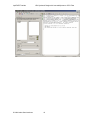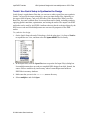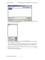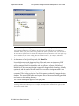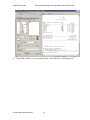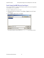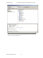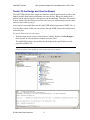
1
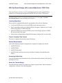
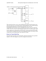
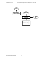
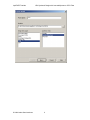
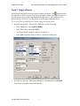
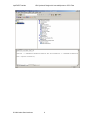
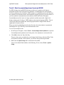
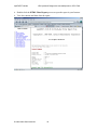
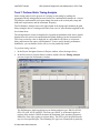
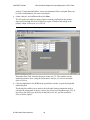
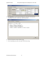
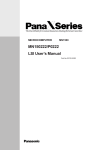
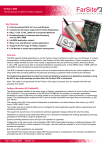
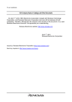
ispLEVER Tutorials
HDL Synthesis Design with
LeonardoSpectrum: CPLD Flow
Table of Contents
HDL Synthesis Design with LeonardoSpectrum: CPLD Flow ............................... 2
Task 1: Create a New Project ............................................................................... 5
Task 2: Target a Device........................................................................................ 7
Task 3: Start LeonardoSpectrum from ispLEVER................................................. 9
Task 4: Use Quick Setup to Synthesize the Design............................................ 11
Task 5: Import the EDIF File into Your Project.................................................... 15
Task 6: Fit the Design and View the Report........................................................ 17
Task 7: Perform Static Timing Analysis .............................................................. 19
Summary ............................................................................................................ 22
Glossary.............................................................................................................. 23
Recommended Reference Materials................................................................... 24
© 2004 Lattice Semiconductor
Tutor3
ispLEVER Tutorials
HDL Synthesis Design with LeonardoSpectrum: CPLD Flow
HDL Synthesis Design with LeonardoSpectrum: CPLD Flow
This tutorial shows you how to use LeonardoSpectrum from within ispLEVER® to
synthesize a Verilog design and generate an EDIF file for a Lattice CPLD device.
Note: If you want to learn how to use LeonardoSpectrum in standalone mode or understand more about
its advanced features, please see the third-party manuals online by choosing Help > ispLEVER
Documentation Library from the ispLEVER Project Navigator.
Learning Objectives
When you have completed this tutorial, you should be able to do the following:
•
Create a new EDIF project in the ispLEVER system and target a device.
•
Start LeonardoSpectrum from within the Project Navigator, synthesize your Verilog
design, and generate an EDIF netlist file.
•
Import the EDIF file into the ispLEVER system, fit the design, generate a JEDEC
file, and view the Fitter report.
•
Perform static timing analysis using the Performance Analyst and view the results.
Time to Complete This Tutorial
The time to complete this tutorial is about 20 minutes.
System Requirements
One of the following software configurations is required to complete the tutorial:
•
IspLEVER Starter
•
ispLEVER Base
•
ispLEVER Advanced
•
ispLEVER Advanced System with active Mentor Graphics LeonardoSpectrum
license
Accessing Online Help
You can find online help information on any tool included in the tutorial at any time by
pressing the F1 key.
About the Tutorial Design
The tutorial design consists of a simple set of equal-to, greater-than, and less-than data
comparators, as shown in the following figure:
© 2004 Lattice Semiconductor
2
ispLEVER Tutorials
HDL Synthesis Design with LeonardoSpectrum: CPLD Flow
This tutorial first directs you to create an EDIF project in the Project Navigator, then
select the target device in which the design will be implemented. The tutorial assumes
that functional simulation has already been performed. Next, you start
LeonardoSpectrum and open a new LeonardoSpectrum project. After you import the
VHDL source files and set the implementation options, the tool synthesizes the design
into the target device and generates an EDIF netlist.You then import the EDIF netlist
into the Project Navigator project and perform mapping, placing, and routing. Finally,
you perform a static timing analysis and examine the results.
About the Tutorial Data Flow
The following figure illustrates the design flow that the tutorial takes.You may find it
helpful to refer to this diagram as you move through the tutorial tasks.
© 2004 Lattice Semiconductor
3
ispLEVER Tutorials
HDL Synthesis Design with LeonardoSpectrum: CPLD Flow
multiple.v
Synthesize with
Leonardo-Spectrum
multiple.edf
Fit design
with Fitter
Analyze timing with
Performance Analyst
© 2004 Lattice Semiconductor
4
JEDEC
file
ispLEVER Tutorials
HDL Synthesis Design with LeonardoSpectrum: CPLD Flow
Task 1: Create a New Project
To begin a new project, you must create a project directory. Then you must give the
project file a name (.syn) and declare the project type (EDIF).
The ispLEVER software saves an initial design file with the .syn file extension in the
directory that you specify. All project files are copied to or created in this directory. The
project type specifies that all design sources will be of this type.
To create a new project:
1. Start the ispLEVER system, if it is not already running.
2. In the Project Navigator, choose File > New Project to open the Create New Project
dialog box.
3. In the dialog box, do the following:
•
In the Project Name box, type mux.
•
In the Location box, change to the following directory:
<install_path>\examples\tutorial\tutor3.
Note: If you want to preserve the original tutorial design files, save the tutor3 directory to
another location on your computer before proceeding.
•
In the Design Entry Type box, choose EDIF.
•
In the Synthesis Tools box, choose LeonardoSpectrum.
•
Click Next to open the Project Wizard – Select Device dialog box.
© 2004 Lattice Semiconductor
5
ispLEVER Tutorials
© 2004 Lattice Semiconductor
HDL Synthesis Design with LeonardoSpectrum: CPLD Flow
6
ispLEVER Tutorials
HDL Synthesis Design with LeonardoSpectrum: CPLD Flow
Task 2: Target a Device
In the Project Navigator Sources in Project window, the device icon
appears next to
the target device for the project. The Project Navigator enables you target a design to a
specific Lattice device at any time during the design process. The default device is
ispLSI5256VE-165LF256. For this project, you will target a different device.
To view the list of available devices and to change the target device:
1. In the Project Wizard – Select Device dialog box, do the following:
•
In the Family box, select ispMACH4000.
•
In the Device box, choose LC4256V.
•
Accept the default settings for the rest of the boxes.
•
Click Next to open the Project Wizard – Add Source dialog box.
2. In the Project Wizard – Add Source dialog box, click Next, then click Finish.
Your Project Navigator should look like this:
© 2004 Lattice Semiconductor
7
ispLEVER Tutorials
© 2004 Lattice Semiconductor
HDL Synthesis Design with LeonardoSpectrum: CPLD Flow
8
ispLEVER Tutorials
HDL Synthesis Design with LeonardoSpectrum: CPLD Flow
Task 3: Start LeonardoSpectrum from ispLEVER
For HDL designs, the ispLEVER software provides two synthesis tools that are
integrated into the Project Navigator environment: LeonardoSpectrum and Synplify.
You can synthesize your Verilog or VHDL design as a standalone process by choosing
the synthesis tool from the Lattice Semiconductor program group in your Start menu, or
you can synthesize automatically and seamlessly within the Project Navigator.
LeonardoSpectrum for Lattice is a logic synthesis tool that starts with a high-level
design written in the Verilog or VHDL hardware description language (HDL). Then it
converts the HDL description into small, high-performance design netlists that are
optimized for Lattice devices.
When you start LeonardoSpectrum for the first time, the main window is maximized
and displays the Tip of the Day and an information screen.
To start LeonardoSpectrum:
1. In the Project Navigator, choose Tools > LeonardoSpectrum Synthesis to open the
LeonardoSpectrum synthesis tool. It may take a few moments to activate the tool.
2. Click OK to close the Tip of the Day.
There are three ways to synthesize your design: Quick Setup, Advanced Flow Tabs,
and Synthesis Wizard. In this tutorial, you will use the Quick Setup method.
3. Make sure the Quick Setup tab is selected on the toolbar.
Your screen should look similar to the following. If not, choose Tools > Quick
Setup.
© 2004 Lattice Semiconductor
9
ispLEVER Tutorials
© 2004 Lattice Semiconductor
HDL Synthesis Design with LeonardoSpectrum: CPLD Flow
10
ispLEVER Tutorials
HDL Synthesis Design with LeonardoSpectrum: CPLD Flow
Task 4: Use Quick Setup to Synthesize the Design
Quick Setup is a push-button flow that you can use to achieve good first-pass synthesis
results. You specify the target technology, open your input design files, optionally set
the target clock frequency, and verify the name of the output netlist. When you click
Run Flow, the entire synthesis flow is executed from start to finish, including synthesis,
applying global constraints, optimization, and writing the netlist. The output is an EDIF
netlist that can be read by ispLEVER. Attributes that are placed on design objects by the
HDL source code and LeonardoSpectrum are converted to properties in the EDIF
netlist.
To synthesize the design:
1. On the Quick Setup tab under Technology, click the plus sign (+) in front of Lattice
to expand the tree view, and then select the ispmach4000V device family.
2. In the Input field, click the Open files icon to open the Set Input File(s) dialog box.
LeonardoSpectrum does not read pre-compiled HDL designs from disk. Instead, the
source files are read directly into memory where LeonardoSpectrum builds an
EDIF-like in-memory database.
3. Make sure that you are in the tutorial\tutor3 directory.
4. Select multiple.v and click Open.
© 2004 Lattice Semiconductor
11
ispLEVER Tutorials
HDL Synthesis Design with LeonardoSpectrum: CPLD Flow
LeonardoSpectrum automatically points the output file to the project directory and
places the file name in the Input box.
5. Directly below the Open Files icon, click the Working Directory icon to open the
Set Working Directory dialog box.
The working directory is where LeonardoSpectrum places all generated output files.
These files include the output files from the synthesis process. For ispLEVER
projects, you should make the working directory the same as your project directory.
6. Make sure the path is pointing to <install_path>\examples\tutorial\tutor3,
then click Set to close the dialog box.
© 2004 Lattice Semiconductor
12
ispLEVER Tutorials
HDL Synthesis Design with LeonardoSpectrum: CPLD Flow
Note: Only a few files will be generated in this tutorial. Because many generated files can be
created in a real project, it is a good practice to separate your design source files and batch scripts
into a separate subdirectory. For example, the input source files could be kept in a subdirectory
named src. Then, if your first synthesis run generates the "fastest" possible circuit, you may want to
do one or more optional runs to evaluate the tradeoffs between speed and area. You can simply copy
the src subdirectory into a new working directory named "smallest,” for example, and the new
generated files for the next run will be placed there.
7. At the bottom of the Quick Setup tab, click Run Flow.
LeonardoSpectrum reads the opened input files and creates an in-memory EDIF
style database called the RTL database. The design is composed of generic gates
and non-mapped (black box) modules such as operators, counters, and inferred
RAMs. Next, the in-memory design is mapped to the specified technology, globally
optimized, and the results for each module are saved. If a timing constraint is not
met at this point, additional critical-path optimizations are run to try to meet the
constraints. The results are kept in a second in-memory technology-mapped design
database. The output EDIF netlist and support files are then automatically generated
and written to the working directory.
The Critical Path Report appears in the right pane.
Note: The Run Flow button is not active until you have selected your Input File(s) and target
technology. When the synthesis process is complete, the Information window on the right says that
the run successfully ended.
© 2004 Lattice Semiconductor
13
ispLEVER Tutorials
HDL Synthesis Design with LeonardoSpectrum: CPLD Flow
8. Choose File > Exit to exit LeonardoSpectrum. Click Yes in the confirmation box.
© 2004 Lattice Semiconductor
14
ispLEVER Tutorials
HDL Synthesis Design with LeonardoSpectrum: CPLD Flow
Task 5: Import the EDIF File into Your Project
You can import EDIF 2 0 0 netlists from third-party synthesis tools, such as Synplify or
LeonardoSpectrum, into ispLEVER.
To import an EDIF netlist into your project:
9. In the ispLEVER Project Navigator, choose Source > Import to open the Import
File dialog box.
10. Select multiple_0.edf, and then click Open.
The software adds the selected EDIF file (multiple_0.edf) to the project sources.
© 2004 Lattice Semiconductor
15
ispLEVER Tutorials
HDL Synthesis Design with LeonardoSpectrum: CPLD Flow
Note: After you import an EDIF file into the ispLEVER project, it is always linked to the Project
Navigator. Therefore, if you make changes and recompile your HDL file to create a new EDIF file,
your project is automatically updated as well.
© 2004 Lattice Semiconductor
16
ispLEVER Tutorials
HDL Synthesis Design with LeonardoSpectrum: CPLD Flow
Task 6: Fit the Design and View the Report
The ispLEVER software has a single user interface with all options preset to deliver the
highest possible push-button performance for most devices. When you double-click a
process, all the processes prior to that process run automatically. Therefore, all you have
to do is double-click the final process. However, here you will run one process at a time
and view the results as you go.
At the end of a successful fitter run, the ispLEVER software generates a JEDEC file, as
well as a fitter report, so that you can see how the ispLEVER software has utilized and
routed the part.
To run the Fitter and view the report:
1. With the target device selected in the Sources window, double-click Fit Design in
the Processes for Current Source window to run the Fitter.
The ispLEVER software successfully fits the design in the specified device and
generates a JEDEC file.
Optional: If you like, you can right-click on the JEDEC File process and select View to create and
look at the contents of the JEDEC file. Close the file when you are through.
© 2004 Lattice Semiconductor
17
ispLEVER Tutorials
HDL Synthesis Design with LeonardoSpectrum: CPLD Flow
2. Double-click the HTML Fitter Report process to open the report in your browser.
3. View the contents and then close the report.
© 2004 Lattice Semiconductor
18
ispLEVER Tutorials
HDL Synthesis Design with LeonardoSpectrum: CPLD Flow
Task 7: Perform Static Timing Analysis
Static timing analysis is the process of verifying circuit timing by totaling the
propagation delays along paths between clocked or combinational elements in a circuit.
The analysis can determine and report timing data such as the critical path, setup and
hold-time requirements, and the maximum frequency.
The Performance Analyst traces each logical path in the design and calculates the path
delays using the device’s timing model and worst-case AC specifications supplied in the
device data sheet.
The timing analysis results are displayed in a graphical spreadsheet with source signals
displayed on the vertical axis and destination signals displayed on the horizontal axis.
The worst-case delay value is displayed in a spreadsheet cell if there is at least one
delay path between the source and destination. To more easily identify performance
bottlenecks, you can double-click a cell to view the path delay details.
To perform timing analysis:
1. In the Project Navigator Sources in Project window, select the target device.
2. In the Processes for Current Source window, double-click the Timing Analysis
process to open the Performance Analyst.
The Performance Analyst performs seven distinct analysis types: fMAX, tSU/tH,
tPD, tCO, tOE, tCOE, and tP2P. The first type, fMAX, is an internal register-toregister delay analysis. fMAX measures the maximum clock operating frequency,
limited by worst-case register-to-register delay. The tP2P type is the path between
any two user-specified pins. The remaining five types are external pin-to-pin delay
© 2004 Lattice Semiconductor
19
ispLEVER Tutorials
HDL Synthesis Design with LeonardoSpectrum: CPLD Flow
analysis. Timing threshold filters, source and destination filters, and path filters can
be used to independently fine-tune each analysis.
3. Under Analysis, select tCO and then click Run.
The tCO path trace analysis reports clock-to-out delay starting from the primary
input, going through the clock of flip-flops or gate of latches, and ending at the
primary output. In this case, it is 12.95 ns.
Note: Your timing results may differ slightly.
Remember from Task 4 that the data arrival time was 7.0. This number was the
simulated estimate. Now, using the Performance Analyst, you can see the actual
delay of 9.64 ns.
4. Click the highlighted cell (12.95) in the spreadsheet window to open the Expanded
Path dialog box.
This dialog box enables you to analyze the individual timing components used to
calculate the timing path. It shows a source pin (From) and a destination pin (To). It
also shows the delay type, the delay of that path (value ns), and the cumulative
delay of all the signals.
© 2004 Lattice Semiconductor
20
ispLEVER Tutorials
HDL Synthesis Design with LeonardoSpectrum: CPLD Flow
5. Click Equations to open the Equations dialog box, which shows the functional
relationship between the selected source and the destination.
6. Close the Performance Analyst without saving.
7. Close LeonardoSpectrum, then close ispLEVER without saving.
© 2004 Lattice Semiconductor
21
ispLEVER Tutorials
HDL Synthesis Design with LeonardoSpectrum: CPLD Flow
Summary
You have completed the HDL Synthesis Design with LeonardoSpectrum tutorial. In this
tutorial you have learned how to do the following:
•
Create a new EDIF project in the ispLEVER system and target a device.
•
Launch LeonardoSpectrum from within ispLEVER and generate an EDIF netlist file
using the Quick Setup tab flow.
•
Import the EDIF file into the ispLEVER system, fit the design, generate a JEDEC
file, and view the Fitter report.
•
Run static timing analysis using the Performance Analyst and view the results.
© 2004 Lattice Semiconductor
22
ispLEVER Tutorials
HDL Synthesis Design with LeonardoSpectrum: CPLD Flow
Glossary
Following are the the terms and concepts that you should understand to use this tutorial
effectively.
EDIF. EDIF (Electronic Design Interchange Format) is a format used to exchange design data between
different electronic computer-aided design systems. It is designed to be written and read by computer
programs that are constituent parts of EDA systems or tools. Its syntax has been designed for easy machine
parsing and is similar to LISP. The ispLEVER software supports EDIF Version 2 0 0.
HDL. An HDL is a hardware description language, which describes the structure and function of integrated
circuits.
static timing analysis. Static timing analysis is the process of verifying circuit timing by totaling the
propagation delays along paths between clocked or combinational elements in a circuit. The analysis can
determine and report timing data such as the critical path, setup and hold-time requirements, and the
maximum frequency
synthesis. Synthesis is the process of translating a high-level design (RTL) description consisting of state
machines, truth tables, and/or Boolean equations into a process-specific gate-level logic implementation.
VHDL. VHDL (or VHSIC (Very High-Speed Integrated Circuits) Hardware Description Language) is a
language for describing the structure and function of integrated circuits.
Verilog. Verilog is a language for describing the structure and function of integrated circuits.
© 2004 Lattice Semiconductor
23
ispLEVER Tutorials
HDL Synthesis Design with LeonardoSpectrum: CPLD Flow
Recommended Reference Materials
You can find additional information on the subjects covered by this tutorial from the
following recommended sources:
•
LeonardoSpectrum for Lattice User’s Manual
•
LeonardoSpectrum for Lattice HDL Synthesis Manual
•
Lattice ispLEVER online help:
•
•
How To guides
•
Process Flows > ispXPGA Flows
Data sheets, technical notes, and other information on ispXPGAs on the Lattice
Web site at http://www.latticesemi.com/search/literature.cfm. Click on FPGA >
ispXPGA.
© 2004 Lattice Semiconductor
24