1
8. Connectors and Pinouts
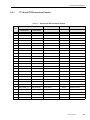
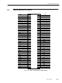
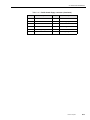
Table 8-7. VMEbus P1 connector description (system board). (Continued)
8.3.1
Pin #
Row A
Row B
Row C
22
Connected to A21
(IACKIN=IACKOUT)
NC
NC
23
NC
GND
NC
24
NC
GND
NC
25
NC
NC
NC
26
NC
NC
NC
27
NC
NC
NC
28
NC
NC
NC
29
NC
NC
NC
30
NC
NC
NC
31
NC
NC
+12V
32
+5V
+5V
+5V
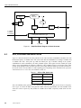
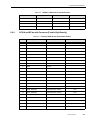
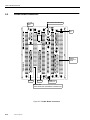
VMEbus P2 Connector (System Board)
The VMEbus P2 Connector accommodates user-defined signals on row A and C. The optional paddleboard is
one way of easily accessing the USP-2 VMEbus P2 Connector user-defined signals.
.
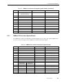
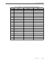
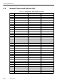
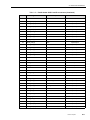
Table 8-8. VMEbus P2 connector description (system board)
Pin #
Row A
Row B
Row C
1
+5V
+5V
+5V
2
GND
GND
GND
3
NC
NC
SCSIB_TRMPWR
4
GND
NC
SCSIB_ATN_L
5
+5V
NC
SCSIB_BSY_L
6
+5V
NC
SCSIB_ACK_L
7
+5V
NC
SCSIB_RST_L
8
NC
NC
SCSIB_MSG_L
Parallel Port
Floppy Port
9
PP_STRB_L
NC
NC
SCSIB_SEL_L
10
PP_ACK_L
FD_DEN_SEL
NC
SCSIB_CD_L
11
PP_BUSY
FD_INDEX
NC
SCSIB_REQ_L
12
PP_PE
FD_MOT_EN
GND
SCSIB_IO_L
13
PP_ERROR_L
FD_DRV_SEL
+5V
SCSIB_DAT(0)
Themis Computer
8-9