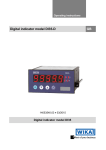
1
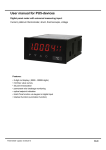
User manual for PZ5 devices
Digital processor controlled arithmetic panel meter:
Two measuring inputs with calculation:
x = (In1 + In2)
*K
x = (In1 - In2)
*K
x = (In1 * In2)
*K
x = (In1 / In2)
*K
x = (In1 * 100 / In2)
*K
Technical features:
• display from -9999…99999
• MIN / MAX value recording
• 30 points linearisation per channel
• permanent cable breakage monitoring
• optical setpoint display
• Hold- /Tara-function via keypad or digital input
• configurable channel switching
96x48
Contents
1.
Identification…………………………………………………………………………..
2
2.
Technical data……………………………………………………………………...
3
3.
Safety advice……………………………………………………………………
5
4.
Assembly………………………………………………………………………………… 7
5.
Electrical connection……………………………………………………………......
6.
Operation and function description………………………………………………... 11
8
6.1 Operation………………………………………………………………………… 11
6.2 Alarms / Relay…………………………………………………………………… 15
6.3 Analog output…………………………………………………………………... 18
6.4 Digital input / ZERO-key…………………………………………………….
18
6.4.1 HOLD-Function…………………………………………………………… 18
6.4.2 TARA-Function…………………………………………………………… 18
6.4.3 Configurable channel switching ………………………………………
18
6.5 Interface RS232 / RS485……………………………………………………
19
7.
Programming………………………………………………………………………
20
8.
Program number description…………………………………………………..
27
8.1 Program number table………………………………………………………
32
9.
Error elimination………………………………………………………………………. 37
1
1. Identification
1. Identification
STANDARD TYPES
ORDER NUMBER
Supply 230 VAC
PZ5.0001.1540C
Supply 115 VAC
PZ5.0001.1440C
Supply 24 VDC
(galvanic insulated)
PZ5.0001.1740C
Options – breakdown of order code:
P Z
Basic type
5
0
0
0
1
1
5
4
0
C
Internal index
P
Standard device type
Two standard signal inputs
Setpoints
Z
Number of digits
5 digits
5
0
no setpoint
2
2 relay outputs
4
4 relay outputs
Interface
Mechanical options
no
0
1
IP65, foil key pad, screw
clamp
RS232
2
4
IP54, foil key pad, screw
clamp
RS232
(galvanic insulated)
3
7
IP65, foil key pad, plugin clamp
RS485
(galvanic insulated)
4
9
IP54, foil key pad, plugin clamp
Sensor supply
Supply voltage
no
0
4
115 VAC
10 V / 20 mA
2
5
230 VAC
24 V / 50 mA
3
7
24 VDC (galv. insulated)
Outputs
Housing size
no
0
0-10 V
1
0-20 mA
2
4-20 mA
3
1
96x48 mm
Measuring input
1
Please state physical unit by order, e.g. m/min.
2
Current, voltage
2. Technical data
2. Technical data
Housing
Dimensions
96x48x134 mm (BxHxD) including plug-in terminal
96x48x148 mm (BxHxD) including plug-in terminal
Panel cut-out
92.0+0.8 x 45.0+0.6 mm
Wall thickness
from 0 up to 50 mm
Fixing
snap-in screw element
Material
PC / ABS-Blend, black, UL94V-0
Protection class
standard IP54 (Front), IP00 (Back side)
Weight
ca. 450 g
Connection
Srew clamp / plug-in terminal; line cross section up to 2.5 mm2
Display
Digit height
14 mm
Segment colour
red
Range of display
-9999 to 99999
Setpoints
1 LED per setpoint
Overflow
horizontal bars at the top
Underflow
horizontal bars at the bottom
Display time
0.04 to 10 seconds
Input
Measuring range
0…10 V and 0/4…20 mA
Input resistance
0…10 V
RI = ~ 150 kΩ
0/4…20 mA
RI = ~ 50 Ω
Measuring error
at measuring time = 1 sec
0.02 % v. MB ± 1 Digit TU = 20…40°C
Temperature drift
at TU < 20°C bzw. > 40°C
all measuring inputs 50 ppm/K
Measuring time
1 channel 0.1…10.00 seconds
2 channels 0.2…10.00 seconds
Measuring principle
Sigma / Delta
Resolution
24 bit
Output
Relay
Switch-over contact
230 VAC / 5 A; 30 VDC / 2 A at ohm resistive load
Switching cycles
0.5 * 105 at max. contact load
5 * 106 mechanically
Separation as per DIN EN 50178 / characteristic data as per
DIN EN 60255
3
2. Technical data
Output
Analog output
0...10 V (12-bit) load ≥ 10 kΩ
0...20 mA (12-bit) load ≤500 Ω
4...20 mA (12-bit) load ≤500 Ω
Internal resistance
100 Ω at 0 - 10 VDC analog output
Error
0.1 % % in the range TU= 20...40°C, beyond 50 ppm/K
Sensor supply
(galvanic insulated)
10 VDC, 20 mA
24 VDC, 50 mA
Interface
Protocol
manufacturer-specific ASCII
RS232
(optionally galv.insulated)
9600 Baud, no parity, 8 databits, 1 stopbit , ASCII protocol
Lead length
max. 3 m
RS485 (galv. insulated)
9600 Baud, no parity, 8 databits, 1 stopbit , ASCII protocol
Lead length
max. 1000 m
Power Pack
Supply voltage
(galvanic insulated)
230 VAC / 50/60 Hz / ±10 %
115 VAC / 50/60 Hz / ±10 %
24 VDC / ±10 %
Power consumption
max. 15 VA
Memory
Parameter memory EEPROM
Data life
>100 years
Ambient conditions
Working temperature
0...60 °C
Storing temperature
-20...80 °C
Climatic density
rel. humidity ≤75 % on years average without dew
EMV
DIN 61326
CE-sign
conformity to 89/336/EWG
Safety standard
DIN 61010
4
3. Safety advices
3. Safety advices
Please read the users guide and chapter 4 before installation and keep it for future
reference.
Proper use
The PZ5 is designed for the evaluation and display of transmitter signals (standard signals).
With the set points, it is possible to perform simple control tasks .
Caution! Careless use or improper operation can result in personal
injury and/or damage to the equipment!
Control of the device
The panel meters are checked before dispatch and sent out in perfect condition. Should
there be any visible damage, we recommend close examination of the packaging. Please
inform the supplier immediately of any damage .
Installation
The PZ5 must be installed by a suitably qualified specialist (e.g. with a qualification in
industrial electronics) .
Notes on installation
There must be no magnetic or electric fields in the vicinity of the device, e.g. due to
transformers, mobile phones or electrostatic discharge.
The fuse rating of the supply voltage should not exceed a value of 6A N.B. fuse.
Do not install inductive consumers (relays, solenoid valves etc.) near the device
and suppress any interference with the aid of RC spark extinguishing combinations
or free-wheeling diodes.
Keep input, output and supply lines separate from one another and do not lay them
parallel with each other. Position “go” and “return lines” next to one another. Where
possible use twisted pair. So, you receive best measuring results.
Screen off and twist sensor lines. Do not lay current-carrying lines in the vicinity.
Connect the screening on one side on a suitable potential equaliser (normally
signal ground).
The device is not suitable for installation in areas where there is a risk of explosion.
Any electrical connection deviating from the connection diagram can endanger
human life and/or can destroy the equipment.
5
3. Safety advices
Do not install several devices immediately above one another or in an extremely
thermal isolated housing. Due to the internal heat dissipation of the decives, the
recommended ambient temperature can be excessed.
The terminal area of the devices is part of the service. Here electrostatic discharge
needs to be avoided. Attention! High voltages can cause dangerous body currents.
Galvanic insulated potentials within one complex need to be placed on a appropriate
point (normally earth or machines ground). So, a lower disturbance sensibility against
impacted energy can be reached and dangerous potentials, that can occur on long lines
or due to faulty wiring, can be avoided.
6
4. Assembly
4. Assembly
Type
Front frame
Panel cut out
(BxH) in mm
Assembly grid
horizontally
Assembly grid
vertically
96x48 mm
92.0+0.8 x 45.00 +0.6
120 mm (recommended)
96 mm (recommended)
7
5. Electrical connection
5. Electrical connection
8
5. Electrical connection
Interface connection
The lines for the RS232 interface must be connected 1:1, TxD to TxD und RxD to RxD.
Connection pattern PC or SPS ⇔ PZ5
The interface RS485 is connected via a screened data line with twisted wires
(Twisted-Pair). A termination of the bus wire musst be connected at the end of each bus
segments. This is neccessary to guarantee a safe data transfer on the Bus. Therefor a
resistance (120 Ohm) is inserted between the wires Data B (+) and Data A (–).
Caution!
The potential reference can lead to a compensating current
(interface ⇔ measuring input) with a non-galvanic insulated interface and can thus affect
the measuring signals.
Data A(-)
Data B(+)
41
42
43
Device 1
9
120 Ohm
Termination
5. Electrical connection
Connection examples
This section gives a few examples of practical connections. Other connection options can
be combined from the various examples
Co-channel measuremtn with current signals, supply 230 VAC:
Co-channel measuremtn with voltage signals, supply 24 VDC:
One-channel measurement with current signal in combination with digital input and sensor
supply, voltage supply 230 VAC:
10
6. Operation and function description
6. Operation and function description
6.1. Operation
Display (1)
7 segment display
5-digit, red
Digit height
14 mm
Display range
-9999…99999
Decimal points
none, 1, 2, 3, 4 (adjustable)
Setpoint displays (2)
Optical threshold message
4 LED, red
Keys (6), (7), (8), and (3)
Programming mode
Increase of value range
Decrease of value range
+
Address
Next lower program number
+
Address
Next higher program number
Activation of TARA or HOLD, Reset for MIN/MAX permanent
Dimension gap (4) for physical unit
Variable dimension strip
Dimension on demand e.g. kg, m³…
11
6. Operation and function description
Switching on
Before switching on, check all the electrical connections to make sure they are correct. On
completion of the installation, the device can be switched on by applying the supply voltage.
Starting sequence
During the switching-on process, a segment test is performed for approx. 1 second, whereby
all LED on the front (including setpoint LED) are triggered. After this, the type of software is
indicated for approx. 1 second and then, also for 1 second, the software version. After the
starting procedure, the unit changes to operation/display mode.
MIN-/MAX memory
The measured minimum and maximum values are saved in a volatile memory in the unit and
get lost when the unit is switched off.
You can call up the contents of the memory by pushing (less than 1 second) the [▲] or [▼]
key. The relevant value is indicated for approx. 7 seconds. By briefly pressing the same key
again, you will return immediately to the display mode.
▲ ⇒ Display of MAX value
▼ ⇒ Display MIN value
You can erase the value shown in the display by simultaneously operating the [▲] and [▼]
keys. The erasure is acknowledged by horizontal bars. The content of the memory will be
lost with switching-off of the device.
Display switch-over between two input channels
For the PZ5 device it is possible to swith temporarily between the different channels via
keypad. Push the [▼] - or [▲]-key for longer then 1 second, this leads to a switch-over to the
next channel. The channels can be run through forwards with key [▲] or backwards with
key [▼].
Display:
Channel 1
Channel 2
Arithmetic
Channel 1
Ch1
Ch2
Ar
Ch1
and so on...
Example:
Under program number (PN15≥3) the calculation (Ar) is parametrised as a permantent
display. The input value for channel 1 shall be displayed:
Push the [▲] key for at least one second. The PZ5 device acknowledges the change to
channel 1 by shortly displaying Ch1, thereupon you can stop pushing the key. The input
value of channel 1 is shown for approx. 7 seconds in the display, then the display changes
back to the parametrised display (arithmetic Ar). This operation is confirmed by „Ar“ in the
display. To recall all channels, the key [▲] or [▼] needs to be detached in the meantime.
12
6. Operation and function description
Overflow/Underflow of the arthmetic result
During the channel calculation the comma (PN18) is included in the calculation as decimal
point. Each over- or underflow of a channel leads in the calculation to a defined display.
This defined setting ensures that the corresponding set points go into a defined state.
Formula
Channel 1
Channel 2
Result
(Channel 1 + Channel 2) * Contant
Overflow
OK or overflow
Overflow
(Channel 1 + Channel 2) * Contant
Underflow
OK or underflow
Underflow
(Channel 1 + Channel 2) * Contant
OK or overflow
Overflow
Overflow
(Channel 1 + Channel 2) * Contant
OK or underflow
Underflow
Underflow
(Channel 1 + Channel 2) * Contant
Overflow
Underflow
Overflow
(Channel 1 – Channel 2) * Contant
Overflow
OK or underflow
Overflow
(Channel 1 – Channel 2) * Contant
Underflow
OK or overflow
Underflow
(Channel 1 – Channel 2) * Contant
OK or overflow
Underflow
Overflow
(Channel 1 – Channel 2) * Contant
OK or underflow
Overflow
Underflow
(Channel 1 – Channel 2) * Contant
Underflow/Overflow
Underflow/Overflow
Overflow
(Channel 1 * Channel 2) * Contant
Overflow
OK or overflow
Overflow
(Channel 1 * Channel 2) * Contant
Underflow
OK or underflow
Underflow
(Channel 1 * Channel 2) * Contant
OK or overflow
Overflow
Overflow
(Channel 1 * Channel 2) * Contant
OK or underflow
Underflow
Underflow
(Channel 1 * Channel 2) * Contant
Overflow
Underflow
Overflow
(Channel 1 / Channel 2) * Contant
Overflow
Optional
Overflow
(Channel 1 / Channel 2) * Contant
Underflow
Optional
Underflow
(Channel 1 / Channel 2) * Contant
OK
Overflow
Underflow
(Channel 1 / Channel 2) * Contant
OK
Underflow
Underflow
(Channel 1 * 100 / Channel 2)
Overflow
Optional
Overflow
(Channel 1 * 100 / Channel 2)
Underflow
Optional
Underflow
(Channel 1 * 100 / Channel 2)
OK
Overflow
Underflow
(Channel 1 * 100 / Channel 2)
OK
Underflow
Underflow
Overflow / Underflow
Overflow
horizontal bars are displayed on the top of the display
Underflow
horizontal bars are displayed at the bottom of the display
13
6. Operation and function description
6.2 Alarms / Relays
An active relay, or an activated setpoint is indicated by a flashing of the relevant
setpoint LED, which you find directly next to the 7-segment display.
Functional principle of alarms / relays
Alarm / Relay X
Channel 1, Channel 2, arithmetic calculation
Threshold
Switch-over threshold value
Hysterisis
Width of window between switching threshold
Working principle
Operating current / quiescent current
Switch-on delay
Time between reaching the threshold and the resultant
switching on of the relay.
Swith-off delay
Time between reaching the threshold and the resultant
switching off of the relay.
Alarm confirmation
Switch-on or switch-off interlock and rejection at activated
digital input or zero key
14
6. Operation and function description
Operating current
Relays S1-S4 are off
below the threshold and on
on reaching the threshold.
Quiescent current
Relays S1-S4 are on below
the threshold and switched off
on reaching the threshold.
Swith-on delay
The relay S1-S4 is on
10 seconds after reaching
the threshold; briefly
exceeding the threshold
does not lead to the relay
being switched on. The
switch-off delay functions
in a similar manner, in
other words it keeps the
set point switched on until
the parameterised time has
elapsed.
15
6. Operation and function description
Allocation of the alarms to a certain actuate value
As it is not always desired that alarms follow the operating mode, the outputs can be
assigned to the minimal-/maximal value or any other value. Therefor the adjustable value
range is assigned to the according program number (PN60, PN70, PN80 and PN90).
Alarms 1-4
Mode
Actuate value
0
none
1
Channel 1
2
Channel 2
3
Arithmetic function
Optical response, flashing display
If one or some thresholds are broken, the flashing of the alarm LED can amplify the optical
response by assignment of the threshold PN59 to the 7 segment display.
Example:
The threshold for flashing of the display is set at setpoint 2.
If setpoint 1 is exceeded and set point 2 is not, the setpoint LED 1 lights up permanently.
If setpoint 2 exceeds the threshold, the 7-segment display will start to flash, setpoint 1 will
light up permanently and set point LED 2 will flash.
The flashing enhances the optical response and the operator sees immediately that an
important threshold has been exceeded with this unit.
16
6. Operation and function description
6.3 Analogausgang
The optional analogue output is used for the transduction of a measuring value, supported
by a standard signal of 0…10 V or 0/4…20 mA. The analogue output is paramerterised via
the two program numbers PN20 final value (fullscale) and PN21 initial value (Offset). At
the initial value, the value is set at which the analogue output transmits the minimal value
(0 V or 0/4 mA) , and at the final value, the value at which the output transmits its
maximum (10 V or 20 mA).
By this means it is possible to re-scale the input signal of a transducer or even to convert it
into another standard signal. The analogue output can be set on channel 1, channel 2 or
the arithmetic value via the actuate value PN22. The analogue output is updated within the
cycle of the measuring time. At a high measuring rate, smaller cycle fluctuations of some
milli-seconds are possible.
6.4. Digital input / Zero key
In combination with the digital input (via terminal) and/or the zero key at the front,
functions like e.g. HOLD, TARA or a channel switch-over, can be actuated. The digital
input is available in combination with the option sensor supply or via an external 24 VDCsignal. The zero key at the front of the device can be activated by keypress.
6.4.1 HOLD function
The HOLD function is a static or keyed signal and is activated via the digital input or the
zero key. It always takes effect on the reference value that is allocated in the display.
With activated HOLD the lastly given measuring value remains and is by deactivation
permanently overwritten by the measuring value recording. With this function a test state
can be recorded beyond a specific period, so that this device can be used for control in
run production, too.
Advice: HOLD value gets lost with re-start!
6.4.2 TARA function
The TARA-Function can be activated by zero key or digital input and needs to last for at least
3 seconds.Thereby the instantaneous value of the channels is set on zero and the difference
to the actual value in PN4/PN9 (Offset displacement) is stored.This function is only done
once, after actuation of the desired trigger and has to be taken back bevor anew alignment.
The display reports this action by showing five little zeros in the display „ooooo“.
6.4.3 Configurable channel switch-over
The two input channels can be addressed via zero key, externally via the digital input or
time-controlled. This enables the user to see different measuring values in display change
mode under PN11.
17
6. Operation and function description
6.5. Interace RS232 / RS485
All PZ5 devices can optionally be programmed or configurated via an interface. Devices of
the basic type do not have an interface.
Operating mode
The interface can be operated in various modes that can be parameterised via the PN34
(Interface behaviour).
PN34=0
Standard mode in which the unit only replies if called on to do so. This mode is used only
for configuration. Furthermore the current measuring value can be recalled via commando
“A “.
PN34=1
Transmission mode in which the measurements are transmitted via the serial interface
cyclically with the set measuring time.
The transmission mode is interrupted on receipt of “> ↵“ and the unit changes to standard
mode. To change back to transmission mode, the display must be restarted, either by
entering the command “S ↵“ or by switching the device off and on.
With the transmission mode, the display value is transmitted via the interface in ASCII
format. Minus signs and decimal points are also transmitted so that the output can be
displayed directly on a terminal or processed by a SPS. Zeros at the front are suppressed
during transmission. With an over or underflow, the display transmits horizontal bars
(hyphens) "- - - - - ↵".
Examples:
"0.00 ↵" ; "-9.99 ↵" ; "999.99 ↵" ; "-123.45" ; "- - - - - ↵“
With the aid of this simple protocol structure, the display data can be transferred very
easily to a PC etc. and further processed there. In the simplest case, a terminal program
from the operating system is sufficient to store the received data in a file .
Configuration of the device via interface
For configuration the set-up tool PM-Tool can be used. As the communication is a
straight point-to-point connection. The baud rate is set to 9600 baud, with 8 databits,
without parity and one stopbit .
Configuration is performed by transmitting ASCII symbols.
18
7. Programming
7. Programming
Functional diagram of programming via key pad
Call for program mode
Device jumps on the nervermost approved
program number.
Step 1
+
Change to the next program number
Program number is displayed.
or
Change/read the deposited parameters
in the program
Flashing of the least significant digit.
Step 2
or
Save parameter
shortly
Save the complete range of parameters
Step 3
1 second
After 7 sec without selection, device changes
autonomous in the operating mode.
Operating mode
19
7. Programming
Description of the program numbers
In the display, the program numbers (PN) are shown, right-justified, as a 3-digit number
with a P in front of them:
Display of e.g. program number 0
Programming procedure
The entire programming of the PZ5 is done by the steps described below.
Change to programming mode
Push the [P] key to change into programming mode. The unit goes to the lowest available
program number. If the programming lock is activated, the key must be pushed for at least
1 second.
Change between program numbers
To change between individual program numbers, hold the [P] key down and push the
[▲] key for changing to a higher program number or the [▼] key for changing to a lower
number. By keeping the keys pushed, e.g. [P] + [▲], the display will begin, after approx.
1 second, to automatically run through the program numbers.
Change to the parameter
Once the program number appears in the display, you can push the [▼] or [▲] key to
get to the parameters set for this program number. The currently stored parameters are
displayed.
In this case, it is 75,640
20
7. Programming
Changing a parameter
After changing to the parameter, the lowest digit of the respective parameter flashes on
the display. The value can be changed with the [▲] or [▼] key. To move to the next digit,
the [P] key must be briefly pushed. Once the highest digit has been set and confirmed
with [P], the lowest digit will begin to flash again.
Example:
The 0 is flashing this is the lowest digit and
asks if you want to change it. Let us assume
the figure is to be changed from 75,640 to
75,000.
Briefly push the [P] key to move to the next
digit. The 4 begins to flash. Change the figure
by pushing [▲] or [▼] to change the digit from 4
to 0. Briefly push the [P] key to move on to the
next digit. The 6 begins to flash. Change the
digit by pushing [▲] or [▼] to move the 6 to a 0.
Briefly push the [P] key to move to the next
digit. The 5 and 7 do not need to be changed.
Saving of parameters
All parameters must be acknowledged by the user by pushing the [P] key for one
second. The changed parameters are then taken over as the current operating
parameters and saved in the EEPROM.
This is confirmed by horizontal bars lighting up in the display.
All the newly entered data are confirmed by the unit. If no confirmation is received, the
relevant parameters have not been saved, e.g. confirmation of parameters:
Changing from programming to operating mode
If no key is pushed in the programming mode for about 7 seconds, the unit will return
automatically to operating mode. Before „SAVE“ will be displayed untill the next
measuring value is displayed.
21
7. Programming
Two measuring inputs with arithmetic function
The PZ5 is provided with two standard inputs, which can be allocated via different types
of arithmetic functions. The inputs need to be configurated, so the device works according
to the signal that was generated by the sensor. The adjustment of the parameter that
form the basis is done under PN0 and PN5.
Setting / Calibration of the measuring input
All devices are calibrated in the factory, whereby zero point and final value have been
saved for the various measuring ranges. Via terminal connections and the choice of the
measuring input under PN0, different types of input signals can be worked up.
Factory calibration current / voltage under PN0/PN5 = 1…3
For these parameters, scaled display values can be allocated to defined input values.
For the adjusted measuring range, the final valueand the zero point need to be
parametrised.
For parameterisation, no sensor signal has to be applied because stored values are
used..
To display a sensor signal of 4...20 mA, for example PN0/PN5 =3 has to be
parameterised.
Sensor calibration PN0/PN5 = 4/6
During sensor calibration the device is calibrated directly at the measuring section via the
sensor signal or a calibrator. Therefor the measuring signal of the setpoint needs to be
connected to the input of the device. Under PN1 (final value) and PN2 (zero point) the
related display value (SCALE) and the related sensor signal (InPUT) needs to be stored. The
sensor signal is measured by the factory parameter and displayed as current or voltage.
A measurement needs to be started by shortly pushing the [P] key. By this process with 2
setpoints the device is aligned at the measuring section. For further adjustments to the
characteristic line of the sensors, a linearisation can be activated.
Linearisation PN100 / PN140
The PZ5 offers the possibility to linearize, with up to 30 additional setpoints, non-linear
sensors for the display of the measuring values and their subsequent processing (analog
output).
The number of the desired setpoints is determined under PN100/PN140. Be aware of
chosing the right one, as it can lead to a malfunction of the device in case of no adjustment.
22
7. Programming
Approach to sensor calibration for e.g. channel 1
To program e.g. 5 setpoints, 5 needs to be entered under PN100. Subsequently, for each
of the calibration points, the measured variable must be applied to the unit and the
respective display value needs to be parametrised under program numbers PN101 –
PN105. The sensor signal needs to be parametrised strictly increasing. A distcance from at
least + 1 Digit to the previous display value should be kept. If not, a rejection in the form of
not receiving a memory report (- - - - -).
Our example shows the linearisation of a pressure transducer for 0-100 mbar with an
output of 0-20 mA and an nonlinear range between 0-75 mbar. The display value is
calculated from the known characteristic line of the transducer or determined empirically.
This means, at a pressure of 15 mbar the transducer supplies 3.3 mA instead of the
optimum value of 3.0 ma. As 20 mA of the display correspond with 100.0, 3.3 mA
correspond 16.5 bevor correction. To make this correction, enter 15.0 under setpoint
PN101.
Setpoint (PN)
Pressure
(mbar)
Output
transducer (mA)
Display bevor
correction
(IN)
Desired display
(OUT)
2
0
0.5
2.5
0.0
101
15
3.3
16.5
15.0
102
30
6.2
31.0
30.0
103
40
9.2
46.0
40.0
104
60
11.4
57.0
60.0
105
75
14.7
73.5
75.0
1
100
20.0
100.0
100.0
23
7. Programming
Approach to factory calibration PN0/PN5 > 0
During adjusted factory calibration, a linearisation can be preset, without applying to the
sensor signal. Here the desired number of channel setpoints needs to be entered under
PN100 / PN140, in order to allocate display values to a defined measuring signal. Starting
on setpoint PN101 the display value (Scale) and subsequent the corresponding measuring
signal (Input) need to be programmed. Both actions are stored by pushing the P-key (for
approx. 1 second).
Input channels and Offset
The PZ5 device has two input channels, where standard signals (optionally 0...10 V,
0...20 mA or 4...20 mA) can be connected. Different signals can be collected for input
signals, e.g. channel 1 collects voltage and channel 2 collects current. For each channel
an arbitrarily measuring range can be set.
The offset displacement can be adjusted for each channel with PN4 and PN9. Thus an
irregularity of the accuracy or drifts of sensors can be balanced.
Two channel measurement with calculation
The measurement happens in an alternating process, during this process it will be
switched between the set measuring time and the two input channels. The time of the
particular indivdual measurement depends on the parametrised measuring time.
Afterwards the two ascertained values will be allocated in accordance to the in PN15
selected function, and the result will be displayed. The arithmetic functions of the device
are based on a floating-point arithmetic and include the parametrised comma in the
calculation.
Single channel measurement
A single channel measurement is done, if one of the measuring channels is selected as
display value via the PN15. In this case only the selected channel will be measured and
displayed. That way, the measuring time PN14 can be set on a smaller value (100 ms). If
200 ms was adjusted by a two channel measurement, then this value will not be changed.
If the PZ5 is parametrised on a one channel measurement, then the access to the
program numbers of the deactivated channels is not possible.
The channel, on which no measurement is done and the arithmetic result receive the
measuring/display value „0“ (Zero). Thereby setpoints or the analog output, which are
parametrised on these channels, are shifted to a defined state.
24
7. Programming
Arithmetic functions
With the PZ5 the measured values can be allocated with each other by different
mathematical functions.
For the following examples, the values of the channels and the constants are defined as
follows:
Channel 1 =
100,0
Channel 2 =
40,00
Constant
=
20
Display
=
xxxx,x
Addition
(Channel 1 + Channel 2) * Constant
With this function, the two scale signals are added and subsequently multiplied by a
constant.
Example: (100,0 + 40,00) * 20 = 2800,0
This function can be used to display inflow/outflow volumes, weighing technology, etc .
Subtraction (Channel 1 – Channel 2) * Constant
With this function, the difference from channel 2 to channel 1 is multiplied by a constant .
Example: (100,0 - 40,00) * 20 = 800,0
This function can be used to display differences etc.
Multiplication (Channel 1 * Channel 2) * Constant
With this function, the two scaled signals are multiplied with each other and then
multiplied by a constant.
Example: (100,0 * 40,00) * 20 = 80000,0
This function can be used to display power, energy etc.
Ratio
(Channel 1 / Channel 2) * Constant
With this function, the ratio is formed between the scaled signals of channel 1 and
channel 2 and then multiplied by a constant.
Example: (100,0 / 40,00) * 20 = 50,0
This function can be used to display mixing ratios etc .
Percent
(Channel 1 * 100 / Channel 2)
With this function, the scaled signal from channel 1 is multiplied by 100 and then divided
by the scaled signal from channel 2.
Example: (100,0 * 100) / 40,00 = 250,0
This function can be used to display a percentage ratio .
25
8. Program number description
8. Program number description
The PZ5 device has a default configuration ex factory, where sensor signals are changed
into a display value of 0…10000. At reset on default values should be done for devices,
where their pre-configuration is not known, (see chapter 9). Otherwise different
adjustments can cause an unwished behaviour of the device. These devices are
equipped with a digital input, by which functions like e.g. HOLD, TARA, Min/MAX can be
actuated.
Measuring input PN0/PN5
For basic configuration of the device, parametrise the suitable measuring input under
PN0/PN5. Possible input types are listet in the program number table (Chapter 8.1).
To assign characteristic lines into another device, use the settings 4/5 or 6 under
PN0/PN5.
Under this parameter setpoints are deposited as standardized values (Current, voltage)
and can be assigned by an optional interface into further devices.
Scaling of PN1/PN6 and PN2/PN7
PN1/PN6 and PN2/PN7 are used for the scaling of the device, with these two parameter,
final value (PN1/PN6) and zero point (PN2/PN7) are parametrised. For each setpoint
there is a SCALE–value and an InPUt–value. The SCALE–value indicates the desired display
value. By use of the InPUt–value, the related measuring signal is set. At factory calibration
the desired current or voltage value is preset. If sensor calibration is desired, a
measurement is actuacted by shortly pushing the [P]-key. Before, the stored current or
voltage value is displayed. All inputs need to be confirmed by pushing the [P]-key for
approx. 1 second; the device confirms this by showing 5 horizontal bars.
Position after decimal point PN3/PN8
By changing this parameter, the position of the comma in the display is changed.
Offset translation / Zero point translation PN4/PN9
With this parameter it is possible to do a parallel translation of the parametrised
characteristic line. This can be neccessary if e.g. a pressure sensor seasons by and by
and thus causes a zero point translation. With corresponding parametrisation, the sensor
can be adjusted on the zero point again. During offset translation, the original
characteristic line can be programmed by the user with help of PN1, PN2 or PN101...130,
or it can be the characteristic line of a temperature sensor. The value parametrised under
PN4 is added to the original display value. If e.g. a temperature sensor shows 0°C
instead of 3°C, you can compensate these irregularities by changing the value under PN4
from 0 to -3.
This parameter can be changed directly by taring, if it was acutated by the zero-key or
the digital input.
26
8. Program number description
Default display channel PN10
The PZ5 can be parametrised and displayed on any display channel, independent of the
calculation.
If the arithmetic function PN15 = 0 is deactivated, the channel value is set on zero.
Configurable channel switch-over PN11
This program number enables the user to see all measuring values of the channel and
the arithmetic function during standard operation.
Therefor all different types of operation like e.g. a static, keyed or automatic display
change are supported by the device.
Bevor each change of the channel, the device shows the name of the channel in the
display. For channel 1 it displays „Ch1“ and for channel 2 it displays „Ch2“. For the
arithmetic function it displays „Ar“, if it was activated by PN15 > 0.
The static and keyed channel swith-over can be triggered via the digital input or the fourth
key. The selection is done via program numbers PN53 and PN54.
At the static channel switch-over it is changed as long on the via PN11 selected channel
(PN11 = 1…3), as the related digital input or the zero-key is deactivated again.
At the keyed channel switch-over it is changed in the order “Ch1”, “Ch2” and optional “Ar”
at each actuation of the defined activator.
During the time-controlled automatic channel switch-over the display jumps from one
channel to the next following one during the preset time cycle (“Ch1”, Ch2” optional “Ar”).
If the arithmetic function is deactivated (PN15=0), the display only changes between the
two display values of channel 1 and channel 2.
Even at activated display change MIN-/MAX-values of the currently active display channel
can be recalled via [▲]- and [▼]-keys. The channel switch-over is delayed by the MIN/MAX-display time.
Display time PN13
Under display time the time is set, that shall pass between the update of the display. The
longer the time between two display cycles, the optically calmer seems the display,
whereas a display time of 1 second is found very pleasant.
27
8. Program number description
Measuring time PN14
The device always executes a two channel measurement. For a measuring interval
(adjustable via PN14) it is switched to and fro severable times between the input channels
and by the individual measurements per channel, a simple arithmetic average detemination
is used. The conversion time of the integrated AD-converter is aligned dynamically to the
measuring time.
Set measuring time / s
< 0.25
< 0.5
< 0.8
> 0.8
Conversion time / ms
approx. 30
approx. 30
approx. 30
approx. 30
The AD-converter is equipped with a digital filter function, which suppresses very effectively
a possible mains hum (50 Hz). To use this function, a measuring time from more than 0.5
seconds should be selected.
Arithmetic Function PN15
Under this function the calculation type of the channels is set. The different functions can
be seen in the program number table Chapter 8.1.
The arithmetic function is completely calculated in floating-point-arithmetic. Thereto the
scaled measuring values of both input channels are calculated and processed in floatingpoint-arithmetic, too. According to this the resolution of the single channels can be clearly
higher than the display value. For the calculation a bit mantissa and a 8 bit exponent are
used. For this reason the adjusted comma (PN3, PN8, PN17, PN18) need to be included
at the calculation.
CAUTION!
The outputs work only with the display value and reach especially at the optional
analog output only its resolution!
Zero point suppression PN18
At the zero point suppression, a value range around the zero point can be preset, so the
display shows a zero. The amount that is effective comparably in the positive as in the
negative range is parametrised in the program number. This can be neccessary if e.g. a
rotation speed is collected by an analog sensor and this sensor shows a drift around the
zero point. If the signal changes at idleness of the motor slightly, still a rotation speed of
„0“ is shown. Marginally negative rotation speeds are suppressed.
28
8. Program number description
Analog output PN20, PN21 and PN22
The parameter of the optional analog output apply to the scale of the device and are
cyclical updated with the measuring time. Via PN22 = 0 the analog output can be
deactivated, whereas it remains on its initial value after a re-start of the device.
The Analog output can be related to all other possible values that are collected in the
device. For further information please see Chapter 7 or the program number table in
Chapter 8.1.
Initial value and final value are always displayed without comma. This is always based in
the depiction of the measuring value in the display, this means at a depiction of e.g. 6.400
the final value can be parametrised by 6400 to this display value.
Interface behaviour PN34
The current display value can be sent via the optional interface. In standard operation
PN34 = 0 the display stays passive and expects data from the Bus. This operation is
suitable for the configuration of the device. At slowly processes the current measuring
value can be recalled actively via command. During sending mode PN34 = 1, the
current measuring value is sent actively by the device in the cycle of the measuring
time. Further information can be found in Chapter 7 / Operation mode.
Security settings / User level PN50 to PN52
The access to the program numbers is controlled by the security settings. The user has
only access to settings that were allowed by the plant operator, like e.g. the adjusment
of the alarm thresholds. The smaller the numerical value of the under PN52 preset user
level, the larger is the grade of the saving of the device parameter from user
interventions.
29
8. Program number description
User level PN52=
0
1
2
3
4
5
6
7
8
Access to:
PN
Display brightness
19
X
X
X
X
X
X
X
X
X
Programming lock
50
X
X
X
X
X
X
X
X
X
Serial number
200
X
X
X
X
X
X
X
X
X
Alarm threshold value
61, 71, 81, 91
X
X
X
X
X
X
X
X
Alarm parameter
59…95
X
X
X
X
X
X
X
Interface parameter (Option)
32…34
X
X
X
X
X
Analog output parameter (Option)
20…22
X
X
X
X
X
Measuring input parameter
0…18
X
X
X
Linearisation parameter for the
measuring input
100…170
X
X
X
Activation code
51
X
User level
52
The user level 1,3, 5 and 7 are reserved, at this parametrisation always the numeric
higher user level is active (2, 4, 6 und 8).
The user level adjusted under PN52 is activated, as long as the programming lock PN50
differs with the activation code PN51 on a value basis. For dispatch of the PZ5, both
parameter are set to the values 0000, by what the programming lock is deactivated.
To activate the adjusted user level, a 4-digit number needs to be entered as activation
code under PN51. It needs to be confirmed by pushing the [P] key for approx. 1 second.
During the change into program mode the device jumps to the first program number that
is available. If user level PN52 = 3 is parametrised, e.g. the access to the program
numbers of the alarms is approved, a change of the measuring input PN0 is not possible
for this setting.
To receive the access to all program numbers (PN52 = 0), the programming lock under
PN50 and the under PN51 stored 4-digit activation code need to be entered again and to
be acknowledged by pushing the [P] key for approx. 1 second. After this the access to all
program numbers is free.
Caution!
If the locking code got lost, the device can be reset to the default
value 0000 by the manufacturer, without any data loss.
30
8. Program number description
Digital input and/or zero key PN53, PN54
The digital input and the zero key can freely be related to additional functions (Change of
display, Hold, Taring). Only by combination of activation and one additional function with
activation of the related activator, the extended functionality can be used.
Taring PN55
During taring the instantaneous value of the selected channels is set on zero and the
difference to the actual value is stored in program number PN4 respectively PN9. The
taring function can be actuated via the digital input or the zero key and needs to stay
activated for at least 3 seconds. The device reports the taring process by shwoing „ooooo“
in the display. The offset displacement is only related to the resolution of the display value!
The taring can be undone by programming program number PN4 or PN9 to the value zero.
HOLD-Function PN56
At HOLD-function the current display value is recorded. An update of the device with a
new measuring value is not happening any more. To display this state, the display
flashes with the kept display value.
The HOLD-function can be activated keyed or static. During keyed mode, the HOLDfunction is kept until the next activation, this is done by shortly and uniquely activating
the actuator, which can be the digital input or the 4. key. During static HOLD the
actuator needs to stay active for the whole length of time of the HOLD-function.
The HOLD-function and the display flashing to threshold values (PN12) use both the
flashing of the display value. Both differ in the flashing frequency, which is clearly higher
for the display flashing on treshold values. For a better differentiation and to aviod a
mix-up, one should surrendor of one of both function as a rule.
Alarms / Relay PN59 to PN95
The behaviour of the alarms can be influenced by different program numbers. The
general information refer to the scaled measuring value and are updated by the set
measuring time. If the optional relays are included in the display, then they are
connected parallely to the alarms. More details about the different parameter are
described in Chapter 6.2. Alarms/Relays beschrieben.
Linearisation PN100 to PN130 and PN140 to PN170
By linearisation the user has the possibility to linearise a nonlinear sensor signal. A
detailed description can be found in Chapter 8 / Linearisation PN100 ≥ 0.
Serial number PN200
Under PN200 the 5-digit serial number can be recalled; it describes an allocation to
production process and production flow.
31
8. Program number description
8.1 Program number table
The following program number table contains all program numbers (PN) including function,
range of value, default values and user level.
PN
Function
Range of value
Default
User
level
Channel 1
0
Measuring input
0 = Sensor calibration
1 = 0…10 V (Factory calibration)
2 = 0…20 mA (Factory calibration)
3 = 4…20 mA (Factory calibration)
4 = 0…10 V (Sensor calibration)
5 = 0…20 mA (Sensor calibration)
6 = 4…20 mA (Sensorkalibration)
0
2
1
Final value / Fullscale
-9999…99999
10000
2
2
Initial value / Offset
-9999…99999
0
2
3
Comma setting
00000…0,0000
none
2
4
Offset displacement
-9999…99999
0
2
Channel 2
5
Measuring input
0 = Sensor calibration
1 = 0…10 V (Factory calibration)
2 = 0…20 mA (Factory calibration)
3 = 4…20 mA (Factory calibration)
4 = 0…10 V (Sensor calibration)
5 = 0…20 mA (Sensor calibration)
6 = 4…20 mA (Sensor calibration)
0
2
6
Final value / Fullscale
-9999…99999
10000
2
7
Initial value / Offset
-9999…99999
0
2
8
Comma setting
00000…0,0000
none
2
9
Offset displacement
-9999…99999
0
2
General settings
10
Default display channel
1 = Channel 1
2 = Channel 2
3 = Arithmetic function
3
2
11
Channel switch-over via digital input,
zero-key or automatically
0 = none ( ▲- /▼- key )
1 = static change of display
to channel 1
2 = static change of display
to channel 2
0
2
32
8. Program number description
11
Channel switch-over via digital input,
zero-key or automatically
3 = static change of display
to arithmetic function
4 = keyed change of display
5 = 5 s – change-over cycle
6 = 10 s – change-over cycle
7 = 20 s – change-over cycle
13
Display time
0.1…10.0
1,0
2
14
Measuring time
0.20…10.00 s two channels
0.10…10.00 s one channel
0,20
2
15
Arithmetic function, only with 2
input channels
K1 = Channel 1
K2 = Channel 2
Konst = Constant PN16/PN17
3
2
1 = K 1 * Konst
2 = K 2 * Konst
3 = (K 1 + K 2) * Konst
4 = (K 1 – K 2) * Konst
5 = (K 1 * K 2) * Konst
6 = (K 1 / K 2) * Konst
7 = (K 1 * 100 / K 2)
16
Constant
-9999…99999
1
2
17
Decimal places of the constant
0…4
0
2
18
Decimal places of the calculation
00000…0,0000
0
2
19
Display brightness
0…9 (0= bright, 9 = dark)
3
8
Analog output
20
Final value for analog output (Option)
-9999…99999
10000
2
21
Offset value for analog output (Option)
-9999…99999
0
2
22
Reference value for analog output
0 = none
1 = Ch1
2 = Ch2
3 = arithmetic function
3
2
0 = Standard operation
1 = Sending operation
0
4
Interface
34
Switching of the interface behaviour
Programming lock
50
Programming lock
0000...9999
0000
8
51
Access code
0000...9999
0000
0
52
User level
0…8
8
0
0 = no function
1 = change of display
2 = Hold function
3 = Tara
0
2
Function of the special inputs
53
Function of the digital input
33
8. Program number description
54
Function of the 4. key
0 = no function
1 = change of display
2 = Hold function
3 = Tara
0
2
55
TARA-Function
0 = no Tara-function
1 = Tara-function on channel 1
2 = Tara-function on channel 2
3 = Tara-function on Ch.1&Ch.2
0
2
56
HOLD-Function
0 = no Hold
1 = keyed Hold
2 = static Hold
0
2
0
6
Threshold behaviour of the LED-display
59
Display flashing (approx. 0.5 seconds)
No flashing
Flashing at setpoint 1
Flashing at setpoint 2
Flashing at setpoint 3
Flashing at setpoint 4
Flashing at setpoint 1 and 2
Flashing at setpoint 3 and 4
Flashing at setpoint 1, 2, 3 and 4
0 = not flashing
1 = flashing at 1
2 = flashing at 2
3 = flashing at 3
4 = flashing at 4
5 = flashing at 1 and 2
6 = flashing at 3 and 4
7 = flashing at 1, 2, 3 and 4
Setpoint 1
60
Reference value for setpoint 1
0 = none
1 = channel 1
2 = channel 2
3 = arithmetic function
1
6
61
Threshold
-9999…99999
1000
6
62
Hysterisis
1…99999
1
6
63
Type of operation:
Quiescent current / Operating current
0 = Quiescent current
1 = Operating current
1
6
64
Switching delay
0.0…10.0 seconds
0.0
6
65
Type of delay
0 = none
1 = Switching-on delay
2 = Switching-off delay
3 = Switching-on/-off delay
1
6
Setpoint 2
70
Reference value for setpoint 2
0 = none
1 = channel 1
2 = channel 2
3 = arithmetic function
1
6
71
Threshold
-9999…99999
1000
6
34
8. Program number description
72
Hyterisis
1…99999
1
6
73
Type of operation:
Quiescent current / Operating current
0 = Quiescent current
1 = Operating current
1
6
74
Switching delay
0.0…10.0 seconds
0.0
6
75
Type of delay
0 = none
1 = Switching-on delay
2 = Switching-off delay
3 = Switching-on/-off delay
1
6
Setpoint 3
80
Reference value for setpoint 3
0 = none
1 = channel 1
2 = channel 2
3 = arithmetic function
1
6
81
Threshold
-9999…99999
1000
6
82
Hysterisis
1…99999
1
6
83
Type of operation:
Quiescent current / Operating current
0 = Quiescent current
1 = Operating current
1
6
84
Switching delay
0.0…10.0 seconds
0,0
6
85
Type of delay
0 = none
1 = Switching-on delay
2 = Switching-off delay
3 = Switching-on/-off delay
1
6
Schaltpunkt 4
90
Reference value for setpoint 4
0 = none
1 = channel 1
2 = channel 2
3 = arithmetic function
1
6
91
Threshold
-9999…99999
1000
6
92
Hysterisis
1…99999
1
6
93
Type of operation:
Quiescent current / Operating current
0 = Quiescent current
1 = Operating current
1
6
94
Switching delay
0.0…10.0 seconds
0.0
6
95
Type of delay
0 = none
1 = Switching-on delay
2 = Switching-off delay
3 = Switching-on/-off delay
1
6
35
8. Program number description
Linearisation
100
Number of additional setpoints channel 1
0…30
101…130
Setpoints 1...30 Channel 1
-9999 ... 99999
140
Number of additional setpoints channel 2
0…30
141…170
Setpoints 1...30 Channel 2
-9999 ... 99999
Serial number
0…99999
0
2
2
0
2
2
Information
200
36
xxxxx
8
9. Error elimination
9. Error elimination
The following list gives the recommended procedure for dealing with faults and locating
their possible cause.
Error description
Measures
1.
The unit permanently indicates overflow.
• The input has a very high measurement, check the
measuring circuit.
• With a selected input with a low voltage signal, it is
only connected on one side or the input is open.
• Not all of the activated setpoints are parameterised.
Check if the relevant parameter PN1/PN5, PN2/PN6,
PN100/PN140… PN130/PN170 are adjusted
correctly
• The arithmetic result produces an overflow, see
Overflow / Underflow, page14.
2.
The unit permanently shows underflow.
• The input has a very low measurement, check the
measuring circuit .
• With a selected input with a low voltage signal, it is
only connected on one side or the input is open.
• Not all of the activated setpoints are parameterised.
Check if the relevant parameter PN1/PN5, PN2/PN6,
PN100/PN140… PN130/PN170 are adjusted
correctly
• The arithmetic result produces an underflow, see
Overflow / Underflow, page14.
3.
The word "HELP " lights up in the 7segment display.
• The unit has found an error in the configuration
memory. Perform a reset on the default values and
reconfigure the unit according to your application.
4.
The display values change in very rough
jumps.
• During division the measuring value of the divisor is
very small, check the measuring circuit.
5.
Program numbers for input
parametrisation are not available
• The programming lock is set on an user level, which
does not allow the access.
• A different sensor type has been parametrised under
PN1/PN5, so the desired program number can not be
parametrised.
6.
"Err1" lights up in the 7-segment display
• Please contact the manufaturer if errors of this kind
occur.
7.
The addressed digital input does not
react.
• Measure the current of the digital input with a
multimeter. It should be between 1 mA and 3 mA.
8.
Program numbers for the analog output
PN20…PN22 are not accessible.
• The analog output is an option of this device type. If it
is not assembled, then the program numbers are not
shown.
9.
The device does not react as expected.
• If you are not sure if the device has been
parametrised before, then follow the steps as written
in the next chapter and set it back to its delivery
status.
37
9. Error elimination
Reset to default values
To return the unit to a defined basic state, a reset can be carried out to the default
values.
The following procedure should be used:
• Switch off the power supply
• Press button [P]
• Swith on the power supply and press [P] for approx. Further 2 seconds.
With reset, the default values of the program table are loaded and used for
subsequent operation. This puts the unit back to the state in which it was supplied.
Caution!
• This is only possible when the programming lock PN50 allows access to all PNs or
"HELP" is shown in the display.
• All application-related data are lost.
PZ5X1CGB Stand: 28.05.2010
38