1
DL850E/DL850EV
ScopeCorder
Communication Interface
IM DL850E-17EN
1st Edition
Thank you for purchasing the DL850E ScopeCorder or DL850EV ScopeCorder Vehicle Edition
(hereinafter, “DL850E/DL850EV” will refer to both of these products).
This Communication Interface User’s Manual explains the following interface features and
commands.
• Ethernet interface
• USB interface
• GP-IB interface (optional)
To ensure correct use, please read this manual thoroughly before operation.
Keep this manual in a safe place for quick reference in the event a question arises. This manual is
one of six DL850E/DL850EV manuals. Please read all manuals.
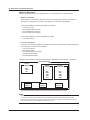
Manual Title
DL850E/DL850EV
ScopeCorder
Features Guide
DL850E/DL850EV
ScopeCorder
User’s Manual
DL850E/DL850EV
ScopeCorder
Getting Started Guide
DL850E/DL850EV
ScopeCorder
Communication Interface
User’s Manual
DL850E/DL850EV
ScopeCorder
Real Time Math/Power Math
User’s Manual
DL850E/DL850EV
ScopeCorder
Acquisition Software
User’s Manual
Notes
Manual No.
IM DL850E-01EN
IM DL850E-02EN
IM DL850E-03EN
IM DL850E-17EN
IM DL850E-51EN
IM DL850E-61EN
Description
The supplied CD contains the PDF file of this manual. This
manual explains all the DL850E/DL850EV features other
than the communication interface features.
The supplied CD contains the PDF file of this manual. The
manual explains how to operate the DL850E/DL850EV.
The manual explains the handling precautions and basic
operations of the DL850E/DL850EV and provides an
overview of its features.
This manual. The supplied CD contains the PDF file of
this manual. The manual explains the DL850E/DL850EV
communication interface features and instructions on how
to use them.
The supplied CD contains the PDF file of this manual.This
manual explains the features of the DL850E/DL850EV
Real Time Math/Power Math option and how to use them.
The supplied CD contains the PDF file of this manual. This
manual explains all the features of the acquisition software,
which performs continuous measurement on the DL850E/
DL850EV.
• The contents of this manual are subject to change without prior notice as a result of continuing
improvements to the instrument’s performance and functions. The figures given in this manual
may differ from those that actually appear on your screen.
• Every effort has been made in the preparation of this manual to ensure the accuracy of its
contents. However, should you have any questions or find any errors, please contact your
nearest YOKOGAWA dealer.
• Copying or reproducing all or any part of the contents of this manual without the permission of
YOKOGAWA is strictly prohibited.
• The TCP/IP software of this product and the documents concerning it have been developed/
created by YOKOGAWA based on the BSD Networking Software, Release 1 that has been
licensed from the Regents of the University of California.
1st Edition: December 2013 (YMI)
All Rights Reserved, Copyright © 2013, Yokogawa Meters & Instruments Corporation
IM DL850E-17EN
Trademarks
• Microsoft, Internet Explorer, MS-DOS, Windows, Windows NT, and Windows XP are either
registered trademarks or trademarks of Microsoft Corporation in the United States and/or other
countries.
• Adobe and Acrobat are trademarks of Adobe Systems Incorporated.
• GIGAZoom ENGINE is a registered trademark of Yokogawa Electric Corporation.
• In this manual, the ® and TM symbols do not accompany their respective registered trademark
or trademark names.
• Other company and product names are trademarks or registered trademarks of their respective
holders.
Revisions
• 1st Edition: December 2013
About the USB Interface and Ethernet Interface
• To use the USB communication features, your PC must have the following software:
• Communication library (TMCTL)
• YOKOGAWA USB TMC driver (dedicated USB driver)
• To use the Ethernet communication features, your PC must have the following software:
Communication library (TMCTL)
To download the library and driver listed above, go to the following website, and then browse to the
download page.
http://www.yokogawa.com/ymi/
ii
IM DL850E-17EN
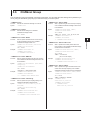
How to Use This Manual
Structure of the Manual
This manual contains six chapters and an appendix.
Chapter 1 Ethernet Interface
Describes the features and specifications of the Ethernet interface.
Chapter 2 USB Interface
Describes the features and specifications of the USB interface.
Chapter 3 GP-IB Interface (Optional)
Describes the features and specifications of the GP-IB interface.
Chapter 4 Programming Overview
Describes command syntax and other programming information.
Chapter 5 Commands
Describes every command individually.
Chapter 6 Status Reports
Describes the status byte, various registers, and queues.
Appendix
Provides reference material such as an ASCII character code table.
Index
IM DL850E-17EN
iii
How to Use This Manual
Conventions Used in This Manual
Notes and Cautions
The notes and cautions in this manual are categorized using the following symbols.
WARNING
Calls attention to actions or conditions that could cause serious or fatal injury to
the user, and precautions that can be taken to prevent such occurrences.
CAUTION
Calls attentions to actions or conditions that could cause light injury to the user
or damage to the instrument or user’s data, and precautions that can be taken to
prevent such occurrences.
Note Calls attention to information that is important for proper operation of the
instrument.
Character Notations
Hard Key Names and Soft Key Names in Bold Characters
Indicate panel keys that are used in the procedure and soft keys and menu items that appear on the screen.
SHIFT+Panel Key
When SHIFT+panel key appears in a procedural explanation, it means to press the shift key so that its
indicator lights, and then to press the indicated panel key. A setup menu for the item written in purple above
the key that you pressed appears on the screen.
Unit
k
K
Denotes 1000. Example:100 kS/s (sample rate)
Denotes 1024. Example:720 KB (file size)
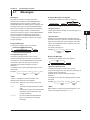
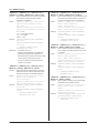
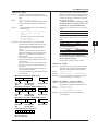
Metasyntax
The following table contains the symbols that are used in the syntax discussed mainly in chapters 4
and 5. These symbols are referred to as BNF (Backus-Naur Form) symbols. For details on how to
write data using these symbols, see pages 4-6 and 4-7.
Symbol
<>
{}
|
[]
iv
Description
A defined value
Select an option in { }
Exclusive OR
Can be omitted
Syntax Example
CHANnel<x> <x> = 1 to 4
COUPling {AC|DC|DC50|GND}
Example
CHANNEL2
COUPLING AC
TRIGger [:SIMPle]:SLOPe
TRIGger:SLOPe
IM DL850E-17EN
Contents
1
How to Use This Manual................................................................................................................... iii
Chapter 1 Ethernet Interface
1.1
1.2
1.3
1.4
Component Names and Functions.................................................................................... 1-1
Ethernet Interface Features and Specifications................................................................ 1-2
Connecting to the Ethernet Interface................................................................................. 1-4
Configuring the DL850E/DL850EV Ethernet Settings....................................................... 1-5
Chapter 2 USB Interface
2.1
2.2
2.3
2.4
Component Names and Functions.................................................................................... 2-1
USB Interface Features and Specifications....................................................................... 2-2
Connecting to the USB Interface....................................................................................... 2-3
Configuring the DL850E/DL850EV USB Settings............................................................. 2-4
2
3
4
5
Chapter 3 GP-IB Interface (Optional)
3.1
3.2
3.3
3.4
3.5
3.6
Component Names and Functions.................................................................................... 3-1
Connecting GP-IB Cables (Optional)................................................................................ 3-2
GP-IB Interface Features.................................................................................................. 3-4
GP-IB Interface Specifications.......................................................................................... 3-5
Configuring the DL850E/DL850EV GP-IB Settings........................................................... 3-6
Responses to Interface Messages.................................................................................... 3-7
Chapter 4 Programming Overview
4.1
4.2
4.3
4.4
4.5
Messages.......................................................................................................................... 4-1
Commands........................................................................................................................ 4-3
Response.......................................................................................................................... 4-5
Data................................................................................................................................... 4-6
Synchronization with the Controller................................................................................... 4-8
Chapter 5 Commands
5.1
5.2
5.3
5.4
5.5
5.6
5.7
5.8
5.9
5.10
5.11
5.12
5.13
5.14
5.15
5.16
5.17
5.18
5.19
IM DL850E-17EN
List of Commands............................................................................................................. 5-1
ACQuire Group................................................................................................................ 5-28
ASETup Group................................................................................................................ 5-30
CALibrate Group............................................................................................................. 5-31
CAPTure Group............................................................................................................... 5-32
CHANnel Group.............................................................................................................. 5-35
CLEar Group................................................................................................................... 5-66
COMMunicate Group...................................................................................................... 5-67
CURSor Group................................................................................................................ 5-69
DISPlay Group................................................................................................................ 5-81
EVENt Group................................................................................................................... 5-84
FFT Group....................................................................................................................... 5-85
FILE Group...................................................................................................................... 5-89
GONogo Group............................................................................................................... 5-93
HCOPy Group................................................................................................................. 5-98
HISTory Group................................................................................................................. 5-99
IMAGe Group................................................................................................................ 5-102
INITialize Group............................................................................................................. 5-103
LSTart Group................................................................................................................. 5-104
6
App
Index
Contents
5.20
5.21
5.22
5.23
5.24
5.25
5.26
5.27
5.28
5.29
5.30
5.31
5.32
5.33
5.34
5.35
5.36
5.37
5.38
MATH Group................................................................................................................. 5-105
MEASure Group.............................................................................................................5-110
MONitor Group.............................................................................................................. 5-121
MTRigger Group............................................................................................................ 5-123
RECall Group................................................................................................................ 5-124
SEARch Group.............................................................................................................. 5-125
SNAP Group.................................................................................................................. 5-128
SSTart Group................................................................................................................. 5-129
STARt Group................................................................................................................. 5-130
STATus Group............................................................................................................... 5-131
STOP Group.................................................................................................................. 5-132
STORe Group............................................................................................................... 5-133
SYSTem Group............................................................................................................. 5-134
TIMebase Group........................................................................................................... 5-139
TRIGger Group.............................................................................................................. 5-140
WAVeform Group........................................................................................................... 5-151
XY Group....................................................................................................................... 5-157
ZOOM Group................................................................................................................. 5-159
Common Command Group........................................................................................... 5-161
Chapter 6 Status Reports
6.1
6.2
6.3
6.4
6.5
Appendix
About Status Reports........................................................................................................ 6-1
Status Byte........................................................................................................................ 6-3
Standard Event Register................................................................................................... 6-4
Extended Event Register................................................................................................... 6-5
Output and Error Queues.................................................................................................. 6-6
Appendix 1
Appendix 2
Appendix 3
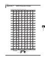
ASCII Character Codes....................................................................................... App-1
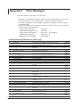
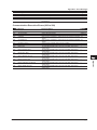
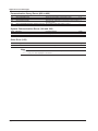
Error Messages................................................................................................... App-2
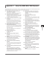
About the IEEE 488.2-1992 Standard................................................................. App-5
Index
vi
IM DL850E-17EN
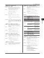
Chapter 1
1.1
Ethernet Interface
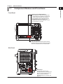
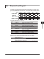
Component Names and Functions
Ethernet Interface
Front Panel
1
2
SHIFT key and CLEAR TRACE key
Press these keys to switch from remote mode,
in which settings and operations are performed
through remote commands, to local mode, in
which operations can be performed using the
DL850E/DL850EV keys. These keys are
disabled when local lockout (see page 1-2) has
been activated by a controller.
3
4
RESET
SET
ESC
START / STOP
SETUP
DISPLAY
CAL
X-Y
VERTICAL
CH 1
CH
CH
5
9
CH 13
CH
2
CH
6
4
CH
3
CH
7
5
2
CH 11
CH14
SCALE
9
TRIG’D
MODE
4
CH
8
CH16
EXP
k
m
CH12
CH15
ENTER
POSITION
PUSH
O DIV
NUM LOCK
TIME / DIV
CH
6
3
ALL CH
HORIZONTAL
5
ACQUIRE
DUAL CAPTURE
8
CH 10
0
FILE
MENU
7
1
SAVE
6
TRIGGER
POSITION / DELAY
ACTION
MANUAL TRIG
MATH
HISTORY
MEASURE
HELP
PRINT
PRINT MENU
MENU
DUAL CAPTURE
SNAP SHOT
CLEAR TRACE
CLR
HDD RECORDING
CURSOR
GO / NO-GO
FFT
POSITION
ZOOM
MAG
KEY PROTECT
SIMPLE / ENHANCED
UTILITY
SEARCH
SHIFT
PUSH
Z 1
Z 2
App
PUSH
COMP
UTILITY key (page 1-5)
Press this key to set the communication interface
and timeout value for remote control and to set the
user name and password for user authentication.
Index
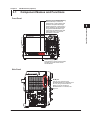
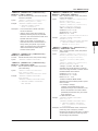
Side Panel
GP-IB
(IEEE488)
IRIG
100-120/220-240 V AC
200 VA MAX 50/60 Hz
EXT HDD
EXT I/O
SD
POWER
ON
EXT CLKIN
OFF
VIDEO OUT
(XGA)
TRIGGER
IN
OUT
Made in Japan
IM DL850E-17EN
ETHERNET
1000BASE-T
Ethernet port
This port is for connecting the
DL850E/DL850EV to a controller (such
as a PC) using an Ethernet cable. For
details on how to connect the
DL850E/DL850EV to a controller, see
page 1-4.
1-1
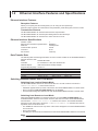
1.2
Ethernet Interface Features and Specifications
Ethernet Interface Features
Reception Features
Allows you to specify the same settings that you can using the front panel keys.
Receives output requests for measured and computed data, panel setting data, and error codes.
Transmission Features
The DL850E/DL850EV can transmit measured and computed data.
The DL850E/DL850EV can transmit panel setting data and the status byte.
The DL850E/DL850EV can transmit error codes when errors occur.
Ethernet Interface Specifications
Number of ports:
Electrical and mechanical specifications:
Data rate:
Communication protocol:
Connector:
Port number:
1
IEEE802.3
100 Mbps max.
TCP/IP
RJ-45
10001/tcp
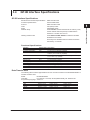
Data Transfer Rate
The following table contains approximations of how much time it takes for the DL850E/DL850EV to
transmit waveform data.
Model: DL850E/DL850EV
Controller: PC: Pentium4 3.2 GHz, OS: Windows XP
Network adapter: Intel PRO/1000 GT Desktop Adapter
Programming language: Visual C++
Number of Data Points
1000
10000
100000
1000000
Byte Data
Approx. 1 ms
Approx. 1 ms
Approx. 10 ms
Approx. 100 ms
Word Data
Approx. 1 ms
Approx. 2 ms
Approx. 11 ms
Approx. 125 ms
ASCII Data
Approx. 30 ms
Approx. 300 ms
Approx. 3 s
Approx. 30 s
Switching between Remote and Local Modes
Switching from Local to Remote Mode
The DL850E/DL850EV switches to remote mode when it is in local mode and it receives a :
COMMunicate:REMote ON command from the PC.
• “REMOTE” appears at the top center of the screen once the DL850E/DL850EV is in remote mode.
• All keys except the SHIFT+CLEAR TRACE keys are disabled.
• The local mode settings are retained even when the DL850E/DL850EV switches to remote mode.
Switching from Remote to Local Mode
When the DL850E/DL850EV is in Remote mode and you press SHIFT+CLEAR TRACE, the
DL850E/DL850EV switches to local mode. However, this does not work if the DL850E/DL850EV
has received a :COMMunicate:LOCKout ON command from the PC. The DL850E/DL850EV
switches to local mode when it receives a :COMMunicate:REMote OFF command from the PC,
regardless of the local lockout state.
• The “REMOTE” indicator at the top center of the screen disappears once the DL850E/DL850EV
is in local mode.
• All keys are enabled.
• The settings in remote mode are retained even when the DL850E/DL850EV switches to local mode.
Note
You cannot use the Ethernet interface at the same time as other interfaces (GP-IB and USB interfaces).
1-2
IM DL850E-17EN
1.2 Ethernet Interface Features and Specifications
User Verification Function
1
Ethernet Interface
To connect the DL850E/DL850EV to a network as an FTP server, you have to enter a
user name and password in the Ethernet-communication-interface settings. To set the
user name and password, access the UTILITY menu, the Network menu, and then the
FTP Server screen. For details, see section 17.3, “Accessing the DL850E/DL850EV from
a PC (FTP Server)” in the DL850E/DL850EV User’s Manual, IM DL850E-02EN.
2
3
4
5
6
App
Index
IM DL850E-17EN
1-3
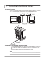
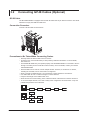
1.3
Connecting to the Ethernet Interface
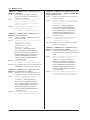
Connection Procedure
Connect a UTP (Unshielded Twisted-Pair) or STP (Shielded Twisted-Pair) cable that is connected to
a hub or other network device to the Ethernet port on the DL850E/DL850EV side panel.
Hub or router that supports 1000BASE-T/100BASE-TX
Controller
(PC or work station)
DL850E/DL850EV
UTP or STP cable
(straight cable)
Network card
Ethernet port
RJ-45 modular jack
Precautions to Be Taken When Connecting Probes
• To connect the DL850E/DL850EV to a PC, be sure to use straight cables and to connect through
a hub or router. Proper operation is not guaranteed for a one-to-one connection using a cross
cable.
• Use a network cable that conforms to the transfer speed of your network.
Note
For details on how to connect the DL850E/DL850EV to a network, see section 17.1, “Connecting the
DL850E/DL850EV to a Network” in the DL850E/DL850EV User’s Manual, IM DL850E-02EN.
1-4
IM DL850E-17EN
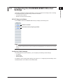
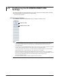
1.4
Configuring the DL850E/DL850EV Ethernet
Settings
1
UTILITY Remote Ctrl Menu
Ethernet Interface
This section explains the settings listed below. You must configure these settings when controlling
the DL850E/DL850EV remotely through an Ethernet interface.
• Communication interface
• Network connection timeout setting
2
3
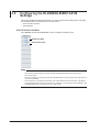
Press UTILITY and then the Remote Ctrl soft key to display the following menu.
4
Set Device to Network.
5
Set the timeout value (using the jog shuttle).
6
App
Index
Note
Only use the selected communication interface. If you send commands simultaneously from another
communication interface that has not been selected, the DL850E/DL850EV will not execute the commands
properly.
Configuring TCP/IP Settings
To use the Ethernet interface features, you must specify the following TCP/IP settings.
• IP address
• Subnet mask
• Default gateway
For details on how to specify these settings, see section 17.2, “Configuring TCP/IP Settings” in the
DL850E/DL850EV User’s Manual, IM DL850E-02EN.
IM DL850E-17EN
1-5
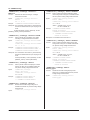
Chapter 2
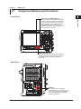
2.1
USB Interface
Component Names and Functions
Front Panel
1
2
USB Interface
SHIFT key and CLEAR TRACE key
Press these keys to switch from remote mode,
in which settings and operations are performed
through remote commands, to local mode, in
which operations can be performed using the
DL850E/DL850EV keys. These keys are
disabled when local lockout (see page 2-2) has
been activated by a controller.
3
4
RESET
SET
ESC
START / STOP
SETUP
DISPLAY
CAL
X-Y
VERTICAL
CH 1
CH
CH
5
9
CH 13
CH
2
CH
6
4
CH
3
CH
7
5
2
CH 11
CH14
SCALE
9
TRIG’D
MODE
4
CH
8
CH16
EXP
k
m
CH12
CH15
ENTER
POSITION
PUSH
O DIV
NUM LOCK
TIME / DIV
CH
6
3
ALL CH
HORIZONTAL
5
ACQUIRE
DUAL CAPTURE
8
CH 10
0
FILE
MENU
7
1
SAVE
6
TRIGGER
POSITION / DELAY
ACTION
MANUAL TRIG
MATH
HISTORY
MEASURE
HELP
PRINT
PRINT MENU
MENU
DUAL CAPTURE
SNAP SHOT
CLEAR TRACE
CLR
HDD RECORDING
CURSOR
GO / NO-GO
FFT
POSITION
ZOOM
MAG
KEY PROTECT
SIMPLE / ENHANCED
UTILITY
SEARCH
SHIFT
PUSH
Z 1
Z 2
App
PUSH
COMP
UTILITY key (page 2-4)
Press this key to set the communication interface for
remote control and to enable remote control through
the USB ports (when you want to use remote
commands).
Index
Side Panel
GP-IB
(IEEE488)
IRIG
100-120/220-240 V AC
200 VA MAX 50/60 Hz
EXT HDD
EXT I/O
SD
POWER
ON
EXT CLKIN
OFF
VIDEO OUT
(XGA)
TRIGGER
IN
OUT
Made in Japan
IM DL850E-17EN
ETHERNET
1000BASE-T
USB ports
These ports are for connecting the
DL850E/DL850EV to a controller (such as
a PC) using a USB cable. For details on
how to connect the DL850E/DL850EV to a
controller, see page 2-3.
2-1
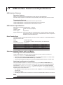
2.2
USB Interface Features and Specifications
USB Interface Features
Reception Features
Allows you to specify the same settings that you can using the front panel keys.
Receives output requests for measured and computed data, panel setting data, and error codes.
Transmission Features
The DL850E/DL850EV can transmit measured and computed data.
The DL850E/DL850EV can transmit panel setting data and the status byte.
The DL850E/DL850EV can transmit error codes when errors occur.
USB Interface Specifications
Electrical and mechanical specifications: USB 2.0
Connector: Type B connector (receptacle)
Number of ports: 2
Power supply: Self powered
System requirements:A PC with a USB port, running Windows 7 (32 bit), Windows Vista (32 bit),
or Windows XP (32 bit, SP2 or later). A separate device driver is required to
enable the connection with the PC.
Data Transfer Rate
The following table contains approximations of how much time it takes for the DL850E/DL850EV to
transmit waveform data.
Model: DL850E/DL850EV
Controller: PC: Pentium 4 3.2 GHz, USB 2.0 (ICH6), OS: Windows XP
Programming language: Visual C++
Number of Data Points
1000
10000
100000
1000000
Byte Data
Approx. 1 ms
Approx. 1 ms
Approx. 16 ms
Approx. 111 ms
Word Data
Approx. 1 ms
Approx. 2 ms
Approx. 15 ms
Approx. 170 ms
ASCII Data
Approx. 30 ms
Approx. 300 ms
Approx. 3 s
Approx. 30 s
Switching between Remote and Local Modes
Switching from Local to Remote Mode
The DL850E/DL850EV switches to remote mode when it is in local mode and it receives a :
COMMunicate:REMote ON command from the PC.
• “REMOTE” appears at the top center of the screen once the DL850E/DL850EV is in remote mode.
• All keys except the SHIFT+CLEAR TRACE keys are disabled.
• The local mode settings are retained even when the DL850E/DL850EV switches to remote mode.
Switching from Remote to Local Mode
When the DL850E/DL850EV is in Remote mode and you press SHIFT+CLEAR TRACE, the
DL850E/DL850EV switches to local mode. However, this does not work if the DL850E/DL850EV
has received a :COMMunicate:LOCKout ON command from the PC. The DL850E/DL850EV
switches to local mode when it receives a :COMMunicate:REMote OFF command from the PC,
regardless of the local lockout state.
• The “REMOTE” indicator at the top center of the screen disappears once the DL850E/DL850EV is
in local mode.
• All keys are enabled.
• The settings in remote mode are retained even when the DL850E/DL850EV switches to local mode.
Note
You cannot use the USB interface at the same time as other interfaces (GP-IB and Ethernet interfaces).
2-2
IM DL850E-17EN
2.3
Connecting to the USB Interface
1
Precautions to Be Taken When Connecting Probes
2
USB Interface
• Be sure to insert the USB cable connectors firmly into the USB ports.
• If you are connecting multiple devices by using a USB hub, connect the DL850E/DL850EV to the
USB hub port that is closest to the port that the controller is connected to.
• Do not connect a USB cable (type B) to the GO/NO-GO output terminal. Doing so may damage
the DL850E/DL850EV.
• Do not connect or remove USB cables from the time when the DL850E/DL850EV is turned on
until operation becomes available (approximately 20 to 30 seconds). Doing so may damage the
DL850E/DL850EV.
3
4
5
6
App
Index
IM DL850E-17EN
2-3
2.4
Configuring the DL850E/DL850EV USB
Settings
This section explains the settings listed below. You must configure these settings when controlling
the DL850E/DL850EV remotely through a USB interface.
• Communication interface
UTILITY Remote Ctrl Menu
Press UTILITY and then the Remote Ctrl soft key to display the following menu.
Set Device to USB.
Set USB Function to TMC.
Note
• Only use the selected communication interface. If you send commands simultaneously from another
communication interface that has not been selected, the DL850E/DL850EV will not execute the
commands properly.
• To remotely control the DL850E/DL850EV through a USB port using communication commands, set USB
Function, shown in the figure above, to TMC, and then carry out the following steps.
• To activate the USB Function settings, you need to restart the DL850E/DL850EV. Turn off the DL850E/
DL850EV power switch, wait ten seconds or more, and then turn on the switch.
• Install the YOKOGAWA USB TMC (Test and Measurement Class) driver on your PC. For information
about how to obtain the YOKOGAWA USB TMC driver, contact your nearest YOKOGAWA dealer. You can
also access the YOKOGAWA USB driver download webpage and download the driver.
http://www.yokogawa.com/ymi/
• Do not use USB TMC drivers (or software) supplied by other companies.
2-4
IM DL850E-17EN
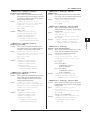
Chapter 3
3.1
GP-IB Interface (Optional)
Component Names and Functions
Front Panel
1
2
SHIFT key and CLEAR TRACE key
Press these keys to switch from
remote mode, in which settings and
operations are performed through
remote commands, to local mode, in
which operations can be performed
using the DL850E/DL850EV keys.
These keys are disabled when local
lockout (see page 3-7) has been
activated by a controller.
3
GP-IB Interface (Optional)
4
RESET
SET
ESC
5
START / STOP
SETUP
SAVE
DISPLAY
CH
5
CH
9
CH 13
7
CH
2
CH
6
4
1
ACQUIRE
DUAL CAPTURE
8
2
3
CH
7
CH 11
CH14
SCALE
CH
5
CH 10
0
FILE
MENU
X-Y
CAL
VERTICAL
CH 1
9
TIME / DIV
MODE
CH
8
CH16
EXP
k
m
CH12
CH15
TRIG’D
4
6
3
ALL CH
ENTER
6
POSITION
PUSH
O DIV
NUM LOCK
HORIZONTAL
CH
TRIGGER
POSITION / DELAY
ACTION
MANUAL TRIG
MATH
HISTORY
HELP
PRINT
PRINT MENU
MENU
DUAL CAPTURE
SNAP SHOT
CLEAR TRACE
CLR
HDD RECORDING
CURSOR
GO / NO-GO
FFT
POSITION
ZOOM
MAG
KEY PROTECT
SIMPLE / ENHANCED
MEASURE
App
UTILITY
SEARCH
SHIFT
PUSH
Z 1
Z 2
PUSH
COMP
Index
UTILITY key (page 3-5)
Press this key to set the communication
interface for remote control and the
GP-IB address.
Side Panel
GP-IB
(IEEE488)
GP-IB port
This port is for connecting the
DL850E/DL850EV to a controller (such
as a PC) using a GP-IB cable. For
details on how to connect the
DL850/DL850V to a controller, see
page 3-2.
IRIG
100-120/220-240 V AC
200 VA MAX 50/60 Hz
EXT HDD
EXT I/O
SD
POWER
ON
EXT CLKIN
OFF
VIDEO OUT
(XGA)
TRIGGER
IN
OUT
Made in Japan
IM DL850E-17EN
ETHERNET
1000BASE-T
3-1
3.2
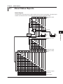
Connecting GP-IB Cables (Optional)
GP-IB Cable
The DL850E/DL850EV is equipped with an IEEE St’d 488-1978 24-pin GP-IB connector. Use GP-IB
cables that comply with IEEE St’d 488-1978.
Connection Procedure
Connect a GP-IB cable as shown below.
Precautions to Be Taken When Connecting Probes
• Securely fasten the GP-IB cable connector screws.
• On the PC end, use a GP-IB board (or card) made by National Instruments. For more details,
see section 3.4.
• The DL850E/DL850EV may not operate properly if the DL850E/DL850EV is connected to the PC
through converters (such as a GP-IB to USB converter). For more details, contact your nearest
YOKOGAWA dealer.
• Several cables can be used to connect multiple devices. However, no more than 15 devices,
including the controller, can be connected on a single bus.
• When connecting multiple devices, you must assign a unique address to each device.
• Use cables that are 2 m or shorter in length to connect devices.
• Keep the total length of the cables under 20 m.
• When devices are communicating, have at least two-thirds of the devices on the bus turned on.
• To connect multiple devices, use a star or daisy-chain configuration as shown below. Loop and
parallel configurations are not allowed.
3-2
IM DL850E-17EN
3.2 Connecting GP-IB Cables (Optional)
1
CAUTION
Be sure to turn off the PC and the DL850E/DL850EV when connecting or removing
communication cables. Otherwise, erroneous operation may result, or the internal circuitry
may break.
2
3
GP-IB Interface (Optional)
4
5
6
App
Index
IM DL850E-17EN
3-3
3.3
GP-IB Interface Features
GP-IB Interface Features
Listener Capabilities
• Allows you to specify the same DL850E/DL850EV settings that you can using the front panel
keys. You cannot turn the power on and off or change communication settings.
• Receives output requests for measured and computed data, panel setting data, and error codes.
• Receives status report commands and other commands.
Talker Capabilities
The DL850E/DL850EV can transmit measured and computed data.
The DL850E/DL850EV can transmit panel setting data and the status byte.
The DL850E/DL850EV can transmit error codes when errors occur.
Note
Talk-only, listen-only, and controller capabilities are not available on the DL850E/DL850EV.
Switching between Remote and Local Modes
Switching from Local to Remote Mode
The DL850E/DL850EV switches to remote mode when it is in local mode and it receives a REN
(Remote Enable) message from the PC.
• “REMOTE” appears at the top center of the screen once the DL850E/DL850EV is in remote
mode.
• All keys except the SHIFT+CLEAR TRACE keys are disabled.
• The local mode settings are retained even when the DL850E/DL850EV switches to remote
mode.
Switching from Remote to Local Mode
When the DL850E/DL850EV is in Remote mode and you press SHIFT+CLEAR TRACE, the
DL850E/DL850EV switches to local mode. These keys are disabled when local lockout (see page
3-7) has been activated by a controller.
• The “REMOTE” indicator at the top center of the screen disappears once the DL850E/DL850EV
is in local mode.
• All keys are enabled.
• The settings in remote mode are retained even when the DL850E/DL850EV switches to local
mode.
Note
You cannot use the GP-IB interface simultaneously with other interfaces (USB and Ethernet interfaces).
3-4
IM DL850E-17EN
3.4
GP-IB Interface Specifications
1
GP-IB Interface Specifications
Functional Specifications
Function
Source handshaking
Acceptor handshaking
Talker
Subset Name
SH1
AH1
T6
Listener
L4
Service request
Remote local
Parallel polling
Device clear
Device trigger
Controller
Electric characteristics
SR1
RL1
PP0
DC1
DT0
C0
E1
Description
Full source handshaking capability
Full acceptor handshaking capability
Basic talker capability, serial polling, untalk on MLA (My Listen
Address), and no talk-only capability
Basic listener capability, unlisten on MTA (My Talk Address),
and no listen-only capability
Full service request capability
Full remote/local capability
No parallel poll capability
Full device clear capability
No device trigger capability
No controller capability
Open collector
Data Transfer Rate
The following table contains approximations of how much time it takes for the DL850E/DL850EV to
transmit waveform data.
Model: DL850E/DL850EV
Controller: PC: Pentium 4 3.2 GHz, GP-IB (GPIB-USB-B), OS: Windows XP
Programming language: Visual C++
Number of Data Points
1000
10000
100000
1000000
IM DL850E-17EN
Byte Data
Approx. 24 ms
Approx. 31 ms
Approx. 170 ms
Approx. 1600 ms
Word Data
Approx. 20 ms
Approx. 44 ms
Approx. 310 ms
Approx. 3100 ms
ASCII Data
Approx. 54 ms
Approx. 510 ms
Approx. 5 s
Approx. 50 s
3-5
3
GP-IB Interface (Optional)
Electrical and mechanical specifications: IEEE St’d 488-1978
Functional specifications: See the table below.
Protocol: IEEE St’d 488.2-1992
Code: ISO (ASCII) codes
Mode: Addressable mode
Address setup:Press UTILITY and then the Remote Ctrl soft key. Then,
set the network interface (Device) to GPIB and the
address to a number from 0 to 30.
Clearing remote mode:Press SHIFT+CLEAR TRACE to switch the DL850E/
DL850EV to local mode.
These keys are disabled when local lockout has been
activated by a controller.
2
4
5
6
App
Index
3.5
Configuring the DL850E/DL850EV GP-IB
Settings
This section explains the settings listed below. You must configure these settings when controlling
the DL850E/DL850EV remotely through a GP-IB interface.
• Communication interface
• GP-IB address
UTILITY Remote Ctrl Menu
Press UTILITY and then the Remote Ctrl soft key to display the following menu.
Set Device to GPIB.
Set the address (0-30).
Note
• Only use the selected communication interface. If you send commands simultaneously from another
communication interface that has not been selected, the DL850E/DL850EV will not execute the
commands properly.
• When the controller is communicating with the DL850E/DL850EV or with other devices through GP-IB, do
not change the address.
• Each device that is connected by GP-IB has its own unique address in the GP-IB system. This address
is used to distinguish one device from other devices. Therefore, you must assign a unique address to the
DL850E/DL850EV when connecting it to a PC or other device.
3-6
IM DL850E-17EN
3.6
Responses to Interface Messages
1
2
Responses to Interface Messages
Responses to Uni-Line Messages
• IFC (Interface Clear)
3
Clears the talker and listener functions. Stops data transmission if it is in progress.
GP-IB Interface (Optional)
• REN (Remote Enable)
Switches between remote and local modes.
4
IDY (Identify) is not supported.
Responses to Multi-Line Messages (Address commands)
5
• GTL (Go To Local)
Switches to local mode.
• SDC (Selected Device Clear)
6
• Clears the program message (command) being received and the output queue (see page
6-6).
• Discards *OPC and *OPC? commands that are being executed.
• Immediately aborts *WAI and COMMunicate:WAIT.
App
PPC (Parallel Poll Configure), GET (Group Execute Trigger), and TCT (Take Control) are not
supported.
Index
Responses to Multi-Line Messages (Universal commands)
• LLO (Local Lockout)
Disables the CLEAR TRACE key on the front panel to prohibit switching to the local mode.
• DCL (Device Clear)
Performs the same operation as SDC.
• SPE (Serial Poll Enable)
Sets the talker function on all devices on the bus to serial polling mode. The controller will poll
each device in order.
• SPD (Serial Poll Disable)
Clears the talker function’s serial poll mode on all devices on the bus.
PPU (Parallel Poll Unconfigure) is not supported.
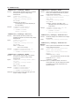
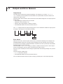
What Are Interface Messages?
Interface messages are commands that a controller transmits. They are also referred to as interface
commands or bus commands. They are classified as follows:
Uni-line Messages
Uni-line messages are sent over a single control line. The following three terminators are available.
• IFC (Interface Clear)
• REN (Remote Enable)
• IDY (Identify)
IM DL850E-17EN
3-7
3.6 Responses to Interface Messages
Multi-line Messages
Multi-line messages are sent over eight data lines. The messages are grouped as follows:
• Address Commands
Some address commands are valid when a device is designated as a listener, and some are
valid when it is designated as a talker. The following five commands are available.
Commands available to a device designated as a listener
• GTL (Go To Local)
• SDC (Selected Device Clear)
• PPC (Parallel Poll Configure)
• GET (Group Execute Trigger)
Commands available to a device designated as a talker
• TCT (Take Control)
• Universal Commands
Universal commands are available to all devices regardless of their listener or talker designation.
The following five commands are available.
• LLO (Local Lockout)
• DCL (Device Clear)
• PPU (Parallel Poll Unconfigure)
• SPE (Serial Poll Enable)
• SPD (Serial Poll Disable)
There are other interface messages: listener-address, talk-address, and secondary commands.
Uni-line
Messages
Interface Messages
Multi-line Messages
Address
commands
*IFC
*REN
IDY
*GTL
*SDC
PPC
GET
TCT
Listener
address
Talker
address
Universal
commands
*LLO
*DCL
PPU
*SPE
*SPD
Secondary
command
The DL850E/DL850EV supports interface messages marked with an asterisk.
Note
Difference between SDC and DCL
In multi-line messages, SDC messages are those that require talker or listener designation and DCL
messages are those that do not require the designation. Therefore, the SDC command affects a specific
device while the DCL command affects all devices on the bus.
3-8
IM DL850E-17EN
Chapter 4
4.1
Programming Overview
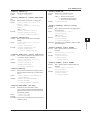
Messages
1
Messages
Program Message
The program message syntax is as follows:
;
<Program message unit>
<PMT>
Program Message Unit Syntax
,
<Program header>
Space
Unit
Unit
<PMT>
<PMT> is a program message terminator. The
following three terminators are available.
NL (new line): Same as LF (line feed). ASCII code
“0AH”
^END:
The END message as defined by IEEE
488.1
(The data byte that is sent with the END
message is the last data byte of the
program message.)
NL^END:
NL with an END message attached.
(NL is not included in the program
message.)
IM DL850E-17EN
<Program data>
3
<Program Header>
The program header indicates the command type. For
details, see page 4-3.
<Program Data>
Attach program data if there are conditions that are
required to execute a command. Separate the program
data from the header with a space (ASCII code 20H).
If there are multiple data values, separate each data
value with a comma.
For details, see page 4-6.
Example :ACQuire:MODE NORMal<PMT>
Header
<Program Message Unit>
A program message consists of one or more
program message units. Each unit corresponds to
one command. The DL850E/DL850EV executes the
commands in the order that they are received.
Separate each program message unit with a
semicolon.
For details on the program message syntax, see the
next section.
Example :ACQuire:MODE NORMal;COUNt 1<PMT>
2
The program message unit syntax is as follows:
Data
4
Programming Overview
Messages are used to exchange information
between the controller and the DL850E/DL850EV.
Messages that are sent from the controller to the
DL850E/DL850EV are called program messages, and
messages that are sent from the DL850E/DL850EV
back to the controller are called response messages.
If a program message contains a command that
requests a response (a query), the DL850E/DL850EV
returns a response message upon receiving the
program message. The DL850E/DL850EV returns
a single response message in response to a single
program message.
5
6
App
Response Message
The response message syntax is as follows:
Index
;
<Response message unit>
<RMT>
<Response Message Unit>
A response message consists of one or more
response message units; each response message unit
corresponds to one response.
Separate each response message unit with a
semicolon.
For details on the response message syntax, see the
next page.
Example :ACQUIRE:MODE NORMAL;COUNT 1<RMT>
Unit
Unit
<RMT>
RMT stands for “response message terminator.” The
response message terminator is NL^END.
4-1
4.1 Messages
Response Message Unit Syntax
The response message unit syntax is as follows:
,
<Response header>
Space
<Response data>
<Response Header>
A response header sometimes precedes the response
data. A space separates the data from the header. For
details, see page 4-5.
<Response Data>
Response data contains the content of the response.
If there are multiple data values, each data value is
separated by a comma. For details, see page 4-5.
Example
1.25E-02<RMT> :ACQUIRE:MODE NORMAL<RMT>
Data
Header
Data
If there are multiple queries in a program message,
responses are returned in the same order that the
queries were received in. In most cases, a single query
returns a single response message unit, but there
are a few queries that return multiple units. The first
response message unit always corresponds to the first
query, but the nth response unit may not necessarily
correspond to the nth query. If you want to make sure
that every response is retrieved, divide the program
messages into individual messages.
• If the controller sends a program message
containing multiple message units, but the message
contains incomplete units, the DL850E/DL850EV
will try to execute the ones that are believed to
be complete. However, these attempts may not
always be successful. In addition, if such a message
contains queries, the DL850E/DL850EV may not
necessary return responses.
Deadlock
The DL850E/DL850EV can store at least 1024 bytes
of messages in its transmit and receive buffers (the
number of available bytes varies depending on the
operating conditions). If both the transmit and receive
buffers become full at the same time, the DL850E/
DL850EV will no longer be able to operate. This
condition is called a deadlock. If this happens, you can
resume operation after you have discarded response
messages.
Deadlock will not occur if the program message
(including the <PMT>) is kept below 1024 bytes.
Program messages that do not contain queries never
cause deadlocks.
Precautions to Be Taken when Exchanging
Messages
• If the controller sends a program message that does
not contain a query, the controller can send the next
program message at any time.
• If the controller sends a program message that
contains a query, the controller must finish receiving
the response message before it can send the next
program message. If the controller sends the next
program message before receiving the response
message in its entirety, an error will occur. A
response message that is not received in its entirety
will be discarded.
• If the controller tries to receive a response message
when there is none, an error will occur. If the
controller tries to receive a response message
before the transmission of the program message is
complete, an error will occur.
4-2
IM DL850E-17EN
4.2
Commands
Commands
There are three types of commands (program headers)
that a controller may send to the DL850E/DL850EV.
The commands differ in their program header formats.
Common Command Header
*
?
<Mnemonic>
Common command example *CLS
Compound Header
Other commands that are specific to the DL850E/
DL850EV are classified and arranged in a hierarchy
according to their functions. The compound header
syntax is shown below. Be sure to use a colon to
specify a lower hierarchical level.
:
:
?
<Mnemonic>
Compound header example :ACQuire:MODE
Simple Header
These commands are functionally independent and are
not contained within a hierarchy. The format of a simple
header is shown below.
:
<Mnemonic>
?
Simple header example :STARt
Note
A <mnemonic> is an alphanumeric character string.
2
When Concatenating Commands
• Command Groups
A command group is a group of commands that
have common compound headers arranged in a
hierarchy. A command group may contain subgroups.
Example
3
Group of commands related to acquisition
:ACQuire:AVERage:COUNt
:ACQuire:MODE
:ACQuire:AVERage:EWEight
:ACQuire:CLOCK
:ACQuire:RLENgth
:ACQuire:COUNt
• When Concatenating Commands of the Same
Group
The DL850E/DL850EV stores the hierarchical level
of the command that is currently being executed and
processes the next command on the assumption
that it belongs to the same level. Therefore,
the common header section can be omitted for
commands that belong to the same group.
Example :ACQuire:MODE NORMal;
COUNt 1<PMT>
• When Concatenating Commands of Different
Groups
If the subsequent command does not belong to the
same group, place a colon in front of the header
(cannot be omitted).
Example :ACQuire:MODE NORMal;:DISPlay:
FORMat SINGle<PMT>
• When Concatenating Simple Headers
If a simple header follows another command, place
a colon in front of the simple header (cannot be
omitted).
Example :ACQuire:MODE NORMal;:
STARt<PMT>
• When Concatenating Common Commands
Common commands that are defined in IEEE
488.2-1992 are independent of hierarchy. There is
no need to use a colon.
Example :ACQuire:MODE NORMal;*CLS;
COUNt 1<PMT>
• When Separating Commands with <PMT>
If you separate two commands with a terminator,
two program messages will be sent. Therefore,
the common header must be specified for each
command even if commands belonging to the same
command group are being concatenated.
Example :ACQuire:MODE NORMal<PMT>:
ACQuire:COUNt 1<PMT>
IM DL850E-17EN
4-3
4
Programming Overview
Commands that are defined in IEEE 488.2-1987 are
called common commands. The header format of a
common command is shown below. Be sure to include
an asterisk (*) at the beginning of a common command.
1
5
6
App
Index
4.2 Commands
Upper-Level Query
An upper-level query is a query that is made by
appending a question mark to the highest level
command of a group. The controller can receive all
of the settings in a group collectively by executing
an upper-level query. Some upper-level queries of a
group, which may be comprised of more than three
hierarchical levels, can cause the DL850E/DL850EV to
transmit all the lower level settings.
CHANnel1?<PMT> -> :CHANNEL1:
Example:
DISPLAY ON;LABEL "CH1 ";
COUPLING DC;POSITION 0.00;
PROBE 10;VDIV 50.0E+00;
BWIDTH FULL;OFFSET 0.0E+00;
LSCALE:MODE 0
The response to an upper-level query can be sent
back to the DL850E/DL850EV as a program message.
This enables the settings that were present when the
upper-level query was made to be reproduced later
on. However, some upper-level queries do not return
setup data that is not currently in use. Exercise caution
because not all of a group’s information is necessarily
returned in a response.
Header Interpretation Rules
The DL850E/DL850EV interprets the header that it
receives according to the rules below.
• Mnemonics are not case sensitive.
ExampleCURSor can be written as
cursor or Cursor.
• The lower-case characters can be omitted.
ExampleCURSor can be written as
CURSO or CURS.
• The question mark at the end of a header indicates
that it is a query. You cannot omit the question mark.
ExampleThe shortest abbreviation for
CURSor? is CURS?.
• If the <x> (value) at the end of a mnemonic is
omitted, it is interpreted as a 1.
ExampleIf you write CHAN for CHANnel<x>,
CHANnel1 is specified.
• Parts of commands and parameters enclosed in
square brackets ([ ]) can be omitted.
ExampleTRIGger[:SIMPle]:LEVel can
be written as TRIG:LEV.
However, the last section enclosed in brackets
cannot be omitted in an upper-level query.
ExampleTRIGger? and
TRIGger:SIMPle? are different
queries.
4-4
IM DL850E-17EN
4.3
Response
1
Response
2
When the controller sends a query with a question
mark, the DL850E/DL850EV returns a response
message to the query. The DL850E/DL850EV returns
response messages in one of the following two forms.
3
• Response Consisting of a Header and Data
Responses that can be used as program messages
without any changes are returned with command
headers attached.
Example:ACQUire:MODE?<PMT> ->
:ACQUire:MODE NORMAL<RMT>
4
Programming Overview
5
• Response Only Consisting of Data
Responses that cannot be used as program
messages unless changes are made (query-only
commands) are returned without headers. However,
there are query-only commands whose responses
the DL850E/DL850EV will attach headers to.
Example:MEASure:CHANnel1:PTOPeak:
VALue?<PMT> -> 10.0E+00<RMT>
6
App
If You Want the DL850E/DL850EV to Return
Responses without Headers
Index
You can configure the DL850E/DL850EV so that
even responses that have both headers and data are
returned without headers. Use the
COMMunicate:HEADer command for this purpose.
Abbreviated Form
The DL850E/DL850EV normally returns response
headers with the lower-case section removed. You can
configure the DL850E/DL850EV so that full headers
are returned. Use the COMMunicate:VERBose
command for this purpose. The sections enclosed in
braces ([ ]) are also omitted in the abbreviated form.
IM DL850E-17EN
4-5
4.4
Data
Data
Data contains conditions and values that are written
after the header. A space separates the data from the
header. Data is grouped as follows:
Data
Description
<Decimal>
A value expressed in decimal notation
(Example: Probe attenuation for CH1
-> CHANnel1:PROBe 100)
A physical value
<Voltage><Time>
<Frequency><Current>Time-axis range
-> TIMebase:TDIV 1US)
<Register>
A register value expressed as binary, octal,
decimal or hexadecimal
(Example: Extended event register value
-> STATUS:EESE #HFE)
<Character data>
Predefined character string (mnemonic).
Select from the available strings in braces.
(Example: Select the input coupling of CH1
-> CHANnel1:COUPling {AC|DC|DC50|
GND})
<Boolean>
Indicates on and off. Specify ON, OFF, or a
value
(Example: Turn on the CH1 display
-> CHANnel1:DISPlay ON)
<String data>
User-defined string
(Example: Comment attached to screen
data output
-> HCOPy:COMMent "ABCDEF")
Indicates a file name.
<Filename>
(Example: Save file name
-> FILE:SAVE:WAVeform:
NAME "CASE1")
Data that contains 8-bit values
<Block data>
(Example: Response to acquired waveform
data
-> #800000010ABCDEFGHIJ)
<Decimal>
<Decimal> indicates a value expressed as a decimal
number, as shown in the table below. Decimal values
are written in the NR form as specified in ANSI
X3.42-1975.
Symbol
<NR1>
<NR2>
<NR3>
<NRf>
Description
Examples
125
-1
Integer
-.90
Fixed point number 125.0
Floating-point number 125.0E+0 -9E-1
Any form from <NR1> to <NR3>
+1000
+001.
+.1E4
• The DL850E/DL850EV can receive decimal values
that are sent from the controller in any form, from
<NR1> to <NR3>. This is expressed as <NRf>.
• The DL850E/DL850EV returns a response to the
controller in one of the forms from <NR1> to <NR3>
depending on the query. The same form is used
regardless of the size of the value.
• For the <NR3> form, the plus sign after the “E” can
be omitted. You cannot omit the minus sign.
4-6
• If a value outside the setting range is entered, the
value is adjusted to the closest value within the
range.
• If a value has more significant digits than are
available, the value will be rounded.
<Voltage>, <Time>, <Frequency>, <Current>
<Voltage>, <Time>, <Frequency>, and <Current>
indicate decimal values that have physical significance.
A <Multiplier> or <Unit> can be attached to the <NRf>
form that was described earlier. The following types of
expressions are possible.
Form
<NRf><Multiplier><Unit>
<NRf><Unit>
<NRf><Multiplier> <NRf>
Example
5MV
5E-3V
5M
5E-3
<Multiplier>
<Multipliers> that you can use are indicated in the
following table.
Symbol
EX
PE
T
G
MA
K
M
U
N
P
F
A
Word
Exa
Peta
Tera
Giga
Mega
Kilo
Milli
Micro
Nano
Pico
Femto
Atto
Multiplier
1018
1015
1012
109
106
103
10–3
10–6
10–9
10–12
10–15
10–18
<Unit>
<Units> that you can use are indicated in the following
table.
Symbol
V
S
HZ
MHZ
A
Word
Volt
Second
Hertz
Megahertz
Ampere
Description
Voltage
Time
Frequency
Frequency
Current
• <Multiplier> and <Unit> are not case sensitive.
• “U” is used to indicate micro (”μ”).
• “MA” is used for Mega to distinguish it from Milli.
Megahertz, which is expressed as “MHZ,” is an
exception. Therefore, “M (Milli)” cannot be used for
frequencies.
• If both <Multiplier> and <Unit> are omitted, the
default unit is used.
• Response messages are always expressed in the
<NR3> form. Response messages are returned
using the default unit without the <Multiplier> or
<Unit>.
IM DL850E-17EN
4.4 Data
<Register>
<Register> is an integer that can be expressed in
decimal, hexadecimal, octal, or binary notation. It
is used when each bit of the value has a particular
meaning. The following types of expressions are
possible.
Form
<NRf>
#H <Hexadecimal value made up of the digits 0 to 9 and A to F>
#Q <Octal value made up of the digits 0 to 7>
#B <Binary value made up of the digits 0 and 1>
Example
1
#H0F
#Q777
#B001100
<Character Data>
<Character data> is a predefined character string
(mnemonics). It is mainly used to indicate that an
option listed as a character string in braces must be
selected and entered. The data interpretation rules are
the same as those described in “Header Interpretation
Rules” on page 4-4.
Form
{AC|DC|GND}
Example
AC
• As with the header, the COMMunicate:VERBose
command can be used to select whether to return
the response in the full form or in the abbreviated
form.
• The COMMunicate:HEADer setting does not affect
<character data>.
<Boolean>
<Boolean> is data that indicates on or off. The following
types of expressions are possible.
Form
{ON|OFF|<NRf>}
Examples
ON OFF 1 0
• When <Boolean> is expressed in the <NRf> form,
OFF is selected if the rounded integer value is 0,
and ON is selected for all other cases.
• A response message is always returned with a 1 if
the value is ON and with a 0 if the value is OFF.
<String data>
<String data> is not a predefined character string like
<character data>. It can be any character string. The
character string must be enclosed in single quotation
marks (') or double quotation marks (").
Form
<String data>
IM DL850E-17EN
Example
'ABC' "IEEE488.2-1987"
<Filename>
<Filename> is data that indicates a file name. The
following types of expressions are possible.
Form
{<NRf>|<Character data>|<String data>}
2
3
4
5
Example
1 CASE "CASE"
<NRf> is rounded to an 8-digit integer and converted
to ASCII code. The result is the file name (example:
1 becomes "00000001"). Negative values are not
allowed.
• The first 12 characters of <character data> or the
first 16 characters of <string data> are the file name.
• Response messages are always expressed in the
<string data> form.
• For information about the number of characters in a
file name expressed in the <string data form>, see
the DL850E/DL850EV User’s Manual.
<Block data>
<Block data> is any 8-bit data. It is only used in
response messages on the DL850E/DL850EV. The
syntax is as follows:
Form
#N <N-digit decimal number>
<data byte sequence>
1
Programming Overview
• <Register> is not case sensitive.
• Response messages are always expressed in the
<NR1> form.
• If a character string contains a double quotation
mark ("), the double quotation mark is expressed as
two consecutive quotation marks (""). This rule also
applies to single quotation marks.
• A response message is always enclosed in double
quotation marks (").
• <String data> is any character string. Therefore,
the DL850E/DL850EV assumes that the remaining
program message units are part of the character
string if no single (') or double quotation mark (")
is encountered. As a result, no error is detected if a
quotation mark is omitted.
Example
#800000010ABCDEFGHIJ
• #N
Indicates that the data is <block data>.“N” indicates
the number of succeeding data bytes (digits) in
ASCII code.
• <N-digit decimal number>
Indicates the number of bytes of data (example:
00000010 = 10 bytes).
<Data byte sequence>
Expresses the actual data (example: ABCDEFGHIJ).
• Data is comprised of 8-bit values (0 to 255). This
means that the ASCII code “0AH” which stands for
“NL” can also be included in the data. Hence, care
must be taken when programming the controller.
4-7
6
App
Index
4.5
Synchronization with the Controller
Overlap Commands and Sequential Commands
There are two types of commands: overlap and
sequential. The execution of one overlap command
can start before the execution of the previous overlap
command is completed.
If you specify V/div and send the next program
message to query the result, the DL850E/DL850EV
always returns the most recent setting (5 V in this
case).
:CHANnel1:VDIV 5V;VDIV?<PMT>
This is because the next command is forced to wait
until the processing of CHANnel1:VDIV is completed.
This type of command is called a sequential command.
Let us assume you send the next program message
when you want to load a file and query the V/div value
of the result.
:FILE:LOAD:SETup:EXECute "CASE1";:
CHANnel1:VDIV?
In this case, CHANnel1:VDIV? is executed before the
loading of the file is completed, and the V/div value that
is returned is the value before the file is loaded.
Overlapping refers to the act of executing the next
command before the processing of the current
command is completed, such as in the command
FILE:LOAD:SETup:EXECute "CASE1". A command
that operates in this way is called an overlap command.
You can prevent overlapping by using the following
methods.
Synchronizing to Overlap Commands
• Using a *WAI Command
A *WAI command holds the subsequent commands
until the overlap command is completed.
Example :COMMunicate:OPSE #H0040;:
FILE:LOAD:SETup:
EXECute "CASE1";*WAI;:
CHANnel1:VDIV?<PMT>
The COMMunicate:OPSE command is used to
select which command to apply *WAI to. Here, it is
• Using the COMMunicate:OVERlap command
The COMMunicate:OVERlap command enables (or
disables) overlapping.
Example :COMMunicate:OVERlap #HFFBF;:
FILE:LOAD:SETup:
EXECute "CASE1";:CHANnel1:
VDIV?<PMT>
COMMunicate:OVERlap #HFFBF enables
overlapping for commands other than media access.
Because overlapping of file loading is disabled,
FILE:LOAD:SETup:EXECute "CASE1" operates
in the same way as a sequential command. Thus,
CHANnel1:VDIV? is not executed until file loading
is completed.
• Using the *OPC Command
The *OPC command sets the OPC bit, which is bit
0 in the standard event register (see page 6-4), to 1
when the overlapping is completed.
Example :COMMunicate:OPSE #H0040;*ESE 1;
*ESR?;*SRE 32;:FILE:LOAD:SETup:
EXECute "CASE1";*OPC<PMT>
(Read the response to *ESR?)
(Wait for a service request)
:CHANnel1:VDIV?<PMT>
The COMMunicate:OPSE command is used to
select which command to apply *OPC to. Here, it is
applied to the media access command.
*ESE 1 and *SRE 32 indicate that a service
request is only generated when the OPC bit is 1.
*ESR? clears the standard event register.
In the example above, CHANnel1:VDIV? is not
executed until a service request is generated.
applied to the media access command.
*WAI is executed before CHANnel1:VDIV?, so
CHANnel1:VDIV? is not executed until the file
loading is completed.
4-8
IM DL850E-17EN
4.5 Synchronization with the Controller
• Using the *OPC? Query
The *OPC? query generates a response when an
overlapping operation is completed.
Example :COMMunicate:OPSE #H0040;:
FILE:LOAD:SETup:
EXECute "CASE1";*OPC?<PMT>
(Read the response to *OPC?)
:CHANnel1:VDIV?<PMT>
The COMMunicate:OPSE command is used to
select which command to apply *OPC? to. Here, it is
Note
Most commands are sequential commands. Overlap
commands are indicated as such in chapter 5. All other
commands are sequential commands.
Achieving Synchronization without Using
Overlap Commands
Even with sequential commands, synchronization
with non-communication events such as triggers is
sometimes required to correctly query the measured
data.
For example, if the following program message is
transmitted to query waveform data acquired with the
trigger mode set to single, the WAVeform:SEND?
command may be executed regardless of whether the
acquisition has been completed and may result in a
command execution error.
TRIGger:MODE SINGle;:STARt;:WAVeform:
SEND?<PMT>
If this happens, you must use the following method to
synchronize to the end of waveform acquisition.
• Using the STATus:CONDition? query
STATus:CONDition? is used to query the
contents of the condition register (see page 6-5).
You can determine whether waveform acquisition is
in progress by reading bit 0 in the condition register.
If the bit is 1, waveform acquisition is in progress. If
the bit is 0, waveform acquisition is not in progress.
Example TRIGger:MODE SINGle;:STARt<PMT>
:STATus:CONDition?<PMT>
(Wait for a service request)
:WAVeform:SEND?<PMT>
The STATus:FILTer1 FALL command sets the
transition filter so that bit 0 in the extended event
(FILTer1) is set to 1 when bit 0 in the condition
register changes from 1 to 0.
The STATus:EESE 1 command is used to only
change the status byte based on bit 0 in the
extended event register.
The STATus:EESR? command is used to clear the
extended event register.
The *SRE 8 command is used to generate service
requests based only on the changes in the extended
event register bits.
The WAVeform:SEND? command is not executed
until a service request is generated.
• Using the COMMunicate:WAIT command
The COMMunicate:WAIT command is used to wait
for a specific event to occur.
Example :STATus:FILTer1 FALL;:STATus:
EESR?;:TRIGger:
MODE SINGle<PMT>
(Read the response to STATus:EESR?)
:COMMunicate:WAIT 1;:WAVeform:
SEND?<PMT>
For a description of STATus:FILTer1 FALL and
STATus:EESR?, see the previous section about the
extended event register.
The COMMunicate:WAIT 1 command specifies
that the program will wait for bit 0 in the extended
event register to be set to 1.
WAVeform:SEND? is not executed until bit 0 in the
extended event register becomes 1.
(Read the response. If bit 0 is 1, return to
the previous command.)
:WAVeform:SEND?<PMT>
WAVeform:SEND? is not executed until bit 0 in the
condition register becomes 0.
IM DL850E-17EN
4-9
1
2
3
4
Programming Overview
applied to the media access command.
Because *OPC? does not generate a response
until the overlapping operation is completed, the file
loading will have been completed by the time the
response to *OPC? is read.
• Using the Extended Event Register
The changes in the condition register can be
reflected in the extended event register (see page
6-5).
Example :STATus:FILTer1 FALL;:STATus:
EESE 1;EESR?;*SRE 8;:TRIGger:
MODE SINGle;:STARt<PMT>
(Read the response to STATus:EESR?)
5
6
App
Index
Chapter 5
5.1
Commands
List of Commands
Command
ACQuire Group
:ACQuire?
:ACQuire:AVERage?
:ACQuire:AVERage:COUNt
:ACQuire:AVERage:EWEight
(Exponent Weight)
:ACQuire:CLOCk
:ACQuire:COUNt
:ACQuire:RTOut:FILename
:ACQuire:RTOut:MODE
ASETup Group
:ASETup:EXECute
:ASETup:UNDO
CALibrate Group
:CALibrate?
:CALibrate[:EXECute][NSTart]
:CALibrate:MODE
:CALibrate:SBOCancel:
CHANnel<x>(Strain Balance &
Offset Cancel)
:CALibrate:SBOCancel:
EXECute(Strain Balance & Offset
Cancel)
CAPTure Group
:CAPTure?
:CAPTure:ACTion?
:CAPTure:ACTion:BUZZer
:CAPTure:ACTion:FOLDer
Function
Page
Queries all waveform acquisition settings.
Queries all averaging settings.
Sets or queries the number of waveform acquisitions to perform during
averaging.
Sets or queries the attenuation constant of exponential averaging.
5-28
5-28
5-28
Sets or queries the time base (internal or external clock).
Sets or queries the number of waveform acquisitions to perform in Normal
mode.
Sets or queries the waveform acquisition mode.
Sets or queries the pulse/rotate setting to use during external clock input.
Sets or queries the record length.
Queries all hard-disk-recording settings.
Sets or queries the hard-disk-recording auto naming feature.
Sets or queries the hard-disk-recording comment.
Sets or queries whether divided recording is enabled for hard disk recording.
Sets or queries the number of divisions when divided recording is performed
during hard disk recording.
Sets or queries the hard-disk-recording file name.
Sets or queries whether hard disk recording is enabled.
5-28
5-28
5-28
5-28
5-28
5-28
5-29
5-29
5-29
5-29
Executes auto setup.
Undoes auto setup.
5-30
5-30
Queries all calibration settings.
Executes calibration.
Sets or queries the auto calibration mode.
Sets or queries whether the specified channel is included in the balancing of
all channels on strain modules or the DC offset canceling of all channels on
voltage measurement modules.
Executes the balancing of all channels on strain modules or the DC offset
canceling of all channels on voltage measurement modules.
5-31
5-31
5-31
5-31
Queries all dual capture settings.
Queries all dual-capture-action settings.
Sets or queries whether a beep is sounded as one of the capture actions.
Sets or queries whether a folder is created with the date when capture data
and screen images are saved to a storage medium as a capture action.
:CAPTure:ACTion:MAIL?
Queries all dual-capture-action e-mail transmission settings.
:CAPTure:ACTion:MAIL:COUNt
Sets or queries the upper limit of e-mail transmissions to perform as a
capture action.
:CAPTure:ACTion:MAIL:MODE
Sets or queries whether e-mail is transmitted as a capture action.
:CAPTure:ACTion:SAVE?
Queries all dual-capture-action data save settings.
:CAPTure:ACTion:SAVE:ANAMing
Sets or queries the auto file naming method.
:CAPTure:ACTion:SAVE:CDIRectory Sets the current directory on the storage medium where the screen capture
is saved to as a capture action.
:CAPTure:ACTion:SAVE[:MODE]
Sets or queries whether captured data is saved to a storage medium as a
capture action.
:CAPTure:ACTion:SAVE:NAME
Sets or queries the file name that is used when captured data is saved to a
storage medium.
IM DL850E-17EN
2
3
5-28
5-29
5-29
5-31
5-32
5-32
5-32
5-32
5-32
5-32
5-32
5-32
5-32
5-32
5-32
5-33
5-1
4
5
Commands
:ACQuire:MODE
:ACQuire:PROTate
:ACQuire:RLENgth
:ACQuire:RTOut?
:ACQuire:RTOut:ANAMing
:ACQuire:RTOut:COMMent
:ACQuire:RTOut:DIVide:MODE
:ACQuire:RTOut:DIVide:NUMBer
1
6
App
Index
5.1 List of Commands
Command
:CAPTure:ACTion:SAVE:TYPE
:CAPTure:ANALysis<x>:FORMat
:CAPTure:BITDisp
:CAPTure:CAPNum? MAXimum
:CAPTure:CAPNum? MINimum
:CAPTure:FORMat
:CAPTure:GROup<x1>?
:CAPTure:GROUp<x1>:FORMat
:CAPTure:GROup<x1>:TRACe<x2>
:CAPTure:MCMode (Main Capture
Mode)
:CAPTure:MODE
:CAPTure:RLENgth
:CAPTure:TDIV
:CAPTure:WINDow?
:CAPTure:WINDow:CAPNum
:CAPTure:WINDow:MAG
:CAPTure:WINDow:MODE
:CAPTure:WINDow:POSition
CHANnel Group
:CHANnel<x>?
:CHANnel<x>:ACCL?
:CHANnel<x>:ACCL:BIAS
Function
Sets or queries the data format that is used when captured data is saved to
a storage medium.
Sets or queries the capture window display format of display group P and H
(number of divisions in the vertical direction).
Sets or queries whether captured event waveforms are displayed.
Queries the largest number of the captured waveforms.
Queries the smallest number of the captured waveforms.
Sets or queries the display format of the capture window.
Queries all group display settings of the capture window.
Sets or queries the capture window display format of the specified display
group.
Sets or queries the displayed waveform in the specified group display of the
capture window.
Sets or queries the main capture mode during dual capture.
Page
5-33
Sets or queries whether the dual capture mode is enabled.
Sets or queries the dual capture length.
Sets or queries the dual capture T/DIV setting.
Queries all dual-capture-display-window settings.
Sets or queries the number of the waveform that is displayed in the dual
capture window.
Sets or queries the dual-capture-window zoom factor as a time.
Sets or queries whether the dual capture window is turned on.
Sets or queries the dual-capture-window horizontal position.
5-34
5-34
5-34
5-34
5-34
5-33
5-33
5-33
5-33
5-33
5-33
5-33
5-33
5-34
5-34
5-34
Queries all vertical axis settings of a channel.
Queries all the settings of an installed acceleration/voltage module.
Sets or queries whether the bias current supply to the acceleration sensors
of an installed acceleration/voltage module is on.
:CHANnel<x>:ACCL:BWIDth
Sets or queries the filter when the input coupling of an installed acceleration/
voltage module is set to acceleration.
:CHANnel<x>:ACCL:COUPling
Sets or queries the input coupling setting of an installed acceleration/voltage
module.
:CHANnel<x>:ACCL:GAIN
Sets or queries the gain when the input coupling of an installed acceleration/
voltage module is set to acceleration.
:CHANnel<x>:ACCL:POSition
Sets or queries the vertical position when the input coupling of an installed
acceleration/voltage module is set to acceleration.
:CHANnel<x>:ACCL:SCALe
Sets or queries the upper and lower limits of the screen when the input
coupling of an installed acceleration/voltage module is set to acceleration.
:CHANnel<x>:ACCL:SENSitivity
Sets or queries the sensitivity when the input coupling of an installed
acceleration/voltage module is set to acceleration.
:CHANnel<x>:ACCL:UNIT
Sets or queries the unit string when the input coupling of an installed
acceleration/voltage module is set to acceleration.
:CHANnel<x>:ACCL:VARiable
Sets or queries the scale setup mode when the input coupling of an installed
acceleration/voltage module is set to acceleration.
:CHANnel<x>:ACCL:ZOOM
Sets or queries the vertical zoom factor when the input coupling of an
installed acceleration/voltage module is set to acceleration.
:CHANnel<x>:CAN?
Queries all the settings of an installed module that can perform CAN bus
signal monitoring.
:CHANnel<x>:CAN:OSOut?
Queries all the one-shot output settings of an installed module that can
perform CAN bus signal monitoring.
:CHANnel<x>:CAN:OSOut:DATA<x>
Sets or queries the data frame value used by an installed module that can
perform CAN bus signal monitoring when it performs one-shot output.
:CHANnel<x>:CAN:OSOut:DLC (Data Sets or queries the byte size of the data section of the data frame used for
Length Code)
one-shot output.
:CHANnel<x>:CAN:OSOut:EXECute
Executes one-shot output on an installed module that can perform CAN bus
(One Shot Out)
signal monitoring.
:CHANnel<x>:CAN:OSOut:FRAMe
Sets or queries the format (data or remote) of the frame used for one-shot
output.
:CHANnel<x>:CAN:OSOut:MFORmat
Sets or queries the message format (standard or extended) of the frame
(Message Format)
used for one-shot output.
5-2
5-33
5-35
5-35
5-35
5-35
5-35
5-35
5-35
5-35
5-36
5-36
5-36
5-36
5-36
5-36
5-36
5-36
5-37
5-37
5-37
IM DL850E-17EN
5.1 List of Commands
Command
:CHANnel<x>:CAN:OSOut:MID
(Message ID)
:CHANnel<x>:CAN:PORT?
:CHANnel<x>:CAN:PORT:BRATe
:CHANnel<x>:CAN:PORT:BSNum (Bit
sample num)
:CHANnel<x>:CAN:PORT:LONLy
:CHANnel<x>:CAN:PORT:SJW (Sync
jump width)
:CHANnel<x>:CAN:PORT:SPOint
:CHANnel<x>:CAN:PORT:TERMinator
:CHANnel<x>:CAN:SCHannel<x>?
:CHANnel<x>:CAN:SCHannel<x>:
BORDer (Byte Order)
:CHANnel<x>:CAN:SCHannel<x>:
FACTor
:CHANnel<x>:CAN:SCHannel<x>:
INPut
:CHANnel<x>:CAN:SCHannel<x>:
LABel
:CHANnel<x>:CAN:SCHannel<x>:
MFORmat
:CHANnel<x>:CAN:SCHannel<x>:MID
:CHANnel<x>:CAN:SCHannel<x>:
OFFSet
:CHANnel<x>:CAN:SCHannel<x>:
POSition
:CHANnel<x>:CAN:SCHannel<x>:SBIT
(Start BIT)
:CHANnel<x>:CAN:SCHannel<x>:
SCALe
:CHANnel<x>:CAN:SCHannel<x>:
UNIT
:CHANnel<x>:CAN:SCHannel<x>:
VTYPe (Value Type)
:CHANnel<x>:CAN:SCHannel<x>:
ZOOM
:CHANnel<x>:DISPlay
:CHANnel<x>:FREQ?
:CHANnel<x>:FREQ:INPut?
:CHANnel<x>:FREQ:INPut:BWIDth
Page
5-37
Queries all the port settings of an installed module that can perform CAN bus
signal monitoring.
Sets or queries the bitrate of a CAN bus signal port.
Sets or queries the number of sample points for each bit of a CAN bus signal
port.
Sets or queries the Listen Only setting for an installed module that can
perform CAN bus signal monitoring port.
Sets or queries the resynchronization jump width (also referred to as the
sync jump width).
Sets or queries the sample point for each bit of a CAN bus signal port.
Sets or queries whether the 124 Ω terminator between CAN_H and CAN_L
on the CAN bus line is ON or OFF.
Queries all the settings of a sub channel on an installed module that can
perform CAN bus signal monitoring.
Sets or queries the byte count of a sub channel on an installed module that
can perform CAN bus signal monitoring.
Sets or queries the bit length of a sub channel on an installed module that
can perform CAN bus signal monitoring.
Sets or queries a bit label of a sub channel on an installed module that can
perform CAN bus signal monitoring when the sub channel's data type is
logic.
Sets or queries the endianness used to save to internal memory the data
of a sub channel on an installed module that can perform CAN bus signal
monitoring.
Sets or queries the scaling constant (value per pit) of a sub channel on an
installed module that can perform CAN bus signal monitoring.
Sets or queries whether a sub channel on an installed module that can
perform CAN bus signal monitoring is ON or OFF.
Sets or queries the label of a sub channel on an installed module that can
perform CAN bus signal monitoring.
Sets or queries the message format of a sub channel on an installed module
that can perform CAN bus signal monitoring.
Sets or queries the message ID of a sub channel on an installed module that
can perform CAN bus signal monitoring.
Sets or queries the scaling constant (offset value) of a sub channel on an
installed module that can perform CAN bus signal monitoring.
Sets or queries the vertical position of a sub channel on an installed module
that can perform CAN bus signal monitoring.
Sets or queries the bit number of the starting position of a sub channel on an
installed module that can perform CAN bus signal monitoring.
Sets or queries the display range values (upper and lower limits) of a sub
channel on an installed module that can perform CAN bus signal monitoring.
Sets or queries the unit of data of a sub channel on an installed module that
can perform CAN bus signal monitoring.
Sets or queries the data type of a sub channel on an installed module that
can perform CAN bus signal monitoring.
Sets or queries the vertical zoom factor of CAN logic waveforms.
5-37
Sets or queries whether the channel is displayed.
Queries all the settings of an installed frequency module.
Queries all the input settings of an installed frequency module.
Sets or queries the input signal bandwidth limit of an installed frequency
module.
:CHANnel<x>:FREQ:INPut:
Sets or queries the input signal chattering elimination of an installed
CELimination
frequency module.
:CHANnel<x>:FREQ:INPut:COUPling Sets or queries the input coupling setting of an installed frequency module.
:CHANnel<x>:FREQ:INPut:
Sets or queries the hysteresis of an installed frequency module.
HYSTeresis
:CHANnel<x>:FREQ:INPut:PRESet
Sets or queries the preset setting of an installed frequency module.
:CHANnel<x>:FREQ:INPut:PROBe
Sets or queries the probe attenuation of an installed frequency module.
IM DL850E-17EN
5-37
5-37
1
2
5-37
5-38
5-38
5-38
5-38
3
4
5-38
5-38
5-39
5-39
5-39
5-39
5
Commands
:CHANnel<x>:CAN:SCHannel<x>:
BCOunt (Byte Count)
:CHANnel<x>:CAN:SCHannel<x>:
BICount (Bit Count)
:CHANnel<x>:CAN:SCHannel<x>:
BLABel<x>
Function
Sets or queries the message ID of the frame used for one-shot output.
6
App
5-39
5-40
5-40
5-40
5-40
5-41
5-41
5-41
5-41
5-42
5-42
5-42
5-42
5-42
5-42
5-42
5-42
5-43
5-43
5-3
Index
5.1 List of Commands
Command
:CHANnel<x>:FREQ:INPut:PULLup
:CHANnel<x>:FREQ:INPut:SLOPe
:CHANnel<x>:FREQ:INPut:
THReshold
:CHANnel<x>:FREQ:INPut:VRANge
:CHANnel<x>:FREQ:LSCale?
:CHANnel<x>:FREQ:LSCale:AVALue
:CHANnel<x>:FREQ:LSCale:BVALue
:CHANnel<x>:FREQ:LSCale:
GETMeasure
:CHANnel<x>:FREQ:LSCale:MODE
:CHANnel<x>:FREQ:
LSCale:{P1X|P1Y|P2X|P2Y}
:CHANnel<x>:FREQ:LSCale:UNIT
:CHANnel<x>:FREQ:OFFSet
:CHANnel<x>:FREQ:POSition
:CHANnel<x>:FREQ:SCALe
:CHANnel<x>:FREQ:SETup?
:CHANnel<x>:FREQ:SETup:
CFRequency
:CHANnel<x>:FREQ:SETup:
DECeleration
:CHANnel<x>:FREQ:SETup:DPULse
:CHANnel<x>:FREQ:SETup:FILTer?
:CHANnel<x>:FREQ:SETup:FILTer:
PAVerage?
:CHANnel<x>:FREQ:SETup:FILTer:
PAVerage:MODE
:CHANnel<x>:FREQ:SETup:FILTer:
PAVerage:VALue
:CHANnel<x>:FREQ:SETup:FILTer:
SMOothing?
:CHANnel<x>:FREQ:SETup:FILTer:
SMOothing:MODE
:CHANnel<x>:FREQ:SETup:FILTer:
SMOothing:VALue
:CHANnel<x>:FREQ:SETup:FUNCtion
:CHANnel<x>:FREQ:SETup:LRESet
:CHANnel<x>:FREQ:SETup:MPULse
:CHANnel<x>:FREQ:SETup:PROTate
:CHANnel<x>:FREQ:SETup:RESet
:CHANnel<x>:FREQ:SETup:
STOPpredict
:CHANnel<x>:FREQ:SETup:TUNit
:CHANnel<x>:FREQ:SETup:UNIT
:CHANnel<x>:FREQ:SETup:UPULse
:CHANnel<x>:FREQ:SETup:VUNit
:CHANnel<x>:FREQ:VDIV
:CHANnel<x>:FREQ:ZOOM
:CHANnel<x>:LABel
:CHANnel<x>:LIN?
:CHANnel<x>:LIN:PORT?
:CHANnel<x>:LIN:PORT:BRATe
:CHANnel<x>:LIN:FRAMe<x2>?
5-4
Function
Sets or queries whether pull-up is turned on for an installed frequency
module.
Sets or queries the input slope of an installed frequency module.
Sets or queries the threshold level of an installed frequency module.
Page
5-43
5-43
5-43
Sets or queries the voltage range of an installed frequency module.
Queries all the linear scaling settings of an installed frequency module.
Sets or queries the scaling coefficient A that is used during linear scaling for
an installed frequency module.
Sets or queries the scaling coefficient B that is used during linear scaling for
an installed frequency module.
Executes the measurement of the linear scaling P1X or P2X value of an
installed frequency module.
Sets or queries the linear scale mode of an installed frequency module.
Sets or queries the linear scaling P1X, P1Y, P2X, or P2Y value of an installed
frequency module.
Sets or queries the linear-scaling unit string of an installed frequency module.
Sets or queries the offset of an installed frequency module.
Sets or queries the vertical position for an installed frequency module.
Sets or queries the upper and lower limits of the screen for an installed
frequency module.
Queries all the FV settings of an installed frequency module.
Sets or queries the center frequency of an installed frequency module.
Sets or queries whether deceleration prediction is turned on for an installed
frequency module.
Sets or queries the distance per pulse of an installed frequency module.
Queries all the filter settings of an installed frequency module.
Queries all the pulse averaging settings of an installed frequency module.
Sets or queries whether pulse averaging is turned on for an installed
frequency module.
Sets or queries the number of pulses to average over for an installed
frequency module.
Queries all the smoothing settings of an installed frequency module.
5-43
5-43
5-43
5-44
5-44
5-44
5-44
5-44
5-44
5-44
5-44
5-45
5-45
5-45
5-45
5-45
5-45
5-45
5-45
5-45
Sets or queries whether smoothing is turned on for an installed frequency
module.
Sets or queries the moving average order of smoothing of an installed
frequency module.
Sets or queries the measurement mode of an installed frequency module.
Sets or queries whether over-limit reset is turned on for an installed
frequency module.
Sets or queries whether the measurement pulse is positive or negative for an
installed frequency module.
Sets or queries the number of pulses per rotation of an installed frequency
module.
Resets the pulse count of an installed frequency module.
Sets or queries whether stop prediction is turned on for an installed
frequency module.
Sets or queries the time unit (when measuring velocity) of an installed
frequency module.
Sets or queries the pulse integration unit of an installed frequency module.
Sets or queries the unit/pulse setting of an installed frequency module.
Sets or queries the velocity unit of an installed frequency module.
Sets or queries the Value/Div setting of an installed frequency module.
Sets or queries the vertical zoom factor of an installed frequency module.
Sets or queries the waveform label of a channel.
Queries all settings of a module that can monitor LIN busses.
Queries all settings of each port of a module that can monitor LIN busses.
Sets or queries the bit rate of the specified LIN bus signal port.
Queries all settings of the specified LIN bus signal frame.
5-46
5-46
5-46
5-46
5-46
5-46
5-46
5-46
5-47
5-47
5-47
5-47
5-47
5-47
5-47
5-47
5-47
5-47
5-48
IM DL850E-17EN
5.1 List of Commands
Command
:CHANnel<x>:LIN:FRAMe<x2>:
DLENgth
:CHANnel<x>:LIN:FRAMe<x2>:
CHECksum
:CHANnel<x>:LIN:SCHannel<x2>?
Function
Sets or queries the data length of the specified LIN bus signal frame.
Page
5-48
Sets or queries the checksum mode of the specified LIN bus signal frame.
5-48
IM DL850E-17EN
5-48
2
5-48
5-48
5-48
5-48
5-49
3
4
5-49
5-49
5-49
5-49
5-49
5-50
5-50
5
Commands
Queries all settings of the specified subchannel of a module that can monitor
LIN busses.
:CHANnel<x>:LIN:SCHannel<x2>:
Sets or queries the input on/off setting of the specified subchannel of a
INPut
module that can monitor LIN busses.
:CHANnel<x>:LIN:SCHannel<x2>:ID Sets or queries the frame ID of the specified subchannel of a module that
can monitor LIN busses.
:CHANnel<x>:LIN:SCHannel<x2>:
Sets or queries the start bit number of the specified subchannel of a module
SBIT (Start Bit)
that can monitor LIN busses.
:CHANnel<x>:LIN:SCHannel<x2>:
Sets or queries the bit length of the specified subchannel of a module that
BICount (Bit Count)
can monitor LIN busses.
:CHANnel<x>:LIN:SCHannel<x2>:
Sets or queries the endian mode that is used to save data to internal memory
BORDer (Byte Order)
for the specified subchannel of a module that can monitor LIN busses.
:CHANnel<x>:LIN:SCHannel<x2>:
Sets or queries the data type of the specified subchannel of a module that
VTYPe (Value Type)
can monitor LIN busses.
:CHANnel<x>:LIN:SCHannel<x2>:
Sets or queries the scaling factor (the value per bit) of the specified
FACTor
subchannel of a module that can monitor LIN busses.
:CHANnel<x>:LIN:SCHannel<x2>:
Sets or queries the scaling factor (the offset value) of the specified
OFFSet
subchannel of a module that can monitor LIN busses.
:CHANnel<x>:LIN:SCHannel<x2>:
Sets or queries the display range (the upper and lower limits) of the specified
SCALe
subchannel of a module that can monitor LIN busses.
:CHANnel<x>:LIN:SCHannel<x2>:
Sets or queries the vertical position of the specified subchannel of a module
POSition
that can monitor LIN busses.
:CHANnel<x>:LIN:SCHannel<x2>:
Sets or queries the data unit of the specified subchannel of a module that
UNIT
can monitor LIN busses.
:CHANnel<x>:LIN:SCHannel<x2>:
Sets or queries the specified bit label that is used when the data type is logic
BLABel<x3>
for the specified subchannel of a module that can monitor LIN busses.
:CHANnel<x>:LIN:SCHannel<x2>:
Sets or queries the label of the specified subchannel of a module that can
LABel
monitor LIN busses.
:CHANnel<x>:LIN:SCHannel<x2>:
Sets or queries the vertical zoom factor of LIN logic waveforms.
ZOOM
:CHANnel<x>:LOGic?
Queries all settings of an installed logic input module.
:CHANnel<x>:LOGic:
Queries all settings of each bit of an installed logic input module.
{BIT1|...|BIT8}?
:CHANnel<x>:LOGic:
Sets or queries the chattering elimination for the specified bit of the specified
{BIT1|...|BIT8}:CELimination
logic channel.
:CHANnel<x>:LOGic:
Sets or queries whether the display of each bit is turned on for the specified
{BIT1|...|BIT8}:DISPlay
logic channel.
:CHANnel<x>:LOGic:
Sets or queries the label of each bit for the specified logic channel.
{BIT1|...|BIT8}:LABel
:CHANnel<x>:LOGic:BMAPping
Sets or queries the bit display method of the specified logic channel.
:CHANnel<x>:LOGic:POSition
Sets or queries the vertical position of the specified logic channel.
:CHANnel<x>:LOGic:ZOOM
Sets or queries the vertical zoom factor of an installed module that can
perform analog voltage measurements.
:CHANnel<x>:MODUle?
Queries the module that is installed in the channel.
:CHANnel<x>:STRain?
Queries all settings of an installed strain module.
:CHANnel<x>:STRain:BALance?
Queries whether balancing will be performed on an installed strain module.
:CHANnel<x1>:STRain:BALance:
Sets or queries the channels that balancing will be performed on for an
CHANnel<x2>
installed strain module.
:CHANnel<x>:STRain:BALance:
Executes strain balancing on an installed strain module.
EXECute
:CHANnel<x>:STRain:BWIDth
Sets or queries the filter of an installed strain module.
:CHANnel<x>:STRain:EXCitation
Sets or queries the bridge voltage of an installed strain module.
:CHANnel<x>:STRain:GFACtor
Sets or queries the gauge factor of an installed strain module.
:CHANnel<x>:STRain:INVert
Sets or queries whether the display is inverted (ON) or not (OFF) for an
installed strain module.
:CHANnel<x>:STRain:LSCale?
Queries all the linear scaling settings of an installed strain module.
:CHANnel<x>:STRain:LSCale:
Sets or queries the scaling coefficient A that is used during linear scaling for
AVALue
an installed strain module.
1
6
App
5-50
5-50
5-50
5-50
5-50
5-51
5-51
5-51
5-51
5-51
5-51
5-51
5-51
5-52
5-52
5-52
5-52
5-52
5-52
5-52
5-52
5-5
Index
5.1 List of Commands
Command
:CHANnel<x>:STRain:LSCale:
BVALue
:CHANnel<x>:STRain:LSCale:
DISPlaytype?
:CHANnel<x>:STRain:LSCale:
DISPlaytype:DECimalnum
:CHANnel<x>:STRain:LSCale:
DISPlaytype:MODE
:CHANnel<x>:STRain:LSCale:
DISPlaytype:SUBunit
:CHANnel<x>:STRain:LSCale:
GETMeasure
:CHANnel<x>:STRain:LSCale:MODE
:CHANnel<x>:STRain:
LSCale:{P1X|P1Y|P2X|P2Y}
:CHANnel<x>:STRain:LSCale:SHUNt
:CHANnel<x>:STRain:LSCale:UNIT
:CHANnel<x>:STRain:RANGe
:CHANnel<x>:STRain:SCALe
Function
Sets or queries the scaling coefficient B that is used during linear scaling for
an installed strain module.
Queries all the linear-scaling display-mode settings of an installed strain
module.
Sets or queries the decimal place that is used during linear scaling when the
display mode is set to Float for an installed strain module.
Sets or queries the display mode that is used during linear scaling for an
installed strain module.
Sets or queries the unit prefix that is used during linear scaling when the
display mode is set to Float for an installed strain module.
Executes the measurement of the linear scaling P1X or P2X value of an
installed strain module.
Sets or queries the linear scale mode of an installed strain module.
Sets or queries the linear scaling P1X, P1Y, P2X, or P2Y value of an installed
strain module.
Executes shunt calibration.
Sets or queries the linear-scaling unit string of an installed strain module.
Sets or queries the measurement range of an installed strain module.
Sets or queries the upper and lower limits of the screen for an installed strain
module.
:CHANnel<x>:STRain:UNIT
Sets or queries the unit of an installed strain module.
:CHANnel<x>:TEMPerature?
Queries all the settings of a module if the module in the specified channel
can measure temperature.
:CHANnel<x>:TEMPerature:BURNout Sets or queries whether burnout will be detected when temperature
measurements are performed.
:CHANnel<x>:TEMPerature:BWIDth Sets or queries the bandwidth limit that is used when temperature
measurements are performed.
:CHANnel<x>:TEMPerature:
Sets or queries the input coupling setting of an installed module that can
COUPling
measure temperature.
:CHANnel<x>:TEMPerature:DUPeriod Sets or queries the data update period of the 16-CH temperature/voltage
(Data update period)
input module.
:CHANnel<x>:TEMPerature:RJC
Sets or queries whether an installed module that can measure temperature
uses RJC when it performs temperature measurements.
:CHANnel<x>:TEMPerature:SCALe
Sets or queries the upper and lower limits of the screen that are used when
temperature measurements are performed.
:CHANnel<x1>:TEMPerature:
Sets or queries whether burnout will be detected when the 16-CH
SCHannel<x2>BURNout
temperature/voltage input module performs temperature measurements.
:CHANnel<x1>:TEMPerature:
Sets or queries the input coupling setting of the 16-CH temperature/voltage
SCHannel<x2>:COUPling
input module.
:CHANnel<x1>:TEMPerature:
Sets or queries the label of the 16-CH temperature/voltage input module.
SCHannel<x2>:LABel
:CHANnel<x1>:TEMPerature:
Sets or queries whether the 16-CH temperature/voltage input module uses
SCHannel<x2>:RJC
RJC when it performs temperature measurements.
:CHANnel<x1>:TEMPerature:
Sets or queries the upper and lower limits of the scale that is displayed on
SCHannel<x2>:SCALe
the screen when the 16-CH temperature/voltage input module performs
temperature measurements.
:CHANnel<x1>:TEMPerature:
Sets or queries the type of thermocouple that is used when the 16-CH
SCHannel<x2>:TYPE
temperature/voltage input module performs temperature measurements.
:CHANnel<x1>:TEMPerature:
Sets or queries the unit that is used when the 16-CH temperature/voltage
SCHannel<x2>:UNIT
input module performs temperature measurements.
:CHANnel<x>:TEMPerature:TYPE
Sets or queries the thermocouple type that is used when temperature
measurements are performed.
:CHANnel<x>:TEMPerature:UNIT
Sets or queries the unit that is used when temperature measurements are
performed.
:CHANnel<x>:VOLTage?
Queries all settings of an installed module that can perform analog voltage
measurements.
:CHANnel<x>[:VOLTage]:BWIDth
Sets or queries the bandwidth limit of an installed module that can perform
analog voltage measurements.
:CHANnel<x>[:VOLTage]:COUPling Sets or queries the input coupling of an installed module that can perform
analog voltage measurements.
:CHANnel<x>[:VOLTage]:DOCancel: Executes DC offset canceling on a voltage measurement module.
EXECute
:CHANnel<x>[:VOLTage]:DOCancel: Sets or queries the on/off status of DC offset canceling of voltage
MODE
measurement modules.
5-6
Page
5-52
5-53
5-53
5-53
5-53
5-53
5-53
5-54
5-54
5-54
5-54
5-54
5-54
5-54
5-54
5-55
5-55
5-55
5-55
5-55
5-55
5-55
5-56
5-56
5-56
5-56
5-57
5-57
5-57
5-57
5-57
5-57
5-58
5-58
IM DL850E-17EN
5.1 List of Commands
Command
:CHANnel<x>[:VOLTage]:INVert
:CHANnel<x>[:VOLTage]:LSCale?
:CHANnel<x>[:VOLTage]:LSCale:
AVALue
:CHANnel<x>[:VOLTage]:LSCale:
BVALue
:CHANnel<x>[:VOLTage]:LSCale:
DISPlaytype?
:CHANnel<x>[:VOLTage]:LSCale:
DISPlaytype:DECimalnum
:CHANnel<x>[:VOLTage]:LSCale:
DISPlaytype:MODE
:CHANnel<x>[:VOLTage]:LSCale:
DISPlaytype:SUBunit
:CHANnel<x>[:VOLTage]:POSition
:CHANnel<x>[:VOLTage]:PROBe
:CHANnel<x>[:VOLTage]:SCALe
:CHANnel<x>[:VOLTage]:
SCHannel<x>?
:CHANnel<x>[:VOLTage]:
SCHannel<x>:BWIDth
:CHANnel<x>[:VOLTage]:
SCHannel<x>:COUPling
:CHANnel<x>[:VOLTage]:
SCHannel<x>:INVert
:CHANnel<x>[:VOLTage]:
SCHannel<x>:LABel
:CHANnel<x1>[:VOLTage]:
SCHannel<x2>:LSCale?
:CHANnel<x1>[:VOLTage]:
SCHannel<x2>:LSCale:AVALue
:CHANnel<x1>[:VOLTage]:
SCHannel<x2>:LSCale:BVALue
:CHANnel<x1>[:VOLTage]:
SCHannel<x2>:LSCale:
DISPlaytype?
:CHANnel<x1>[:VOLTage]:
SCHannel<x2>:LSCale:
DISPlaytype:DECimalnum
:CHANnel<x1>[:VOLTage]:
SCHannel<x2>:LSCale:
DISPlaytype:MODE
:CHANnel<x1>[:VOLTage]:
SCHannel<x2>:LSCale:
DISPlaytype:SUBunit
IM DL850E-17EN
Page
5-58
Sets or queries the bandwidth limit of an installed 16-CH voltage input
module.
Sets or queries the input coupling setting of an installed 16-CH voltage input
module.
Sets or queries whether the display is inverted (ON) or not (OFF) for an
installed 16-CH voltage input module.
Sets or queries the label string of the specified sub channel for the specified
16-CH voltage input module.
Queries all the linear scaling settings of an installed 16-CH voltage input
module.
Sets or queries the scaling coefficient A that is used during linear scaling for
an installed 16-CH voltage input module.
Sets or queries the offset value B that is used during linear scaling for an
installed 16-CH voltage input module.
Queries all the linear-scaling display-mode settings of an installed 16-CH
voltage input module.
5-60
1
5-58
5-58
2
5-58
5-58
5-59
5-59
3
4
5-59
5-59
5-59
5-59
5-59
5-60
5-60
5
Commands
:CHANnel<x>[:VOLTage]:LSCale:
GETMeasure
:CHANnel<x>[:VOLTage]:LSCale:
MODE
:CHANnel<x>[:VOLTage]:
LSCale:{P1X|P1Y|P2X|P2Y}
:CHANnel<x>[:VOLTage]:LSCale:
UNIT
:CHANnel<x>[:VOLTage]:OFFSet
Function
Sets or queries whether the display is inverted (ON) or not (OFF) for an
installed module that can perform analog voltage measurements.
Queries all the linear scaling settings of an installed module that can perform
analog voltage measurements.
Sets or queries the scaling coefficient A that is used during linear scaling for
an installed module that can perform analog voltage measurements.
Sets or queries the offset value B that is used during linear scaling for an
installed module that can perform analog voltage measurements.
Queries all the linear-scaling display-mode settings of an installed module
that can perform analog voltage measurements.
Sets or queries the decimal place that is used during linear scaling when the
display mode is set to Float for an installed module that can perform analog
voltage measurements.
Sets or queries the display mode that is used during linear scaling for an
installed module that can perform analog voltage measurements.
Sets or queries the unit prefix that is used during linear scaling when the
display mode is set to Float for an installed module that can perform analog
voltage measurements.
Executes the measurement of the linear scaling P1X or P2X value of an
installed module that can perform analog voltage measurements.
Sets or queries the linear scale mode of an installed module that can perform
analog voltage measurements.
Sets or queries the linear scaling P1X, P1Y, P2X, or P2Y value of an installed
module that can perform analog voltage measurements.
Sets or queries the linear-scaling unit string of an installed module that can
perform analog voltage measurements.
Sets or queries the offset voltage of an installed module that can perform
analog voltage measurements.
Sets or queries the vertical position of an installed module that can perform
analog voltage measurements.
Sets or queries the probe type of an installed module that can perform
analog voltage measurements.
Sets or queries the upper and lower limits of the screen for an installed
module that can perform analog voltage measurements.
Queries all settings of an installed 16-CH voltage input module.
6
App
5-60
5-60
5-60
5-61
5-61
5-61
5-61
5-61
5-62
5-62
Sets or queries the decimal place that is used during linear scaling when the 5-62
display mode is set to Float for an installed 16-CH voltage input module.
Sets or queries the display mode that is used during linear scaling for an
installed 16-CH voltage input module.
5-62
Sets or queries the unit prefix that is used during linear scaling when the
display mode is set to Float for an installed 16-CH voltage input module.
5-62
5-7
Index
5.1 List of Commands
Command
:CHANnel<x1>[:VOLTage]:
SCHannel<x2>:LSCale:GETMeasure
:CHANnel<x1>[:VOLTage]:
SCHannel<x2>:LSCale:MODE
:CHANnel<x1>[:
VOLTage]:SCHannel<x2>:
LSCale:{P1X|P1Y|P2X|P2Y}
:CHANnel<x1>[:VOLTage]:
SCHannel<x2>: LSCale:UNIT
:CHANnel<x1>[:VOLTage]:
SCHannel<x2>:OFFSet
:CHANnel<x1>[:VOLTage]:
SCHannel<x2>:POSition
:CHANnel<x1>[:VOLTage]:
SCHannel<x2>:SCALe
:CHANnel<x1>[:VOLTage]:
SCHannel<x2>:VARiable
:CHANnel<x1>[:VOLTage]:
SCHannel<x2>:VDIV
:CHANnel<x1>[:VOLTage]:
SCHannel<x2>:ZOOM
:CHANnel<x>[:VOLTage]:VARiable
:CHANnel<x>[:VOLTage]:VDIV
:CHANnel<x>[:VOLTage]:VGAin
:CHANnel<x>[:VOLTage]:ZOOM
CLEar Group
:CLEar
COMMunicate Group
:COMMunicate?
:COMMunicate:HEADer
:COMMunicate:LOCKout
:COMMunicate:OPSE
:COMMunicate:OPSR?
:COMMunicate:OVERlap
:COMMunicate:REMote
:COMMunicate:VERBose
:COMMunicate:WAIT
:COMMunicate:WAIT?
CURSor Group
:CURSor?
:CURSor:FFT?
:CURSor:FFT:MARKer:FORM
:CURSor:FFT:MARKer:M<x>?
:CURSor:FFT:MARKer:M<x>:DF<y>?
:CURSor:FFT:MARKer:M<x>:DF<y>:
STATe
:CURSor:FFT:MARKer:M<x>:DF<y>:
VALue?
:CURSor:FFT:MARKer:M<x>:DY<y>?
5-8
Function
Executes the measurement of the linear scaling P1X or P2X value of an
installed 16-CH voltage input module.
Sets or queries the linear scale mode of an installed 16-CH voltage input
module.
Sets or queries the linear scaling P1X, P1Y, P2X, or P2Y value of an installed
16-CH voltage input module.
Page
5-62
5-63
5-63
Sets or queries the linear-scaling unit string of an installed 16-CH voltage
5-63
input module.
Sets or queries the offset voltage of an installed 16-CH voltage input module. 5-63
Sets or queries the vertical position for an installed 16-CH voltage input
module.
Sets or queries the upper and lower limits of the screen for an installed
16-CH voltage input module.
Sets or queries how the vertical scale is set for an installed 16-CH voltage
input module.
Sets or queries the V/DIV setting of an installed 16-CH voltage input module.
Sets or queries the vertical zoom factor of an installed 16-CH voltage input
module.
Sets or queries how the vertical scale is set for an installed module that can
perform analog voltage measurements.
Sets or queries the V/div setting of an installed module that can perform
analog voltage measurements.
Sets or queries the gain adjustment of a voltage measurement module.
Sets or queries the vertical zoom factor of an installed module that can
perform analog voltage measurements.
5-63
5-64
5-64
5-64
5-64
5-64
5-65
5-65
5-65
Clears traces.
5-66
Queries all communication settings.
Sets or queries whether headers are attached to query responses.
Sets or clears local lockout.
Sets or queries the overlap command that is used by the *OPC, *OPC?, and
*WAI commands.
Queries the operation pending status register.
Sets or queries the commands that operate as overlap commands.
Sets or queries whether the DL850E/DL850EV is in remote or local mode.
ON is remote mode.
Sets or queries whether query responses are returned in full or abbreviated
form.
Waits for a specified extended event to occur.
Creates the response that is returned when a specified extended event
occurs.
5-67
5-67
5-67
5-67
5-67
5-67
5-67
5-67
5-67
5-68
Queries all cursor measurement settings.
Queries all FFT cursor settings.
Sets or queries the form of an FFT cursor (marker cursor).
Queries all settings of an FFT cursor (marker cursor).
Queries all ΔF display settings. ΔF is between the FFT cursors (marker
cursors).
Sets or queries whether the ΔF value between the FFT cursors (marker
cursors) is displayed.
Queries the ΔF value between the FFT cursors (marker cursors).
5-69
5-69
5-69
5-69
5-69
Queries all ΔY display settings. ΔY is between the FFT cursors (marker
cursors).
5-69
5-69
5-69
IM DL850E-17EN
5.1 List of Commands
Command
:CURSor:FFT:MARKer:M<x>:DY<y>:
STATe
:CURSor:FFT:MARKer:M<x>:DY<y>:
VALue?
:CURSor:FFT:MARKer:M<x>:F?
:CURSor:FFT:MARKer:M<x>:F:STATe
:CURSor:FFT:MARKer:M<x>:F:
VALue?
:CURSor:FFT:MARKer:M<x>:
POSition
:CURSor:FFT:MARKer:M<x>:TRACe
Function
Sets or queries whether the ΔY value between the FFT cursors (marker
cursors) is displayed.
Queries the ΔY value between the FFT cursors (marker cursors).
Page
5-69
Queries all frequency-axis settings of an FFT cursor (marker cursor).
Sets or queries whether the frequency-axis value of an FFT cursor (marker
cursor) is displayed.
Queries the frequency-axis value of an FFT cursor (marker cursor).
5-70
5-70
Sets or queries the position of an FFT cursor (marker cursor).
5-70
IM DL850E-17EN
5-69
2
5-70
3
5-70
5-70
5-70
4
5-70
5-70
5-70
5-70
5-71
5-71
5-71
5-71
5-71
5-71
5-71
5-71
5-71
5-71
5-71
5-71
5-71
5-72
5-72
5-72
5-72
5-72
5-72
5-72
5-72
5-72
5-72
5-73
5-73
5-73
5-73
5-73
5-9
5
Commands
Sets or queries the source waveform that you want to measure using the
FFT cursor (marker cursor).
:CURSor:FFT:MARKer:M<x>:Y?
Queries all Y-axis settings of an FFT cursor (marker cursor).
:CURSor:FFT:MARKer:M<x>:Y:STATe Sets or queries whether the Y-axis value of an FFT cursor (marker cursor) is
displayed.
:CURSor:FFT:MARKer:M<x>:Y:
Queries the Y-axis value of an FFT cursor (marker cursor).
VALue?
:CURSor:FFT:PEAK<x>?
Queries all settings of an FFT cursor (peak cursor).
:CURSor:FFT:PEAK<x>:F?
Queries all frequency-axis settings of an FFT cursor (peak cursor).
:CURSor:FFT:PEAK<x>:F:STATe
Sets or queries whether the frequency-axis value of an FFT cursor (peak
cursor) is displayed.
:CURSor:FFT:PEAK<x>:F:VALue?
Queries the frequency-axis value of an FFT cursor (peak cursor).
:CURSor:FFT:PEAK<x>:RANGe
Sets or queries the FFT peak cursor measurement range.
:CURSor:FFT:PEAK<x>:Y?
Queries all Y-axis settings of an FFT cursor (peak cursor).
:CURSor:FFT:PEAK<x>:Y:STATe
Sets or queries whether the Y-axis value of an FFT cursor (peak cursor) is
displayed.
:CURSor:FFT:PEAK<x>:Y:VALue?
Queries the Y-axis value of an FFT cursor (peak cursor).
:CURSor:FFT:TYPE
Sets or queries the FFT cursor type.
:CURSor[:TY]?
Queries all cursor settings for the T-Y display.
:CURSor[:TY]:DEGRee?
Queries all angle cursor settings for the T-Y display.
:CURSor[:TY]:DEGRee:D<X>?
Queries all angle difference (D<x>) settings for the angle cursors on the T-Y
display.
:CURSor[:TY]:DEGRee:D<X>:STATe Sets or queries whether the angle difference (D<x>) between the angle
cursors on the T-Y display is displayed.
:CURSor[:TY]:DEGRee:D<X>:VALue? Queries the angle difference (D<x>) between the angle cursors on the T-Y
display.
:CURSor[:TY]:DEGRee:DD?
Queries all angle difference (Δd value) settings. The angle difference is
between the angle cursors on the T-Y display.
:CURSor[:TY]:DEGRee:DD:STATe
Sets or queries whether the angle difference (Δd) value between the angle
cursors on the T-Y display is displayed.
:CURSor[:TY]:DEGRee:DD:VALue?
Queries the angle difference (Δd value) between the angle cursors on the
T-Y display.
:CURSor[:TY]:DEGRee:DY?
Queries all angle difference (ΔY value) settings. The angle difference is
between the angle cursors on the T-Y display.
:CURSor[:TY]:DEGRee:DY:STATe
Sets or queries whether the angle difference (ΔY) value between the angle
cursors on the T-Y display is displayed.
:CURSor[:TY]:DEGRee:DY:VALue?
Queries the angle difference (ΔY value) between the angle cursors on the
T-Y display.
:CURSor[:TY]:DEGRee:JUMP
Moves the specified angle cursor to the center of the specified zoom window.
:CURSor[:TY]:DEGRee:POSition<x> Sets or queries an angle cursor position on the T-Y display.
:CURSor[:TY]:DEGRee:
Sets or queries the angle reference start (Ref1) or end (Ref2) point on the
REFerence<x>
T-Y display.
:CURSor[:TY]:DEGRee:RVALue
Sets or queries an angle cursor’s reference angle on the T-Y display.
:CURSor[:TY]:DEGRee:TRACe
Sets or queries the source waveform that you want to measure using the
angle cursors on the T-Y display.
:CURSor[:TY]:DEGRee:Y<x>?
Queries all measured-value settings for an angle cursor on the T-Y display.
:CURSor[:TY]:DEGRee:Y<x>:STATe Sets or queries whether the measured value of an angle cursor on the T-Y
display is displayed.
:CURSor[:TY]:DEGRee:Y<x>:VALue? Queries the measured value of an angle cursor on the T-Y display.
:CURSor[:TY]:HORizontal?
Queries all horizontal cursor settings for the T-Y display.
:CURSor[:TY]:HORizontal:DY?
Queries all ΔY-axis settings of the horizontal cursors on the T-Y display.
:CURSor[:TY]:HORizontal:DY:
Sets or queries whether the ΔY-axis value between the horizontal cursors on
STATe
the T-Y display is displayed.
1
6
App
Index
5.1 List of Commands
Command
:CURSor[:TY]:HORizontal:DY:
VALue?
:CURSor[:TY]:HORizontal:
POSition<x>
:CURSor[:TY]:HORizontal:TRACe
:CURSor[:TY]:HORizontal:Y<x>?
:CURSor[:TY]:HORizontal:Y<x>:
STATe
:CURSor[:TY]:HORizontal:Y<x>:
VALue?
:CURSor[:TY]:HVERtical:DYDx?
Function
Queries the ΔY-axis value of the horizontal cursors on the T-Y display.
Page
5-73
Sets or queries a horizontal cursor position on the T-Y display.
5-73
Sets or queries the source waveform that you want to measure using the
horizontal cursors on the T-Y display.
Queries all Y-axis settings of the horizontal cursor on the T-Y display.
Sets or queries whether the Y-axis value for a horizontal cursor on the T-Y
display is displayed.
Queries the Y-axis value of a horizontal cursor on the T-Y display.
5-73
Queries all settings related to the ΔY/ΔX value, which is a value between the
vertical cursors on the T-Y display.
:CURSor[:TY]:HVERtical:DYDx:
Sets or queries the on/off status of the ΔY/ΔX value, which is a value
STATe
between the vertical cursors on the T-Y display.
:CURSor[:TY]:HVERtical:DYDx:
Queries the ΔY/ΔX value, which is a value between the vertical cursors on
VALue?
the T-Y display.
:CURSor[:TY]:MARKer?
Queries all marker cursor settings for the T-Y display.
:CURSor[:TY]:MARKer:FORM
Sets or queries the form of the marker cursors on the T-Y display.
:CURSor[:TY]:MARKer:M<x>?
Queries all settings related to the marker cursor measurement items for the
T-Y display.
:CURSor[:TY]:MARKer:M<x>:DX<y>? Queries all ΔX value settings. ΔX is between the marker cursors on the T-Y
display.
:CURSor[:TY]:MARKer:M<x>:DX<y>: Sets or queries whether the ΔX value between the marker cursors on the T-Y
STATe
display is displayed.
:CURSor[:TY]:MARKer:M<x>:DX<y>: Queries the ΔX value between the marker cursors on the T-Y display.
VALue?
:CURSor[:TY]:MARKer:M<x>:DY<y>? Queries all ΔY value settings. ΔY is between the marker cursors on the T-Y
display.
:CURSor[:TY]:MARKer:M<x>:DY<y>: Sets or queries whether the ΔY value between the marker cursors on the T-Y
STATe
display is displayed.
:CURSor[:TY]:MARKer:M<x>:DY<y>: Queries the ΔY value between the marker cursors on the T-Y display.
VALue?
:CURSor[:TY]:MARKer:M<x>:JUMP
Moves the specified marker cursor to the center of the specified zoom
window.
:CURSor[:TY]:MARKer:M<x>:
Sets or queries a marker cursor position on the T-Y display.
POSition
:CURSor[:TY]:MARKer:M<x>:TRACe Sets or queries the source waveform that you want to measure using the
marker cursors on the T-Y display.
:CURSor[:TY]:MARKer:M<x>:X?
Queries all X-axis settings for a marker cursor on the T-Y display.
:CURSor[:TY]:MARKer:M<x>:X:
Sets or queries whether the X-axis value for a marker cursor on the T-Y
STATe
display is displayed.
:CURSor[:TY]:MARKer:M<x>:X:
Queries the X-axis value of a marker cursor on the T-Y display.
VALue?
:CURSor[:TY]:MARKer:M<x>:Y?
Queries all Y-axis settings for a marker cursor on the T-Y display.
:CURSor[:TY]:MARKer:M<x>:Y:
Sets or queries whether the Y-axis value for a marker cursor on the T-Y
STATe
display is displayed.
:CURSor[:TY]:MARKer:M<x>:Y:
Queries the Y-axis value of a marker cursor on the T-Y display.
VALue?
:CURSor[:TY]:TYPE
Sets or queries the cursor type on the T-Y display.
:CURSor[:TY]:VERTical?
Queries all V cursor settings for the T-Y display.
:CURSor[:TY]:VERTical:DX?
Queries all ΔX value settings. ΔX is between the V cursors on the T-Y
display.
:CURSor[:TY]:VERTical:DX:STATe Sets or queries whether the ΔX value between the V cursors on the T-Y
display is displayed.
:CURSor[:TY]:VERTical:DX:VALue? Queries the ΔX value between the V cursors on the T-Y display
:CURSor[:TY]:VERTical:DY?
Queries all Y-axis-value settings for V cursors on the T-Y display.
:CURSor[:TY]:VERTical:DY:STATe Sets or queries whether the Y-axis value for V cursors on the T-Y display is
displayed.
:CURSor[:TY]:VERTical:DY:VALue? Queries the Y-axis value of V cursors on the T-Y display.
:CURSor[:TY]:VERTical:JUMP
Moves the specified vertical cursor to the center of the specified zoom
window.
:CURSor[:TY]:VERTical:PERDt?
Queries all 1/ΔT value settings. 1/ΔT is between the V cursors on the T-Y
display.
5-10
5-73
5-73
5-73
5-74
5-74
5-74
5-74
5-74
5-74
5-74
5-74
5-74
5-74
5-74
5-74
5-75
5-75
5-75
5-75
5-75
5-75
5-75
5-75
5-75
5-75
5-75
5-75
5-76
5-76
5-76
5-76
5-76
5-76
5-76
IM DL850E-17EN
5.1 List of Commands
Command
:CURSor[:TY]:VERTical:PERDt:
STATe
:CURSor[:TY]:VERTical:PERDt:
VALue?
:CURSor[:TY]:VERTical:
POSition<x>
:CURSor[:TY]:VERTical:TRACe
Page
5-76
Sets or queries a V cursor position on the T-Y display.
5-76
Sets or queries the source waveform that you want to measure using the V
cursors on the T-Y display.
Queries all X-axis-value settings for a V cursor on the T-Y display.
Sets or queries whether the X-axis value for a V cursor on the T-Y display is
displayed.
Queries the X-axis value of a V cursor on the T-Y display.
5-76
Queries all Y-axis-value settings for a V cursor on the T-Y display.
Sets or queries whether the Y-axis value for a V cursor on the T-Y display is
displayed.
Queries the Y-axis value (measured value) of a V cursor on the T-Y display.
While the DL850E/DL850EV is waiting for the specified :CURSor command
to finish, it will wait the time specified by the :CURSor:WAIT? timeout value
until it begins processing the subsequent command.
:CURSor:XY?
Queries all cursor settings for the X-Y display.
:CURSor:XY:HORizontal?
Queries all H cursor settings for the X-Y display.
:CURSor:XY:HORizontal:DY?
Queries all ΔY-axis-value settings. The ΔY-axis value is between the H
cursors on the X-Y display.
:CURSor:XY:HORizontal:DY:STATe Sets or queries whether the ΔY-axis value between the H cursors on the X-Y
display is displayed.
:CURSor:XY:HORizontal:DY:VALue? Queries the ΔY-axis value between the H cursors on the X-Y display
:CURSor:XY:HORizontal:
Sets or queries H cursor positions on the X-Y display.
POSition<x>
:CURSor:XY:HORizontal:TRACe
Sets or queries the source waveform that you want to measure using the H
cursors on the X-Y display.
:CURSor:XY:HORizontal:Y<x>?
Queries all Y-axis-value settings for an H cursor on the X-Y display.
:CURSor:XY:HORizontal:Y<x>:
Sets or queries whether the Y-axis value for an H cursor on the X-Y display
STATe
is displayed.
:CURSor:XY:HORizontal:Y<x>:
Queries the Y-axis value of an H cursor on the X-Y display
VALue?
:CURSor:XY:MARKer:M<x>?
Queries all marker cursor settings for the X-Y display.
:CURSor:XY:MARKer:M<x>:POSition Sets or queries a marker cursor’s time-axis-equivalent position on the X-Y
display.
:CURSor:XY:MARKer:M<x>:T?
Queries all time value settings for a marker cursor on the X-Y display.
:CURSor:XY:MARKer:M<x>:T:STATe Sets or queries whether the time value for a marker cursor on the X-Y display
is displayed.
:CURSor:XY:MARKer:M<x>:T:VALue? Queries the time value of a marker cursor on the X-Y display.
:CURSor:XY:MARKer:M<x>:TRACe
Sets or queries the source waveform that you want to measure using the
marker cursors on the X-Y display.
:CURSor:XY:MARKer:M<x>:X?
Queries all X-axis-value settings for a marker cursor on the X-Y display.
:CURSor:XY:MARKer:M<x>:X:STATe Sets or queries whether the X-axis value for a marker cursor on the X-Y
display is displayed.
IM DL850E-17EN
1
5-76
5-76
5-77
2
3
5-77
5-77
5-77
4
5-77
5-77
5
5-77
5-77
5-78
Commands
:CURSor[:TY]:VERTical:X<x>?
:CURSor[:TY]:VERTical:X<x>:
STATe
:CURSor[:TY]:VERTical:X<x>:
VALue?
:CURSor[:TY]:VERTical:Y<x>?
:CURSor[:TY]:VERTical:Y<x>:
STATe
:CURSor[:TY]:VERTical:Y<x>:
VALue?
:CURSor:WAIT?
Function
Sets or queries whether the 1/ΔT value between the V cursors on the T-Y
display is displayed.
Queries the 1/ΔT value between the V cursors on the T-Y display
6
5-78
5-78
5-78
App
5-78
5-78
5-78
5-78
5-78
5-78
5-78
5-78
5-79
5-79
5-79
5-79
5-11
Index
5.1 List of Commands
Command
:CURSor:XY:MARKer:M<x>:X:VALue?
:CURSor:XY:MARKer:FORM
:CURSor:XY:MARKer:M<x>:Y?
:CURSor:XY:MARKer:M<x>:Y:STATe
Function
Queries the X-axis value of a marker cursor on the X-Y display.
Sets or queries the form of the marker cursors on the X-Y display.
Queries all Y-axis-value settings for a marker cursor on the X-Y display.
Sets or queries whether the Y-axis value for a marker cursor on the X-Y
display is displayed.
:CURSor:XY:MARKer:M<x>:Y:VALue? Queries the Y-axis value of a marker cursor on the X-Y display.
:CURSor:XY:TYPE
Sets or queries the cursor type on the X-Y display.
:CURSor:XY:VERTical?
Queries all V cursor settings for the X-Y display.
:CURSor:XY:VERTical:DX?
Queries all ΔX-axis settings. ΔX is between the V cursors on the X-Y display.
:CURSor:XY:VERTical:DX:STATe
Sets or queries whether the ΔX-axis value between the V cursors on the X-Y
display is displayed.
:CURSor:XY:VERTical:DX:VALue?
Queries the ΔX-axis value between the V cursors on the X-Y display
:CURSor:XY:VERTical:POSition<x> Sets or queries a V cursor position on the X-Y display.
:CURSor:XY:VERTical:TRACe
Sets or queries the source waveform that you want to measure using the V
cursors on the X-Y display.
:CURSor:XY:VERTical:X<x>?
Queries all X-axis-value settings for a V cursor on the X-Y display.
:CURSor:XY:VERTical:X<x>:STATe Sets or queries whether the X-axis value for a V cursor on the X-Y display is
displayed.
:CURSor:XY:VERTical:X<x>:VALue? Queries the X-axis value of a V cursor on the X-Y display.
DISPlay Group
:DISPlay?
:DISPlay:ACCumulate?
:DISPlay:ACCumulate:MODE
:DISPlay:ACCumulate:PERSistence
:DISPlay:AGRoup (Auto Grouping)
:DISPlay:ANALysis<x>:FORMat
:DISPlay:CINFormation (Channel
Information)
:DISPlay:CHANnel<x>:
SCHannel<x>:COLor
:DISPlay:COLor:BASecolor
:DISPlay:DECimation
:DISPlay:DMMode
:DISPlay:ESIZe (Extra window
Size)
:DISPlay:FORMat
:DISPlay:GRATicule
:DISPlay:GROup<x1>?
:DISPlay:GROup<x1>:ACLear (All
Clear)
:DISPlay:GROUp<x1>:FORMat
5-79
5-79
5-79
5-79
5-79
5-80
5-80
5-80
5-80
5-80
5-80
Queries all display settings.
Queries all accumulated waveform display settings.
Sets or queries the accumulated waveform mode.
Sets or queries the number of times that waveforms are accumulated.
Automatically assigns the waveforms whose displays are turned on to
display groups 1 to 4.
Sets or queries the display format (the number of divisions in the vertical
direction) of display group P and H.
Sets or queries the contents of the channel information display.
5-81
5-81
5-81
5-81
5-81
Sets or queries a waveform color.
5-81
Sets or queries the base color of the screen.
Sets or queries the number of dots (after decimation) that are used on the
dot display.
Sets the display mode of the digital monitor display.
Sets or queries the size of the extra window.
5-81
5-82
Sets or queries the display format (the number of divisions in the vertical
direction).
Sets or queries the grid type.
Queries all display group settings.
Clears all the trace assignments of the specified display group.
5-82
Sets or queries the display format (the number of divisions in the vertical
direction) of the specified display group.
:DISPlay:GROup<x1>:TRACe<x2>?
Queries all source waveform settings for a display group.
:DISPlay:GROup<x1>:TRACe<x2>:
Sets or queries the source that is assigned to the specified source waveform
SOURce
of the specified display group.
:DISPlay:GROup<x1>:TRACe<x2>:
Sets or queries the zone number that displays the specified source waveform
ZNUMber (Zone Number)
of the specified display group.
:DISPlay:INTENsity?
Queries all intensity settings.
:DISPlay:INTENsity:{CURSor|GRID Sets or queries the intensity of a display item.
|MARKer}
:DISPlay:INTerpolate
Sets or queries the waveform interpolation method.
:DISPlay:LINDicator (Level
Sets or queries whether the right indicator on the TY waveform display is
Indicator)
displayed.
:DISPlay:MAPPing
Sets or queries the waveform mapping mode for when the display format is
set to an option other than 1.
:DISPlay:MODE:EKEY (Esc Key)
Switches the menu area display mode.
5-12
Page
5-79
5-79
5-79
5-79
5-81
5-81
5-82
5-82
5-82
5-82
5-82
5-82
5-82
5-82
5-82
5-83
5-83
5-83
5-83
5-83
5-83
IM DL850E-17EN
5.1 List of Commands
Command
Function
This command causes the DL850E/DL850EV to perform the same action as
if its front panel ESC key had been pressed.
:DISPlay:MODE:SET
Sets the menu area display mode.
:DISPlay:SDGRoup (Select Display Sets or queries the number of the display group that is displayed.
Group)
:DISPlay:SVALue (Scale VALUE)
Sets or queries whether scale values are displayed.
:DISPlay:TLABel (Trace LABEL)
Sets or queries whether waveform labels are displayed.
EVENt Group
:EVENt?
:EVENt:MEVent:EXECute
:EVENt:MEVent:MODE (Manual
Event)
:EVENt:MEVent:SLOPe
FFT Group
FILE Group
:FILE?
:FILE:COPY:ABORt
IM DL850E-17EN
5-83
5-83
5-83
5-83
Queries all event waveform settings.
5-84
Manually inserts an event.
5-84
Sets or queries whether the event waveform’s manual events are displayed. 5-84
Sets or queries the manual event (external event terminal) polarity.
5-84
Queries all FFT settings.
Queries all FFT averaging settings.
Sets or queries the average count of linear averaging.
Sets or queries the attenuation constant of exponential averaging.
Sets or queries the FFT averaging mode.
Sets or queries the averaging domain.
Sets or queries the number of analysis source points of the FFT windows.
Sets or queries the analysis-source start point of the FFT windows.
Queries all FFT window settings.
Sets or queries an FFT window’s horizontal-axis display method.
Queries all horizontal axis settings for FFT analysis.
Queries all center and span settings for the horizontal axis for FFT analysis.
5-85
5-85
5-85
5-85
5-85
5-85
5-85
5-85
5-85
5-85
5-85
5-85
Sets or queries the center value of the horizontal axis for FFT analysis.
5-86
Sets or queries the span value of the horizontal axis for FFT analysis.
5-86
Queries all the settings for the left and right ends of the horizontal axis for
5-86
FFT analysis.
Sets or queries the range for the left and right ends of the horizontal axis for 5-86
FFT analysis.
Sets or queries the FFT analysis horizontal axis mode.
5-86
Sets or queries whether an FFT window is displayed.
Sets or queries an FFT window’s FFT source channel.
Sets or queries an FFT window’s analysis sub type.
5-86
5-87
5-87
Sets or queries an FFT window’s analysis type.
Sets or queries a unit string that is attached to FFT computation results.
Queries all FFT vertical scale settings.
Sets or queries the center value of an FFT window’s vertical scale.
Sets or queries an FFT window’s vertical scale mode.
5-87
5-87
5-87
5-87
5-87
Sets or queries the sensitivity of an FFT window’s vertical scale.
5-87
Queries all FFT analysis settings.
Queries all FFT exponential window settings.
Sets or queries the FFT exponential window’s damping rate.
Sets or queries the FFT exponential window’s Force1 or Force2 value.
5-87
5-87
5-88
5-88
Sets or queries the computation window type for FFT analysis.
5-88
Queries all storage media settings.
Aborts file copying.
5-89
5-89
5-13
1
2
3
4
5
Commands
:FFT?
:FFT:AVERage?
:FFT:AVERage:COUNt
:FFT:AVERage:EWEight
:FFT:AVERage:MODE
:FFT:AVERage:TYPE
:FFT:POINt
:FFT:STARt
:FFT:WAVeform<x>?
:FFT:WAVeform<x>:HAXis
:FFT:WAVeform<x>:HORizontal?
:FFT:WAVeform<x>:HORizontal:
CSPan?
:FFT:WAVeform<x>:HORizontal:
CSPan:CENTer
:FFT:WAVeform<x>:HORizontal:
CSPan:SPAN
:FFT:WAVeform<x>:HORizontal:
LRIGht?
:FFT:WAVeform<x>:HORizontal:
LRIGht:RANGe
:FFT:WAVeform<x>:HORizontal:
MODE
:FFT:WAVeform<x>:MODE
:FFT:WAVeform<x>:SOURce<x>
:FFT:WAVeform<x>:STYPe (Sub
Type)
:FFT:WAVeform<x>:TYPE
:FFT:WAVeform<x>:UNIT
:FFT:WAVeform<x>:VSCale?
:FFT:WAVeform<x>:VSCale:CENTer
:FFT:WAVeform<x>:VSCale:MODE
(Vertical Scale Mode)
:FFT:WAVeform<x>:VSCale:
SENSitivity
:FFT:WINDow?
:FFT:WINDow:EXPonential?
:FFT:WINDow:EXPonential:DRATe
:FFT:WINDow:EXPonential:
FORCe<x>
:FFT:WINDow:TYPE
Page
5-83
6
App
Index
5.1 List of Commands
Command
:FILE:COPY:CDIRectory
:FILE:COPY[:EXECute]
:FILE:COPY:PATH?
:FILE:DELete
:FILE[:DIRectory]:CDIRectory
(Change Directory)
:FILE[:DIRectory]:DRIVe
:FILE[:DIRectory]:FREE?
:FILE[:DIRectory]:MDIRectory
(Make Directory)
:FILE[:DIRectory]:PATH?
:FILE:LOAD:BINary:ABORt
:FILE:LOAD:{BINary|SETup|SNAP}[
:EXECute]
:FILE:SAVE?
:FILE:SAVE:ANAMing
:FILE:SAVE:{ASCii|BINary|FLOat}
?
:FILE:SAVE:{ASCii|BINary|FLOat}
:ABORt
:FILE:SAVE:{ASCii|BINary|FLOat}
:CRANge<x>
:FILE:SAVE:{ASCii|FFT}:DPOint
Function
Changes the file copy destination directory.
Executes file copying. This is an overlap command.
Queries the file copy destination directory.
Deletes files. This is an overlap command.
Changes the current directory on the storage medium.
Page
5-89
5-89
5-89
5-89
5-89
Sets the storage medium to perform file operations on.
Queries the free space on the medium that is being operated on in bytes.
Creates a directory in the current directory.
5-89
5-89
5-90
Queries the current directory.
Aborts the loading of binary data.
Executes the loading of various types of data. This is an overlap command.
5-90
5-90
5-90
Queries all file name settings for saving files.
Sets or queries the auto naming mode for saving files.
Queries all the settings related to the saving of a specific type of file.
5-90
5-90
5-90
Aborts the saving of a specific type of file.
5-90
Sets or queries the cursor position for when data is to be saved using a
cursor range.
Sets or queries the type of decimal point that is used when saving specified
type.
:FILE:SAVE:{ASCii|BINary|FLOat| Executes the saving of a specific type of file. This is an overlap command.
MEASure|SETup|SNAP}[:EXECute]
:FILE:SAVE:ASCii:EXTension
Sets or queries the file name extension that is used when saving data in
ASCII format.
:FILE:SAVE:{ASCii|BINary|FLOat} Sets or queries what waveforms the history memory feature will save for a
:HISTory
specific type of data.
:FILE:SAVE:ASCii:INTerval
Sets or queries the data removal interval that is used when saving data in
ASCII format.
:FILE:SAVE:{ASCii|BINary|FLOat} Sets or queries the save range for a specific type of data.
:RANGe
:FILE:SAVE:ASCii:SCHannel
Sets or queries the writing method of sub channel data when saving data in
ASCII format.
:FILE:SAVE:{ASCii|BINary|FLOat} Sets or queries the waveform that will be saved for a specific type of data.
:STRace:{CHANnel<x>|MATH<x>}
:FILE:SAVE:{ASCii|BINary|FLOat} Sets or queries the selection method for the waveforms that will be saved for
:TALL (Trace All)
a specific type of data.
:FILE:SAVE:{ASCii|MEASure}:
Sets or queries whether time information is included when saving data in
TINFormation
ASCII format or CSV format.
:FILE:SAVE:BINary:COMPression
Sets or queries whether waveform data is compressed during saving.
:FILE:SAVE:COMMent
Sets or queries the comment that will be saved.
:FILE:SAVE:FFT:FINFormation
Sets or queries whether frequency information is included when FFT
waveforms are saved in ASCII format.
:FILE:SAVE:MEASure:UNIT
Sets or queries whether the unit of measure is included in each cell when
measured results are saved.
FILE:SAVE:NAME
Sets or queries the name of the file that will be saved.
GONogo Group
:GONogo?
:GONogo:ACONdition
:GONogo:ACTion?
Queries all GO/NO-GO determination settings.
Sets or queries the GO/NO-GO determination-action condition.
Queries all settings for the action that is performed when the condition is met
and the settings for the condition itself.
:GONogo:ACTion:BUZZer
Sets or queries whether a beep is sounded when the condition is met.
:GONogo:ACTion:FOLDer
Sets or queries whether a folder is created with the date when waveform
data and screen captures are saved to a storage medium when the condition
is met.
:GONogo:ACTion:HCOPy (HardCOPY) Sets or queries whether a screen capture is printed from the built-in printer
when the condition is met.
:GONogo:ACTion:IMAGe?
Queries all settings for the screen capture that is saved when the condition is
met.
5-14
5-90
5-90
5-90
5-90
5-91
5-91
5-91
5-91
5-91
5-91
5-91
5-92
5-92
5-92
5-92
5-92
5-93
5-93
5-93
5-93
5-93
5-93
5-93
IM DL850E-17EN
5.1 List of Commands
HCOPy Group
:HCOPy?
:HCOPy:COMMent
:HCOPy:DIRection
IM DL850E-17EN
Queries all screen capture data output settings.
Sets or queries the screen comment.
Sets or queries the data output destination.
Page
5-93
1
5-93
5-94
5-94
5-94
5-94
2
3
5-94
5-94
5-94
4
5-94
5-94
5-95
5-95
5-95
5-95
5-95
5-95
5-95
5-95
5
Commands
Command
Function
:GONogo:ACTion:IMAGe:CDIRectory Sets the current directory where the screen capture is saved to when the
condition is met.
:GONogo:ACTion:IMAGe:DRIVe
Sets or queries the medium that the screen capture is saved to when the
condition is met.
:GONogo:ACTion:IMAGe[:MODE]
Sets or queries whether a screen capture is saved when the condition is met.
:GONogo:ACTion:IMAGe:PATH?
Queries the path on the storage medium that a screen capture is saved to
when the condition is met.
:GONogo:ACTion:MAIL?
Queries all settings for sending e-mail when the condition is met.
:GONogo:ACTion:MAIL:COUNt
Sets or queries the number of times that e-mail is sent when the condition is
met.
:GONogo:ACTion:MAIL:MODE
Sets or queries whether e-mail is sent when the condition is met.
:GONogo:ACTion:SAVE:CDIRectory Sets the current directory on the storage medium where waveform data is
saved to when the condition is met.
:GONogo:ACTion:SAVE:DRIVe
Sets or queries the storage medium that waveform data is saved to when the
condition is met.
:GONogo:ACTion:SAVE[:MODE]
Sets or queries whether waveforms are saved to the storage medium when
the condition is met.
:GONogo:ACTion:SAVE:PATH?
Queries the path on the storage medium that waveform data is saved to
when the condition is met.
:GONogo:ACTion:SAVE:TYPE
Sets or queries the file format that waveforms are saved as on the storage
medium when the condition is met.
:GONogo:COUNt?
Queries the number of GO/NO-GO determinations that were performed.
:GONogo:LOGic
Sets or queries the GO/NO-GO determination logic.
:GONogo:MODE
Sets or queries the GO/NO-GO determination mode.
:GONogo:NGCount?
Queries the GO/NO-GO determination NO-GO count.
:GONogo:PARameter?
Queries all parameter determination settings.
:GONogo:PARameter:ITEM<x>?
Queries all settings for the specified waveform parameter for parameter
determination.
:GONogo:PARameter:ITEM<x>:
Queries whether the specified waveform parameter for parameter
CAUSe?
determination is the cause of a NO-GO judgment.
:GONogo:PARameter:ITEM<x>:
Sets or queries the bit when the specified waveform parameter’s source
LOGic:BIT
waveform for parameter determination is set to 720230 (logic module).
:GONogo:PARameter:ITEM<x>:MODE Sets or queries the specified waveform parameter’s reference condition for
parameter determination.
:GONogo:PARameter:ITEM<x>:TRACe Sets or queries the specified waveform parameter’s source waveform for
parameter determination.
:GONogo:PARameter:ITEM<x>:TYPE? Queries, for parameter determination, the specified waveform parameter’s
measurement item and upper and lower limits.
:GONogo:PARameter:ITEM<x>:
Sets or queries the upper and lower limits of the measurement item for the
TYPE:<Parameter>
specified waveform parameter.
:GONogo:PARameter:ITEM<x>:
Queries the measured value of the specified waveform parameter.
VALue?
:GONogo:REMote
Sets or queries the remote mode of GO/NO-GO determination.
:GONogo:SEQuence
Sets or queries the action mode of GO/NO-GO determination.
:GONogo:TRANge
Sets or queries the determination range of GO/NO-GO determination.
:GONogo:WAIT?
Waits for the completion of GO/NO-GO determination by using a timeout
value.
:GONogo:ZONE?
Queries all waveform zone determination settings.
:GONogo:ZONE:PATTern<x>?
Queries all settings for the specified determination pattern for waveform zone
determination.
:GONogo:ZONE:PATTern<x>:CAUSe? Queries whether the specified determination pattern for waveform zone
determination is the cause of a NO-GO judgment.
:GONogo:ZONE:PATTern<x>:MODE
Sets or queries the specified determination pattern’s reference condition for
waveform zone determination.
:GONogo:ZONE:PATTern<x>:TRACe
Sets or queries the specified determination pattern’s determination waveform
for waveform zone determination.
:GONogo:ZONE:PATTern<x>:ZONE
Sets or queries the specified determination pattern’s source waveform zone
data for waveform zone determination.
6
App
5-95
5-95
5-95
5-96
5-96
5-96
5-96
5-96
5-96
5-96
5-96
5-96
5-96
5-96
5-97
5-97
5-98
5-98
5-98
5-15
Index
5.1 List of Commands
Command
:HCOPy:EXECute
:HCOPy:NETPrint?
:HCOPy:NETPrint:TONE
:HCOPy:NETPrint:TYPE
Function
Executes data output.
Queries all network printer output settings.
Sets or queries whether data will be printed in color from the network printer.
Sets or queries the network printer output command type.
HISTory Group
:HISTory?
:HISTory:ABORt
:HISTory:CLEar
:HISTory:DATE?
:HISTory:DISPlay
:HISTory:DMODe (Display MODE)
:HISTory:EXECute
:HISTory:PARameter?
:HISTory:PARameter:ITEM<x>?
Queries all of the settings for the history feature.
Aborts the history search.
Clears the data of all history waveforms.
Queries the trigger date of the data at the specified record number.
Sets or queries the history start and end numbers that will be displayed.
Sets or queries the history waveform display mode.
Executes the history waveform search. This is an overlap command.
Queries all history-waveform parameter-search settings.
Queries all the specified parameter’s settings for history-waveform parameter
searches.
:HISTory:PARameter:ITEM<x>:
Sets or queries the specified parameter’s reference condition for historyCONDition
waveform parameter searches.
:HISTory:PARameter:ITEM<x>:
Sets or queries the bit when the specified parameter’s source trace for
LOGic:BIT
history-waveform parameter searches is set to 720230 (logic module).
:HISTory:PARameter:ITEM<x>:
Sets or queries the specified parameter’s source trace for history-waveform
SOURce
parameter searches.
:HISTory:PARameter:ITEM<x>:
Queries, for history-waveform parameter searches, the specified parameter’s
TYPE?
automatically measured item and upper and lower limits.
:HISTory:PARameter:ITEM<x>:
Sets or queries the specified parameter’s upper and lower limits for historyTYPE:<Parameter>
waveform parameter searches.
:HISTory:PARameter:ITEM<x>:
Queries the specified parameter’s measured value for history-waveform
VALue?
parameter searches.
:HISTory:PARameter:LOGic
Sets or queries the logic to apply to history waveform searches.
:HISTory:PARameter:TRANge
Sets or queries the determination range of history waveform parameter
searches.
:HISTory:RECord
Sets or queries the source record.
:HISTory:RECord? MINimum
Queries the minimum record number.
:HISTory:SMODe
Sets or queries the history waveform search mode.
:HISTory:TIME?
Queries the trigger time of the data at the specified record number.
:HISTory:ZONE?
Queries all history-waveform zone-search settings.
:HISTory:ZONE:EDIT<x>?
Queries all settings for the specified search zone.
:HISTory:ZONE:EDIT<x>:CONDition Sets or queries the specified search zone’s search condition.
:HISTory:ZONE:EDIT<x>:SOURce
Sets or queries the specified search zone’s source waveform.
:HISTory:ZONE:LOGic
Sets or queries the logic condition of history-waveform zone searches.
IMAGe Group
:IMAGe?
:IMAGe:BACKground
:IMAGe:COMMent
:IMAGe:EXECute
:IMAGe:FORMat
:IMAGe:SAVE?
:IMAGe:SAVE:ANAMing
:IMAGe:SAVE:CDIRectory
:IMAGe:SAVE:DRIVe
:IMAGe:SAVE:FRAMe
:IMAGe:SAVE:NAME
:IMAGe:SAVE:PATH?
:IMAGe:SEND?
:IMAGe:TONE
INITialize Group
:INITialize:EXECute
:INITialize:UNDO
5-16
Page
5-98
5-98
5-98
5-98
5-99
5-99
5-99
5-99
5-99
5-99
5-99
5-99
5-99
5-99
5-99
5-100
5-100
5-100
5-100
5-100
5-100
5-100
5-100
5-100
5-101
5-101
5-101
5-101
5-101
5-101
Queries all screen capture data output settings.
Sets or queries the screen capture background (png).
Sets or queries the screen comment.
Saves the screen capture data.
Sets or queries the screen capture output format.
Queries all file output settings.
Sets or queries the setting of the auto naming feature for saving files.
Changes the output destination directory.
Sets the output destination medium.
Sets or queries whether a white frame is attached to the saved screen
capture’s image.
Sets or queries the name of the file that will be saved.
Queries the current directory.
Queries the screen capture data.
Sets or queries the color tone of the screen capture data that will be saved.
5-102
5-102
5-102
5-102
5-102
5-102
5-102
5-102
5-102
5-102
5-102
5-102
5-102
5-102
Initializes the settings. This is an overlap command.
Undoes the setting initialization.
5-103
5-103
IM DL850E-17EN
5.1 List of Commands
Command
LSTart Group
:LSTart (Log STart)
:LSTart?
MATH Group
MEASure Group
:MEASure?
:MEASure:CHANnel<x1>:BIT<x2>:
ALL
:MEASure:CHANnel<x1>:BIT<x2>:
CDEStination
:MEASure:CHANnel<x1>:BIT<x2>:
COPY
:MEASure:CHANnel<x1>:BIT<x2>:
DELay?
:MEASure:CHANnel<x1>:BIT<x2>:
DELay:COUNt?
:MEASure:CHANnel<x1>:BIT<x2>:
DELay:{MAXimum|MEAN|MINimum|SDE
Viation}?
IM DL850E-17EN
Page
Starts waveform acquisition immediately.
Starts waveform acquisition immediately, and waits for acquisition to
complete.
5-104
5-104
Queries all computation settings.
Queries all averaging computation settings.
Sets or queries the cycle count of cycle averaging.
Sets or queries the average count of linear averaging.
Sets or queries the attenuation constant of exponential averaging.
Sets or queries the averaging mode.
Sets or queries the averaging domain.
Queries all binary computation settings.
Sets or queries the threshold level of the specified channel for binary
computations.
Sets or queries a constant for user-defined computation.
Sets or queries an expression for user-defined computation.
Sets or queries whether computations will be performed.
Sets or queries the amount of phase shift in the Shift computation when an
external clock is used.
Queries all exponential window settings.
Sets or queries the exponential window’s damping rate.
Sets or queries the exponential window’s FORCe1 or FORCe2 value.
Queries all FFT computation settings.
Sets or queries the number of FFT points.
Sets or queries the time window for FFT computations.
Queries all digital filter settings.
Sets or queries a digital filter band.
Sets or queries a cutoff frequency of a digital filter.
Sets or queries the type of a digital filter.
Sets or queries a computed waveform label.
Sets or queries whether the DL850E/DL850EV is in computation mode.
Sets or queries the computation range.
Sets or queries the computation type.
Queries all scaling settings.
Sets or queries a scale mode.
Sets or queries a set of upper and lower limits for manual scaling.
Sets or queries the amount of phase shift in the Shift computation when the
internal clock is used.
Sets or queries a sub channel’s computation type.
Sets or queries a unit string that is attached to computation results.
5-105
5-105
5-105
5-105
5-105
5-105
5-105
5-105
5-106
5-106
5-106
5-106
5-106
5-106
5-107
5-107
5-107
5-107
5-107
5-107
5-107
5-107
5-108
5-108
5-108
5-108
5-108
5-108
5-108
5-108
5-109
5-109
5-109
Queries all the settings for automated measurement of waveform
parameters.
Sets the specified bit of the specified channel to on or off at once.
5-110
Sets or queries whether the copy destination channel is on or off for when
parameter measurement items are copied between channels and bits.
Copies the on/off setting of the specified bit of the specified channel to
another specified channel.
Queries all settings related to the delay of the specified bit of the specified
channel on a logic module.
Queries the statistics count of the delay of the specified bit of the specified
channel.
Queries the statistical value of the delay of the specified bit of the specified
channel.
5-110
5-110
5-110
5-110
5-110
5-110
5-17
1
2
3
4
5
Commands
:MATH<x>?
:MATH<x>:AVERage?
:MATH<x>:AVERage:CCOunt
:MATH<x>:AVERage:COUNt
:MATH<x>:AVERage:EWEight
:MATH<x>:AVERage:MODE
:MATH<x>:AVERage:TYPE
:MATH<x>:BINary?
:MATH<x>:BINary:CHANnel<x>:
SCHannel<x>[:THReshold]
:MATH<x>:CONStant<x>
:MATH<x>:DEFine
:MATH<x>:DISPlay
:MATH<x>:ESHift:CHANnel<x>:
SCHannel<x>[:COUNt]
:MATH<x>:EXPonential?
:MATH<x>:EXPonential:DRATe
:MATH<x>:EXPonential:FORCe<x>
:MATH<x>:FFT?
:MATH<x>:FFT:POINt
:MATH<x>:FFT:WINDow
:MATH<x>:FILTer<x>?
:MATH<x>:FILTer<x>:BAND
:MATH<x>:FILTer<x>:CUToff<x>
:MATH<x>:FILTer<x>:TYPE
:MATH<x>:LABel
:MATH<x>:MODE
:MATH<x>:MREFerence
:MATH<x>:OPERation
:MATH<x>:SCALe?
:MATH<x>:SCALe:MODE
:MATH<x>:SCALe:VALue
:MATH<x>:SHIFt:CHANnel<x>:
SCHannel<x>[:TIME]
:MATH<x>:SOURce<x>
:MATH<x>:UNIT
Function
6
App
Index
5.1 List of Commands
Command
:MEASure:CHANnel<x1>:BIT<x2>:
DELay:MEASure?
:MEASure:CHANnel<x1>:BIT<x2>:
DELay:MEASure:COUNt
:MEASure:CHANnel<x1>:BIT<x2>:
DELay:MEASure:SLOPe
:MEASure:CHANnel<x1>:BIT<x2>:
DELay:REFerence?
:MEASure:CHANnel<x1>:BIT<x2>:
DELay:REFerence:COUNt
:MEASure:CHANnel<x1>:BIT<x2>:
DELay:REFerence:LOGic:BIT
:MEASure:CHANnel<x1>:BIT<x2>:
DELay:REFerence:SLOPe
:MEASure:CHANnel<x1>:BIT<x2>:
DELay:REFerence:SOURce
:MEASure:CHANnel<x1>:BIT<x2>:
DELay:REFerence:TRACe
:MEASure:CHANnel<x1>:BIT<x2>:
DELay:STATe
:MEASure:CHANnel<x1>:BIT<x2>:
DELay:VALue?
:MEASure:CHANnel<x1>:
BIT<x2>:<Parameter>?
:MEASure:CHANnel<x1>:
BIT<x2>:<Parameter>:COUNt?
:MEASure:CHANnel<x1>:BIT<x2>:<P
arameter>:{MAXimum|MEAN|MINimum
|SDEViation}?
:MEASure:CHANnel<x1>:
BIT<x2>:<Parameter>:STATe
:MEASure:CHANnel<x1>:
BIT<x2>:<Parameter>:VALue?
:MEASure:CHANnel<x>:
SCHannel<x>?
:MEASure:CHANnel<x>:
SCHannel<x>:ALL
:MEASure:CHANnel<x>:
SCHannel<x>:CDEStination
(CopyDestination)
:MEASure:CHANnel<x>:
SCHannel<x>:COPY
:MEASure:{CHANnel<x>[:
SCHannel<x>]|MATH<x>}:DELay?
:MEASure:{CHANnel<x>[:
SCHannel<x>]|MATH<x>}:DELay:
COUNt?
:MEASure:{CHANnel<x>[:
SCHannel<x>]|MATH<x>}:DELay:{MA
Ximum|MEAN|MINimum|SDEViation}?
:MEASure:{CHANnel<x>[:
SCHannel<x>]|MATH<x>}:DELay:
MEASure?
:MEASure:{CHANnel<x>[:
SCHannel<x>]|MATH<x>}:DELay:
MEASure:COUNt
:MEASure:{CHANnel<x>[:
SCHannel<x>]|MATH<x>}:DELay:
MEASure:SLOPe
:MEASure:{CHANnel<x>[:
SCHannel<x>]|MATH<x>}:DELay:
REFerence?
5-18
Function
Queries all settings related to the source waveform used to measure the
delay of the specified bit of the specified channel on a logic module.
Sets or queries the edge detection count of the source waveform used to
measure the delay of the specified bit of the specified channel.
Sets or queries the edge polarity of the source waveform used to measure
the delay of the specified bit of the specified channel.
Queries all settings related to the reference waveform used to measure the
delay of the specified bit of the specified channel on a logic module.
Sets or queries the edge detection count of the reference waveform used to
measure the delay of the specified bit of the specified channel.
Sets or queries the reference waveform bit used to measure the delay of the
specified bit of the specified channel.
Sets or queries the edge polarity of the reference waveform used to measure
the delay of the specified bit of the specified channel.
Sets or queries whether to set the reference for measuring the delay of the
specified bit of the specified channel to a trigger point or to a waveform.
Sets or queries the reference waveform trace used to measure the delay of
the specified bit of the specified channel.
Sets or queries the display format of the delay of the specified bit of the
specified channel.
Queries the delay measurement result of the specified bit of the specified
channel.
Queries all settings related to the waveform parameter of the specified bit of
the specified channel on a logic module.
Queries the waveform parameter statistics count of the specified bit of the
specified channel.
Queries the waveform parameter statistics value of the specified bit of the
specified channel.
Page
5-111
Sets or queries the on/off state of the waveform parameter of the specified
bit of the specified channel.
Queries the measured waveform parameter value of the specified bit of the
specified channel.
Sets or queries whether all the waveform parameters of the specified
channel are ON or OFF.
Sets all the measurement items of the specified channel to ON or OFF.
5-114
5-111
5-111
5-111
5-111
5-112
5-112
5-112
5-112
5-113
5-113
5-113
5-113
5-113
5-114
5-114
5-114
Sets or queries whether the copy destination channel is ON or OFF for when 5-114
parameter measurement items are copied between channels.
Copies all the measurement item ON/OFF settings from one specified
channel to another specified channel.
Queries all delay settings.
5-114
Queries the statistics count of the delay between channels.
5-115
Queries a statistic of the delay between channels.
5-115
Queries all the settings for a source waveform for measuring the delay
between channels of a waveform.
5-115
Sets or queries the number of source waveforms at which delay between
channels will be measured for a waveform.
5-115
5-114
Sets or queries a source waveform slope that will be used to measure delay 5-115
between channels for a waveform.
Queries all reference waveform settings used to measure the delay between 5-115
channels for the specified waveform.
IM DL850E-17EN
5.1 List of Commands
:MEASure:{XY<x>}:<Parameter>?
:MEASure:{XY<x>}:<Parameter>:
COUNt?
IM DL850E-17EN
Function
Page
Sets or queries the edge detection count of the reference waveform used to 5-115
measure the delay between channels for the specified waveform.
Sets or queries the bit of the reference waveform trace used to measure the 5-116
delay between channels for a waveform.
Sets or queries the edge detection slope of the reference waveform used to
measure the delay between channels for the specified waveform.
5-116
Sets or queries whether to set the reference point for measuring the delay
between channels for a waveform to a trigger point or to a waveform.
5-116
Sets or queries the reference waveform trace used to measure the delay
between channels for a waveform.
5-116
Sets or queries the display format of the delay parameters of the specified
channel.
5-116
Queries a measured delay value of the specified waveform’s parameter.
5-117
Queries all distal, mesial, and proximal settings.
5-117
Sets or queries the distal, mesial, and proximal point mode setting.
5-117
Sets or queries the distal, mesial, and proximal points as percentages.
5-117
Sets or queries the distal, mesial, and proximal points as units.
5-117
Sets or queries the modes of a set of high and low points (rising-time and
falling-time measurement references).
Queries the setting of a waveform parameter (measurement item).
5-118
Queries the count of measured values for cyclic statistical processing of a
waveform parameter.
Queries a cyclic statistical processing value of a waveform parameter.
5-118
5-118
5-118
Sets or queries whether the specified waveform’s waveform parameter
(measurement item) is ON or OFF.
Queries the measured value of a waveform parameter.
5-118
Queries all cycle statistics settings.
Aborts cyclic statistical processing.
Executes cyclic statistical processing.
Sets or queries the cycle trace bit of cycle statistics.
Sets or queries the cycle trace of cycle statistics.
Aborts the statistical processing of history waveforms.
Executes the statistical processing of history waveforms.
Sets or queries the measure mode.
Sets or queries whether one cycle mode is ON or OFF.
Sets or queries the waveform parameter measurement range.
Waits for the completion of measurement by using a timeout valuer.
Queries all the settings for automated measurement of XY waveform
parameters.
Queries all the settings of a waveform parameter (measurement item).
Queries the count of measured values for cyclic statistical processing of a
waveform parameter.
5-119
5-119
5-119
5-119
5-119
5-119
5-119
5-119
5-120
5-120
5-120
5-120
5-119
5-120
5-120
5-19
1
2
3
4
5
Commands
Command
:MEASure:{CHANnel<x>[:
SCHannel<x>]|MATH<x>}:DELay:
REFerence:COUNt
:MEASure:{CHANnel<x>[:
SCHannel<x>]|MATH<x>}:DELay:
REFerence:LOGic:BIT
:MEASure:{CHANnel<x>[:
SCHannel<x>]|MATH<x>}:DELay:
REFerence:SLOPe
:MEASure:{CHANnel<x>[:
SCHannel<x>]|MATH<x>}:DELay:
REFerence:SOURce
:MEASure:{CHANnel<x>[:
SCHannel<x>]|MATH<x>}:DELay:
REFerence:TRACe
:MEASure:{CHANnel<x>[:
SCHannel<x>]|MATH<x>}:DELay:
STATe
:MEASure:{CHANnel<x>[:
SCHannel<x>]|MATH<x>}:DELay:
VALue?
:MEASure:{CHANnel<x>[:
SCHannel<x>]|MATH<x>}:
DPRoximal?
:MEASure:{CHANnel<x>[:
SCHannel<x>]|MATH<x>}:
DPRoximal:MODE
:MEASure:{CHANnel<x>[:
SCHannel<x>]|MATH<x>}:
DPRoximal:PERCent
:MEASure:{CHANnel<x>[:
SCHannel<x>]|MATH<x>}:
DPRoximal:UNIT
:MEASure:{CHANnel<x>[:
SCHannel<x>]|MATH<x>}:METHod
:MEASure:{CHANnel<x>[:SCHannel<
x>]|MATH<x>}:<Parameter>?
:MEASure:{CHANnel<x>[:SCHannel<
x>]|MATH<x>}:<Parameter>:COUNt?
:MEASure:{CHANnel<x>[SCHannel<x
>]|MATH<x>}:<Parameter>:{MAXimu
m|MEAN|MINimum|SDEViation}?
:MEASure:{CHANnel<x>[:SCHannel<
x>]|MATH<x>}:<Parameter>:STATe
:MEASure:{CHANnel<x>[:SCHannel<
x>]|MATH<x>}:<Parameter>VALue?
:MEASure:CYCLe?
:MEASure:CYCLe:ABORt
:MEASure:CYCLe:EXECute
:MEASure:CYCLe:LOGic:BIT
:MEASure:CYCLe:TRACe
:MEASure:HISTory:ABORt
:MEASure:HISTory:EXECute
:MEASure:MODE
:MEASure:ONECycle
:MEASure:TRANge (Time Range)
:MEASure:WAIT?
:MEASure:{XY<x>}?
6
App
Index
5.1 List of Commands
Command
:MEASure:{XY<x>}:<Parameter>:{M
AXimum|MEAN|MINimum|SDEViation}
?
:MEASure:{XY<x>}:<Parameter>:
STATe
:MEASure:{XY<x>}:<Parameter>:
VALue?
MONitor Group
:MONitor:ASENd?
:MONitor:ASENd:CHANnel<x>[:
SCHannel<x>]?
:MONitor:BITS:CHANnel<x>[:
SCHannel<x>]?
:MONitor:BYTeorder
:MONitor:FORMat:CHANnel<x>[:
SCHannel<x>]
:MONitor:GAIN:CHANnel<x>[:
SCHannel<x>]?
:MONitor:LATCh:ASENd?
:MONitor:LATCh:ASENd:
CHANnel<x>[:SCHannel<x>]?
:MONitor:LATCh:EXECute
:MONitor:LATCh:
SEND:{ALL|CHANnel<x>[:
SCHannel<x>]}?
:MONitor:OFFSet:CHANnel<x>[:
SCHannel<x>]?
:MONitor:RANGe:CHANnel<x>[:
SCHannel<x>]?
:MONitor:SEND:ALL?
:MONitor:SEND:CHANnel<x>[:
SCHannel<x>]?
:MONitor:VERBose
MTRigger Group
:MTRigger
RECall Group
:RECall:SETup<x>:EXECute
SEARch Group
:SEARch?
:SEARch:ABORt
:SEARch:EDGE?
:SEARch:EDGE:COUNt
:SEARch:EDGE:HYSTeresis
:SEARch:EDGE:LEVEl
:SEARch:EDGE:[LOGic:]BIT<x>
:SEARch:EDGE:SLOPe
:SEARch:EDGE:SOURce
:SEARch:EPOint (End POint)
:SEARch:EXECute
:SEARch:EVENt?
:SEARch:EVENt:COUNt
:SEARch:EVENt:SOURce
5-20
Function
Queries a cyclic statistical processing value of a waveform parameter.
Page
5-120
Sets or queries whether the specified waveform’s waveform parameter
(measurement item) is ON or OFF.
Queries the measured value of a waveform parameter.
5-120
Sends the numeric monitor data (in ASCII format) of all channels.
Sends the numeric monitor data (in ASCII format) of the specified channel.
5-121
5-121
Queries the effective bit length of the specified channel’s data.
5-121
5-120
Sets or queries the transmission byte order for data formats that are 2 bytes 5-121
or longer.
Sets or queries the transmission data format.
5-121
Queries the gain that is used when the specified channel’s numeric monitor
data is converted to a physical value.
Sends the numeric monitor data (in ASCII format) of all channels.
Sends the numeric monitor data (in ASCII format) of the specified channel.
5-121
5-121
5-122
Latches the monitor data.
Sends numeric monitor data.
5-122
5-122
Queries the offset that is used when the specified channel’s numeric monitor
data is converted to a physical value.
Queries the range that is used when the specified channel’s numeric monitor
data is converted to a physical value.
Sends the numeric monitor data (in binary format).
Sends the numeric monitor data (in binary format) of the specified channel.
5-122
5-122
5-122
5-122
Set whether to include labels and units in the response to the MONitor:
ASENd? command.
5-122
Manually triggers the DL850E/DL850EV.
5-123
Recalls setup data from an internal memory area.
5-124
Queries all search settings.
Aborts the search.
Queries all edge search settings.
Sets or queries the edge search count.
Sets or queries the edge search determination-level hysteresis.
Sets or queries the edge search determination level.
Sets or queries the edge polarity of the specified bit for when the edge
search is performed on logic traces.
Sets or queries the edge polarity for when the edge search is performed on
traces other than logic traces.
Sets or queries the trace to perform the edge search on.
Sets or queries the search end position.
Executes the search. This is an overlap command.
Queries all event search settings.
Sets or queries the event search event number.
Sets or queries the event search source event.
5-125
5-125
5-125
5-125
5-125
5-125
5-125
5-125
5-125
5-125
5-126
5-126
5-126
5-126
IM DL850E-17EN
5.1 List of Commands
Command
:SEARch:LSTate?
:SEARch:LSTate:BIT<x>
:SEARch:LSTate:COUNt
:SEARch:LSTate:SOURce
:SEARch:MAG<x>
:SEARch:POSition<x>
:SEARch:SELect
Function
Queries all logic pattern search settings.
Sets or queries the level of the specified bit for logic pattern searches.
Sets or queries the logic pattern search count.
Sets or queries the trace to perform the logic pattern search on.
Sets or queries a zoom waveform magnification.
Sets or queries the position of a zoom box.
Sets the search point that is displayed on the zoom window, and queries the
zoom position of that search point.
:SEARch:SELect? MAXimum
Queries the maximum save number, which is the number that is attached to
the last position that the search retrieved.
:SEARch:SPOint (Start POint)
Sets or queries the search start position.
:SEARch:TDIV<x>
Sets or queries a zoom waveform T/DIV value.
:SEARch:TIME?
Queries all time search settings.
:SEARch:TIME:TIME
Sets or queries the time of the time search.
:SEARch:TWINdow (Target WINdow) Sets or queries the window that search results will be displayed in.
:SEARch:TYPE
Sets or queries the search type.
SNAP Group
:SNAP
:SSTart
:SSTart? {<NRf>}
STARt Group
:STARt
STATus Group
:STATus?
:STATus:CONDition?
:STATus:EESE
:STATus:EESR?
:STATus:ERRor?
:STATus:FILTer<x>
:STATus:QENable
:STATus:QMESsage
STOP Group
:STOP
STORe Group
:STORe?
:STORe:SETup<x>?
:STORe:SETup<x>:CLEar
:STORe:SETup<x>:COMMent
:STORe:SETup<x>:DATE?
:STORe:SETup<x>:EXECute
SYSTem Group
:SYSTem?
:SYSTem:ACQSoft
IM DL850E-17EN
1
5-127
3
5-127
5-127
5-127
5-127
5-127
5-127
4
Takes a snapshot.
5-128
Executes the single start operation.
Executes the single start operation and waits for its completion by using a
timeout valuer.
5-129
5-129
Starts waveform acquisition.
5-130
Queries all the settings for the communication status feature.
Queries the contents of the condition register.
Sets or queries the extended event enable register.
Queries the contents of the extended event register and clears the register.
Queries the error code and message of the last error that has occurred.
Sets or queries the transition filter.
Sets or queries whether messages other than errors will be stored to the
error queue (ON) or not (OFF).
Sets or queries whether message information will be attached to the
response to the STAT:ERR? query (ON) or not (OFF).
5-131
5-131
5-131
5-131
5-131
5-131
5-131
Stops waveform acquisition.
5-132
Queries all the information related to setup data in the internal memory.
Queries information about the setup data in the specified location of the
internal memory.
Clear the setup data that is stored to the specified location in the internal
memory.
Sets or queries the comment for the setup data that is stored to the specified
location in the internal memory.
Queries the date and time of the setup data that is stored to the specified
location in the internal memory.
Saves setup data to the specified location in the internal memory.
5-133
5-133
Queries all system settings.
Sets or queries whether connection from the Acquisition Software is
forbidden or permitted.
5-134
5-134
5-131
5-133
5-133
5-133
5-133
5-21
2
5
Commands
SSTart Group
Page
5-126
5-126
5-126
5-126
5-126
5-126
5-127
6
App
Index
5.1 List of Commands
Command
:SYSTem:CHANnel<x>:SNUMber?
<Serial Number>
:SYSTem:CLICk
:SYSTem:CLOCk?
:SYSTem:CLOCk:DATE
:SYSTem:CLOCk:FORMat
:SYSTem:CLOCk:MODE
:SYSTem:CLOCk:SNTP?
:SYSTem:CLOCk:SNTP:EXECute
:SYSTem:CLOCk:SNTP:GMTTime
:SYSTem:CLOCk:TIME
:SYSTem:CLOCk:TYPE
Function
Queries the instrument number of the specified channel.
Page
5-134
Sets or queries whether click sounds are produced.
Queries all date/time settings.
Sets or queries the date.
Sets or queries the date format.
Sets or queries whether the date and time are displayed.
Queries all SNTP settings.
Uses SNTP to set the date and time.
Sets or queries the time difference from GMT when SNTP is being used.
Sets or queries the time.
Sets or queries whether the date and time are set manually or by using
SNTP.
:SYSTem:CRMode
Sets or queries the mode used to read vertical, marker, and degree cursor
values.
:SYSTem:GPS?
Queries all GPS settings.
:SYSTem:GPS:GMTTime
Sets or queries the time difference from GMT during GPS time
synchronization
:SYSTem:GPS:STATe?
Queries the GPS signal reception state when using GPS for time
synchronization.
:SYSTem:HAFormat(Horizontal Axis Sets or queries the horizontal axis display mode.
Format)
:SYSTem:IRIG?
Queries all IRIG settings.
:SYSTem:IRIG:FORMat
Sets or queries the IRIG format for synchronizing the time through IRIG
signals.
:SYSTem:IRIG:IMPedance
Sets or queries the input impedance for synchronizing the time through IRIG
signals.
:SYSTem:IRIG:MODulation
Sets or queries the IRIG modulation type for synchronizing the time through
IRIG signals.
:SYSTem:IRIG:STATe?
Queries the sync signal reception state when using IRIG for time
synchronization.
:SYSTem:INPut:OGADjust(Offset
Sets or queries whether the input DC offset/gain adjustment feature is used.
Gain Adjust)
:SYSTem:KEYProtect?
Queries all key lock settings.
:SYSTem:KEYProtect:EPASsword
Enters the password to release the key lock.
(Enter password)
:SYSTem:KEYProtect:MODE
Sets or queries whether the keys are locked.
:SYSTem:KEYProtect:RTYPe
Sets or queries how to release the key lock.
(Release TYPe)
:SYSTem:KEYProtect:SPASsword
Sets the password that is used to release the key lock.
(Set password)
:SYSTem:KEYProtect:TYPE
Sets or queries which keys will be locked.
:SYSTem:KEYResponse
Sets or queries the response time of the START/STOP key.
:SYSTem:LANGuage
Sets or queries the message language.
:SYSTem:LCD?
Queries all LCD settings.
:SYSTem:LCD:AUTO?
Queries all the settings for the feature that automatically turns off the
backlight.
:SYSTem:LCD:AUTO:MODE
Sets or queries whether the feature that automatically turns off the backlight
is on.
:SYSTem:LCD:AUTO:TIME
Sets or queries the amount of time until the backlight is turned off.
:SYSTem:LCD:BRIGhtness
Sets or queries the LCD brightness.
:SYSTem:LCD:MODE
Sets or queries whether the backlight is on.
:SYSTem:LOGic?
Queries all logic display settings.
:SYSTem:LOGic:BORDer (Bit Order) Sets or queries the bit order that is used when you display logic module data
as waveforms.
:SYSTem:LOGic:CORDer (Cursor
Sets or queries the bit order that is used when you use cursors to display
Order)
logic module data as bits.
:SYSTem:LOGic:NFORmat (Numerical Sets or queries the numeric display format of logic module data.
Format)
:SYSTem:MLANguage
Sets or queries the menu language.
:SYSTem:OVERview
Displays the system information.
:SYSTem:PACTion
Sets or queries whether the action mode will be enabled when the DL850E/
DL850EV turns on (ON) or not (OFF).
5-22
5-134
5-134
5-134
5-134
5-135
5-135
5-135
5-135
5-135
5-135
5-135
5-135
5-135
5-135
5-135
5-136
5-136
5-136
5-136
5-136
5-136
5-136
5-136
5-136
5-136
5-136
5-137
5-137
5-137
5-137
5-137
5-137
5-137
5-137
5-137
5-137
5-137
5-137
5-138
5-138
5-138
5-138
IM DL850E-17EN
5.1 List of Commands
Command
:SYSTem:PSTart
:SYSTem:RCMode (Remote Control
Mode)
:SYSTem:SCALefont
:SYSTem:SOITem (Scale On ITEM)
:SYSTem:STORage:MEDia
:SYSTem:STORage:FORMat:EXECute
:SYSTem:TSYNchro (Time
Synchronization)
:SYSTem:USBKeyboard
TIMebase Group
:TIMebase?
:TIMebase:CHANnel<x>:SRATe?
:TIMebase:SOURce
:TIMebase:SRATe
:TIMebase:TDIV
:TRIGger?
:TRIGger:ABN? (A -> B(n))
:TRIGger:ABN:COUNt
Page
5-138
Sets or queries the USB keyboard type.
5-138
Queries all time base settings.
Queries the sample rate of the specified channel.
Sets or queries the time base.
Sets or queries the sample rate.
Sets or queries the T/DIV value.
Queries all trigger settings.
Queries all A->B(n) trigger settings.
Sets or queries the number of times condition B must be met for A->B(n)
triggers.
:TRIGger:ACTion?
Queries all action settings.
:TRIGger:ACTion:BUZZer
Sets or queries whether a beep is sounded as an action.
:TRIGger:ACTion:FOLDer
Sets or queries whether a folder is created with the date when waveform
data and screen captures are saved to a storage medium as an action.
:TRIGger:ACTion:HCOPy
Sets or queries whether an screen capture is printed from the built-in printer
as an action.
:TRIGger:ACTion:IMAGe?
Queries all settings for saving screen captures as an action.
:TRIGger:ACTion:IMAGe:
Sets or queries the current directory on the storage medium where screen
CDIRectory
captures are saved to as an action.
:TRIGger:ACTion:IMAGe:DRIVe
Sets the storage medium that screen captures are saved to as an action.
:TRIGger:ACTion:IMAGe[:MODE]
Sets or queries whether a screen capture is saved to the storage medium as
an action.
:TRIGger:ACTion:IMAGe:PATH?
Queries the path on the storage medium where screen captures are saved
to as an action.
:TRIGger:ACTion:MAIL?
Queries all settings for sending e-mail as an action.
:TRIGger:ACTion:MAIL:COUNt
Sets or queries the e-mail transmission limit for when e-mail is sent as an
action.
:TRIGger:ACTion:MAIL:MODE
Sets or queries whether e-mail is sent as an action.
:TRIGger:ACTion:MODE
Sets or queries whether action is used.
:TRIGger:ACTion:SAVE?
Queries all the settings related to saving data as an action.
:TRIGger:ACTion:SAVE:CDIRectory Changes the current directory on the storage medium that waveform data is
saved to as an action.
:TRIGger:ACTion:SAVE:DRIVe
Sets the storage medium that waveform data is saved to as an action.
:TRIGger:ACTion:SAVE[:MODE]
Sets or queries whether waveform data is saved to the storage medium as
an action.
:TRIGger:ACTion:SAVE:PATH?
Queries the path on the storage medium that waveform data is saved to as
an action.
:TRIGger:ACTion:SAVE:TYPE
Sets or queries the type of data to save when waveform data is saved to the
storage medium as an action.
:TRIGger:ADB? (A Delay B)
Queries all A Delay B trigger settings.
:TRIGger:ADB:DELay
Sets or queries the delay time for condition B for A Delay B triggers.
:TRIGger:AND?
Queries all AND trigger settings.
:TRIGger:AND:CHANnel<x>:BIT<x> Sets or queries the state of the specified bit of the specified logic channel for
AND triggers.
:TRIGger:AND:CHANnel<x>[:
Sets or queries the state of the specified channel of the specified logic
CONDition]
channel for AND triggers.
IM DL850E-17EN
1
5-138
5-138
2
5-138
5-138
5-138
5-138
3
5-139
5-139
5-139
5-139
5-139
5-140
5-140
5-140
5-140
5-140
5-140
5-140
5-140
5-140
5-140
5-140
5-140
5-140
5-141
5-141
5-141
5-141
5-141
5-141
5-141
5-141
5-141
5-141
5-141
5-141
5-142
5-142
5-23
4
5
Commands
TRIGger Group
Function
Sets or queries whether waveform acquisition will be started when the
DL850E/DL850EV turns on (ON) or not (OFF).
Sets or queries whether remote signals to stop measurements will be
ignored (ON) or not (OFF).
Sets or queries the font size that is used for waveform labels and scale
values.
Sets or queries which scales are displayed.
Sets or queries the medium that you want to format.
Formats the specified medium. This is an overlap command.
Sets or queries the time synchronization.
6
App
Index
5.1 List of Commands
Command
:TRIGger:AND:CHANnel<x>:
SCHannel<x>:BIT<x>
:TRIGger:AND:CHANnel<x>:
SCHannel<x>[:CONDition]
:TRIGger:ATRigger?
:TRIGger:ATRigger:CHANnel<x>:
BIT<x>
:TRIGger:ATRigger:CHANnel<x>[:
CONDition]
:TRIGger:ATRigger:CHANnel<x>:
SCHannel<x>:BIT<x>
:TRIGger:ATRigger:CHANnel<x>:
SCHannel<x>[:CONDition]
:TRIGger:ATRigger:CONDition
:TRIGger:BBETween?
:TRIGger:BBETween:TIME<x>
:TRIGger:BGTime?
:TRIGger:BGTime:TIME
:TRIGger:BLTime?
:TRIGger:BLTime:TIME
:TRIGger:BTOut?
:TRIGger:BTOut:TIME
:TRIGger:BTRigger?
:TRIGger:BTRigger:CHANnel<x>:
BIT<x>
:TRIGger:BTRigger:CHANnel<x>[:
CONDition]
:TRIGger:BTRigger:CHANnel<x>:
SCHannel<x>:BIT<x>
:TRIGger:BTRigger:CHANnel<x>:
SCHannel<x>[:CONDition]
:TRIGger:BTRigger:CONDition
:TRIGger:DELay
:TRIGger:EOA?
:TRIGger:EOA:CHANnel<x>:BIT<x>
:TRIGger:EOA:CHANnel<x>[:
CONDition]
:TRIGger:EOA:CHANnel<x>:
SCHannel<x>:BIT<x>
:TRIGger:EOA:CHANnel<x>:
SCHannel<x>[:CONDition]
:TRIGger:EOA:CONDition
:TRIGger:HOLDoff?
:TRIGger:HOLDoff:TIME
:TRIGger:MODE
:TRIGger:OR?
:TRIGger:OR:CHANnel<x>:BIT<x>
:TRIGger:OR:CHANnel<x>[:
CONDition]
:TRIGger:OR:CHANnel<x>:
SCHannel<x>:BIT<x>
:TRIGger:OR:CHANnel<x>:
SCHannel<x>[:CONDition]
:TRIGger:OR:EXTernal:TYPE
:TRIGger:OUT?
:TRIGger:OUT:TIME
:TRIGger:OUT:TYPE
:TRIGger:POSition
:TRIGger:SCOunt (Single(N)
Count)
:TRIGger:SIMPle?
5-24
Function
Sets or queries the state of the specified bit of the specified sub channel of
the specified logic channel for AND triggers.
Sets or queries the state of the specified sub channel of the specified logic
channel for AND triggers.
Queries all condition A settings.
Sets or queries the state of the specified bit of the specified logic channel of
condition A.
Sets or queries the state of the specified channel of the specified logic
channel of condition A.
Sets or queries the state of the specified bit of the specified sub channel of
the specified logic channel of condition A.
Sets or queries the state of the specified sub channel of the specified logic
channel of condition A.
Sets or queries the achievement condition of condition A.
Queries all B Between trigger settings.
Sets or queries a pulse width for B Between triggers.
Queries all B>Time trigger settings.
Sets or queries the pulse width for B>Time triggers.
Queries all B<Time trigger settings.
Sets or queries the pulse width for B<Time triggers.
Queries all B TimeOut trigger settings.
Sets or queries the pulse width for B TimeOut triggers.
Queries all condition B settings.
Sets or queries the state of the specified bit of the specified logic channel of
condition B.
Sets or queries the state of the specified channel of the specified logic
channel of condition B.
Sets or queries the state of the specified bit of the specified sub channel of
the specified logic channel of condition B.
Sets or queries the state of the specified sub channel of the specified logic
channel of condition B.
Sets or queries the achievement condition of condition B.
Sets or queries the delay.
Queries all EdgeOnA settings.
Sets or queries the state of the specified bit of the specified logic channel for
EdgeOnA triggers.
Sets or queries the state of the specified channel of the specified logic
channel for EdgeOnA triggers.
Sets or queries the state of the specified bit of the specified sub channel of
the specified logic channel for EdgeOnA triggers.
Sets or queries the state of the specified sub channel of the specified logic
channel for EdgeOnA triggers.
Sets or queries the achievement condition for EdgeOnA triggers.
Queries all hold-off settings.
Sets or queries the hold-off time.
Sets or queries the trigger mode.
Queries all OR trigger settings.
Sets or queries the state of the specified bit of the specified logic channel for
OR triggers.
Sets or queries the state of the specified channel of the specified logic
channel for OR triggers.
Sets or queries the state of the specified bit of the specified sub channel of
the specified logic channel for OR triggers.
Sets or queries the state of the specified sub channel of the specified logic
channel for OR triggers.
Sets or queries the type of external trigger that is used with OR triggers.
Queries all trigger output settings.
Sets or queries the H-pulse interval that is used when the trigger output
terminal output type is 1.
Sets or queries the trigger output terminal output type.
Sets or queries the trigger position.
Sets the number of times the trigger is to be activated when the trigger mode
is Single(N) or queries the current setting.
Queries all simple trigger settings.
Page
5-142
5-142
5-142
5-142
5-142
5-142
5-143
5-143
5-143
5-143
5-143
5-143
5-143
5-143
5-143
5-143
5-143
5-144
5-144
5-144
5-144
5-144
5-144
5-144
5-145
5-145
5-145
5-145
5-145
5-145
5-145
5-145
5-146
5-146
5-146
5-146
5-146
5-146
5-146
5-146
5-146
5-146
5-146
5-147
IM DL850E-17EN
5.1 List of Commands
Command
:TRIGger[:SIMPle]:EXTernal:
SLOPe
:TRIGger[:SIMPle]:HYSTeresis
:TRIGger[:SIMPle]:LEVel
:TRIGger[:SIMPle]:LOGic?
:TRIGger[:SIMPle]:LOGic:BIT
:TRIGger[:SIMPle]:LOGic:SLOPe
:TRIGger[:SIMPle]:SLOPe
:TRIGger:WWINdow:SYNC:TRACe
WAVeform Group
:WAVeform?
:WAVeform:BITS?
:WAVeform:BYTeorder
:WAVeform:CAPTure?
:WAVeform:CAPTure:DATE?
:WAVeform:CAPTure:END
:WAVeform:CAPTure:LENGth?
:WAVeform:CAPTure:RECord
:WAVeform:CAPTure:RECord?
MAXimum
IM DL850E-17EN
Page
5-147
Sets or queries the hysteresis for simple triggers.
Sets or queries the trigger level of the channel specified by :TRIGger:SIMPle:
SOURce for simple triggers .
Queries all simple trigger (logic trigger) settings.
Sets or queries the bit that sets the trigger slope.
Sets or queries the slope for logic triggers.
Sets or queries the trigger slope of the channel specified by :TRIGger:
SIMPle:SOURce for simple triggers .
Sets or queries the source for simple triggers.
Queries all the settings of the trigger source for enhanced triggers.
Queries all the settings of the specified channel’s trigger source for enhanced
triggers.
Sets or queries the window trigger center for enhanced triggers.
5-147
5-147
Sets or queries the specified channel’s hysteresis for enhanced triggers.
5-148
Sets or queries the specified channel’s level for enhanced triggers.
5-148
Sets or queries the window trigger width for enhanced triggers.
5-148
Sets or queries the width for wave window triggers.
5-148
Queries all T>Time trigger settings.
Sets or queries the pulse width for T>Time triggers.
Queries all time trigger settings.
Sets or queries the date for time triggers.
Sets or queries the trigger interval for time triggers.
Sets or queries the time for time triggers.
Queries all T1<T<T2 trigger settings.
Sets or queries the pulse width for T1<T<T2 triggers.
Queries all T<Time trigger settings.
Sets or queries the pulse width for T<Time triggers.
Queries all T<T1,T2<T trigger settings.
Sets or queries the pulse width for T<T1,T2<T triggers.
Sets or queries the trigger type.
Queries all wave window trigger settings.
Sets or queries the state of the specified channel for wave window triggers.
Sets or queries the cycle frequency for wave window triggers.
Sets or queries the reference cycle for wave window triggers.
Queries all synchronization channel settings for wave window triggers.
Sets or queries the hysteresis of the synchronization channel for wave
window triggers.
Sets or queries the level of the synchronization channel for wave window
triggers.
Sets or queries the synchronization channel for wave window triggers.
5-148
5-149
5-149
5-149
5-149
5-149
5-149
5-149
5-149
5-149
5-149
5-149
5-150
5-150
5-150
5-150
5-150
5-150
5-150
Queries all waveform data output settings.
Queries the bit length of the waveform data specified by the :WAVeform:
TRACe command.
Sets or queries the transmission byte order for data formats that are 2 bytes
or longer.
Queries all capture data output settings.
Queries the year, month, and day of the trigger of the specified capture
waveform.
Sets or queries the end point to use when capturing waveform data.
Queries the number of data points in the captured waveform.
Sets or queries the record number to use when capturing waveform data.
Queries the largest record number of the captured waveform.
5-151
5-151
5-147
5-147
5-147
5-147
5-147
5-147
5-148
5-148
5-150
5-150
5-151
5-151
5-151
5-151
5-152
5-152
5-152
5-25
1
2
3
4
5
Commands
:TRIGger:SIMPle:SOURce
:TRIGger:SOURce?
:TRIGger:SOURce:CHANnel<x>[:
SCHannel<x>]?
:TRIGger:SOURce:CHANnel<x>[:
SCHannel<x>]:CENTer
:TRIGger:SOURce:CHANnel<x>[:
SCHannel<x>]:HYSTeresis
:TRIGger:SOURce:CHANnel<x>[:
SCHannel<x>]:LEVel
:TRIGger:SOURce:CHANnel<x>[:
SCHannel<x>]:WIDTh
:TRIGger:SOURce:CHANnel<x>:
WWIDth
:TRIGger:TGTime?
:TRIGger:TGTime:TIME
:TRIGger:TIMer?
:TRIGger:TIMer:DATE
:TRIGger:TIMer:INTerval
:TRIGger:TIMer:TIME
:TRIGger:TITime?
:TRIGger:TITime:TIME<x>
:TRIGger:TLTime?
:TRIGger:TLTime:TIME
:TRIGger:TOTime?
:TRIGger:TOTime:TIME<x>
:TRIGger:TYPE
:TRIGger:WWINdow?
:TRIGger:WWINdow:CHANnel<x>
:TRIGger:WWINdow:FREQuency
:TRIGger:WWINdow:REFCycle
:TRIGger:WWINdow:SYNC?
:TRIGger:WWINdow:SYNC:
HYSTeresis
:TRIGger:WWINdow:SYNC:LEVel
Function
Sets or queries the external trigger slope.
6
App
Index
5.1 List of Commands
Command
:WAVeform:CAPTure:RECord?
MINimum
:WAVeform:CAPTure:SEND?
:WAVeform:CAPTure:SRATe?
:WAVeform:CAPTure:STARt
:WAVeform:CAPTure:TIME?
:WAVeform:CAPTure:TRIGger?
:WAVeform:DATaselect
:WAVeform:END
:WAVeform:FORMat
:WAVeform:LENGth?
:WAVeform:MODule?
:WAVeform:OFFSet?
:WAVeform:RANGe?
:WAVeform:RECord
:WAVeform:RECord? MINimum
:WAVeform:SEND?
:WAVeform:SIGN?
:WAVeform:SRATe? (Sample RATE)
:WAVeform:STARt
:WAVeform:TRACe
:WAVeform:TRIGger?
:WAVeform:TYPE?
XY Group
:XY?
:XY:CDISplay (Combine Display)
:XY:DOTConnect
:XY:DECimation
:XY:MARKer
:XY:TCLear (Trace Clear On
Start)
:XY:WAVeform<x1>?
:XY:WAVeform<x1>:DISPlay
:XY:WINDow<x>:TRANge
:XY:WAVeform<x1>:YTRace
:XY:WINDow<x>?
:XY:WINDow<x>:MODE
:XY:WAVeform<x1>:XTRace
ZOOM Group
:ZOOM?
:ZOOM:ANALysis<x1>:FORMat<x2>
5-26
Function
Queries the smallest record number of the captured waveform.
Page
5-152
Queries specified capture waveform data.
Queries the sample rate of the capture waveform specified by the :
WAVeform:TRACe command.
Sets or queries the start point to use when capturing waveform data.
Queries the time of the trigger of the specified capture waveform.
Queries the trigger position (represented as a number of points) in the
captured waveform.
Queries whether to query the waveform specified by the :WAVeform:TRACe
command using ACQ data or PP data.
Sets or queries the end data point in the waveform specified by the :
WAVeform:TRACe command (the main waveform).
Sets or queries the transmission data format.
Queries the total number of data points in the waveform specified by the :
WAVeform:TRACe command (the main waveform).
Queries the module of the waveform specified by the :WAVeform:TRACe
command.
Queries the offset value used to convert the waveform data specified by the :
WAVeform:TRACe command to physical values.
Queries the measurement range used to convert the waveform data
specified by the :WAVeform:TRACe command to physical values.
Sets or queries the main waveform record number that WAVeform
commands will be applied to.
Queries the minimum record number in the history memory (for the main
waveform).
Queries the waveform data specified by the :WAVeform:TRACe command (the
main waveform data).
Queries whether signs are included in the block data of the source waveform
data specified by :WAVeform:TRACe when the data is queried.
Queries the sample rate of the waveform specified by the :WAVeform:TRACe
command.
Sets or queries the start data point in the waveform specified by the :
WAVeform:TRACe command (the main waveform).
Sets or queries the waveform that WAVeform commands will be applied to.
Queries the trigger position of the record specified by the :WAVeform:
RECord command.
Queries the acquisition mode of the source waveform.
5-152
5-152
Queries all XY settings.
Sets or queries whether to combine the displays of Window1 and Window2
on the XY waveform display.
Sets or queries whether dot connect is ON or OFF for XY waveforms.
Sets or queries the number of dots (after decimation) that XY waveforms
use.
Sets or queries whether XY pen markers are on.
Sets or queries whether the XY trace-clear-on-start feature is on.
5-152
5-153
5-153
5-153
5-153
5-153
5-153
5-154
5-154
5-154
5-154
5-154
5-155
5-155
5-155
5-156
5-156
5-156
5-156
5-157
5-157
5-157
5-157
5-157
5-157
Queries all settings related to the specified XY waveform.
Sets or queries whether the specified XY waveform is displayed.
Sets or queries the T-Y waveform range to display in the XY window.
Sets or queries the channel that is assigned to the specified XY waveform’s
Y axis.
Queries all settings related to the specified XY window.
Sets or queries whether the specified XY window is displayed.
Sets or queries the channel that is assigned to the specified XY waveform’s
X axis.
5-157
5-157
5-157
5-157
Queries all zoom settings.
Sets or queries the display format (the number of divisions in the vertical
direction) of zoomed waveforms of display group P and H.
5-159
5-159
5-158
5-158
5-158
IM DL850E-17EN
5.1 List of Commands
Command
:ZOOM:ASCRoll?
:ZOOM:ASCRoll:JUMP
:ZOOM:ASCRoll:SPEed
:ZOOM:ASCRoll:STARt
:ZOOM:ASCRoll:STOP
:ZOOM:ASCRoll:TARGet
:ZOOM:FITMeasure
:ZOOM:FORMat<x>
:ZOOM:GROup<x1>?
:ZOOM:GROUp<x1>:FORMat<x2>
:ZOOM:GROup<x1>:TRACe<x2>
:ZOOM:MODE<x>
:ZOOM:MOVE
:ZOOM:POSition<x>
:ZOOM:TDIV<x>
:ZOOM:WLAYout (Window Layout)
:ZOOM:Z2Target
Common Command Group
*CAL?
*CLS
*ESE
*ESR?
*IDN?
*OPC
*OPC?
*OPT?
*RST
*SRE
*STB?
*TST?
*WAI
IM DL850E-17EN
Executes calibration and queries the result.
Clears the standard event register, extended event register, and error queue.
Sets or queries the standard event enable register.
Queries and clears the standard event register.
Queries the DL850E/DL850EV model.
Sets bit 0 (the OPC bit) of the standard event register to 1 upon the
completion of the specified overlap command.
Returns ASCII code 1 when the specified overlap command is completed.
Queries the installed options.
Initializes settings.
Sets or queries the service request enable register value.
Queries the status byte register value.
Performs a self-test and queries the result. The self-test consists of tests of
each kind of internal memory.
Holds the execution of the subsequent command until the specified overlap
command is completed.
Page
5-159
5-159
5-159
5-159
5-159
5-159
5-159
5-159
5-159
5-159
5-159
1
2
3
4
5-160
5-160
5-160
5
5-160
5-160
Commands
:ZOOM:MAG<x>
:ZOOM:MAIN
Function
Queries all auto scroll settings.
Moves the center position of the zoom box to the left or right edge of the
main window.
Sets or queries the auto scroll speed of the zoom box.
Starts auto scrolling.
Stops auto scrolling.
Sets or queries the zoom window that will be auto scrolled.
Moves the range on which automated measurement of waveform parameters
is
performed to the zoom waveform display frame.
Sets or queries the display format of the specified zoom waveform.
Queries all settings related to the specified group display of zoom
waveforms.
Sets or queries the zoom waveform display format of the specified display
group.
Sets or queries whether the specified source waveform of the specified
group display of zoom waveforms is displayed.
Sets or queries the horizontal magnification of the specified zoom waveform.
Sets or queries the proportion of the main waveform display area that is used
when zooming waveforms.
Sets or queries whether the specified zoom waveform is displayed.
Sets or queries whether the movement of the zoom position to the latest
position is enabled or disabled.
Sets or queries the zoom position of the specified zoom waveform.
Sets or queries the T/DIV value of the specified zoom waveform.
Sets or queries the window layout that is used when waveforms are zoomed.
Sets or queries the source window of Z2 when both Z1 and Z2 are displayed.
5-160
5-160
5-160
5-160
5-161
5-161
5-161
5-161
5-161
5-161
5-161
5-162
5-162
5-162
5-162
5-162
5-162
5-27
6
App
Index
5.2
ACQuire Group
The commands in this group deal with waveform acquisition. You can make the same settings and queries that you
can by using the ACQUIRE key on the front panel.
:ACQuire?
:ACQuire:MODE
:ACQuire:AVERage?
Function
Syntax
Function
Syntax
Queries all waveform acquisition settings.
:ACQuire?
Queries all averaging settings.
:ACQuire:AVERage?
:ACQuire:AVERage:COUNt
Function
Syntax
Example
Sets or queries the number of waveform
acquisitions to perform during averaging.
:ACQuire:AVERage:COUNt {<NRf>|
INFinity}
:ACQuire:AVERage:COUNt?
<NRf> = 2 to 65536 (in 2n steps)
:ACQUIRE:AVERAGE:COUNT INFINITY
:ACQUIRE:AVERAGE:COUNT?
-> :ACQUIRE:AVERAGE:COUNT INFINITY
Function
Syntax
Example
Sets or queries the waveform acquisition mode.
:ACQuire:MODE {AVERage|BAVerage|
ENVelope|NORMal}
:ACQuire:MODE?
:ACQUIRE:MODE NORMAL
:ACQUIRE:MODE?
-> :ACQUIRE:MODE NORMAL
:ACQuire:PROTate
Function
Syntax
Example
Sets or queries the pulse/rotate setting to use
during external clock input.
:ACQuire:PROTate {<NRf>}
:ACQuire:PROTate?
<NRf> = 1 to 24000
:ACQUIRE:PROTATE 100
:ACQUIRE:PROTATE?
-> :ACQUIRE:PROTATE 100
:ACQuire:AVERage:EWEight (Exponent
Weight)
:ACQuire:RLENgth
Syntax
Function
Example
Sets or queries the attenuation constant of
exponential averaging.
:ACQuire:AVERage:EWEight {<NRf>}
:ACQuire:AVERage:EWEight?
Function
Syntax
<NRf> = 2 to 256 (in 2n steps)
:ACQUIRE:AVERAGE:EWEIGHT 16
:ACQUIRE:AVERAGE:EWEIGHT?
-> :ACQUIRE:AVERAGE:EWEIGHT 16
:ACQuire:CLOCk
Function
Syntax
Example
Sets or queries the time base (internal or external
clock).
:ACQuire:CLOCk {INTernal|EXTernal}
:ACQuire:CLOCk?
:ACQUIRE:CLOCK INTERNAL
:ACQUIRE:CLOCK?
-> :ACQUIRE:CLOCK INTERNAL
:ACQuire:COUNt
Function
Syntax
Example
5-28
Sets or queries the number of waveform
acquisitions to perform in Normal mode.
:ACQuire:COUNt {<NRf>|INFinity}
:ACQuire:COUNt?
Example
Sets or queries the record length.
:ACQuire:RLENgth {<NRf>}
:ACQuire:RLENgth?
<NRf> = 1000 to 2000000000
Step:
1000, 2500, 5000, 10000, 25000, 50000,
100000, 250000, 500000, 1000000, 2500000,
5000000, 10000000, 25000000, 50000000,
100000000, 250000000, 500000000,
1000000000, 2000000000,
Only possible during hard disk recording;
5000000000, 10000000000, 20000000000,
50000000000
:ACQUIRE:RLENGTH 10000
:ACQUIRE:RLENGTH?
-> :ACQUIRE:RLENGTH 10000
:ACQuire:RTOut?
Function
Syntax
Queries all hard-disk-recording settings.
:ACQuire:RTOut?
<NRf> = 1 to 65536
:ACQUIRE:COUNT INFINITY
:ACQUIRE:COUNT?
-> :ACQUIRE:COUNT INFINITY
IM DL850E-17EN
5.2 ACQuire Group
:ACQuire:RTOut:ANAMing
:ACQuire:RTOut:MODE
Syntax
Syntax
Function
Example
Sets or queries the hard-disk-recording auto
naming feature.
:ACQuire:RTOut:ANAMing {DATE|
NUMBering}
:ACQuire:RTOut:ANAMing?
:ACQUIRE:RTOUT:ANAMING DATE
:ACQUIRE:RTOUT:ANAMING?
-> :ACQUIRE:RTOUT:ANAMING DATE
Function
Example
Sets or queries whether hard disk recording is
enabled.
:ACQuire:RTOut:MODE {HD|OFF}
:ACQuire:RTOut:MODE?
:ACQUIRE:RTOUT:MODE OFF
:ACQUIRE:RTOUT:MODE? ->
:ACQUIRE:RTOUT:MODE OFF
1
2
3
:ACQuire:RTOut:COMMent
Function
Syntax
Example
Sets or queries the hard-disk-recording comment.
:ACQuire:RTOut:COMMent <String>
:ACQuire:RTOut:COMMent?
4
<String> = Up to 120 characters
:ACQUIRE:RTOUT:COMMENT "ABC"
:ACQUIRE:RTOUT:COMMENT?
-> :ACQUIRE:RTOUT:COMMENT "ABC"
5
Command
:ACQuire:RTOut:DIVide:MODE
Function
Syntax
Example
6
Sets or queries whether divided recording is
enabled for hard disk recording.
:ACQuire:RTOut:DIVide:
MODE {<Boolean>}
:ACQuire:RTOut:DIVide:MODE?
:ACQUIRE:RTOUT:DIVIDE:MODE ON
:ACQUIRE:RTOUT:DIVIDE:MODE?
-> :ACQUIRE:RTOUT:DIVIDE:MODE 1
App
Index
:ACQuire:RTOut:DIVide:NUMBer
Function
Syntax
Example
Sets or queries the number of divisions when
divided recording is performed during hard disk
recording.
:ACQuire:RTOut:DIVide:NUMBer {<NRf>}
<NRf> = 10, 20, 50, 100
:ACQuire:RTOut:DIVide:NUMBer?
:ACQUIRE:RTOUT:DIVIDE:NUMBER 10
:ACQUIRE:RTOUT:DIVIDE:NUMBER?
-> :ACQUIRE:RTOUT:DIVIDE:NUMBER 10
:ACQuire:RTOut:FILename
Function
Syntax
Example
Sets or queries the hard-disk-recording file name.
:ACQuire:RTOut:FILename <String>
:ACQuire:RTOut:FILename?
<String> = Up to 16 characters
:ACQUIRE:RTOUT:FILENAME "ABC"
:ACQUIRE:RTOUT:FILENAME?
-> :ACQUIRE:RTOUT:FILENAME "ABC"
IM DL850E-17EN
5-29
5.3
ASETup Group
The commands in this group deal with auto setup. You can perform the same operations and make the same settings
and queries that you can by using the SETUP key on the front panel.
:ASETup:EXECute
Function
Syntax
Executes auto setup.
:ASETup:EXECute
Description Auto setup cannot be executed during hard disk
recording.
:ASETup:UNDO
Function
Syntax
5-30
Undoes auto setup.
:ASETup:UNDO
IM DL850E-17EN
5.4
CALibrate Group
1
The commands in this group deal with calibration. You can perform the same operations and make the same settings
and queries that you can by using the SHIFT+SETUP keys on the front panel.
:CALibrate?
Function
Syntax
Queries all calibration settings.
:CALibrate?
:CALibrate[:EXECute][NSTart]
Function
Executes calibration.
This command is different from the common
command *CAL? in that this command does
not return the results when the calibration is
completed.
This is an overlap command.
CAL:EXEC
Function
Executes the balancing of all channels on
strain modules or the DC offset canceling of all
channels on voltage measurement modules.
:CALibrate:SBOCancel:EXECute
:CALIBRATE:SBOCANCEL:EXECUTE
Syntax
Example
Description This command is valid when any of the following
modules is installed.
701270 (STRAIN_NDIS), 701271
(STRAIN_DSUB), 701250 (HS10M12), 701251
(HS1M16), 701255 (NONISO_10M12), 720210
(HS100M12)
Syntax
Example
Index
Sets or queries the auto calibration mode.
CALibrate:MODE {AUTO|OFF}
CALibrate:MODE?
:CALIBRATE:MODE AUTO
:CALIBRATE:MODE?
-> :CALIBRATE:MODE AUTO
Sets or queries whether the specified channel
is included in the balancing of all channels on
strain modules or the DC offset canceling of all
channels on voltage measurement modules.
:CALibrate:SBOCancel:CHANnel<x>
{<Boolean>}
:CALibrate:SBOCancel:CHANnel<x>?
<x> = 1 to 16
:CALIBRATE:SBOCANCEL:CHANNEL12 ON
:CALIBRATE:SBOCANCEL:CHANNEL12? -> :
CALIBRATE:SBOCANCEL:CHANNEL12 1
Description This command is valid when any of the following
modules is installed.
701270 (STRAIN_NDIS), 701271
(STRAIN_DSUB), 701250 (HS10M12), 701251
(HS1M16), 701255 (NONISO_10M12), 720210
(HS100M12)
IM DL850E-17EN
5
App
:CALibrate:SBOCancel:
CHANnel<x>(Strain Balance & Offset
Cancel)
Function
4
6
:CALibrate:MODE
Function
Syntax
Example
3
Command
Syntax
Description • If NSTart is omitted, measurement starts
after the execution of calibration. If NSTart is
specified, measurement does not start after the
execution of calibration.
• Calibration cannot be executed during free run
measurement.
• Calibration cannot be executed during hard
disk recording.
:CALibrate:SBOCancel:EXECute(Strain
Balance & Offset Cancel)
2
5-31
5.5
CAPTure Group
The commands in this group deal with the dual capture feature. You can make the same settings and queries that you
can by using the SHIFT+ACQUIRE keys on the front panel.
:CAPTure?
Function
Syntax
Queries all dual capture settings.
:CAPTure?
:CAPTure:ACTion?
Function
Syntax
Queries all dual-capture-action settings.
:CAPTure:ACTion?
:CAPTure:ACTion:BUZZer
Function
Syntax
Example
Sets or queries whether a beep is sounded as
one of the capture actions.
:CAPTure:ACTion:BUZZer {<Boolean>}
:CAPTure:ACTion:BUZZer?
:CAPTURE:ACTION:BUZZER ON
:CAPTURE:ACTION:BUZZER?
-> :CAPTURE:ACTION:BUZZER 1
Description This setting is shared with the corresponding
buzzer settings of other actions.
:CAPTure:ACTion:FOLDer
Function
Syntax
Example
Sets or queries whether a folder is created with
the date when capture data and screen images
are saved to a storage medium as a capture
action.
:CAPTure:ACTion:FOLDer {<Boolean>}
:CAPTure:ACTion:FOLDer?
:CAPTURE:ACTION:FOLDER ON
:CAPTURE:ACTION:FOLDER?
-> :CAPTURE:ACTION:FOLDER 1
:CAPTure:ACTion:MAIL?
Function
Syntax
Queries all dual-capture-action e-mail
transmission settings.
:CAPTure:ACTion:MAIL?
:CAPTure:ACTion:MAIL:COUNt
Function
Syntax
Example
Sets or queries the upper limit of e-mail
transmissions to perform as a capture action.
:CAPTure:ACTion:MAIL:COUNt {<NRf>}
:CAPTure:ACTion:MAIL:COUNt?
<NRf> = 1 to 1000
:CAPTURE:ACTION:MAIL:COUNT 100
:CAPTURE:ACTION:MAIL:COUNT?
-> :CAPTURE:ACTION:MAIL:COUNT 100
Description This setting is shared with the corresponding
e-mail transmission settings of other actions.
:CAPTure:ACTion:MAIL:MODE
Function
Syntax
Example
Sets or queries whether e-mail is transmitted as a
capture action.
:CAPTure:ACTion:MAIL:
MODE {<Boolean>}
:CAPTure:ACTion:MAIL:MODE?
:CAPTURE:ACTION:MAIL:MODE ON
:CAPTURE:ACTION:MAIL:MODE?
-> :CAPTURE:ACTION:MAIL:MODE 1
Description This setting is shared with the corresponding
e-mail transmission settings of other actions
:CAPTure:ACTion:SAVE?
Function
Syntax
Queries all dual-capture-action data save
settings.
:CAPTure:ACTion:SAVE?
:CAPTure:ACTion:SAVE:ANAMing
Function
Syntax
Sets or queries the auto file naming method.
:CAPTure:ACTion:SAVE:ANAMing {DATE|
NUMBering}
:CAPTure:ACTion:SAVE:ANAMing?
Example :CAPTURE:ACTION:SAVE:
ANAMING NUMBERING
:CAPTURE:ACTION:SAVE:ANAMING?
-> :CAPTURE:ACTION:SAVE:
ANAMING NUMBERING
Description This setting is shared with the auto-naming
settings of other actions.
:CAPTure:ACTion:SAVE:CDIRectory
Function
Syntax
Example
Sets the current directory on the storage medium
where the screen capture is saved to as a capture
action.
:CAPTure:ACTion:SAVE:
CDIRectory {<String>}
:CAPTURE:ACTION:SAVE:
CDIRECTORY "ABCD"
:CAPTure:ACTion:SAVE[:MODE]
Function
Syntax
Example
Sets or queries whether captured data is saved to
a storage medium as a capture action.
:CAPTure:ACTion:
SAVE[:MODE] {<Boolean>}
:CAPTure:ACTion:SAVE:MODE?
:CAPTURE:ACTION:SAVE:MODE ON
:CAPTURE:ACTION:SAVE:MODE?
-> :CAPTURE:ACTION:SAVE:MODE 1
Description This setting is shared with the corresponding
data-save settings of other actions.
5-32
IM DL850E-17EN
5.5 CAPTure Group
:CAPTure:ACTion:SAVE:NAME
:CAPTure:CAPNum? MINimum
1
Syntax
Syntax
Description This command is valid when waveforms are
acquired with the capture mode set to Auto.
2
Function
Example
Sets or queries the file name that is used when
captured data is saved to a storage medium.
:CAPTure:ACTion:SAVE:NAME <Filename>
:CAPTure:ACTion:SAVE:NAME?
:CAPTURE:ACTION:SAVE:NAME "ABC"
:CAPTURE:ACTION:SAVE:NAME?
-> :CAPTURE:ACTION:SAVE:NAME "ABC"
Description This setting is shared with other file name
Function
:CAPTure:FORMat
Function
settings.
:CAPTure:ACTion:SAVE:TYPE
Function
Syntax
Description This setting is shared with the corresponding data
format settings of other actions.
:CAPTure:ANALysis<x>:FORMat
Function
Syntax
Example
Sets or queries the capture window display format
of display group P and H (number of divisions in
the vertical direction).
:CAPTure:ANALysis<x>:FORMat
{MAIN|<NRf>}
:CAPTure:ANALysis<x>:FORMat?
<NRf> = 1, 2, 3, 4, 6, 8, 12, 16
<x>= 1,2 1: display group P, 2:
display group H
:CAPTURE: ANALYSIS1:FORMAT 1
:CAPTURE: ANALYSIS1:FORMAT? ->
CAPTURE: ANALYSIS1:FORMAT 4
Syntax
Example
Function
Syntax
Function
Syntax
Example
:CAPTure:BITDisp
Syntax
Example
:CAPTure:CAPNum? MAXimum
Function
Queries the largest number of the captured
waveforms.
:CAPTure:CAPNum? MAXimum
Syntax
Description This command is valid when waveforms are
acquired with the capture mode set to On Start.
IM DL850E-17EN
Queries all group display settings of the capture
window.
:CAPTure:GROup<x1>?
Sets or queries the capture window display
format of the specified display group.
:CAPTure:GROUp<x1>:
FORMat {MAIN|<NRf>}
:CAPTure:GROUp<x1>:FORMat?
Example
<x1> = 1 to 4
<NRf> = 1, 2, 3, 4, 6, 8, 12, 16
:CAPTURE:GROUP1:FORMAT MAIN
:CAPTURE:GROUP1:FORMAT?
-> :CAPTURE:GROUP1:FORMAT MAIN
Syntax
Example
6
Index
Sets or queries the displayed waveform in the
specified group display of the capture window.
:CAPTure:GROup<x1>:
TRACe<x2> {<Boolean>}
:CAPTure:GROup<x1>:TRACe<x2>?
<x1> = 1 to 4
<x2> = 1 to 64
:CAPTURE:GROUP1:TRACE1 1
:CAPTURE:GROUP1:TRACE1?
-> :CAPTURE:GROUP1:TRACE1 1
:CAPTure:MCMode (Main Capture Mode)
Function
4
App
:CAPTure:GROup<x1>:TRACe<x2>
Function
3
5
:CAPTure:GROUp<x1>:FORMat
Syntax
Sets or queries whether captured event
waveforms are displayed.
:CAPTure:BITDisp {<Boolean>}
:CAPTure:BITDisp?
:CAPTURE:BITDISP ON
:CAPTURE:BITDISP?
-> :CAPTURE:BITDISP 1
<NRf> = 1, 2, 3, 4, 6, 8, 12, 16
:CAPTURE:FORMAT MAIN
:CAPTURE:FORMAT?
-> :CAPTURE:FORMAT MAIN
:CAPTure:GROup<x1>?
Description This command is valid on models with the /G5
option.
Function
Sets or queries the display format of the capture
window.
:CAPTure:FORMat {MAIN|<NRf>}
:CAPTure:FORMat?
Command
Example
Sets or queries the data format that is used when
captured data is saved to a storage medium.
:CAPTure:ACTion:SAVE:TYPE {ASCii|
BINary|FLOat}
:CAPTure:ACTion:SAVE:TYPE?
:CAPTURE:ACTION:SAVE:TYPE BINARY
:CAPTURE:ACTION:SAVE:TYPE?
-> :CAPTURE:ACTION:SAVE:TYPE BINARY
Queries the smallest number of the captured
waveforms.
:CAPTure:CAPNum? MINimum
Sets or queries the main capture mode during
dual capture.
:CAPTure:MCMode {AUTO|ONSTart}
:CAPTure:MCMode?
:CAPTURE:MCMODE AUTO
:CAPTURE:MCMODE?
-> :CAPTURE:MCMODE AUTO
5-33
5.5 CAPTure Group
:CAPTure:MODE
:CAPTure:WINDow:CAPNum
Syntax
Syntax
Function
Example
Sets or queries whether the dual capture mode is
enabled.
:CAPTure:MODE {<Boolean>}
:CAPTure:MODE?
:CAPTURE:MODE ON
:CAPTURE:MODE? -> :CAPTURE:MODE 1
Function
Sets or queries the number of the waveform that
is displayed in the dual capture window.
:CAPTure:WINDow:CAPNum {<NRf>|
MAXimum|MINimum}
:CAPTure:WINDow:CAPNum?
<NRf> = −5000 to 5000
:CAPTURE:WINDOW:CAPNUM −1
:CAPTURE:WINDOW:CAPNUM? ->
:CAPTURE:WINDOW:CAPNUM −1
:CAPTure:RLENgth
Example
Description When the capture mode is set to Auto:Current, −
1, −2, ...Current: The latest waveform; −1: The
waveform that was captured before the Current
waveform; −2: The waveform that was captured
Function
Syntax
Example
Sets or queries the dual capture length.
:CAPTure:RLENgth {<NRf>}
:CAPTure:RLENgth?
<NRf> = 5000 to 500000
Step: 5
000, 10000, 25000, 50000, 100000,
250000, 500000
:CAPTURE:RLENGTH 10000
:CAPTURE:RLENGTH?
-> :CAPTURE:RLENGTH 10000
:CAPTure:TDIV
Function
Syntax
Example
Sets or queries the dual capture T/DIV setting.
:CAPTure:TDIV{<Time>}
:CAPTure:TDIV?
<Time> = 1us to 60s
:CAPTURE:TDIV 100.0E−06
:CAPTURE:TDIV?
-> :CAPTURE:TDIV 100.0E−06
:CAPTure:WINDow?
Function
Syntax
Queries all dual-capture-display-window settings.
:CAPTure:WINDow?
two waveforms before the Current waveform. If
you specify MAXimum, the Current waveform is
specified. If you specify MINimum, the number of
the oldest waveform is specified.
When the capture mode is set to On Start:
Current, 1, 2, ...Current: The latest waveform;
1: The oldest waveform: 2: The second oldest
waveform, ... the waveform that was captured
before the Current waveform. If you specify
MAXimum, the waveform that was captured
before the Current waveform is specified. If
you specify MINimum, the number of the oldest
waveform is specified.
:CAPTure:WINDow:MAG
Function
Syntax
Example
Sets or queries the dual-capture-window zoom
factor as a time.
:CAPTure:WINDow:MAG {<Time>}
:CAPTure:WINDow:MAG?
:CAPTURE:WINDOW:MAG 100.0E−06
:CAPTURE:WINDOW:MAG?
-> :CAPTURE:WINDOW:MAG 100.0E−06
<NRf> = 1us to 60s
:CAPTure:WINDow:MODE
Function
Syntax
Example
Sets or queries whether the dual capture window
is turned on.
:CAPTure:WINDow<x>:MODE <Boolean>
:CAPTure:WINDow<x>:MODE?
:CAPTURE:WINDOW:MODE ON
:CAPTURE:WINDOW:MODE?
-> :CAPTURE:WINDOW:MODE 1
:CAPTure:WINDow:POSition
Function
Syntax
Example
5-34
Sets or queries the dual-capture-window
horizontal position.
:CAPTure:WINDow<x>:POSition {<NRf>}
:CAPTure:WINDow<x>:POSition?
<NRf> = −5 to 5div
:CAPTURE:WINDOW:POSITION 0
:CAPTURE:WINDOW:POSITION?
-> :CAPTURE:WINDOW:
POSITION 0.000000000000
IM DL850E-17EN
5.6
CHANnel Group
1
The commands in this group deal with a channel’s vertical axis. You can make the same settings and queries that you
can by using the VERTICAL group keys (CH and V/DIV keys) on the front panel.
:CHANnel<x>?
Function
Syntax
Queries all vertical axis settings of a channel.
:CHANnel<x>?
:CHANnel<x>:ACCL?
Function
Queries all the settings of an installed
acceleration/voltage module.
<x> = 1 to 16
:CHANnel<x>:ACCL:BIAS
Function
Example
<x> = 1 to 16
:CHANNEL1:ACCL:BIAS ON
:CHANNEL1:ACCL:BIAS?
-> :CHANNEL1:ACCL:BIAS 1
:CHANnel<x>:ACCL:BWIDth
Function
Syntax
Example
Sets or queries the filter when the input coupling
of an installed acceleration/voltage module is set
to acceleration.
:CHANnel<x>:ACCL:BWIDth {FULL|AUTO|
<Frequency>
:CHANnel<x>:ACCL:BWIDth?
<x> = 1 to 16
<Frequency> = 4kHz, 400Hz, 40Hz
:CHANNEL1:ACCL:BWIDTH FULL
:CHANNEL1:ACCL:BWIDTH?
-> : CHANNEL1:ACCL:BWIDTH FULL
:CHANnel<x>:ACCL:COUPling
Function
Syntax
Example
Sets or queries the input coupling setting of an
installed acceleration/voltage module.
:CHANnel<x>:ACCL:COUPling {AC|DC|
ACCL|GND}
:CHANnel<x>:ACCL:COUPling?
:CHANnel<x>:ACCL:GAIN
Function
Syntax
Example
Sets or queries the gain when the input coupling
of an installed acceleration/voltage module is set
to acceleration.
:CHANnel<x>:ACCL:GAIN {<NRf>}
:CHANnel<x>:ACCL:GAIN?
<x> = 1 to 16
<NRf> = 0
.1, 0.2, 0.5, 1, 2, 5, 10, 20, 50, 100
:CHANNEL1:ACCL:GAIN 1.0
:CHANNEL1:ACCL:GAIN?
-> :CHANNEL1:ACCL:GAIN 1.0
:CHANnel<x>:ACCL:POSition
Function
Syntax
Example
Sets or queries the vertical position when the
input coupling of an installed acceleration/voltage
module is set to acceleration.
:CHANnel<x>:ACCL:POSition {<NRf>}
:CHANnel<x>:ACCL:POSition?
<x> = 1 to 16
<NRf> = −5.00 to 5.00
(div; in 0.01 div steps)
:CHANNEL1:ACCL:POSITION 0.00
:CHANNEL1:ACCL:POSITION?
-> :CHANNEL1:ACCL:POSITION 0.00
Syntax
Example
Sets or queries the upper and lower limits of the
screen when the input coupling of an installed
acceleration/voltage module is set to acceleration.
:CHANnel<x>:ACCL:SCALe {<NRf>,<NRf>}
:CHANnel<x>:ACCL:SCALe?
<x> = 1 to 16
<NRf> = 1000000 to −1000000
:CHANNEL1:ACCL:
SCALE 5000.00,−5000.00
:CHANNEL1:ACCL:SCALE?
:CHANNEL1:ACCL:
-> SCALE 5000.00,−5000.00
<x> = 1 to 16
:CHANNEL1:ACCL:COUPLING ACCL
:CHANNEL1:ACCL:COUPLING?
-> :CHANNEL1:ACCL:COUPLING ACCL
IM DL850E-17EN
4
5
6
App
Index
:CHANnel<x>:ACCL:SCALe
Function
3
Command
Syntax
Sets or queries whether the bias current supply
to the acceleration sensors of an installed
acceleration/voltage module is on.
:CHANnel<x>:ACCL:BIAS {<Boolean>}
:CHANnel<x>:ACCL:BIAS?
2
5-35
5.6 CHANnel Group
:CHANnel<x>:ACCL:SENSitivity
:CHANnel<x>:CAN?
Syntax
Syntax
Function
Example
Sets or queries the sensitivity when the input
coupling of an installed acceleration/voltage
module is set to acceleration.
:CHANnel<x>:ACCL:SENSitivity {<NRf>}
:CHANnel<x>:ACCL:SENSitivity?
<x> = 1 to 16
<NRf> = 0.1 to 2000
:CHANNEL1:ACCL:SENSITIVITY 1.00
:CHANNEL1:ACCL:SENSITIVITY?
-> :CHANNEL1:ACCL:SENSITIVITY 1.00
:CHANnel<x>:ACCL:UNIT
Function
Syntax
Example
Sets or queries the unit string when the input
coupling of an installed acceleration/voltage
module is set to acceleration.
:CHANnel<x>:ACCL:UNIT {<String>}
:CHANnel<x>:ACCL:UNIT?
<x> = 1 to 16
<String> = Up to 4 characters
:CHANNEL1:ACCL:UNIT "m/s2"
:CHANNEL1:ACCL:UNIT?
-> :CHANNEL1:ACCL:UNIT "m/s2"
:CHANnel<x>:ACCL:VARiable
Function
Syntax
Example
Sets or queries the scale setup mode when the
input coupling of an installed acceleration/voltage
module is set to acceleration.
:CHANnel<x>:ACCL:
VARiable {<Boolean>}
:CHANnel<x>:ACCL:VARiable?
<x> = 1 to 16
:CHANNEL1:ACCL:VARIABLE 0
:CHANNEL1:ACCL:VARIABLE?
-> :CHANNEL1:ACCL:VARIABLE 0
:CHANnel<x>:ACCL:ZOOM
Function
Syntax
Example
5-36
Sets or queries the vertical zoom factor when the
input coupling of an installed acceleration/voltage
module is set to acceleration.
:CHANnel<x>:ACCL:ZOOM {<NRf>}
:CHANnel<x>:ACCL:ZOOM?
<x> = 1 to 16
<NRf> = 0.5, 0.556, 0.625, 0.667, 0.714, 0.8,
0.833, 1, 1.11, 1.25, 1.33, 1.43, 1.67,
2, 2.22, 2.5, 3.33, 4, 5, 6.67, 8, 10, 12.5,
16.7, 20, 25, 40, 50
:CHANNEL1:ACCL:ZOOM 1.000
:CHANNEL1:ACCL:ZOOM?
-> :CHANNEL1:ACCL:ZOOM 1.000
Function
Queries all the settings of an installed module
that can perform CAN bus signal monitoring.
:CHANnel<x>:CAN?
For the 720240 <x> = 13 to 16
For the 720241 <x> = 13, 15
:CHANnel<x>:CAN:OSOut?
Function
Syntax
Queries all the one-shot output settings of an
installed module that can perform CAN bus signal
monitoring.
:CHANnel<x>:CAN:OSOut?
For the 720240 <x> = 13 to 16
For the 720241 <x> = 13, 15
:CHANnel<x>:CAN:OSOut:DATA<x>
Function
Syntax
Example
Sets or queries the data frame value used by an
installed module that can perform CAN bus signal
monitoring when it performs one-shot output.
:CHANnel<x>:CAN:OSOut:
DATA<x> {<String>}
:CHANnel<x>:CAN:OSOut:DATA<x>?
For the 720240
CHANnel<x>'s <x> = 13 to 16
For the 720241
CHANnel<x>'s <x> = 13, 15
DATA<x>'s <x> = 1 to 8
<String> = "0" to "FF"
:CHANNEL13:CAN:OSOUT:DATA1 "FF"
:CHANNEL13:CAN:OSOUT:DATA1?
-> :CHANNEL13:CAN:OSOUT:DATA1 "FF"
Description Error 151, "Invalid string data," will occur if an
invalid string is specified.
:CHANnel<x>:CAN:OSOut:DLC (Data
Length Code)
Function
Syntax
Example
Sets or queries the byte size of the data section
of the data frame used for one-shot output.
:CHANnel<x>:CAN:OSOut:DLC {<NRf>}
:CHANnel<x>:CAN:OSOut:DLC?
For the 720240 <x> = 13 to 16
For the 720241 <x> = 13, 15
<NRf> = 0 to 15
:CHANNEL13:CAN:OSOUT:DLC 15
:CHANNEL13:CAN:OSOUT:DLC?
-> :CHANNEL13:CAN:OSOUT:DLC 15
IM DL850E-17EN
5.6 CHANnel Group
:CHANnel<x>:CAN:OSOut:EXECute (One
Shot Out)
Function
Syntax
Example
Executes one-shot output on an installed module
that can perform CAN bus signal monitoring.
:CHANnel<x>:CAN:OSOut:EXECute
For the 720240 <x> = 13 to 16
For the 720241 <x> = 13, 15
:CHANNEL13:CAN:OSOUT:EXECUTE
:CHANnel<x>:CAN:OSOut:FRAMe
Function
Syntax
For the 720240 <x> = 13 to 16
For the 720241 <x> = 13, 15
:CHANNEL13:CAN:OSOUT:FRAME DATA
:CHANNEL13:CAN:OSOUT:FRAME?
-> :CHANNEL13:CAN:OSOUT:FRAME DATA
:CHANnel<x>:CAN:OSOut:MFORmat
(Message Format)
Function
Syntax
Example
Sets or queries the message format (standard or
extended) of the frame used for one-shot output.
:CHANnel<x>:CAN:OSOut:
MFORmat {EXTended|STANdard}
:CHANnel<x>:CAN:OSOut:MFORmat?
For the 720240 <x> = 13 to 16
For the 720241 <x> = 13, 15
:CHANNEL13:CAN:OSOUT:
MFORMAT EXTENDED
:CHANNEL13:CAN:OSOUT:MFORMAT?
-> :CHANNEL13:CAN:OSOUT:
MFORMAT EXTENDED
:CHANnel<x>:CAN:OSOut:MID (Message
ID)
Function
Syntax
Example
Sets or queries the message ID of the frame used
for one-shot output.
:CHANnel<x>:CAN:OSOut:MID {<String>}
:CHANnel<x>:CAN:OSOut:MID?
For the 720240 <x> = 13 to 16
For the 720241 <x> = 13, 15
• When the :CHANnel<x>:CAN:OSOut:MFORmat
command is set to STANdard
<String> = "0" to "7FF"
• When the :CHANnel<x>:CAN:OSOut:MFORmat
command is set to EXTended
<String> = "0" to "1FFFFFFF"
:CHANNEL13:CAN:OSOUT:MID "7FF"
:CHANNEL13:CAN:OSOUT:MID?
-> :CHANNEL13:CAN:OSOUT:MID "7FF"
IM DL850E-17EN
1
Syntax
2
Function
Queries all the port settings of an installed module
that can perform CAN bus signal monitoring.
:CHANnel<x>:CAN:PORT?
For the 720240 <x> = 13 to 16
For the 720241 <x> = 13, 15
:CHANnel<x>:CAN:PORT:BRATe
Function
Syntax
Example
Sets or queries the bitrate of a CAN bus signal
port.
:CHANnel<x>:CAN:PORT:BRATe {<NRf>}
:CHANnel<x>:CAN:PORT:BRATe?
For the 720240 <x> = 13 to 16
For the 720241 <x> = 13, 15
<NRf> = 1
0000, 20000, 33300, 50000, 62500,
66700, 83300, 100000*, 125000,
250000, 500000, 800000, 1000000
* 100000 covers firmware versions 1.30 and later.
:CHANNEL13:CAN:PORT:BRATE 33300
:CHANNEL13:CAN:PORT:BRATE?
-> :CHANNEL13:CAN:PORT:BRATE 33300
:CHANnel<x>:CAN:PORT:BSNum (Bit
sample num)
Function
Syntax
Example
Sets or queries the number of sample points for
each bit of a CAN bus signal port.
:CHANnel<x>:CAN:PORT:BSNum {<NRf>}
:CHANnel<x>:CAN:PORT:BSNum?
For the 720240 <x> = 13 to 16
For the 720241 <x> = 13, 15
<NRf> = 1 to 3
:CHANNEL13:CAN:PORT:BSNUM 1
:CHANNEL13:CAN:PORT:BSNUM?
-> :CHANNEL13:CAN:PORT:BSNUM 1
Syntax
Example
4
5
6
App
Index
:CHANnel<x>:CAN:PORT:LONLy
Function
3
Command
Example
Sets or queries the format (data or remote) of the
frame used for one-shot output.
:CHANnel<x>:CAN:OSOut:
FRAMe {DATA|REMote}
:CHANnel<x>:CAN:OSOut:FRAMe?
:CHANnel<x>:CAN:PORT?
Sets or queries the Listen Only setting for an
installed module that can perform CAN bus signal
monitoring port.
:CHANnel<x>:CAN:PORT:LONLy {Boolean}
:CHANnel<x>:CAN:PORT:LONLy?
For the 720240 <x> = 13 to 16
For the 720241 <x> = 13, 15
:CHANNEL13:CAN:PORT:LONLY ON
:CHANNEL13:CAN:PORT:LONLY?
-> :CHANNEL13:CAN:PORT:LONLY 1
5-37
5.6 CHANnel Group
:CHANnel<x>:CAN:PORT:SJW (Sync jump
width)
:CHANnel<x>:CAN:SCHannel<x>:BCOunt
(Byte Count)
Syntax
Syntax
Function
Example
Sets or queries the resynchronization jump width
(also referred to as the sync jump width).
:CHANnel<x>:CAN:PORT:SJW {<NRf>}
:CHANnel<x>:CAN:PORT:SJW?
For the 720240 <x> = 13 to 16
For the 720241 <x> = 13, 15
<NRf> = 1 to 4
:CHANNEL13:CAN:PORT:SJW 1
:CHANNEL13:CAN:PORT:SJW?
-> :CHANNEL13:CAN:PORT:SJW 1
Description When the sample point is set to 85%, the
DL850E/DL850EV will not operate if <NRf> is
set to 4. In this case, the DL850E/DL850EV will
operate if <NRf> is set to 3. (Even if you change
the sample point setting, the SJW setting does
not change.)
Function
Example
Sets or queries the byte count of a sub channel
on an installed module that can perform CAN bus
signal monitoring.
:CHANnel<x>:CAN:SCHannel<x>:
BCOunt {AUTO|<NRf>}
:CHANnel<x>:CAN:SCHannel<x>:BCOunt?
For the 720240
CHANnel<x>'s <x> = 13 to 16
For the 720241
CHANnel<x>'s <x> = 13, 15
SCHANnel<x>'s <x> = 1 to 60
<NRf> = 1 to 8
:CHANNEL13:CAN:SCHANNEL1:BCOUNT 8
:CHANNEL13:CAN:SCHANNEL1:BCOUNT?
-> :CHANNEL13:CAN:SCHANNEL1:BCOUNT 8
:CHANnel<x>:CAN:PORT:SPOint
:CHANnel<x>:CAN:SCHannel<x>:BICount
(Bit Count)
Syntax
Syntax
Function
Example
Sets or queries the sample point for each bit of a
CAN bus signal port.
:CHANnel<x>:CAN:PORT:SPOint {<NRf>}
:CHANnel<x>:CAN:PORT:SPOint?
For the 720240 <x> = 13 to 16
For the 720241 <x> = 13, 15
<NRf> = 71, 78, or 85
:CHANNEL13:CAN:PORT:SPOINT 71
:CHANNEL13:CAN:PORT:SPOINT?
-> :CHANNEL13:CAN:PORT:SPOINT 71
Description This command is valid when the :CHANnel<x>:
CAN:PORT:BRATe command is set to MANual.
:CHANnel<x>:CAN:PORT:TERMinator
Function
Syntax
Example
Sets or queries whether the 124 Ω terminator
between CAN_H and CAN_L on the CAN bus line
is ON or OFF.
:CHANnel<x>:CAN:PORT:
TERMinator {Boolean}
:CHANnel<x>:CAN:PORT:TERMinator?
Function
Example
Sets or queries the bit length of a sub channel on
an installed module that can perform CAN bus
signal monitoring.
:CHANnel<x>:CAN:SCHannel<x>:
BICount {<NRf>}
:CHANnel<x>:CAN:SCHannel<x>:BICount?
For the 720240
CHANnel<x>'s <x> = 13 to 16
For the 720241
CHANnel<x>'s <x> = 13, 15
SCHANnel<x>'s <x> = 1 to 60
<NRf> = 2 to 32
:CHANNEL13:CAN:SCHANNEL1:BICOUNT 10
:CHANNEL13:CAN:SCHANNEL1:BICOUNT?
-> :CHANNEL13:CAN:SCHANNEL1:
BICOUNT 10
For the 720240 <x> = 13 to 16
For the 720241 <x> = 13, 15
:CHANNEL13:CAN:PORT:TERMINATOR ON
:CHANNEL13:CAN:PORT:TERMINATOR?
-> :CHANNEL13:CAN:PORT:TERMINATOR 1
:CHANnel<x>:CAN:SCHannel<x>?
Function
Syntax
5-38
Queries all the settings of a sub channel on an
installed module that can perform CAN bus signal
monitoring.
:CHANnel<x>:CAN:SCHannel<x>?
For the 720240
CHANnel<x>'s <x> = 13 to 16
For the 720241
CHANnel<x>'s <x> = 13, 15
SCHANnel<x>'s <x> = 1 to 16
IM DL850E-17EN
5.6 CHANnel Group
:CHANnel<x>:CAN:SCHannel<x>:
BLABel<x>
Function
Syntax
Example
For the 720240
CHANnel<x>'s <x> = 13 to 16
For the 720241
CHANnel<x>'s <x> = 13, 15
SCHANnel<x>'s <x> = 1 to 60
BLABel<x>'s <x> = 1 to 8
<String> = Up to 16 characters
:CHANNEL13:CAN:SCHANNEL1:
BLABEL1 "AAA"
:CHANNEL13:CAN:SCHANNEL1:BLABEL1?
-> :CHANNEL13:CAN:SCHANNEL1:
BLABEL1 "AAA"
Description This command is valid when the data type
(the :CHANnel<x>:CAN:SCHannel<x>:VTYPe
command) is set to LOGic.
:CHANnel<x>:CAN:SCHannel<x>:BORDer
(Byte Order)
Function
Syntax
Example
Sets or queries the endianness used to save to
internal memory the data of a sub channel on an
installed module that can perform CAN bus signal
monitoring.
:CHANnel<x>:CAN:SCHannel<x>:
BORDer {BIG|LITTle}
:CHANnel<x>:CAN:SCHannel<x>:BORDer?
For the 720240
CHANnel<x>'s <x> = 13 to 16
For the 720241
CHANnel<x>'s <x> = 13, 15
SCHANnel<x>'s <x> = 1 to 60
:CHANNEL13:CAN:SCHANNEL1:BORDER BIG
:CHANNEL13:CAN:SCHANNEL1:BORDER?
-> :CHANNEL13:CAN:SCHANNEL1:
BORDER BIG
1
Syntax
2
Function
Example
For the 720240
CHANnel<x>'s <x> = 13 to 16
For the 720241
CHANnel<x>'s <x> = 13, 15
SCHANnel<x>'s <x> = 1 to 60
<NRf> = −9.9999E+30 to 9.9999E+30
:CHANNEL13:CAN:SCHANNEL1:FACTOR 5E15
:CHANNEL13:CAN:SCHANNEL1:FACTOR?
-> :CHANNEL13:CAN:SCHANNEL1:
FACTOR 5.00000E+15
Description This command is valid when the data type
(the :CHANnel<x>:CAN:SCHannel<x>:VTYPe
command) is set to UNSigned or SIGNed.
Function
Syntax
Example
Sets or queries whether a sub channel on an
installed module that can perform CAN bus signal
monitoring is ON or OFF.
:CHANnel<x>:CAN:SCHannel<x>:INPut
{<Boolean>}
:CHANnel<x>:CAN:SCHannel<x>:INPut?
For the 720240
CHANnel<x>'s <x> = 13 to 16
For the 720241
CHANnel<x>'s <x> = 13, 15
SCHANnel<x>'s <x> = 1 to 60
:CHANNEL13:CAN:SCHANNEL1:INPUT ON
:CHANNEL13:CAN:SCHANNEL1:INPUT?
-> :CHANNEL13:CAN:SCHANNEL1:INPUT 1
:CHANnel<x>:CAN:SCHannel<x>:LABel
Function
Syntax
Example
3
4
5
6
:CHANnel<x>:CAN:SCHannel<x>:INPut
IM DL850E-17EN
Sets or queries the scaling constant (value per
pit) of a sub channel on an installed module that
can perform CAN bus signal monitoring.
:CHANnel<x>:CAN:SCHannel<x>:
FACTor {<NRf>}
:CHANnel<x>:CAN:SCHannel<x>:FACTor?
Command
Sets or queries a bit label of a sub channel on an
installed module that can perform CAN bus signal
monitoring when the sub channel's data type is
logic.
:CHANnel<x>:CAN:SCHannel<x>:
BLABel<x> {<String>}
:CHANnel<x>:CAN:SCHannel<x>:
BLABel<x>?
:CHANnel<x>:CAN:SCHannel<x>:FACTor
Sets or queries the label of a sub channel on an
installed module that can perform CAN bus signal
monitoring.
:CHANnel<x>:CAN:SCHannel<x>:
LABel {<String>}
:CHANnel<x>:CAN:SCHannel<x>:LABel?
For the 720240
CHANnel<x>'s <x> = 13 to 16
For the 720241
CHANnel<x>'s <x> = 13, 15
SCHANnel<x>'s <x> = 1 to 60
<String> = Up to 16 characters
:CHANNEL13:CAN:SCHANNEL1:
LABEL "AAAA"
:CHANNEL13:CAN:SCHANNEL1:LABEL?
-> :CHANNEL13:CAN:SCHANNEL1:
LABEL "AAAA"
5-39
App
Index
5.6 CHANnel Group
:CHANnel<x>:CAN:SCHannel<x>:MFORmat
:CHANnel<x>:CAN:SCHannel<x>:OFFSet
Syntax
Syntax
Function
Example
Sets or queries the message format of a sub
channel on an installed module that can perform
CAN bus signal monitoring.
:CHANnel<x>:CAN:SCHannel<x>:MFORmat
{EXTended|STANdard}
:CHANnel<x>:CAN:SCHannel<x>:MFORmat?
For the 720240
CHANnel<x>'s <x> = 13 to 16
For the 720241
CHANnel<x>'s <x> = 13, 15
SCHANnel<x>'s <x> = 1 to 16
:CHANNEL13:CAN:SCHANNEL1:
MFORMAT STANDARD
:CHANNEL13:CAN:SCHANNEL1:MFORMAT?
-> :CHANNEL13:CAN:SCHANNEL1:
MFORMAT STANDARD
:CHANnel<x>:CAN:SCHannel<x>:MID
Function
Syntax
Example
Sets or queries the message ID of a sub channel
on an installed module that can perform CAN bus
signal monitoring.
:CHANnel<x>:CAN:SCHannel<x>:
MID {<String>}
:CHANnel<x>:CAN:SCHannel<x>:MID?
For the 720240
CHANnel<x>'s <x> = 13 to 16
For the 720241
CHANnel<x>'s <x> = 13, 15
SCHANnel<x>'s <x> = 1 to 60
• When the :CHANnel<x>:CAN:OSOut:MFORmat
command is set to STANdard
<String> = "0" to "7FF"
• When the :CHANnel<x>:CAN:OSOut:MFORmat
command is set to EXTended
<String> = "0" to "1FFFFFFF"
:CHANNEL13:CAN:SCHANNEL1:MID "7FF"
:CHANNEL13:CAN:SCHANNEL1:MID?
-> :CHANNEL1:CAN:SCHANNEL1:MID "7FF"
Description Error 151, "Invalid string data," will occur if an
invalid string is specified.
5-40
Function
Example
Sets or queries the scaling constant (offset value)
of a sub channel on an installed module that can
perform CAN bus signal monitoring.
:CHANnel<x>:CAN:SCHannel<x>:
OFFSet {<NRf>}
:CHANnel<x>:CAN:SCHannel<x>:OFFSet?
For the 720240
CHANnel<x>'s <x> = 13 to 16
For the 720241
CHANnel<x>'s <x> = 13, 15
SCHANnel<x>'s <x> = 1 to 60
<NRf> = −9.9999E+30 to 9.9999E+30
:CHANNEL13:CAN:SCHANNEL1:OFFSET 5E15
:CHANNEL13:CAN:SCHANNEL1:OFFSET?
-> :
CHANNEL13:CAN:SCHANNEL1:
OFFSET 5.00000E+15
Description This command is valid when the data type
(the :CHANnel<x>:CAN:SCHannel<x>:VTYPe
command) is set to UNSigned or SIGNed.
:CHANnel<x>:CAN:SCHannel<x>:POSition
Function
Syntax
Example
Sets or queries the vertical position of a sub
channel on an installed module that can perform
CAN bus signal monitoring.
:CHANnel<x>:CAN:SCHannel<x>:
POSition {<NRf>}
:CHANnel<x>:CAN:SCHannel<x>:
POSition?
For the 720240
CHANnel<x>'s <x> = 13 to 16
For the 720241
CHANnel<x>'s <x> = 13, 15
SCHANnel<x>'s <x> = 1 to 60
<NRf> = −5.00 to 5.00
(div; in 0.01 steps)
:CHANNEL13:CAN:SCHANNEL1:POSITION 1
:CHANNEL13:CAN:SCHANNEL1:POSITION?
-> :
CHANNEL13:CAN:SCHANNEL1:
POSITION 1.00
IM DL850E-17EN
5.6 CHANnel Group
:CHANnel<x>:CAN:SCHannel<x>:SBIT
(Start BIT)
Function
Syntax
Example
Sets or queries the bit number of the starting
position of a sub channel on an installed module
that can perform CAN bus signal monitoring.
:CHANnel<x>:CAN:SCHannel<x>:
SBIT {<NRf>}
:CHANnel<x>:CAN:SCHannel<x>:SBIT?
For the 720240
CHANnel<x>'s <x> = 13 to 16
For the 720241
CHANnel<x>'s <x> = 13, 15
SCHANnel<x>'s <x> = 1 to 60
<NRf> = 0 to 63
:CHANNEL13:CAN:SCHANNEL1:SBIT 10
:CHANNEL13:CAN:SCHANNEL1:SBIT?
-> :CHANNEL13:CAN:SCHANNEL1:SBIT 10
Function
Syntax
Example
Sets or queries the display range values (upper
and lower limits) of a sub channel on an installed
module that can perform CAN bus signal
monitoring.
:CHANnel<x>:CAN:SCHannel<x>:
SCALe {AUTO|DEFault|<NRf>,<NRf>}
:CHANnel<x>:CAN:SCHannel<x>:SCALe?
For the 720240
CHANnel<x>'s <x> = 13 to 16
For the 720241
CHANnel<x>'s <x> = 13, 15
SCHANnel<x>'s <x> = 1 to 60
<NRf> = −30.000E+30 to 30.000E+30
:CHANNEL13:CAN:SCHANNEL1:SCALE AUTO
:CHANNEL13:CAN:SCHANNEL1:SCALE?
-> :CHANNEL13:CAN:SCHANNEL1:
SCALE AUTO
Description This command is valid when the data type
(the :CHANnel<x>:CAN:SCHannel<x>:VTYPe
command) is set to UNSigned, SIGNed, or
FLOat.
1
Syntax
2
Function
Example
Sets or queries the unit of data of a sub channel
on an installed module that can perform CAN bus
signal monitoring.
:CHANnel<x>:CAN:SCHannel<x>:
UNIT {<String>}
:CHANnel<x>:CAN:SCHannel<x>:UNIT?
For the 720240
CHANnel<x>'s <x> = 13 to 16
For the 720241
CHANnel<x>'s <x> = 13, 15
SCHANnel<x>'s <x> = 1 to 60
<String> = Up to 8 characters
:CHANNEL13:CAN:SCHANNEL1:UNIT "AAAA"
:CHANNEL13:CAN:SCHANNEL1:UNIT?
-> :CHANNEL13:CAN:SCHANNEL1:
UNIT "AAAA"
Description This command is valid when the data type
(the :CHANnel<x>:CAN:SCHannel<x>:VTYPe
command) is set to UNSigned, SIGNed, or
FLOat.
:CHANnel<x>:CAN:SCHannel<x>:VTYPe
(Value Type)
Function
Syntax
Example
Sets or queries the data type of a sub channel on
an installed module that can perform CAN bus
signal monitoring.
:CHANnel<x>:CAN:SCHannel<x>:
VTYPe {UNSigned|SIGNed|LOGic}
({UNSigned|FLOat|SIGNed|LOGic} on
firmware versions 1.2 and later)
:CHANnel<x>:CAN:SCHannel<x>:VTYPe?
For the 720240
CHANnel<x>'s <x> = 13 to 16
For the 720241
CHANnel<x>'s <x> = 13, 15
SCHANnel<x>'s <x> = 1 to 60
:CHANNEL13:CAN:SCHANNEL1:
VTYPE SIGNED
:CHANNEL13:CAN:SCHANNEL1:VTYPE?
:CHANNEL13:CAN:SCHANNEL1:
-> VTYPE SIGNED
IM DL850E-17EN
5-41
3
4
5
Command
:CHANnel<x>:CAN:SCHannel<x>:SCALe
:CHANnel<x>:CAN:SCHannel<x>:UNIT
6
App
Index
5.6 CHANnel Group
:CHANnel<x>:CAN:SCHannel<x>:ZOOM
:CHANnel<x>:FREQ:INPut:BWIDth
Syntax
Syntax
Function
Example
Sets or queries the vertical zoom factor of CAN
logic waveforms.
:CHANnel<x>:CAN:SCHannel<x>:ZOOM {
<NRf> }
:CHANnel<x>:CAN:SCHannel<x>:ZOOM?
For the 720240 <x> = 13 to 16
For the 720241 <x> = 13, 15
<NRf> = 0.1, 0.111, 0.125, 0.143, 0.167, 0.2, 0.25,
0.33, 0.4, 0.5, 0.556, 0.625,
0.667, 0.714, 0.8, 0.833, 1, 1.11, 1.25,
1.33, 1.43, 1.67, 2, 2.22, 2.5, 3.33
:CHANNEL13:CAN:SCHANNEL1:ZOOM 1
:CHANNEL13:CAN:SCHANNEL1:ZOOM?
-> :CHANNEL13:CAN:SCHANNEL1:ZOOM 1
Description This command is valid when the data type is
logic.
:CHANnel<x>:DISPlay
Function
Syntax
Example
Sets or queries whether the channel is displayed.
:CHANnel<x>:DISPlay {<Boolean>}
:CHANnel<x>:DISPlay?
<x> = 1 to 16
:CHANNEL1:DISPLAY 1
:CHANNEL1:DISPLAY?
-> :CHANNEL1:DISPLAY 1
Description Error 241, "Hardware missing," will occur if there
is no module installed in the slot that corresponds
to the specified channel.
:CHANnel<x>:FREQ?
Function
Syntax
Queries all the settings of an installed frequency
module.
:CHANnel<x>:FREQ?
Example
Sets or queries the input signal bandwidth limit of
an installed frequency module.
:CHANnel<x>:FREQ:INPut:BWIDth {FULL|
<Frequency>
:CHANnel<x>:FREQ:INPut:BWIDth?
<x> = 1 to 16
<Frequency> = 100Hz, 1kHz, 10kHz, 100kHz
If Preset is set to AC200V or
AC100V, you cannot select FULL.
:CHANNEL1:FREQ:INPUT:BWIDTH FULL
:CHANNEL1:FREQ:INPUT:BWIDTH?
-> :CHANNEL1:FREQ:INPUT:BWIDTH FULL
:CHANnel<x>:FREQ:INPut:CELimination
Function
Syntax
Example
Sets or queries the input signal chattering
elimination of an installed frequency module.
:CHANnel<x>:FREQ:INPut:
CELimination {<Time>}
:CHANnel<x>:FREQ:INPut:CELimination?
<x> = 1 to 16
<Time> = 0 to 1000ms
:CHANNEL1:FREQ:INPUT:
CELIMINATION 0.000
:CHANNEL1:FREQ:INPUT:CELIMINATION?
-> :CHANNEL1:FREQ:INPUT:
CELIMINATION 0.000
:CHANnel<x>:FREQ:INPut:COUPling
Function
Syntax
Sets or queries the input coupling setting of an
installed frequency module.
:CHANnel<x>:FREQ:INPut:COUPling {AC|
DC}
:CHANnel<x>:FREQ:INPut:COUPling?
:CHANnel<x>:FREQ:INPut?
Example
Syntax
:CHANnel<x>:FREQ:INPut:HYSTeresis
Function
<x> = 1 to 16
Function
Queries all the input settings of an installed
frequency module.
:CHANnel<x>:FREQ:INPut?
<x> = 1 to 16
Function
Syntax
Example
5-42
<x> = 1 to 16
:CHANNEL1:FREQ:INPUT:COUPLING DC
:CHANNEL1:FREQ:INPUT:COUPLING?
-> :CHANNEL1:FREQ:INPUT:COUPLING DC
Sets or queries the hysteresis of an installed
frequency module.
:CHANnel<x>:FREQ:INPut:
HYSTeresis {HIGH|LOW|MIDDle}
:CHANnel<x>:FREQ:INPut:HYSTeresis?
<x> = 1 to 16
:CHANNEL1:FREQ:INPUT:HYSTERESIS LOW
:CHANNEL1:FREQ:INPUT:HYSTERESIS?
-> :CHANNEL1:FREQ:INPUT:
HYSTERESIS LOW
IM DL850E-17EN
5.6 CHANnel Group
:CHANnel<x>:FREQ:INPut:PRESet
:CHANnel<x>:FREQ:INPut:THReshold
Syntax
Syntax
Function
Example
Sets or queries the preset setting of an installed
frequency module.
:CHANnel<x>:FREQ:INPut:
PRESet {AC100v|AC200v|EMPickup|LOG12v|
LOG24v|LOG3v|LOG5v|PULLup|USER|ZERO}
:CHANnel<x>:FREQ:INPut:PRESet?
<x> = 1 to 16
:CHANNEL1:FREQ:INPUT:PRESET USER
:CHANNEL1:FREQ:INPUT:PRESET?
-> :CHANNEL1:FREQ:INPUT:PRESET USER
Function
Example
:CHANnel<x>:FREQ:INPut:PROBe
Function
Syntax
<x> = 1 to 16
<NRf> = 1, 10
:CHANNEL1:FREQ:INPUT:PROBE 1
:CHANNEL1:FREQ:INPUT:PROBE?
-> :CHANNEL1:FREQ:INPUT:PROBE 1
<x> = 1 to 16
<Voltage> = 100 to −100V
:CHANNEL1:FREQ:INPUT:
THRESHOLD 0.00000E+00
:CHANNEL1:FREQ:INPUT:THRESHOLD?
-> :
CHANNEL1:FREQ:INPUT:
THRESHOLD 0.00000E+00
Function
Syntax
Syntax
:CHANnel<x>:FREQ:LSCale?
Example
<x> = 1 to 16
:CHANNEL1:FREQ:INPUT:PULLUP ON
:CHANNEL1:FREQ:INPUT:PULLUP?
-> :CHANNEL1:FREQ:INPUT:PULLUP 1
:CHANnel<x>:FREQ:INPut:SLOPe
Function
Syntax
Example
Sets or queries the input slope of an installed
frequency module.
:CHANnel<x>:FREQ:INPut:SLOPe {FALL|
RISE}
:CHANnel<x>:FREQ:INPut:SLOPe?
<x> = 1 to 16
:CHANNEL1:FREQ:INPUT:SLOPE RISE
:CHANNEL1:FREQ:INPUT:SLOPE?
-> :CHANNEL1:FREQ:INPUT:SLOPE RISE
3
4
Sets or queries the voltage range of an installed
frequency module.
:CHANnel<x>:FREQ:INPut:
VRANge {<Voltage>}
:CHANnel<x>:FREQ:INPut:VRANge?
:CHANnel<x>:FREQ:INPut:PULLup
Sets or queries whether pull-up is turned on for
an installed frequency module.
:CHANnel<x>:FREQ:INPut:
PULLup {<Boolean>}
:CHANnel<x>:FREQ:INPut:PULLup?
Function
Syntax
<x> = 1 to 16
<Voltage> = 1 to 500V
:CHANNEL1:FREQ:INPUT:VRANGE 10
:CHANNEL1:FREQ:INPUT:VRANGE?
-> :CHANNEL1:FREQ:INPUT:VRANGE 10
Queries all the linear scaling settings of an
installed frequency module.
:CHANnel<x>:FREQ:LSCale?
:CHANnel<x>:FREQ:LSCale:AVALue
Function
Syntax
Example
5
6
App
Index
Sets or queries the scaling coefficient A that
is used during linear scaling for an installed
frequency module.
:CHANnel<x>:FREQ:LSCale:
AVALue {<NRf>}
:CHANnel<x>:FREQ:LSCale:AVALue?
<x> = 1 to 16
<NRf> = −9.9999E+30 to −1E−30,
1E−30 to 9.9999E+30
:CHANNEL1:FREQ:LSCALE:
AVALUE 25.0000E+00
:CHANNEL1:FREQ:LSCALE:AVALUE?
-> :CHANNEL1:FREQ:LSCALE:
AVALUE 25.0000E+00
Description The coefficient cannot be set to 0.
IM DL850E-17EN
2
:CHANnel<x>:FREQ:INPut:VRANge
Example
Function
1
Command
Example
Sets or queries the probe attenuation of an
installed frequency module.
:CHANnel<x>:FREQ:INPut:PROBe {<NRf>}
:CHANnel<x>:FREQ:INPut:PROBe?
Sets or queries the threshold level of an installed
frequency module.
:CHANnel<x>:FREQ:INPut:
THReshold {<Voltage>}
:CHANnel<x>:FREQ:INPut:THReshold?
5-43
5.6 CHANnel Group
:CHANnel<x>:FREQ:LSCale:BVALue
Function
Syntax
Example
Sets or queries the scaling coefficient B that
is used during linear scaling for an installed
frequency module.
:CHANnel<x>:FREQ:LSCale:
BVALue {<NRf>}
:CHANnel<x>:FREQ:LSCale:BVALue?
<x> = 1 to 16
<NRf> = −9.9999E+30 to −1E−30,
1E−30 to 9.9999E+30
:CHANNEL1:FREQ:LSCALE:
BVALUE −25.0000E+00
:CHANNEL1:FREQ:LSCALE:BVALUE?
-> :CHANNEL1:FREQ:LSCALE:
BVALUE −25.0000E+00
:CHANnel<x>:FREQ:LSCale:GETMeasure
Function
Syntax
Example
Executes the measurement of the linear scaling
P1X or P2X value of an installed frequency
module.
:CHANnel<x>:FREQ:LSCale:
GETMeasure {P1X|P2X}
<x> = 1 to 16
:CHANnel1:FREQ:LSCale:GETMeasure P1X
:CHANnel<x>:FREQ:LSCale:MODE
Function
Syntax
Example
Sets or queries the linear scale mode of an
installed frequency module.
:CHANnel<x>:FREQ:LSCale:MODE {AXB|
OFF|P12}
:CHANnel<x>:FREQ:LSCale:MODE?
<x> = 1 to 16
:CHANNEL1:FREQ:LSCALE:MODE AXB
:CHANNEL1:FREQ:LSCALE:MODE?
-> :CHANNEL1:FREQ:LSCALE:MODE AXB
:CHANnel<x>:FREQ:LSCale:UNIT
Function
Syntax
Example
Sets or queries the linear-scaling unit string of an
installed frequency module.
:CHANnel<x>:FREQ:LSCale:
UNIT {<String>}
:CHANnel<x>:FREQ:LSCale:UNIT?
<x> = 1 to 16
<String> = Up to 4 characters
:CHANNEL1:FREQ:LSCALE:UNIT "UU"
:CHANNEL1:FREQ:LSCALE:UNIT?
-> :CHANNEL1:FREQ:LSCALE:UNIT "UU"
:CHANnel<x>:FREQ:OFFSet
Function
Syntax
Example
Sets or queries the offset of an installed
frequency module.
:CHANnel<x>:FREQ:OFFSet {<NRf>|
<Frequency>|<Time>}
:CHANnel<x>:FREQ:OFFSet?
<x> = 1 to 16
:CHANNEL5:FREQ:OFFSET 1
:CHANNEL5:FREQ:OFFSET?
-> :CHANNEL5:FREQ:OFFSET 0.000000E+00
{<NRf>|<Frequency>|<Time>} = The
Description selectable range varies depending on
the range setting. See the DL850E/
DL850EV Features Guide for this
information.
:CHANnel<x>:FREQ:POSition
Function
Syntax
Sets or queries the vertical position for an
installed frequency module.
:CHANnel<x>:FREQ:POSition {<NRf>}
:CHANnel<x>:FREQ:POSition?
<x> = 1 to 16
<NRf> = −5.00 to 5.00
(div; in 0.01 div steps)
:CHANNEL5:FREQ:POSITION 1.00
:CHANNEL5:FREQ:POSITION?
-> :CHANNEL5:FREQ:POSITION 0.00
:CHANnel<x>:FREQ:LSCale:{P1X|P1Y|
P2X|P2Y}
Example
Syntax
:CHANnel<x>:FREQ:SCALe
Function
Example
5-44
Sets or queries the linear scaling P1X, P1Y, P2X,
or P2Y value of an installed frequency module.
:CHANnel<x>:FREQ:LSCale:{P1X|P1Y|
P2X|P2Y} {<NRf>}
:CHANnel<x>:FREQ:LSCale:{P1X|P1Y|
P2X|P2Y}?
<x> = 1 to 16
P1X or P
2X's <NRf> =
−9.9999E+30 to −1E−30, 0,
1E−30 to 9.9999E+30
P1Y or P2Y's <NRf> =
−9.9999E+25 to −1E−25, 0,
1E−25 to 9.9999E+25
:CHANNEL1:FREQ:LSCALE:
P1X 1.00000E+00
:CHANNEL1:FREQ:LSCALE:P1X?
-> :CHANNEL1:FREQ:LSCALE:
P1X 1.00000E+00
Function
Syntax
Example
Sets or queries the upper and lower limits of the
screen for an installed frequency module.
:CHANnel<x>:FREQ:
SCALe {<NRf>,<NRf>|<Frequency>,
<Frequency>|<Time>,<Time>}
:CHANnel<x>:FREQ:SCALe?
<x> = 1 to 16
<NRf>, <Frequency>, <Time> = The selectable
range varies depending on the range setting.
:CHANNEL5:FREQ:SCALE 5000,−5000
:CHANNEL5:FREQ:SCALE?
-> :CHANNEL5:FREQ:SCALE 5.000000E+03,
−5.000000E+03
IM DL850E-17EN
5.6 CHANnel Group
:CHANnel<x>:FREQ:SETup?
Function
Syntax
Queries all the FV settings of an installed
frequency module.
:CHANnel<x>:FREQ:SETup?
<x> = 1 to 16
:CHANnel<x>:FREQ:SETup:CFRequency
Function
Syntax
Example
Sets or queries the center frequency of an
installed frequency module.
:CHANnel<x>:FREQ:SETup:
CFRequency {<Frequency>}
:CHANnel<x>:FREQ:SETup:CFRequency?
<x> = 1 to 16
<Frequency> = 50Hz, 60Hz, 400Hz
:CHANnel5:FREQ:SETup:CFRequency 60
:CHANnel5:FREQ:SETup:CFRequency?
-> :CHANnel<x>:FREQ:SETup:
CFRequency 60
Function
Syntax
Example
Sets or queries whether deceleration prediction is
turned on for an installed frequency module.
:CHANnel<x>:FREQ:SETup:
DECeleration {<Boolean>}
:CHANnel<x>:FREQ:SETup:DECeleration?
<x> = 1 to 16
:CHANNEL5:FREQ:SETUP:DECELERATION ON
:CHANNEL5:FREQ:SETUP:DECELERATION?
-> :CHANNEL5:FREQ:SETUP:
DECELERATION 1
:CHANnel<x>:FREQ:SETup:DPULse
Function
Syntax
Example
Sets or queries the distance per pulse of an
installed frequency module.
:CHANnel<x>:FREQ:SETup:
DPULse {<NRf>}
:CHANnel<x>:FREQ:SETup:DPULse?
<x> = 1 to 16
<NRf> = 9.9999E+30 to −9.9999E+30
:CHANNEL5:FREQ:SETUP:
DPULSE 1.00000E+00
:CHANNEL5:FREQ:SETUP:DPULSE?
-> :CHANNEL5:FREQ:SETUP:
DPULSE 1.00000E+00
:CHANnel<x>:FREQ:SETup:FILTer?
Function
Syntax
Queries all the filter settings of an installed
frequency module.
:CHANnel<x>:FREQ:SETup:FILTer?
IM DL850E-17EN
1
Syntax
2
Function
Queries all the pulse averaging settings of an
installed frequency module.
:CHANnel<x>:FREQ:SETup:FILTer:
PAVerage?
:CHANnel<x>:FREQ:SETup:FILTer:
PAVerage:MODE
Function
Syntax
Example
Sets or queries whether pulse averaging is turned
on for an installed frequency module.
:CHANnel<x>:FREQ:SETup:FILTer:
PAVerage:MODE {<Boolean>}
:CHANnel<x>:FREQ:SETup:FILTer:
PAVerage:MODE?
<x> = 1 to 16
:CHANNEL5:FREQ:SETUP:FILTER:
PAVERAGE:MODE ON
:CHANNEL5:FREQ:SETUP:FILTER:
PAVERAGE:MODE?
-> :CHANNEL5:FREQ:SETUP:FILTER:
PAVERAGE:MODE 1
Syntax
Example
6
Sets or queries the number of pulses to average
over for an installed frequency module.
:CHANnel<x>:FREQ:SETup:FILTer:
PAVerage:VALue {<NRf>}
:CHANnel<x>:FREQ:SETup:FILTer:
PAVerage:VALue?
<x> = 1 to 16
<NRf> = 1 to 4096
:CHANNEL5:FREQ:SETUP:FILTER:
PAVERAGE:VALUE 2
:CHANNEL5:FREQ:SETUP:FILTER:
PAVERAGE:VALUE?
-> :CHANNEL5:FREQ:SETUP:FILTER:
PAVERAGE:VALUE 2
:CHANnel<x>:FREQ:SETup:FILTer:
SMOothing?
Function
Syntax
4
5
:CHANnel<x>:FREQ:SETup:FILTer:
PAVerage:VALue
Function
3
Command
:CHANnel<x>:FREQ:SETup:DECeleration
:CHANnel<x>:FREQ:SETup:FILTer:
PAVerage?
Queries all the smoothing settings of an installed
frequency module.
:CHANnel<x>:FREQ:SETup:FILTer:
SMOothing?
5-45
App
Index
5.6 CHANnel Group
:CHANnel<x>:FREQ:SETup:FILTer:
SMOothing:MODE
Function
Syntax
Example
Sets or queries whether smoothing is turned on
for an installed frequency module.
:CHANnel<x>:FREQ:SETup:FILTer:
SMOothing:MODE {<Boolean>}
:CHANnel<x>:FREQ:SETup:FILTer:
SMOothing:MODE?
<x> = 1 to 16
:CHANNEL5:FREQ:SETUP:FILTER:
SMOOTHING:MODE ON
:CHANNEL5:FREQ:SETUP:FILTER:
SMOOTHING:MODE?
-> :CHANNEL5:FREQ:SETUP:FILTER:
SMOOTHING:MODE 1
:CHANnel<x>:FREQ:SETup:FILTer:
SMOothing:VALue
Function
Syntax
Example
Sets or queries the moving average order of
smoothing of an installed frequency module.
:CHANnel<x>:FREQ:SETup:FILTer:
SMOothing:VALue {<Time>}
:CHANnel<x>:FREQ:SETup:FILTer:
SMOothing:VALue?
<x> = 1 to 16
<Time> = 0ms to 1000.0ms
:CHANNEL5:FREQ:SETUP:FILTER:
SMOOTHING:VALUE 0.1
:CHANNEL5:FREQ:SETUP:FILTER:
SMOOTHING:VALUE?
-> :CHANNEL5:FREQ:SETUP:FILTER:
SMOOTHING:VALUE 0.1000
:CHANnel<x>:FREQ:SETup:LRESet
Function
Syntax
Example
Sets or queries whether over-limit reset is turned
on for an installed frequency module.
:CHANnel<x>:FREQ:SETup:
LRESet {<Boolean>}
:CHANnel<x>:FREQ:SETup:LRESet?
:CHANNEL5:FREQ:SETUP:LRESET ON
:CHANNEL5:FREQ:SETUP:LRESET?
-> :CHANNEL5:FREQ:SETUP:LRESET 1
:CHANnel<x>:FREQ:SETup:MPULse
Function
Syntax
Example
Sets or queries whether the measurement pulse
is positive or negative for an installed frequency
module.
:CHANnel<x>:FREQ:SETup:
MPULse {POSitive|NEGative}
:CHANnel<x>:FREQ:SETup:MPULse?
:CHANNEL5:FREQ:SETUP:MPULSE POSITIVE
:CHANNEL5:FREQ:SETUP:MPULSE?
-> :CHANNEL5:FREQ:SETUP:
MPULSE POSITIVE
:CHANnel<x>:FREQ:SETup:PROTate
Function
Syntax
Example
Sets or queries the number of pulses per rotation
of an installed frequency module.
:CHANnel<x>:FREQ:SETup:
PROTate {<NRf>}
:CHANnel<x>:FREQ:SETup:PROTate?
<NRf> = 1 to 99999
:CHANNEL5:FREQ:SETUP:PROTATE 100
:CHANNEL5:FREQ:SETUP:PROTATE?
-> :CHANNEL5:FREQ:SETUP:PROTATE 100
:CHANnel<x>:FREQ:SETup:FUNCtion
:CHANnel<x>:FREQ:SETup:RESet
Syntax
Syntax
Example
Function
Example
5-46
Sets or queries the measurement mode of an
installed frequency module.
:CHANnel<x>:FREQ:SETup:
FUNCtion {DUTY|FREQuency|PERiod|
PFReq|PINTeg|PWIDth|RPM|RPS|
VELocity}
:CHANnel<x>:FREQ:SETup:FUNCtion?
<x> = 1 to 16
:CHANNEL5:FREQ:SETUP:
FUNCTION FREQUENCY
:CHANNEL5:FREQ:SETUP:FUNCTION?
-> :CHANNEL5:FREQ:SETUP:
FUNCTION FREQUENCY
Function
Resets the pulse count of an installed frequency
module.
:CHANnel<x>:FREQ:SETup:RESet
:CHANNEL5:FREQ:SETUP:RESET
:CHANnel<x>:FREQ:SETup:STOPpredict
Function
Syntax
Example
Sets or queries whether stop prediction is turned
on for an installed frequency module.
:CHANnel<x>:FREQ:SETup:
STOPpredict {<NRf>|OFF}
:CHANnel<x>:FREQ:SETup:STOPpredict?
<NRf> = 1
.5, 2, 3, 4, 5, 6, 7, 8, 9, 10
:CHANNEL5:FREQ:SETUP:STOPPREDICT 10
:CHANNEL5:FREQ:SETUP:STOPPREDICT?
-> :
CHANNEL5:FREQ:SETUP:
STOPPREDICT 10
IM DL850E-17EN
5.6 CHANnel Group
:CHANnel<x>:FREQ:SETup:TUNit
:CHANnel<x>:FREQ:ZOOM
Syntax
Syntax
Function
Example
Sets or queries the time unit (when measuring
velocity) of an installed frequency module.
:CHANnel<x>:FREQ:SETup:TUNit {HOUR|
MIN|SEC}
:CHANnel<x>:FREQ:SETup:TUNit?
:CHANNEL5:FREQ:SETUP:TUNIT MIN
:CHANNEL5:FREQ:SETUP:TUNIT?
-> :CHANNEL5:FREQ:SETUP:TUNIT MIN
:CHANnel<x>:FREQ:SETup:UNIT
Function
Syntax
Example
Sets or queries the pulse integration unit of an
installed frequency module.
:CHANnel<x>:FREQ:SETup:
UNIT {<String>}
:CHANnel<x>:FREQ:SETup:UNIT?
<String> = Up to 4 characters
:CHANNEL5:FREQ:SETUP:UNIT "ABC"
:CHANNEL5:FREQ:SETUP:UNIT?
-> :CHANNEL5:FREQ:SETUP:UNIT "ABC"
Function
Example
Sets or queries the vertical zoom factor of an
installed frequency module.
:CHANnel<x>:FREQ:ZOOM {<NRf>}
:CHANnel<x>:FREQ:ZOOM?
<x> = 1 to 16
<NRf> = 0
.1, 0.111, 0.125, 0.143, 0.167, 0.2,
0.25, 0.33, 0.4, 0.5, 0.556, 0.625, 0.667,
0.714, 0.8, 0.833, 1, 1.11, 1.25, 1.33,
1.43, 1.67, 2, 2.22, 2.5, 3.33
:CHANNEL5:FREQ:ZOOM 1
:CHANNEL5:FREQ:ZOOM?
-> :CHANNEL5:FREQ:ZOOM 1
Function
Syntax
Sets or queries the waveform label of a channel.
:CHANnel<x>:LABel {<String>}
:CHANnel<x>:LABel?
Syntax
Description This setting is invalid for a module that has sub
channels, but it is valid for logic modules.
Example
<NRf> = 9.9999E+30 to −9.9999E+30
:CHANNEL5:FREQ:SETUP:UPULSE 3
:CHANNEL5:FREQ:SETUP:UPULSE?
-> :CHANNEL5:FREQ:SETUP:UPULSE 3
<x> = 1 to 16
<String> = Up to 16 characters
:CHANNEL5:LABEL "ABC"
:CHANNEL5:LABEL?
-> :CHANNEL5:LABEL "ABC"
Function
Syntax
<x> = 14, 16
Syntax
Syntax
Example
<String> = Up to 4 characters
:CHANNEL5:FREQ:SETUP:VUNIT "m/s"
:CHANNEL5:FREQ:SETUP:VUNIT?
-> :CHANNEL5:FREQ:SETUP:VUNIT "m/s"
:CHANnel<x>:FREQ:VDIV
Function
Syntax
Example
Sets or queries the Value/Div setting of an
installed frequency module.
:CHANnel<x>:FREQ:VDIV {<NRf>|
<Frequency>|<Time>}
:CHANnel<x>:FREQ:VDIV?
Function
Queries all settings of each port of a module that
can monitor LIN busses.
:CHANnel<x>:LIN:PORT?
<x> = 14, 16
:CHANnel<x>:LIN:PORT:BRATe
Function
Syntax
Example
Sets or queries the bit rate of the specified LIN
bus signal port.
:CHANnel<x>:LIN:PORT:BRATe {<NRf>}
:CHANnel<x>:LIN:PORT:BRATe?
<x> = 14, 16
<NRf> = 2400, 9600, 19200
:CHANNEL14:LIN:PORT:BRATE 19200
:CHANNEL14:LIN:PORT:BRATE?
-> :CHANNEL14:LIN:PORT:BRATE 19200
{<NRf>|<Frequency>|<Time>} = See the DL850E/
DL850EV Features Guide for this information.
:CHANNEL5:FREQ:VDIV 20
:CHANNEL5:FREQ:VDIV?
-> :CHANNEL5:FREQ:VDIV 20
IM DL850E-17EN
5
6
Queries all settings of a module that can monitor
LIN busses.
:CHANnel<x>:LIN?
:CHANnel<x>:LIN:PORT?
Sets or queries the velocity unit of an installed
frequency module.
:CHANnel<x>:FREQ:SETup:
VUNit {<String>}
:CHANnel<x>:FREQ:SETup:VUNit?
4
App
:CHANnel<x>:LIN?
:CHANnel<x>:FREQ:SETup:VUNit
Function
3
Command
:CHANnel<x>:FREQ:SETup:UPULse
Sets or queries the unit/pulse setting of an
installed frequency module.
:CHANnel<x>:FREQ:SETup:
UPULse {<NRf>}
:CHANnel<x>:FREQ:SETup:UPULse?
2
:CHANnel<x>:LABel
Example
Function
1
5-47
Index
5.6 CHANnel Group
:CHANnel<x>:LIN:FRAMe<x2>?
Function
Queries all settings of the specified LIN bus
signal frame.
:CHANnel<x>:LIN:FRAMe<x2>?
Syntax
<x> = 14, 16
<x2> = 1 to 64
Description When FRAMe<x2> is 1, the frame ID is 0.
When FRAMe<x2> is 64, the frame ID is 63.
:CHANnel<x>:LIN:FRAMe<x2>:DLENgth
Function
Syntax
Example
Sets or queries the data length of the specified
LIN bus signal frame.
CHANnel<x>:LIN:FRAMe<x2>:
DLENgth {<NRf>}
:CHANnel<x>:LIN:FRAMe<x2>:DLENgth?
<x> = 14, 16
<x2> = 1 to 64
<NRf> = 1 to 8
:CHANNEL14:LIN:FRAME1:DLENGTH 8
:CHANNEL14:LIN:FRAME1:DLENGTH?
-> :CHANNEL14:LIN:FRAME1:DLENGTH 8
:CHANnel<x>:LIN:FRAMe<x2>:CHECksum
Function
Syntax
Example
Sets or queries the checksum mode of the
specified LIN bus signal frame.
:CHANnel<x>:LIN:FRAMe<x2>:
CHECksum {CLASsic|ENHanced}
:CHANnel<x>:LIN:FRAMe<x2>:CHECksum?
<x> = 14, 16
<x2> = 1 to 64
:CHANNEL14:LIN:FRAME0:
CHECKSUM CLASSIC
:CHANNEL14:LIN:FRAME0:CHECKSUM?
-> :CHANNEL14:LIN:FRAME0:
CHECKSUM CLASSIC
:CHANnel<x>:LIN:SCHannel<x2>?
Function
Syntax
Queries all settings of the specified subchannel of
a module that can monitor LIN busses.
:CHANnel<x>:LIN:SCHannel<x2>?
<x> = 14, 16
<x2> = 1 to 60
:CHANnel<x>:LIN:SCHannel<x2>:INPut
Function
Syntax
Example
5-48
Sets or queries the input on/off setting of the
specified subchannel of a module that can
monitor LIN busses.
:CHANnel<x>:LIN:SCHannel<x2>:
INPut {<Boolean>}
:CHANnel<x>:LIN:SCHannel<x2>:INPut?
:CHANnel<x>:LIN:SCHannel<x2>:ID
Function
Syntax
Example
Sets or queries the frame ID of the specified
subchannel of a module that can monitor LIN
busses.
:CHANnel<x>:LIN:SCHannel<x2>:
ID {<String>}
:CHANnel<x>:LIN:SCHannel<x2>:ID?
<x> = 14, 16
<x2> = 1 to 60
<String> = "0" to "3F"
:CHANNEL14:LIN:SCHANNEL1:ID "10"
:CHANNEL14:LIN:SCHANNEL1:ID?
-> :CHANNEL14:LIN:SCHANNEL1:ID "10"
Description Error 151, "Invalid string data," will occur if a
string outside of the valid range is specified.
:CHANnel<x>:LIN:SCHannel<x2>:SBIT
(Start Bit)
Function
Syntax
Example
Sets or queries the start bit number of the
specified subchannel of a module that can
monitor LIN busses.
:CHANnel<x>:LIN:SCHannel<x>:
SBIT {<NRf>}
:CHANnel<x>:LIN:SCHannel<x>:SBIT?
<x> = 14, 16
<x2> = 1 to 60
<NRf> = 0 to 63
:CHANNEL14:LIN:SCHANNEL1:SBIT 0
:CHANNEL14:LIN:SCHANNEL1:SBIT?
-> :CHANNEL14:LIN:SCHANNEL1:SBIT 0
:CHANnel<x>:LIN:SCHannel<x2>:BICount
(Bit Count)
Function
Syntax
Example
Sets or queries the bit length of the specified
subchannel of a module that can monitor LIN
busses.
:CHANnel<x>:LIN:SCHannel<x2>:
BICount {<NRf>}
:CHANnel<x>:LIN:SCHannel<x2>:
BICount?
<x> = 14, 16
<x2> = 1 to 60
<NRf> = 1
to 8 (when ValueType is set to Logic)
2 to 32 (when ValueType is set to
Unsigned or Signed)
:CHANNEL14:LIN:SCHANNEL1:BICOUNT 16
:CHANNEL14:LIN:SCHANNEL1:BICOUNT?
-> :CHANNEL14:LIN:SCHANNEL1:
BICOUNT 16
<x> = 14, 16
<x2> = 1 to 60
:CHANNEL14:LIN:SCHANNEL1:INPUT ON
:CHANNEL14:LIN:SCHANNEL1:INPUT?
-> :CHANNEL14:LIN:SCHANNEL1:INPUT 1
IM DL850E-17EN
5.6 CHANnel Group
:CHANnel<x>:LIN:SCHannel<x2>:BORDer
(Byte Order)
Function
Syntax
Example
Sets or queries the endian mode that is used to
save data to internal memory for the specified
subchannel of a module that can monitor LIN
busses.
:CHANnel<x>:LIN:SCHannel<x2>:
BORDer {BIG|LITTle}
:CHANnel<x>:LIN:SCHannel<x2>:BORDer?
<x> = 14, 16
<x2> = 1 to 60
:CHANNEL14:LIN:SCHANNEL1:
BORDER LITTLE
:CHANNEL14:LIN:SCHANNEL1:BORDER?
-> :CHANNEL14:LIN:SCHANNEL1:
BORDER LITTLE
Function
Syntax
Example
Sets or queries the data type of the specified
subchannel of a module that can monitor LIN
busses.
:CHANnel<x>:LIN:SCHannel<x2>:
VTYPe {UNSigned|SIGNed|LOGic}
:CHANnel<x>:LIN:SCHannel<x2>:VTYPe?
<x> = 14, 16
<x2> = 1 to 60
:CHANNEL14:LIN:SCHANNEL1:
VTYPE UNSIGNED
:CHANNEL14:LIN:SCHANNEL1:VTYPE?
-> :CHANNEL14:LIN:SCHANNEL1:
VTYPE UNSIGNED
1
Syntax
2
Function
Example
Sets or queries the scaling factor (the offset
value) of the specified subchannel of a module
that can monitor LIN busses.
:CHANnel<x>:LIN:SCHannel<x2>:
OFFSet {<NRf>}
:CHANnel<x>:LIN:SCHannel<x2>:OFFSet?
<x> = 14, 16
<x2> = 1 to 60
<NRf> = −9.9999E+30 to +9.9999E+30
:CHANNEL14:LIN:SCHANNEL1:OFFSET 1.0
:CHANNEL14:LIN:SCHANNEL1:OFFSET?
-> :CHANNEL14:LIN:SCHANNEL1:
OFFSET 1.000E+00
Description This command is valid when the data type
(the :CHANnel<x>:LIN:SCHannel<x2>:VTYPe
command) is set to UNSigned or SIGNed.
:CHANnel<x>:LIN:SCHannel<x2>:SCALe
Function
Syntax
Example
Sets or queries the display range (the upper and
lower limits) of the specified subchannel of a
module that can monitor LIN busses.
:CHANnel<x>:LIN:SCHannel<x2>:
SCALe {AUTO|DEFault|<NRf>,<NRf>}
:CHANnel<x>:LIN:SCHannel<x2>:SCALe?
<x> = 14, 16
<x2> = 1 to 60
<NRf> = −10.0000E+30 to +10.0000E+30
:CHANNEL14:LIN:SCHANNEL1:
SCALE 10.0,−10.0
:CHANNEL14:LIN:SCHANNEL1:SCALE?
-> :
CHANNEL14:LIN:SCHANNEL1:
SCALE 1.000E+01,−1.000E+01
Description This command is valid when the data type
(the :CHANnel<x>:LIN:SCHannel<x2>:VTYPe
command) is set to UNSigned or SIGNed.
Syntax
:CHANnel<x>:LIN:SCHannel<x2>:
POSition
Example
Sets or queries the scaling factor (the value per
bit) of the specified subchannel of a module that
can monitor LIN busses.
:CHANnel<x>:LIN:SCHannel<x2>:
FACTor {<NRf>}
:CHANnel<x>:LIN:SCHannel<x2>:FACTor?
<x> = 14, 16
<x2> = 1 to 60
<NRf> = −9.9999E+30 to +9.9999E+30
:CHANNEL14:LIN:SCHANNEL1:FACTOR 1.0
:CHANNEL14:LIN:SCHANNEL1:FACTOR?
-> :CHANNEL14:LIN:SCHANNEL1:
FACTOR 1.000E+00
Description This command is valid when the data type
(the :CHANnel<x>:LIN:SCHannel<x2>:VTYPe
command) is set to UNSigned or SIGNed.
Function
Syntax
Example
IM DL850E-17EN
4
5
6
App
Index
:CHANnel<x>:LIN:SCHannel<x2>:FACTor
Function
3
Command
:CHANnel<x>:LIN:SCHannel<x2>:VTYPe
(Value Type)
:CHANnel<x>:LIN:SCHannel<x2>:OFFSet
Sets or queries the vertical position of the
specified subchannel of a module that can
monitor LIN busses.
:CHANnel<x>:LIN:SCHannel<x2>:
POSition {<NRf>}
:CHANnel<x>:LIN:SCHannel<x2>:
POSition?
<x> = 14, 16
<x2> = 1 to 60
<NRf> = −5.00 to 5.00 (div; in steps of 0.01 div)
:CHANNEL14:LIN:SCHANNEL1:
POSITION 1.0
:CHANNEL14:LIN:SCHANNEL1:POSITION?
-> :CHANNEL14:LIN:SCHANNEL1:
POSITION 1.0
5-49
5.6 CHANnel Group
:CHANnel<x>:LIN:SCHannel<x2>:UNIT
Function
Syntax
Example
Sets or queries the data unit of the specified
subchannel of a module that can monitor LIN
busses.
:CHANnel<x>:LIN:SCHannel<x2>:
UNIT {<String>}
:CHANnel<x>:LIN:SCHannel<x2>:UNIT?
<x> = 14, 16
<x2> = 1 to 60
<String> = Up to 16 characters
:CHANNEL14:LIN:SCHANNEL1:UNIT "Unit"
:CHANNEL14:LIN:SCHANNEL1:UNIT?
-> :CHANNEL14:LIN:SCHANNEL1:
UNIT "Unit"
Description This command is valid when the data type
(the :CHANnel<x>:LIN:SCHannel<x2>:VTYPe
command) is set to UNSigned or SIGNed.
:CHANnel<x>:LIN:SCHannel<x2>:
BLABel<x3>
Function
Syntax
Example
Sets or queries the specified bit label that is
used when the data type is logic for the specified
subchannel of a module that can monitor LIN
busses.
:CHANnel<x>:LIN:SCHannel<x2>:
BLABel<x3> {<String>}
:CHANnel<x>:LIN:SCHannel<x2>:
BLABel<x3>?
<x> = 14, 16
<x2> = 1 to 60
<x3> = 1 to 8
<String> = Up to 16 characters
:CHANNEL14:LIN:SCHANNEL1:
BLABEL "Bit1"
:CHANNEL14:LIN:SCHANNEL1:BLABEL?
-> :CHANNEL14:LIN:SCHANNEL1:
BLABEL "Bit1"
Description This command is valid when the data type
(the :CHANnel<x>:LIN:SCHannel<x2>:VTYPe
command) is set to LOGIc.
:CHANnel<x>:LIN:SCHannel<x2>:LABel
Function
Syntax
Example
5-50
Sets or queries the label of the specified
subchannel of a module that can monitor LIN
busses.
:CHANnel<x>:LIN:SCHannel<x2>:
LABel {<String>}
:CHANnel<x>:LIN:SCHannel<x2>:LABel?
:CHANnel<x>:LIN:SCHannel<x2>:ZOOM
Function
Syntax
Example
Sets or queries the vertical zoom factor of LIN
logic waveforms.
:CHANnel<x>:LIN:SCHannel<x2>:
ZOOM {<NRf>}
:CHANnel<x>:LIN:SCHannel<x2>:ZOOM?
<x> = 14, 16
<x2> = 1 to 60
<NRf> = 0
.1, 0.111, 0.125, 0.143, 0.167, 0.2, 0.25,
0.33, 0.4, 0.5, 0.556, 0.625, 0.667, 0.714,
0.8, 0.833, 1, 1.11, 1.25, 1.33, 1.43, 1.67,
2, 2.22, 2.5, 3.33
:CHANNEL14:LIN:SCHANNEL1:ZOOM 2
:CHANNEL14:LIN:SCHANNEL1:ZOOM?
-> :CHANNEL14:LIN:SCHANNEL1:ZOOM 2
Description This command is valid when the data type is
logic.
:CHANnel<x>:LOGic?
Function
Syntax
Queries all settings of an installed logic input
module.
:CHANnel<x>:LOGic?
:CHANnel<x>:LOGic: {BIT1|...|BIT8}?
Function
Syntax
Queries all settings of each bit of an installed
logic input module.
:CHANnel<x>:LOGic: {BIT1|...|BIT8}?
:CHANnel<x>:LOGic: {BIT1|...|BIT8}:
CELimination
Function
Syntax
Example
Sets or queries the chattering elimination for the
specified bit of the specified logic channel.
:CHANnel<x>:LOGic: {BIT1|...|BIT8}:
CELimination {OFF|<Time>}
:CHANnel<x>:LOGic: {BIT1|...|BIT8}:
CELimination?
<x> = 1 to 16
<Time> = 5ms, 10ms, 20ms, 50ms, 100ms
:CHANNEL15:LOGIC:BIT8:
CELIMINATION 0.01
:CHANNEL15:LOGIC:BIT8:CELIMINATION?
-> :
CHANNEL15:LOGIC:BIT8:
CELIMINATION 1.0000000E−02
<x> = 14, 16
<x2> = 1 to 60
<String> = Up to 16 characters
:CHANNEL14:LIN:SCHANNEL1:
LABLE "CH14_1"
:CHANNEL14:LIN:SCHANNEL1:LABLE?
-> :CHANNEL14:LIN:SCHANNEL1:
LABLE "CH14_1"
IM DL850E-17EN
5.6 CHANnel Group
:CHANnel<x>:LOGic: {BIT1|...|BIT8}:
DISPlay
:CHANnel<x>:LOGic:ZOOM
1
Syntax
Syntax
2
Function
Example
Sets or queries whether the display of each bit is
turned on for the specified logic channel.
:CHANnel<x>:LOGic: {BIT1|...|BIT8}:
DISPlay {<Boolean>}
:CHANnel<x>:LOGic: {BIT1|...|BIT8}:
DISPlay?
<x> = 1 to 16
:CHANNEL15:LOGIC:BIT1:DISPLAY ON
:CHANNEL15:LOGIC:BIT1:DISPLAY?
-> :CHANNEL15:LOGIC:BIT1:DISPLAY 1
:CHANnel<x>:LOGic: {BIT1|...|BIT8}:
LABel
Function
Syntax
Example
<String> = Up to 16 characters
<x> = 1 to 16
:CHANNEL15:LOGIC:BIT8:LABEL "ABC"
:CHANNEL15:LOGIC:BIT8:LABEL?
-> :CHANNEL15:LOGIC:BIT8:LABEL "ABC"
:CHANnel<x>:LOGic:BMAPping
Function
Syntax
Example
Sets or queries the bit display method of the
specified logic channel.
:CHANnel<x>:LOGic:BMAPping {AUTO|
FIXed}
:CHANnel<x>:LOGic:BMAPping?
<x> = 1 to 16
:CHANNEL15:LOGIC:BMAPPING AUTO
:CHANNEL15:LOGIC:BMAPPING?
-> :CHANNEL15:LOGIC:BMAPPING AUTO
:CHANnel<x>:LOGic:POSition
Function
Syntax
Example
Sets or queries the vertical position of the
specified logic channel.
:CHANnel<x>:LOGic:POSition {<NRf>}
:CHANnel<x>:LOGic:POSition?
<x> = 1 to 16
<NRf> = −5.00 to 5.00
(div; in 0.01 div steps)
:CHANNEL15:LOGIC:POSITION 1
:CHANNEL15:LOGIC:POSITION?
-> :CHANNEL15:LOGIC:POSITION 1.00
IM DL850E-17EN
Example
Sets or queries the vertical zoom factor of an
installed module that can perform analog voltage
measurements.
:CHANnel<x>[:VOLTage]:ZOOM {<NRf>}
:CHANnel<x>[:VOLTage]:ZOOM?
<x> = 1 to 16
<NRf> = 0
.1, 0.111, 0.125, 0.143, 0.167, 0.2, 0.25,
0.33, 0.4, 0.5, 0.556, 0.625, 0.667, 0.714,
0.8, 0.833, 1, 1.11, 1.25, 1.33, 1.43, 1.67,
2, 2.22, 2.5, 3.33, 4, 5, 6.67, 8, 10, 12.5,
16.7, 20, 25, 40, 50, 100
:CHANNEL15:LOGIC:ZOOM 1
:CHANNEL15:LOGIC:ZOOM?
-> :CHANNEL15:LOGIC:ZOOM 1.000
:CHANnel<x>:MODUle?
Function
Input Module
M720230
Logic Input Module
M720240
CAN Bus Monitor Module
M720241CAN & LIN Bus Monitor Module
If a 1-channel module or a 16-CH voltage
input module or 16-CH temperature/voltage
input module is installed and you specify an
even channel for <x>, this command will return
"NOMODULE."
:CHANnel<x>:STRain?
Function
Syntax
Queries all settings of an installed strain module.
:CHANnel<x>:STRain?
<x> = 1 to 16
:CHANnel<x>:STRain:BALance?
Function
4
5
Queries the module that is installed in the
channel.
:CHANnel<x>:MODUle?
Syntax
<x> = 1 to 16
Description Values that are returned from each module
NOMODULENo module is installed in the
specified channel or an evennumbered channel in which a
16-CH voltage input module is
installed was specified.
M720210
720210 (100M module)
M720220
16-CH Voltage Input Module
M72022116-CH Temperature/Voltage
3
Queries whether balancing will be performed on
an installed strain module.
:CHANnel<x>:STRain:BALance?
Syntax
Description Returns the status of all installed strain modules.
5-51
Command
Sets or queries the label of each bit for the
specified logic channel.
:CHANnel<x>:LOGic: {BIT1|...|BIT8}:
LABel<String>
:CHANnel<x>:LOGic: {BIT1|...|BIT8}:
LABel?
Function
6
App
Index
5.6 CHANnel Group
:CHANnel<x1>:STRain:BALance:
CHANnel<x2>
Function
Syntax
Example
Sets or queries the channels that balancing will
be performed on for an installed strain module.
:CHANnel<x>:STRain:BALance:
CHANnel<x> {<Boolean>}
:CHANnel<x>:STRain:BALance:
CHANnel<x>?
:CHANNEL11:STRAIN:BALANCE:
CHANNEL12 ON
:CHANNEL11:STRAIN:BALANCE:CHANNEL12?
-> :CHANNEL11:STRAIN:BALANCE:
CHANNEL12 1
Description The channels you can specify are 1 to 16 for <x1,
x2>.
However, you must specify strain module
channels.
:CHANnel<x>:STRain:BALance:EXECute
Function
Executes strain balancing on an installed strain
module.
:CHANnel<x>:STRain:BALance:EXECute
Syntax
Description This command balances channels that are
switched on with the :CHANnel<x1>:STRain:
BALance:CHANnel<x2> command. <x> can be
any number provided that it corresponds to the
number of a channel of a strain module.
:CHANnel<x>:STRain:BWIDth
Function
Syntax
Example
Sets or queries the filter of an installed strain
module.
:CHANnel<x>:STRain:BWIDth {FULL|
<Frequency>}
:CHANnel<x>:STRain:BWIDth?
<Frequency> = 10Hz, 100Hz, 1kHz
:CHANNEL11:STRAIN:BWIDTH 10.00E+00
:CHANNEL11:STRAIN:BWIDTH?
-> :CHANNEL11:STRAIN:BWIDTH 10.00E+00
:CHANnel<x>:STRain:EXCitation
Function
Syntax
Example
Sets or queries the bridge voltage of an installed
strain module.
:CHANnel<x>:STRain:
EXCitation {<Voltage>}
:CHANnel<x>:STRain:EXCitation?
<Voltage> = 2V, 5V, 10V
:CHANNEL11:STRAIN:EXCITATION 5
:CHANNEL11:STRAIN:EXCITATION?
-> :CHANNEL11:STRAIN:EXCITATION 5
:CHANnel<x>:STRain:GFACtor
Function
Syntax
Example
Sets or queries the gauge factor of an installed
strain module.
:CHANnel<x>:STRain:GFACtor {<NRf>}
:CHANnel<x>:STRain:GFACtor?
<NRf> = 1.90 to 2.20
:CHANNEL11:STRAIN:GFACTOR 1.9
:CHANNEL11:STRAIN:GFACTOR?
-> :CHANNEL11:STRAIN:GFACTOR 1.90
:CHANnel<x>:STRain:INVert
Function
Syntax
Example
Sets or queries whether the display is inverted
(ON) or not (OFF) for an installed strain module.
:CHANnel<x>:STRain:
INVert {<Boolean>}
:CHANnel<x>:STRain:INVert?
:CHANNEL11:STRAIN:INVERT ON
:CHANNEL11:STRAIN:INVERT?
-> :CHANNEL11:STRAIN:INVERT 1
:CHANnel<x>:STRain:LSCale?
Function
Syntax
Queries all the linear scaling settings of an
installed strain module.
:CHANnel<x>:STRain:LSCale?
:CHANnel<x>:STRain:LSCale:AVALue
Function
Syntax
Example
Sets or queries the scaling coefficient A that is
used during linear scaling for an installed strain
module.
:CHANnel<x>:STRain:LSCale:
AVALue {<NRf>}
:CHANnel<x>:STRain:LSCale:AVALue?
<x> = 1 to 16
<NRf> = −9.9999E+30 to −1E−30,
1E−30 to 9.9999E+30
:CHANNEL1:STRAIN:LSCALE:
AVALUE 25.0000E+00
:CHANNEL1:STRAIN:LSCALE:AVALUE?
-> :CHANNEL1:STRAIN:LSCALE:
AVALUE 25.0000E+00
Description The coefficient cannot be set to 0.
:CHANnel<x>:STRain:LSCale:BVALue
Function
Syntax
Example
Sets or queries the scaling coefficient B that is
used during linear scaling for an installed strain
module.
:CHANnel<x>:STRain:LSCale:
BVALue {<NRf>}
:CHANnel<x>:STRain:LSCale:BVALue?
<x> = 1 to 16
<NRf> = −9.9999E+30 to −1E−30,
1E−30 to 9.9999E+30
:CHANNEL1:STRAIN:LSCALE:
BVALUE 25.0000E+00
:CHANNEL1:STRAIN:LSCALE:BVALUE?
-> :CHANNEL1:STRAIN:LSCALE:
BVALUE 25.0000E+00
Description The coefficient cannot be set to 0.
5-52
IM DL850E-17EN
5.6 CHANnel Group
:CHANnel<x>:STRain:LSCale:
DISPlaytype?
Function
Syntax
Queries all the linear-scaling display-mode
settings of an installed strain module.
:CHANnel<x>:STRain:LSCale:
DISPlaytype?
:CHANnel<x>:STRain:LSCale:
DISPlaytype:DECimalnum
Function
Syntax
<x> = 1 to 16
<NRf> = 0 to 3
:CHANNEL1:STRAIN:LSCALE:DISPLAYTYPE:
DECIMALNUM AUTO
:CHANNEL1:STRAIN:LSCALE:DISPLAYTYPE:
DECIMALNUM?
-> :CHANNEL1:STRAIN:LSCALE:
DISPLAYTYPE:DECIMALNUM AUTO
:CHANnel<x>:STRain:LSCale:
DISPlaytype:MODE
Function
Syntax
Example
Sets or queries the display mode that is used
during linear scaling for an installed strain
module.
:CHANnel<x>:STRain:LSCale:
DISPlaytype:MODE {EXPonent|FLOating}
:CHANnel<x>:STRain:LSCale:
DISPlaytype:MODE?
<x> = 1 to 16
:CHANNEL1:STRAIN:LSCALE:DISPLAYTYPE:
MODE EXPONENT
:CHANNEL1:STRAIN:LSCALE:DISPLAYTYPE:
MODE?
-> :CHANNEL1:STRAIN:LSCALE:
DISPLAYTYPE:MODE EXPONENT
IM DL850E-17EN
Function
Syntax
Example
1
Sets or queries the unit prefix that is used during
linear scaling when the display mode is set to
Float for an installed strain module.
:CHANnel<x>:STRain:LSCale:
DISPlaytype:SUBunit {AUTO|NONE|PICO|
NANO|MICRo|MILI|KILO|MEGA|GIGA|TERA}
:CHANnel<x>:STRain:LSCale:
DISPlaytype:SUBunit?
<x> = 1 to 16
:CHANNEL1:STRAIN:LSCALE:DISPLAYTYPE:
SUBUNIT AUTO
:CHANNEL1:STRAIN:LSCALE:DISPLAYTYPE:
SUBUNIT?
-> :CHANNEL1:STRAIN:LSCALE:
DISPLAYTYPE:SUBUNIT AUTO
:CHANnel<x>:STRain:LSCale:GETMeasure
Function
Syntax
Example
Executes the measurement of the linear scaling
P1X or P2X value of an installed strain module.
:CHANnel<x>:STRain:LSCale:
GETMeasure {P1X|P2X}
<x> = 1 to 16
:CHANnel1:STRAIN:LSCale:
GETMeasure P1X
Syntax
Example
3
4
5
6
App
:CHANnel<x>:STRain:LSCale:MODE
Function
2
Command
Example
Sets or queries the decimal place that is used
during linear scaling when the display mode is set
to Float for an installed strain module.
:CHANnel<x>:STRain:LSCale:
DISPlaytype:DECimalnum {<NRf>|AUTO}
:CHANnel<x>:STRain:LSCale:
DISPlaytype:DECimalnum?
:CHANnel<x>:STRain:LSCale:
DISPlaytype:SUBunit
Sets or queries the linear scale mode of an
installed strain module.
:CHANnel<x>:STRain:LSCale:MODE {AXB|
OFF|P12|SHUNt}
:CHANnel<x>:STRain:LSCale:MODE?
SHUNt can only be set when the
installed module is a 701271.
:CHANNEL11:STRAIN:LSCALE:MODE OFF
:CHANNEL11:STRAIN:LSCALE:MODE?
-> :CHANNEL11:STRAIN:LSCALE:MODE OFF
5-53
Index
5.6 CHANnel Group
:CHANnel<x>:STRain:LSCale:{P1X|P1Y|
P2X|P2Y}
Function
Syntax
Example
Sets or queries the linear scaling P1X, P1Y, P2X,
or P2Y value of an installed strain module.
:CHANnel<x>:STRain:LSCale:{P1X|P1Y|
P2X|P2Y} {<NRf>}
:CHANnel<x>:STRain:LSCale:{P1X|P1Y|
P2X|P2Y}?
<x> = 1 to 16
P1X or P2X's <NRf> =
−9.9999E+30 to−1E−30, 0,
1E−30 to 9.9999E+30
P1Y or P2Y's <NRf> =
−9.9999E+25 to−1E−25, 0,
1E−25 to 9.9999E+25
:CHANNEL1:STRAIN:LSCALE:
P1X 1.00000E+00
:CHANNEL1:STRAIN:LSCALE:P1X?
-> :CHANNEL1:STRAIN:LSCALE:
P1X 1.00000E+00
:CHANnel<x>:STRain:LSCale:SHUNt
Function
Syntax
Executes shunt calibration.
:CHANnel<x>:STRain:LSCale:SHUNt
<x> = 1 to 16
:CHANnel<x>:STRain:LSCale:UNIT
Function
Syntax
Example
Sets or queries the linear-scaling unit string of an
installed strain module.
:CHANnel<x>:STRain:LSCale:
UNIT {<String>}
:CHANnel<x>:STRain:LSCale:UNIT?
<x> = 1 to 16
<String> = Up to 4 characters
:CHANNEL1:STRAIN:LSCALE:UNIT "UU"
:CHANNEL1:STRAIN:LSCALE:UNIT?
-> :CHANNEL1:STRAIN:LSCALE:UNIT "UU"
:CHANnel<x>:STRain:RANGe
Function
Syntax
Example
5-54
Sets or queries the measurement range of an
installed strain module.
:CHANnel<x>:STRain:RANGe {<NRf>}
:CHANnel<x>:STRain:RANGe?
:CHANnel<x>:STRain:SCALe
Function
Syntax
Example
Sets or queries the upper and lower limits of the
screen for an installed strain module.
:CHANnel<x>:STRain:
SCALe {<NRf>,<NRf>}
:CHANnel<x>:STRain:SCALe?
<NRf> =
−15.0000 to 15.0000 (when the unit is mV or
V)
−30000 to 30000 (when the unit is μSTR)
−9.9999E+30 to 9.9999E+30 (during linear
scaling)
:CHANNEL5:STRAIN:SCALE 5000,−5000
:CHANNEL5:STRAIN:SCALE?
-> :
CHANNEL5:STRAIN:
SCALE 5.000000E+03,−5.000000E+03
:CHANnel<x>:STRain:UNIT
Function
Syntax
Example
Sets or queries the unit of an installed strain
module.
:CHANnel<x>:STRain:UNIT {MV|USTR}
:CHANnel<x>:STRain:UNIT?
:CHANNEL11:STRAIN:UNIT USTR
:CHANNEL11:STRAIN:UNIT?
-> :CHANNEL11:STRAIN:UNIT USTR
:CHANnel<x>:TEMPerature?
Function
Syntax
Queries all the settings of a module if the
module in the specified channel can measure
temperature.
:CHANnel<x>:TEMPerature?
:CHANnel<x>:TEMPerature:BURNout
Function
Syntax
Example
Sets or queries whether burnout will be detected
when temperature measurements are performed.
:CHANnel<x>:TEMPerature:
BURNout {<Boolean>}
:CHANnel<x>:TEMPerature:BURNout?
<x> = 1 to 16
:CHANNEL9:TEMPERATURE:BURNOUT ON
:CHANNEL9:TEMPERATURE:BURNOUT?
-> :CHANNEL9:TEMPERATURE:BURNOUT 1
<NRf> = 0.25, 0.5, 1, 2.5, 5,
10 (when the unit is mV or V), 500,
1000, 2000, 5000, 10000, 20000 (when
the unit is μSTR)
:CHANNEL11:STRAIN:RANGE 20000
:CHANNEL11:STRAIN:RANGE?
-> :CHANNEL11:STRAIN:RANGE 20000
IM DL850E-17EN
5.6 CHANnel Group
:CHANnel<x>:TEMPerature:BWIDth
Function
Syntax
Example
Sets or queries the bandwidth limit that is used
when temperature measurements are performed.
:CHANnel<x>:TEMPerature:
BWIDth {AUTO|FULL|<Frequency>}
:CHANnel<x>:TEMPerature:BWIDth?
<x> = 1 to 16
For the 701265 {FULL|<Frequency>}
<Frequency> = 2, 8, 30 (Hz)
For the 701261 {FULL|<Frequency>}
<Frequency> = 2, 8, 30 (Hz)
For the 701262 {AUTO|FULL|
<Frequency>} <Frequency> = 2, 8, 30 (Hz)
:CHANNEL9:TEMPERATURE:BWIDTH FULL
:CHANNEL9:TEMPERATURE:BWIDTH? ->
:CHANNEL9:TEMPERATURE:BWIDTH FULL
:CHANnel<x>:TEMPerature:COUPling
Function
Example
<x> = 1 to 16
:CHANnel<x>:TEMPerature:COUPling?
:CHANNEL9:TEMPERATURE:COUPLING TC
:CHANNEL9:TEMPERATURE:COUPLING?
-> :CHANNEL9:TEMPERATURE:COUPLING TC
:CHANnel<x>:TEMPerature:DUPeriod
(Data update period)
Function
Syntax
Example
Sets or queries the data update period of the
16-CH temperature/voltage input module.
:CHANnel<x>:TEMPerature:
DUPeriod {<Time>}
:CHANnel<x>:TEMPerature:DUPeriod?
<x> = 1 to 16
<Time> = 100ms, 300ms, 1s, 3s
:CHANNEL9:TEMPERATURE:DUPERIOD 100ms
:CHANNEL9:TEMPERATURE:DUPERIOD?
-> :CHANNEL9:TEMPERATURE:
DUPERIOD 1.000E−01
1
Syntax
2
Function
Example
Function
Syntax
Example
Function
Syntax
Example
Example
<x> = 1 to 16
:CHANNEL9:TEMPERATURE:RJC 1
:CHANNEL9:TEMPERATURE:RJC?
-> :CHANNEL9:TEMPERATURE:RJC 1
IM DL850E-17EN
4
Sets or queries whether burnout will be detected
when the 16-CH temperature/voltage input
module performs temperature measurements.
:CHANnel<x1>:TEMPerature:
SCHannel<x2>:BURNout {<Boolean>}
:CHANnel<x1>:TEMPerature:
SCHannel<x2>:BURNout?
<x> = 1, 3, 5, 7, 9, 11, 13, 15
<x2> = 1 to 16
:CHANNEL9:TEMPERATURE:SCHANNEL1:
BURNOUT ON
:CHANNEL9:TEMPERATURE:SCHANNEL1:
BURNOUT?
-> :CHANNEL9:TEMPERATURE:SCHANNEL1:
BURNOUT 1
:CHANnel<x1>:TEMPerature:
SCHannel<x2>:COUPling
:CHANnel<x>:TEMPerature:RJC
Syntax
3
Description This command is valid when the input coupling
is set to TC. Error 113, "Undefined header," will
occur if the input coupling is set to a setting other
than TC.
Sets or queries whether an installed module
that can measure temperature uses RJC when it
performs temperature measurements.
:CHANnel<x>:TEMPerature:
RJC {<Boolean>}
:CHANnel<x>:TEMPerature:RJC?
<x> = 1 to 16
<NRf> = −5432 to 5432 (in 0.1 steps)
:CHANNEL9:TEMPERATURE:
SCALE 1300.0,−200.0
:CHANNEL9:TEMPERATURE:SCALE?
-> :
CHANNEL9:TEMPERATURE:
SCALE 1300.0,−200.0
:CHANnel<x1>:TEMPerature:
SCHannel<x2>BURNout
Description This command is valid when it is applied to a
16-CH temperature/voltage input module.
Function
Sets or queries the upper and lower limits of
the screen that are used when temperature
measurements are performed.
:CHANnel<x>:TEMPerature:
SCALe {<NRf>,<NRf>}
:CHANnel<x>:TEMPerature:SCALe?
Sets or queries the input coupling setting of the
16-CH temperature/voltage input module.
:CHANnel<x1>:TEMPerature:
SCHannel<x2>:
COUPling {DC|TC|GND|OFF}
:CHANnel<x1>:TEMPerature:
SCHannel<x2>:COUPling?
<x> = 1, 3, 5, 7, 9, 11, 13, 15
<x2> = 1 to 16
:CHANNEL9:TEMPERATURE:SCHANNEL1:
COUPLING TC
:CHANNEL9:TEMPERATURE:SCHANNEL1:
COUPLING?
-> :CHANNEL9:TEMPERATURE:SCHANNEL1:
COUPLING TC
5-55
5
Command
Syntax
Sets or queries the input coupling setting of an
installed module that can measure temperature.
For the 701265
:CHANnel<x>:TEMPerature:
COUPling {DC|TC|GND}
For the 701261 or 701262
:CHANnel<x>:TEMPerature:
COUPling {AC|DC|TC|GND}
:CHANnel<x>:TEMPerature:SCALe
6
App
Index
5.6 CHANnel Group
:CHANnel<x1>:TEMPerature:
SCHannel<x2>:LABel
Function
Syntax
Example
Sets or queries the label of the 16-CH
temperature/voltage input module.
:CHANnel<x1>:TEMPerature:
SCHannel<x2>:LABel {<String>}
:CHANnel<x1>:TEMPerature:
SCHannel<x2>:LABel?
<x> = 1, 3, 5, 7, 9, 11, 13, 15
<x2> = 1 to 16
:CHANNEL9:TEMPERATURE:SCHANNEL1:
LABEL "CH9_1"
:CHANNEL9:TEMPERATURE:SCHANNEL1:
LABEL?
:CHANNEL9:TEMPERATURE:SCHANNEL1:
-> LABEL "CH9_1"
:CHANnel<x1>:TEMPerature:
SCHannel<x2>:RJC
Function
Syntax
Example
Sets or queries whether the 16-CH temperature/
voltage input module uses RJC when it performs
temperature measurements.
:CHANnel<x1>:TEMPerature:
SCHannel<x2>:RJC {<Boolean>}
:CHANnel<x1>:TEMPerature:
SCHannel<x2>:RJC?
<x> = 1, 3, 5, 7, 9, 11, 13, 15
<x2> = 1 to 16
:CHANNEL9:TEMPERATURE:SCHANNEL1:
RJC 1
:CHANNEL9:TEMPERATURE:SCHANNEL1:RJC?
-> :CHANNEL9:TEMPERATURE:SCHANNEL1:
RJC 1
Description This command is valid when the input coupling
is set to TC. Error 113, "Undefined header," will
occur if the input coupling is set to a setting other
than TC.
:CHANnel<x1>:TEMPerature:
SCHannel<x2>:SCALe
Function
Syntax
Example
Sets or queries the upper and lower limits of
the scale that is displayed on the screen when
the 16-CH temperature/voltage input module
performs temperature measurements.
:CHANnel<x1>:TEMPerature:
SCHannel<x2>:SCALe {<NRf>,<NRf>}
:CHANnel<x1>:TEMPerature:
SCHannel<x2>:SCALe?
<x> = 1, 3, 5, 7, 9, 11, 13, 15
<x2> = 1 to 16
<NRf> = −5432 to 5432 (in 0.1 steps)
:CHANNEL9:TEMPERATURE:SCHANNEL1:
SCALE 1300.0,−200.0
:CHANNEL9:TEMPERATURE:SCHANNEL1:
SCALE?
:CHANNEL9:TEMPERATURE:SCHANNEL1:
-> SCALE 1300.0,−200.0
Description This command is valid when the input coupling
is set to TC. Error 113, "Undefined header," will
occur if the input coupling is set to a setting other
than TC.
:CHANnel<x1>:TEMPerature:
SCHannel<x2>:TYPE
Function
Syntax
Example
Sets or queries the type of thermocouple that is
used when the 16-CH temperature/voltage input
module performs temperature measurements.
:CHANnel<x1>:TEMPerature:
SCHannel<x2>:TYPE {K|E|J|T|L|U|N|R|
S|B|W|Au7fe}
:CHANnel<x1>:TEMPerature:
SCHannel<x2>:TYPE?
<x> = 1, 3, 5, 7, 9, 11, 13, 15
<x2> = 1 to 16
:CHANNEL9:TEMPERATURE:SCHANNEL1:
TYPE K
:CHANNEL9:TEMPERATURE:SCHANNEL1:
TYPE?
-> :
CHANNEL9:TEMPERATURE:SCHANNEL1:
TYPE K
Description This command is valid when the input coupling
is set to TC. Error 113, "Undefined header," will
occur if the input coupling is set to a setting other
than TC.
5-56
IM DL850E-17EN
5.6 CHANnel Group
:CHANnel<x1>:TEMPerature:
SCHannel<x2>:UNIT
Function
Syntax
Example
Sets or queries the unit that is used when
the 16-CH temperature/voltage input module
performs temperature measurements.
:CHANnel<x1>:TEMPerature:
SCHannel<x2>:UNIT {C|F|K}
:CHANnel<x1>:TEMPerature:
SCHannel<x2>:UNIT?
<x> = 1, 3, 5, 7, 9, 11, 13, 15
<x2> = 1 to 16
:CHANNEL9:TEMPERATURE:SCHANNEL1:
UNIT C
:CHANNEL9:TEMPERATURE:SCHANNEL1:
UNIT?
-> :CHANNEL9:TEMPERATURE:SCHANNEL1:
UNIT C
:CHANnel<x>[:VOLTage]:BWIDth
1
Syntax
2
Function
Example
Description
Type
701250/55
Example
Sets or queries the thermocouple type that is
used when temperature measurements are
performed.
:CHANnel<x>:TEMPerature:TYPE {K|E|J|
T|L|U|N|R|S|B|W|Au7fe}
:CHANnel<x>:TEMPerature:TYPE?
Syntax
Example
<x> = 1 to 16
:CHANNEL9:TEMPERATURE:UNIT C
:CHANNEL9:TEMPERATURE:UNIT?
-> :CHANNEL9:TEMPERATURE:UNIT C
:CHANnel<x>:VOLTage?
Function
Syntax
Queries all settings of an installed module that
can perform analog voltage measurements.
:CHANnel<x>:VOLTage?
400Hz, 4kHz, 40kHz
701260/67
100Hz, 1kHz, 10kHz
2Hz, 8Hz, 30Hz
701262
<x> = 1 to 16
:CHANNEL9:TEMPERATURE:TYPE K
:CHANNEL9:TEMPERATURE:TYPE?
-> :CHANNEL9:TEMPERATURE:TYPE K
Sets or queries the unit that is used when
temperature measurements are performed.
:CHANnel<x>:TEMPerature:UNIT {C|K}
:CHANnel<x>:TEMPerature:UNIT?
701251
40Hz, 400Hz, 4kHz
40Hz, 400Hz, 4kHz,
AUTO
2Hz, 8Hz, 30Hz
701265
701275
:CHANnel<x>:TEMPerature:UNIT
Function
3
4
720210
Notes
5
When the input
coupling is set to a
setting other than
TC
When the input
coupling is set to
TC
When the input
coupling is set to a
setting other than
TC
When the input
coupling is set to
TC
2Hz, 8Hz, 30Hz
40Hz, 400Hz, 4kHz,
AUTO
10kHz, 20kHz, 40kHz,
80kHz, 160kHz, 320kHz,
640kHz, 1.28MHz, 2MHz
:CHANnel<x>[:VOLTage]:COUPling
Function
Syntax
Example
Sets or queries the input coupling of an installed
module that can perform analog voltage
measurements.
:CHANnel<x>[:VOLTage]:COUPling {AC|
DC|GND|ACRMS|DCRMS|TC|ACCL}
:CHANnel<x>[:VOLTage]:COUPling?
<x> = 1 to 16
:CHANNEL2:VOLTAGE:COUPLING DC
:CHANNEL2:VOLTAGE:COUPLING?
-> :CHANNEL2:VOLTAGE:COUPLING DC
Description For 701250, 701251, 701255, or 720210:
IM DL850E-17EN
{AC|DC|GND}
For 701260 or 701267:
{AC|DC|GND|ACRMS|DCRMS}
For 701261 or 701262: {AC|DC|GND|TC}
For 701265: {DC|GND|TC}
For 701275: {AC|DC|GND|ACCL}
5-57
Command
List of Frequency
Settings
500Hz, 5kHz, 50kHz,
500kHz
701261
:CHANnel<x>:TEMPerature:TYPE
Syntax
<x> = 1 to 16
:CHANNEL2:VOLTAGE:BWIDTH FULL
:CHANNEL2:VOLTAGE:BWIDTH?
-> :CHANNEL2:VOLTAGE:BWIDTH FULL
List of Frequency Settings per Voltage Module Type
Description This command is valid when the input coupling
is set to TC. Error 113, "Undefined header," will
occur if the input coupling is set to a setting other
than TC.
Function
Sets or queries the bandwidth limit of an
installed module that can perform analog voltage
measurements.
:CHANnel<x>[:VOLTage]:
BWIDth {FULL|<Frequency>}
:CHANnel<x>[:VOLTage]:BWIDth?
6
App
Index
5.6 CHANnel Group
:CHANnel<x>[:VOLTage]:DOCancel:
EXECute
:CHANnel<x>[:VOLTage]:LSCale:AVALue
Syntax
Syntax
Function
Executes DC offset canceling on a voltage
measurement module.
:CHANnel<x>[:VOLTage]:DOCancel:
EXECute
<x> = 1 to 16
:CHANNEL2:VOLTAGE:DOCANCEL:EXECUTE
Example
Description This command is valid when any of the following
modules is installed and the input coupling is set
to DC.
701250 (HS10M12), 701251 (HS1M16), 701255
(NONISO_10M12), 720210 (HS100M12)
:CHANnel<x>[:VOLTage]:DOCancel:MODE
Function
Syntax
Example
Sets or queries the on/off status of DC offset
canceling of voltage measurement modules.
:CHANnel<x>[:VOLTage]:DOCancel:MODE
{<Boolean>}
:CHANnel<x>[:VOLTage]:DOCancel:MODE?
<x> = 1 to 16
:CHANNEL2:VOLTAGE:DOCANCEL:MODE 1
:CHANNEL2:VOLTAGE:DOCANCEL:MODE? ->
:CHANNEL2:VOLTAGE:DOCANCEL:MODE 1
Description This command is valid when any of the following
modules is installed and the input coupling is set
to DC.
701250 (HS10M12), 701251 (HS1M16), 701255
(NONISO_10M12), 720210 (HS100M12)
:CHANnel<x>[:VOLTage]:INVert
Function
Syntax
Example
Sets or queries whether the display is inverted
(ON) or not (OFF) for an installed module that
can perform analog voltage measurements.
:CHANnel<x>[:VOLTage]:
INVert {<Boolean>}
:CHANnel<x>[:VOLTage]:INVert?
<x> = 1 to 16
:CHANNEL2:VOLTAGE:INVERT ON
:CHANNEL2:VOLTAGE:INVERT?
-> :CHANNEL2:VOLTAGE:INVERT 1
Function
Example
Sets or queries the scaling coefficient A that is
used during linear scaling for an installed module
that can perform analog voltage measurements.
:CHANnel<x>[:VOLTage]:LSCale:
AVALue {<NRf>}
:CHANnel<x>[:VOLTage]:LSCale:AVALue?
<x> = 1 to 16
<NRf> = −9.9999E+30 to −1E−30,
1E−30 to 9.9999E+30
:CHANNEL2:VOLTAGE:LSCALE:
AVALUE 25.0000E+00
:CHANNEL2:VOLTAGE:LSCALE:AVALUE?
-> :CHANNEL2:VOLTAGE:LSCALE:
AVALUE 25.0000E+00
Description The coefficient cannot be set to 0.
:CHANnel<x>[:VOLTage]:LSCale:BVALue
Function
Syntax
Example
Sets or queries the offset value B that is used
during linear scaling for an installed module that
can perform analog voltage measurements.
:CHANnel<x>[:VOLTage]:LSCale:
BVALue {<NRf>}
:CHANnel<x>[:VOLTage]:LSCale:BVALue?
<x> = 1 to 16
<NRf> = −9.9999E+30 to −1E−30, 0,
1E−30 to 9.9999E+30
:CHANNEL2:VOLTAGE:LSCALE:
BVALUE −25.0000E+00
:CHANNEL2:VOLTAGE:LSCALE:BVALUE?
-> :
CHANNEL2:VOLTAGE:LSCALE:
BVALUE 25.0000E+00
:CHANnel<x>[:VOLTage]:LSCale:
DISPlaytype?
Function
Syntax
Queries all the linear-scaling display-mode
settings of an installed module that can perform
analog voltage measurements.
:CHANnel<x>[:VOLTage]:LSCale:
DISPlaytype?
:CHANnel<x>[:VOLTage]:LSCale?
Function
Syntax
5-58
Queries all the linear scaling settings of an
installed module that can perform analog voltage
measurements.
:CHANnel<x>[:VOLTage]:LSCale?
IM DL850E-17EN
5.6 CHANnel Group
:CHANnel<x>[:VOLTage]:LSCale:
DISPlaytype:DECimalnum
Function
Syntax
Example
Sets or queries the decimal place that is used
during linear scaling when the display mode is set
to Float for an installed module that can perform
analog voltage measurements.
:CHANnel<x>[:VOLTage]:LSCale:
DISPlaytype:DECimalnum {<NRf>|AUTO}
:CHANnel<x>[:VOLTage]:LSCale:
DISPlaytype:DECimalnum?
<x> = 1 to 16
<NRf> = 0 to 3
:CHANNEL1:VOLTAGE:LSCALE:
DISPLAYTYPE:DECIMALNUM AUTO
:CHANNEL1:VOLTAGE:LSCALE:
DISPLAYTYPE:DECIMALNUM?
-> :CHANNEL1:VOLTAGE:LSCALE:
DISPLAYTYPE:DECIMALNUM AUTO
Function
Syntax
Example
Sets or queries the display mode that is used
during linear scaling for an installed module that
can perform analog voltage measurements.
:CHANnel<x>[:VOLTage]:LSCale:
DISPlaytype:MODE {EXPonent|FLOating}
:CHANnel<x>[:VOLTage]:LSCale:
DISPlaytype:MODE?
<x> = 1 to 16
:CHANNEL1:VOLTAGE:LSCALE:
DISPLAYTYPE:MODE EXPONENT
:CHANNEL1:VOLTAGE:LSCALE:
DISPLAYTYPE:MODE?
-> :CHANNEL1:VOLTAGE:LSCALE:
DISPLAYTYPE:MODE EXPONENT
:CHANnel<x>[:VOLTage]:LSCale:
DISPlaytype:SUBunit
Function
Syntax
Example
Sets or queries the unit prefix that is used during
linear scaling when the display mode is set to
Float for an installed module that can perform
analog voltage measurements.
:CHANnel<x>[:VOLTage]:LSCale:
DISPlaytype:SUBunit {AUTO|NONE|PICO|
NANO|MICRo|MILI|KILO|MEGA|GIGA|TERA}
:CHANnel<x>[:VOLTage]:LSCale:
DISPlaytype:SUBunit?
<x> = 1 to 16
:CHANNEL1:VOLTAGE:LSCALE:
DISPLAYTYPE:SUBUNIT AUTO
:CHANNEL1:VOLTAGE:LSCALE:
DISPLAYTYPE:SUBUNIT?
-> :CHANNEL1:VOLTAGE:LSCALE:
DISPLAYTYPE:SUBUNIT AUTO
IM DL850E-17EN
Function
Syntax
1
Executes the measurement of the linear scaling
P1X or P2X value of an installed module that can
perform analog voltage measurements.
:CHANnel<x>[:VOLTage]:LSCale:
GETMeasure {P1X|P2X}
<x> = 1 to 16
3
:CHANnel<x>[:VOLTage]:LSCale:MODE
Function
Syntax
Example
Sets or queries the linear scale mode of an
installed module that can perform analog voltage
measurements.
:CHANnel<x>[:VOLTage]:LSCale:
MODE {AXB|OFF|P12}
:CHANnel<x>[:VOLTage]:LSCale:MODE?
<x> = 1 to 16
:CHANNEL1:VOLTAGE:LSCALE:MODE AXB
:CHANNEL1:VOLTAGE:LSCALE:MODE?
-> :CHANNEL1:VOLTAGE:LSCALE:MODE OFF
Syntax
Example
Sets or queries the linear scaling P1X, P1Y, P2X,
or P2Y value of an installed module that can
perform analog voltage measurements.
:CHANnel<x>[:VOLTage]:
LSCale:{P1X|P1Y|P2X|P2Y} {<NRf>}
:CHANnel<x>[:VOLTage]:LSCale:{P1X|
P1Y|P2X|P2Y}?
<x> = 1 to 16
P1X or P2X's <NRf> =
−9.9999E+30 to −1E−30, 0,
1E−30 to 9.9999E+30
P1Y or P2Y's <NRf> =
−9.9999E+25 to −1E−25, 0,
1E−25 to 9.9999E+25
:CHANNEL1:VOLTAGE:LSCALE:P1X 1
:CHANNEL1:VOLTAGE:LSCALE:P1X?
-> :CHANNEL1:VOLTAGE:LSCALE:P1X 1
:CHANnel<x>[:VOLTage]:LSCale:UNIT
Function
Syntax
Example
4
5
6
:CHANnel<x>[:VOLTage]:
LSCale:{P1X|P1Y|P2X|P2Y}
Function
2
Command
:CHANnel<x>[:VOLTage]:LSCale:
DISPlaytype:MODE
:CHANnel<x>[:VOLTage]:LSCale:
GETMeasure
Sets or queries the linear-scaling unit string of an
installed module that can perform analog voltage
measurements.
:CHANnel<x>[:VOLTage]:LSCale:
UNIT {<String>}
:CHANnel<x>[:VOLTage]:LSCale:UNIT?
<x> = 1 to 16
<String> = Up to 4 characters
:CHANNEL1:VOLTAGE:LSCALE:UNIT "UU"
:CHANNEL1:VOLTAGE:LSCALE:UNIT?
-> :CHANNEL1:VOLTAGE:LSCALE:
UNIT "UU"
5-59
App
Index
5.6 CHANnel Group
:CHANnel<x>[:VOLTage]:OFFSet
:CHANnel<x>[:VOLTage]:SCALe
Syntax
Syntax
Function
Example
Sets or queries the offset voltage of an installed
module that can perform analog voltage
measurements.
:CHANnel<x>[:VOLTage]:
OFFSet {<Voltage>|<Current>}
:CHANnel<x>[:VOLTage]:OFFSet?
<x> = 1 to 16
<Voltage> and <Current> =
The selectable range varies depending on
the range setting.
:CHANNEL1:VOLTAGE:OFFSET 0
:CHANNEL1:VOLTAGE:OFFSET?
-> :CHANNEL1:VOLTAGE:
OFFSET 1.00000E+00
:CHANnel<x>[:VOLTage]:POSition
Function
Syntax
Example
Sets or queries the vertical position of an
installed module that can perform analog voltage
measurements.
:CHANnel<x>[:VOLTage]:
POSition {<NRf>}
:CHANnel<x>[:VOLTage]:POSition?
<x> = 1 to 16
<NRf> = −5.00 to 5.00
(div; in 0.01 div steps)
:CHANNEL1:VOLTAGE:POSITION 1.00
:CHANNEL1:VOLTAGE:POSITION?
-> :CHANNEL1:VOLTAGE:POSITION 1.00
:CHANnel<x>[:VOLTage]:PROBe
Function
Syntax
Example
Sets or queries the probe type of an installed
module that can perform analog voltage
measurements.
:CHANnel<x>[:VOLTage]:PROBe {<NRf>|
C10|C100}
:CHANnel<x>[:VOLTage]:PROBe?
<x> = 1 to 16
<NRf> = 1, 10, 100, 1000
:CHANNEL1:VOLTAGE:PROBE 10
:CHANNEL1:VOLTAGE:PROBE?
-> :CHANNEL1:VOLTAGE:PROBE 10
Function
Example
Sets or queries the upper and lower limits of the
screen for an installed module that can perform
analog voltage measurements.
:CHANnel<x>[:VOLTage]:SCALe {<Voltage>,
<Voltage>|<Current>,<Current>|
<NRf>,<NRf>}
:CHANnel<x>[:VOLTage]:SCALe?
<x> = 1 to 16
<Voltage>, <Current>, and <NRf> = The
selectable range varies depending on the
range setting.
:CHANNEL1:VOLTAGE:SCALE 250,−250
:CHANNEL1:VOLTAGE:SCALE?
-> :CHANNEL1:VOLTAGE:
SCALE 250.000E+00,−250.000E+00
:CHANnel<x>[:VOLTage]:SCHannel<x>?
Function
Syntax
Queries all settings of an installed 16-CH voltage
input module.
:CHANnel<x>[:VOLTage]:SCHannel<x>?
:CHANnel<x>[:VOLTage]:SCHannel<x>:
BWIDth
Function
Syntax
Sets or queries the bandwidth limit of an installed
16-CH voltage input module.
:CHANnel<x>[:VOLTage]:SCHannel<x>:
BWIDth {FULL|<Frequency>}
:CHANnel<x>[:VOLTage]:SCHannel<x>:
BWIDth?
CHANnel<x>'s <x> = 1 to 16
(only odd-numbered channels are valid)
SCHannel<x>'s <x> = 1 to 16
<Frequency> = 500Hz
Description Error 113, "Undefined header," will occur if a
module other than a 16-CH voltage input module
is installed in the slot that corresponds to the
specified channel.
Description You cannot set or query the probe type for the
701261, 701262, or 701265.
5-60
IM DL850E-17EN
5.6 CHANnel Group
:CHANnel<x>[:VOLTage]:SCHannel<x>:
COUPling
Function
Syntax
Sets or queries the input coupling setting of an
installed 16-CH voltage input module.
:CHANnel<x>[:VOLTage]:SCHannel<x>:
COUPling {DC|GND|OFF}
:CHANnel<x>[:VOLTage]:SCHannel<x>:
COUPling?
CHANnel<x>'s <x> = 1 to 16
(only odd-numbered channels are valid)
SCHannel<x>'s <x> = 1 to 16
Description Error 113, "Undefined header," will occur if a
module other than a 16-CH voltage input module
is installed in the slot that corresponds to the
specified channel.
You cannot use this command or menu operations
to change the setting while measurements are
being performed.
Function
Syntax
Sets or queries whether the display is inverted
(ON) or not (OFF) for an installed 16-CH voltage
input module.
:CHANnel<x>[:VOLTage]:SCHannel<x>:
INVert {<Boolean>}
:CHANnel<x>[:VOLTage]:SCHannel<x>:
INVert?
CHANnel<x>'s <x> = 1 to 16
(only odd-numbered channels are valid)
SCHannel<x>'s <x> = 1 to 60
Description Error 113, "Undefined header," will occur if a
module other than a 16-CH voltage input module
is installed in the slot that corresponds to the
specified channel.
Function
Syntax
Sets or queries the label string of the specified
sub channel for the specified 16-CH voltage input
module.
:CHANnel<x>[:VOLTage]:SCHannel<x>:
LABel {<String>}
:CHANnel<x>[:VOLTage]:SCHannel<x>:
LABel?
CHANnel<x>'s <x> = 1 to 16
SCHannel<x>'s <x> = 1 to 16
(the upper limit varies depending on
the module type)
<String> = Up to 16 characters
:CHANnel<x1>[:VOLTage]:SCHannel<x2>:
LSCale?
Function
Syntax
Queries all the linear scaling settings of an
installed 16-CH voltage input module.
:CHANnel<x1>[:VOLTage]:SCHannel<x2>:
LSCale?
:CHANnel<x1>[:VOLTage]:SCHannel<x2>:
LSCale:AVALue
Function
Syntax
Example
Sets or queries the scaling coefficient A that is
used during linear scaling for an installed 16-CH
voltage input module.
:CHANnel<x1>[:VOLTage]:SCHannel<x2>:
LSCale:AVALue {<NRf>}
:CHANnel<x1>[:VOLTage]:SCHannel<x2>:
LSCale:AVALue?
<x1> = 1, 3, 5, 7, 9, 11, 13, 15
<x2> = 1 to 16
<NRf> = −9.9999E+30 to −1E−30,
1E−30 to 9.9999E+30
:CHANNEL3:VOLTAGE:SCHANNEL1:LSCALE:
AVALUE 25
:CHANNEL3:VOLTAGE:SCHANNEL1:LSCALE:
AVALUE?
-> :CHANNEL3:VOLTAGE:SCHANNEL1:
LSCALE:AVALUE 25.0000E+00
Description The coefficient cannot be set to 0.
IM DL850E-17EN
5-61
1
2
3
4
5
Command
:CHANnel<x>[:VOLTage]:SCHannel<x>:
INVert
:CHANnel<x>[:VOLTage]:SCHannel<x>:
LABel
6
App
Index
5.6 CHANnel Group
:CHANnel<x1>[:VOLTage]:SCHannel<x2>:
LSCale:BVALue
:CHANnel<x1>[:VOLTage]:SCHannel<x2>:
LSCale:DISPlaytype:MODE
Syntax
Syntax
Function
Example
Sets or queries the offset value B that is used
during linear scaling for an installed 16-CH
voltage input module.
:CHANnel<x1>[:VOLTage]:SCHannel<x2>:
LSCale:BVALue {<NRf>}
:CHANnel<x1>[:VOLTage]:SCHannel<x2>:
LSCale:BVALue?
<x1> = 1, 3, 5, 7, 9, 11, 13, 15
<x2> = 1 to 16
<NRf> = −9.9999E+30 to −1E−30, 0,
1E−30 to 9.9999E+30
:CHANNEL3:VOLTAGE:SCHANNEL1:LSCALE:
BVALUE −25
:CHANNEL3:VOLTAGE:SCHANNEL1:LSCALE:
BVALUE?
-> :CHANNEL3:VOLTAGE:SCHANNEL1:
LSCALE:BVALUE −25.0000E+00
:CHANnel<x1>[:VOLTage]:SCHannel<x2>:
LSCale:DISPlaytype?
Function
Syntax
Queries all the linear-scaling display-mode
settings of an installed 16-CH voltage input
module.
:CHANnel<x1>[:VOLTage]:SCHannel<x2>:
LSCale:DISPlaytype?
Function
Example
Function
Syntax
Syntax
Example
5-62
Sets or queries the decimal place that is used
during linear scaling when the display mode is
set to Float for an installed 16-CH voltage input
module.
:CHANnel<x1>[:VOLTage]:SCHannel<x2>:
LSCale:DISPlaytype:
DECimalnum {<NRf>|AUTO}
:CHANnel<x1>[:VOLTage]:SCHannel<x2>:
LSCale:DISPlaytype:DECimalnum?
<x1> = 1, 3, 5, 7, 9, 11, 13, 15
<x2> = 1 to 16
<NRf> = 0 to 3
:CHANNEL3:VOLTAGE:SCHANNEL1:LSCALE:
DISPLAYTYPE:DECIMALNUM AUTO
:CHANNEL3:VOLTAGE:SCHANNEL1:LSCALE:
DISPLAYTYPE:DECIMALNUM?
-> :CHANNEL1:VOLTAGE:SCHANNEL1:
LSCALE:DISPLAYTYPE:
DECIMALNUM AUTO
<x1> = 1, 3, 5, 7, 9, 11, 13, 15
<x2> = 1 to 16
:CHANNEL3:VOLTAGE:SCHANNEL1:LSCALE:
DISPLAYTYPE:MODE EXPONENT
:CHANNEL3:VOLTAGE:SCHANNEL1:LSCALE:
DISPLAYTYPE:MODE?
-> :CHANNEL1:VOLTAGE:LSCALE:
DISPLAYTYPE:MODE EXPONENT
:CHANnel<x1>[:VOLTage]:SCHannel<x2>:
LSCale:DISPlaytype:SUBunit
:CHANnel<x1>[:VOLTage]:SCHannel<x2>:
LSCale:DISPlaytype:DECimalnum
Function
Sets or queries the display mode that is used
during linear scaling for an installed 16-CH
voltage input module.
:CHANnel<x1>[:VOLTage]:SCHannel<x2>:
LSCale:DISPlaytype:
MODE {EXPonent|FLOating}
:CHANnel<x1>[:VOLTage]:SCHannel<x2>:
LSCale:DISPlaytype:MODE?
Example
Sets or queries the unit prefix that is used during
linear scaling when the display mode is set to
Float for an installed 16-CH voltage input module.
:CHANnel<x1>[:VOLTage]:SCHannel<x2>:
LSCale:DISPlaytype:SUBunit {AUTO|
NONE|PICO|NANO|MICRo|MILI|KILO|MEGA|
GIGA|TERA}
:CHANnel<x1>[:VOLTage]:SCHannel<x2>:
LSCale:DISPlaytype:SUBunit?
<x1> = 1, 3, 5, 7, 9, 11, 13, 15
<x2> = 1 to 16
:CHANNEL3:VOLTAGE:SCHANNEL1:LSCALE:
DISPLAYTYPE:SUBUNIT AUTO
:CHANNEL3:VOLTAGE:SCHANNEL1:LSCALE:
DISPLAYTYPE:SUBUNIT?
-> :CHANNEL3:VOLTAGE:SCHANNEL1:
LSCALE:DISPLAYTYPE:SUBUNIT AUTO
:CHANnel<x1>[:VOLTage]:SCHannel<x2>:
LSCale:GETMeasure
Function
Syntax
Executes the measurement of the linear scaling
P1X or P2X value of an installed 16-CH voltage
input module.
:CHANnel<x1>[:VOLTage]:SCHannel<x2>:
LSCale:GETMeasure {P1X|P2X}
<x1> = 1, 3, 5, 7, 9, 11, 13, 15
<x2> = 1 to 16
IM DL850E-17EN
5.6 CHANnel Group
:CHANnel<x1>[:VOLTage]:SCHannel<x2>:
LSCale:MODE
:CHANnel<x1>[:VOLTage]:SCHannel<x2>:
OFFSet
1
Syntax
Syntax
2
Function
Example
Sets or queries the linear scale mode of an
installed 16-CH voltage input module.
:CHANnel<x1>[:VOLTage]:SCHannel<x2>:
LSCale:MODE {AXB|OFF|P12}
:CHANnel<x1>[:VOLTage]:SCHannel<x2>:
LSCale:MODE?
<x1> = 1, 3, 5, 7, 9, 11, 13, 15
<x2> = 1 to 16
:CHANNEL3:VOLTAGE:SCHANNEL1:LSCALE:
MODE AXB
:CHANNEL3:VOLTAGE:SCHANNEL1:LSCALE:
MODE?
-> :CHANNEL3:VOLTAGE:SCHANNEL1:
LSCALE:MODE OFF
Function
Syntax
Example
Sets or queries the linear scaling P1X, P1Y, P2X,
or P2Y value of an installed 16-CH voltage input
module.
:CHANnel<x1>[:VOLTage]:SCHannel<x2>:
LSCale:{P1X|P1Y|P2X|P2Y} {<NRf>}
:CHANnel<x1>[:VOLTage]:SCHannel<x2>:
LSCale:{P1X|P1Y|P2X|P2Y}?
<x1> = 1, 3, 5, 7, 9, 11, 13, 15
<x2> = 1 to 16
P1X or P2X's <NRf> =
−9.9999E+30 to −1E−30, 0,
1E−30 to 9.9999E+30
P1Y or P2Y's <NRf> =
−9.9999E+25 to −1E−25, 0,
1E−25 to 9.9999E+25
:CHANNEL3:VOLTAGE:SCHANNEL1:LSCALE:
P1X 1
:CHANNEL3:VOLTAGE: SCHANNEL1:LSCALE:
P1X?
-> :CHANNEL1:VOLTAGE:LSCALE:P1X 1
Sets or queries the offset voltage of an installed
16-CH voltage input module.
:CHANnel<x1>[:VOLTage]:SCHannel<x2>:
OFFSet {<Voltage>}
:CHANnel<x1>[:VOLTage]:SCHannel<x2>:
OFFSet?
<x1> = 1
to 16 (only odd-numbered channels are
valid)
<x2> = 1 to 16
<Voltage> =
The selectable range varies depending on
the range setting.
Description Error 113, "Undefined header," will occur if a
module other than a 16-CH voltage input module
is installed in the slot that corresponds to the
specified channel.
:CHANnel<x1>[:VOLTage]:SCHannel<x2>:
POSition
Function
Syntax
Sets or queries the vertical position for an
installed 16-CH voltage input module.
:CHANnel<x1>[:VOLTage]:SCHannel<x2>:
POSition {<NRf>}
:CHANnel<x1>[:VOLTage]:SCHannel<x2>:
POSition?
<x1> = 1
to 16 (only odd-numbered channels are
valid)
<x2> = 1 to 16
<NRf> = −5.00 to 5.00
(div; in 0.01 div steps)
Description Error 113, "Undefined header," will occur if a
module other than a 16-CH voltage input module
is installed in the slot that corresponds to the
specified channel.
:CHANnel<x1>[:VOLTage]:SCHannel<x2>:
LSCale:UNIT
Function
Syntax
Example
Sets or queries the linear-scaling unit string of an
installed 16-CH voltage input module.
:CHANnel<x1>[:VOLTage]:SCHannel<x2>:
LSCale:UNIT {<String>}
:CHANnel<x1>[:VOLTage]:SCHannel<x2>:
LSCale:UNIT?
<x1> = 1, 3, 5, 7, 9, 11, 13, 15
<x2> = 1 to 16
<String> = Up to 4 characters
:CHANNEL1:VOLTAGE:LSCALE:UNIT "UU"
:CHANNEL1:VOLTAGE:LSCALE:UNIT?
-> :CHANNEL1:VOLTAGE:LSCALE:
UNIT "UU"
IM DL850E-17EN
5-63
3
4
5
Command
:CHANnel<x1>[:VOLTage]:SCHannel<x2>:
LSCale:{P1X|P1Y|P2X|P2Y}
Function
6
App
Index
5.6 CHANnel Group
:CHANnel<x1>[:VOLTage]:SCHannel<x2>:
SCALe
Function
Syntax
Sets or queries the upper and lower limits of
the screen for an installed 16-CH voltage input
module.
:CHANnel<x1>[:VOLTage]:SCHannel<x2>:
SCALe {<Voltage>,<Voltage>|
<NRf>,<NRf>}
:CHANnel<x1>[:VOLTage]:SCHannel<x2>:
SCALe?
<x1> = 1 to 16 (only odd-numbered channels are
valid)
<x2> = 1 to 16
<Voltage> and <NRf> =
The selectable range varies depending on
the range setting.
Description Error 113, "Undefined header," will occur if a
module other than a 16-CH voltage input module
is installed in the slot that corresponds to the
specified channel.
:CHANnel<x1>[:VOLTage]:SCHannel<x2>:
ZOOM
Function
Syntax
Sets or queries the vertical zoom factor of an
installed 16-CH voltage input module.
:CHANnel<x1>[:VOLTage]:SCHannel<x2>:
ZOOM {<NRf>}
:CHANnel<x1>[:VOLTage]:SCHannel<x2>:
ZOOM?
<x1> = 1 to 16 (only odd-numbered channels are
valid)
<x2> = 1 to 16
<NRf> = 0
.1, 0.111, 0.125, 0.143, 0.167, 0.2, 0.25,
0.33, 0.4, 0.5, 0.556, 0.625, 0.667, 0.714,
0.8, 0.833, 1, 1.11, 1.25, 1.33, 1.43, 1.67,
2, 2.22, 2.5, 3.33, 4, 5, 6.67, 8, 10, 12.5,
16.7, 20, 25, 40, 50, 100
Description Error 113, "Undefined header," will occur if a
module other than a 16-CH voltage input module
is installed in the slot that corresponds to the
specified channel.
:CHANnel<x1>[:VOLTage]:SCHannel<x2>:
VARiable
:CHANnel<x>[:VOLTage]:VARiable
Syntax
Syntax
Function
Sets or queries how the vertical scale is set for an
installed 16-CH voltage input module.
:CHANnel<x1>[:VOLTage]:SCHannel<x2>:
VARiable {<Boolean>}
:CHANnel<x1>[:VOLTage]:SCHannel<x2>:
VARiable?
<x1> = 1 to 16 (only odd-numbered channels are
valid)
<x2> = 1 to 16
Description Error 113, "Undefined header," will occur if a
module other than a 16-CH voltage input module
is installed in the slot that corresponds to the
specified channel.
Function
Example
Sets or queries how the vertical scale is set for an
installed module that can perform analog voltage
measurements.
:CHANnel<x>[:VOLTage]:
VARiable {<Boolean>}
:CHANnel<x>[:VOLTage]:VARiable?
<x> = 1 to 16
:CHANNEL1:VOLTAGE:VARIABLE 0
:CHANNEL1:VOLTAGE:VARIABLE?
-> :CHANNEL1:VOLTAGE:VARIABLE 0
Description On the DL850E/DL850EV, the menu title is "V
Scale." OFF corresponds to the "DIV" setting and
ON corresponds to the "SPAN" setting.
:CHANnel<x1>[:VOLTage]:SCHannel<x2>:
VDIV
Function
Syntax
Sets or queries the V/DIV setting of an installed
16-CH voltage input module.
:CHANnel<x1>[:VOLTage]:SCHannel<x2>:
VDIV {<Voltage>}
:CHANnel<x1>[:VOLTage]:SCHannel<x2>:
VDIV?
<x1> = 1 to 16 (only odd-numbered channels are
valid)
<x2> = 1 to 16
<Voltage> = 200mV to 2V
Description Error 113, "Undefined header," will occur if a
module other than a 16-CH voltage input module
is installed in the slot that corresponds to the
specified channel.
5-64
IM DL850E-17EN
5.6 CHANnel Group
:CHANnel<x>[:VOLTage]:VDIV
:CHANnel<x>[:VOLTage]:ZOOM
1
Syntax
Syntax
2
Function
Example
Description
Sets or queries the V/div setting of an installed
module that can perform analog voltage
measurements.
:CHANnel<x>[:VOLTage]:
VDIV {<Voltage>|<Current>}
:CHANnel<x>[:VOLTage]:VDIV?
<x> = 1 to 16
<Voltage> = 10mV/div to 20V/div (720210, when
the probe attenuation is 1:1)
:CHANNEL1:VOLTAGE:VDIV 50
:CHANNEL1:VOLTAGE:VDIV?
-> :CHANNEL1:VOLTAGE:VDIV 50
List of Selectable Ranges and Initial Values per Voltage
Module Type (1:1 probe attenuation)
Initial
Selectable
Selectable Range of
Type
Value of
Range of VDIV
the Offset
VDIV
5V
701251
5V
1 mV to 20 V
The VDIV setting × ±5
Example
Sets or queries the vertical zoom factor of an
installed module that can perform analog voltage
measurements.
:CHANnel<x>[:VOLTage]:ZOOM {<NRf>}
:CHANnel<x>[:VOLTage]:ZOOM?
<x> = 1 to 16
<NRf> = 0
.1, 0.111, 0.125, 0.143, 0.167, 0.2, 0.25,
0.33, 0.4, 0.5, 0.556, 0.625, 0.667, 0.714,
0.8, 0.833, 1, 1.11, 1.25, 1.33, 1.43, 1.67,
2, 2.22, 2.5, 3.33, 4, 5, 6.67, 8, 10, 12.5,
16.7, 20, 25, 40, 50, 100
However, the 701260/67 has the following limits:
Direct input at 50 V/div
0.25 to 100
Direct input at 100 V/div
0.5 to 100
Direct input at 200V/div
1 to 100
:CHANNEL1:VOLTAGE:ZOOM 1
:CHANNEL1:VOLTAGE:ZOOM?
-> :CHANNEL1:VOLTAGE:ZOOM 1
5V
701265
0.1 mV to 10 V 5 V
701275
5 mV to 10 V
5V
720210
10 mV to 20 V
5V
720220
200 mV to 2 V
2V
720221
1 mV to 2 V
200 mV
Syntax
Example
Index
Sets or queries the gain adjustment of a voltage
measurement module.
:CHANnel<x>[:VOLTage]:VGAin {<NRf>}
:CHANnel<x>[:VOLTage]:VGAin?
<x> = 1 to 16
:CHANNEL2:VOLTAGE:VGAIN 1.01
:CHANNEL2:VOLTAGE:VGAIN? -> :
CHANNEL2:VOLTAGE:VGAIN 1.01
Description This command is valid when any of the following
modules is installed and the input coupling is set
to DC.
701250 (HS10M12), 701251 (HS1M16), 701255
(NONISO_10M12), 720210 (HS100M12)
IM DL850E-17EN
5
App
:CHANnel<x>[:VOLTage]:VGAin
Function
4
6
701260/67 20 mV to 200 V 5 V
701261/62 5 mV to 20 V
3
Command
701250/55 5 mV to 20 V
Function
5-65
5.7
CLEar Group
The command in this group deals with executing the clear trace operation. You can execute the same operation that
you can execute by using the CLEAR TRACE key on the front panel.
:CLEar
Function
Syntax
5-66
Clears traces.
:CLEar
IM DL850E-17EN
5.8
COMMunicate Group
1
The commands in this group deal with communications. There are no front panel keys that correspond to the
commands in this group.
:COMMunicate?
:COMMunicate:OVERlap
:COMMunicate:HEADer
Syntax
Function
Syntax
Function
Syntax
Example
Queries all communication settings.
:COMMunicate?
Sets or queries whether headers are attached to
query responses.
:COMMunicate:HEADer {<Boolean>}
:COMMunicate:HEADer?
:COMMUNICATE:HEADER ON
:COMMUNICATE:HEADER? -> :COMMUNICATE:HEADER 1
Function
Syntax
Example
Sets or clears local lockout.
:COMMunicate:LOCKout {<Boolean>}
:COMMunicate:LOCKout?
:COMMUNICATE:LOCKOUT ON
:COMMUNICATE:LOCKOUT? -> :COMMUNICATE:LOCKOUT 1
Description This command is designed for use in USB and
Ethernet communications.
:COMMunicate:OPSE
Function
Syntax
Example
Sets or queries the overlap command that is used
by the *OPC, *OPC?, and *WAI commands.
:COMMunicate:OPSE <Register>
:COMMunicate:OPSE?
<Register> = 0 to 65535
See the figure in the description of the :COMM:
WAIT? command.
:COMMUNICATE:OPSE 65535
:COMMUNICATE:OPSE? -> :COMMUNICATE:OPSE 584
Description Bits fixed to 0 are not set to 1, so the response to
the query only indicates 1 for bits 3, 5 and 6.
:COMMunicate:OPSR?
Function
Syntax
Example
Queries the operation pending status register.
:COMMunicate:OPSR?
:COMMunicate:OPSR? -> 0
IM DL850E-17EN
Sets or queries the commands that operate as
overlap commands.
:COMMunicate:OVERlap <Register>
:COMMunicate:OVERlap?
<Register> = 0 to 65535
See the figure in the description of the :COMM:
WAIT? command.
Description Bits fixed to 0 are not set to 1, so the response to
the query only indicates 1 for bits 3, 5 and 6.
:COMMunicate:REMote
Function
Syntax
Example
Sets or queries whether the DL850E/DL850EV is
in remote or local mode. ON is remote mode.
:COMMunicate:REMote {<Boolean>}
:COMMunicate:REMote?
:COMMUNICATE:REMOTE ON
:COMMUNICATE:REMOTE? -> :COMMUNICATE:REMOTE 1
Description This command is designed for use in USB and
Ethernet communications.
:COMMunicate:VERBose
Function
Syntax
Example
Sets or queries whether query responses are
returned in full or abbreviated form.
:COMMunicate:VERBose {<Boolean>}
:COMMunicate:VERBose?
:COMMUNICATE:VERBOSE ON
:COMMUNICATE:VERBOSE? -> :COMMUNICATE:VERBOSE 1
Description This setting is lost when the DL850E/DL850EV is
turned off.
:COMMunicate:WAIT
Function
Syntax
Example
Waits for a specified extended event to occur.
:COMMunicate:WAIT <Register>
<Register> = 0 to 65535 (extended event
register)
:COMMUNICATE:WAIT 65535
5-67
3
4
5
Command
:COMMunicate:LOCKout
Function
2
6
App
Index
5.8 COMMunicate Group
:COMMunicate:WAIT?
Function
Syntax
Example
Creates the response that is returned when a
specified extended event occurs.
:COMMunicate:WAIT? <Register>
<Register> = 0 to 65535 (extended event
register)
:COMMUNICATE:WAIT? 65535 -> 1
15
0
5-68
14
0
13
0
12
0
11
0
10
0
9
0
8
0
7
6
5
4
0 ACS PRN 0
3
2
CAL 0
1
0
0
0
When bit 3 (CAL) = 1:
Calibration operation is incomplete
When bit 5 (PRN) = 1:
Printer operation is incomplete
When bit 6 (ACS) = 1:
Media access is incomplete
IM DL850E-17EN
5.9
CURSor Group
1
The commands in this group deal with cursor measurements. You can make the same settings and queries (of
settings and measured values) that you can by using the CURSOR key on the front panel.
If the selectable range of the time axis is "<NRf> = −5 to 5div," the selectable range varies depending on settings
such as the record length. For details, see "Selectable Range of Cursor Positions" under "Notes about Cursor
Measurement" in chapter 9 of IM DL850E-01EN.
:CURSor?
:CURSor:FFT:MARKer:M<x>:DF<y>:VALue?
:CURSor:FFT?
Syntax
Example
Function
Syntax
Function
Syntax
Queries all cursor measurement settings.
:CURSor?
Queries all FFT cursor settings.
:CURSor:FFT?
Function
Syntax
Example
Sets or queries the form of an FFT cursor (marker
cursor).
:CURSor:FFT:MARKer:FORM {LINE|MARK}
:CURSor:FFT:MARKer:FORM?
:CURSOR:FFT:MARKER:FORM LINE
:CURSOR:FFT:MARKER:FORM?
-> :CURSOR:FFT:MARKER:FORM LINE
:CURSor:FFT:MARKer:M<x>?
Function
Syntax
Queries all settings of an FFT cursor (marker
cursor).
:CURSor:FFT:MARKer:M<x>?
<x> = 1 to 4
:CURSor:FFT:MARKer:M<x>:DF<y>?
Function
Queries all ΔF display settings. ΔF is between the
FFT cursors (marker cursors).
<x> = 1 to 4, <y> = 1 to 4
:CURSor:FFT:MARKer:M<x>:DF<y>:STATe
Function
Syntax
Example
Sets or queries whether the ΔF value between
the FFT cursors (marker cursors) is displayed.
:CURSor:FFT:MARKer:M<x>:DF<y>:
STATe {<Boolean>}
:CURSor:FFT:MARKer:M<x>:DF<y>:STATe?
<x> = 1 to 4, <y> = 1 to 4
:CURSOR:FFT:MARKER:M1:DF2:STATE ON
:CURSOR:FFT:MARKER:M1:DF2:STATE?
-> :CURSOR:FFT:MARKER:M1:DF2:STATE 1
IM DL850E-17EN
Queries the ΔF value between the FFT cursors
(marker cursors).
:CURSor:FFT:MARKer:M<x>:DF<y>:VALue?
<x> = 1 to 4, <y> = 1 to 4
:CURSOR:FFT:MARKER:M1:DF2:VALUE?
-> :
CURSOR:FFT:MARKER:M1:DF2:
VALUE 100
Syntax
Queries all ΔY display settings. ΔY is between the
FFT cursors (marker cursors).
:CURSor:FFT:MARKer:M<x>:DY<y>?
Syntax
Example
Sets or queries whether the ΔY value between
the FFT cursors (marker cursors) is displayed.
:CURSor:FFT:MARKer:M<x>:DY<y>:
STATe {<Boolean>}
:CURSor:FFT:MARKer:M<x>:DY<y>:STATe?
<x> = 1 to 4, <y> = 1 to 4
:CURSOR:FFT:MARKER:M1:DY2:STATE ON
:CURSOR:FFT:MARKER:M1:DY2:STATE?
-> :CURSOR:FFT:MARKER:M1:DY2:STATE 1
:CURSor:FFT:MARKer:M<x>:DY<y>:VALue?
Function
Syntax
Example
6
<x> = 1 to 4, <y> = 1 to 4
:CURSor:FFT:MARKer:M<x>:DY<y>:STATe
Function
4
5
:CURSor:FFT:MARKer:M<x>:DY<y>?
Function
3
Command
:CURSor:FFT:MARKer:FORM
Function
2
Queries the ΔY value between the FFT cursors
(marker cursors).
:CURSor:FFT:MARKer:M<x>:DF<y>:VALue?
<x> = 1 to 4, <y> = 1 to 4
:CURSOR:FFT:MARKER:M1:DY2:VALUE?
-> :
CURSOR:FFT:MARKER:M1:DY2:
VALUE 3.9750000E+00
5-69
App
Index
5.9 CURSor Group
:CURSor:FFT:MARKer:M<x>:F?
:CURSor:FFT:MARKer:M<x>:Y?
Syntax
Syntax
Function
Queries all frequency-axis settings of an FFT
cursor (marker cursor).
:CURSor:FFT:MARKer:M<x>:F?
<x> = 1 to 4
Function
Queries all Y-axis settings of an FFT cursor
(marker cursor).
:CURSor:FFT:MARKer:M<x>:Y?
<x> = 1 to 4
:CURSor:FFT:MARKer:M<x>:F:STATe
:CURSor:FFT:MARKer:M<x>:Y:STATe
Syntax
Syntax
Function
Example
Sets or queries whether the frequency-axis value
of an FFT cursor (marker cursor) is displayed.
:CURSor:FFT:MARKer:M<x>:F:
STATe {<Boolean>}
:CURSor:FFT:MARKer:M<x>:F:STATe?
<x> = 1 to 4
:CURSOR:FFT:MARKER:M1:F:STATE ON
:CURSOR:FFT:MARKER:M1:F:STATE?
-> :CURSOR:FFT:MARKER:M1:F:STATE 1
Function
Example
Sets or queries whether the Y-axis value of an
FFT cursor (marker cursor) is displayed.
:CURSor:FFT:MARKer:M<x>:Y:
STATe {<Boolean>}
:CURSor:FFT:MARKer:M<x>:Y:STATe?
<x> = 1 to 4
:CURSOR:FFT:MARKER:M1:Y:STATE ON
:CURSOR:FFT:MARKER:M1:Y:STATE?
-> :CURSOR:FFT:MARKER:M1:Y:STATE 1
:CURSor:FFT:MARKer:M<x>:F:VALue?
:CURSor:FFT:MARKer:M<x>:Y:VALue?
Syntax
Example
Syntax
Example
Function
Queries the frequency-axis value of an FFT
cursor (marker cursor).
:CURSor:FFT:MARKer:M<x>:F:VALue?
<x> = 1 to 4
:CURSOR:FFT:MARKER:M1:F:VALUE?
-> :CURSOR:FFT:MARKER:M1:F:
VALUE 100.00000E+03
Function
Queries the Y-axis value of an FFT cursor (marker
cursor).
:CURSor:FFT:MARKer:M<x>:Y:VALue?
<x> = 1 to 4
:CURSOR:FFT:MARKER:M1:Y:VALUE?
-> :CURSOR:FFT:MARKER:M1:Y:
VALUE −46.750000E+00
:CURSor:FFT:MARKer:M<x>:POSition
:CURSor:FFT:PEAK<x>?
Syntax
Syntax
Function
Example
Sets or queries the position of an FFT cursor
(marker cursor).
:CURSor:FFT:MARKer:M<x>:
POSition {<NRf>}
:CURSor:FFT:MARKer:M<x>:POSition?
<x> = 1 to 4
<NRf> = −5 to 5
:CURSOR:FFT:MARKER:M1:POSITION −3.00
:CURSOR:FFT:MARKER:M1:POSITION?
-> :CURSOR:FFT:MARKER:M1:
POSITION −3.00
:CURSor:FFT:MARKer:M<x>:TRACe
Function
Syntax
Example
Sets or queries the source waveform that you
want to measure using the FFT cursor (marker
cursor).
:CURSor:FFT:MARKer:M<x>:TRACe {OFF|
FFT1|FFT2}
:CURSor:FFT:MARKer:M<x>:TRACe?
<x> = 1 to 4
:CURSOR:FFT:MARKER:M1:TRACE FFT1
:CURSOR:FFT:MARKER:M1:TRACE?
-> :CURSOR:FFT:MARKER:M1:TRACE FFT1
Function
<x> = 1, 2 (cursors 1 and 2)
Cursor 1 is dedicated for use as
FFT1. Cursor 2 is dedicated for use
as FFT2.
2 is valid on models with the /G2
option.
:CURSor:FFT:PEAK<x>:F?
Function
Syntax
Queries all frequency-axis settings of an FFT
cursor (peak cursor).
:CURSor:FFT:PEAK<x>:F?
<x> = 1, 2 (cursors 1 and 2)
2 is valid on models with the /G2 option.
:CURSor:FFT:PEAK<x>:F:STATe
Function
Syntax
Example
5-70
Queries all settings of an FFT cursor (peak
cursor).
:CURSor:FFT:PEAK<x>?
Sets or queries whether the frequency-axis value
of an FFT cursor (peak cursor) is displayed.
:CURSor:FFT:PEAK<x>:F:
STATe {<Boolean>}
:CURSor:FFT:PEAK<x>:F:STATe?
<x> = 1, 2 (cursors 1 and 2)
2 is valid on models with the /G2 option.
:CURSOR:FFT:PEAK1:F:STATE ON
:CURSOR:FFT:PEAK1:F:STATE?
-> :CURSOR:FFT:PEAK1:F:STATE 1
IM DL850E-17EN
5.9 CURSor Group
:CURSor:FFT:PEAK<x>:F:VALue?
:CURSor[:TY]?
Syntax
:CURSor[:TY]:DEGRee?
Function
Example
Queries the frequency-axis value of an FFT
cursor (peak cursor).
:CURSor:FFT:PEAK<x>:F:VALue?
<x> = 1, 2 (cursors 1 and 2)
2 is valid on models with the /G2 option.
:CURSOR:FFT:PEAK1:F:VALUE?
-> :CURSOR:FFT:PEAK1:F:
VALUE 2.0000000E+03
:CURSor:FFT:PEAK<x>:RANGe
Function
Syntax
<x> = 1, 2 (cursors 1 and 2)
2 is valid on models with the /G2 option.
<NRf> = −5.00 div to 5.00 div
:CURSOR:FFT:PEAK1:RANGE −5.00,5.00
:CURSOR:FFT:PEAK1:RANGE?
-> :CURSOR:FFT:PEAK1:RANGE −5.00,5.00
:CURSor:FFT:PEAK<x>:Y?
Function
Syntax
Queries all Y-axis settings of an FFT cursor (peak
cursor).
:CURSor:FFT:PEAK<x>:Y?
<x> = 1, 2 (cursors 1 and 2)
2 is valid on models with the /G2 option.
:CURSor:FFT:PEAK<x>:Y:STATe
Function
Syntax
Example
Sets or queries whether the Y-axis value of an
FFT cursor (peak cursor) is displayed.
:CURSor:FFT:PEAK<x>:Y:
STATe {<Boolean>}
:CURSor:FFT:PEAK<x>:Y:STATe?
<x> = 1, 2 (cursors 1 and 2)
2 is valid on models with the /G2 option.
:CURSOR:FFT:PEAK2:Y:STATE ON
:CURSOR:FFT:PEAK2:Y:STATE?
-> :CURSOR:FFT:PEAK2:Y:STATE 1
:CURSor:FFT:PEAK<x>:Y:VALue?
Function
Syntax
Example
Queries the Y-axis value of an FFT cursor (peak
cursor).
:CURSor:FFT:PEAK<x>:Y:VALue?
<x> = 1, 2 (cursors 1 and 2)
2 is valid on models with the /G2 option.
:CURSOR:FFT:PEAK2:Y:VALUE?
-> :CURSOR:FFT:PEAK2:Y:
VALUE 30.933333E+00
:CURSor:FFT:TYPE
Function
Syntax
Example
Sets or queries the FFT cursor type.
:CURSor:FFT:TYPE {OFF|PEAK|MARKer}
:CURSor:FFT:TYPE?
:CURSOR:FFT:TYPE PEAK
:CURSOR:FFT:TYPE?
-> :CURSOR:FFT:TYPE PEAK
IM DL850E-17EN
Function
Syntax
Queries all cursor settings for the T-Y display.
:CURSor[:TY]?
1
2
Queries all angle cursor settings for the T-Y
display.
:CURSor[:TY]:DEGRee?
:CURSor[:TY]:DEGRee:D<X>?
3
Syntax
Example
4
Function
Queries all angle difference (D<x>) settings for
the angle cursors on the T-Y display.
:CURSor:TY:DEGRee:D<X>?
<x> = 1, 2
:CURSOR:TY:DEGREE:D1:STATE?
-> :CURSOR:TY:DEGREE:D1:STATE 1
:CURSor[:TY]:DEGRee:D<X>:STATe
Function
Syntax
Example
Sets or queries whether the angle difference
(D<x>) between the angle cursors on the T-Y
display is displayed.
:CURSor:TY:DEGRee:D<X>:
STATe {<Boolean>}
:CURSor:TY:DEGRee:D<X>:STATe?
<x> = 1, 2
:CURSOR:TY:DEGREE:D1:STATE ON
:CURSOR:TY:DEGREE:D1:STATE?
-> :CURSOR:TY:DEGREE:D1:STATE 1
Syntax
Example
Queries the angle difference (D<x>) between the
angle cursors on the T-Y display.
:CURSor:TY:DEGRee:D<X>:VALue?
<x> = 1, 2
:CURSOR:TY:DEGREE:D1:VALUE?
-> :CURSOR:TY:DEGREE:D1:
VALUE −179.55000E+00
:CURSor[:TY]:DEGRee:DD?
Function
Syntax
Queries all angle difference (Δd value) settings.
The angle difference is between the angle cursors
on the T-Y display.
:CURSor:TY:DEGRee:DD?
:CURSor[:TY]:DEGRee:DD:STATe
Function
Syntax
Example
6
App
:CURSor[:TY]:DEGRee:D<X>:VALue?
Function
5
Command
Example
Sets or queries the FFT peak cursor
measurement range.
:CURSor:FFT:PEAK<x>:RANGe{<NRf>,
<NRf>}
:CURSor:FFT:PEAK<x>:RANGe?
Function
Syntax
Sets or queries whether the angle difference
(Δd) value between the angle cursors on the T-Y
display is displayed.
:CURSor:TY:DEGRee:DD:
STATe {<Boolean>}
:CURSor:TY:DEGRee:DD:STATe?
:CURSOR:TY:DEGREE:DD:STATE ON
:CURSOR:TY:DEGREE:DD:STATE?
-> :CURSOR:TY:DEGREE:DD:STATE 1
5-71
Index
5.9 CURSor Group
:CURSor[:TY]:DEGRee:DD:VALue?
:CURSor[:TY]:DEGRee:REFerence<x>
Syntax
Example
Syntax
Function
Queries the angle difference (Δd value) between
the angle cursors on the T-Y display.
:CURSor:TY:DEGRee:DD:VALue?
:CURSOR:TY:DEGREE:DD:VALUE?
-> :CURSOR:TY:DEGREE:DD:
VALUE 719.55000E+00
:CURSor[:TY]:DEGRee:DY?
Function
Syntax
Queries all angle difference (ΔY value) settings.
The angle difference is between the angle cursors
on the T-Y display.
:CURSor:TY:DEGRee:DY?
Function
Example
Sets or queries the angle reference start (Ref1)
or end (Ref2) point on the T-Y display.
:CURSor:TY:DEGRee:
REFerence<x> {<NRf>}
:CURSor:TY:DEGRee:REFerence<x>?
<x> = 1, 2
<NRf> = −5 to 5 (the resolution depends on the
measurement length)
:CURSOR:TY:DEGREE:REFERENCE1 −1
:CURSOR:TY:DEGREE:REFERENCE1?
-> :CURSOR:TY:DEGREE:
REFERENCE1 −1.000000000000
:CURSor[:TY]:DEGRee:DY:STATe
:CURSor[:TY]:DEGRee:RVALue
Syntax
Syntax
Function
Example
Sets or queries whether the angle difference
(ΔY) value between the angle cursors on the T-Y
display is displayed.
:CURSor:TY:DEGRee:DY:
STATe {<Boolean>}
:CURSor:TY:DEGRee:DY:STATe?
:CURSOR:TY:DEGREE:DY:STATE ON
:CURSOR:TY:DEGREE:DY:STATE?
-> :CURSOR:TY:DEGREE:DY:STATE 1
:CURSor[:TY]:DEGRee:DY:VALue?
Function
Syntax
Example
Queries the angle difference (ΔY value) between
the angle cursors on the T-Y display.
:CURSor:TY:DEGRee:DY:VALue?
:CURSOR:TY:DEGREE:DY:
VALUE 0.0000000E+00
:CURSor[:TY]:DEGRee:JUMP
Function
Syntax
Moves the specified angle cursor to the center of
the specified zoom window.
:CURSor:TY:DEGRee:JUMP {C1_Z1|C1_Z2|
C2_Z1|C2_Z2}
:CURSOR:TY:DEGREE:JUMP C1_Z1
Example
Description C1 and C2 are used to indicate Cursor1 and
Cursor2.
:CURSor[:TY]:DEGRee:POSition<x>
Function
Syntax
Example
5-72
Sets or queries an angle cursor position on the
T-Y display.
:CURSor:TY:DEGRee:
POSition<x> {<NRf>}
:CURSor:TY:DEGRee:POSition<x>?
Function
Example
Sets or queries an angle cursor’s reference angle
on the T-Y display.
:CURSor:TY:DEGRee:RVALue {<NRf>}
:CURSor:TY:DEGRee:RVALue?
<NRf> = 1 to 720 (in steps of 1)
:CURSOR:TY:DEGREE:RVALUE 360
:CURSOR:TY:DEGREE:RVALUE?
-> :CURSOR:TY:DEGREE:RVALUE 360
:CURSor[:TY]:DEGRee:TRACe
Function
Syntax
Example
Sets or queries the source waveform that you
want to measure using the angle cursors on the
T-Y display.
:CURSor:TY:DEGRee:
TRACe {<NRf>[,<NRf>]|MATH<x>|ALL}
:CURSor:TY:DEGRee:TRACe?
<NRf> = 1 to 60
MATH<x>'s <x> = 1 to 8
<NRf> = 1 to 60 (only when it is necessary to
specify the sub channel)
:CURSOR:TY:DEGREE:TRACE 1
:CURSOR:TY:DEGREE:TRACE?
-> :CURSOR:TY:DEGREE:TRACE 1
:CURSor[:TY]:DEGRee:Y<x>?
Function
Syntax
Queries all measured-value settings for an angle
cursor on the T-Y display.
:CURSor:TY:DEGRee:Y<x>?
<x> = 1, 2
<x> = 1, 2
<NRf> = −5 to 5 (the resolution depends on the
measurement length)
:CURSOR:TY:DEGREE:POSITION1 1
:CURSOR:TY:DEGREE:POSITION1?
-> :CURSOR:TY:DEGREE:
POSITION1 1.000000000000
IM DL850E-17EN
5.9 CURSor Group
:CURSor[:TY]:DEGRee:Y<x>:STATe
:CURSor[:TY]:HORizontal:POSition<x>
Syntax
Syntax
Function
Example
Sets or queries whether the measured value of
an angle cursor on the T-Y display is displayed.
:CURSor:TY:DEGRee:Y<x>:
STATe {<Boolean>}
:CURSor:TY:DEGRee:Y<x>:STATe?
<x> = 1, 2
:CURSOR:TY:DEGREE:Y1:STATE 1
:CURSOR:TY:DEGREE:Y1:STATE?
-> :CURSOR:TY:DEGREE:Y1:STATE 1
Function
Example
:CURSor[:TY]:DEGRee:Y<x>:VALue?
Function
Syntax
Example
Queries the measured value of an angle cursor
on the T-Y display.
:CURSor:TY:DEGRee:Y<x>:VALue?
Description • If you have set the waveform that you want
to measure to ALL, all the measured values
from the channels, sub channels, and Math
channels of all the installed modules will be
returned.
• "NAN" will be returned for any unused channels
and channels that do not have modules
installed in their corresponding slots.
• For modules that have sub channels, the
measured values of all sub channels will be
returned. "NAN" will be returned for any sub
channels whose input is turned off.
<x> = 1, 2
<NRf> = −5 to 5 (in steps of 1/100)
:CURSOR:TY:HORIZONTAL:POSITION2 −3
:CURSOR:TY:HORIZONTAL:POSITION2?
-> :CURSOR:TY:HORIZONTAL:
POSITION2 −3.00
:CURSor[:TY]:HORizontal:TRACe
Function
Syntax
Example
Sets or queries the source waveform that you
want to measure using the horizontal cursors on
the T-Y display.
:CURSor:TY:HORizontal: {<NRf>|
MATH<x>,<NRf>}
:CURSor:TY:HORizontal:TRACe?
<NRf> = 1 to 16
<x> = 1 to 8
<NRf> = 1 to 60 (only when it is necessary to
specify the sub channel)
:CURSOR:TY:HORIZONTAL:TRACE 1
:CURSOR:TY:HORIZONTAL:TRACE?
-> :CURSOR:TY:HORIZONTAL:TRACE 1
:CURSor[:TY]:HORizontal:Y<x>?
Function
Queries all Y-axis settings of the horizontal cursor
on the T-Y display.
:CURSor:TY:HORizontal:Y<x>?
:CURSor[:TY]:HORizontal?
Syntax
Syntax
:CURSor[:TY]:HORizontal:Y<x>:STATe
Function
Queries all horizontal cursor settings for the T-Y
display.
:CURSor:TY:HORizontal?
:CURSor[:TY]:HORizontal:DY?
Function
Syntax
Queries all ΔY-axis settings of the horizontal
cursors on the T-Y display.
:CURSor:TY:HORizontal:DY?
:CURSor[:TY]:HORizontal:DY:STATe
Function
Syntax
Example
Sets or queries whether the ΔY-axis value
between the horizontal cursors on the T-Y display
is displayed.
:CURSor:TY:HORizontal:DY:
STATe {<Boolean>}
:CURSor:TY:HORizontal:DY:STATe?
:CURSOR:TY:HORIZONTAL:DY:STATE ON
:CURSOR:TY:HORIZONTAL:DY:STATE?
-> :CURSOR:TY:HORIZONTAL:DY:STATE 1
:CURSor[:TY]:HORizontal:DY:VALue?
Function
Syntax
Example
Queries the ΔY-axis value of the horizontal
cursors on the T-Y display.
:CURSor:TY:HORizontal:DY:VALue?
:CURSOR:TY:HORIZONTAL:DY:VALUE?
-> :CURSOR:TY:HORIZONTAL:DY:
VALUE 300.00000E+00
IM DL850E-17EN
Function
Syntax
Example
<x> = 1, 2
Sets or queries whether the Y-axis value for a
horizontal cursor on the T-Y display is displayed.
:CURSor:TY:HORizontal:Y<x>:
STATe {<Boolean>}
:CURSor:TY:HORizontal:Y<x>:STATe?
<x> = 1, 2
:CURSOR:TY:HORIZONTAL:Y1:STATE ON
:CURSOR:TY:HORIZONTAL:Y1:STATE?
-> :CURSOR:TY:HORIZONTAL:Y1:STATE 1
:CURSor[:TY]:HORizontal:Y<x>:VALue?
Function
Syntax
Example
Queries the Y-axis value of a horizontal cursor on
the T-Y display.
:CURSor:TY:HORizontal:Y<x>:VALue?
<x> = 1, 2
:CURSOR:TY:HORIZONTAL:Y1:VALUE?
-> :CURSOR:TY:HORIZONTAL:Y1:
VALUE 150.00000E+00
5-73
1
2
3
4
5
Command
<x> = 1, 2
:CURSOR:TY:DEGREE:Y1:VALUE?
-> :CURSOR:TY:DEGREE:Y1:
VALUE 0.0000000E+00
Sets or queries a horizontal cursor position on the
T-Y display.
:CURSor:TY:HORizontal:
POSition<x> {<NRf>}
:CURSor:TY:HORizontal:POSition<x>?
6
App
Index
5.9 CURSor Group
:CURSor[:TY]:HVERtical:DYDx?
Function
Syntax
Queries all settings related to the ΔY/ΔX value,
which is a value between the vertical cursors on
the T-Y display.
:CURSor:TY:HVERtical:DYDx?
:CURSor[:TY]:HVERtical:DYDx:STATe
Function
Syntax
Example
Sets or queries the on/off status of the ΔY/ΔX
value, which is a value between the vertical
cursors on the T-Y display.
:CURSor:TY:HVERtical:DYDx:STATe
{<Boolean>}
:CURSor:TY:HVERtical:DYDx:STATe?
:CURSOR:TY:HVERTICAL:DYDX:STATE ON
:CURSOR:TY:HVERTICAL:DYDX:STATE? ->
:CURSOR:TY:HVERTICAL:DYDX:STATE 1
:CURSor[:TY]:HVERtical:DYDx:VALue?
Function
Syntax
Example
Queries the ΔY/ΔX value, which is a value
between the vertical cursors on the T-Y display.
:CURSor:TY:HVERtical:DYDx:VALue?
:CURSOR:TY:HVERTICAL:DYDX:VALUE
250.00000E+00
:CURSor[:TY]:MARKer?
Function
Syntax
Queries all marker cursor settings for the T-Y
display.
:CURSor[:TY]:MARKer?
:CURSor[:TY]:MARKer:FORM
Function
Syntax
Example
Sets or queries the form of the marker cursors on
the T-Y display.
:CURSor[:TY]:MARKer:FORM {LINE|MARK}
:CURSor[:TY]:MARKer:FORM?
:CURSOR:TY:MARKER:FORM MARK
:CURSOR:TY:MARKER:FORM?
-> :CURSOR:TY:MARKER:FORM MARK
:CURSor[:TY]:MARKer:M<x>?
Function
Syntax
Queries all settings related to the marker cursor
measurement items for the T-Y display.
:CURSor[:TY]:MARKer:M<x>?
<x> = 1 to 4
:CURSor[:TY]:MARKer:M<x>:DX<y>?
Function
Syntax
5-74
Queries all ΔX value settings. ΔX is between the
marker cursors on the T-Y display.
:CURSor:TY:MARKer:M<x>:DX<y>?
<x> = 1 to 4
<y> = 1 to 4
:CURSor[:TY]:MARKer:M<x>:DX<y>:STATe
Function
Syntax
Example
Sets or queries whether the ΔX value between the
marker cursors on the T-Y display is displayed.
:CURSor[:TY]:MARKer:M<x>:DX<y>:
STATe {<Boolean>}
:CURSor:TY:MARKer:M<x>:DX<y>:STATe?
<x> = 1 to 4
<y> = 1 to 4
:CURSOR:TY:MARKER:M1:DX2:STATE ON
:CURSOR:TY:MARKER:M1:DX2:STATE?
-> :CURSOR:TY:MARKER:M1:DX2:STATE 1
:CURSor[:TY]:MARKer:M<x>:DX<y>:
VALue?
Function
Syntax
Example
Queries the ΔX value between the marker
cursors on the T-Y display.
:CURSor:TY:MARKer:M<x>:DX<y>:VALue?
<x> = 1 to 4
<y> = 1 to 4
:CURSOR:TY:MARKER:M1:DX2:VALUE?
-> :CURSOR:TY:MARKER:M1:DX2:
VALUE 2.0000000E−03
:CURSor[:TY]:MARKer:M<x>:DY<y>?
Function
Syntax
Queries all ΔY value settings. ΔY is between the
marker cursors on the T-Y display.
:CURSor:TY:MARKer:M<x>:DY<y>?
<x> = 1 to 4
<y> = 1 to 4
:CURSor[:TY]:MARKer:M<x>:DY<y>:STATe
Function
Syntax
Example
Sets or queries whether the ΔY value between the
marker cursors on the T-Y display is displayed.
:CURSor[:TY]:MARKer:M<x>:DY<y>:
STATe {<Boolean>}
:CURSor:TY:MARKer:M<x>:DY<y>:STATe?
<x> = 1 to 4
<y> = 1 to 4
:CURSOR:TY:MARKER:M1:DY2:STATE ON
:CURSOR:TY:MARKER:M1:DY2:STATE?
-> :CURSOR:TY:MARKER:M1:DY2:STATE 1
:CURSor[:TY]:MARKer:M<x>:DY<y>:
VALue?
Function
Syntax
Example
Queries the ΔY value between the marker cursors
on the T-Y display.
:CURSor:TY:MARKer:M<x>:DY<y>:VALue?
<x> = 1 to 4
<y> = 1 to 4
:CURSOR:TY:MARKER:M1:DY2:VALUE?
-> :CURSOR:TY:MARKER:M1:DY2:
VALUE 0.0000000E+00
IM DL850E-17EN
5.9 CURSor Group
:CURSor[:TY]:MARKer:M<x>:JUMP
:CURSor[:TY]:MARKer:M<x>:X:VALue?
1
Syntax
Syntax
Example
2
Function
Moves the specified marker cursor to the center
of the specified zoom window.
:CURSor:TY:MARKer:M<x>:JUMP {Z1|Z2}
<x> = 1 to 4
:CURSor[:TY]:MARKer:M<x>:POSition
Function
Syntax
Example
Sets or queries a marker cursor position on the
T-Y display.
:CURSor:TY:MARKer:M<x>:
POSition {<NRf>}
:CURSor:TY:MARKer:M<x>:POSition?
<x> = 1 to 4
<NRf> = −5 to 5
:CURSOR:TY:MARKER:M1:POSITION −3
:CURSOR:TY:MARKER:M1:POSITION?
-> :CURSOR:TY:MARKER:M1:
POSITION −3.000000000000
Function
Syntax
Example
Sets or queries the source waveform that you
want to measure using the marker cursors on the
T-Y display.
:CURSor:TY:MARKer:M<x>:TRACe {OFF|
<NRf>|MATH<x>,<NRf>}
:CURSor:TY:MARKer:M<x>:TRACe?
<NRf> = 1 to 16
<x> = 1 to 8
<NRf> = 1 to 60 (only when it is necessary to
specify the sub channel)
:CURSOR:TY:MARKER:M1:TRACE 1
:CURSOR:TY:MARKER:M1:TRACE?
-> :CURSOR:TY:MARKER:M1:TRACE 1
Queries the X-axis value of a marker cursor on
the T-Y display.
:CURSor:TY:MARKer:M<x>:X:STATe?
<x> = 1 to 4
:CURSOR:TY:MARKER:M4:X:VALUE?
-> :CURSOR:TY:MARKER:M4:X:
VALUE 3.0000000E−03
Function
Syntax
Queries all Y-axis settings for a marker cursor on
the T-Y display.
:CURSor:TY:MARKer:M<x>:Y?
<x> = 1 to 4
:CURSor[:TY]:MARKer:M<x>:Y:STATe
Function
Syntax
Example
Sets or queries whether the Y-axis value for a
marker cursor on the T-Y display is displayed.
:CURSor:TY:MARKer:M<x>:Y:
STATe {<Boolean>}
:CURSor:TY:MARKer:M<x>:Y:STATe?
<x> = 1 to 4
:CURSOR:TY:MARKER:M4:Y:STATE ON
:CURSOR:TY:MARKER:M4:Y:STATE?
-> :CURSOR:TY:MARKER:M4:Y:STATE 1
Function
Syntax
Example
Queries the Y-axis value of a marker cursor on
the T-Y display.
:CURSor:TY:MARKer:M<x>:Y:STATe?
<x> = 1 to 4
:CURSOR:TY:MARKER:M4:Y:VALUE?
-> :CURSOR:TY:MARKER:M4:Y:
VALUE 41.666667E−03
:CURSor[:TY]:TYPE
Syntax
Queries all X-axis settings for a marker cursor on
the T-Y display.
:CURSor:TY:MARKer:M<x>:X?
<x> = 1 to 4
Function
Syntax
Sets or queries the cursor type on the T-Y display.
:CURSor:TY:TYPE {OFF|HORizontal|
VERTical|MARKer|DEGRee|HAVertical}
:CURSor:TY:TYPE?
:CURSOR:TY:TYPE MARKER
:CURSOR:TY:TYPE?
-> :CURSOR:TY:TYPE MARKER
:CURSor[:TY]:MARKer:M<x>:X:STATe
Example
Syntax
:CURSor[:TY]:VERTical?
Function
Example
Sets or queries whether the X-axis value for a
marker cursor on the T-Y display is displayed.
:CURSor:TY:MARKer:M<x>:X:
STATe {<Boolean>}
:CURSor:TY:MARKer:M<x>:X:STATe?
<x> = 1 to 4
:CURSOR:TY:MARKER:M4:X:STATE ON
:CURSOR:TY:MARKER:M4:X:STATE?
-> :CURSOR:TY:MARKER:M4:X:STATE 1
IM DL850E-17EN
4
5
6
App
:CURSor[:TY]:MARKer:M<x>:Y:VALue?
:CURSor[:TY]:MARKer:M<x>:X?
Function
3
:CURSor[:TY]:MARKer:M<x>:Y?
Command
:CURSor[:TY]:MARKer:M<x>:TRACe
Function
Function
Syntax
Queries all V cursor settings for the T-Y display.
:CURSor[:TY]:VERTical?
:CURSor[:TY]:VERTical:DX?
Function
Syntax
Queries all ΔX value settings. ΔX is between the
V cursors on the T-Y display.
:CURSor:TY:VERTical:DX?
5-75
Index
5.9 CURSor Group
:CURSor[:TY]:VERTical:DX:STATe
:CURSor[:TY]:VERTical:PERDt?
Syntax
Syntax
Function
Example
Sets or queries whether the ΔX value between
the V cursors on the T-Y display is displayed.
:CURSor:TY:VERTical:DX:
STATe {<Boolean>}
:CURSor:TY:VERTical:DX:STATe?
:CURSOR:TY:VERTICAL:DX:STATE 1
:CURSOR:TY:VERTICAL:DX:STATE?
-> :CURSOR:TY:VERTICAL:DX:STATE 1
:CURSor[:TY]:VERTical:DX:VALue?
Function
Syntax
Example
Queries the ΔX value between the V cursors on
the T-Y display
:CURSor:TY:VERTical:DX:VALue?
:CURSOR:TY:VERTICAL:DX:VALUE?
-> :CURSOR:TY:VERTICAL:DX:
VALUE 3.0000000E−03
Description • When the Internal Clock Is Being Used as the
Time Base
When measurements are performed in the time
Function
Queries all 1/ΔT value settings. 1/ΔT is between
the V cursors on the T-Y display.
:CURSor:TY:VERTical:PERDt?
:CURSor[:TY]:VERTical:PERDt:STATe
Function
Syntax
Example
Sets or queries whether the 1/ΔT value between
the V cursors on the T-Y display is displayed.
:CURSor:TY:VERTical:PERDt:
STATe {<Boolean>}
:CURSor:TY:VERTical:PERDt:STATe?
:CURSOR:TY:VERTICAL:PERDT:STATE ON
:CURSOR:TY:VERTICAL:PERDT:STATE?
-> :CURSOR:TY:VERTICAL:PERDT:STATE 1
:CURSor[:TY]:VERTical:PERDt:VALue?
Function
Syntax
Example
Queries the 1/ΔT value between the V cursors on
the T-Y display
:CURSor:TY:VERTical:PERDt:VALue?
:CURSOR:TY:VERTICAL:PERDT:
VALUE 250.00000E+00
domain, this queries the time between markers.
When measurements are performed in the
frequency domain, this queries the frequency
between markers.
• When an External Clock is Being Used as the
Time Base
This queries the number of points between
marker cursors.
Description If the source waveform is being measured in the
:CURSor[:TY]:VERTical:DY?
Syntax
Example
Function
Queries all Y-axis-value settings for V cursors on
the T-Y display.
:CURSor[:TY]:VERTical:DY?
frequency domain, "NAN" is returned.
:CURSor[:TY]:VERTical:POSition<x>
Function
Syntax
:CURSor[:TY]:VERTical:DY:STATe
Function
Syntax
Example
Sets or queries whether the Y-axis value for V
cursors on the T-Y display is displayed.
:CURSor:TY:VERTical:DY:
STATe {<Boolean>}
:CURSor:TY:VERTical:DY:STATe?
:CURSOR:TY:VERTICAL:DY:STATE ON
:CURSOR:TY:VERTICAL:DY:STATE?
-> :CURSOR:TY:VERTICAL:DY:STATE 1
:CURSor[:TY]:VERTical:DY:VALue?
Function
Syntax
Queries the Y-axis value of V cursors on the T-Y
display.
:CURSor:TY:VERTical:DY:VALue?
Sets or queries a V cursor position on the T-Y
display.
:CURSor:TY:VERTical:
POSition<x> {<NRf>}
:CURSor:TY:VERTical:POSition<x>?
<x> = 1, 2
<NRf> = −5 to 5 (the resolution depends on the
measurement length)
:CURSOR:TY:VERTICAL:POSITION2 4
:CURSOR:TY:VERTICAL:POSITION2?
-> :CURSOR:TY:VERTICAL:
POSITION2 4.000000000000
:CURSor[:TY]:VERTical:TRACe
Function
Syntax
Sets or queries the source waveform that you
want to measure using the V cursors on the T-Y
display.
:CURSor:TY:VERTical:
TRACe {<NRf>[,<NRf>]|MATH<x>|ALL}
:CURSor:TY:VERTical:TRACe?
<NRf> = 1 to 16
MATH<x>'s <x> = 1 to 8
<NRf> = 1 to 60 (only when it is necessary to
specify the sub channel)
:CURSOR:TY:VERTICAL:TRACE 2
:CURSOR:TY:VERTICAL:TRACE?
-> :CURSOR:TY:VERTICAL:TRACE 2
:CURSor[:TY]:VERTical:JUMP
Example
Syntax
:CURSor[:TY]:VERTical:X<x>?
Function
Moves the specified vertical cursor to the center
of the specified zoom window.
:CURSor:TY:VERTical:JUMP {C1_Z1|C1_Z
2|C2_Z1|C2_Z2}
Function
Syntax
5-76
Queries all X-axis-value settings for a V cursor on
the T-Y display.
:CURSor:TY:VERTical:X<x>?
<x> = 1, 2
IM DL850E-17EN
5.9 CURSor Group
:CURSor[:TY]:VERTical:X<x>:STATe
:CURSor[:TY]:VERTical:Y<x>:VALue?
1
Syntax
Syntax
Example
2
Function
Example
Sets or queries whether the X-axis value for a V
cursor on the T-Y display is displayed.
:CURSor:TY:VERTical:X<x>:
STATe {<Boolean>}
:CURSor:TY:VERTical:X<x>:STATe?
<x> = 1, 2
:CURSOR:TY:VERTICAL:X1:STATE 1
:CURSOR:TY:VERTICAL:X1:STATE?
-> :CURSOR:TY:VERTICAL:X1:STATE 1
:CURSor[:TY]:VERTical:X<x>:VALue?
Function
Syntax
Example
Queries the X-axis value of a V cursor on the T-Y
display.
:CURSor:TY:VERTical:X<x>:VALue?
Description • When the Internal Clock Is Being Used as the
Time Base
When measurements are performed in the
time domain, this queries the time. When
measurements are performed in the frequency
domain, this queries the frequency.
• When an External Clock Is Being Used as the
Time Base
When measurements are performed in the
time domain, this queries the number of points
using the trigger point as the reference. When
measurements are performed in the frequency
domain, this queries the number of points using
Function
Syntax
Queries all Y-axis-value settings for a V cursor on
the T-Y display.
:CURSor:TY:VERTical:X<x>?
<x> = 1, 2
:CURSor[:TY]:VERTical:Y<x>:STATe
Function
Syntax
Example
Sets or queries whether the Y-axis value for a V
cursor on the T-Y display is displayed.
:CURSor:TY:VERTical:Y<x>:
STATe {<Boolean>}
:CURSor:TY:VERTical:Y<x>?
<x> = 1, 2
:CURSOR:TY:VERTICAL:Y1:STATE 1
:CURSOR:TY:VERTICAL:Y1:STATE?
-> :CURSOR:TY:VERTICAL:Y1:STATE 1
When measurements are performed in the
time domain, this queries the time. When
measurements are performed in the frequency
domain, this queries the frequency.
• If you have set the waveform that you want
to measure to ALL, all the measured values
from the channels, sub channels, and Math
channels of all the installed modules will be
returned.
• "NAN" will be returned for any unused channels
and channels that do not have modules
installed in their corresponding slots.
• For modules that have sub channels, the
measured values of all sub channels will be
returned. "NAN" will be returned for any sub
channels whose input is turned off.
:CURSor:WAIT?
Function
Syntax
While the DL850E/DL850EV is waiting for the
specified :CURSor command to finish, it will wait
the time specified by the :CURSor:WAIT? timeout
value until it begins processing the subsequent
command.
:CURSor:WAIT? {<NRf>}
<NRf> = 1
to 36000 (timeout value, in units of
100 msec)
:CURSOR:WAIT? 100 -> :CURSOR:WAIT 1
Example
Description If the CURSor command that is being processed
finishes within the specified timeout, this
command will return 0. 1 is returned if the
CURSor command does not finish within the
specified timeout or if no CURSor command is
being processed. Even if you make the timeout
value long, 0 is returned as soon as the CURSor
command finishes.
:CURSor:XY?
Function
Syntax
Queries all cursor settings for the X-Y display.
:CURSor:XY?
:CURSor:XY:HORizontal?
Function
Syntax
IM DL850E-17EN
<x> = 1, 2
:CURSOR:TY:VERTICAL:Y2:VALUE?
-> :CURSOR:TY:VERTICAL:Y2:
VALUE −333.33333E−03
Description • When the Internal Clock Is Being Used as the
Time Base
the front of the waveform as the reference.
:CURSor[:TY]:VERTical:Y<x>?
Queries the Y-axis value (measured value) of a V
cursor on the T-Y display.
:CURSor:TY:VERTical:Y<x>:VALue?
Queries all H cursor settings for the X-Y display.
:CURSor:XY:HORizontal?
5-77
3
4
5
Command
<x> = 1, 2
:CURSOR:TY:VERTICAL:X1:VALUE?
-> :CURSOR:TY:VERTICAL:X1:
VALUE 0.0000000E+00
Function
6
App
Index
5.9 CURSor Group
:CURSor:XY:HORizontal:DY?
Function
Syntax
Queries all ΔY-axis-value settings. The ΔYaxis value is between the H cursors on the X-Y
display.
:CURSor:XY:HORizontal:DY?
:CURSor:XY:HORizontal:DY:STATe
Sets or queries whether the ΔY-axis value
between the H cursors on the X-Y display is
displayed.
:CURSor:XY:HORizontal:DY:
Syntax
STATe {<Boolean>}
:CURSor:XY:HORizontal:DY:STATe?
Example :CURSOR:XY:HORIZONTAL:DY:STATE ON
:CURSOR:XY:HORIZONTAL:DY:STATE?
-> :CURSOR:XY:HORIZONTAL:DY:STATE 1
Function
:CURSor:XY:HORizontal:Y<x>:STATe
Function
Syntax
Example
Syntax
Example
Queries the ΔY-axis value between the H cursors
on the X-Y display
:CURSor:XY:HORizontal:DY:VALue?
:CURSOR:XY:HORIZONTAL:DY:VALUE?
-> :CURSOR:XY:HORIZONTAL:DY:
VALUE 300.00000E+00
:CURSor:XY:HORizontal:POSition<x>
Function
Syntax
Example
Sets or queries H cursor positions on the X-Y
display.
:CURSor:XY:HORizontal:
POSition<x> {<NRf>}
:CURSor:XY:HORizontal:POSition<x>?
<x> = 1, 2
<NRf> = −5 to 5 (in steps of 1/100)
:CURSOR:XY:HORIZONTAL:POSITION1 3
:CURSOR:XY:HORIZONTAL:POSITION1?
-> :CURSOR:XY:HORIZONTAL:
POSITION1 3.00
Description You can query cursor position information for
cursors XY1 to XY8. Use the :CURSor:XY:
HORizontal:TRACe command to specify the
waveform that you want to query.
:CURSor:XY:HORizontal:TRACe
Function
Syntax
Example
Sets or queries the source waveform that you
want to measure using the H cursors on the X-Y
display.
:CURSor:XY:HORizontal:TRACe {XY1|
XY2|XY3|XY4|XY5|XY6|XY7|XY8}
:CURSor:XY:HORizontal:TRACe?
:CURSOR:XY:HORIZONTAL:TRACE XY2
:CURSOR:XY:HORIZONTAL:TRACE?
-> :CURSOR:XY:HORIZONTAL:TRACE XY2
:CURSor:XY:HORizontal:Y<x>?
Function
Syntax
5-78
Queries all Y-axis-value settings for an H cursor
on the X-Y display.
:CURSor:XY:HORizontal:Y<x>?
<x> = 1, 2
:CURSOR:XY:HORIZONTAL:Y1:STATE ON
:CURSOR:XY:HORIZONTAL:Y1:STATE?
-> :CURSOR:XY:HORIZONTAL:Y1:STATE 1
:CURSor:XY:HORizontal:Y<x>:VALue?
Function
Syntax
Example
:CURSor:XY:HORizontal:DY:VALue?
Function
Sets or queries whether the Y-axis value for an H
cursor on the X-Y display is displayed.
:CURSor:XY:HORizontal:Y<x>:
STATe {<Boolean>}
:CURSor:XY:HORizontal:Y<x>:STATe?
Queries the Y-axis value of an H cursor on the
X-Y display
:CURSor:XY:HORizontal:Y<x>:VALue?
<x> = 1, 2
:CURSOR:XY:HORIZONTAL:Y1:VALUE?
-> :CURSOR:XY:HORIZONTAL:Y1:
VALUE 150.00000E+00
:CURSor:XY:MARKer:M<x>?
Function
Syntax
Queries all marker cursor settings for the X-Y
display.
:CURSor:XY:MARKer:M<x>?
<x> = 1 to 4
:CURSor:XY:MARKer:M<x>:POSition
Function
Syntax
Example
Sets or queries a marker cursor’s time-axisequivalent position on the X-Y display.
:CURSor:XY:MARKer:M<x>:
POSition {<NRf>}
:CURSor:XY:MARKer:M<x>:POSition?
<x> = 1 to 4
<NRf> = −5 to 5div (the resolution depends on
the measurement length)
:CURSOR:XY:MARKER:M1:POSITION −3
:CURSOR:XY:MARKER:M1:POSITION?
-> :
CURSOR:XY:MARKER:M1:
POSITION −3.000000000000
:CURSor:XY:MARKer:M<x>:T?
Function
Syntax
Queries all time value settings for a marker cursor
on the X-Y display.
:CURSor:XY:MARKer:M<x>:T?
<x> = 1 to 4
:CURSor:XY:MARKer:M<x>:T:STATe
Function
Syntax
Example
Sets or queries whether the time value for a
marker cursor on the X-Y display is displayed.
:CURSor:XY:MARKer:M<x>:T:
STATe {<Boolean>}
:CURSor:XY:MARKer:M<x>:T:STATe?
<x> = 1 to 4
:CURSOR:XY:MARKER:M1:T:STATE ON
:CURSOR:XY:MARKER:M1:T:STATE?
-> :CURSOR:XY:MARKER:M1:T:STATE 1
IM DL850E-17EN
5.9 CURSor Group
:CURSor:XY:MARKer:M<x>:T:VALue?
:CURSor:XY:MARKer:M<x>:Y?
Syntax
Example
Syntax
Function
Queries the time value of a marker cursor on the
X-Y display.
:CURSor:XY:MARKer:M<x>:T:VALue?
<x> = 1 to 4
:CURSOR:XY:MARKER:M1:T:VALUE?
-> :CURSOR:XY:MARKER:M1:T:
VALUE −3.0000000E−03
:CURSor:XY:MARKer:M<x>:TRACe
Function
Syntax
<x> = 1 to 4
:CURSOR:XY:MARKER:M1:TRACE XY1
:CURSOR:XY:MARKER:M1:TRACE?
-> :CURSOR:XY:MARKER:M1:TRACE XY1
:CURSor:XY:MARKer:M<x>:X?
Function
Syntax
Queries all X-axis-value settings for a marker
cursor on the X-Y display.
:CURSor:XY:MARKer:M<x>:X?
<x> = 1 to 4
:CURSor:XY:MARKer:M<x>:X:STATe
Function
Syntax
Example
Sets or queries whether the X-axis value for a
marker cursor on the X-Y display is displayed.
:CURSor:XY:MARKer:M<x>:X:
STATe {<Boolean>}
:CURSor:XY:MARKer:M<x>:X:STATe?
<x> = 1 to 4
:CURSOR:XY:MARKER:M1:X:STATE 1
:CURSOR:XY:MARKER:M1:X:STATE?
-> :CURSOR:XY:MARKER:M1:X:STATE 1
:CURSor:XY:MARKer:M<x>:X:VALue?
Function
Syntax
Example
Queries the X-axis value of a marker cursor on
the X-Y display.
:CURSor:XY:MARKer:M<x>:X:VALue?
<x> = 1 to 4
:CURSOR:XY:MARKER:M1:X:VALUE?
-> :CURSOR:XY:MARKER:M1:X:
VALUE 333.33333E−03
:CURSor:XY:MARKer:FORM
Function
Syntax
Example
Sets or queries the form of the marker cursors on
the X-Y display.
:CURSor:XY:MARKer:FORM {LINE|MARK}
:CURSor:XY:MARKer:FORM?
:CURSOR:XY:MARKER:FORM LINE
:CURSOR:XY:MARKER:FORM?
-> :CURSOR:XY:MARKER:FORM LINE
Description <x> = 1 to 4 (however, the setting is the same for
cursors 1 to 4)
IM DL850E-17EN
Queries all Y-axis-value settings for a marker
cursor on the X-Y display.
:CURSor:XY:MARKer:M<x>:Y?
<x> = 1 to 4
1
2
:CURSor:XY:MARKer:M<x>:Y:STATe
Function
Syntax
Example
Sets or queries whether the Y-axis value for a
marker cursor on the X-Y display is displayed.
:CURSor:XY:MARKer:M<x>:Y:
STATe {<Boolean>}
:CURSor:XY:MARKer:M<x>:Y:STATe?
<x> = 1 to 4
:CURSOR:XY:MARKER:M1:Y:STATE ON
:CURSOR:XY:MARKER:M1:Y:STATE?
-> :CURSOR:XY:MARKER:M1:Y:STATE 1
:CURSor:XY:MARKer:M<x>:Y:VALue?
Function
Syntax
Example
Queries the Y-axis value of a marker cursor on
the X-Y display.
:CURSor:XY:MARKer:M<x>:Y:VALue?
<x> = 1 to 4
:CURSOR:XY:MARKER:M1:Y:VALUE?
-> :CURSOR:XY:MARKER:M1:Y:
VALUE 0.0000000E+00
3
4
5
Command
Example
Sets or queries the source waveform that you
want to measure using the marker cursors on the
X-Y display.
:CURSor:XY:MARKer:M<x>:TRACe {OFF|
XY1|XY2|XY3|XY4|XY5|XY6|XY7|XY8}
:CURSor:XY:MARKer:M<x>:TRACe?
Function
6
App
:CURSor:XY:TYPE
Function
Syntax
Example
Sets or queries the cursor type on the X-Y
display.
:CURSor:XY:TYPE {OFF|HORizontal|
VERTical|MARKer|HAVertical}
:CURSor:XY:TYPE?
:CURSOR:XY:TYPE MARKER
:CURSOR:XY:TYPE?
-> :CURSOR:XY:TYPE MARKER
Index
:CURSor:XY:VERTical?
Function
Syntax
Queries all V cursor settings for the X-Y display.
:CURSor:XY:VERTical?
:CURSor:XY:VERTical:DX?
Function
Syntax
Queries all ΔX-axis settings. ΔX is between the V
cursors on the X-Y display.
:CURSor:XY:VERTical:DX?
:CURSor:XY:VERTical:DX:STATe
Function
Syntax
Example
Sets or queries whether the ΔX-axis value
between the V cursors on the X-Y display is
displayed.
:CURSor:XY:VERTical:DX:
STATe {<Boolean>}
:CURSor:XY:VERTical:DX:STATe?
:CURSOR:XY:VERTICAL:DX:STATE ON
:CURSOR:XY:VERTICAL:DX:STATE?
-> :CURSOR:XY:VERTICAL:DX:STATE 1
5-79
5.9 CURSor Group
:CURSor:XY:VERTical:DX:VALue?
:CURSor:XY:VERTical:X<x>:VALue?
Syntax
Example
Syntax
Example
Function
Queries the ΔX-axis value between the V cursors
on the X-Y display
:CURSor:XY:VERTical:DX:VALue?
:CURSOR:XY:VERTICAL:DX:VALUE?
-> :CURSOR:XY:VERTICAL:DX:
VALUE 300.00000E+00
:CURSor:XY:VERTical:POSition<x>
Function
Syntax
Example
Function
Queries the X-axis value of a V cursor on the X-Y
display.
:CURSor:XY:VERTical:X<x>:VALue?
<x> = 1, 2
:CURSOR:XY:VERTICAL:X1:VALUE?
-> :CURSOR:XY:VERTICAL:X1:
VALUE −150.00000E+00
Sets or queries a V cursor position on the X-Y
display.
:CURSor:XY:VERTical:
POSition<x> {<NRf>}
:CURSor:XY:VERTical:POSition<x>?
<x> = 1, 2
:CURSOR:XY:VERTICAL:POSITION1 −3
:CURSOR:XY:VERTICAL:POSITION1?
-> :CURSOR:XY:VERTICAL:
POSITION1 −3.00
Description You can query cursor position information for
cursors XY1 to XY8. Use the :CURSor:XY:
VERTical:TRACe command to specify the
waveform that you want to query.
:CURSor:XY:VERTical:TRACe
Function
Syntax
Example
Sets or queries the source waveform that you
want to measure using the V cursors on the X-Y
display.
:CURSor:XY:VERTical:TRACe {XY1|XY2|
XY3|XY4|XY5|XY6|XY7|XY8}
:CURSor:XY:VERTical:TRACe?
:CURSOR:XY:VERTICAL:TRACE XY2
:CURSOR:XY:VERTICAL:TRACE?
-> :CURSOR:XY:VERTICAL:TRACE XY2
:CURSor:XY:VERTical:X<x>?
Function
Syntax
Queries all X-axis-value settings for a V cursor on
the X-Y display.
:CURSor:XY:VERTical:X<x>?
:CURSor:XY:VERTical:X<x>:STATe
Function
Syntax
Example
5-80
Sets or queries whether the X-axis value for a V
cursor on the X-Y display is displayed.
:CURSor:XY:VERTical:X<x>:
STATe {<Boolean>}
:CURSor:XY:VERTical:X<x>:STATe?
<x> = 1, 2
:CURSOR:XY:VERTICAL:X1:STATE ON
:CURSOR:XY:VERTICAL:X1:STATE?
-> :CURSOR:XY:VERTICAL:X1:STATE 1
IM DL850E-17EN
5.10 DISPlay Group
1
The commands in this group deal with the screen display. You can make the same settings and queries that you can
by using keys such as the DISPLAY and UTILITY keys on the front panel.
:DISPlay?
Function
Syntax
Queries all display settings.
:DISPlay?
:DISPlay:ACCumulate?
Function
Syntax
Queries all accumulated waveform display
settings.
:DISPlay:ACCumulate?
:DISPlay:ACCumulate:MODE
Sets or queries the accumulated waveform mode.
:DISPlay:ACCumulate:MODE {OFF|ON}
:DISPlay:ACCumulate:MODE?
:DISPLAY:ACCUMULATE:MODE ON
:DISPLAY:ACCUMULATE:MODE?
-> :DISPLAY:ACCUMULATE:MODE ON
:DISPlay:ACCumulate:PERSistence
Function
Syntax
Example
Sets or queries the number of times that
waveforms are accumulated.
:DISPlay:ACCumulate:
PERSistence {<NRf>|INFinity}
:DISPlay:ACCumulate:PERSistence?
<NRf> = 2 to 128 (in 2n steps)
:DISPLAY:ACCUMULATE:PERSISTENCE 128
:DISPLAY:ACCUMULATE:PERSISTENCE?
-> :DISPLAY:ACCUMULATE:
PERSISTENCE 128
:DISPlay:AGRoup (Auto Grouping)
Function
Syntax
Example
Automatically assigns the waveforms whose
displays are turned on to display groups 1 to 4.
:DISPlay:AGRoup
:DISPLAY:AGROUP
:DISPlay:ANALysis<x>:FORMat
Function Sets or queries the display format (the number of
divisions in the vertical direction) of display group
P and H.
:DISPlay:ANALysis<x>:FORMat
Syntax
{G1|<NRf>}
:DISPlay:ANALysis<x>:FORMat?
<NRf> = 1 to 4
<x>= 1,2 1: display group P, 2:
display group H
Example :DISPLAY:ANALYSIS:FORMAT 1
:DISPLAY:ANALYSIS:FORMAT? -> :
DISPLAY:ANALYSIS:FORMAT 1
Function
Syntax
Example
Sets or queries the contents of the channel
information display.
:DISPlay:CINFormation {FULL|NARRow|
WIDE|WWSCale}
:DISPlay:CINFormation?
:DISPLAY:CINFORMATION NARROW
:DISPLAY:CINFORMATION?
-> :DISPLAY:CINFORMATION NARROW
:DISPlay:CHANnel<x>:SCHannel<x>:
COLor
Function
Syntax
Sets or queries a waveform color.
• For channels that do not have sub channels or
for math channels:
:DISPlay:{CHANnel<x>|MATH<x>}:
COLor {BLUE|BGReen|CYAN|DBLue|GRAY|
GREen|LBLue|LGReen|MAGenta|MGReen|
ORANge|PINK|PURPle|RED|SPINk|YELLow}
:DISPlay:{CHANnel<x>|MATH<x>}:
COLor?
• For channels that have sub channels:
:DISPlay:CHANnel<x>:SCHannel<x>:
COLor {BLUE|BGReen|CYAN|DBLue|GRAY|
GREen|LBLue|LGReen|MAGenta|MGReen|
ORANge|PINK|PURPle|RED|SPINk|YELLow}
:DISPlay:CHANnel<x>:SCHannel<x>:
COLor?
Example :DISPLAY:CHANNEL1:COLOR YELLOW
:DISPLAY:CHANNEL1:COLOR?
-> :DISPLAY:CHANNEL1:COLOR YELLOW
Description The FFT1 and FFT2 waveforms are the same
color as the MATH7 and MATH8 waveforms,
respectively.
:DISPlay:COLor:BASecolor
Function
Syntax
Example
Sets or queries the base color of the screen.
:DISPlay:COLor:BASecolor {BLUE|GRAY}
:DISPlay:COLor:BASecolor?
:DISPLAY:COLOR:BASECOLOR GRAY
:DISPLAY:COLOR:BASECOLOR?
-> :DISPLAY:COLOR:BASECOLOR GRAY
Description This command is valid on models with the /G5
option.
IM DL850E-17EN
5-81
3
4
5
Command
Function
Syntax
Example
:DISPlay:CINFormation (Channel
Information)
2
6
App
Index
5.10 DISPlay Group
:DISPlay:DECimation
Function
Syntax
Example
Sets or queries the number of dots (after
decimation) that are used on the dot display.
:DISPlay:DECimation {<NRf>}
:DISPlay:DECimation?
<NRf> = 2000 to 100000
:DISPLAY:DECIMATION 2000
:DISPLAY:DECIMATION?
-> :DISPLAY:DECIMATION 2000
:DISPlay:DMMode
Function
Syntax
Sets the display mode of the digital monitor
display.
:DISPlay:DMMode
{DGRoup|PGRoup|HGRoup}
:DISPlay:DMMode?
DGRoup: Display Group
PGRoup: PowerGroup
HGRoup: HarmonicGroup
:DISPLAY:DMMODE DGROUP
Example
Description This command is valid on models with the /G5
option.
:DISPlay:ESIZe (Extra window Size)
Function
Syntax
Example
Sets or queries the size of the extra window.
:DISPlay:ESIZe {<NRf>|AUTO}
:DISPlay:ESIZe?
<NRf> = 0 to 8
:DISPLAY:ESIZE AUTO
:DISPLAY:ESIZE?
-> :DISPLAY:ESIZE AUTO
:DISPlay:FORMat
Function
Syntax
Example
Sets or queries the display format (the number of
divisions in the vertical direction).
:DISPlay:FORMat {<NRf>}
:DISPlay:FORMat?
<NRf> = 1, 2, 3, 4, 6, 8, 12, 16
:DISPLAY:FORMAT 4
:DISPLAY:FORMAT?
-> :DISPLAY:FORMAT 4
:DISPlay:GRATicule
Function
Syntax
Example
Sets or queries the grid type.
:DISPlay:GRATicule {CROSshair|FRAMe|
GRID}
:DISPlay:GRATicule?
:DISPLAY:GRATICULE GRID
:DISPLAY:GRATICULE?
-> :DISPLAY:GRATICULE GRID
:DISPlay:GROup<x1>?
Function
Syntax
Queries all display group settings.
:DISPlay:GROup<x1>?
:DISPlay:GROup<x1>:ACLear (All
Clear)
Function
Syntax
Example
Clears all the trace assignments of the specified
display group.
:DISPlay:GROup<x1>:ACLear
<x1> = 1 to 4
:DISPLAY:GROUP1:ACLEAR
:DISPlay:GROUp<x1>:FORMat
Function
Syntax
Example
Sets or queries the display format (the number of
divisions in the vertical direction) of the specified
display group.
:DISPlay:GROUp<x1>:FORMat {G1|<NRf>}
:DISPlay:GROUp<x1>:FORMat?
<x1> = 1 to 4
<NRf> = 1, 2, 3, 4, 6, 8, 12, 16
:DISPLAY:GROUP1:FORMAT 4
:DISPLAY:GROUP1:FORMAT?
-> :DISPLAY:GROUP1:FORMAT 4
Description When G1 is specified, <x1> cannot be set to 1.
:DISPlay:GROup<x1>:TRACe<x2>?
Function
Syntax
Queries all source waveform settings for a display
group.
:DISPlay:GROup<x1>:TRACe<x2>?
:DISPlay:GROup<x1>:TRACe<x2>:SOURce
Function
Syntax
Example
Sets or queries the source that is assigned to
the specified source waveform of the specified
display group.
:DISPlay:GROup<x1>:TRACe<x2>:
SOURce {OFF|MATH<x>|<NRf>[,<NRf>]}
:DISPlay:GROup<x1>:TRACe<x2>:SOURce?
<x1> = 1 to 4, <x2> = 1 to 64
<NRf> = 1 to 16
(sub channel's <NRf> = 1 to 60)
MATH<x>'s <x> = 1 to 8
:DISPLAY:GROUP1:TRACE1:SOURCE 1
:DISPLAY:GROUP1:TRACE1:SOURCE?
-> :DISPLAY:GROUP1:TRACE1:SOURCE 1
:DISPlay:GROup<x1>:TRACe<x2>:ZNUMber
(Zone Number)
Function
Syntax
Example
Sets or queries the zone number that displays
the specified source waveform of the specified
display group.
:DISPlay:GROup<x1>:TRACe<x2>:
ZNUMber {<NRf>}
:DISPlay:GROup<x1>:TRACe<x2>:
ZNUMber?
<x1> = 1 to 4, <x2> = 1 to 64
<NRf> = 1 to 16
:DISPLAY:GROUP1:TRACE1:ZNUMBER 1
:DISPLAY:GROUP1:TRACE1:ZNUMBER?
-> :DISPLAY:GROUP1:TRACE1:ZNUMBER 1
Description Regardless of the number of zones that have
been set, you can always specify a number from
1 to 16 with this command.
5-82
IM DL850E-17EN
5.10 DISPlay Group
:DISPlay:INTENsity?
:DISPlay:MODE:SET
:DISPlay:INTENsity:{CURSor|GRID|MARK
er}
Function
Syntax
Function
Syntax
Example
Queries all intensity settings.
:DISPlay:INTENsity?
Sets or queries the intensity of a display item.
:DISPlay:INTENsity:{CURSor|GRID|
MARKer} {<NRf>}
:DISPlay:INTENsity:{CURSor|GRID|
MARKer}?
<NRf> = 1 to 8
:DISPLAY:INTENSITY:CURSOR 8
:DISPLAY:INTENSITY:CURSOR?
-> :DISPLAY:INTENSITY:CURSOR 8
:DISPlay:INTerpolate
Function
Example
:DISPlay:LINDicator (Level Indicator)
Function
Syntax
Example
Sets or queries whether the right indicator on the
TY waveform display is displayed.
:DISPlay:LINDicator {<Boolean>}
:DISPlay:LINDicator?
:DISPLAY:LINDICATOR ON
:DISPLAY:LINDICATOR?
-> :DISPLAY:LINDICATOR 1
:DISPlay:MAPPing
Function
Syntax
Example
Sets or queries the waveform mapping mode for
when the display format is set to an option other
than 1.
:DISPlay:MAPPing {AUTO|USERdefine}
:DISPlay:MAPPing?
:DISPLAY:MAPPING USERDEFINE
:DISPLAY:MAPPING?
-> :DISPLAY:MAPPING USERDEFINE
Example
1
Sets the menu area display mode.
:DISPlay:MODE:SET {<NRf>}
<NRf> = 1
: Numeric monitor display
2: Full-screen waveform display
3: Channel information display
:DSIPLAY:MODE:SET 1
2
:DISPlay:SDGRoup (Select Display
Group)
3
Syntax
4
Function
Example
Sets or queries the number of the display group
that is displayed.
:DISPlay:SDGRoup {<NRf>}
:DISPlay:SDGRoup?
<NRf> = 1 to 4
:DISPLAY:SDGROUP 1
:DISPLAY:SDGROUP?
-> :DISPLAY:SDGROUP 1
5
Description The ANALysis<x> parameter is valid on models
with the /G5 option.
6
:DISPlay:SVALue (Scale VALUE)
Function
Syntax
Example
Sets or queries whether scale values are
displayed.
:DISPlay:SVALue {<Boolean>}
:DISPlay:SVALue?
:DISPLAY:SVALUE ON
:DISPLAY:SVALUE?
-> :DISPLAY:SVALUE 1
App
Index
:DISPlay:TLABel (Trace LABEL)
Function
Syntax
Example
Sets or queries whether waveform labels are
displayed.
:DISPlay:TLABel {<Boolean>}
:DISPlay:TLABel?
:DISPLAY:TLABEL ON
:DISPLAY:TLABEL?
-> :DISPLAY:TLABEL 1
:DISPlay:MODE:EKEY (Esc Key)
Function
Switches the menu area display mode.
This command causes the DL850E/DL850EV to
perform the same action as if its front panel ESC
key had been pressed.
:DISPlay:MODE:EKEY
:DISPLAY:MODE:EKEY
Syntax
Example
Description This command is invalid when the communication
interface is GP-IB.
IM DL850E-17EN
Command
Syntax
Sets or queries the waveform interpolation
method.
:DISPlay:INTerpolate {LINE|OFF|
PULSe|SINE}
:DISPlay:INTerpolate?
:DISPLAY:INTERPOLATE LINE
:DISPLAY:INTERPOLATE?
-> :DISPLAY:INTERPOLATE LINE
Function
Syntax
5-83
5.11 EVENt Group
You can use the commands in this group to set data for and query data from events such as dual-capture and
external-terminal-input events.
:EVENt?
Function
Syntax
Queries all event waveform settings.
:EVENt?
:EVENt:MEVent:EXECute
Function
Syntax
Manually inserts an event.
:EVENt:MEVent:EXECute
:EVENt:MEVent:MODE (Manual Event)
Function
Syntax
Example
Sets or queries whether the event waveform’s
manual events are displayed.
:EVENt:MEVent:MODE {<Boolean>}
:EVENt:MEVent:MODE?
:EVENT:MEVENT:MODE ON
:EVENT:MEVENT:MODE?
-> :EVENT:MEVENT:MODE ON
:EVENt:MEVent:SLOPe
Function
Syntax
Example
5-84
Sets or queries the manual event (external event
terminal) polarity.
:EVENt:MEVent:SLOPe {FALL|RISE}
:EVENt:MEVent:SLOPe?
:EVENT:MEVENT:SLOPE RISE
:EVENT:MEVENT:SLOPE?
-> :EVENT:MEVENT:SLOPE RISE
IM DL850E-17EN
5.12 FFT Group
1
The commands in this group deal with FFT analysis. You can make the same settings and queries that you can by
using the SHIFT+MATH keys on the front panel.
:FFT?
Function
Syntax
Queries all FFT settings.
:FFT?
:FFT:AVERage?
Function
Syntax
Queries all FFT averaging settings.
:FFT:AVERage?
:FFT:AVERage:COUNt
Function
Example
<NRf> = 2 to 128 (in 2n steps)
:FFT:AVERAGE:COUNT 32
:FFT:AVERAGE:COUNT?
-> :FFT:AVERAGE:COUNT 32
:FFT:AVERage:EWEight
Function
Syntax
Example
Sets or queries the attenuation constant of
exponential averaging.
:FFT:AVERage:EWEight {<NRf>}
:FFT:AVERage:EWEight?
<NRf> = 2 to 256 (in 2n steps)
:FFT:AVERAGE:EWEIGHT 16
:FFT:AVERAGE:EWEIGHT?
-> :FFT:AVERAGE:EWEIGHT 16
:FFT:POINt
Function
Syntax
Sets or queries the number of analysis source
points of the FFT windows.
:FFT:POINt {<NRf>}
:FFT:POINt?
Example
100000
:FFT:POINT 1000
:FFT:POINT? -> :FFT:POINT 1000
<NRf> = 1000, 2000, 5000, 10000, 20000, 50000,
Description The setting is the same for Window 1 and
Window 2.
Syntax
Example
Sets or queries the analysis-source start point of
the FFT windows.
:FFT:STARt {<NRf>}
:FFT:STARt?
<NRf> = −5 to 5
:FFT:START −5
:FFT:START?
-> :FFT:START −5.000000000000
Function Queries all FFT window settings.
<x> = 1, 2
Description <x> = 2
is valid on models with the /G2 option.
Syntax
Example
Sets or queries the FFT averaging mode.
:FFT:AVERage:MODE {EXPonent|LINear|
OFF|PEAK}
:FFT:AVERage:MODE?
:FFT:AVERAGE:MODE PEAK
:FFT:AVERAGE:MODE?
-> :FFT:AVERAGE:MODE PEAK
:FFT:AVERage:TYPE
Function
Syntax
Example
Sets or queries the averaging domain.
:FFT:AVERage:TYPE {FREQuency|TIME}
:FFT:AVERage:TYPE?
:FFT:AVERAGE:TYPE FREQUENCY
:FFT:AVERAGE:TYPE?
-> :FFT:AVERAGE:TYPE FREQUENCY
Function
Example
Sets or queries an FFT window’s horizontal-axis
display method.
:FFT:WAVeform<x>:HAXis {LINear|LOG}
:FFT:WAVeform<x>:HAXis?
:FFT:WAVEFORM1:HAXIS LOG
:FFT:WAVEFORM1:HAXIS?
-> :FFT:WAVEFORM1:HAXIS LOG
:FFT:WAVeform<x>:HORizontal?
Function
Syntax
Queries all horizontal axis settings for FFT
analysis.
FFT:WAVeform<x>:HORizontal?
<x> = 1
, 2 (1 when the /G2 option is not installed)
:FFT:WAVeform<x>:HORizontal:CSPan?
Function
Syntax
IM DL850E-17EN
Index
:FFT:WAVeform<x>?
:FFT:WAVeform<x>:HAXis
Function
Syntax
6
App
Description The setting is the same for Window 1 and
Window 2.
:FFT:AVERage:MODE
4
5
:FFT:STARt
Function
3
Command
Syntax
Sets or queries the average count of linear
averaging.
:FFT:AVERage:COUNt {<NRf>}
:FFT:AVERage:COUNt?
2
Queries all center and span settings for the
horizontal axis for FFT analysis.
:FFT:WAVeform<x>:HORizontal:CSPan?
<x> = 1
, 2 (1 when the /G2 option is not installed)
5-85
5.12 FFT Group
:FFT:WAVeform<x>:HORizontal:CSPan:
CENTer
:FFT:WAVeform<x>:HORizontal:LRIGht:
RANGe
Syntax
Syntax
Function
Example
Sets or queries the center value of the horizontal
axis for FFT analysis.
:FFT:WAVeform<x>:HORizontal:CSPan:
CENTer {<Frequency>}
:FFT:WAVeform<x>:HORizontal:CSPan:
CENTer?
<x> = 1, 2 (1 when the /G2 option is not installed)
<Frequency> = 0 Hz to (the sampling rate)/2 Hz
:FFT:WAVEFORM1:HORIZONTAL:CSPAN:
CENTER 250.00000E+03
:FFT:WAVEFORM1:HORIZONTAL:CSPAN:
CENTER?
-> :FFT:WAVEFORM1:HORIZONTAL:CSPAN:
CENTER 250.00000E+03
:FFT:WAVeform<x>:HORizontal:CSPan:
SPAN
Function
Syntax
Example
Sets or queries the span value of the horizontal
axis for FFT analysis.
:FFT:WAVeform<x>:HORizontal:CSPan:
SPAN {<Frequency>}
:FFT:WAVeform<x>:HORizontal:CSPan:
SPAN?
<x> = 1, 2 (1 when the /G2 option is not installed)
<Frequency> =
(the sampling rate)/(FFT Points) * 10 Hz to (the
sampling rate)/2 Hz
:FFT:WAVEFORM1:HORIZONTAL:CSPAN:
SPAN 500.00000E+03
:FFT:WAVEFORM1:HORIZONTAL:CSPAN:
SPAN?
-> :FFT:WAVEFORM1:HORIZONTAL:CSPAN:
SPAN 500.00000E+03
:FFT:WAVeform<x>:HORizontal:LRIGht?
Function
Syntax
5-86
Queries all the settings for the left and right ends
of the horizontal axis for FFT analysis.
:FFT:WAVeform<x>:HORizontal:LRIGht?
Function
Example
Sets or queries the range for the left and right
ends of the horizontal axis for FFT analysis.
:FFT:WAVeform<x>:HORizontal:LRIGht:
RANGe {<Frequency>,<Frequency>}
:FFT:WAVeform<x>:HORizontal:LRIGht:
RANGe?
<x> = 1
, 2 (1 when the /G2 option is not installed)
<Frequency> = 0 Hz to (the sampling rate)/2 Hz
:FFT:WAVEFORM1:HORIZONTAL:LRIGHT:
RANGE 0.0000000E+00,500.00000E+03
:FFT:WAVEFORM1:HORIZONTAL:LRIGHT:
RANGE?
-> :FFT:WAVEFORM1:HORIZONTAL:LRIGHT:
RANGE 0.0000000E+00,500.00000E+03
:FFT:WAVeform<x>:HORizontal:MODE
Function
Syntax
Example
Sets or queries the FFT analysis horizontal axis
mode.
:FFT:WAVeform<x>:HORizontal:
MODE {AUTO|CSPan|LRIGht}
:FFT:WAVeform<x>:HORizontal:MODE?
<x> = 1
, 2 (1 when the /G2 option is not installed)
:FFT:WAVEFORM1:HORIZONTAL:MODE AUTO
:FFT:WAVEFORM1:HORIZONTAL:MODE?
-> :
FFT:WAVEFORM1:HORIZONTAL:
MODE AUTO
:FFT:WAVeform<x>:MODE
Function
Syntax
Example
Sets or queries whether an FFT window is
displayed.
:FFT:WAVeform<x>:MODE {<Boolean>}
:FFT:WAVeform<x>:MODE?
<x> = 1, 2
:FFT:WAVEFORM1:MODE ON
:FFT:WAVEFORM1:MODE?
-> :FFT:WAVEFORM1:MODE 0
Description <x> = 2
is valid on models with the /G2 option.
<x> = 1, 2 (1 when the /G2 option is not installed)
IM DL850E-17EN
5.12 FFT Group
:FFT:WAVeform<x>:SOURce<x>
:FFT:WAVeform<x>:VSCale:CENTer
Syntax
Syntax
Function
Example
Sets or queries an FFT window’s FFT source
channel.
:FFT:WAVeform<x>:SOURce<x> {MATH<x>|
<NRf> [,<NRf>]}
:FFT:WAVeform<x>:SOURce<x>?
WAVeform<x>'s <x> = 1, 2
SOURce<x>'s <x> = 1, 2
MATH<x>'s <x> = 1 to 6
First <NRf> = 1 to 16
Sub channel <NRf> = 1 to 60
:FFT:WAVEFORM1:SOURCE1 1
:FFT:WAVEFORM1:SOURCE1?
-> :FFT:WAVEFORM1:SOURCE1 1
Description This command returns "Math1" if no modules are
installed.
:FFT:WAVeform<x>:STYPe (Sub Type)
Syntax
Example
Sets or queries an FFT window’s analysis sub
type.
:FFT:WAVeform<x>:STYPe {REAL|IMAG|
MAG|PHASe|LOGMag}
:FFT:WAVeform<x>:STYPe?
<x> = 1, 2
:FFT:WAVEFORM1:STYPE LOGMAG
:FFT:WAVEFORM1:STYPE?
-> :FFT:WAVEFORM1:STYPE LOGMAG
Example
Function
Syntax
Example
Function
Example
<x> = 1, 2
:FFT:WAVEFORM1:TYPE PS
:FFT:WAVEFORM1:TYPE?
-> :FFT:WAVEFORM1:TYPE PS
Description This command is valid on models with the /G2
option.
:FFT:WAVeform<x>:UNIT
Function
Syntax
Example
Sets or queries a unit string that is attached to
FFT computation results.
FFT:WAVeform<x>:UNIT {<String>}
FFT:WAVeform<x>:UNIT?
<x> = 1 or 2
<String> = Up to 4 characters
:FFT:WAVEFORM1:UNIT "UU"
:FFT:WAVEFORM1:UNIT?
-> :FFT:WAVEFORM1:UNIT "UU"
3
Sets or queries an FFT window’s vertical scale
mode.
:FFT:WAVeform<x>:VSCale:MODE {AUTO|
MANual}
:FFT:WAVeform<x>:VSCale:MODE?
:FFT:WAVEFORM1:VSCALE:MODE AUTO
:FFT:WAVEFORM1:VSCALE:MODE?
-> :FFT:WAVEFORM1:VSCALE:MODE AUTO
:FFT:WAVeform<x>:VSCale:SENSitivity
:FFT:WAVeform<x>:TYPE
<x> = 1, 2
<NRf> = −1E+30 to 1E+30
:FFT:WAVEFORM1:VSCALE:CENTER −40
:FFT:WAVEFORM1:VSCALE:CENTER?
-> :FFT:WAVEFORM1:VSCALE:
CENTER −40.0000E+00
:FFT:WAVeform<x>:VSCale:MODE
(Vertical Scale Mode)
Syntax
Sets or queries an FFT window’s analysis type.
:FFT:WAVeform<x>:TYPE {LS|PS|PSD|
CS|TF|CH}
:FFT:WAVeform<x>:TYPE?
2
Description <x> = 2
is valid on models with the /G2 option.
Description This command is valid on models with the /G2
option.
Function
Syntax
1
Sets or queries the center value of an FFT
window’s vertical scale.
:FFT:WAVeform<x>:VSCale:
CENTer {<NRf>}
:FFT:WAVeform<x>:VSCale:CENTer?
Example
Sets or queries the sensitivity of an FFT window’s
vertical scale.
:FFT:WAVeform<x>:VSCALe:
SENSitivity {<NRf>}
:FFT:WAVeform<x>:VSCALe:SENSitivity?
<x> = 1, 2
<NRf> = 0 to 1E+30
:FFT:WAVEFORM1:VSCALE:
SENSITIVITY 20.0000E+00
:FFT:WAVEFORM1:VSCALE:
SENSITIVITY?
-> :FFT:WAVEFORM1:VSCALE:
SENSITIVITY 20.0000E+00
Description <x> = 2
is valid on models with the /G2 option.
:FFT:WINDow?
Function
Syntax
Queries all FFT analysis settings.
:FFT:WINDow?
:FFT:WINDow:EXPonential?
Function
Syntax
Queries all FFT exponential window settings.
:FFT:WINDow:EXPonential?
Description In the default settings, the unit string is blank.
:FFT:WAVeform<x>:VSCale?
Function
Syntax
Queries all FFT vertical scale settings.
:FFT:WAVeform<x>:VSCale?
IM DL850E-17EN
5-87
4
5
Command
Function
Function
6
App
Index
5.13 FILE Group
:FFT:WINDow:EXPonential:DRATe
Function
Syntax
Example
Sets or queries the FFT exponential window’s
damping rate.
:FFT:WINDow:EXPonential:
DRATe {<NRf>}
:FFT:WINDow:EXPonential:DRATe?
:FFT:WINDOW:EXPONENTIAL:DRATE 100
:FFT:WINDOW:EXPONENTIAL:DRATE?
-> :FFT:WINDOW:EXPONENTIAL:DRATE 100
Description <NRf> = 1 to 100; the initial value and the setting
are the same for Window 1 and Window 2.
:FFT:WINDow:EXPonential:FORCe<x>
Function
Syntax
Example
Sets or queries the FFT exponential window’s
Force1 or Force2 value.
:FFT:WINDow:EXPonential:
FORCe<x> {<NRf>}
:FFT:WINDow:EXPonential:FORCe<x>?
:FFT:WINDOW:EXPONENTIAL:FORCE1 100
:FFT:WINDOW:EXPONENTIAL:FORCE1?
-> :FFT:WINDOW:EXPONENTIAL:
FORCE1 100
Description <NRf> = 1 to 100; the initial value and the setting
are the same for Window 1 and Window 2.
:FFT:WINDow:TYPE
Function
Syntax
Example
Sets or queries the computation window type for
FFT analysis.
:FFT:WINDow:TYPE {HANNing|RECTangle|
FLATtop|EXPonential|HAMMing}
:FFT:WINDow:TYPE?
:FFT:WINDOW:TYPE HANNING
:FFT:WINDOW:TYPE?
-> :FFT:WINDOW:TYPE HANNING
Description The setting is the same for Window 1 and
Window 2.
5-88
IM DL850E-17EN
5.13 FILE Group
1
The commands in this group deal with USB storage media, the internal hard disk, and external hard disks. You can
perform the same operations and make the same settings and queries that you can by using the FILE key on the front
panel.
:FILE?
Function
Syntax
Queries all storage media settings.
:FILE?
:FILE:COPY:ABORt
Function
Syntax
Example
Aborts file copying.
:FILE:COPY:ABORt
:FILE:COPY:ABORT
:FILE[:DIRectory]:CDIRectory (Change
Directory)
Function
Syntax
Example
Changes the current directory on the storage
medium.
:FILE[:DIRectory]:
CDIRectory {<String>}
<String> = Up to 16 characters
:FILE:DIRECTORY:CDIRECTORY "NO_1"
:FILE[:DIRectory]:DRIVe
<String> = Directory name
Example :FILE:COPY:CDIRECTORY "NO_1"
Description <String> specifies a relative path.
Syntax
:FILE:COPY[:EXECute]
Function
Syntax
Function
Syntax
Example
Changes the file copy destination directory.
:FILE:COPY:CDIRectory {<String>}
Executes file copying. This is an overlap
command.
:FILE:COPY[:EXECute] {<String>}
<String> = The file name, including its extension.
:FILE:COPY:EXECUTE "DATA.PNG"
:FILE:COPY:PATH?
Function
Example
Queries the file copy destination directory.
:FILE:COPY:PATH?
-> :FILE:COPY:PATH "PATH=USB/UTIL"
:FILE:DELete
Function
Syntax
Example
Deletes files. This is an overlap command.
:FILE:DELete {<String>}
:FILE:DELETE "CASE1.WDF"
Description • Use the FILE[:DIRectory]:DRIVe command to
select the target medium.
• Use the FILE[:DIRectory]:CDIRectory
command to select the directory that contains
the file that you want to delete.
• Include the extension when you specify the file
name.
• If you specify a directory, the directory will be
deleted.
IM DL850E-17EN
Function
Sets the storage medium to perform file
operations on.
:FILE[:DIRectory]:DRIVe {IFMemory|HD,
<NRf>|NETWork|SD|USB ,<NRf>}
:FILE:DIRECTORY:DRIVE HD
Example
Description Specify HD for the internal hard disk.
<NRf> = This can be omitted if the disk is not
partitioned. For the DL850E/DL850EV internal
hard disk, omit this value or specify 0.
Specify SD for the SD memory card.
Specify NETWork for a network drive.
Specify USB for a USB storage medium.
<NRf>: 0 to LUN or the partition number (can be
omitted)
On the DL850E/DL850EV, this number is
decided by the order that USB storage media
are inserted into the device.
Partition numbers:
Internal hard disk: 0 to 2
USB: 0 to 3
:FILE[:DIRectory]:FREE?
Function
Syntax
Example
Queries the free space on the medium that is
being operated on in bytes.
:FILE[:DIRectory]:FREE?
:FILE:DIRECTORY:FREE?
-> :FILE:DIRECTORY:FREE 3.7567939E+09
5-89
3
4
5
Command
:FILE:COPY:CDIRectory
2
6
App
Index
5.13 FILE Group
:FILE[:DIRectory]:MDIRectory (Make
Directory)
:FILE:SAVE:{ASCii|BINary|FLOat}:
ABORt
Example
Description <String> specifies a relative path.
Example
Function
Syntax
Creates a directory in the current directory.
:FILE[:DIRectory]:
MDIRectory {<String>}
:FILE:DIRECTORY:MDIRECTORY "NO_1"
:FILE[:DIRectory]:PATH?
Function
Syntax
Example
Queries the current directory.
:FILE[:DIRectory]:PATH?
:FILE:DIRECTORY:PATH?
-> :FILR:PATH "Path=HD,1/20090506"
:FILE:LOAD:BINary:ABORt
Function
Syntax
Example
Aborts the loading of binary data.
:FILE:LOAD:BINary:ABORt
:FILE:LOAD:BINARY:ABORt
:FILE:LOAD:{BINary|SETup|SNAP}[:
EXECute]
Function
Syntax
Executes the loading of various types of data.
This is an overlap command.
:FILE:LOAD:{BINary|SETup|
SNAP}[:EXECute] {<Filename>}
:FILE:LOAD:SETUP "CASE1"
Example
Description Do not include the extension when you specify
<Filename>.
:FILE:SAVE?
Function
Syntax
Queries all file name settings for saving files.
:FILE:SAVE?
:FILE:SAVE:ANAMing
Function
Sets or queries the auto naming mode for saving
files.
:FILE:SAVE:ANAMing {DATE|NUMBering|
Syntax
OFF}
:FILE:SAVE:ANAMing?
Example :FILE:SAVE:ANAMING DATE
:FILE:SAVE:ANAMING?
-> :FILE:SAVE:ANAMING DATE
Description DATE: Date and time
NUMBering: Numbering
OFF: The file name that you saved with the FILE:
SAVE:NAME command
Function
Syntax
Aborts the saving of a specific type of file.
:FILE:SAVE:{ASCii|BINary|FLOat}
:ABORt
:FILE:SAVE:ASCii:ABORT
:FILE:SAVE:{ASCii|BINary|FLOat}:
CRANge<x>
Function
Syntax
Sets or queries the cursor position for when data
is to be saved using a cursor range.
:FILE:SAVE:{ASCii|BINary|FLOat}:
CRANGe<x> {<NRf>}
:FILE:SAVE:{ASCii|BINary|FLOat}:
CRANGe<x>?
<x> = 1, 2
<NRf> = Resolution (depends on the
measurement length)
:FILE:SAVE:{ASCii|FFT}:DPOint
Function
Syntax
Example
Sets or queries the type of decimal point that is
used when saving specified type.
:FILE:SAVE:{ASCii|FFT}:
DPOint{POINt|COMMa}
:FILE:SAVE:{ASCii|FFT}:DPOint?
:FILE:SAVE:ASCII:DPOINT POINT
:FILE:SAVE:ASCII:DPOINT?
-> :FILE:SAVE:ASCII:DPOINT POINT
:FILE:SAVE:{ASCii|BINary|FLOat|
MEASure|SETup|SNAP}[:EXECute]
Function
Syntax
Example
Executes the saving of a specific type of file. This
is an overlap command.
:FILE:SAVE:{ASCii|BINary|FLOat|
MEASure|SETup|SNAP}[:EXECute]
:FILE:SAVE:SETUP:EXECUTE
:FILE:SAVE:ASCii:EXTension
Function
Syntax
Example
Sets or queries the file name extension that is
used when saving data in ASCII format.
:FILE:SAVE:ASCii:EXTension {CSV|
MATLab}
:FILE:SAVE:ASCii:EXTension?
:FILE:SAVE:ASCII:EXTENSION CSV
:FILE:SAVE:ASCII:EXTENSION?
-> :FILE:SAVE:ASCII:EXTENSION CSV
:FILE:SAVE:{ASCii|BINary|FLOat}?
Function
Syntax
5-90
Queries all the settings related to the saving of a
specific type of file.
:FILE:SAVE:{ASCii|BINary|FLOat}?
IM DL850E-17EN
5.13 FILE Group
:FILE:SAVE:{ASCii|BINary|FLOat}:
HISTory
Function
Syntax
Example
Sets or queries what waveforms the history
memory feature will save for a specific type of
data.
:FILE:SAVE:{ASCii|BINary|FLOat}:
HISTORY {ONE|ALL}
:FILE:SAVE:{ASCii|BINary|FLOat}:
HISTORY?
:FILE:SAVE:BINARY:HISTORY ALL
:FILE:SAVE:BINARY:HISTORY?
-> :FILE:SAVE:BINARY:HISTORY ALL
:FILE:SAVE:ASCii:INTerval
Function
Syntax
Example
<NRf> = 5, 10, 20, 50, 100, 200, 500, 1000,
2000, 5000
:FILE:SAVE:ASCII:INTERVAL 5
:FILE:SAVE:ASCII:INTERVAL?
-> :FILE:SAVE:ASCII:INTERVAL 5
1
Syntax
2
Function
Example
CHANNEL1 1
Function
Syntax
Example
Example
:FILE:SAVE:ASCii:SCHannel
Function
Syntax
Example
Sets or queries the writing method of sub channel
data when saving data in ASCII format.
:FILE:SAVE:ASCii:
SCHannel {SUPPlement|SPACe}
:FILE:SAVE:ASCii:SCHannel?
:FILE:SAVE:ASCII:SCHANNEL SPACE
:FILE:SAVE:ASCII:SCHANNEL?
-> :FILE:SAVE:ASCII:SCHANNEL SPACE
Sets or queries the selection method for the
waveforms that will be saved for a specific type of
data.
:FILE:SAVE:{ASCii|BINary|FLOat}:
TALL {<Boolean>}
:FILE:SAVE:{ASCii|BINary|FLOat}:
TALL?
:FILE:SAVE:BINARY:TALL ON
:FILE:SAVE:BINARY:TALL?
-> :FILE:SAVE:BINARY:TALL 1
Description ON: All channels whose waveforms are displayed
will be saved.
OFF: The channels whose waveforms are
displayed and whose waveforms are set to be
saved will be saved.
:FILE:SAVE:{ASCii|MEASure}:
TINFormation
Function
Syntax
Example
IM DL850E-17EN
source waveforms of waveforms that are
displayed and that have this setting set to ON will
be saved.
You cannot specify waveforms by sub channel.
:FILE:SAVE:{ASCii|BINary|FLOat}:TALL
(Trace All)
Syntax
Sets or queries the save range for a specific type
of data.
:FILE:SAVE:{ASCii|BINary|FLOat}:
RANGe {MAIN|Z1|Z2|CURSor}
:FILE:SAVE:{ASCii|BINary|FLOat}:
RANGe?
:FILE:SAVE:BINARY:RANGE CURSOR
:FILE:SAVE:BINARY:RANGE?
-> :FILE:SAVE:BINARY:RANGE CURSOR
3
4
Description When the Trace All setting is set to OFF, the
:FILE:SAVE:{ASCii|BINary|FLOat}:
RANGe
Function
Sets or queries the waveform that will be saved
for a specific type of data.
:FILE:SAVE:{ASCii|BINary|FLOat}:
STRace:{CHANnel<x>|
MATH<x>} {<Boolean>}
:FILE:SAVE:{ASCii|BINary|FLOat}:
STRace:{CHANnel<x>|MATH<x>}?
:FILE:SAVE:BINARY:STRACE:CHANNEL1 ON
:FILE:SAVE:BINARY:STRACE:
CHANNEL1?
-> :FILE:SAVE:BINARY:STRACE:
Sets or queries whether time information is
included when saving data in ASCII format or
CSV format.
:FILE:SAVE:{ASCii|MEASure}:
TINFormation {<Boolean>}
:FILE:SAVE:{ASCii|MEASure}:
TINFormation?
:FILE:SAVE:ASCII:TINFORMATION ON
:FILE:SAVE:ASCII:TINFORMATION?
-> :FILE:SAVE:ASCII:TINFORMATION 1
5-91
5
Command
Sets or queries the data removal interval that is
used when saving data in ASCII format.
:FILE:SAVE:ASCii:INTerval {<NRf>|
OFF}
:FILE:SAVE:ASCii:INTerval?
:FILE:SAVE:{ASCii|BINary|FLOat}:
STRace:{CHANnel<x>|MATH<x>}
6
App
Index
5.13 FILE Group
:FILE:SAVE:BINary:COMPression
Function
Syntax
Example
Sets or queries whether waveform data is
compressed during saving.
:FILE:SAVE:BINary:
COMPression {<Boolean>}
:FILE:SAVE:BINary:COMPression?
:FILE:SAVE:BINARY:COMPRESSION ON
:FILE:SAVE:BINARY:COMPRESSION?
-> :FILE:SAVE:BINARY:COMPRESSION 1
Description This command is valid when you have set the
waveform to save to the full range of waveforms
on the main screen. Data can only be saved in
binary format.
:FILE:SAVE:COMMent
Function
Syntax
Example
Sets or queries the comment that will be saved.
:FILE:SAVE:COMMent {<String>}
:FILE:SAVE:COMMent?
<String> = Up to 120 characters
:FILE:SAVE:COMMENT "WAVEFORM_1"
:FILE:SAVE:COMMENT?
-> :FILE:SAVE:COMMENT "WAVEFORM_1"
Description You can only use the characters and symbols
on the keyboard that appears on the DL850E/
DL850EV screen. "Ω" is "1EH" and "μ" is "1FH"
expressed in ASCII code.
:FILE:SAVE:FFT:FINFormation
Function
Syntax
Example
Sets or queries whether frequency information
is included when FFT waveforms are saved in
ASCII format.
:FILE:SAVE:FFT:
FINFormation {<Boolean>}
:FILE:SAVE:FFT:FINFormation?
:FILE:SAVE:FFT:FINFORMATION ON
:FILE:SAVE:FFT:FINFORMATION?
-> :FILE:SAVE:FFT:FINFORMATION ON
:FILE:SAVE:MEASure:UNIT
Function
Syntax
Example
Sets or queries whether the unit of measure is
included in each cell when measured results are
saved.
:FILE:SAVE:MEASure:UNIT {<Boolean>}
:FILE:SAVE:MEASure:UNIT?
:FILE:SAVE:MEASURE:UNIT ON
:FILE:SAVE:MEASURE:UNIT?
-> :FILE:SAVE:MEASURE:UNIT ON
Description The default value is OFF.
FILE:SAVE:NAME
Function
Syntax
Example
5-92
Sets or queries the name of the file that will be
saved.
:FILE:SAVE:NAME <Filename>
:FILE:SAVE:NAME?
:FILE:SAVE:NAME "CASE1"
:FILE:SAVE:NAME?
-> :FILE:SAVE:NAME "CASE1"
IM DL850E-17EN
5.14 GONogo Group
1
The commands in this group deal with GO/NO-GO determination. You can make the same settings and queries (of
settings and measured values) that you can by using the SHIFT+MEASURE keys on the front panel.
If the selectable range of the time axis is "<NRf> = −5 to 5div," the selectable range varies depending on settings
such as the record length. For details, see "Notes about Cursor Measurement" in chapter 9 of IM DL850E-01EN.
:GONogo?
Function
Syntax
Queries all GO/NO-GO determination settings.
:GONogo?
:GONogo:ACONdition
Function
Syntax
Example
:GONogo:ACTion?
Function
Syntax
Queries all settings for the action that is
performed when the condition is met and the
settings for the condition itself.
:GONogo:ACTion?
:GONogo:ACTion:BUZZer
Function
Syntax
Example
Sets or queries whether a beep is sounded when
the condition is met.
:GONogo:ACTion:BUZZer {<Boolean>}
:GONogo:ACTion:BUZZer?
:GONOGO:ACTION:BUZZER ON
:GONOGO:ACTION:BUZZER?
-> :GONOGO:ACTION:BUZZER 1
:GONogo:ACTion:FOLDer
Function
Syntax
Example
Sets or queries whether a folder is created
with the date when waveform data and screen
captures are saved to a storage medium when
the condition is met.
:GONogo:ACTion:FOLDer {<Boolean>}
:GONOGO:ACTION:FOLDER ON
:GONOGO:ACTION:FOLDER?
-> :GONOGO:ACTION:FOLDER 1
:GONogo:ACTion:HCOPy (HardCOPY)
Function
Syntax
Example
Sets or queries whether a screen capture is
printed from the built-in printer when the condition
is met.
:GONogo:ACTion:HCOPy {<Boolean>}
:GONogo:ACTion:HCOPy?
:GONOGO:ACTION:HCOPY ON
:GONOGO:ACTION:HCOPY?
-> :GONOGO:ACTION:HCOPY 1
IM DL850E-17EN
Syntax
Queries all settings for the screen capture that is
saved when the condition is met.
:GONogo:ACTion:IMAGe?
4
:GONogo:ACTion:IMAGe:CDIRectory
Function
Syntax
Example
Sets the current directory where the screen
capture is saved to when the condition is met.
:GONogo:ACTion:IMAGe:
CDIRectory {<String>}
:GONogo:ACTion:IMAGe:CDIRectory?
<String> = Directory name
:GONOGO:ACTION:IMAGE:
CDIRECTORY "CASE1"
:GONOGO:ACTION:IMAGE:CDIRECTORY?
-> :GONOGO:ACTION:IMAGE:
:GONogo:ACTion:IMAGe:DRIVe
Syntax
Example
6
App
CDIRECTORY "CASE1"
Function
5
Command
Sets or queries the GO/NO-GO determinationaction condition.
:GONogo:ACONdition {ALWays|FAILure|
SUCCess}
:GONogo:ACONdition?
:GONOGO:ACONDITION ALWAYS
:GONOGO:ACONDITION?
-> :GONOGO:ACONDITION ALWAYS
3
:GONogo:ACTion:IMAGe?
Function
2
Sets or queries the medium that the screen
capture is saved to when the condition is met.
:GONogo:ACTion:IMAGe:
DRIVe {HD,<NRf>|NETWork|SD|
USB,<NRf>}
:GONogo:ACTion:IMAGe:DRIVe?
:GONOGO:ACTION:IMAGE:DRIVE HD
:GONOGO:ACTION:IMAGE:DRIVE?
-> :GONOGO:ACTION:IMAGE:DRIVE HD,0
Description Specify HD for the internal hard disk.
<NRf> = This can be omitted if the disk is not
partitioned. For the DL850E/DL850EV internal
hard disk, omit this value or specify 0.
Specify SD for the SD memory card.
Specify NETWork for a network drive.
Specify USB for a USB storage medium.
First <NRf>: 0 to LUN or the partition number
(can be omitted)
On the DL850E/DL850EV, this number is
decided by the order that USB storage media
are inserted into the device.
Partition numbers:
Internal hard disk: 0 to 2
USB: 0 to 3
5-93
Index
5.14 GONogo Group
:GONogo:ACTion:IMAGe[:MODE]
Function
Syntax
Example
Sets or queries whether a screen capture is
saved when the condition is met.
:GONogo:ACTion:
IMAGe[:MODE] {<Boolean>}
:GONogo:ACTion:IMAGe:MODE?
:GONOGO:ACTION:IMAGE:MODE ON
:GONOGO:ACTION:IMAGE:MODE?
-> :GONOGO:ACTION:IMAGE:MODE 1
:GONogo:ACTion:IMAGe:PATH?
Function
Syntax
Example
Queries the path on the storage medium that a
screen capture is saved to when the condition is
met.
:GONogo:ACTion:IMAGe:PATH?
:GONOGO:ACTION:IMAGE:PATH?
-> :GONOGO:ACTION:IMAGE:
PATH "PATH=USB/UTIL"
:GONogo:ACTion:MAIL?
Function
Syntax
Queries all settings for sending e-mail when the
condition is met.
:GONogo:ACTion:MAIL?
:GONogo:ACTion:MAIL:COUNt
Function
Syntax
Example
Sets or queries the number of times that e-mail is
sent when the condition is met.
:GONogo:ACTion:MAIL:COUNt {<NRf>}
:GONogo:ACTion:MAIL:COUNt?
<NRf> = 1 to 1000
:GONOGO:ACTION:MAIL:COUNT 100
:GONOGO:ACTION:MAIL:COUNT?
-> :GONOGO:ACTION:MAIL:COUNT 100
:GONogo:ACTion:MAIL:MODE
Function
Syntax
Example
Sets or queries whether e-mail is sent when the
condition is met.
:GONogo:ACTion:MAIL:MODE {<Boolean>}
:GONogo:ACTion:MAIL:MODE?
:GONOGO:ACTION:MAIL:MODE ON
:GONOGO:ACTION:MAIL:MODE?
-> :GONOGO:ACTION:MAIL:MODE 1
:GONogo:ACTion:SAVE:CDIRectory
Function
Syntax
Example
Sets the current directory on the storage medium
where waveform data is saved to when the
condition is met.
:GONogo:ACTion:SAVE:
CDIRectory {<String>}
:GONogo:ACTion:SAVE:CDIRectory?
:GONOGO:ACTION:SAVE:
CDIRECTORY "CASE1"
:GONOGO:ACTION:SAVE:CDIRECTORY?
-> :GONOGO:ACTION:SAVE:
CDIRECTORY "CASE1"
:GONogo:ACTion:SAVE:DRIVe
Function
Syntax
Example
Sets or queries the storage medium that
waveform data is saved to when the condition is
met.
:GONogo:ACTion:SAVE:DRIVe {HD,<NRf>|
NETWork|SD|USB,<NRf>}
:GONogo:ACTion:SAVE:DRIVe?
:GONOGO:ACTION:SAVE:DRIVE HD
:GONOGO:ACTION:SAVE:DRIVE?
-> :GONOGO:ACTION:SAVE:DRIVE HD,0
Description Specify HD for the internal hard disk.
<NRf> = This can be omitted if the disk is not
partitioned. For the DL850E/DL850EV internal
hard disk, omit this value or specify 0.
Specify SD for the SD memory card.
Specify NETWork for a network drive.
Specify USB for a USB storage medium.
First <NRf>: 0 to LUN or the partition number
(can be omitted)
On the DL850E/DL850EV, this number is
decided by the order that USB storage media
are inserted into the device.
Partition numbers:
Internal hard disk: 0 to 2
USB: 0 to 3
:GONogo:ACTion:SAVE[:MODE]
Function
Syntax
Example
Sets or queries whether waveforms are saved to
the storage medium when the condition is met.
:GONogo:ACTion:SAVE:MODE {<Boolean>}
:GONogo:ACTion:SAVE:MODE?
:GONOGO:ACTION:SAVE:MODE ON
:GONOGO:ACTION:SAVE:MODE?
-> :GONOGO:ACTION:SAVE:MODE 1
:GONogo:ACTion:SAVE:PATH?
Function
Syntax
Example
5-94
Queries the path on the storage medium that
waveform data is saved to when the condition is
met.
:GONogo:ACTion:SAVE:PATH?
:GONOGO:ACTION:SAVE:PATH?
-> :GONOGO:ACTION:SAVE:
PATH "PATH=USB/UTIL"
IM DL850E-17EN
5.14 GONogo Group
:GONogo:ACTion:SAVE:TYPE
:GONogo:PARameter:ITEM<x>:CAUSe?
1
Syntax
Syntax
Example
2
Function
Example
Sets or queries the file format that waveforms
are saved as on the storage medium when the
condition is met.
:GONogo:ACTion:SAVE:TYPE {ASCii|
BINary|FLOat}
:GONogo:ACTion:SAVE:TYPE?
:GONOGO:ACTION:SAVE:TYPE BINARY
:GONOGO:ACTION:SAVE:TYPE?
-> :GONOGO:ACTION:SAVE:TYPE BINARY
:GONogo:COUNt?
Function
Syntax
Example
Queries the number of GO/NO-GO
determinations that were performed.
:GONogo:COUNt?
:GONOGO:COUNT? -> :GONOGO:COUNT 10
:GONogo:LOGic
Syntax
Example
Sets or queries the GO/NO-GO determination
logic.
:GONogo:LOGic {AND|OR}
:GONogo:LOGic?
:GONOGO:LOGIC AND
:GONOGO:LOGIC? -> :GONOGO:LOGIC AND
:GONogo:MODE
Function
Syntax
Example
Sets or queries the GO/NO-GO determination
mode.
:GONogo:MODE {OFF|PARameter|ZONE}
:GONogo:MODE?
:GONOGO:MODE ZONE
:GONOGO:MODE? -> :GONOGO:MODE ZONE
:GONogo:NGCount?
Function
Syntax
Example
Queries the GO/NO-GO determination NO-GO
count.
:GONogo:NGCount?
:GONOGO:NGCOUNT?
-> :GONOGO:NGCOUNT 10
:GONogo:PARameter?
Function
Syntax
Queries all parameter determination settings.
:GONogo:PARameter?
:GONogo:PARameter:ITEM<x>?
Function
Syntax
Queries all settings for the specified waveform
parameter for parameter determination.
:GONogo:PARameter:ITEM<x>?
<x> = 1 to 16
IM DL850E-17EN
Queries whether the specified waveform
parameter for parameter determination is the
cause of a NO-GO judgment.
:GONogo:PARameter:ITEM<x>:CAUSe?
<x> = 1 to 16
:GONOGO:PARAMETER:ITEM1:CAUSE?
-> :GONOGO:PARAMETER:ITEM1:CAUSE 1
Description When the parameter is the cause of a NOGO result, the DL850E/DL850EV returns 1.
Otherwise, the DL850E/DL850EV returns 0.
3
:GONogo:PARameter:ITEM<x>:LOGic:BIT
4
Function Syntax Example Sets or queries the bit when the specified
waveform parameter’s source waveform for
parameter determination is set to 720230 (logic
module).
:GONogo:PARameter:ITEM<x>:LOGic:
BIT {<NRf>}
:GONogo:PARameter:ITEM<x>:LOGic:BIT?
<NRf> = 1 to 8
<x> = 1 to 16
:GONOGO:PARAMETER:ITEM:LOGIC:BIT 2
:GONOGO:PARAMETER:ITEM:LOGIC:BIT? ->
:GONOGO:PARAMETER:ITEM:LOGIC:BIT 2
Description • The default value is 1.
• This can be used on models with firmware
version 2.10 and later.
Syntax
Example
Sets or queries the specified waveform
parameter’s reference condition for parameter
determination.
:GONogo:PARameter:ITEM<x>:MODE {OFF|
IN|OUT}
:GONogo:PARameter:ITEM<x>:MODE?
<x> = 1 to 16
:GONOGO:PARAMETER:ITEM1:MODE IN
:GONOGO:PARAMETER:ITEM1:MODE?
-> :GONOGO:PARAMETER:ITEM1:MODE IN
:GONogo:PARameter:ITEM<x>:TRACe
Function
Syntax
Example
6
App
Index
:GONogo:PARameter:ITEM<x>:MODE
Function
5
Command
Function
Function
Sets or queries the specified waveform
parameter’s source waveform for parameter
determination.
:GONogo:PARameter:ITEM<x>:
TRACe {MATH<x>|<NRf>}
:GONogo:PARameter:ITEM<x>:TRACe?
<x> = 1 to 16
MATH<x>'s <x> = 1 to 8
<NRf> = 1 to 16 Channel number
:GONOGO:PARAMETER:ITEM1:TRACE 1
:GONOGO:PARAMETER:ITEM1:TRACE?
-> :GONOGO:PARAMETER:ITEM1:TRACE 1
5-95
5.14 GONogo Group
:GONogo:PARameter:ITEM<x>:TYPE?
Function
Syntax
Example
Queries, for parameter determination, the
specified waveform parameter’s measurement
item and upper and lower limits.
:GONogo:PARameter:ITEM<x>:TYPE?
<x> = 1 to 16
:GONOGO:PARAMETER:ITEM1:TYPE?
-> :GONOGO:PARAMETER:ITEM1:TYPE:
MAXIMUM 1.10000E+00,1.00000E+00
:GONogo:PARameter:ITEM<x>:TYPE:
<Parameter>
Function
Syntax
Sets or queries the upper and lower limits of the
measurement item for the specified waveform
parameter.
:GONogo:PARameter:ITEM<x>:
TYPE:<Parameter> {<{Voltage|
DONTcare}>,<{Voltage|DONTcare}>|
<{Current|DONTcare},<{Current|
DONTcare}>|<{Time|DONTcare},<{Time|
DONTcare}>|<{Frequency|DONTcare},
<{Frequency|DONTcare}>| <{<NRf>|
DONTcare}>,<{<NRf>|DONTcare}>}
<x> = 1 to 16
<Parameter> = {AMPLitude|AVERage|
AVGFreq|AVGPeriod|BWIDth1|BWIDth2|
DELay|DUTYcycle|FALL|FREQuency|HIGH|LOW
|MAXimum|MIDDle|MINimum|NOVershoot|NWIDt
h|PERiod|PNUMber|POVershoot|
PTOPeak|PWIDth|RISE|RMS|SDEViation|
TY1Integ|TY2Integ}
:GONogo:PARameter:ITEM<x>:VALue?
Function
Syntax
Queries the measured value of the specified
waveform parameter.
:GONogo:PARameter:ITEM<x>:VALue?
<x> = 1 to 16
:GONogo:REMote
Function
Syntax
Example
Sets or queries the remote mode of GO/NO-GO
determination.
:GONogo:REMote {<Boolean>}
:GONogo:REMote?
:GONOGO:REMOTE ON
:GONOGO:REMOTE?
-> :GONOGO:REMOTE 1
:GONogo:SEQuence
Function
Syntax
Example
5-96
Sets or queries the action mode of GO/NO-GO
determination.
:GONogo:SEQuence {CONTinue|SINGle}
:GONogo:SEQuence?
:GONOGO:SEQUENCE CONTINUE
:GONOGO:SEQUENCE?
-> :GONOGO:SEQUENCE CONTINUE
:GONogo:TRANge
Function
Syntax
Example
Sets or queries the determination range of GO/
NO-GO determination.
:GONogo:TRANge {<NRf>,<NRf>}
:GONogo:TRANge?
<NRf> = −5 to 5 div
:GONOGO:TRANGE −5, 5
:GONOGO:TRANGE?
-> :GONOGO:TRANGE −5.000000000000,
5.000000000000
:GONogo:WAIT?
Function
Syntax
Example
Waits for the completion of GO/NO-GO
determination by using a timeout value.
:GONogo:WAIT? {<NRf>}
<NRf> = 1
to 864000 (in units of 100 ms)
Setting the timeout value to 5 seconds
:GONOGO:WAIT? 50 -> 0
Description The DL850E/DL850EV returns 0 if the operation
finishes before the timer expires and returns 1 if
the timer expires.
:GONogo:ZONE?
Function
Syntax
Queries all waveform zone determination
settings.
:GONogo:ZONE?
:GONogo:ZONE:PATTern<x>?
Function
Syntax
Queries all settings for the specified determination
pattern for waveform zone determination.
:GONogo:ZONE:PATTern<x>?
:GONogo:ZONE:PATTern<x>:CAUSe?
Function
Syntax
Example
Queries whether the specified determination
pattern for waveform zone determination is the
cause of a NO-GO judgment.
:GONogo:ZONE:PATTern<x>:CAUSe?
<x> = 1 to 16
:GONOGO:ZONE:PATTERN1 CAUSE?
-> :GONOGO:ZONE:PATTERN1 CAUSE 0
Description When the determination pattern is the cause of a
NO-GO result, the DL850E/DL850EV returns 1.
Otherwise, the DL850E/DL850EV returns 0.
:GONogo:ZONE:PATTern<x>:MODE
Function
Syntax
Example
Sets or queries the specified determination
pattern’s reference condition for waveform zone
determination.
:GONogo:ZONE:PATTern<x>:MODE {IN|
OUT|OFF}
:GONogo:ZONE:PATTern<x>:MODE?
<x> = 1 to 16
:GONOGO:ZONE:PATTERN1:MODE IN
:GONOGO:ZONE:PATTERN1:MODE?
-> :GONOGO:ZONE:PATTERN1:MODE IN
IM DL850E-17EN
5.14 GONogo Group
:GONogo:ZONE:PATTern<x>:TRACe
1
Syntax
2
Function
Example
Sets or queries the specified determination
pattern’s determination waveform for waveform
zone determination.
:GONogo:ZONE:PATTern<x>:
TRACe {MATH<x>|<NRf>}
:GONogo:ZONE:PATTern<x>:TRACe?
<x> = 1 to 16
MATH<x>'s <x> = 1 to 8
<NRf> = 1 to 16 Channel number
:GONOGO:ZONE:PATTERN1:TRACE 1
:GONOGO:ZONE:PATTERN1:TRACE?
-> :GONOGO:ZONE:PATTERN1:TRACE 1
3
4
:GONogo:ZONE:PATTern<x>:ZONE
Function
Example
5
Command
Syntax
Sets or queries the specified determination
pattern’s source waveform zone data for
waveform zone determination.
:GONogo:ZONE:PATTern<x>:ZONE {<NRf>}
:GONogo:ZONE:PATTern<x>:ZONE?
6
<x> = 1 to 16
<NRf> = 0 to 5
:GONOGO:ZONE:PATTERN1:ZONE 1
:GONOGO:ZONE:PATTERN1:ZONE?
-> :GONOGO:ZONE:PATTERN1:ZONE 1
App
Index
IM DL850E-17EN
5-97
5.15 HCOPy Group
The commands in this group deal with printing screen captures from the internal printer and other devices. You can
perform the same operations and make the same settings and queries that you can by using the PRINT MENU key
on the front panel.
:HCOPy?
Function
Syntax
Queries all screen capture data output settings.
:HCOPy?
:HCOPy:COMMent
Function
Syntax
Example
Sets or queries the screen comment.
:HCOPy:COMMent {<String>}
:HCOPy:COMMent?
<String> = Up to 26 characters
:HCOPY:COMMENT "ABC"
:HCOPY:COMMENT?
-> :HCOPY:COMMENT "ABC"
:HCOPy:NETPrint:TYPE
Function
Syntax
Example
Sets or queries the network printer output
command type.
:HCOPy:NETPrint:TYPE {EINKjet|
HINKjet|HLASer}
:HCOPy:NETPrint:TYPE?
:HCOPY:NETPRINT:TYPE EINKJET
:HCOPY:NETPRINT:TYPE?
-> :HCOPY:NETPRINT:TYPE EINKJET
:HCOPy:DIRection
Function
Syntax
Example
Sets or queries the data output destination.
:HCOPy:DIRection {PRINter|
NETPrinter}
:HCOPy:DIRection?
:HCOPY:DIRECTION FILE
:HCOPY:DIRECTION?
-> :HCOPY:DIRECTION FILE
:HCOPy:EXECute
Function
Syntax
Executes data output.
:HCOPy:EXECute
:HCOPy:NETPrint?
Function
Syntax
Queries all network printer output settings.
:HCOPy:NETPrint?
:HCOPy:NETPrint:TONE
Function
Syntax
Example
5-98
Sets or queries whether data will be printed in
color from the network printer.
:HCOPy:NETPrint:TONE {<Boolean>}
:HCOPy:NETPrint:TONE?
:HCOPY:NETPRINT:TONE ON
:HCOPY:NETPRINT:TONE?
-> :HCOPY:NETPRINT:TONE 1
IM DL850E-17EN
5.16 HISTory Group
1
The commands in this group deal with loading data from history waveforms. You can perform the same operations
and make the same settings and queries that you can by using the HISTORY key on the front panel.
:HISTory?
Function
Syntax
Queries all of the settings for the history feature.
:HISTory?
:HISTory:ABORt
Function
Syntax
Example
Aborts the history search.
:HISTory:ABORt
:HISTORY:ABORT
:HISTory:CLEar
Clears the data of all history waveforms.
:HISTory:CLEar
:HISTORY:CLEAR
:HISTory:DATE?
Function
Syntax
Example
Queries the trigger date of the data at the
specified record number.
:HISTory:DATE? {<NRf>|MINimum}
<NRf> = 0 to −4999
:HIST:DATE? −1
-> :HIST:DATE "−0001 2010/02/02"
Description If you specify a record number that is lower than
MINimum, this command will return "-----------."
:HISTory:DISPlay
Function
Syntax
Example
Sets or queries the history start and end numbers
that will be displayed.
:HISTory:DISPlay {<NRf>,<NRf>}
:HISTory:DISPlay?
<NRf> = 0 to −4999
:HISTORY:DISPLAY −1,−2
:HISTORY:DISPLAY?
-> :HISTORY:DISPLAY −1,−2
:HISTory:EXECute
Function
Syntax
:HISTory:PARameter?
Function
Syntax
Function
Syntax
Function
Syntax
Example
Function Syntax
Example IM DL850E-17EN
<x> = 1 to 4
Sets or queries the specified parameter’s
reference condition for history-waveform
parameter searches.
:HISTory:PARameter:ITEM<x>:
CONDition {OFF|IN|OUT}
3
4
5
6
App
<x> = 1 to 4
:HISTORY:PARAMETER:ITEM1:
CONDITION IN
:HISTORY:PARAMETER:ITEM1:CONDITION?
-> :HISTORY:PARAMETER:ITEM1:
CONDITION IN
:HISTory:PARameter:ITEM<x>:LOGic:BIT
:HISTory:DMODe (Display MODE)
Example
Queries all the specified parameter’s settings for
history-waveform parameter searches.
:HISTory:PARameter:ITEM<x>?
:HISTory:PARameter:ITEM<x>:CONDition
Syntax Sets or queries the history waveform display
mode.
:HISTory:DMODe {ONE|ALL|AVE}
:HISTory:DMODe?
:HISTORY:DMODE ONE
:HISTORY:DMODE?
-> :HISTORY:DMODE ONE
Queries all history-waveform parameter-search
settings.
:HISTory:PARameter?
:HISTory:PARameter:ITEM<x>?
Description The settable values vary depending on the
memory model and the acquisition conditions.
Function
Executes the history waveform search. This is an
overlap command.
:HISTory:EXECute
Command
Function
Syntax
Example
2
Sets or queries the bit when the specified
parameter’s source trace for history-waveform
parameter searches is set to 720230 (logic
module).
:HISTory:PARameter:ITEM<x>:LOGic:
BIT {<NRf>}
:HISTory:PARameter:ITEM<x>:LOGic:
BIT?
<NRf> = 1 to 8
<x> = 1 to 16
:HISTORY:PARAMETER:ITEM:LOGIC:BIT 2
:HISTORY:PARAMETER:ITEM:LOGIC:BIT?
-> :HISTORY:PARAMETER:ITEM:LOGIC:
BIT 2
Description • The default value is 1.
• This can be used on models with firmware
version 2.10 and later.
5-99
Index
5.16 HISTory Group
:HISTory:PARameter:ITEM<x>:SOURce
:HISTory:PARameter:LOGic
Syntax
Syntax
Example
Function
Example
Sets or queries the specified parameter’s source
trace for history-waveform parameter searches.
:HISTory:PARameter:ITEM<x>:
SOURce {<NRf>}
:HISTory:PARameter:ITEM<x>:SOURce?
<x> = 1 to 4
<NRf> = 1 to 16
:HISTORY:PARAMETER:ITEM1:SOURCE 1
:HISTORY:PARAMETER:ITEM1:SOURCE?
-> :HISTORY:PARAMETER:ITEM1:SOURCE 1
:HISTory:PARameter:ITEM<x>:TYPE?
Function
Syntax
Queries, for history-waveform parameter
searches, the specified parameter’s automatically
measured item and upper and lower limits.
:HISTory:PARameter:ITEM<x>:TYPE?
<x> = 1 to 4
Function
Syntax
Sets or queries the specified parameter’s upper
and lower limits for history-waveform parameter
searches.
:HISTory:PARameter:ITEM<x>:
TYPE:<Parameter>
{<{Voltage|DONTcare}>,
{<{Voltage|DONTcare}>,
<{Current|DONTcare}>,
<{Current|DONTcare}>|
<{Time|DONTcare}>,
<{Time|DONTcare}>|
<{Frequency|DONTcare}>,<{Frequency|
DONTcare}>|<{<NRf>|DONTcare}>,
<{<NRf>|DONTcare}>}
<x> = 1 to 16
<Parameter> = {AMPLitude|AVERage|
AVGFreq|AVGPeriod|BWIDth1|BWIDth2|
DELay|DUTYcycle|FALL|FREQuency|HIGH|LOW
|MAXimum|MIDDle|MINimum|
NOVershoot|NWIDth|PERiod|PNUMber|
POVershoot|PTOPeak|PWIDth|RISE|RMS|
SDEViation|TY1Integ|TY2Integ}
:HISTory:PARameter:ITEM<x>:VALue?
Function
Syntax
Example
5-100
Queries the specified parameter’s measured
value for history-waveform parameter searches.
:HISTory:PARameter:ITEM<x>:TYPE:
VALue?
<x> = 1 to 4
:HISTORY:PARAMETER:ITEM:VALUE?
-> :HISTORY:PARAMETER:ITEM1:
VALUE 150.25000E+00
<x> = 1 to 4
:HISTORY:PARAMETER:LOGIC AND
:HISTORY:PARAMETER:LOGIC?
-> :HISTORY:PARAMETER:LOGIC AND
:HISTory:PARameter:TRANge
Function
Syntax
Example
:HISTory:PARameter:ITEM<x>:TYPE:
<Parameter>
Function
Sets or queries the logic to apply to history
waveform searches.
:HISTory:PARameter:LOGic {AND|OR}
Sets or queries the determination range of history
waveform parameter searches.
:HISTory:PARameter:
TRANge {<NRf>,<NRf>}
:HISTory:PARameter:TRANge?
<NRf> = −5 to 5 div
:HISTORY:PARAMETER:TRANGE −5,5
:HISTORY:PARAMETER:TRANGE?
-> :HISTORY:PARAMETER:
TRANGE −5.000000000000,
5.000000000000
:HISTory:RECord
Function
Syntax
Example
Sets or queries the source record.
:HISTory:RECord {<NRf>|MINimum}
:HISTory:RECord?
<NRf> = 0 to −4999
Specify "MINimum" to specify the
minimum record number.
:HISTORY:RECORD −1
:HISTORY:RECORD?
-> :HISTORY:RECORD −1
:HISTory:RECord? MINimum
Function
Example
Queries the minimum record number.
:HISTORY:RECORD? MINimum
:HISTORY:RECORD −4
Description This command returns the record number of the
oldest data in the history function.
During measurements, this value is fixed to 0.
Use this command when the DL850E/DL850EV
is not performing measurements.
:HISTory:SMODe
Function
Syntax
Example
Sets or queries the history waveform search
mode.
:HISTory:SMODe {OFF|ZONE|PARameter}
:HISTory:SMODe?
:HISTORY:SMODE ZONE
:HISTORY:SMODE?
-> :HISTORY:SMODE ZONE
IM DL850E-17EN
5.16 HISTory Group
:HISTory:TIME?
1
Syntax
Example
2
Function
Queries the trigger time of the data at the
specified record number.
:HISTory:TIME? {<NRf>|MINimum}
<NRf> = 0 to −4999
:HIST:TIME? −1
-> :HIST:TIME "−0001 10:20:30.04"
Description If you specify a record number that is lower than
MINimum, this command will return "-----------."
3
:HISTory:ZONE?
Function
Syntax
Queries all history-waveform zone-search
settings.
:HISTory:ZONE?
4
:HISTory:ZONE:EDIT<x>?
Function
Syntax
<x> = 1 to 4
Command
5
Queries all settings for the specified search zone.
:HISTory:ZONE:EDIT<x>?
:HISTory:ZONE:EDIT<x>:CONDition
Function
Syntax
Example
6
Sets or queries the specified search zone’s
search condition.
:HISTory:ZONE:EDIT<x>:
CONDition {OFF|IN|OUT}
:HISTory:ZONE:EDIT<x>:CONDition?
:HISTORY:ZONE:EDIT1:CONDITION IN
:HISTORY:ZONE:EDIT1:CONDITION?
-> :HISTORY:ZONE:EDIT1:CONDITION IN
App
Index
:HISTory:ZONE:EDIT<x>:SOURce
Function
Syntax
Example
Sets or queries the specified search zone’s
source waveform.
:HISTory:ZONE:EDIT<x>:
SOURce {<NRf>}
:HISTory:ZONE:EDIT<x>:SOURce?
<x> = 1 to 4
<NRf> = 1 to 16
:HISTORY:ZONE:EDIT1:SOURCE 1
:HISTORY:ZONE:EDIT1:SOURCE?
-> :HISTORY:ZONE:EDIT1:SOURCE 1
:HISTory:ZONE:LOGic
Function
Syntax
Example
Sets or queries the logic condition of historywaveform zone searches.
:HISTory:ZONE:LOGic {AND|OR}
:HISTory:ZONE:LOGic?
:HISTORY:ZONE:LOGIC AND
:HISTORY:ZONE:LOGIC?
-> :HISTORY:ZONE:LOGIC AND
IM DL850E-17EN
5-101
5.17 IMAGe Group
The commands in this group deal with saving screen capture data. You can perform the same operations and make
the same settings and queries that you can by using the SHIFT+SAVE keys on the front panel.
:IMAGe?
Function
Syntax
Queries all screen capture data output settings.
:IMAGe?
:IMAGe:SAVE:CDIRectory
Function
Syntax
Changes the output destination directory.
:IMAGe:SAVE:CDIRectory {<String>}
:IMAGe:BACKground
Example
Syntax
:IMAGe:SAVE:DRIVe
Function
Example
Sets or queries the screen capture background
(png).
:IMAGe:BACKground {NORMal|
TRANsparent}
:IMAGe:BACKground?
:IMAGE:BACKGROUND NORMAL
:IMAGE:BACKGROUND?
-> :IMAGE:BACKGROUND NORMAL
:IMAGe:COMMent
Function
Syntax
Example
Sets or queries the screen comment.
:IMAGe:COMMent {<String>}
:IMAGe:COMMent?
<String> = Up to 26 characters
:IMAGE:COMMENT "ABC"
:IMAGE:COMMENT?
-> :IMAGE:COMMENT "ABC"
:IMAGe:EXECute
Function
Syntax
Example
Saves the screen capture data.
:IMAGe:EXECute
:IMAGE:EXECUTE
:IMAGe:FORMat
Function
Syntax
Example
Sets or queries the screen capture output format.
:IMAGe:FORMat {BMP|JPEG|PNG}
:IMAGe:FORMat?
:IMAGE:FORMAT PNG
:IMAGE:FORMAT? -> :IMAGE:FORMAT PNG
:IMAGe:SAVE?
Function
Syntax
Queries all file output settings.
:IMAGe:SAVE?
:IMAGe:SAVE:ANAMing
Function
Syntax
Example
5-102
Sets or queries the setting of the auto naming
feature for saving files.
:IMAGe:SAVE:ANAMing {DATE|NUMBering|
OFF}
:IMAGe:SAVE:ANAMing?
:IMAGE:SAVE:ANAMING NUMBERING
:IMAGE:SAVE:ANAMING?
-> :IMAGE:SAVE:ANAMING NUMBERING
Function
Syntax
<String> = Up to 16 characters
:IMAGW:SAVE:
CDIRECTORY "20100318_000"
Sets the output destination medium.
:IMAGe:SAVE:DRIVe {IFMemory|HD,<NRf>|
NETWork|SD|USB ,<NRf>,<NRf>}
:IMAGe:SAVE:DRIVe USB,0
Example
Description See the description of the :FILE[:DIRectory]:
DRIVe command.
:IMAGe:SAVE:FRAMe
Function
Syntax
Example
Sets or queries whether a white frame is attached
to the saved screen capture’s image.
:IMAGe:SAVE:FRAMe {<Boolean>}
:IMAGe:SAVE:FRAMe?
:IMAGe:SAVE:FRAMe 1
:IMAGe:SAVE:FRAMe?
-> :IMAGe:SAVE:FRAMe 1
:IMAGe:SAVE:NAME
Function
Syntax
Example
Sets or queries the name of the file that will be
saved.
:IMAGe:SAVE:NAME {<Filename>}
:IMAGe:SAVE:NAME?
:IMAGE:SAVE:NAME "ABC"
:IMAGe:SAVE:NAME?
-> :IMAGe:SAVE:NAME
:IMAGe:SAVE:PATH?
Function
Example
Queries the current directory.
:IMAGE:SAVE:PATH?
-> :IMAGE:SAVE:PATH "Path=HD,0"
:IMAGe:SEND?
Function
Syntax
Queries the screen capture data.
:IMAGe:SEND?
Description The screen capture data is returned as block
data.
:IMAGe:TONE
Function
Sets or queries the color tone of the screen
capture data that will be saved.
Description:IMAGe:TONE {COLor|GRAY|OFF|REVerse}
:IMAGe:TONE?
Example :IMAGE:TONE REVERSE
:IMAGE:TONE? -> :IMAGE:TONE REVERSE
IM DL850E-17EN
5.18 INITialize Group
1
The commands in this group deal with initializing the DL850E/DL850EV settings. You can perform the same
operations that you can by pressing the SETUP key on the front panel and then the Initialize soft key.
2
:INITialize:EXECute
Function Syntax Initializes the settings. This is an overlap
command.
:INITialize:EXECute{<String>}
<String>
3
OmittedInitialize and then start
measurement
:NSTartInitialize but not start
measurement
Description • The following settings cannot be reset.
•
Date and time settings
•
Communication settings
•
The language setting (English or
Japanese)
•
Environment settings
• An error will occur if the DL850E/DL850EV
receives this command while hard disk
recording is being performed. When you want
to execute this command, stop hard disk
recording.
• History data is cleared.
• <String> can be used on models with firmware
version 2.10 and later.
4
5
Command
6
App
Index
:INITialize:UNDO
Function
Syntax
Undoes the setting initialization.
:INITialize:UNDO
Description The cleared history data will not be restored.
IM DL850E-17EN
5-103
5.19 LSTart Group
The commands in this group deal with starting the log operation. These commands set the trigger mode to On Start
and start waveform acquisition.
:LSTart (Log STart)
Function
Syntax
Starts waveform acquisition immediately.
:LSTart
:LSTart?
Function
Starts waveform acquisition immediately, and
waits for acquisition to complete.
:LSTart?
:LSTart? -> 0
Syntax
Example
Description When acquisition is complete, this command
returns 0.
5-104
IM DL850E-17EN
5.20 MATH Group
1
The commands in this group deal with computations. You can make the same settings and queries that you can by
using the MATH key on the front panel.
If the selectable range of the time axis is "<NRf> = −5 to 5div," the selectable range varies depending on settings
such as the record length. For details, see "Selectable Range of Cursor Positions" under "Notes about Cursor
Measurement" in chapter 9 of IM DL850E-01EN.
:MATH<x>?
:MATH<x>:AVERage:EWEight
Syntax
Function
Syntax
Queries all computation settings.
:MATH<x>?
<x> = 1 to 8
:MATH<x>:AVERage?
Function
Syntax
<x> = 1 to 8 (this command performs the same
no matter what value you specify)
Description This command is valid on models with the /G2
option.
:MATH<x>:AVERage:CCOunt
Function
Syntax
Example
Sets or queries the cycle count of cycle
averaging.
:MATH<x>:AVERage:CCOunt {<NRf>}
:MATH<x>:AVERage:CCOunt?
<x> = 1 to 8 (this command performs the same
no matter what value you specify)
<NRf> = 10 to 1800
:MATH1:AVERAGE:CCOUNT 720
:MATH1:AVERAGE:CCOUNT?
-> :MATH1:AVERAGE:CCOUNT 720
Example
Sets or queries the attenuation constant of
exponential averaging.
:MATH<x>:AVERage:EWEight {<NRf>}
:MATH<x>:AVERage:EWEight?
<x> = 1
to 8 (this command performs the same
no matter what value you specify)
<NRf> = 2 to 256 (in 2n steps)
:MATH1:AVERAGE:EWEIGHT 16
:MATH1:AVERAGE:EWEIGHT?
-> :MATH1:AVERAGE:EWEIGHT 16
Description This command is valid on models with the /G2
option.
:MATH<x>:AVERage:MODE
Function
Syntax
Example
<x> = 1 to 8 (this command performs the same
no matter what value you specify)
:MATH1:AVERAGE:MODE EXPONENT
:MATH1:AVERAGE:MODE?
-> :MATH1:AVERAGE:MODE EXPONENT
Description This command is valid on models with the /G2
:MATH<x>:AVERage:COUNt
:MATH<x>:AVERage:TYPE
Syntax
Example
Sets or queries the average count of linear
averaging.
:MATH<x>:AVERage:COUNt {<NRf>}
:MATH<x>:AVERage:COUNt?
<x> = 1 to 8 (this command performs the same
no matter what value you specify)
<NRf> = 2 to 128 (in 2n steps)
:MATH1:AVERAGE:COUNT 16
:MATH1:AVERAGE:COUNT?
-> :MATH1:AVERAGE:COUNT 16
Description This command is valid on models with the /G2
option.
option.
Function
Syntax
Example
IM DL850E-17EN
Sets or queries the averaging domain.
:MATH<x>:AVERage:TYPE {FREQuency|
TIME}
:MATH<x>:AVERage:TYPE?
<x> = 1 to 8 (this command performs the same
no matter what value you specify)
:MATH1:AVERAGE:TYPE FREQUENCY
:MATH1:AVERAGE:TYPE?
-> :MATH1:AVERAGE:TYPE FREQUENCY
Description This command is valid on models with the /G2
option.
:MATH<x>:BINary?
Function
Syntax
4
5
6
App
Sets or queries the averaging mode.
:MATH<x>:AVERage:MODE {CYCLe|
EXPonent|LINear|OFF|PEAK}
:MATH<x>:AVERage:MODE?
Description This command is valid on models with the /G2
option.
Function
3
Command
Queries all averaging computation settings.
:MATH<x>:AVERage?
Function
2
Queries all binary computation settings.
:MATH<x>:BINary?
5-105
Index
5.20 MATH Group
:MATH<x>:BINary:CHANnel<x>:
SCHannel<x>[:THReshold]
Function
Syntax
Example
Sets or queries the threshold level of the specified
channel for binary computations.
:MATH<x>:BINary:{CHANnel<x>|
MATH<x>}[:THReshold] <Voltage>,
<Voltage>|<Current>,<Current>|<NRf>,
<NRf>}
:MATH<x>:BINary:{CHANnel<x>|
MATH<x>}[:THReshold]?
:MATH<x>:BINary:CHANnel<x>:
SCHannel<x>[:THReshold] {<Voltage>,
<Voltage>|<Current>,<Current>|
<NRf>,<NRf>}
:MATH<x>:BINary:CHANnel<x>:
SCHannel<x>[:THReshold]?
MATH<x>'s <x> = 1 to 8
CHANnel<x>'s <x> = 1 to 16
SCHannel<x>'s <x> = 1 to 60 (for modules that
have sub channels)
<Voltage>, <Current>, and <NRf> = The
selectable range varies depending on settings
such as the range and offset. For details, see the
DL850E/DL850EV User's Manual.
For settings other than MATH<x>, <NRf> = −10
to 10 div (or equivalent values)
For MATH<x>, <NRf> = −5 to 5 (div; in 0.01 div
steps)
:MATH1:BINARY:CHANNEL1:THRESHOLD 1,0
:MATH1:BINARY:CHANNEL1:THRESHOLD?
-> :MATH1:BINARY:CHANNEL1:
THRESHOLD 1.000000E+00,
0.000000E+00
:MATH<x>:CONStant<x>
Function
Syntax
Example
Sets or queries a constant for user-defined
computation.
:MATH<x>:CONStant<x> {<NRf>}
:MATH<x>:CONStant<x>?
MATH<x>'s <x> = 1 to 8
CONStant<x>'s <x> = 1 to 8
<NRf> = −9.9999E+30 to +9.9999E+30
:MATH1:CONSTANT1 1
:MATH1:CONSTANT1?
-> :MATH1:CONSTANT1 1
Description This command is valid on models with the /G2
option.
5-106
:MATH<x>:DEFine
Function
Syntax
Example
Sets or queries an expression for user-defined
computation.
:MATH<x>:DEFine {<String>}
:MATH<x>:DEFine?
MATH<x>'s <x> = 1 to 8
<String> = Up to 80 characters
:MATH1:DEFINE "PS(C1)"
:MATH1:DEFINE?
-> :MATH1:DEFINE "PS(C1)"
Description If OPERation is set to a value other than
USERdefine, this query will return the OPERation
setting.
This command is valid on models with the /G2
option.
:MATH<x>:DISPlay
Function
Syntax
Example
Sets or queries whether computations will be
performed.
:MATH<x>:DISPlay {<Boolean>}
:MATH<x>:DISPlay?
MATH<x>'s <x> = 1 to 8
:MATH1:DISPLAY ON
:MATH1:DISPLAY? -> :MATH1:DISPLAY 1
:MATH<x>:ESHift:CHANnel<x>:
SCHannel<x>[:COUNt]
Function
Syntax
Example
Sets or queries the amount of phase shift in the
Shift computation when an external clock is used.
:MATH<x>:ESHift:{CHANnel<x>|
MATH<x>}[:COUNt] {<NRf>}
:MATH<x>:ESHift:CHANnel<x>:
SCHannel<x>} [:COUNt] {<NRf>}
:MATH<x>:ESHift:{CHANnel<x>|
MATH<x>}[:COUNt]?
:MATH<x>:ESHift:CHANnel<x>:
SCHannel<x>} [:COUNt]?
MATH<x>'s <x> = 1 to 8
<NRf> = ±
(record length/2). The resolution is 1.
:MATH1:ESHIFT:CHANNEL1:COUNT 10
:MATH1:ESHIFT:CHANNEL1:COUNT?
-> :MATH1:ESHIFT:CHANNEL1:COUNT 10
:MATH<x>:EXPonential?
Function
Syntax
Queries all exponential window settings.
:MATH<x>:EXPonential?
<x> = 1
to 8 (this command performs the same
no matter what value you specify)
Description This command is valid on models with the /G2
option.
IM DL850E-17EN
5.20 MATH Group
:MATH<x>:EXPonential:DRATe
Function
Sets or queries the exponential window’s
damping rate.
:MATH<x>:EXPonential:DRATe {<NRf>}
Syntax
:MATH<x>:EXPonential:DRATe?
<x> = 1 to 8 (this command performs the same
no matter what value you specify)
<NRf> = 1 to 100
Example :MATH1:EXPONENTIAL:DRATE 100
:MATH1:EXPONENTIAL:DRATE?
-> :MATH1:EXPONENTIAL:DRATE 100
Description This command is valid on models with the /G2
option.
:MATH<x>:EXPonential:FORCe<x>
Function
:MATH<x>:FFT?
Function
Syntax
Queries all FFT computation settings.
:MATH<x>:FFT?
<x> = 1 to 8 (this command performs the same
no matter what value you specify)
:MATH<x>:FFT:POINt
Function
Syntax
Example
Sets or queries the number of FFT points.
:MATH<x>:FFT:POINt {<NRf>}
:MATH<x>:FFT:POINt?
MATH<x>= 1 to 8 (this command performs the
same no matter what value you specify)
<NRf> = 1000, 2000, 5000, 10000, 20000, 50000,
100000
:MATH1:FFT:POINT 1000
:MATH1:FFT:POINT?
-> :MATH1:FFT:POINT 1000
Function
Sets or queries the time window for FFT
computations.
:MATH<x>:FFT:WINDow {HANNing|
Syntax
RECTangle|FLATtop|EXPonential|HAMMing}
:MATH<x>:FFT:WINDow?
MATH<x>= 1 to 8 (this command performs the
same no matter what value you specify)
Example :MATH1:FFT:WINDOW HANNING
:MATH1:FFT:WINDOW?
-> :MATH1:FFT:WINDOW HANNING
Description The EXPonential parameter is valid on models
with the /G2 option.
:MATH<x>:FILTer<x>?
Function
Syntax
Queries all digital filter settings.
:MATH<x>:FILTer<x>?
MATH<x>= 1 to 8 (this command performs the
same no matter what value you specify)
FILTer<x> = 1, 2
Description This command is valid on models with the /G2
option.
:MATH<x>:FILTer<x>:BAND
Function
Syntax
Example
Sets or queries a digital filter band.
:MATH<x>:FILTer<x>:BAND {BPASs|
HPASs|LPASs}
:MATH<x>:FILTer<x>:BAND?
MATH<x>= 1 to 8 (this command performs the
same no matter what value you specify)
FILTer<x> = 1, 2
:MATH1:FILTER1:BAND LPASS
:MATH1:FILTER1:BAND?
-> :MATH1:FILTER1:BAND LPASS
:MATH<x>:FILTer<x>:CUToff<x>
Syntax
Example
Sets or queries a cutoff frequency of a digital
filter.
:MATH<x>:FILTer<x>:CUToff<x> {<NRf>}
:MATH<x>:FILTer<x>:CUToff<x>?
MATH<x>= 1 to 8 (this command performs the
same no matter what value you specify)
FILTer<x> = 1, 2
CUToff<x> = 1, 2
<NRf> = 2 to 30% (in 0.2% steps)
:MATH1:FILTER1:CUTOFF1 10.0
:MATH1:FILTER1:CUTOFF1?
-> :MATH1:FILTER1:CUTOFF1 10.0
Description This command is valid on models with the /G2
option.
IM DL850E-17EN
2
3
4
5
6
App
Description You can only specify the GAUSs parameter when
the band is set to LPASs.
This command is valid on models with the /G2
option.
Function
1
Command
Sets or queries the exponential window’s
FORCe1 or FORCe2 value.
:MATH<x>:EXPonential:
Syntax
FORCe<x> {<NRf>}
:MATH<x>:EXPonential:FORCe<x>?
MATH<x>= 1 to 8 (this command performs the
same no matter what value you specify)
FORCe<x> = 1, 2
<NRf> = 1 to 100
Example :MATH1:EXPONENTIAL:FORCE1 100
:MATH1:EXPONENTIAL:FORCE1?
-> :MATH1:EXPONENTIAL:FORCE1 100
Description This command is valid on models with the /G2
option.
:MATH<x>:FFT:WINDow
5-107
Index
5.20 MATH Group
:MATH<x>:FILTer<x>:TYPE
Function
Syntax
Example
Sets or queries the type of a digital filter.
:MATH<x>:FILTer<x>:TYPE {GAUSs|IIR|
SHARp}
:MATH<x>:FILTer<x>:TYPE?
MATH<x>= 1 to 8 (this command performs the
same no matter what value you specify)
FILTer<x> = 1, 2
:MATH1:FILTER1:TYPE GAUSS
:MATH1:FILTER1:TYPE?
-> :MATH1:FILTER1:TYPE GAUSS
Description This command is valid on models with the /G2
option.
:MATH<x>:LABel
Function
Syntax
Example
Sets or queries a computed waveform label.
:MATH<x>:LABel {<String>}
:MATH<x>:LABel?
MATH<x>= 1 to 8 (this command performs the
same no matter what value you specify)
<String> = Up to 16 characters
:MATH1:LABEL "ABC"
:MATH1:LABEL? -> :MATH1:LABEL "ABC"
:MATH<x>:MODE
Function
Syntax
Example
Sets or queries whether the DL850E/DL850EV is
in computation mode.
:MATH<x>:MODE {<Boolean>}
:MATH<x>:MODE?
MATH<x>= 1 to 8 (this command performs the
same no matter what value you specify)
:MATH1:MODE ON
:MATH1:MODE? -> :MATH1:MODE 1
:MATH<x>:MREFerence
Function
Syntax
Example
5-108
Sets or queries the computation range.
:MATH<x>:MREFerence {<NRf>,<NRf>}
:MATH<x>:MREFerence?
MATH<x>= 1 to 8 (this command performs the
same no matter what value you specify)
<NRf> = −5 to 5 div
:MATH1:MREFERENCE −5,5
:MATH1:MREFERENCE?
-> :MATH1:MREFERENCE −5.000000000000,
5.000000000000
:MATH<x>:OPERation
Function
Syntax
Example
Sets or queries the computation type.
:MATH<x>:OPERation {PLUS|MINus|
MULTiple|BINary|DIVIde|SHIFt|PS|OFF|
USERdefine}
:MATH<x>:OPERation?
MATH<x>'s <x> = 1 to 8
:MATH1:OPERATION PS
:MATH1:OPERATION?
-> :MATH1:OPERATION PS
Description The USERdefine parameter is valid on models
with the /G2 option.
:MATH<x>:SCALe?
Function
Syntax
Queries all scaling settings.
:MATH<x>:SCALe?
MATH<x> = 1 to 8
:MATH<x>:SCALe:MODE
Function
Syntax
Example
Sets or queries a scale mode.
:MATH<x>:SCALe:MODE {AUTO|MANual}
:MATH<x>:SCALe:MODE?
MATH<x> = 1 to 8
:MATH1:SCALE:MODE AUTO
:MATH1:SCALE:MODE?
-> :MATH1:SCALE:MODE AUTO
:MATH<x>:SCALe:VALue
Function
Syntax
Example
Sets or queries a set of upper and lower limits for
manual scaling.
:MATH<x>:SCALe:VALue {<NRf>,<NRf>}
:MATH<x>:SCALe:VALue?
MATH<x> = 1 to 8
<NRf> = −9.9999E+30 to +9.9999E+30
:MATH1:SCALE:VALUE 1,−1
:MATH1:SCALE:VALUE?
-> :MATH1:SCALE:VALUE 1.00000E+00,
−1.00000E+00
IM DL850E-17EN
5.20 MATH Group
:MATH<x>:SHIFt:CHANnel<x>:
SCHannel<x>[:TIME]
1
Syntax
2
Function
Example
Sets or queries the amount of phase shift in the
Shift computation when the internal clock is used.
:MATH<x>:SHIFt:{CHANnel<x>|
MATH<x>}[:TIME] {<Time>}
:MATH<x>:SHIFt:CHANnel<x>:
SCHannel<x>[:TIME] {<Time>}
:MATH<x>:SHIFt:{CHANnel<x>|
MATH<x>}[:TIME]?
:MATH<x>:SHIFt:CHANnel<x>:
SCHannel<x>[:TIME]?
3
4
MATH<x>'s <x> = 1 to 8
<Time>= 0 s to 2592000 s (720 hours) ± (T/Div ×
5)
Step:1 / sample rate
:MATH1:SHIFT:CHANNEL1:TIME −0.001
:MATH1:SHIFT:CHANNEL1:TIME?
-> :MATH1:SHIFT:CHANNEL1:
TIME −1.000000000E−03
5
Command
6
:MATH<x>:SOURce<x>
Function
Syntax
Sets or queries a sub channel’s computation
type.
:MATH<x>:SOURce<x> {<NRf>[,<NRf>]|
MATH<x>}
:MATH<x>:SOURce<x>?
App
MATH<x>'s <x> = 1 to 8
SOURce<x>'s <x> = 1, 2
Description You cannot use this command when no modules
Index
are installed.
:MATH<x>:UNIT
Function
Syntax
Example
Sets or queries a unit string that is attached to
computation results.
:MATH<x>:UNIT {<String>}
:MATH<x>:UNIT?
MATH<x>'s <x> = 1 to 8
<String> = Up to 4 characters
:MATH1:UNIT "UU"
:MATH1:UNIT? -> :MATH1:UNIT "UU"
IM DL850E-17EN
5-109
5.21 MEASure Group
The commands in this group deal with the automated measurement of waveform parameters. You can make the
same settings and queries (of settings and measured values) that you can by using the MEASURE key on the front
panel. If the selectable range of the time axis is "<NRf> = −5 to 5div," the selectable range varies depending on
settings such as the record length. For details, see "Selectable Range of Cursor Positions" under "Notes about Cursor
Measurement" in chapter 9 of IM DL850E-01EN.
:MEASure?
Function
Syntax
Queries all the settings for automated
measurement of waveform parameters.
:MEASure?
:MEASure:CHANnel<x1>:BIT<x2>:ALL
Function Syntax Sets the specified bit of the specified channel to
on or off at once.
:MEASure:CHANnel<x1>:BIT<x2>:
ALL {<Boolean>}
<x1> = 1 to 16
<x2> = 1 to 8
Example :MEASURE:CHANNEL1:BIT1:ALL ON
Description • This command is valid only on logic module
channels.
• This can be used on models with firmware
version 2.10 and later.
:MEASure:CHANnel<x1>:BIT<x2>:
CDEStination
Function Syntax Sets or queries whether the copy destination
channel is on or off for when parameter
measurement items are copied between channels
and bits.
:MEASure:CHANnel<x1>:BIT<x2>:
CDEStination {<Boolean>}
<x1> = 1 to 16
<x2> = 1 to 8
Example :MEASURE:CHANNEL1:BIT1:CDESTINATION
ON
Description • The default value is ON.
• This command is valid only on logic module
channels.
• This can be used on models with firmware
version 2.10 and later.
:MEASure:CHANnel<x1>:BIT<x2>:COPY
Function Copies the on/off setting of the specified bit of the
specified channel to another specified channel.
:MEASure:CHANnel<x1>:BIT<x2>:COPY
:MEASure:CHANnel<x1>:BIT<x2>:DELay?
Function Queries all settings related to the delay of the
specified bit of the specified channel on a logic
module.
:MEASure:CHANnel<x1>:BIT<x2>:DELay?
Syntax Description This can be used on models with firmware
version 2.10 and later.
:MEASure:CHANnel<x1>:BIT<x2>:DELay:
COUNt?
Function Syntax Example Queries the statistics count of the delay of the
specified bit of the specified channel.
:MEASure:CHANnel<x1>:BIT<x2>:DELay:
COUNt?
<x1> = 1 to 16
<x2> = 1 to 8
:MEASURE:CHANNEL1:BIT1:DELAY:COUNT?
-> :MEASURE:CHANNEL1:BIT1:DELAY:
COUNT 10
Description • This command is valid only on logic module
channels.
• This can be used on models with firmware
version 2.10 and later.
:MEASure:CHANnel<x1>:BIT<x2>:DELay:{
MAXimum|MEAN|MINimum|SDEViation}?
Function Syntax Example Queries the statistical value of the delay of the
specified bit of the specified channel.
:MEASure:CHANnel<x1>:BIT<x2>:DELay:
{MAXimum|MEAN|MINimum|SDEViation}?
<x1> = 1 to 16
<x2> = 1 to 8
:MEASURE:CHANNEL1:BIT1:DELAY:MEAN?
-> :MEASURE:CHANNEL1:BIT1:DELAY:
MEAN 6.6666667E−06
Description • This command is valid only on logic module
channels.
• This can be used on models with firmware
version 2.10 and later.
Syntax <x1> = 1 to 16
<x2> = 1 to 8
Example :MEASURE:CHANNEL1:BIT1:COPY
Description • This command is valid only on logic module
channels.
• This can be used on models with firmware
version 2.10 and later.
5-110
IM DL850E-17EN
5.21 MEASure Group
:MEASure:CHANnel<x1>:BIT<x2>:DELay:
MEASure?
Function Syntax Queries all settings related to the source
waveform used to measure the delay of the
specified bit of the specified channel on a logic
module.
:MEASure:CHANnel<x1>:BIT<x2>:DELay:
MEASure?
Description This can be used on models with firmware
version 2.10 and later.
:MEASure:CHANnel<x1>:BIT<x2>:DELay:
MEASure:COUNt
Function Example <x1> = 1 to 16
<x2> = 1 to 8
<NRf> = 1 to 9
:MEASURE:CHANNEL1:BIT1:DELAY:
MEASURE:COUNT 2
:MEASURE:CHANNEL1:BIT1:DELAY:
MEASURE:COUNT?
-> :MEASURE:CHANNEL1:BIT1:DELAY:
MEASURE:COUNT 2
Description • The default value is 1.
• This command is valid only on logic module
channels.
• This can be used on models with firmware
version 2.10 and later.
Function Syntax Sets or queries the edge polarity of the source
waveform used to measure the delay of the
specified bit of the specified channel.
:MEASure:CHANnel<x1>:BIT<x2>:DELay:
MEASure:SLOPe {RISE|FALL}
:MEASure:CHANnel<x1>:BIT<x2>:DELay:
MEASure:SLOPe?
<x1> = 1 to 16
<x2> = 1 to 8
Example :MEASURE:CHANNEL1:BIT1:DELAY:
MEASURE:SLOPE FALL
:MEASURE:CHANNEL1:BIT1:DELAY:
MEASURE:SLOPE?
-> :MEASURE:CHANNEL1:BIT1:DELAY:
MEASURE:SLOPE FALL
2
3
4
5
Description • The default value is RISE.
• This command is valid only on logic module
channels.
• This can be used on models with firmware
version 2.10 and later.
:MEASure:CHANnel<x1>:BIT<x2>:DELay:
REFerence?
App
Function Syntax Queries all settings related to the reference
waveform used to measure the delay of the
specified bit of the specified channel on a logic
module.
:MEASure:CHANnel<x1>:BIT<x2>:DELay:
REFerence?
Description This can be used on models with firmware
version 2.10 and later.
:MEASure:CHANnel<x1>:BIT<x2>:DELay:
REFerence:COUNt
Function Syntax Example Sets or queries the edge detection count of the
reference waveform used to measure the delay of
the specified bit of the specified channel.
:MEASure:CHANnel<x1>:BIT<x2>:DELay:
REFerence:COUNt {<NRf>}
:MEASure:CHANnel<x1>:BIT<x2>:DELay:
REFerence:COUNt?
<x1> = 1 to 16
<x2> = 1 to 8
<NRf> = 1 to 9
:MEASURE:CHANNEL1:BIT1:DELAY:
REFERENCE:COUNT 2
:MEASURE:CHANNEL1:BIT1:DELAY:
REFERENCE:COUNT?
-> :MEASURE:CHANNEL1:BIT1:DELAY:
REFERENCE:COUNT 2
Description • The default value is 1.
• This command is valid only on logic module
channels.
• This can be used on models with firmware
version 2.10 and later.
IM DL850E-17EN
1
Command
Syntax Sets or queries the edge detection count of the
source waveform used to measure the delay of
the specified bit of the specified channel.
:MEASure:CHANnel<x1>:BIT<x2>:DELay:
MEASure:COUNt {<NRf>}
:MEASure:CHANnel<x1>:BIT<x2>:DELay:
MEASure:COUNt?
:MEASure:CHANnel<x1>:BIT<x2>:DELay:
MEASure:SLOPe
5-111
6
Index
5.21 MEASure Group
:MEASure:CHANnel<x1>:BIT<x2>:DELay:
REFerence:LOGic:BIT
Function Syntax Example Sets or queries the reference waveform bit used
to measure the delay of the specified bit of the
specified channel.
:MEASure:CHANnel<x1>:BIT<x2>:DELay:
REFerence:BIT {<NRf>}
:MEASure:CHANnel<x1>:BIT<x2>:DELay:
REFerence:BIT?
<x1> = 1 to 16
<x2> = 1 to 8
<NRf> = 1 to 8
:MEASURE:CHANNEL1:BIT1:DELAY:
REFERENCE:BIT 1
:MEASURE:CHANNEL1:BIT1:DELAY:
REFERENCE:BIT?
-> :MEASURE:CHANNEL1:BIT1:DELAY:
REFERENCE:BIT 1
Description • The default value is 1.
• This command is valid only on logic module
channels.
• This command is valid when the channel
specified by :MEASure:CHANnel<x1>:
BIT<x2>:DELay:REFerence:TRACe is a
logic module channel.
• This can be used on models with firmware
version 2.10 and later.
:MEASure:CHANnel<x1>:BIT<x2>:DELay:
REFerence:SLOPe
Function Syntax Sets or queries the edge polarity of the reference
waveform used to measure the delay of the
specified bit of the specified channel.
:MEASure:CHANnel<x1>:BIT<x2>:DELay:
REFerence:SLOPe {RISE|FALL}
:MEASure:CHANnel<x1>:BIT<x2>:DELay:
REFerence:SLOPe?
<x1> = 1 to 16
<x2> = 1 to 8
Example :MEASURE:CHANNEL1:BIT1:DELAY:
REFERENCE:SLOPE FALL
:MEASURE:CHANNEL1:BIT1:DELAY:
REFERENCE:SLOPE?
-> :MEASURE:CHANNEL1:BIT1:DELAY:
REFERENCE:SLOPE FALL
Description • The default value is RISE.
• This command is valid only on logic module
channels.
• This can be used on models with firmware
version 2.10 and later.
5-112
:MEASure:CHANnel<x1>:BIT<x2>:DELay:
REFerence:SOURce
Function Syntax Sets or queries whether to set the reference
for measuring the delay of the specified bit of
the specified channel to a trigger point or to a
waveform.
:MEASure:CHANnel<x1>:BIT<x2>:DELay:
REFerence:SOURce {TRACe|TRIGger}
:MEASure:CHANnel<x1>:BIT<x2>:DELay:
REFerence:SOURce?
<x1> = 1 to 16
<x2> = 1 to 8
Example :MEASURE:CHANNEL1:BIT1:DELAY:
REFERENCE:SOURCE TRACE
:MEASURE:CHANNEL1:BIT1:DELAY:
REFERENCE:SOURCE?
-> :MEASURE:CHANNEL1:BIT1:DELAY:
REFERENCE:SOURCE TRACE
Description • The default value is TRACe.
• This command is valid only on logic module
channels.
• This can be used on models with firmware
version 2.10 and later.
:MEASure:CHANnel<x1>:BIT<x2>:DELay:
REFerence:TRACe
Function Syntax Example Sets or queries the reference waveform trace
used to measure the delay of the specified bit of
the specified channel.
:MEASure:CHANnel<x1>:BIT<x2>:
DELay:REFerence:TRACe
{<NRf>[,<NRf>]|MATH<x3>}
:MEASure:CHANnel<x1>:BIT<x2>:DELay:
REFerence:TRACe?
<x1> = 1 to 16
<x2> = 1 to 8
<x3> = 1 to 8
<NRf> = 1 to 16
:MEASURE:CHANNEL1:BIT1:DELAY:
REFERENCE:TRACE 1
:MEASURE:CHANNEL1:BIT1:DELAY:
REFERENCE:TRACE?
-> :MEASURE:CHANNEL1:BIT1:DELAY:
REFERENCE:TRACE 1
Description • The default value is 1.
• This command is valid only on logic module
channels.
• This can be used on models with firmware
version 2.10 and later.
IM DL850E-17EN
5.21 MEASure Group
:MEASure:CHANnel<x1>:BIT<x2>:DELay:
STATe
:MEASure:CHANnel<x1>:
BIT<x2>:<Parameter>:COUNt?
1
Syntax Syntax 2
Function Sets or queries the display format of the delay of
the specified bit of the specified channel.
:MEASure:CHANnel<x1>:BIT<x2>:DELay:
STATe {TIME|OFF|DEGRee}
:MEASure:CHANnel<x1>:BIT<x2>:DELay:
STATe?
<x1> = 1 to 16
<x2> = 1 to 8
Example :MEASURE:CHANNEL1:BIT1:DELAY:
STATE TIME
:MEASURE:CHANNEL1:BIT1:DELAY:STATE?
-> :MEASURE:CHANNEL1:BIT1:DELAY:
STATE TIME
:MEASure:CHANnel<x1>:BIT<x2>:DELay:
VALue?
Function Syntax Queries the delay measurement result of the
specified bit of the specified channel.
:MEASure:CHANnel<x1>:BIT<x2>:DELay:
VALue? {<NRf>}
<x1> = 1 to 16
<x2> = 1 to 8
<NRf> = 1 to the number of history entries: Can
be omitted
Example :MEASURE:CHANNEL1:BIT1:DELAY:VALUE?
-> :MEASURE:CHANNEL1:BIT1:DELAY:
VALUE 0.000000E+00
Description • This command is valid only on logic module
channels.
• This can be used on models with firmware
version 2.10 and later.
:MEASure:CHANnel<x1>:
BIT<x2>:<Parameter>?
Function Syntax Queries the waveform parameter statistics count
of the specified bit of the specified channel.
:MEASure:CHANnel<x1>:
BIT<x2>:<Parameter>:COUNt?
<x1> = 1 to 16
<x2> = 1 to 8
<Parameter> = {AVGFreq|DUTYcycle|
FREQuency|PERiod|PNUMber}
Example :MEASURE:CHANNEL1:BIT1:FREQUENCY:
COUNT?
-> :MEASURE:CHANNEL1:BIT1:FREQUENCY:
COUNT 10
Description • This command is valid only on logic module
channels.
• This can be used on models with firmware
version 2.10 and later.
4
5
:MEASure:CHANnel<x1>:BIT<x2>:
<Parameter>:{MAXimum|MEAN|MINimum|
SDEViation}?
Syntax App
Function Queries the waveform parameter statistics value
of the specified bit of the specified channel.
:MEASure:CHANnel<x1>:BIT<x2>:<Parame
ter>:{MAXimum|MEAN|MINimum|SDEViatio
n}?
<x1> = 1 to 16
<x2> = 1 to 8
<Parameter> = {AVGFreq|DUTYcycle|
FREQuency|PERiod|PNUMber}
Example :MEASURE:CHANNEL1:BIT1:FREQUENCY:
MEAN?
-> :MEASURE:CHANNEL1:BIT1:FREQUENCY:
MEAN 50.00000E+00
Description • This command is valid only on logic module
channels.
• This can be used on models with firmware
version 2.10 and later.
Queries all settings related to the waveform
parameter of the specified bit of the specified
channel on a logic module.
:MEASure:CHANnel<x1>:
BIT<x2>:<Parameter>?
<Parameter> = {AVGFreq|DUTYcycle|
FREQuency|PERiod|PNUMber}
Description This can be used on models with firmware
version 2.10 and later.
IM DL850E-17EN
3
Command
Description • The default value is OFF.
• This command is valid only on logic module
channels.
• This can be used on models with firmware
version 2.10 and later.
Function 5-113
6
Index
5.21 MEASure Group
:MEASure:CHANnel<x1>:
BIT<x2>:<Parameter>:STATe
Function Syntax Sets or queries the on/off state of the waveform
parameter of the specified bit of the specified
channel.
:MEASure:CHANnel<x1>:
BIT<x2>:<Parameter>:
STATe {<Boolean>}
:MEASure:CHANnel<x1>:
BIT<x2>:<Parameter>:STATe?
<x1> = 1 to 16
<x2> = 1 to 8
<Parameter> = {AVGFreq|DUTYcycle|
FREQuency|PERiod|PNUMber}
Example :MEASURE:CHANNEL1:BIT1:FREQUENCY:
STATE ON
:MEASURE:CHANNEL1:BIT1:FREQUENCY:
STATE?
-> :MEASURE:CHANNEL1:BIT1:FREQUENCY:
STATE ON
Description • The default value is OFF.
• This command is valid only on logic module
channels.
• This can be used on models with firmware
version 2.10 and later.
:MEASure:CHANnel<x1>:
BIT<x2>:<Parameter>:VALue?
Function Syntax Queries the measured waveform parameter value
of the specified bit of the specified channel.
:MEASure:CHANnel<x1>:
BIT<x2>:<Parameter>:VALue?{<NRf>}
<x1> = 1 to 16
<x2> = 1 to 8
<Parameter> = {AVGFreq|DUTYcycle|
FREQuency|PERiod|PNUMber}
<NRf> = 1 to the number of history entries
Example :MEASURE:CHANNEL1:BIT1:FREQUENCY:
VALUE?
-> :MEASURE:CHANNEL1:BIT1:FREQUENCY:
VALUE 50.00000E+00
Description • This command is valid only on logic module
channels.
• This can be used on models with firmware
version 2.10 and later.
:MEASure:CHANnel<x>:SCHannel<x>?
Function
Syntax
Sets or queries whether all the waveform
parameters of the specified channel are ON or
OFF.
:MEASure:{CHANnel<x>|MATH<x>}?
:MEASure:CHANnel<x>:SCHannel<x>?
<x> = 1 to 16
<x> = 1 to 60
(sub channel)
MATH<x>'s <x> = 1 to 8
Description For channels that have sub channels, use the :
MEAS:CHAN:SCH? command.
5-114
:MEASure:CHANnel<x>:SCHannel<x>:ALL
Function
Syntax
Example
Sets all the measurement items of the specified
channel to ON or OFF.
:MEASure:{CHANnel<x>|MATH<x>}:
ALL {<Boolean>}
:MEASure:CHANnel<x>:SCHannel<x>:
ALL {<Boolean>}
<x> = 1 to 16
<x> = 1 to 60
(sub channel)
MATH<x>'s <x> = 1 to 8
:MEASURE:CHANNEL1:ALL ON
:MEASURE:CHANNEL7:SCHANNEL1:ALL ON
Description For channels that have sub channels, use the
:MEAS:CHAN:SCH:ALL command.
:MEASure:CHANnel<x>:SCHannel<x>:
CDEStination (CopyDestination)
Function
Syntax
Example
Sets or queries whether the copy destination
channel is ON or OFF for when parameter
measurement items are copied between
channels.
:MEASure:{CHANnel<x>|MATH<x>}:
CDEStination {<Boolean>}
:MEASure:CHANnel<x>:SCHannel<x>:
CDEStination
<x> = 1 to 16
<x> = 1 to 60
(sub channel)
MATH<x>'s <x> = 1 to 8
:MEASURE:CHANNEL2:CDESTINATION ON
:MEASURE:CHANNEL2:CDESTINATION?
-> :MEASURE:CHANNEL2:CDESTINATION 1
:MEASURE:CHANNEL7:SCHANNEL1:
CDESTINATION ON
:MEASURE:CHANNEL7:SCHANNEL1:
CDESTINATION?
-> :
MEASURE:CHANNEL7:SCHANNEL1:
CDESTINATION 1
:MEASure:CHANnel<x>:SCHannel<x>:COPY
Function
Syntax
Example
Copies all the measurement item ON/OFF
settings from one specified channel to another
specified channel.
:MEASure:{CHANnel<x>|MATH<x>}:COPY
:MEASure:CHANnel<x>:SCHannel<x>:COPY
<x> = 1 to 16
<x> = 1 to 60
(sub channel)
MATH<x>'s <x> = 1 to 8
:MEASURE:CHANNEL1:COPY
:MEASure:{CHANnel<x>[:SCHannel<x>]|
MATH<x>}:DELay?
Function
Syntax
Queries all delay settings.
:MEASure:{CHANnel<x>[:SCHannel<x>]|
MATH<x>}:DELay?
IM DL850E-17EN
5.21 MEASure Group
:MEASure:{CHANnel<x>[:SCHannel<x>]|
MATH<x>}:DELay:COUNt?
Function
Syntax
Example
Queries the statistics count of the delay between
channels.
:MEASure:{CHANnel<x>[:SCHannel<x>]|
MATH<x>}:DELay:COUNt?
:MEASURE:CHANNEL1:DELAY:COUNT?
-> :MEASURE:CHANNEL1:DELAY:COUNT 3
:MEASure:{CHANnel<x>[:SCHannel<x>]|
MATH<x>}:DELay:{MAXimum|MEAN|MINimum|
SDEViation}?
Function
Syntax
CHANnel<x>'s <x> = 1 to 16
MATH<x>'s <x> = 1 to 8
:MEASURE:CHANNEL1:DELAY:MEAN?
-> :MEASURE:CHANNEL1:DELAY:
MEAN 6.6666667E−06
:MEASure:{CHANnel<x>[:SCHannel<x>]|
MATH<x>}:DELay:MEASure?
Function
Syntax
Queries all the settings for a source waveform
for measuring the delay between channels of a
waveform.
:MEASure:{CHANnel<x>[:SCHannel<x>|
MATH<x>}:DELay:MEASure?
CHANnel<x>'s <x> = 1 to 16
MATH<x>'s <x> = 1 to 8
Function
Syntax
Example
:MEASure:{CHANnel<x>[:SCHannel<x>]|
MATH<x>}:DELay:REFerence?
Function
Syntax
Function
Syntax
Syntax
Example
Example
Sets or queries the number of source waveforms
at which delay between channels will be
measured for a waveform.
:MEASure:{CHANnel<x>[:SCHannel<x>]|
MATH<x>}:DELay:MEASure:COUNt {<NRf>}
:MEASure:{CHANnel<x>[:SCHannel<x>]|
MATH<x>}:DELay:MEASure:COUNt?
<NRf> = 1 to 9
:MEASURE:CHANNEL1:DELAY:MEASURE:
COUNT 2
:MEASURE:CHANNEL1:DELAY:MEASURE:
COUNT?
-> :MEASURE:CHANNEL1:DELAY:MEASURE:
COUNT 2
IM DL850E-17EN
Queries all reference waveform settings used
to measure the delay between channels for the
specified waveform.
:MEASure:{CHANnel<x>[:SCHannel<x>]|
MATH<x>}:DELay:REFerence?
:MEASure:{CHANnel<x>[:SCHannel<x>]|
MATH<x>}:DELay:REFerence:COUNt
:MEASure:{CHANnel<x>[:SCHannel<x>]|
MATH<x>}:DELay:MEASure:COUNt
Function
Sets or queries a source waveform slope that will
be used to measure delay between channels for
a waveform.
:MEASure:{CHANnel<x>[:SCHannel<x>]|
MATH<x>}:DELay:MEASure:
SLOPe {RISE|FALL}
:MEASure:{CHANnel<x>[:SCHannel<x>]|
MATH<x>}:DELay:MEASure:SLOPe?
:MEASURE:CHANNEL1:DELAY:MEASURE:
SLOPE RISE
:MEASURE:CHANNEL1:DELAY:MEASURE:
SLOPE?
-> :MEASURE:CHANNEL1:DELAY:MEASURE:
SLOPE RISE
Sets or queries the edge detection count of the
reference waveform used to measure the delay
between channels for the specified waveform.
:MEASure:{CHANnel<x>[:SCHannel<x>]|
MATH<x>}:DELay:REFerence:
COUNt {<NRf>}
:MEASure:{CHANnel<x>[:SCHannel<x>]|
MATH<x>}:DELay:REFerence:
COUNt {<NRf>}?
<NRf> = 1 to 9
:MEASURE:CHANNEL1:DELAY:REFERENCE:
COUNT 1
:MEASURE:CHANNEL1:DELAY:REFERENCE:
COUNT?
-> :MEASURE:CHANNEL1:DELAY:
REFERENCE:COUNT 1
5-115
1
2
3
4
5
Command
Example
Queries a statistic of the delay between channels.
:MEASure:{CHANnel<x>[:SCHannel<x>|
MATH<x>}:DELay:{MAXimum|MEAN|MINimum|
SDEViation}?
:MEASure:{CHANnel<x>[:SCHannel<x>]|
MATH<x>}:DELay:MEASure:SLOPe
6
App
Index
5.21 MEASure Group
:MEASure:{CHANnel<x>[:SCHannel<x>]
|MATH<x>}:DELay:REFerence:LOGic:BIT
:MEASure:{CHANnel<x>[:SCHannel<x>]|
MATH<x>}:DELay:REFerence:SOURce
Syntax Syntax
Function Example Sets or queries the bit of the reference waveform
trace used to measure the delay between
channels for a waveform.
:MEASure:{CHANnel<x1>[:SCHannel<x>]
|MATH<x>}:DELay:REFerence:LOGic:
BIT {<NRf>}
:MEASure:{CHANnel<x1>[:SCHannel<x>]
|MATH<x>}:DELay:REFerence:LOGic:BIT?
<x> = 1 to 16
<x> = 1 to 60: (sub channel)
<x> = 1 to 8: Math
<NRf> = 1 to 8
:MEASURE:CHANNEL1:DELAY:REFERENCE:
LOGIC:BIT 1
:MEASURE:CHANNEL1:DELAY:REFERENCE:
LOGIC:BIT?
-> :MEASURE:CHANNEL1:DELAY:
REFERENCE:LOGIC:BIT 1
Function
Example
:MEASure:{CHANnel<x>[:SCHannel<x>]|
MATH<x>}:DELay:REFerence:TRACe
Function
Description • The default value is 1.
• When the trace specified by the :MEASure:
{CHANnel<x>[:SCHannel<x>]|MATH<x>}:
DELay:REFerence:TRACe command is a logic
module, specify the bit of that channel.
Syntax
• This can be used on models with firmware
version 2.10 and later.
:MEASure:{CHANnel<x>[:SCHannel<x>]|
MATH<x>}:DELay:REFerence:SLOPe
Function
Syntax
Example
5-116
Sets or queries the edge detection slope of the
reference waveform used to measure the delay
between channels for the specified waveform.
:MEASure:{CHANnel<x>[:SCHannel<x>]|
MATH<x>}:DELay:REFerence:
SLOPe {RISE|FALL}
:MEASure:{CHANnel<x>[:SCHannel<x>]|
MATH<x>}:DELay:REFerence:SLOPe?
:MEASURE:CHANNEL1:DELAY:REFERENCE:
SLOPE RISE
:MEASURE:CHANNEL1:DELAY:REFERENCE:
SLOPE?
-> :MEASURE:CHANNEL1:DELAY:
REFERENCE:SLOPE RISE
Sets or queries whether to set the reference point
for measuring the delay between channels for a
waveform to a trigger point or to a waveform.
:MEASure:{CHANnel<x>[:SCHannel<x>]|
MATH<x>}:DELay:REFerence:
SOURce {TRACe|TRIGger}
:MEASure:{CHANnel<x>[:SCHannel<x>]|
MATH<x>}:DELay:REFerence:SOURce?
:MEASURE:CHANNEL1:DELAY:REFERENCE:
SOURCE TRACE
:MEASURE:CHANNEL1:DELAY:REFERENCE:
SOURCE?
-> :MEASURE:CHANNEL1:DELAY:
REFERENCE:SOURCE TRACE
Example
Sets or queries the reference waveform trace
used to measure the delay between channels for
a waveform.
:MEASure:{CHANnel<x>[:SCHannel<x>]|
MATH<x>}:DELay:REFerence:
TRACe {<NRf>[,<NRf>]|MATH<x>}
:MEASure:{CHANnel<x>[:SCHannel<x>]|
MATH<x>}:DELay:REFerence:TRACe?
:MEASURE:CHANNEL1:DELAY:REFERENCE:
TRACE 1
:MEASURE:CHANNEL1:DELAY:REFERENCE:
TRACE?
-> :MEASURE:CHANNEL1:DELAY:
REFERENCE:TRACE 1
:MEASure:{CHANnel<x>[:SCHannel<x>]|
MATH<x>}:DELay:STATe
Function
Syntax
Example
Sets or queries the display format of the delay
parameters of the specified channel.
:MEASure:{CHANnel<x>[:SCHannel<x>]|
MATH<x>}:DELay:STATe {TIME|OFF|
DEGRee}
:MEASure:{CHANnel<x>[:SCHannel<x>]|
MATH<x>}:DELay:STATe?
:MEASURE:CHANNEL1:DELAY:STATE TIME
:MEASURE:CHANNEL1:DELAY:STATE?
-> :MEASURE:CHANNEL1:DELAY:
STATE TIME
IM DL850E-17EN
5.21 MEASure Group
:MEASure:{CHANnel<x>[:SCHannel<x>]|
MATH<x>}:DELay:VALue?
:MEASure:{CHANnel<x>[:SCHannel<x>]|
MATH<x>}:DPRoximal:PERCent
1
Syntax
Syntax
2
Function
Example
Queries a measured delay value of the specified
waveform’s parameter.
:MEASure:{CHANnel<x>[:SCHannel<x>]|
MATH<x>}:DELay:VALue? {<NRf>}
:MEASURE:CHANNEL1:DELAY:VALUE?
-> :MEASURE:CHANNEL1:DELAY:
VALUE 0.0000000E+00
:MEASure:{CHANnel<x>[:SCHannel<x>]|
MATH<x>}:DPRoximal?
Function
Syntax
Queries all distal, mesial, and proximal settings.
:MEASURE:CHANNEL1:DPROXIMAL?
:MEASure:{CHANnel<x>[:SCHannel<x>]|
MATH<x>}:DPRoximal:MODE
Function
Syntax
Example
Sets or queries the distal, mesial, and proximal
point mode setting.
:MEASure:CHANnel<x>:DPRoximal:
MODE {PERCent|UNIT}
:MEASure:CHANnel<x>:DPRoximal:MODE?
:MEASURE:CHANNEL1:DPROXIMAL:
MODE PERCENT
:MEASURE:CHANNEL1:DPROXIMAL:MODE?
-> :MEASURE:CHANNEL1:DPROXIMAL:
MODE PERCENT
IM DL850E-17EN
Example
Sets or queries the distal, mesial, and proximal
points as percentages.
:MEASure:{CHANnel<x>[:SCHannel<x>]|
MATH<x>}:DPRoximal:
PERCent {<NRf>,<NRf>,<NRf>}
:MEASure:{CHANnel<x>[:SCHannel<x>]|
MATH<x>}:DPRoximal:PERCent?
<NRf> = 0 to 100 (%; in 0.1% steps)
CHANnel<x>'s <x> = 1 to 16
SCHannel<x>'s <x> = 1 to 60
MATH<x>'s <x> = 1 to 8
The order is <Proximal><Mesial><Distal>.
:MEASURE:CHANNEL1:DPROXIMAL:
PERCENT 20,50,80
:MEASURE:CHANNEL1:DPROXIMAL:PERCENT?
-> :MEASURE:CHANNEL1:DPROXIMAL:
PERCENT 20.0,50.0,80.0
:MEASure:{CHANnel<x>[:SCHannel<x>]|
MATH<x>}:DPRoximal:UNIT
Function
Sets or queries the distal, mesial, and proximal
points as units.
:MEASure:{CHANnel<x>[:SCHannel<x>]|
Syntax
MATH<x>}:DPRoximal:UNIT {<Voltage>,
<Voltage>,<Voltage>|<Current>,
<Current>,<Current>|<NRf>,<NRf>,
<NRf>}
:MEASure:{CHANnel<x>[:SCHannel<x>]|
MATH<x>}:DPRoximal:UNIT?
<Voltage>, <Current>, and <NRf> = The
selectable range varies depending on settings
such as the range and offset. For details, see the
DL850E/DL850EV User's Manual.
CHANnel<x>'s <x> = 1 to 16
SCHannel<x>'s <x> = 1 to 60
MATH<x>'s <x> = 1 to 8
The order is <Proximal><Mesial><Distal>.
Selectable range of the MEAS:{CHAN<x>}:DPR:
UNIT command
• For <Voltage>,<Voltage>,
<Voltage>, the selectable range is ±the
measurement range, and the resolution is the
same as the resolution of the zoom method
(DIV/SPAN) that has been set by the V Scale
of the vertical axis.
For Math channels: ±5 div
Example :MEASURE:CHANNEL1:DPROXIMAL:
UNIT −10,0,10
:MEASURE:CHANNEL1:DPROXIMAL:UNIT?
-> :MEASURE:CHANNEL1:DPROXIMAL:
UNIT −10.0000E+00,0.00000E+00,
10.0000E+00
Description You cannot set the distal, mesial, and proximal
points using units on frequency modules.
Depending on the settings that were in use before
you sent this command, the values may not be
set according to the parameters.
5-117
3
4
5
Command
Description • This command returns "NAN" if the value
cannot be measured.
• <NRf> is used to specify which iteration of
statistical processing to query the parameter
value from. This command returns "NAN" if the
specified value does not exist.
• <NRf> can be omitted. If it is omitted, the
measured values of the newest waveform in
history memory are queried. If you include
<NRf>, the measured value of the waveform
<NRf> times before the newest history
waveform will be queried.
Function
6
App
Index
5.21 MEASure Group
:MEASure:{CHANnel<x>[:SCHannel<x>]|
MATH<x>}:METHod
Function
Syntax
Example
Sets or queries the modes of a set of high
and low points (rising-time and falling-time
measurement references).
:MEASure:{CHANnel<x>[:SCHannel<x>]|
MATH<x>}:METHod {AUTO|MAXMin}
:MEASure:{CHANnel<x>[:SCHannel<x>]|
MATH<x>}:METHod?
:MEASURE:CHANNEL1:METHOD AUTO
:MEASURE:CHANNEL1:METHOD?
-> :MEASURE:CHANNEL1:METHOD AUTO
:MEASure:{CHANnel<x>[:SCHannel<x>]|
MATH<x>}:<Parameter>?
Function
Syntax
Example
Queries the setting of a waveform parameter
(measurement item).
:MEASure:{CHANnel<x>[:SCHannel<x>]|
MATH<x>}:<Parameter>?
CHANnel<x>'s <x> = 1 to 16
SCHannel<x>'s <x> = 1 to 60
MATH<x>'s <x> = 1 to 8
<Parameter> = {AMPLitude|AVERage|
AVGFreq|AVGPeriod|BWIDth1|BWIDth2|
DUTYcycle|FALL|FREQuency|HIGH|LOW|
MAXimum|MIDDle|MINimum|NOVershoot|
NWIDth|PERiod|PNUMber|POVershoot|
PTOPeak|PWIDth|RISE|RMS|SDEViation|
TY1Integ|TY2Integ}
:MEASURE:CHANNEL1:PTOPEAK?
-> :MEASURE:CHANNEL1:PTOPEAK:STATE 0
:MEASure:{CHANnel<x>[SCHannel<x>]|MA
TH<x>}:<Parameter>:{MAXimum|MEAN|MIN
imum|SDEViation}?
Function
Syntax
Function
Syntax
Example
5-118
Queries the count of measured values for cyclic
statistical processing of a waveform parameter.
:MEASure:{CHANnel<x>[:SCHannel<x>]|
MATH<x>}:<Parameter>:COUNt?
<Parameter> = {AMPLitude|AVERage|
AVGFreq|AVGPeriod|BWIDth1|BWIDth2|
DUTYcycle|FALL|FREQuency|HIGH|LOW|
MAXimum|MIDDle|MINimum|NOVershoot|
NWIDth|PERiod|PNUMber|POVershoot|
Example
PTOPeak|PWIDth|RISE|RMS|SDEViation|
TY1Integ|TY2Integ}
:MEASURE:CHANNEL1:PTOPEAK:MAXIMUM?
-> :MEASURE:CHANNEL1:PTOPEAK:
MAXIMUM 30.633333E+00
Description This command returns "NAN" for any statistics
that cannot be processed.
:MEASure:{CHANnel<x>[:SCHannel<x>]|
MATH<x>}:<Parameter>:STATe
Function
Syntax
Sets or queries whether the specified waveform’
s waveform parameter (measurement item) is ON
or OFF.
:MEASure:{CHANnel<x>[:SCHannel<x>]|
MATH<x>}:<Parameter>:STATe
<Parameter> = {AMPLitude|AVERage|
AVGFreq|AVGPeriod|BWIDth1|BWIDth2|
DUTYcycle|FALL|FREQuency|HIGH|LOW|
MAXimum|MIDDle|MINimum|NOVershoot|
NWIDth|PERiod|PNUMber|POVershoot|
Description This command returns the same response as the
:MEAS:CHAN:<Parameter>:STAT? command.
:MEASure:{CHANnel<x>[:SCHannel<x>]|
MATH<x>}:<Parameter>:COUNt?
Queries a cyclic statistical processing value of a
waveform parameter.
:MEASure:{CHANnel<x>[:SCHannel<x>]|
MATH<x>}:<Parameter>:{MAXimum|MEAN|
MINimum|SDEViation}?
Example
PTOPeak|PWIDth|RISE|RMS|SDEViation|
TY1Integ|TY2Integ}
:MEASURE:CHANNEL1:PTOPEAK:STATE ON
:MEASURE:CHANNEL1:PTOPEAK:STATE?
-> :MEASURE:CHANNEL1:PTOPEAK:STATE 1
<Parameter> = {AMPLitude|AVERage|
AVGFreq|AVGPeriod|BWIDth1|BWIDth2|
DUTYcycle|FALL|FREQuency|HIGH|LOW|
MAXimum|MIDDle|MINimum|NOVershoot|
NWIDth|PERiod|PNUMber|POVershoot|
PTOPeak|PWIDth|RISE|RMS|SDEViation|
TY1Integ|TY2Integ}
:MEASURE:CHANNEL1:PTOPEAK:COUNT?
-> :MEASURE:CHANNEL1:PTOPEAK:COUNT 3
IM DL850E-17EN
5.21 MEASure Group
:MEASure:{CHANnel<x>[:SCHannel<x>]|
MATH<x>}:<Parameter>VALue?
Function
Syntax
Example
Queries the measured value of a waveform
parameter.
:MEASure:{CHANnel<x>[:SCHannel<x>]|
MATH<x>}:<Parameter>VALue? {<NRf>}
CHANnel<x>'s <x> = 1 to 16
<NRf> = 1 to 48000
<Parameter> = {AMPLitude|AVERage|
AVGFreq|AVGPeriod|BWIDth1|BWIDth2|
DUTYcycle|FALL|FREQuency|HIGH|LOW|
MAXimum|MIDDle|MINimum|NOVershoot|
NWIDth|PERiod|PNUMber|POVershoot|
PTOPeak|PWIDth|RISE|RMS|SDEViation|
TY1Integ|TY2Integ}
:MEASURE:CHANNEL1:PTOPEAK:VALUE?
-> :MEASURE:CHANNEL1:PTOPEAK:
VALUE 30.516667E+00
:MEASure:CYCLe?
Function
Syntax
Queries all cycle statistics settings.
:MEASure:CYCLe?
Function
Syntax
Example
1
Executes cyclic statistical processing.
:MEASure:CYCLe:EXECute
:MEASURE:CYCLE:EXECUTE
2
:MEASure:CYCLe:LOGic:BIT
Function Syntax Example Sets or queries the cycle trace bit of cycle
statistics.
:MEASure:CYCLe:LOGic:BIT {<NRf>}
:MEASure:CYCLe:LOGic:BIT?
<NRf> = 1 to 8
:MEASURE:CYCLE:LOGIC:BIT 1
:MEASURE:CYCLE:LOGIC:BIT?
-> :MEASURE:CYCLE:LOGIC:BIT 1
4
Description • The default value is 1.
• This command is valid only when the channel
specified by the :MEASure:CYCLe:TRACe
command is a logic module channel.
• This can be used on models with firmware
version 2.10 and later.
Example
Sets or queries the cycle trace of cycle statistics.
:MEASure:CYCLe:TRACe {OWN|
<NRf>[,<NRf>]|MATH<x>}
:MEASure:CYCLe:TRACe?
First <NRf> = 1 to 16
Second <NRf> = 1 to 60 (sub channel)
MATH<x>'s <x> = 1 to 8
:MEASURE:CYCLE:TRACE OWN
:MEASURE:CYCLE:TRACE?
-> :MEASURE:CYCLE:TRACE OWN
Syntax
Example
Aborts the statistical processing of history
waveforms.
:MEASure:HISTory:ABORt
:MEASURE:HISTORY:ABORT
:MEASure:HISTory:EXECute
Function
Syntax
Example
Executes the statistical processing of history
waveforms.
:MEASure:HISTory:EXECute
:MEASURE:HISTORY:EXECUTE
:MEASure:MODE
Function
Syntax
Example
Sets or queries the measure mode.
:MEASure:MODE {OFF|ON|CYCLe|HISTory|
STATistics}
:MEASure:MODE?
:MEASURE:MODE ON
:MEASURE:MODE? -> :MEASURE:MODE ON
:MEASure:CYCLe:ABORt
Function
Syntax
Example
Aborts cyclic statistical processing.
:MEASure:CYCLe:ABORt
:MEASURE:CYCLE:ABORT
IM DL850E-17EN
App
Index
:MEASure:HISTory:ABORt
Function
5
6
:MEASure:CYCLe:TRACe
Function
Syntax
3
Command
Description This command returns "NAN" if the value cannot
be measured.
Parameters cannot be measured if the
measurement has not been performed or if the
measurement was performed, but computations
were not performed because the specified range
exceeded 10 Mpoint.
The <NRf> at the end is used to specify which
iteration of statistical processing to query the
parameter value from. This command returns
"NAN" (Not A Number) if the specified value does
not exist.
• For non-cyclic statistical processing. <NRf>
can be omitted. If you omit <NRf>, the most
recent history parameter value will be queried.
If you include <NRf>, the history parameter
value of the waveform <NRf> times before the
newest history waveform will be queried.
• After cyclic statistical processing has been
completed. <NRf> can be omitted. If you omit
<NRf>, the parameter value within the cycle
that was measured last will be queried.
If you include <NRf>, the parameter value
within the cycle that was measured <NRf>
times after the measurement shown on the
screen’s left edge will be queried.
• When you execute a normal measurement,
without cyclic statistical processing, even if you
include <NRf> in the command, you cannot
query the waveform parameters in the history
memory.
:MEASure:CYCLe:EXECute
5-119
5.21 MEASure Group
:MEASure:ONECycle
Function
Syntax
Example
Sets or queries whether one cycle mode is ON or
OFF.
:MEASure:ONECycle {<Boolean>}
:MEASure:ONECycle?
:MEASURE:ONECYCLE ON
:MEASURE:ONECYCLE?
-> :MEASURE:ONECYCLE 1
:MEASure:{XY<x>}:<Parameter>:
{MAXimum|MEAN|MINimum|SDEViation}?
Function
Syntax
Example
Queries a cyclic statistical processing value of a
waveform parameter.
:MEASure:{XY<x>}:<Parameter>:
{MAXimum|MEAN|MINimum|SDEViation}?
<Parameter> = {XY1Integ|XY2Integ}
:MEASURE:XY1:XY1INTEG:MAXIMUM?
-> :MEASURE:XY1:XY1INTEG:MAXIMUM NAN
:MEASure:TRANge (Time Range)
Description This command returns "NAN" for any statistics
that cannot be processed.
Syntax
:MEASure:{XY<x>}:<Parameter>:STATe
Function
Example
Sets or queries the waveform parameter
measurement range.
:MEASure:TRANge {<NRf>,<NRf>}
:MEASure:TRANge?
<NRf> = −5 to 5 (div; in 10 div/display record
length steps)
:MEASURE:TRANGE −5,5
:MEASURE:TRANGE?
-> :MEASURE:TRANGE −5.000000000000,
5.000000000000
:MEASure:WAIT?
Function
Syntax
Waits for the completion of measurement by
using a timeout valuer.
:MEASure:WAIT? {<NRf>}
<NRf>= 1 to 36000 (timeout value, in units of
100 msec)
:MEASure:WAIT? 100 -> :MEAS:WAIT 1
Example
Description The command returns 0 if the measurement
finishes within the specified timeout. If
measurement does not finish, or if it was never
taking place to begin with, the command returns
1. Even if you make the timeout value long, 0 is
returned as soon as the measurement finishes.
:MEASure:{XY<x>}?
Function
Syntax
Queries all the settings for automated
measurement of XY waveform parameters.
:MEASure:{XY<x>}?
:MEASure:{XY<x>}:<Parameter>?
Function
Syntax
Queries all the settings of a waveform parameter
(measurement item).
:MEASure:{XY<x>}:<Parameter>?
XY<x>'s <x> = 1 to 8
<Parameter> = {XY1Integ|XY2Integ}
:MEASure:{XY<x>}:<Parameter>:COUNt?
Function
Syntax
Example
5-120
Queries the count of measured values for cyclic
statistical processing of a waveform parameter.
:MEASure:{XY<x>}:<Parameter>:COUNt?
<Parameter> = {XY1Integ|XY2Integ}
:MEASURE:XY1:XY1INTEG:COUNT?
-> :MEASURE:XY1:XY1INTEG:COUNT 1
Function
Syntax
Example
Sets or queries whether the specified waveform’
s waveform parameter (measurement item) is ON
or OFF.
:MEASure:{XY<x>}:<Parameter>:
STATe {<Boolean>}
:MEASure:{XY<x>}:<Parameter>:STATe?
<Parameter> = {XY1Integ|XY2Integ}
:MEASURE:XY1:XY1INTEG:STATE ON
:MEASURE:XY1:XY1INTEG:STATE?
-> :MEASURE:XY1:XY1INTEG:STATE 1
:MEASure:{XY<x>}:<Parameter>:VALue?
Function
Syntax
Queries the measured value of a waveform
parameter.
:MEASure:{XY<x>}:<Parameter>:
VALue? {<NRf>}
XY<x>'s <x> = 1 to 8
<NRf> = 1 to 48000
<Parameter> = {XY1Integ|XY2Integ}
Description This command returns "NAN" if the value cannot
be measured.
Parameters cannot be measured if the
measurement has not been performed or if the
measurement was performed, but computations
were not performed because the specified range
exceeded 10 Mpoint.
The <NRf> is used to specify which iteration of
statistical processing to query the parameter
value from. This command returns "NAN" (Not A
Number) if the specified value does not exist.
• For non-cyclic statistical processing:
<NRf> can be omitted. If you omit <NRf>, the most
recent history parameter value will be queried.
If you include <NRf>, the history parameter
value of the waveform <NRf> times before the
newest history waveform will be queried.
• After cyclic statistical processing has been
completed:
<NRf> can be omitted. If you omit <NRf>,
the parameter value within the cycle that was
measured last will be queried.
If you include <NRf>, the parameter value
within the cycle that was measured <NRf>
times after the measurement shown on the
screen’s left edge will be queried.
IM DL850E-17EN
5.22 MONitor Group
1
The commands in this group deal with switching the screen that is displayed and the output of the numeric monitor.
:MONitor:ASENd?
Function
Response Format
“ CH1
L a b e l, 8 char.
. 5 4 . 2 1V
Measured value,
11 char.
(right justified)
“ ; “ ...
Unit, 4 char.
:MONitor:ASENd:
CHANnel<x>[:SCHannel<x>]?
Function
Sends the numeric monitor data (in ASCII format)
of the specified channel.
:MONitor:ASENd:
Syntax
CHANnel<x>[:SCHannel<x>]?
CHANnel<x>'s <x> = 1 to 16
SCHannel<x>'s <x> = 1 to 60 (sub channel)
Example :MONITOR:ASEND:CHAN1? -> See the
response format for :MONitor:ASENd.
Description • Depending on the MONitor:VERBose
command’s setting, the measured value is
returned with a label and the unit, or just the
measured value is returned.
• If the specified channel is not displayed, "OFF"
is returned for the measured value.
:MONitor:BITS:
CHANnel<x>[:SCHannel<x>]?
Function
Queries the effective bit length of the specified
channel’s data.
:MONitor:BITS:CHANnel<x>[:
Syntax
SCHannel<x>]?
CHANnel<x>'s <x> = 1 to 16
SCHannel<x>'s <x> = 1 to 60 (sub channel)
Example :MONitor:BITS:CHAN1?
-> :MONITOR:BITS:CHAN1 16
Description For example, if this command is received by a
701250 voltage module (effective bit length of 12
bits), 12 is be returned. A logic module returns 8.
IM DL850E-17EN
Function
Syntax
Example
Sets or queries the transmission byte order for
data formats that are 2 bytes or longer.
:MONitor:BYTeorder{LSBFirst|
MSBFirst}
:MONitor:BYTeorder?
:MONITOR:BYTEORDER MSBFIRST
:MONITOR:BYTEORDER?
-> :MONITOR:BYTEORDER MSBFIRST
:MONitor:FORMat:CHANnel<x>[:
SCHannel<x>]
Function
Syntax
Example
Sets or queries the transmission data format.
:MONitor:FORMat:
CHANnel<x>[:SCHannel<x>] {BYTE|
WORD|DWORd}
:MONitor:FORMat:
CHANnel<x>[:SCHannel<x>]?
CHANnel<x>'s <x> = 1 to 16
SCHannel<x>'s <x> = 1 to 60 (sub channel)
:MONITOR:FORMAT:CHANNEL1:
SCHANNEL1 WORD
:MONITOR:FORMAT:CHANNEL1:SCHANNEL1?
-> :MONITOR:FORMAT:CHANNEL1:
SCHANNEL1 WORD
:MONitor:GAIN:
CHANnel<x>[:SCHannel<x>]?
Function
Syntax
Example
Queries the gain that is used when the specified
channel’s numeric monitor data is converted to a
physical value.
:MONitor:GAIN:
CHANnel<x>[:SCHannel<x>]?
CHANnel<x>'s <x> = 1 to 16
SCHannel<x>'s <x> = 1 to 60 (sub channel)
:MONITOR:GAIN:CHANNEL1?
:MONitor:LATCh:ASENd?
Function
Syntax
Example
Sends the numeric monitor data (in ASCII format)
of all channels.
:MONitor:LATCh:ASENd?
:MONITOR:LATCH:ASEND? -> The response
format is the same as the :MONitor:ASENd?
command.
Description The data that is present at the time when you
execute the latch command is sent. If the latch
command has not been executed, an undefined
value is returned.
5-121
2
3
4
5
Command
Sends the numeric monitor data (in ASCII format)
of all channels.
:MONitor:ASENd?
Syntax
Example :MONITOR:ASEND? -> See the response
format shown in the figure below.
Description • The measured values of each channel are
divided by semicolons (0x3b). The values for
all active channels are output.
• Depending on the MONitor:VERBose
command’s setting, the measured value is
returned with a label and the unit, or just the
measured value is returned.
• The active channels are those that meet the
following conditions. For two-channel modules,
they are the channels that are displayed. For
16-channel modules, they are the sub channels
that are displayed and whose input is off.
• Logic channels follow the same guidelines
explained here. The measured value is right
justified. The unit is returned as white space.
:MONitor:BYTeorder
6
App
Index
5.22 MONitor Group
:MONitor:LATCh:ASENd:
CHANnel<x>[:SCHannel<x>]?
Function
Syntax
Example
Sends the numeric monitor data (in ASCII format)
of the specified channel.
:MONitor:LATCh:ASENd:
CHANnel<x>[:SCHannel<x>]?
CHANnel<x>'s <x> = 1 to 16
SCHannel<x>'s <x> = 1 to 60 (sub channel)
:MONITOR:LATCH:ASEND:CHANNEL1? -> The
response format is the same as the :MONitor:
ASENd:CHANnel<x>[:SCHannel<x>]? command.
Description The data that is present at the time when you
execute the latch command is sent. If the latch
command has not been executed, an undefined
value is returned.
:MONitor:LATCh:EXECute
Function
Syntax
Latches the monitor data.
:MONitor:LATCh:EXECute
:MONitor:RANGe:
CHANnel<x>[:SCHannel<x>]?
Function
Syntax
Example
Queries the range that is used when the specified
channel’s numeric monitor data is converted to a
physical value.
:MONitor:RANGe:
CHANnel<x>[:SCHannel<x>]?
CHANnel<x>'s <x> = 1 to 16
SCHannel<x>'s <x> = 1 to 60 (sub channel)
:MONITOR:RANGE:CHANNEL1?
-> :MONITOR:RANGE:
CHANNEL1 5.0000000E+00
:MONitor:SEND:ALL?
Function
Syntax
Example
Sends the numeric monitor data (in binary
format).
:MONitor:SEND:ALL?
:MON:SEND:ALL? -> #9? (9-digit
number of bytes; data byte sequence)
:MONitor:LATCh:SEND:{ALL|
CHANnel<x>[:SCHannel<x>]}?
Description • The number of output bytes for each channel is
based on the value specified by the :MONitor:
FORMat:CHANnel<x> command.
• Channels whose input is off are not sent.
Example
:MONitor:SEND:
CHANnel<x>[:SCHannel<x>]?
Function
Syntax
Sends numeric monitor data.
:MONitor:LATCh:SEND:{ALL|
CHANnel<x>[:SCHannel<x>]}?
CHANnel<x>'s <x> = 1 to 16
SCHannel<x>'s <x> = 1 to 60 (sub channel)
:MON:LATCh:SEND:CHAN1? -> #9?
(9-digit number of bytes; data byte
sequence)
Description The data that is present at the time when you
execute the latch command is sent.
:MONitor:OFFSet:
CHANnel<x>[:SCHannel<x>]?
Function
Syntax
Example
Queries the offset that is used when the specified
channel’s numeric monitor data is converted to a
physical value.
:MONitor:OFFSet:
CHANnel<x>[:SCHannel<x>]?
CHANnel<x>'s <x> = 1 to 16
SCHannel<x>'s <x> = 1 to 60 (sub channel)
:MONITOR:OFFSET:CHANNEL1?
-> :MONITOR:OFFSET:
CHANNEL1 0.0000000E+00
Function
Syntax
Example
CHANnel<x>'s <x> = 1 to 16
SCHannel<x>'s <x> = 1 to 60
:MON:SEND:CHAN1? -> #9? (9-digit
number of bytes; data byte sequence)
Description • The number of output bytes for each channel is
based on the value specified by the :MONitor:
FORMat:CHANnel<x> command.
• Channels whose input is off are not sent.
:MONitor:VERBose
Function
Syntax
Example
5-122
Sends the numeric monitor data (in binary format)
of the specified channel.
:MONitor:SEND:
CHANnel<x>[:SCHannel<x>]?
Set whether to include labels and units in the
response to the MONitor:ASENd? command.
:MONitor:VERBose {<Boolean>}
:MONitor:VERBose?
:MONITOR:VERBOSE ON
:MONITOR:VERBOSE?
-> :MONITOR:VERBOSE 1
IM DL850E-17EN
5.23 MTRigger Group
1
The command in this group deals with manual triggers.
2
:MTRigger
Function
Syntax
Example
Manually triggers the DL850E/DL850EV.
:MTRigger
:MTRIGGER
3
4
5
Command
6
App
Index
IM DL850E-17EN
5-123
5.24 RECall Group
:RECall:SETup<x>:EXECute
Function
Syntax
Recalls setup data from an internal memory area.
:RECall:SETup<x>:EXECute
<x> = 1 to 3
Example :RECALL:SETUP1:EXECUTE
Description If you specify an area that does not contain setup
data, an error occurs.
5-124
IM DL850E-17EN
5.25 SEARch Group
1
The commands in this group deal with searching for and extracting patterns from acquired waveforms. You can
perform the same operations and make the same settings and queries that you can by using the SHIFT+ZOOM keys
on the front panel.
If the selectable range of the time axis is "<NRf> = −5 to 5div," the selectable range varies depending on settings
such as the record length. For details, see "Selectable Range of Cursor Positions" under "Notes about Cursor
Measurement" in chapter 9 of IM DL850E-01EN.
:SEARch?
:SEARch:EDGE:[LOGic:]BIT<x>
:SEARch:ABORt
Syntax
Function
Syntax
Function
Syntax
Example
Queries all search settings.
:SEARch?
Aborts the search.
:SEARch:ABORt
:SEARCH:ABORT
Function
Sets or queries the edge polarity of the specified
bit for when the edge search is performed on
logic traces.
:SEARch:EDGE:[LOGic:]
BIT<x> {BISLope|OFF|FALL|RISE}
:SEARch:EDGE:[LOGic:]BIT<x>?
Example
:SEARch:EDGE:COUNt
:SEARch:EDGE:SLOPe
Function
Syntax
Function
Syntax
Example
Queries all edge search settings.
:SEARch:EDGE?
Sets or queries the edge search count.
:SEARch:EDGE:COUNt {<NRf>}
:SEARch:EDGE:COUNt?
<NRf> = 1 to 1000000
:SEARCH:EDGE:COUNT 100
:SEARCH:EDGE:COUNT?
-> :SEARCH:EDGE:COUNT 100
:SEARch:EDGE:HYSTeresis
Function
Syntax
Example
Sets or queries the edge search determinationlevel hysteresis.
:SEARch:EDGE:HYSTeresis{HIGH|LOW|
MIDDle}
:SEARch:EDGE:HYSTeresis?
:SEARCH:EDGE:HYSTERESIS LOW
:SEARCH:EDGE:HYSTERESIS?
-> :SEARCH:EDGE:HYSTERESIS LOW
Function
Syntax
Example
:SEARch:EDGE:LEVEl
Function
Syntax
Example
Sets or queries the edge search determination
level.
:SEARch:EDGE:LEVEl {<Voltage>|
<Current>|<NRf>}
:SEARch:EDGE:LEVEl?
:SEARCH:EDGE:LEVEL 2
:SEARCH:EDGE:LEVEL?
-> :SEARCH:EDGE:LEVEL 2.00000E+00
Function
Syntax
Example
Sets or queries the trace to perform the edge
search on.
:SEARch:EDGE:SOURce {<NRf>[,<NRf>]}
:SEARch:EDGE:SOURce?
<NRf> = 1 to 16
[,<NRf>] = If the channel has sub channels, this
is the range of sub channel numbers.
:SEARCH:EDGE:SOURCE 1
:SEARCH:EDGE:SOURCE?
-> :SEARCH:EDGE:SOURCE 1
Description If no module is installed, you cannot select the
edge search.
:SEARch:EPOint (End POint)
Function
Syntax
Example
IM DL850E-17EN
Sets or queries the edge polarity for when the
edge search is performed on traces other than
logic traces.
:SEARch:EDGE:SLOPe {BISLope|FALL|
RISE}
:SEARch:EDGE:SLOPe?
:SEARCH:EDGE:SLOPE RISE
:SEARCH:EDGE:SLOPE?
-> :SEARCH:EDGE:SLOPE RISE
:SEARch:EDGE:SOURce
Description This setting is valid if the channel that is being
searched is not a logic channel.
<x> = 1 to 8
:SEARCH:EDGE:LOGIC:BIT1 BISLOPE
:SEARCH:EDGE:LOGIC:BIT1?
-> :SEARCH:EDGE:LOGIC:BIT1 BISLOPE
Sets or queries the search end position.
:SEARch:EPOint {<NRf>}
:SEARch:EPOint?
<NRf> = −5 to 5div (the resolution depends on
the measurement length)
:SEARCH:EPOINT 3
:SEARCH:EPOINT?
-> :SEARCH:EPOINT 3.000000000000
5-125
3
4
5
Command
:SEARch:EDGE?
2
6
App
Index
5.25 SEARch Group
:SEARch:EXECute
Function
Syntax
Executes the search. This is an overlap
command.
:SEARch:EXECute:
:SEARch:LSTate:COUNt
Function
Syntax
Sets or queries the logic pattern search count.
:SEARch:LSTate:COUNt {<NRf>}
:SEARch:LSTate:COUNt?
<NRf> = 1 to 1000000
:SEARCH:LSTATE:COUNT 100
:SEARCH:LSTATE:COUNT? -> :SEARCH:LSTATE:COUNT 100
:SEARch:EVENt?
Example
:SEARch:EVENt:COUNt
Description This setting is the same as the edge search count
setting.
Function
Syntax
Function
Syntax
Example
Queries all event search settings.
:SEARch:EVENt?
Sets or queries the event search event number.
:SEARch:EVENt:COUNt {<NRf>}
:SEARch:EVENt:COUNt?
<NRf>:
0 to 100 when you are
searching for a manual event
(0 is the last event)
−4999 to 0 when you are
searching for an Auto mode
capture event
0 to 4999 when you are
searching for an OnStart mode
capture event
:SEARCH:EVENT:COUNT 1
:SEARCH:EVENT:COUNT? -> :SEARCH:EVENT:COUNT 1
:SEARch:EVENt:SOURce
Function
Syntax
Example
Sets or queries the event search source event.
:SEARch:EVENt:SOURce {CAPTure|
MANual}
:SEARch:EVENt:SOURce?
:SEARCH:EVENT:SOURCE CAPTURE
:SEARCH:EVENT:SOURCE? -> :SEARCH:EVENT:SOURCE CAPTURE
:SEARch:LSTate?
Function
Syntax
Queries all logic pattern search settings.
:SEARch:LSTate?
:SEARch:LSTate:BIT<x>
Function
Syntax
Example
5-126
Sets or queries the level of the specified bit for
logic pattern searches.
:SEARdh:LSTate:BIT<x> {DONTcare|
HIGH|LOW}
:SEARdh:LSTate:BIT<x>?
<x> = 1 to 8
:SEARCH:LSTATE:BIT1 HIGH
:SEARCH:LSTATE:BIT1? -> :SEARCH:LSTATE:BIT1 HIGH
:SEARch:LSTate:SOURce
Function
Syntax
Example
Sets or queries the trace to perform the logic
pattern search on.
:SEARch:LSTate:
SOURce {<NRf> [,<NRf>]}
:SEARch:LSTate:SOURce?
<NRf> = 1 to 16
Second <NRf> = 1 to 60 (sub channel)
:SEARCH:LSTATE:SOURCE 7
:SEARCH:LSTATE:SOURCE? -> :SEARCH:LSTATE:SOURCE 7
:SEARch:MAG<x>
Function
Syntax
Example
Sets or queries a zoom waveform magnification.
:SEARch:MAG<x> {<NRf>}
:SEARch:MAG<x>?
<x> = 1, 2
<NRf> = 2 to 200000000
:SEARCH:MAG1 1000
:SEARCH:MAG1? -> :SEARCH:MAG1 1000.0
Description This command is valid when the DL850E/
DL850EV is using an external clock. When the
DL850E/DL850EV is using the internal clock,
use the :SEARch:TDIV<x> command to set the
magnification.
:SEARch:POSition<x>
Function
Syntax
Example
Sets or queries the position of a zoom box.
:SEARch:POSition<x> {<NRf>}
:SEARch:POSition<x>?
<x> = 1, 2
<NRf> = −5 to +5 div
:SEARCH:POSITION1 −0.7219
:SEARCH:POSITION1? -> :SEARCH:POSITION1 −0.721900000000
IM DL850E-17EN
5.25 SEARch Group
:SEARch:SELect
:SEARch:TIME:TIME
1
Syntax
2
Function
Example
Sets the search point that is displayed on the
zoom window, and queries the zoom position of
that search point.
:SEARch:SELect {<NRf>|MAXimum}
:SEARch:SELect?
<NRf> = 1 to 5000
:SEARCH:SELECT 4
:SEARCH:SELECT?
-> :SEARCH:SELECT −0.721900000000
Description The string "NAN" is returned if the search could
not retrieve a position.
:SEARch:SELect? MAXimum
Function
Description The string "NAN" is returned if the search could
not retrieve a position.
:SEARch:SPOint (Start POint)
Function
Syntax
Example
Sets or queries the search start position.
:SEARch:SPOint {<NRf>}
:SEARch:SPOint?
<NRf> = −5 to 5div (the resolution depends on
the measurement length)
:SEARCH:SPOINT −5
:SEARCH:SPOINT?
-> :SEARCH:SPOINT −5.000000000000
:SEARch:TDIV<x>
Function
Syntax
Example
Sets or queries a zoom waveform T/DIV value.
:SEARch:TDIV<x>{<Time>|HOUR1|HOUR2|
HOUR3|HOUR4|HOUR5|HOUR6|HOUR7|HOUR8|
HOUR9|HOUR10|HOUR12|DAY1|DAY2|DAY3}
:SEARch:TDIV<x>?
Example
Sets or queries the time of the time search.
:SEARch:TIME:TIME {<NRf>,<NRf>,
<NRf>,<NRf>,<NRf>,<NRf>,<NRf>}
:SEARch:TIME:TIME?
<NRf> = 2000 or greater (year)
<NRf> = 1 to 12 (month)
<NRf> = 1 to 31 (day)
<NRf> = 0 to 23 (hour)
<NRf> = 0 to 59 (minute)
<NRf> = 0 to 59 (second)
<NRf> = 0 to 999999 (microsecond)
:SEARCH:TIME:TIME 2010,1,1,0,0,0,0
:SEARCH:TIME:TIME?
-> :SEARCH:TIME:TIME 2010,1,1,0,0,0,0
Description The initial value is the reference time of the
waveform that is displayed when you open the
menu. If there are no history waveforms or if the
menu is not open, the initial value is 00:00:00:00
on January 1, 2010.
5
Syntax
App
Function
Example
Sets or queries the window that search results
will be displayed in.
SEARch:TWINdow {Z1|Z2}
SEARch:TWINdow?
:SEARCH:TWINDOW Z1
:SEARCH:TWINDOW?
-> :SEARCH:TWINDOW Z1
:SEARch:TYPE
Function
Syntax
Example
Sets or queries the search type.
:SEARch:TYPE {EDGE|EVENt|LSTate|
MMAX|TIME}
:SEARch:TYPE?
:SEARCH:TYPE EDGE
:SEARCH:TYPE? -> :SEARCH:TYPE EDGE
<x> = 1, 2 (sets the target zoom box)
<Time> = the same as the T/Div setting
:SEARCH:TDIV1 0.01
:SEARCH:TDIV1?
-> :SEARCH:TDIV1 10.00E−03
:SEARch:TIME?
Queries all time search settings.
:SEARch:TIME?
IM DL850E-17EN
4
:SEARch:TWINdow (Target WINdow)
Description This command is valid when the DL850E/
DL850EV is using the internal clock. When the
DL850E/DL850EV is using an external clock,
use the :SEARch:MAG<x> command to set the
magnification.
Function
Syntax
3
Command
Syntax
Example
Queries the maximum save number, which is the
number that is attached to the last position that
the search retrieved.
:SEARch:SELect? MAXimum
:SEARCH:SELECT? MAXIMUM
-> :SEARCH:SELECT 5
Function
Syntax
5-127
6
Index
5.26 SNAP Group
The command in this group is used to take snapshots. You can execute the same operation that you can by using the
SNAPSHOT key on the front panel.
:SNAP
Function
Syntax
Example
5-128
Takes a snapshot.
:SNAP
:SNAP
IM DL850E-17EN
5.27 SSTart Group
1
The commands in this group deal with executing the single start operation. These commands set the trigger mode to
Single and start waveform acquisition.
:SSTart
Function
Syntax
Example
Executes the single start operation.
:SSTart
:SSTART
3
:SSTart? {<NRf>}
Function
2
4
Executes the single start operation and waits for
its completion by using a timeout valuer.
:SSTart? {<NRf>}
:SSTart? 100
Syntax
Example
Description <NRf> = 1 to 36000 (timeout value in 100 ms
steps; start and wait)
−36000 to −1 (timeout value in 100 ms steps;
wait without starting)
5
Command
6
App
Index
IM DL850E-17EN
5-129
5.28 STARt Group
The command in this group is used to start waveform acquisition. You can execute the same operation that you can
by using the START/STOP key on the front panel.
:STARt
Function
Syntax
Example
5-130
Starts waveform acquisition.
:STRTt
:START
IM DL850E-17EN
5.29 STATus Group
1
The commands in this group are used to make settings and queries related to the status report. There are no front
panel keys that correspond to the commands in this group. For information about status reports, see chapter 6.
:STATus?
Function
Syntax
Queries all the settings for the communication
status feature.
:STATus?
:STATus:CONDition?
Function
Syntax
Example
Queries the contents of the condition register.
:STATus:CONDition?
:STATUS:CONDITION? -> 16
Description For details on how to use the :STATus:CONDition
command to synchronize the DL850E/DL850EV,
see page 4-9.
Function
Syntax
Example
Sets or queries the extended event enable
register.
:STATus:EESE <Register>
:STATus:EESE?
<Register> = 0 to 65535
:STATUS:EESE #B00000000
:STATUS:EESE? -> :STATUS:EESE 0
:STATus:QENable
Function
Syntax
Example
Sets or queries whether messages other than
errors will be stored to the error queue (ON) or
not (OFF).
:STATus:QENable {<Boolean>}
:STATus:QENable?
:STATUS:QENABLE ON
:STATUS:QENABLE?
-> :STATUS:QENABLE 1
:STATus:QMESsage
Function
Syntax
Example
Sets or queries whether message information will
be attached to the response to the STAT:ERR?
query (ON) or not (OFF).
:STATus:QMESsage {<Boolean>}
:STATus:QMESsage?
:STATUS:QMESSAGE ON
:STATUS:QMESSAGE?
-> :STATUS:QMESSAGE 1
:STATus:EESR?
Function
Syntax
Example
Queries the error code and message of the last
error that has occurred.
:STATus:ERRor?
Syntax
Description • If no errors have occurred, 0,"No error" is
returned.
• You can use the :STATus:QMESsage
command to specify whether the message is
included.
:STATus:FILTer<x>
Function
Syntax
Sets or queries the transition filter.
:STATus:FILTer<x> {RISE|FALL|BOTH|
NEVer}
:STATus:FILTer<x>?
<x> = 1 to 16
Description Set how each bit in the condition register must
change to trigger the setting of an event. If you
specify RISE, a change from 0 to 1 triggers the
setting of an event.
IM DL850E-17EN
4
5
6
App
Index
Queries the contents of the extended event
register and clears the register.
:STATus:EESR?
:STATUS:EESR? -> 0
:STATus:ERRor?
Function
3
Command
:STATus:EESE
2
5-131
5.30 STOP Group
The command in this group is used to stop waveform acquisition. You can execute the same operation that you can
by using the START/STOP key on the front panel.
:STOP
Function
Syntax
Stops waveform acquisition.
:STOP
Description If recording is in progress, it is also stopped.
5-132
IM DL850E-17EN
5.31 STORe Group
1
The commands in this group deal with saving setup data. You can perform the same operations that you can by
pressing the SETUP key on the front panel, the Setup Data Store/Recall soft key, and then the Store Exec soft key.
:STORe?
Function
Syntax
Queries all the information related to setup data
in the internal memory.
:STORe?
3
:STORe:SETup<x>?
Function
Syntax
4
Queries information about the setup data in the
specified location of the internal memory.
:STORe:SETup<x>?
<x> = 1 to 3
5
:STORe:SETup<x>:CLEar
Syntax
Clear the setup data that is stored to the specified
location in the internal memory.
:STORe:SETup<x>:CLEar
Command
Function
6
<x>=1 to 16
Example :STORE:SETUP1:CKEAR
:STORe:SETup<x>:COMMent
Function
Syntax
Example
App
Sets or queries the comment for the setup data
that is stored to the specified location in the
internal memory.
:STORe:SETup<x>:COMMent {<String>}
:STORe:SETup<x>:COMMent?
Index
<x> = 1 to 3
<String> = Up to 14 characters
:STORE:SETUP1:COMMENT "ABCD"
:STORE:SETUP1:COMMENT?
-> :STORE:SETUP1:COMMENT "ABCD"
:STORe:SETup<x>:DATE?
Function
Syntax
Example
Queries the date and time of the setup data that
is stored to the specified location in the internal
memory.
:STORe:SETup<x>:DATE?
<x> = 1 to 3
:STORE:SETUP1:DATE?
-> :STORE:SETUP1:
DATE "2010/03/11 09:44:02"
Description This command returns "No Valid Data" if no setup
data is stored in the specified location.
:STORe:SETup<x>:EXECute
Function
Syntax
Example
Saves setup data to the specified location in the
internal memory.
:STORe:SETup<x>:EXECute
<x> = 1 to 3
:STORE:SETUP1:EXECUTE
IM DL850E-17EN
2
5-133
5.32 SYSTem Group
The commands in this group deal with the system. You can make the same settings and queries that you can by
pressing the UTILITY key on the front panel, and then using the System Config menu.
:SYSTem?
:SYSTem:CLICk
:SYSTem:ACQSoft
Syntax
Function
Syntax
Function
Syntax
Example
Queries all system settings.
:SYSTem?
Sets or queries whether connection from the
Acquisition Software is forbidden or permitted.
:SYSTem:ACQSoft {FORBid|PERMit}
:SYSTem:ACQSoft?
FORBid: Forbidden
PERMit: Permitted
:SYSTEM:ACQSOFT FORBID
:SYSTEM:ACQSOFT? -> :SYSTEM:ACQSOFT
FORBID
:SYSTem:CHANnel<x>:SNUMber? <Serial
Number>
Function
Syntax
Example
Queries the instrument number of the specified
channel.
:SYSTem:CHANnel<x>:SNUMber?
<x> = 1 to 16
:SYSTEM:CHANNEL1:SNUMBER?
-> :SYTEM:CHANNEL1:
SNUMBER "111111111"
Description This command is invalid on the following
modules.
701250High-Speed 10 MS/s 12-Bit Isolation
Module
701251High-Speed High-Resolution 1 MS/s
16-Bit Isolation Module
701255High-Speed 10 MS/s 12-Bit Non-Isolation
Module
701260/67
High-Voltage 100 kS/s 16-Bit Isolation
5-134
Module (with RMS)
701261Universal (Voltage/Temp.) Module
701262Universal (Voltage/Temp.) Module (with
AAF)
701265Temperature, High Precision Voltage
Isolation Module
701270Strain Module (NDIS)
701271Strain Module (DSUB, Shunt-CAL)
701275Acceleration/Voltage Module (with AAF)
701280Frequency Module
720210High-Speed 100 MS/s 12-Bit Isolation
Module
72022016-CH Voltage Input Module
720230Logic Input Module
720240CAN Bus Monitor Module
Function
Example
Sets or queries whether click sounds are
produced.
:SYSTem:CLICk {<Boolean>}
:SYSTem:CLICk?
:SYSTEM:CLICK ON
:SYSTEM:CLICK? -> :SYSTEM:CLICK 1
:SYSTem:CLOCk?
Function
Syntax
Queries all date/time settings.
:SYSTem:CLOCk?
:SYSTem:CLOCk:DATE
Function
Syntax
Example
Sets or queries the date.
:SYSTem:CLOCk:DATE <String>
:SYSTem:CLOCk:DATE?
<String> = YYYY/MM/DD Specify the year
according to the Gregorian calendar.
YYYY: 2000 to 2099
:SYSTEM:CLOCK:DATE "2010/04/01"
:SYSTEM:CLOCK:DATE?
-> :SYSTEM:CLOCK:DATE "2010/04/01"
Description Regardless of the setting that you have made
using the SYST:CLOC:FORM command, this
command returns responses in the format shown
above.
:SYSTem:CLOCk:FORMat
Function
Syntax
Example
Sets or queries the date format.
:SYSTem:CLOCk:FORMat {<NRf>}
:SYSTem:CLOCk:FORMat?
<NRf> = 1 to 4
:SYSTEM:CLOCK:FORMAT 1
:SYSTEM:CLOCK:FORMAT?
-> :SYSTEM:CLOCK:FORMAT 1
Description This command specifies the display format of the
date. (The communication response format of the
date is fixed.)
1: Year/month (number)/day
2: Day/month (number)/year
3: Day-month (English abbreviation)-year (last
two digits)
4: Day month (English abbreviation) year
IM DL850E-17EN
5.32 SYSTem Group
:SYSTem:CLOCk:MODE
:SYSTem:CRMode
Syntax
Syntax
Function
Example
Sets or queries whether the date and time are
displayed.
:SYSTem:CLOCk:MODE {<Boolean>}
:SYSTem:CLOCk:MODE?
:SYSTEM:CLOCK:MODE ON
:SYSTEM:CLOCK:MODE?
-> :SYSTEM:CLOCK:MODE 1
:SYSTem:CLOCk:SNTP?
Function
Syntax
Queries all SNTP settings.
:SYSTem:CLOCk:SNTP?
:SYSTem:CLOCk:SNTP:EXECute
Function
Syntax
Example
Uses SNTP to set the date and time.
:SYSTem:CLOCk:SNTP:EXECute
:SYSTEM:CLOCK:SNTP:EXECUTE
Function
Syntax
Example
Sets or queries the time difference from GMT
when SNTP is being used.
:SYSTem:CLOCk:SNTP:
GMTTime {<String>}
:SYSTem:CLOCk: SNTP:GMTTime?
<String> = HH:MM (−12:00 to 12:00)
:SYSTEM:CLOCK:SNTP:GMTTIME "09:00"
:SYSTEM:CLOCK:SNTP:GMTTIME?
-> :SYSTEM:CLOCK:SNTP:
GMTTIME "09:00"
:SYSTem:CLOCk:TIME
Function
Syntax
Example
Sets or queries the time.
:SYSTem:CLOCk:TIME <String>
:SYSTem:CLOCk:TIME?
<String> = HH:MM:SS HH can be set to a value
from 0 to 23.
:SYSTEM:CLOCK:TIME "10:00:00"
:SYSTEM:CLOCK:TIME?
-> :SYSTEM:CLOCK:TIME "10:00:00"
:SYSTem:CLOCk:TYPE
Function
Syntax
Example
Sets or queries whether the date and time are set
manually or by using SNTP.
:SYSTem:CLOCk:TYPE {MANual|SNTP}
:SYSTem:CLOCk:TYPE?
:SYSTEM:CLOCK:TYPE MANUAL
:SYSTEM:CLOCK:TYPE?
-> :SYSTEM:CLOCK:TYPE MANUAL
Example
Sets or queries the mode used to read vertical,
marker, and degree cursor values.
:SYSTem:CRMode{DISPlay|ACQuisition}
:SYSTem:CRMode?
:SYSTEM:CRMODE DISPLAY
:SYSTEM:CRMODE?
-> :SYSTEM:CRMODE DISPLAY
Description The default value is DISPlay.
2
3
:SYSTem:GPS?
Function
Syntax
Queries all GPS settings.
:SYSTem:GPS?
Description This command is valid on models with the /C30
option.
:SYSTem:GPS:GMTTime
Function
Syntax
Example
Sets or queries the time difference from GMT
during GPS time synchronization
:SYSTem:GPS:GMTTime {<String>}
:SYSTem:GPS:GMTTime?
:SYSTEM:GPS:GMTTIME "9:00"
:SYSTEM:GPS:GMTTIME "-10:45"
:SYSTEM:GPS:GMTTIME? -> SYSTEM:GPS:
GMTTIME "9:00"
Description This command is valid on models with the /C30
option.
:SYSTem:GPS:STATe?
Function
Syntax
Example
Queries the GPS signal reception state when
using GPS for time synchronization.
:SYSTem:GPS:STATe?
LOCK: Normal reception
UNLock: No reception
:SYSTEM:GPS:STATE? -> SYSTEM:GPS:
STATE LOCK
Description This command is valid on models with the /C30
option.
:SYSTem:HAFormat(Horizontal Axis
Format)
Function
Syntax
Example
Sets or queries the horizontal axis display mode.
:SYSTem:HAFormat
{AUTO|ABSolute|RELative}
:SYSTem:HAFormat?
AUTO: Auto
ABSolute: Absolute time
RELative: Relative time
:SYSTEM:HAFORMAT AUTO
:SYSTEM:HAFORMAT? -> :SYSTEM:
HAFORMAT AUTO
Description This command is valid on models with the /G5
option.
IM DL850E-17EN
1
5-135
4
5
Command
:SYSTem:CLOCk:SNTP:GMTTime
Function
6
App
Index
5.32 SYSTem Group
:SYSTem:IRIG?
Function
Syntax
Queries all IRIG settings.
:SYSTem:IRIG?
:SYSTem:IRIG:FORMat
Function
Syntax
Example
Sets or queries the IRIG format for synchronizing
the time through IRIG signals.
:SYSTem:IRIG:FORMat {A|B}
:SYSTem:IRIG:FORMat?
:SYSTEM:IRIG:FORMAT A
:SYSTEM:IRIG:FORMAT?
-> :SYSTEM:IRIG:FORMAT A
Description This command is valid on models with the /C20
option.
:SYSTem:IRIG:IMPedance
Function
Syntax
Example
Sets or queries the input impedance for
synchronizing the time through IRIG signals.
:SYSTem:IRIG:IMPedance {<NRf>}
:SYSTem:IRIG:IMPedance?
<NRf> = 50 or 5000
:SYSTEM:IRIG:IMPEDANCE 50
:SYSTEM:IRIG:IMPEDANCE?
-> :SYSTEM:IRIG:IMPEDANCE 50
Description This command is valid on models with the /C20
option.
:SYSTem:IRIG:MODulation
Function
Syntax
Example
Sets or queries the IRIG modulation type for
synchronizing the time through IRIG signals.
:SYSTem:IRIG:MODulation {AM|PWCode}
:SYSTem:IRIG:MODulation?
:SYSTEM:IRIG:MODULATION AM
:SYSTEM:IRIG:MODULATION?
-> :SYSTEM:IRIG:MODULATION AM
Description This command is valid on models with the /C20
option.
:SYSTem:IRIG:STATe?
Function
Syntax
Example
Queries the sync signal reception state when
using IRIG for time synchronization.
:SYSTem:IRIG:STATe?
LOCK: Normal reception
UNLock: No reception
Stable: Normal reception,
synchronized within 10 ppm
:SYSTEM:IRIG:STATE? -> SYSTEM:IRIG:
STATE LOCK
Description This command is valid on models with the /C20
option.
:SYSTem:INPut:OGADjust(Offset Gain
Adjust)
Function
Syntax
Example
Sets or queries whether the input DC offset/gain
adjustment feature is used.
:SYSTem:INPut:OGADjust {<Boolean>}
:SYSTem:INPut:OGADjust?
:SYSTEM:INPUT:OGADJUST? -> :SYSTEM:
INPUT:OGADJUST 1
:SYSTem:KEYProtect?
Function
Syntax
Queries all key lock settings.
:SYSTem:KEYProtect?
:SYSTem:KEYProtect:EPASsword (Enter
password)
Function
Syntax
Enters the password to release the key lock.
:SYSTem:KEYProtect:
EPASsword {<String>}
<String> = Up to 8 characters
Example :SYSTEM:KEYPROTECT:EPASSWORD "ABC"
Description This command is valid when the keys are locked,
a password is required to release the key lock,
and a password has been set.
:SYSTem:KEYProtect:MODE
Function
Syntax
Example
Sets or queries whether the keys are locked.
:SYSTem:KEYProtect:MODE {<Boolean>}
:SYSTem:KEYProtect:MODE?
:SYSTEM:KEYPROTECT:MODE ON
:SYSTEM:KEYPROTECT:MODE?
-> :SYSTEM:KEYPROTECT:MODE 1
Description The key lock status is retained even when the
DL850E/DL850EV is restarted.
:SYSTem:KEYProtect:RTYPe (Release
TYPe)
Function
Syntax
Example
Sets or queries how to release the key lock.
:SYSTem:KEYProtect:RTYPe {KEY|
PASSword}
:SYSTem:KEYProtect:RTYPe?
:SYSTEM:KEYPROTECT:RTYPE PASSWORD
:SYSTEM:KEYPROTECT:RTYPE?
-> :SYSTEM:KEYPROTECT:RTYPE PASSWORD
:SYSTem:KEYProtect:SPASsword (Set
password)
Function
Syntax
Sets the password that is used to release the key
lock.
:SYSTem:KEYProtect:
SPASsword {<String>}
<String> = Up to 8 characters
Example :SYSTEM:KEYPROTECT:SPASSWORD "ABC"
Description Send the command :SYSTem:KEYProtect:
SPASsword "" to reset the password.
5-136
IM DL850E-17EN
5.32 SYSTem Group
:SYSTem:KEYProtect:TYPE
Function
Syntax
Example
Sets or queries which keys will be locked.
:SYSTem:KEYProtect:TYPE {ALL|ESTart}
:SYSTem:KEYProtect:TYPE?
:SYSTEM:KEYPROTECT:TYPE ESTART
:SYSTEM:KEYPROTECT:TYPE?
-> :SYSTEM:KEYPROTECT:TYPE ESTART
:SYSTem:KEYResponse
Function
Syntax
Example
Sets or queries the response time of the START/
STOP key.
:SYSTem:KEYResponse {QUICK|SEC1}
:SYSTem:KEYResponse?
:SYSTEM:KEYRESPONSE SEC1
:SYSTEM:KEYRESPONSE?
-> :SYSTEM:KEYRESPONSE SEC1
:SYSTem:LANGuage
Example
Sets or queries the message language.
:SYSTem:LANGuage {CHINese|ENGLish|
FRENch|GERMan|ITALian|JAPANese|
KORean|SPANish|RUSSian}
:SYSTem:LANGuage?
:SYSTEM:LANGUAGE ENGLISH
:SYSTEM:LANGUAGE?
-> :SYSTEM:LANGUAGE ENGLISH
:SYSTem:LCD?
Function
Syntax
Queries all LCD settings.
:SYSTem:LCD?
:SYSTem:LCD:AUTO?
Function
Syntax
Queries all the settings for the feature that
automatically turns off the backlight.
:SYSTem:LCD:AUTO?
:SYSTem:LCD:AUTO:MODE
Function
Syntax
Example
Sets or queries whether the feature that
automatically turns off the backlight is on.
:SYSTem:LCD:AUTO:MODE {<Boolean>}
:SYSTem:LCD:AUTO:MODE?
:SYSTEM:LCD:AUTO:MODE ON
:SYSTEM:LCD:AUTO:MODE?
-> :SYSTEM:LCD:AUTO:MODE 1
:SYSTem:LCD:AUTO:TIME
Function
Syntax
Example
1
Example
2
Function
Syntax
Sets or queries the LCD brightness.
:SYSTem:LCD:BRIGhtness {<NRf>}
:SYSTem:LCD:BRIGhtness?
<NRf> = 1 to 10
:SYSTEM:LCD:BRIGHTNESS 3
:SYSTEM:LCD:BRIGHTNESS?
-> :SYSTEM:LCD:BRIGHTNESS 3
3
:SYSTem:LCD:MODE
Function
Syntax
Example
Sets or queries whether the backlight is on.
:SYSTem:LCD:MODE {<Boolean>}
:SYSTem:LCD:MODE?
:SYSTEM:LCD:MODE ON
:SYSTEM:LCD:MODE?
-> :SYSTEM:LCD:MODE 1
:SYSTem:LOGic?
Function
Syntax
Queries all logic display settings.
:SYSTem:LOGic?
Syntax
Example
Sets or queries the bit order that is used when
you display logic module data as waveforms.
:SYSTem:LOGic:BORDer {LSBFirst|
MSBFirst}
:SYSTem:LOGic:BORDer?
:SYSTEM:LOGIC:BORDER LSBFIRST
:SYSTEM:LOGIC:BORDER?
-> :SYSTEM:LOGIC:BORDER LSBFIRST
Description This setting is applied to all channels that have
modules installed in them.
:SYSTem:LOGic:CORDer (Cursor Order)
Function
Syntax
Example
Sets or queries the bit order that is used when
you use cursors to display logic module data as
bits.
:SYSTem:LOGic:CORDer {LSBFirst|
MSBFirst}
:SYSTem:LOGic:CORDer?
:SYSTEM:LOGIC:CORDER LSBFIRST
:SYSTEM:LOGIC:CORDER?
-> :SYSTEM:LOGIC:CORDER LSBFIRST
Description This setting is applied to all channels that have
modules installed in them.
Sets or queries the amount of time until the
backlight is turned off.
:SYSTem:LCD:AUTO:TIME {<NRf>}
:SYSTem:LCD:AUTO:TIME?
<NRf> = 1 to 60 (minute)
:SYSTEM:LCD:AUTO:TIME 10
:SYSTEM:LCD:AUTO:TIME?
-> :SYSTEM:LCD:AUTO:TIME 10
IM DL850E-17EN
5
6
:SYSTem:LOGic:BORDer (Bit Order)
Function
4
Command
Function
Syntax
:SYSTem:LCD:BRIGhtness
5-137
App
Index
5.32 SYSTem Group
:SYSTem:LOGic:NFORmat (Numerical
Format)
Function
Syntax
Example
Sets or queries the numeric display format of
logic module data.
:SYSTem:LOGic:NFORmat {BIT|
HEXadecimal}
:SYSTem:LOGic:NFORmat?
:SYSTEM:LOGIC:NFORMAT BIT
:SYSTEM:LOGIC:NFORMAT?
-> :SYSTEM:LOGIC:NFORMAT BIT
Description This setting is applied to all channels that have
modules installed in them.
:SYSTem:MLANguage
Function
Syntax
Example
Sets or queries the menu language.
:SYSTem:MLANguage {CHINese|ENGLish|
FRENch|GERMan|ITALian|JAPANese|
KORean|SPANish|RUSSian}
:SYSTem:MLANguage?
:SYSTEM:MLANGUAGE ENGLISH
:SYSTEM:MLANGUAGE?
-> :SYSTEM:MLANGUAGE ENGLISH
:SYSTem:OVERview
Function
Syntax
Example
Displays the system information.
:SYSTem:OVERview
:SYSTEM:OVERVIEW
:SYSTem:PACTion
Function
Syntax
Example
Sets or queries whether the action mode will be
enabled when the DL850E/DL850EV turns on
(ON) or not (OFF).
:SYSTem:PACTion {<Boolean>}
:SYSTem:PACTion?
:SYSTEM:PACTION ON
:SYSTEM:PACTION?
-> :SYSTEM:PACTION 1
:SYSTem:PSTart
Function
Syntax
Example
Sets or queries whether waveform acquisition will
be started when the DL850E/DL850EV turns on
(ON) or not (OFF).
:SYSTem:PSTart {<Boolean>}
:SYSTem:PSTart?
:SYSTEM:PSTART ON
:SYSTEM:PSTART?
-> :SYSTEM:PSTART 1
:SYSTem:RCMode (Remote Control Mode)
Function
Syntax
Example
5-138
Sets or queries whether remote signals to stop
measurements will be ignored (ON) or not (OFF).
:SYSTem:RCMode {<Boolean>}
:SYSTem:RCMode?
:SYSTEM:RCMODE ON
:SYSTEM:RCMODE?
-> :SYSTEM:RCMODE 1
:SYSTem:SCALefont
Function
Syntax
Example
Sets or queries the font size that is used for
waveform labels and scale values.
:SYSTem:SCALefont {SMALl|LARGe}
:SYSTem:SCALefont?
:SYSTEM:SCALEFONT SMALL
:SYSTEM:SCALEFONT?
-> :SYSTEM:SCALEFONT SMALL
Description Even if you specify LARGe with this command,
depending on the display conditions, the SMALl
font may be displayed.
:SYSTem:SOITem (Scale On ITEM)
Function
Syntax
Example
Sets or queries which scales are displayed.
:SYSTem:SOITem {ALL|TSCale}
:SYSTem:SOITem?
:SYSTEM:SOITEM ALL
:SYSTEM:SOITEM?
-> :SYSTEM:SOITEM ALL
:SYSTem:STORage:MEDia
Function
Syntax
Example
Sets or queries the medium that you want to
format.
:SYSTem:STORage:MEDia {HD|SD|UUSB|
LUSB}
:SYSTem:STORage:MEDia?
:SYSTEM:STORAGE:MEDIA SD
:SYSTEM:STORAGE:MEDIA?
-> :SYSTEM:STORAGE:MEDIA SD
Description HD:
Internal hard disk
SD:
SD memory card
UUSB|LUSB: USB storage medium
:SYSTem:STORage:FORMat:EXECute
Function
Syntax
Example
Formats the specified medium. This is an overlap
command.
:SYSTem:STORage:FORMat:EXECute
:SYSTEM:STORAGE:FORMAT:EXECUTE
:SYSTem:TSYNchro (Time
Synchronization)
Function
Syntax
Example
Sets or queries the time synchronization.
:SYSTem:TSYNchro {IRIG|OFF}
:SYSTem:TSYNchro?
:SYSTEM*TSYNCHRO IRIG
:SYSTEM*TSYNCHRO?
-> :SYSTEM*TSYNCHRO IRIG
Description This command is valid on models with the /C20
option.
:SYSTem:USBKeyboard
Function
Syntax
Example
Sets or queries the USB keyboard type.
:SYSTem:USBKeyboard {ENGLish|
JAPANese}
:SYSTem:USBKeyboard?
:SYSTEM:USBKEYBOARD ENGLISH
:SYSTEM:USBKEYBOARD?
-> :SYSTEM:USBKEYBOARD ENGLISH
IM DL850E-17EN
5.33 TIMebase Group
1
The commands in this group deal with time bases. You can make the same settings and queries that you can by
using the TIME/DIV knob on the front panel.
2
:TIMebase?
Function
Syntax
Queries all time base settings.
:TIMebase?
3
:TIMebase:CHANnel<x>:SRATe?
Function
Syntax
Example
Queries the sample rate of the specified channel.
:TIMebase:CHANnel<x>:SRATe?
:TIMebase:CHANnel<x>:SRATe?
4
<x> = 1 to 16
:TIMEBASE:CHANNEL1:SRATE?
-> :TIMEBASE:CHANNEL1:
SRATE 1.0000000E+06
5
Command
Description This command returns the current setting (the
reserved value for the next measurement). Use
the :WAVeform:CAPTure:SRATe? command to
query the measured data.
6
:TIMebase:SOURce
Function
Syntax
Example
App
Sets or queries the time base.
:TIMebase:SOURce {EXTernal|INTernal}
:TIMebase:SOURce?
:TIMEBASE:SOURCE INTERNAL
:TIMEBASE:SOURCE?
-> :TIMEBASE:SOURCE INTERNAL
Index
:TIMebase:SRATe
Function
Syntax
Example
Sets or queries the sample rate.
:TIMebase:SRATE {<Frequency>}
:TIMebase:SRATE?
<Frequency> = 5Hz, 10Hz, 20Hz, 50Hz, 100Hz, ...
20MHz, 50MHz, 100MHz
:TIMEBASE:SRATE 500kHz
:TIMEBASE:SRATE?
-> :TIMEBASE:SRATE 500.00000E+03
:TIMebase:TDIV
Function
Syntax
Example
Sets or queries the T/DIV value.
:TIMebase:TDIV {<Time>|HOUR1|HOUR2|
HOUR3|HOUR4|HOUR5|HOUR6|HOUR7|HOUR8|
HOUR9|HOUR10|HOUR12|DAY1|DAY2|DAY3}
:TIMebase:TDIV?
<Time> = 100ns to 1800s
:TIMEBASE:TDIV 1ms
:TIMEBASE:TDIV?
-> :TIMEBASE:TDIV 1.000E−03
IM DL850E-17EN
5-139
5.34 TRIGger Group
The commands in this group deal with triggers. You can make the same settings and queries that you can by using
the TRIGGER group keys (MODE, SIMPLE, ENHANCED, POSITION, and DELAY keys) on the front panel.
:TRIGger?
Function
Syntax
Queries all trigger settings.
:TRIGger?
:TRIGger:ABN? (A -> B(n))
Function
Syntax
Queries all A->B(n) trigger settings.
:TRIGger:ABN?
:TRIGger:ABN:COUNt
Function
Syntax
Example
Sets or queries the number of times condition B
must be met for A->B(n) triggers.
:TRIGger:ABN:COUNt {<NRf>}
:TRIGger:ABN:COUNt?
<NRf> = 1 to 10000
:TRIGGER:ABN:COUNT 100
:TRIGGER:ABN:COUNT?
-> :TRIGGER:ABN:COUNT 100
:TRIGger:ACTion?
Function
Syntax
Queries all action settings.
:TRIGger:ACTion?
:TRIGger:ACTion:BUZZer
Function
Syntax
Example
Sets or queries whether a beep is sounded as an
action.
:TRIGger:ACTion:BUZZer {<Boolean>}
:TRIGger:ACTion:BUZZer?
:TRIGGER:ACTION:BUZZER ON
:TRIGGER:ACTION:BUZZER?
-> :TRIGGER:ACTION:BUZZER 1
:TRIGger:ACTion:IMAGe?
Function
Syntax
Queries all settings for saving screen captures as
an action.
:TRIGger:ACTion:IMAGe?
:TRIGger:ACTion:IMAGe:CDIRectory
Function
Syntax
Example
Sets or queries the current directory on the
storage medium where screen captures are
saved to as an action.
:TRIGger:ACTion:IMAGe:
CDIRectory {<String>}
:TRIGger:ACTion:IMAGe:CDIRectory?
:TRIGGER*ACTION:IMAGE:
CDIRECTORY "NO_1"
:TRIGGER*ACTION:IMAGE:CDIRECTORY?
-> :TRIGGER*ACTION:IMAGE:
CDIRECTORY "NO_1"
:TRIGger:ACTion:IMAGe:DRIVe
Function
Syntax
Example
Sets the storage medium that screen captures
are saved to as an action.
:TRIGger:ACTion:IMAGe:
DRIVe {HD,<NRf>|NETWork|SD|
USB,<NRf>}
:TRIGGER:ACTION:IMAG:DRIVE SD
:TRIGger:ACTion:IMAGe[:MODE]
Function
Syntax
Sets or queries whether a screen capture is
saved to the storage medium as an action.
:TRIGger:ACTion:
IMAGe[:MODE] {<Boolean>}
:TRIGger:ACTion:IMAGe?
:TRIGGER:ACTION:IMAGE:MODE ON
:TRIGGER:ACTION:IMAGE:MODE?
-> :TRIGGER:ACTION:IMAGE:MODE 1
:TRIGger:ACTion:FOLDer
Syntax
Example
:TRIGger:ACTion:IMAGe:PATH?
Function
Sets or queries whether a folder is created
with the date when waveform data and screen
captures are saved to a storage medium as an
action.
:TRIGger:ACTion:FOLDer {<Boolean>}
:TRIGGER:ACTION:FOLDER ON
:TRIGGER:ACTION:FOLDER?
-> :TRIGGER:ACTION:FOLDER 1
:TRIGger:ACTion:HCOPy
Function
Syntax
Example
5-140
Sets or queries whether an screen capture is
printed from the built-in printer as an action.
:TRIGger:ACTion:HCOPy {<Boolean>}
:TRIGger:ACTion:HCOPy?
:TRIGGER:ACTION:HCOPY ON
:TRIGGER:ACTION:HCOPY?
-> :TRIGGER:ACTION:HCOPY 1
Example
Function
Syntax
Example
Queries the path on the storage medium where
screen captures are saved to as an action.
:TRIGger:ACTion:IMAGe:PATH?
:TRIGger:ACTion:IMAGe:PATH?
-> :TRIG:ACT:IMAG:
PATH "Path=HD,1/20090506"
:TRIGger:ACTion:MAIL?
Function
Syntax
Queries all settings for sending e-mail as an
action.
:TRIGger:ACTion:MAIL?
IM DL850E-17EN
5.34 TRIGger Group
:TRIGger:ACTion:MAIL:COUNt
:TRIGger:ACTion:SAVE[:MODE]
Syntax
Syntax
Function
Example
Sets or queries the e-mail transmission limit for
when e-mail is sent as an action.
:TRIGger:ACTion:MAIL:COUNt {<NRf>}
:TRIGger:ACTion:MAIL:COUNt?
<NRf> = 1 to 1000
:TRIGGER:ACTION:MAIL:COUNT 100
:TRIGGER:ACTION:MAIL:COUNT?
-> :TRIGGER:ACTION:MAIL:COUNT 100
Function
Example
Sets or queries whether waveform data is saved
to the storage medium as an action.
:TRIGger:ACTion:
SAVE[:MODE] {<Boolean>}
:TRIGger:ACTion:SAVE:MODE?
:TRIGGER:ACTION:SAVE:MODE ON
:TRIGGER:ACTION:SAVE:MODE?
-> :TRIGGER:ACTION:SAVE:MODE 1
:TRIGger:ACTion:MAIL:MODE
:TRIGger:ACTion:SAVE:PATH?
Syntax
Syntax
Example
Function
Example
:TRIGger:ACTion:MODE
Function
Syntax
Example
Sets or queries whether action is used.
:TRIGger:ACTion:MODE {<Boolean>}
:TRIGger:ACTion:MODE?
:TRIGGER:ACTION:MODE ON
:TRIGGER:ACTION:MODE?
-> :TRIGGER:ACTION:MODE 1
:TRIGger:ACTion:SAVE?
Function
Syntax
Queries all the settings related to saving data as
an action.
:TRIGger:ACTion:SAVE?
Function
Queries the path on the storage medium that
waveform data is saved to as an action.
:TRIGger:ACTion:SAVE:PATH?
:TRIGger:ACTion:SAVE:PATH?
-> :TRIG:ACT:SAVE:
PATH "Path=HD,1/20090506"
:TRIGger:ACTion:SAVE:TYPE
Function
Syntax
Example
Sets or queries the type of data to save when
waveform data is saved to the storage medium
as an action.
:TRIGger:ACTion:SAVE:TYPE {ASCii|
BINary|FLOat}
:TRIGger:ACTion:SAVE:TYPE?
:TRIGGER:ACTION:SAVE:TYPE BINARY
:TRIGGER:ACTION:SAVE:TYPE?
-> :TRIGGER:ACTION:SAVE:TYPE BINARY
Queries all A Delay B trigger settings.
:TRIGger:ADB?
:TRIGger:ACTion:SAVE:CDIRectory
:TRIGger:ADB:DELay
Syntax
Syntax
Function
Example
Changes the current directory on the storage
medium that waveform data is saved to as an
action.
:TRIGger:ACTion:SAVE:
CDIRectory {<String>}
:TRIGGER:ACTION:SAVE:
CDIRECTORY "NO_1"
:TRIGger:ACTion:SAVE:DRIVe
Function
Syntax
Example
Sets the storage medium that waveform data is
saved to as an action.
:TRIGger:ACTion:SAVE:DRIVe {HD,<NRf>|
NETWork|SD|USB,<NRf>}
:TRIGGER:ACTION:SAVE:DRIVE SD
IM DL850E-17EN
Function
Example
Sets or queries the delay time for condition B for
A Delay B triggers.
:TRIGger:ADB:DELay {<Time>}
:TRIGger:ADB:DELay?
<Time> = 0ns to 10s
:TRIGGER:ADB:DEL 0.001
:TRIGGER:ADB:DEL?
-> :TRIGGER:ADB:DELAY 1.0000000E−03
Description The resolution is 10 ns.
:TRIGger:AND?
Function
Syntax
3
4
5
6
App
Index
:TRIGger:ADB? (A Delay B)
Function
Syntax
2
Command
Sets or queries whether e-mail is sent as an
action.
:TRIGger:ACTion:MAIL:
MODE {<Boolean>}
:TRIGger:ACTion:MAIL:MODE?
:TRIGGER:ACTION:MAIL:MODE ON
:TRIGGER:ACTION:MAIL:MODE?
-> :TRIGGER:ACTION:MAIL:MODE 1
1
Queries all AND trigger settings.
:TRIGger:AND?
5-141
5.34 TRIGger Group
:TRIGger:AND:CHANnel<x>:BIT<x>
Function
Syntax
Example
Sets or queries the state of the specified bit of the
specified logic channel for AND triggers.
:TRIGger:AND:CHANnel<x>:
BIT<x> {DONTcare|HIGH|LOW}
:TRIGger:AND:CHANnel<x>:BIT<x>?
:TRIGGER:AND:CHANNEL9:BIT1 DONTCARE
:TRIGGER:AND:CHANNEL9:BIT1?
-> :TRIGGER:AND:CHANNEL9:
BIT1 DONTCARE
:TRIGger:AND:CHANnel<x>[:CONDition]
Function
Syntax
Example
Sets or queries the state of the specified channel
of the specified logic channel for AND triggers.
:TRIGger:AND:
CHANnel<x>[:CONDition] {DONTcare|
HIGH|LOW|WLIn|WLOut}
:TRIGger:AND:CHANnel<x>[:CONDition]?
:TRIGGER:AND:CHANNEL2:CONDITION HIGH
:TRIGGER:AND:CHANNEL2:CONDITION?
-> :TRIGGER:AND:CHANNEL2:
CONDITION HIGH
:TRIGger:ATRigger?
Function
Syntax
:TRIGger:ATRigger:CHANnel<x>:BIT<x>
Function
Syntax
Example
Function
Syntax
:TRIGger:AND:CHANnel<x>:SCHannel<x>:
BIT<x>
Example
Syntax
Example
Sets or queries the state of the specified bit of
the specified sub channel of the specified logic
channel for AND triggers.
:TRIGger:AND:CHANnel<x>:SCHannel<x>:
BIT<x> {DONTcare|HIGH|LOW}
:TRIGger:AND:CHANnel<x>:SCHannel<x>:
BIT<x>?
:TRIGGER:AND:CHANNEL1:SCHANNEL1:
BIT1 LOW
:TRIGGER:AND:CHANNEL1:SCHANNEL1:
BIT1?
-> :TRIGGER:AND:CHANNEL1:SCHANNEL1:
BIT1 LOW
:TRIGger:AND:CHANnel<x>:
SCHannel<x>[:CONDition]
Function
Syntax
Example
Sets or queries the state of the specified sub
channel of the specified logic channel for AND
triggers.
:TRIGger:AND:CHANnel<x>:
SCHannel<x>[:CONDition] {DONTcare|
HIGH|LOW|WLIn|WLOut}
:TRIGger:AND:CHANnel<x>:
SCHannel<x>[:CONDition]?
:TRIGGER:AND:CHANNEL15:SCHANNEL1:
CONDITION HIGH
:TRIGGER:AND:CHANNEL15:SCHANNEL1:
CONDITION? -> :TRIGGER:AND:CHANNEL15:
SCHANNEL1:CONDITION HIGH
Sets or queries the state of the specified bit of the
specified logic channel of condition A.
:TRIGger:ATRigger:CHANnel<x>:
BIT<x> {DONTcare|HIGH|LOW}
:TRIGger:ATRigger:CHANnel<x>:BIT<x>?
:TRIGGER:ATRIGGER:CHANNEL9:BIT1 HIGH
:TRIGGER:ATRIGGER:CHANNEL9:BIT1?
-> :TRIGGER:ATRIGGER:CHANNEL9:
BIT1 HIGH
:TRIGger:ATRigger:
CHANnel<x>[:CONDition]
Description Use this command on channels that do not have
sub channels.
Function
Queries all condition A settings.
:TRIGger:ATRigger?
Sets or queries the state of the specified channel
of the specified logic channel of condition A.
:TRIGger:ATRigger:
CHANnel<x>[:CONDition] {DONTcare|
HIGH|LOW}
:TRIGger:ATRigger:
CHANnel<x>[:CONDition]?
CHAN<x>'s <x> = 1 to 16
:TRIGGER:ATRIGGER:CHANNEL1:
CONDITION HIGH
:TRIGGER:ATRIGGER:CHANNEL1:
CONDITION?
-> :TRIGGER:ATRIGGER:CHANNEL1:
CONDITION HIGH
Description Use this command on channels that do not have
sub channels.
:TRIGger:ATRigger:CHANnel<x>:
SCHannel<x>:BIT<x>
Function
Syntax
Example
Sets or queries the state of the specified bit of
the specified sub channel of the specified logic
channel of condition A.
:TRIGger:ATRigger:CHANnel<x>:
SCHannel<x>:BIT<x> {DONTcare|HIGH|
LOW}
:TRIGger:ATRigger:CHANnel<x>:
SCHannel<x>:BIT<x>?
:TRIGGER:ATRIGGER:CHANNEL1:
SCHANNEL1:BIT1 LOW
:TRIGGER:ATRIGGER:CHANNEL1:
SCHANNEL1:BIT1?
-> :TRIGGER:ATRIGGER:CHANNEL1:
SCHANNEL1:BIT1 LOW
Description Use this command on channels that have sub
channels.
5-142
IM DL850E-17EN
5.34 TRIGger Group
:TRIGger:ATRigger:CHANnel<x>:
SCHannel<x>[:CONDition]
Function
Syntax
Example
Sets or queries the state of the specified sub
channel of the specified logic channel of condition
A.
:TRIGger:ATRigger:CHANnel<x>:
SCHannel<x>[:CONDition] {DONTcare|
HIGH|LOW}
:TRIGger:ATRigger:CHANnel<x>:
SCHannel<x>[:CONDition]?
CHAN<x>'s <x> = 1 to 16
SCHannel<x>'s <x> = 1 to 60 (sub channel)
:TRIGGER:ATRIGGER:CHANNEL15:
SCHANNEL1:CONDITION HIGH
:TRIGGER:ATRIGGER:CHANNEL15:
SCHANNEL1:CONDITION?
-> :TRIGGER:ATRIGGER:CHANNEL15:
SCHANNEL1:CONDITION HIGH
:TRIGger:ATRigger:CONDition
Function
Syntax
Example
Sets or queries the achievement condition of
condition A.
:TRIGger:ATRigger:CONDition {ENTer|
EXIT|FALSe|TRUE}
:TRIGger:ATRigger:CONDition?
:TRIGGER:ATRIGGER:CONDITION ENTER
:TRIGGER:ATRIGGER:CONDITION?
-> :TRIGGER:ATRIGGER:CONDITION ENTER
Description This command is valid when the trigger type is
ABN or ADB.
:TRIGger:BBETween?
Function
Syntax
Queries all B Between trigger settings.
:TRIGger:BBETween?
:TRIGger:BBETween:TIME<x>
Function
Syntax
Example
Sets or queries a pulse width for B Between
triggers.
:TRIGger:BBETween:TIME<x> {<Time>}
:TRIGger:BBETween:TIME<x>?
<x> = 1, 2
<Time> = 10ns to 10s
:TRIGger:BBET:TIME1 0.001
:TRIGGER:BBETWEEN:TIME1?
-> :TRIGGER:BBETWEEN:
TIME1 1.00000000E−03
IM DL850E-17EN
1
:TRIGger:BGTime:TIME
2
Function
Syntax
Function
Syntax
Example
Queries all B>Time trigger settings.
:TRIGger:BGTime?
Sets or queries the pulse width for B>Time
triggers.
:TRIGger:BGTime:TIME {<Time>}
:TRIGger:BGTime:TIME?
3
<Time> = 10ns to 10s
:TRIGGER:BGTIME:TIME 0.001
:TRIGGER:BGTIME:TIME?
-> :TRIGGER:BGTIME:
TIME 1.00000000E−03
4
:TRIGger:BLTime?
Function
Syntax
5
Queries all B<Time trigger settings.
:TRIGger:BLTime?
Command
Description Use this command on channels that have sub
channels.
:TRIGger:BGTime?
:TRIGger:BLTime:TIME
Function
Syntax
Example
6
Sets or queries the pulse width for B<Time
triggers.
:TRIGger:BGTime:TIME {<Time>}
:TRIGger:BGTime:TIME?
<Time> = 10ns to 10s
:TRIGGER:BLTIME:TIME 0.001
:TRIGGER:BLTIME:TIME?
-> :TRIGGER:BLTIME:
TIME 1.00000000E−03
App
Index
:TRIGger:BTOut?
Function
Syntax
Queries all B TimeOut trigger settings.
:TRIGger:BTOut?
:TRIGger:BTOut:TIME
Function
Syntax
Example
Sets or queries the pulse width for B TimeOut
triggers.
:TRIGger:BTOut:TIME {<Time>}
:TRIGger:BTOut:TIME?
<Time> = 10ns to 10s
:TRIGGER:BTOUT:TIME 0.001
:TRIGGER:BTOUT:TIME?
-> :TRIGGER:BTOUT:TIME 1.00000000E−
03
:TRIGger:BTRigger?
Function
Syntax
Queries all condition B settings.
:TRIGger:BTRigger?
5-143
5.34 TRIGger Group
:TRIGger:BTRigger:CHANnel<x>:BIT<x>
Function
Syntax
Example
Sets or queries the state of the specified bit of the
specified logic channel of condition B.
:TRIGger:BTRigger:CHANnel<x>:
BIT<x> {DONTcare|HIGH|LOW}
:TRIGger:BTRigger:CHANnel<x>:BIT<x>?
:TRIGGER:BTRIGGER:CHANNEL9:BIT1 LOW
:TRIGGER:BTRIGGER:CHANNEL9:BIT1?
-> :TRIGGER:BTRIGGER:CHANNEL9:
BIT1 LOW
:TRIGger:BTRigger:
CHANnel<x>[:CONDition]
Function
Syntax
Example
Sets or queries the state of the specified channel
of the specified logic channel of condition B.
:TRIGger:BTRigger:
CHANnel<x>[:CONDition] {DONTcare|
HIGH|LOW}
:TRIGger:BTRigger:
CHANnel<x>[:CONDition]?
CHAN<x>'s <x> = 1 to 16
:TRIGGER:BTRIGGER:CHANNEL2:
CONDITION HIGH
:TRIGGER:BTRIGGER:CHANNEL2:
CONDITION?
-> :TRIGGER:BTRIGGER:CHANNEL2:
CONDITION HIGH
Description Use this command on channels that do not have
sub channels.
:TRIGger:BTRigger:CHANnel<x>:
SCHannel<x>:BIT<x>
Function
Syntax
Example
Sets or queries the state of the specified bit of
the specified sub channel of the specified logic
channel of condition B.
:TRIGger:BTRigger:CHANnel<x>:
SCHannel<x>:BIT<x> {DONTcare|HIGH|
LOW}
:TRIGger:BTRigger:CHANnel<x>:
SCHannel<x>:BIT<x>?
:TRIGGER:BTRIGGER:CHANNEL1:
SCHANNEL1:BIT1 LOW
:TRIGGER:BTRIGGER:CHANNEL1:
SCHANNEL1:BIT1?
-> :TRIGGER:BTRIGGER:CHANNEL1:
SCHANNEL1:BIT1 LOW
:TRIGger:BTRigger:CHANnel<x>:
SCHannel<x>[:CONDition]
Function
Syntax
Example
Sets or queries the state of the specified sub
channel of the specified logic channel of condition
B.
:TRIGger:BTRigger:CHANnel<x>:
SCHannel<x>[:CONDition] {DONTcare|
HIGH|LOW}
:TRIGger:BTRigger:CHANnel<x>:
SCHannel<x>[:CONDition]?
CHAN<x>'s <x> = 1 to 16
SCHannel<x>'s <x> = 1 to 60 (sub channel)
:TRIGGER:BTRIGGER:CHANNEL15:
SCHANNEL2:CONDITION HIGH
:TRIGGER:BTRIGGER:CHANNEL15:
SCHANNEL2:CONDITION?
-> :TRIGGER:BTRIGGER:CHANNEL15:
SCHANNEL2:CONDITION HIGH
Description Use this command on channels that have sub
channels.
:TRIGger:BTRigger:CONDition
Function
Syntax
Example
Sets or queries the achievement condition of
condition B.
:TRIGger:BTRigger:CONDition {ENTer|
EXIT}
:TRIGger:BTRigger:CONDition?
:TRIGGER:BTRIGGER:CONDITION ENTER
:TRIGGER:BTRIGGER:CONDITION?
-> :TRIGGER:BTRIGGER:CONDITION ENTER
Description This command is valid when the trigger type is
ABN or ADB.
:TRIGger:DELay
Function
Syntax
Example
Sets or queries the delay.
:TRIGger:DELay {<Time>}
:TRIGger:DELay?
<Time> = 0 to 10s (the resolution varies
depending on the sample rate)
(1/sample rate) × (1/10)
The minimum resolution is 10 ns.
If the sample rate is higher than 10
MS/s, the resolution will be 10 ns.
:TRIGGER:DELAY 0.001
:TRIGGER:DELAY?
-> :TRIGGER:DELAY 1.0000000E−03
Description When the DL850E/DL850EV is using an external
clock, the delay is fixed to 0.
:TRIGger:EOA?
Function
Syntax
5-144
Queries all EdgeOnA settings.
:TRIGger:EOA?
IM DL850E-17EN
5.34 TRIGger Group
:TRIGger:EOA:CHANnel<x>:BIT<x>
Function
Syntax
Example
Sets or queries the state of the specified bit of the
specified logic channel for EdgeOnA triggers.
:TRIGger:EOA:CHANnel<x>:BIT<x> {OFF|
FALL|RISE}
:TRIGger:EOA:CHANnel<x>:BIT<x>?
CHAN<x>'s <x> = 1 to 16
BIT<x>'s <x> = 1 to 8
:TRIGGER:EOA:CHANNEL9:BIT1 RISE
:TRIGGER:EOA:CHANNEL9:BIT1?
-> :TRIGGER:EOA:CHANNEL9:BIT1 RISE
:TRIGger:EOA:CHANnel<x>[:CONDition]
Function
Syntax
Example
CHAN<x>'s <x> = 1 to 16
:TRIGGER:EOA:CHANNEL3:CONDITION FALL
:TRIGGER:EOA:CHANNEL3:CONDITION?
-> :TRIGGER:EOA:CHANNEL3:
CONDITION FALL
Description Use this command on channels that do not have
sub channels.
Function
Syntax
Example
Sets or queries the state of the specified sub
channel of the specified logic channel for
EdgeOnA triggers.
:TRIGger:EOA:CHANnel<x>:
SCHannel[:CONDition] {OFF|FALL|RISE}
:TRIGger:EOA:CHANnel<x>:
SCHannel[:CONDition]?
CHAN<x>'s <x> = 1 to 16
SCHannel<x>'s <x> = 1 to 60 (sub channel)
:TRIGGER:EOA:CHANNEL15:SCHANNEL1:
CONDITION RISE
:TRIGGER:EOA:CHANNEL15:SCHANNEL1:
CONDITION?
-> :TRIGGER:EOA:CHANNEL15:SCHANNEL1:
CONDITION RISE
Description Use this command on channels that have sub
channels.
:TRIGger:EOA:CONDition
Function
Syntax
Example
Sets or queries the achievement condition for
EdgeOnA triggers.
:TRIGger:EOA:CONDition {FALSe|TRUE}
:TRIGger:EOA:CONDition?
:TRIGGER:EOA:CONDITION TRUE
:TRIGGER:EOA:CONDITION?
-> :TRIGGER:EOA:CONDITION TRUE
:TRIGger:EOA:CHANnel<x>:SCHannel<x>:
BIT<x>
:TRIGger:HOLDoff?
Syntax
:TRIGger:HOLDoff:TIME
Function
Example
Sets or queries the state of the specified bit of
the specified sub channel of the specified logic
channel for EdgeOnA triggers.
:TRIGger:EOA:CHANnel<x>:SCHannel<x>:
BIT<x> {OFF|FALL|RISE}
:TRIGger:EOA:CHANnel<x>:SCHannel<x>:
BIT<x>?
CHAN<x>'s <x> = 1 to 16
BIT<x>'s <x> = 1 to 8
:TRIGGER:EOA:CHANNEL15:SCHANNEL1:
CONDITION RISE
:TRIGGER:EOA:CHANNEL15:SCHANNEL1:
CONDITION?
-> :TRIGGER:EOA:CHANNEL15:SCHANNEL1:
CONDITION RISE
Function
Syntax
Function
Syntax
Example
Function
Syntax
Example
2
3
4
5
6
App
Index
Queries all hold-off settings.
:TRIGger:HOLDoff?
Sets or queries the hold-off time.
:TRIGger:HOLDoff:TIME {<Time>}
:TRIGger:HOLDoff:TIME?
<Time> = 0 to 10s (the resolution is 10 ns)
:TRIGGER:HOLDOFF:TIME 0.001
:TRIGGER:HOLDOFF:TIME?
-> :TRIGGER:HOLDOFF:
TIME 1.0000000E−03
:TRIGger:MODE
IM DL850E-17EN
1
Command
Sets or queries the state of the specified channel
of the specified logic channel for EdgeOnA
triggers.
:TRIGger:EOA:
CHANnel<x>[:CONDition] {OFF|FALL|
RISE}
:TRIGger:EOA:CHANnel<x>[:CONDition]?
:TRIGger:EOA:CHANnel<x>:
SCHannel<x>[:CONDition]
Sets or queries the trigger mode.
:TRIGger:MODE {AUTO|ALEVel|NORMal|
SINGle|NSINgle|ONSTart}
:TRIGger:MODE?
:TRIGGER:MODE AUTO
:TRIGGER:MODE? -> :TRIGGER:MODE AUTO
5-145
5.34 TRIGger Group
:TRIGger:OR?
:TRIGger:OR:EXTernal:TYPE
:TRIGger:OR:CHANnel<x>:BIT<x>
Syntax
Function
Syntax
Function
Syntax
Example
Queries all OR trigger settings.
:TRIGger:OR?
Sets or queries the state of the specified bit of the
specified logic channel for OR triggers.
:TRIGger:OR:CHANnel<x>:BIT<x> {OFF|
FALL|RISE}
:TRIGger:OR:CHANnel<x>:BIT<x>?
:TRIGGER:OR:CHANNEL9:BIT1 RISE
:TRIGGER:OR:CHANNEL9:BIT1? -> :TRIGGER:OR:CHANNEL9:BIT1 RISE
Function
Example
Sets or queries the type of external trigger that is
used with OR triggers.
:TRIGger:OR:EXTernal:TYPE {OFF|FALL|
RISE}
:TRIGger:OR:EXTernal:TYPE?
:TRIGGER:OR:EXTERNAL:TYPE RISE
:TRIGGER:OR:EXTERNAL:TYPE? -> :TRIGGER:OR:EXTERNAL:TYPE RISE
:TRIGger:OUT?
Function
Syntax
Queries all trigger output settings.
:TRIGger:OUT?
:TRIGger:OR:CHANnel<x>[:CONDition]
:TRIGger:OUT:TIME
Syntax
Syntax
Function
Example
Sets or queries the state of the specified channel
of the specified logic channel for OR triggers.
:TRIGger:OR:
CHANnel<x>[:CONDition] {OFF|FALL|
RISE|WINIn|WINOut}
:TRIGger:OR:CHANnel<x>[:CONDition]?
:TRIGGER:OR:CHANNEL1:CONDITION RISE
:TRIGGER:OR:CHANNEL1:CONDITION? -> :TRIGGER:OR:CHANNEL1:
CONDITION RISE
Description Use this command on channels that do not have
sub channels.
:TRIGger:OR:CHANnel<x>:SCHannel<x>:
BIT<x>
Function
Syntax
Sets or queries the state of the specified bit of
the specified sub channel of the specified logic
channel for OR triggers.
:TRIGger:OR:CHANnel<x>:SCHannel<x>:
BIT<x> {OFF|FALL|RISE}
:TRIGger:OR:CHANnel<x>:SCHannel<x>:
BIT<x>?
:TRIGger:OR:CHANnel<x>:
SCHannel<x>[:CONDition]
Function
Syntax
Example
Sets or queries the state of the specified sub
channel of the specified logic channel for OR
triggers.
:TRIGger:OR:CHANnel<x>:
SCHannel<x>[:CONDition] {OFF|FALL|
RISE|WINIn|WINOut}
:TRIGger:OR:CHANnel<x>:
SCHannel<x>[:CONDition]?
:TRIGGER:OR:CHANNEL15:SCHANNEL1:
CONDITION RISE
:TRIGGER:OR:CHANNEL15:SCHANNEL1:
CONDITION? -> :TRIGGER:OR:CHANNEL15:SCHANNEL1:
CONDITION RISE
Description Use this command on channels that have sub
channels.
5-146
Function
Example
Sets or queries the H-pulse interval that is used
when the trigger output terminal output type is 1.
:TRIGger:OUT:TIME {<Time>}
:TRIGger:OUT:TIME?
<Time> = 1ms, 50ms, 100ms, 500ms,
:TRIGGER:OUT:TIME 0.05
:TRIGGER:OUT:TIME? -> :TRIGGER:OUT:TIME 50.000000E−03
:TRIGger:OUT:TYPE
Function
Syntax
Example
Sets or queries the trigger output terminal output type.
:TRIGger:OUT:TYPE {<NRf>}
:TRIGger:OUT:TYPE?
<NRf> = 1, 2
:TRIGGER:OUT:TYPE 2
:TRIGGER:OUT:TYPE? -> :TRIGGER:OUT:TYPE 2
Description The DL850E/DL850EV generates H pulses for a
fixed interval when it triggers. This corresponds to
the Pulse setting on the menu.
The DL850E/DL850EV generates an L pulse
when it triggers. The L pulse is held during the
post operation. The DL850E/DL850EV switches to
an H pulse when the post operation finishes. This
corresponds to the Normal setting on the menu.
:TRIGger:POSition
Function
Syntax
Example
Sets or queries the trigger position.
:TRIGger:POSition {<NRf>}
:TRIGger:POSition?
<NRf> = 0 to 100 (%, in 0.1% steps)
:TRIGGER:POSITION 50
:TRIGGER:POSITION? -> :TRIGGER:POSITION 50
:TRIGger:SCOunt (Single(N) Count)
Function
Syntax
Sets the number of times the trigger is to be
activated when the trigger mode is Single(N) or
queries the current setting.
:TRIGger:SCOunt {<NRf>}
:TRIGger:SCOunt?
<NRf>=1 to 5000
Example :TRIGGER:SCOUNT 100
:TRIGGER:SCOUNT? -> :TRIGGER:SCOUNT 100
IM DL850E-17EN
5.34 TRIGger Group
:TRIGger:SIMPle?
:TRIGger[:SIMPle]:LOGic:BIT
1
:TRIGger[:SIMPle]:EXTernal:SLOPe
Example
2
Function
Syntax
Function
Syntax
Example
Queries all simple trigger settings.
:TRIGger:SIMPle?
Sets or queries the external trigger slope.
:TRIGger[:SIMPle]:EXTernal:
SLOPe {FALL|RISE}
:TRIGger[:SIMPle]:EXTernal:SLOPe?
:TRIGGER:SIMPLE:EXTERNAL:SLOPE RISE
:TRIGGER:SIMPLE:EXTERNAL:SLOPE?
-> :TRIGGER:SIMPLE:EXTERNAL:
SLOPE RISE
:TRIGger[:SIMPle]:HYSTeresis
Function
Syntax
Example
Description You cannot use this command to set the setting
when the trigger zone is EXTernal, LINE, or TIME.
:TRIGger[:SIMPle]:LEVel
Function
Syntax
Example
Sets or queries the trigger level of the channel
specified by :TRIGger:SIMPle:SOURce for simple
triggers .
:TRIGger[:SIMPle]:LEVel {<Voltage>|
<NRf>|<Current>}
:TRIGger[:SIMPle]: LEVel?
:TRIGGER:SIMPLE:LEVEL 1
:TRIGGER:SIMPLE:LEVEL?
-> :TRIGGER:SIMPLE:LEVEL 1.00000E+00
Description You cannot use this command to set the setting
when the trigger zone is EXTernal, LINE, or TIME.
The selectable range is the range that can be
measured with the current measurement range
setting.
Example: If VDiv is 10, the selectable range is ±
100 V. For strain measurements, the selectable
range is ±the current measurement range setting.
Values do not take linear scaling information into
consideration.
The trigger’s selectable range of Au7Fe
temperatures is 0 to 280 K (−273 to 7°C)
Sets or queries the bit that sets the trigger slope.
:TRIGger[:SIMPle]:LOGic:BIT {<NRf>}
:TRIGger[:SIMPle]:LOGic:BIT?
<NRf> = 1 to 8
:TRIGGER:SIMPLE:LOGIC:BIT 2
:TRIGGER:SIMPLE:LOGIC:BIT?
-> :TRIGGER:SIMPLE:LOGIC:BIT 2
3
:TRIGger[:SIMPle]:LOGic:SLOPe
Function
Syntax
Example
Sets or queries the slope for logic triggers.
:TRIGger[:SIMPle]:LOGic:SLOPe {FALL|
RISE}
:TRIGger[:SIMPle]:LOGic:SLOPe?
:TRIGGER:SIMPLE:LOGIC:SLOPE FALL
:TRIGGER:SIMPLE:LOGIC:SLOPE?
-> :TRIGGER:SIMPLE:LOGIC:SLOPE FALL
:TRIGger[:SIMPle]:SLOPe
Function
Syntax
Example
Sets or queries the trigger slope of the channel
specified by :TRIGger:SIMPle:SOURce for simple
triggers .
:TRIGger[:SIMPle]:SLOPe { RISE|FALL|
BISLope}
:TRIGger[:SIMPle]:SLOPe?
:TRIGGER:SIMPLE:SLOPE RISE
:TRIGGER:SIMPLE:SLOPE?
-> :TRIGGER:SIMPLE:SLOPE RISE
Description You cannot use this command to set the setting
when the trigger zone is EXTernal, LINE, or TIME.
:TRIGger:SIMPle:SOURce
Function
Syntax
Example
Sets or queries the source for simple triggers.
:TRIGger:SIMPle:SOURce {<NRf>[,<NRf>]|
EXTernal|LINE|TIME}
:TRIGger:SIMPle:SOURce?
<NRf> = 1 to 16
[,<NRf>] = If the channel has sub channels, this
is the range of sub channel numbers.
:TRIGGER:SIMPLE:SOURCE 1
:TRIGGER:SIMPLE:SOURCE?
-> :TRIGGER:SIMPLE:SOURCE 1
:TRIGger:SOURce?
Function
Syntax
Queries all the settings of the trigger source for
enhanced triggers.
:TRIGger:SOURce?
:TRIGger[:SIMPle]:LOGic?
Function
Syntax
Queries all simple trigger (logic trigger) settings.
:TRIGger[:SIMPle]:LOGic?
IM DL850E-17EN
5-147
4
5
Command
Sets or queries the hysteresis for simple triggers.
:TRIGger[:SIMPle]:HYSTeresis {HIGH|
LOW|MIDDle}
:TRIGger[:SIMPle]:HYSTeresis?
:TRIGGER:SIMPLE:HYSTERESIS HIGH
:TRIGGER:SIMPLE:HYSTERESIS?
-> :TRIGGER:SIMPLE:HYSTERESIS HIGH
Function
Syntax
6
App
Index
5.34 TRIGger Group
:TRIGger:SOURce:
CHANnel<x>[:SCHannel<x>]?
:TRIGger:SOURce:
CHANnel<x>[:SCHannel<x>]:LEVel
Syntax
Syntax
Function
Queries all the settings of the specified channel’s
trigger source for enhanced triggers.
:TRIGger:SOURce:
CHANnel<x>[:SCHannel<x>]?
:TRIGger:SOURce:
CHANnel<x>[:SCHannel<x>]:CENTer
Function
Syntax
Example
Sets or queries the window trigger center for
enhanced triggers.
:TRIGger:SOURce:
CHANnel<x>[:SCHannel<x>]:
CENTer {<Voltage>|<NRf>|<Current>}
:TRIGger:SOURce:
CHANnel<x>[:SCHannel<x>]:CENTer?
CHANnel<x>'s <x> = 1 to 16
SCHannel<x>'s <x> = 1 to 60
:TRIGGER:SOURCE:CHANNEL15:SCHANNEL1:
CENTER 1
:TRIGGER:SOURCE:CHANNEL15:SCHANNEL1:
CENTER?
-> :TRIGGER:SOURCE:CHANNEL15:
SCHANNEL1:CENTER 1.00000E+00
:TRIGger:SOURce:CHANnel<x>[:
SCHannel<x>]:HYSTeresis
Function
Syntax
Example
Sets or queries the specified channel’s hysteresis
for enhanced triggers.
:TRIGger:SOURce:
CHANnel<x>[:SCHannel<x>]:
HYSTeresis {HIGH|LOW|MIDDle}
CHANnel<x>'s <x> = 1 to 16
SCHannel<x>'s <x> = 1 to 60
:TRIGGER:SOURCE:CHANNEL15:SCHANNEL1:
HYSTERESIS HIGH
:TRIGGER:SOURCE:CHANNEL15:SCHANNEL1:
HYSTERESIS?
-> :TRIGGER:SOURCE:CHANNEL15:
SCHANNEL1:HYSTERESIS HIGH
Function
Example
Sets or queries the specified channel’s level for
enhanced triggers.
:TRIGger:SOURce:
CHANnel<x>[:SCHannel<x>]:
LEVel{<Voltage>|<NRf>|<Current>}
:TRIGger:SOURce:
CHANnel<x>[:SCHannel<x>]:LEVel?
CHANnel<x>'s <x> = 1 to 16
SCHannel<x>'s <x> = 1 to 60
:TRIGGER:SOURCE:CHANNEL15:SCHANNEL1:
LEVEL 1
:TRIGGER:SOURCE:CHANNEL15:SCHANNEL1:
LEVEL?
-> :TRIGGER:SOURCE:CHANNEL15:
SCHANNEL1:LEVEL 1
:TRIGger:SOURce:
CHANnel<x>[:SCHannel<x>]:WIDTh
Function
Syntax
Example
Sets or queries the window trigger width for
enhanced triggers.
:TRIGger:SOURce:
CHANnel<x>[:SCHannel<x>]:
WIDTh {<Voltage>|<NRf>|<Current>}
:TRIGger:SOURce:
CHANnel<x>[:SCHannel<x>]:WIDTh?
CHANnel<x>'s <x> = 1 to 16
SCHannel<x>'s <x> = 1 to 60
:TRIGGER:SOURCE:CHANNEL15:SCHANNEL1:
WIDTH 2
:TRIGGER:SOURCE:CHANNEL15:SCHANNEL1:
WIDTH?
-> :TRIGGER:SOURCE:CHANNEL15:
SCHANNEL1:WIDTH 2
:TRIGger:SOURce:CHANnel<x>:WWIDth
Function
Syntax
Example
Sets or queries the width for wave window
triggers.
:TRIGger:SOURce:CHANnel<x>:
WWIDth {<Voltage>|<NRf>|<Current>}
:TRIGger:SOURce:CHANnel<x>:WWIDth?
CHANnel<x>'s <x> = 1 to 16
:TRIGGER:SOURCE:CHANNEL1:WWIDTH 0.5
:TRIGGER:SOURCE:CHANNEL1:WWIDTH?
-> :TRIGGER:SOURCE:CHANNEL1:WWIDTH
:TRIGger:TGTime?
Function
Syntax
5-148
Queries all T>Time trigger settings.
:TRIGger:TGTime?
IM DL850E-17EN
5.34 TRIGger Group
:TRIGger:TGTime:TIME
:TRIGger:TITime?
1
Syntax
:TRIGger:TITime:TIME<x>
2
Function
Example
Sets or queries the pulse width for T>Time
triggers.
:TRIGger:TGTime:TIME {<Time>}
:TRIGger:TGTime:TIME?
<Time> = 10ns to 10s
:TRIGGER:TGTIME:TIME 0.001
:TRIGGER:TGTIME:TIME?
-> :TRIGGER:TGTIME:
TIME 1.00000000E−03
:TRIGger:TIMer?
Function
Syntax
Queries all time trigger settings.
:TRIGger:TIMer?
:TRIGger:TIMer:DATE
Example
Sets or queries the date for time triggers.
:TRIGger:TIMer:DATE <String>
:TRIGger:TIMer:DATE?
<String> = YYYY/MM/DD
YYYY: 2000 to 2099
:TRIGGER:TIMER:DATE "2010/01/01"
:TRIGGER:TIMER:DATE?
-> :TRIGGER:TIMER:DATE "2010/01/01"
:TRIGger:TIMer:INTerval
Function
Syntax
Example
Sets or queries the trigger interval for time
triggers.
:TRIGger:TIMer:INTerval {SEC10|SEC15
|SEC20|SEC30|SEC40|SEC50|MIN1|MIN2|
MIN3|MIN4|MIN5|MIN6|MIN7|MIN8|MIN9|
MIN10|MIN15|MIN20|MIN25|MIN30|MIN40|
MIN45|MIN50|HOUR1|HOUR2|HOUR3|HOUR4|
HOUR5|HOUR6|HOUR7|HOUR8|HOUR9|HOUR10|
HOUR11|HOUR12|HOUR18|HOUR24}
TRIGger:TIMer:INTerval?
:TRIGGER:TIMER:INTERVAL HOUR1
:TRIGGER:TIMER:INTERVAL?
-> :TRIGGER:TIMER:INTERVAL HOUR1
:TRIGger:TIMer:TIME
Function
Syntax
Example
Sets or queries the time for time triggers.
:TRIGger:TIMer:TIME <String>
:TRIGger:TIMer:TIME?
<String> = HH:MM:SS
:TRIGGER:TIMER:TIME "00:00:00"
:TRIGGER:TIMER:TIME?
-> :TRIGGER:TIMER:TIME "00:00:00"
IM DL850E-17EN
Function
Syntax
Example
Queries all T1<T<T2 trigger settings.
:TRIGger:TITime?
Sets or queries the pulse width for T1<T<T2
triggers.
:TRIGger:TITime:TIME<x> {<Time>}
:TRIGger:TITime:TIME<x>?
<Time> = 10ns to 10s
<x> = 1, 2
:TRIGGER:TITIME:TIME1 0.001
:TRIGGER:TITIME:TIME1?
-> :TRIGGER:TITIME:
TIME1 1.00000000E−03
4
:TRIGger:TLTime?
Function
Syntax
5
Queries all T<Time trigger settings.
:TRIGger:TLTime?
:TRIGger:TLTime:TIME
Function
Syntax
Example
6
Sets or queries the pulse width for T<Time
triggers.
:TRIGger:TLTime:TIME {<Time>}
:TRIGger:TLTime:TIME?
App
<Time> = 10ns to 10s
:TRIGGER:TLTIME:TIME 0.001
:TRIGGER:TLTIME:TIME?
-> :TRIGGER:TLTIME:
TIME 1.00000000E−03
Index
:TRIGger:TOTime?
Function
Syntax
Queries all T<T1,T2<T trigger settings.
:TRIGger:TOTime?
:TRIGger:TOTime:TIME<x>
Function
Syntax
Example
3
Command
Function
Syntax
Function
Syntax
Sets or queries the pulse width for T<T1,T2<T
triggers.
:TRIGger:TOTime:TIME<x> {<Time>}
:TRIGger:TOTime:TIME<x>?
<Time> = 10ns to 10s
<x> = 1, 2
:TRIGGER:TOTIME:TIME1 0.001
:TRIGGER:TOTIME:TIME1?
-> :TRIGGER:TOTIME:
TIME1 1.00000000E−03
5-149
5.34 TRIGger Group
:TRIGger:TYPE
Function
Syntax
Example
Sets or queries the trigger type.
:TRIGger:TYPE {ABN|ADB|AND|EOA|
BBETween|BLTime|BGTime|BTOut|OR|
SIMPle|TGTime|TLTime|TITime|TOTime|
WWINdow}
:TRIGger:TYPE?
:TRIGGER:TYPE SIMPLE
:TRIGGER:TYPE?
-> :TRIGGER:TYPE SIMPLE
:TRIGger:WWINdow?
Function
Syntax
Queries all wave window trigger settings.
:TRIGger:WWINdow?
:TRIGger:WWINdow:CHANnel<x>
Function
Syntax
Example
Sets or queries the state of the specified channel
for wave window triggers.
:TRIGger:WWINdow:
CHANnel<x> {<Boolean>}
:TRIGger:WWINdow:CHANnel<x>?
<x> = 1 to 16
:TRIGGER:WWINDOW:CHANNEL1 ON
:TRIGGER:WWINDOW:CHANNEL1?
-> :TRIGGER:WWINDOW:CHANNEL1 1
:TRIGger:WWINdow:SYNC?
Function
Syntax
Queries all synchronization channel settings for
wave window triggers.
:TRIGger:WWINdow:SYNC?
:TRIGger:WWINdow:SYNC:HYSTeresis
Function
Syntax
Example
Sets or queries the hysteresis of the
synchronization channel for wave window
triggers.
:TRIGger:WWINdow:SYNC:
HYSTeresis {HIGH|LOW|MIDDle}
:TRIGger:WWINdow:SYNC:HYSTeresis?
:TRIGGER:WWINDOW:SYNC:
HYSTERESIS MIDDLE
:TRIGGER:WWINDOW:SYNC:HYSTERESIS?
-> :TRIGGER:WWINDOW:SYNC:
HYSTERESIS MIDDLE
Description You cannot set this setting when the
synchronization channel is set to AUTO.
:TRIGger:WWINdow:SYNC:LEVel
Function
Syntax
Sets or queries the level of the synchronization
channel for wave window triggers.
:TRIGger:WWINdow:SYNC:
LEVel {<Voltage>|<NRf>|<Current>}
:TRIGger:WWINdow:SYNC:LEVel?
:TRIGGER:WWINDOW:SYNC:
LEVEL 2.00000E+00
:TRIGGER:WWINDOW:SYNC:LEVEL?
-> :TRIGGER:WWINDOW:SYNC:
LEVEL 2.00000E+00
Description The DL850E/DL850EV cannot perform wave
window triggering on modules that have sub
channels, logic modules, modules that are
performing temperature measurements, and
frequency modules.
:TRIGger:WWINdow:FREQuency
Description You cannot set this setting when the
synchronization channel is set to AUTO.
Syntax
:TRIGger:WWINdow:SYNC:TRACe
Function
Example
Sets or queries the cycle frequency for wave
window triggers.
:TRIGger:WWINdow:
FREQuency {<Frequency>}
:TRIGger:WWINdow:FREQuency?
<Frequency> = 40 to 1000 (Hz)
:TRIGGER:WWINDOW:FREQUENCY 400
:TRIGGER:WWINDOW:FREQUENCY?
-> :TRIGGER:WWINDOW:FREQUENCY 400
:TRIGger:WWINdow:REFCycle
Function
Syntax
Example
5-150
Sets or queries the reference cycle for wave
window triggers.
:TRIGger:WWINdow:REFCycle {<NRf>}
:TRIGger:WWINdow:REFCycle?
Example
Function
Syntax
Example
Sets or queries the synchronization channel for
wave window triggers.
:TRIGger:WWINdow:SYNC:TRACe {<NRf>|
AUTO}
:TRIGger:WWINdow:SYNC:TRACe?
<NRf> = 1 to 16
:TRIGGER:WWINDOW:SYNC:TRACE 1
:TRIGGER:WWINDOW:SYNC:TRACE?
-> :TRIGGER:WWINDOW:SYNC:TRACE 1
<NRf> = 1, 2, 4
:TRIGGER:WWINDOW:REFCYCLE 1
:TRIGGER:WWINDOW:REFCYCLE?
-> :TRIGGER:WWINDOW:REFCYCLE 1
IM DL850E-17EN
5.35 WAVeform Group
1
The commands in this group deal with the acquired waveform data. There are no front panel keys that correspond to
the commands in this group.
:WAVeform?
:WAVeform:CAPTure:DATE?
:WAVeform:BITS?
Syntax Function
Syntax
Function
Syntax
Example
Queries all waveform data output settings.
:WAVeform?
Queries the bit length of the waveform data
specified by the :WAVeform:TRACe command.
:WAVeform:BITS?
:WAVEFORM:BITS? -> :WAVEFORM:BITS 16
:WAVeform:BYTeorder
Function
Example
Description This command is only valid in the :WAVeform
group.
:WAVeform:CAPTure?
Function
Syntax
Queries all capture data output settings.
:WAVeform:CAPTure?
Queries the year, month, and day of the trigger of
the specified capture waveform.
:WAVeform:CAPTure:DATE?
{<NRf>|MAXimum|MINimum}
When the capture mode is set to Auto
<NRf> = 0 to −4999 If you specify MAXimum, the trigger date of
the latest waveform (the same as number 0) is
queried.
If you specify MINimum, the trigger date of the
oldest waveform is queried.
When the capture mode is set to On Start
<NRf> = 0 to 5000
If you specify MAXimum, the trigger date of
the latest waveform (the same as the capture
count) is queried.
If you specify MINimum, the trigger date of the
oldest waveform (the same as number 1) is
queried.
If you specify 0, the trigger date of the latest
waveform (the same as the capture count and
MAXimum) is queried.
Example :WAVeform:CAPTure:DATE?
-> :WAVeform:CAPTure:
DATE "−0001 2012/09/01"
Description • If you set <NRf> to a number greater than
the number of captures, the string "<NRf>
-----------" is returned.
If you specify MAXimum or MINimum when
nothing has been captured, the string "0000
------------" is returned.
If you query while the DL850E/DL850EV is
running, the string "0000 ----------" is returned.
• This can be used on models with firmware
version 2.10 and later.
:WAVeform:CAPTure:END
Function
Syntax
Example
IM DL850E-17EN
Sets or queries the end point to use when
capturing waveform data.
:WAVeform:CAPTure:END {<NRf>}
:WAVeform:CAPTure:END?
<NRf> = 0 to (the number of data points in the
waveform that is being captured − 1)
:WAVEFORM:CAPTURE:END 10000
:WAVEFORM:CAPTURE:END?
-> :WAVEFORM:CAPTURE:END 10000
5-151
3
4
5
Command
Syntax
Sets or queries the transmission byte order for
data formats that are 2 bytes or longer.
:WAVeform:BYTeorder {LSBFirst|
MSBFirst}
:WAVeform:BYTeorder?
:WAVEFORM:BYTEORDER LSBFIRST
:WAVEFORM:BYTEORDER?
-> :WAVEFORM:BYTEORDER LSBFIRST
Function 2
6
App
Index
5.35 WAVeform Group
:WAVeform:CAPTure:LENGth?
:WAVeform:CAPTure:SRATe?
Syntax
Example
Syntax
Example
Function
Queries the number of data points in the captured
waveform.
:WAVeform:CAPTure:LENGth?
:WAVEFORM:CAPTURE:LENGTH?
-> :WAVEFORM:CAPTURE:LENGTH 10010
:WAVeform:CAPTure:RECord
Function
Syntax
Example
Sets or queries the record number to use when
capturing waveform data.
:WAVeform:CAPTure:RECord {MAXimum|
MINimum|<NRf>}
:WAVeform:CAPTure:RECord?
<NRf> = −5000 to 5000
:WAVEFORM:CAPTURE:RECORD −1
:WAVEFORM:CAPTURE:RECORD?
-> :WAVEFORM:CAPTURE:RECORD −1
:WAVeform:CAPTure:RECord? MAXimum
Function
Syntax
Example
Queries the largest record number of the
captured waveform.
:WAVeform:CAPTure:RECord? MAXimum
:WAVEFORM:CAPTURE:RECORD? MAXIMUM
-> :WAVEFORM:CAPTURE:RECORD 0
Function
Queries the sample rate of the capture waveform
specified by the :WAVeform:TRACe command.
:WAVeform:CAPTure:SRATe?
:WAVEFORM:CAPTURE:SRATE 1000
:WAVEFORM:CAPTURE:SRATE?
-> :
WAVEFORM:CAPTURE:
SRATE 1.0000000E+03
Description This command returns the sample rate of
measured data.
An error will occur if the waveform that WAVeform
commands will be applied to is set as an event.
:WAVeform:CAPTure:STARt
Function
Syntax
Example
Sets or queries the start point to use when
capturing waveform data.
:WAVeform:CAPTure:STARt {<NRf>}
:WAVeform:CAPTure:STARt?
<NRf> = 0 to (the number of acquired points in
the captured waveform − 1)
:WAVEFORM:CAPTURE:START 0
:WAVEFORM:CAPTURE:START?
-> :WAVEFORM:CAPTURE:START 0
:WAVeform:CAPTure:RECord? MINimum
Function
Syntax
Example
Queries the smallest record number of the
captured waveform.
:WAVeform:CAPTure:RECord? MINimum
:WAVEFORM:CAPTURE:RECORD? MINIMUM
-> :WAVEFORM:CAPTURE:RECORD −1
:WAVeform:CAPTure:SEND?
Function
Syntax
Queries specified capture waveform data.
:WAVeform:CAPTure:SEND? {<NRf>}
<NRf> = 1 to 5000
Example :WAVeform:CAPTure:SEND?
Description <NRf> can be omitted. If you specify <NRf>,
waveform data is queried <NRf> times in order
starting from the record located at the record
number specified by :WAVeform:CAPTure:
RECord − <NRf>.
An error will occur if the waveform that WAVeform
commands will be applied to is set as an event.
5-152
IM DL850E-17EN
5.35 WAVeform Group
:WAVeform:CAPTure:TIME?
Function Syntax Queries the time of the trigger of the specified
capture waveform.
:WAVeform:CAPTure:TIME?
{<NRf>|MAXimum|MINimum}
Description • If you set <NRf> to a number greater than
the number of captures, the string "<NRf>
-----------" is returned.
If you specify MAXimum or MINimum when
nothing has been captured, the string "0000
------------" is returned.
If you query while the DL850E/DL850EV is
running, the string "0000 ----------" is returned.
• This can be used on models with firmware
version 2.10 and later.
:WAVeform:CAPTure:TRIGger?
Function
Syntax
Example
1
Syntax
2
Function
Example
Sets or queries the end data point in the
waveform specified by the :WAVeform:TRACe
command (the main waveform).
:WAVeform:END {<NRf>}
:WAVeform:END?
<NRf> = 0 to 50100000000
:WAVEFORM:END 10000
:WAVEFORM:END?
-> :WAVEFORM:END 10000
3
Description You can query the total number of data points
that have been acquired by using the :WAVeform:
LENGth? command.
:WAVeform:FORMat
Function
Syntax
Example
Sets or queries the transmission data format.
:WAVeform:FORMat {ASCii|BYTE|WORD|
DWORd}
:WAVeform:FORMat?
:WAVEFORM:FORMAT ASCII
:WAVEFORM:FORMAT?
-> :WAVEFORM:FORMAT ASCII
Description The "DWORd" format setting is valid on a CAN
bus monitor module when the bit length of the
transmission data is greater than 17.
Syntax
Example
Function
Syntax
Example
Queries the total number of data points in the
waveform specified by the :WAVeform:TRACe
command (the main waveform).
:WAVeform:LENGth?
:WAVEFORM:LENGTH?
-> :WAVEFORM:LENGTH 10010
Description The total number of data points varies depending
on the DL850E/DL850EV settings. For details,
see appendix 1, "Relationship between the Time
Axis Setting, Record Length, and Sample Rate"
in the DL850E/DL850EV Getting Started Guide.
Queries the trigger position (represented as a
number of points) in the captured waveform.
:WAVeform:CAPTure:TRIGger?
:WAVEFORM:CAPTURE:TRIGGER?
-> :WAVEFORM:CAPTURE:TRIGGER 5000
Queries whether to query the waveform specified
by the :WAVeform:TRACe command using ACQ
data or PP data.
:WAVeform:DATaselect {ACQData|
PPData}
:WAVeform:DATaselect?
:WAVEFORM:DATASELECT ACQDATA
:WAVEFORM:DATASELECT?
-> :WAVEFORM:DATASELECT ACQDATA
IM DL850E-17EN
5
6
App
:WAVeform:LENGth?
:WAVeform:DATaselect
Function
4
Command
When the capture mode is set to Auto
<NRf> = 0 to −4999 If you specify MAXimum, the trigger time of
the latest waveform (the same as number 0) is
queried.
If you specify MINimum, the trigger time of the
oldest waveform is queried.
When the capture mode is set to On Start
<NRf> = 0 to 5000
If you specify MAXimum, the trigger time of
the latest waveform (the same as the capture
count) is queried.
If you specify MINimum, the trigger time of the
oldest waveform (the same as number 1) is
queried.
If you specify 0, the trigger time of the latest
waveform (the same as the capture count and
MAXimum) is queried.
Example :WAVeform:CAPTure:TIME?
-> :WAVeform:CAPTure:
TIME "−0001 10:00:00.06"
:WAVeform:END
5-153
Index
5.35 WAVeform Group
:WAVeform:MODule?
Function
Syntax
Example
Queries the module of the waveform specified by
the :WAVeform:TRACe command.
:WAVeform:MODule?
:WAVEFORM:MODULE?
-> :WAVEFORM:MODULE M701250
Description The values returned for each module are listed below.
NOMODULE No module
M701250
701250 (HS10M12)
M701251
701251 (HS1M16)
M701255
701255 (NONISO_10M12)
M701260
701260/67 (HV (with RMS))*
M701261
701261 (Voltage/Temp.)
M701262
701262 (Voltage/Temp. with AAF)
M701265
701265 (TEMP/HPV)
M701270
701270 (STRAIN_NDIS)
M701271
701271 (STRAIN_DSUB)
M701275
701275 (ACCL/VOLT)
M701280
701280 (FREQ)
M720210
720210 (HS100M12)
M720220
720220 (16CH VOLT)
M720221
720221(16CH TEMP/VOLT)
M720230
720230(LOGIC)
M720240
720240(CAN)
M720241
720241(CAN&LIN)
If the waveform that WAVeform commands will
be applied to is set as an event, "EVENT" is
returned.
* “M701260” is returned also for the 701267
module.
:WAVeform:RECord
Function
Syntax
Example
Sets or queries the main waveform record
number that WAVeform commands will be applied
to.
:WAVeform:RECord {MINimum|<NRf>}
:WAVeform:RECord?
<NRf> = 0 to −4999
:WAVEFORM:RECORD −4
:WAVEFORM:RECORD?
-> :WAVEFORM:RECORD −4
Description Specify "MINimum" to specify the minimum
record number.
The minimum record number is the record
number of the oldest data.
:WAVeform:RECord? MINimum
Function
Syntax
Example
Queries the minimum record number in the
history memory (for the main waveform).
:WAVeform:RECord? MINimum
:WAVEFORM:RECORD?
-> :WAVEFORM:RECORD −8
:WAVeform:OFFSet?
Function
Syntax
Example
Queries the offset value used to convert the
waveform data specified by the :WAVeform:
TRACe command to physical values.
:WAVeform:OFFSet?
:WAVEFORM:OFFSET?
-> :WAVEFORM:OFFSET 0.0000000E+00
Description When you are using linear scaling, this command
returns a value that includes the scaling data. If
the source waveform is logic data, this command
returns 0.
:WAVeform:RANGe?
Function
Syntax
Example
Queries the measurement range used to convert
the waveform data specified by the :WAVeform:
TRACe command to physical values.
:WAVeform:RANGe?
:WAVEFORM:RANGE?
-> :WAVEFORM:RANGE 50.000000E+00
Description When you are using linear scaling, this command
returns a value that includes the scaling data. If
the source waveform is logic data, this command
returns 1.
5-154
IM DL850E-17EN
5.35 WAVeform Group
:WAVeform:SEND?
Function
Queries the waveform data specified by the :
WAVeform:TRACe command (the main waveform
data).
:WAVeform:SEND? {<NRf>}
Syntax
<NRf> = 1 to 5000 (this varies depending on the
measurement time, sample rate, and memory
model)
Example • When data is being sent in BYTE, WORD or
DWORd format
:WAVeform:SEND? -> #9? (9-digit
number of bytes; data byte
sequence)
• When data is being sent in ASCII format
:WAVeform:SEND?
-> <NRf>,<NRf>,<NRf>...
When Data Transmitted in BYTE Format
Bit 8 ... Bit 1 Bit 8 ... Bit 1
Start-point
data
...
Bit 8 ... Bit 1
End-point data
First data after
the start point
When Data Transmitted in WORD (LSBF) Format
Bit 8 ... Bit 1 0
Bit 8 ... Bit 1
0
...
Bit 8 ... Bit 1
0
Start-point
First data after
End-point data
data
the start point
When Data Transmitted in WORD (MSBF) Format
0
Bit 8 ... Bit 1
Start-point
data
0 Bit 8 ... Bit 1
...
First data after
the start point
0
Division
24000
BYTE
WORD/DWORd
187.5
48000
For Temperature Modules
Physical value = Data × Division
Division
WORD/DWORd
93.75
For Strain Modules
Physical value = (Range × data × 10) / Division +
Offset
Division
BYTE
BYTE
WORD/DWORd
25.6
0.1
For CAN Bus Monitor and CAN&LIN Bus
Monitor Modules (When the display mode is
set to Unsigned or Signed)
Physical value = (Range × data) + Offset
:WAVeform:SIGN?
Function
Queries whether signs are included in the block
data of the source waveform data specified by :
WAVeform:TRACe when the data is queried.
:WAVeform:SIGN?
:WAVEFORM:SIGN? -> :WAVEFORM:SIGN 1
Syntax
Example
Description This command returns 0 if the source waveform
is a logic waveform and 1 otherwise.
:WAVeform:SRATe? (Sample RATE)
Function
Syntax
Example
Queries the sample rate of the waveform
specified by the :WAVeform:TRACe command.
:WAVeform:SRATe?
:WAVEFORM:SRATE?
-> :WAVEFORM:SRATE 500.0E+03
Description This command returns the sample rate of
measured data.
Bit 8 ... Bit 1
End-point data
Event Waveform Bit Assignments
8
7
6
5
4
3
2
1
Bit 1: Dual capture event
Bit 2: Manual event
Bits 3 to 8: Reserved
IM DL850E-17EN
5-155
1
2
3
4
5
Command
Description <NRf> can be omitted. If you specify <NRf>,
waveform data is queried <NRf> times in order
starting from the record located at the record
number specified by :WAVeform:RECord −
<NRf>.
The return value when logic waveform data is
being sent in ASCII format is an 8-bit bit pattern
(LSB is bit 1 and MSB is bit 8) expressed in
decimal format.
If the number of bytes of binary data that are
being sent exceeds the 9-digit number, the data
will not be sent.
If the output format is PP and the original data is
less than 10 div, only the queried portion of the
data is sent.
When the output format is PP, the output start
and end points are disabled.
The output format for logic and event waveforms
is shown below.
The equations used to convert the sent BYTE,
WORD, or DWORd values to physical values are
as follows. Use the ":WAVeform:RANGe?" and
":WAVeform:OFFSet?" commands to query the
range and offset values.
For Voltage, Acceleration, Frequency, or CAN
Bus Monitor (When the display mode is set to
Float) Modules, or Computed Waveforms
Physical value = (Range × data × 10) / Division +
Offset
6
App
Index
5.35 WAVeform Group
:WAVeform:STARt
Function
Syntax
Example
Sets or queries the start data point in the
waveform specified by the :WAVeform:TRACe
command (the main waveform).
:WAVeform:STARt {<NRf>}
:WAVeform:STARt?
<NRf> = 0 to (the number of data points − 1)
:WAVEFORM:START 0
:WAVEFORM:START?
-> :WAVEFORM:START 0
Description You can query the total number of data points
that have been acquired by using the :WAVeform:
LENGth? command.
:WAVeform:TRACe
Function
Syntax
Example
Sets or queries the waveform that WAVeform
commands will be applied to.
:WAVeform:TRACe {EVENt|MATH<x>|
<NRf> [,<NRf>]}
:WAVeform:TRACe?
<NRf> = 1 to 16
<NRf> = 1 to 60 (sub channel)
MATH<x>'s <x> = 1 to 8
EVENt: Sends event data
:WAVEFORM:TRACE 1
:WAVEFORM:TRACE?
-> :WAVEFORM:TRACE 1
Description An error will occur if nothing is installed in the
specified channel.
:WAVeform:TRIGger?
Function
Syntax
Example
Queries the trigger position of the record specified
by the :WAVeform:RECord command.
:WAVeform:TRIGger?
:WAVEFORM:TRIGGER?
-> :WAVEFORM:TRIGGER 5000
Description Queries the number of points from the beginning
of the record to the trigger position.
:WAVeform:TYPE?
Function
Syntax
Example
Queries the acquisition mode of the source
waveform.
:WAVeform:TYPE?
:WAVEFORM:TYPE?
-> :WAVEFORM:TYPE NORMAL
Description This command returns "AVERage," "ENVelope,"
"BAVerage," or "NORMal."
5-156
IM DL850E-17EN
5.36 XY Group
1
The commands in this group deal with the XY display. You can make the same settings and queries that you can by
using the SHIFT+DISPLAY (X-Y) keys on the front panel.
:XY?
Function
Syntax
Queries all XY settings.
:XY?
:XY:CDISplay (Combine Display)
Function
Syntax
Example
Sets or queries whether to combine the displays
of Window1 and Window2 on the XY waveform
display.
:XY:CDISplay {<Boolean>}
:XY:CDISplay?
:XY:CDISPLAY ON
:XY:CDISPLAY? -> :XY:CDISPLAY 1
Function
Syntax
Example
Sets or queries whether dot connect is ON or
OFF for XY waveforms.
:XY:DOTConnect {<Boolean>}
:XY:DOTConnect?
:XY:DOTCONNECT ON
:XY:DOTCONNECT? -> :XY:DOTCONNECT 1
:XY:DECimation
Function
Syntax
Example
Sets or queries the number of dots (after
decimation) that XY waveforms use.
:XY:DECimation {<NRf>}
:XY:DECimation?
<NRf>=2000, 100000
:XY:DECIMATION 2000
:XY:DECIMATION?
-> :XY:DECIMATION 2000
:XY:MARKer
Function
Syntax
Example
Sets or queries whether XY pen markers are on.
:XY:MARKer {<Boolean>}
:XY:MARKer?
:XY:MARKER ON
:XY:MARKER? -> :XY:MARKER 1
:XY:TCLear (Trace Clear On Start)
Function
Syntax
Example
Sets or queries whether the XY trace-clear-onstart feature is on.
:XY:TCLear {<Boolean>}
:XY:TCLear?
:XY:TCLEAR ON
:XY:TCLEAR? -> :XY:TCLEAR 1
IM DL850E-17EN
:XY:WAVeform<x1>?
Function
Syntax
Queries all settings related to the specified XY
waveform.
:XY:WAVeform<x1>?
:XY:WAVeform<x1>:DISPlay
Function
Syntax
Example
Sets or queries whether the specified XY
waveform is displayed.
:XY:WAVeform<x1>:DISPlay {<Boolean>}
:XY:WAVeform<x1>:DISPlay?
<x1> = 1 to 8
:XY:WAVEFORM1:DISPLAY ON
:XY:WAVEFORM1:DISPLAY?
-> :XY:WAVEFORM1:DISPLAY 1
Syntax
Example
Sets or queries the T-Y waveform range to
display in the XY window.
:XY:WINDow<x>:TRANge {<NRf>,<NRf>}
:XY:WINDow<x>:TRANge?
<NRf> = −5.00 to 5.00div
Resolution: 10/record length
:XY:WINDOW1:TRANGE −5,5
:XY:WINDOW1:TRANGE?
-> :XY:WINDOW1:
TRANGE −5.000000000000,
5.000000000000
Syntax
Example
5
App
Index
:XY:WAVeform<x1>:YTRace
Function
4
6
:XY:WINDow<x>:TRANge
Function
3
Command
:XY:DOTConnect
2
Sets or queries the channel that is assigned to
the specified XY waveform’s Y axis.
:XY:WAVeform<x1>:
YTRace {<NRf>[,<NRf>]|MATH<x2>}
:XY:WAVeform<x1>:YTRace?
<x1> = 1 to 8
<NRf> = 1 to 16
<NRf> = 1 to 60 (sub channel)
<x2> = 1 to 8
:XY:WAVEFORM1:YTRACE 2
:XY:WAVEFORM1:YTRACE?
-> :XY:WAVEFORM1:YTRACE 2
Description You cannot select the channel of a logic module.
5-157
5.36 XY Group
:XY:WINDow<x>?
Function
Syntax
Queries all settings related to the specified XY
window.
:XY:WINDow<x>?
:XY:WINDow<x>:MODE
Function
Syntax
Example
Sets or queries whether the specified XY window
is displayed.
:XY:WINDow<x>:MODE {<Boolean>}
:XY:WINDow<x>:MODE?
<x> = 1, 2
:XY:WINDOW1:MODE ON
:XY:WINDOW1:MODE?
-> :XY:WINDOW1:MODE 1
:XY:WAVeform<x1>:XTRace
Function
Syntax
Example
Sets or queries the channel that is assigned to
the specified XY waveform’s X axis.
:XY:WAVeform<x1>:
XTRace {<NRf> [,<NRf>]|MATH<x2>}
:XY:WAVeform<x1>:XTRace?
<x1> = 1 to 8
<NRf> = 1 to 16
<NRf> = 1 to 60 (sub channel)
<x2> = 1 to 8
:XY:WAVEFORM1:XTRACE 1
:XY:WAVEFORM1:XTRACE?
-> :XY:WAVEFORM1:XTRACE 1
Description You cannot select the channel of a logic module.
5-158
IM DL850E-17EN
5.37 ZOOM Group
1
The commands in this group deal with the zoomed display. You can make the same settings and queries that you can
by using the ZOOM key on the front panel.
If the selectable range of the time axis is "<NRf> = −5 to 5div," the selectable range varies depending on settings
such as the record length. For details, see "Selectable Range of Cursor Positions" under "Notes about Cursor
Measurement" in chapter 9 of IM DL850E-01EN.
:ZOOM?
Function
Syntax
Queries all zoom settings.
:ZOOM?
:ZOOM:ANALysis<x1>:FORMat<x2>
Function
Example
Function
Syntax
Example
Stops auto scrolling.
:ZOOM:ASCRoll:STOP
:ZOOM:ASCROLL:STOP
Function
Syntax
Example
Sets or queries the zoom window that will be auto
scrolled.
:ZOOM:ASCRoll:TARGet {Z1|Z2}
:ZOOM:ASCRoll:TARGet?
:ZOOM:ASCROLL:TARGET Z1
:ZOOM:ASCROLL:TARGET?
-> :ZOOM:ASCROLL:TARGET Z1
:ZOOM:FITMeasure
Function
Moves the range on which automated
measurement of waveform parameters is
performed to the zoom waveform display frame.
:ZOOM:FITMeasure {Z1|Z2}
:ZOOM:FITMEASURE Z1
Syntax
Example
:ZOOM:ASCRoll?
:ZOOM:FORMat<x>
:ZOOM:ASCRoll:JUMP
Syntax
Function
Syntax
Example
Queries all auto scroll settings.
:ZOOM:ASCRoll?
Moves the center position of the zoom box to the
left or right edge of the main window.
:ZOOM:ASCRoll:JUMP {LEFT|RIGHt}
:ZOOM:ASCROLL:JUMP RIGHT
Function
Example
Sets or queries the display format of the specified
zoom waveform.
:ZOOM:FORMat<x> {MAIN|<NRf>}
:ZOOM:FORMat<x>?
<NRf> = 1, 2, 3, 4, 6, 8, 12, 16
<x> = 1, 2 (sets the target zoom box)
:ZOOM:FORMAT1 1
:ZOOM:FORMAT1? -> :ZOOM:FORMAT1 1
:ZOOM:ASCRoll:SPEed
:ZOOM:GROup<x1>?
Syntax
Syntax
Function
Example
Sets or queries the auto scroll speed of the zoom
box.
:ZOOM:ASCRoll:SPEed {<NRf>}
:ZOOM:ASCRoll:SPEed?
<NRf> = 1 to 10
:ZOOM:ASCROLL:SPEED 5
:ZOOM:ASCROLL:SPEED?
-> :ZOOM:ASCROLL:SPEED 5
:ZOOM:ASCRoll:STARt
Function
Syntax
Example
Starts auto scrolling.
:ZOOM:ASCRoll:STARt {LEFT|RIGHt}
:ZOOM:ASCROLL:STAR LEFT
IM DL850E-17EN
4
:ZOOM:ASCRoll:TARGet
Description This command is valid on models with the /G5
option.
Function
Syntax
3
Function
Queries all settings related to the specified group
display of zoom waveforms.
:ZOOM:GROup<x1>?
:ZOOM:GROUp<x1>:FORMat<x2>
Function
Syntax
Example
Sets or queries the zoom waveform display
format of the specified display group.
ZOOM:GROUp<x1>:
FORMat<x2> {MAIN|<NRf>}
ZOOM:GROUp<x1>:FORMat<x2>?
<NRf> = 1, 2, 3, 4, 6, 8, 12, 16
<x1> = 1 to 4
<x2> = 1, 2 (sets the target zoom box)
:ZOOM:GROUP1:FORMAT1 1
:ZOOM:GROUP1:FORMAT1?
-> :ZOOM:GROUP1:FORMAT1 1
5-159
5
Command
Syntax
Sets or queries the display format (the number
of divisions in the vertical direction) of zoomed
waveforms of display group P and H.
:ZOOM:ANALysis<x1>:FORMat<x2>
{MAIN|<NRf>}
:ZOOM:ANALysis<x>:FORMat?
<NRf> = 1, 2, 3, 4, 6, 8, 12, 16
<x>= 1,2 1: display group P, 2:
display group H
<x2> = 1,2 1:Z1, 2: Z2
:ZOOM: ANALYSIS1:FORMAT1 1
:ZOOM:ANALYSIS1:FORMAT1? -> CAPTURE:
ANALYSIS1:FORMAT1 4
:ZOOM:ASCRoll:STOP
2
6
App
Index
5.37 ZOOM Group
:ZOOM:GROup<x1>:TRACe<x2>
:ZOOM:MOVE
Syntax
Syntax
Function
Example
Sets or queries whether the specified source
waveform of the specified group display of zoom
waveforms is displayed.
:ZOOM:GROup<x1>:
TRACe<x2> {<Boolean>}
:ZOOM:GROup<x1>:TRACe<x2>?
<x1> = 1 to 4 (sets the group display)
<x2> = 1
to 64 (sets the source waveform)
:ZOOM:GROUP1:TRACE1 1
:ZOOM:GROUP1:TRACE1?
-> :ZOOM:GROUP1:TRACE1 1
Description ZOOM1 and ZOOM2 both reference the same
setting. Any changes made to the dual capture
setting do not affect this setting, nor do any
changes made to this setting affect the dual
capture setting.
:ZOOM:MAG<x>
Function
Syntax
Example
Sets or queries the horizontal magnification of the
specified zoom waveform.
:ZOOM:MAG<x> {<NRf>}
:ZOOM:MAG<x>?
<x> = 1, 2 (sets the target zoom box)
<NRf> = 1 to 200000000
:ZOOM:MAG1 100
:ZOOM:MAG1? -> :ZOOM:MAG1 100.0
Description Use this command when the DL850E/DL850EV
is using an external clock. When the DL850E/
DL850EV is using the internal clock, use
the :ZOOM:TDIV<x> command to set the
magnification.
The magnification is set as a percentage.
:ZOOM:MAIN
Function
Syntax
Example
Sets or queries the proportion of the main
waveform display area that is used when zooming
waveforms.
:ZOOM:MAIN {20|50|OFF}
:ZOOM:MAIN?
:ZOOM:MAIN 20
:ZOOM:MAIN? -> :ZOOM:MAIN 20
:ZOOM:MODE<x>
Function
Syntax
Example
Sets or queries whether the specified zoom
waveform is displayed.
:ZOOM:MODE<x> {<Boolean>}
:ZOOM:MODE<x>?
:ZOOM:MODE1 ON
:ZOOM:MODE1? -> :ZOOM:MODE1 1
Function
Example
:ZOOM:POSition<x>
Function
Syntax
Example
Sets or queries the zoom position of the specified
zoom waveform.
:ZOOM:POSition<x> {<NRf>}
:ZOOM:POSition<x>?
<x> = 1, 2 (sets the target zoom box)
<NRf> = −5 to 5 div
:ZOOM:POS1 2
:ZOOM:POS1?
-> :ZOOM:POS1 2.000000000000
:ZOOM:TDIV<x>
Function
Syntax
Example
Sets or queries the T/DIV value of the specified
zoom waveform.
:ZOOM:TDIV<x> {<Time>|HOUR1|HOUR2|
HOUR3|HOUR4|HOUR5|HOUR6|HOUR7|HOUR8|
HOUR9|HOUR10|HOUR12|DAY1|DAY2|DAY3}
:ZOOM:TDIV<x>?
<x> = 1
, 2 (sets the target zoom box)
<Time>= the same as the T/Div setting
:ZOOM:TDIV1 100us
:ZOOM:TDIV1? -> :ZOOM:TDIV1 100.0E−
06
Description Use this command when the DL850E/DL850EV
is using the internal clock. When the DL850E/
DL850EV is using an external clock, use
the :ZOOM:MAG<x> command to set the
magnification.
:ZOOM:WLAYout (Window Layout)
Function
Syntax
Example
Sets or queries the window layout that is used
when waveforms are zoomed.
:ZOOM:WLAYout {VERTical|SIDE}
:ZOOM:WLAYout?
:ZOOM:WLAY SIDE
:ZOOM:WLAY? -> :ZOOM:WLAY SIDE
:ZOOM:Z2Target
Function
Syntax
Example
5-160
Sets or queries whether the movement of the
zoom position to the latest position is enabled or
disabled.
:ZOOM:MOVE<x> {<Boolean>}
:ZOOM:MOVE<x>?
:ZOOM:MOVE1 ON
:ZOOM:MODE1? -> :ZOOM:MODE1 1
Sets or queries the source window of Z2 when
both Z1 and Z2 are displayed.
:ZOOM:Z2Target {MAIN|Z1}
:ZOOM:Z2Target?
:ZOOM:Z2TARGET MAIN
:ZOOM:Z2TARGET?
-> :ZOOM:Z2TARGET MAIN
IM DL850E-17EN
5.38 Common Command Group
1
The commands in this group are defined in IEEE 488.2-1987 and are independent from the instrument’s individual
functions. There are no front panel keys that correspond to the commands in this group.
*CAL?
Function
Syntax
Example
Executes calibration and queries the result.
*CAL?
*CAL? -> 0
Description This command returns 0 if calibration is
completed successfully and 1 otherwise.
*CLS
Function
Clears the standard event register, extended
event register, and error queue.
*CLS
*CLS
*ESE
Function
Syntax
Example
Sets or queries the standard event enable
register.
*ESE {<NRf>}
*ESE?
<NRf> = 0 to 255
*ESE 251
*ESE? -> 251
Description • Specify the value as a sum of the values of
each bit in decimal format.
• For example, specifying *ESE 251 will cause
the standard enable register to be set to
11111011. In this case, bit 2 of the standard
event register is disabled. This means that bit 5
(ESB) of the status byte register is not set to 1,
even if a query error occurs.
• The default value is *ESE 0 (all bits disabled).
• A query using *ESE? will not clear the contents
of the standard event enable register.
• For information about the standard event
enable register, see page 6-3.
Function
Syntax
Example
Queries and clears the standard event register.
*ESR?
*ESR? -> 32
Description • This command returns a sum of the values of
each bit in decimal format.
• When an SRQ is sent, you can check what
types of events have occurred.
• For example, if a value of 32 is returned, this
indicates that the standard event register is
set to 00100000. This means that the SRQ
occurred due to a command syntax error.
• A query using *ESR? will clear the contents of
the standard event register.
• For information about the standard event
register, see page 6-3.
*IDN?
Function
Syntax
Example
Queries the DL850E/DL850EV model.
*IDN?
*IDN? -> YOKOGAWA,DL850E,0,F0.10
Description This command returns a string in the following
format: <Manufacturer>, <Model>, <Serial no.>,
<Firmware version>.
*OPC
Function
Sets bit 0 (the OPC bit) of the standard event
register to 1 upon the completion of the specified
overlap command.
*OPC
*OPC
Syntax
Example
Description • For details on how to use the *OPC command
to synchronize the DL850E/DL850EV, see
page 4-8.
• The COMMunicate:OPSE command is used to
specify the overlap command.
• If *OPC is not the last command of the
message, its operation is not guaranteed.
*OPC?
Function
Returns ASCII code 1 when the specified overlap
command is completed.
*OPC?
*OPC? -> 1
Syntax
Example
Description • For details on how to use the *OPC? command
to synchronize the DL850E/DL850EV, see
page 4-8.
• The COMMunicate:OPSE command is used to
specify the overlap command.
• If *OPC? is not the last command of the
message, its operation is not guaranteed.
IM DL850E-17EN
5-161
3
4
5
Command
Syntax
Example
Description • If the *CLS command is located immediately
after the program message terminator, the
output queue is also cleared.
• For information about each register and queue,
see chapter 6.
*ESR?
2
6
App
Index
5.38 Common Command Group
*OPT?
Function
Syntax
Example
Queries the installed options.
*OPT?
*OPT? -> 250MW,HD,PROBEPOWER
Description • This command returns the <size of waveform
memory> and whether the <printer>, <hard
disk (interface)>, <GPIB>, <IRIG>, <userdefined computation>, and <probe power
supply output> options are installed.
• Size of waveform memory: The total size of
waveform data memory. "250MW" when the
total size is 250 Mpoint.
"1GW" when the total size is 1 Gpoint. "2GW"
when the total size is 2 Gpoint.
• Printer: "PRINTER"
• Hard disk (interface): "HD" or "EHD"
• GPIB: "GPIB"
• IRIG: "IRIG"
• User-defined computations: "USERDEFINE"
• Probe power supply output:
"PROBEPOWER"
An error occurs if there is a query after this
command.
*RST
Function
Syntax
Example
Initializes settings.
*RST
*RST
Description This command also clears the *OPC and *OPC?
commands that have been sent.
*SRE
Function
Syntax
Example
5-162
Sets or queries the service request enable
register value.
*SRE <NRf>
*SRE?
<NRf> = 0 to 255
*SRE 239
*SRE? -> 175
*STB?
Function
Syntax
Example
Queries the status byte register value.
*STB?
*STB? -> 4
Description • This command returns a sum of the values of
each bit in decimal format.
• Because the register is read without executing
serial polling, bit 6 is an MSS bit, not an RQS
bit.
• For example, if a value of 4 is returned, this
indicates that the status byte register is set to
00000100. This means that the error queue is
not empty (in other words, an error occurred).
• A query using *STB? will not clear the contents
of the status byte register.
• For information about the status byte register,
see page 6-2.
*TST?
Function
Performs a self-test and queries the result. The
self-test consists of tests of each kind of internal
memory.
*TST?
*TST? -> 0
Syntax
Example
Description This command returns 0 if the self-test is
successful and 1 otherwise.
*WAI
Function
Holds the execution of the subsequent command
until the specified overlap command is completed.
*WAI
*WAI
Syntax
Example
Description • For details on how to use the *WAI command
to synchronize the DL850E/DL850EV, see
page 4-8.
• The COMMunicate:OPSE command is used to
specify the overlap command.
IM DL850E-17EN
Chapter 6
6.1
Status Reports
About Status Reports
1
Status Reports
The figure below shows the format of status reports that are read by serial polling. This status report
format is an extended version of the status report format defined in IEEE 488.2-1992.
7
6
5
4
3
2
1
0
&
Service request enable
register
2
3
&
&
OR
4
&
&
&
&
7
MSS
6 ESB MAV EES EAV
RQS
1
0
5
Status byte
6
Output
queue
7
6
5
4
3
2
1
0
&
Error
queue
App
Standard event enable
register
&
Index
&
&
OR
&
&
&
&
15
14
13
12
11
10
9
8
7
6
5
4
3
2
1
0
Standard event register
7
6
5
4
3
2
1
0
Extended event enable
register
&
&
&
&
&
&
&
&
OR
&
&
&
&
&
&
&
&
IM DL850E-17EN
Status Reports
Service
request
occurrence
15
14
13
12
11
10
9
8
7
6
5
4
3
2
1
0
Extended event register
15
14
13
12
11
10
9
8
7
6
5
4
3
2
1
0
Transition filter
15
14
13
12
11
10
9
8
7
6
5
4
3
2
1
0
Condition register
6-1
6.1 About Status Reports
Overview of Registers and Queues
Name
Status byte
Function
−
Write
−
Service request enable
register
Standard event register
Standard event enable
register
Extended event
register
Extended event enable
register
Condition register
Transition filter
Status byte mask
*SRE
Read
Serial polling (RQS),
*STB? (MSS)
*SRE?
Indicates device status changes
Standard event register mask
−
*ESE
*ESR?
*ESE?
Indicates device status changes
−
STATus:EESR?
Extended event register mask
STATus:EESE
STATus:EESE?
Current device status
Conditions that change the
extended event register
Stores response messages for
queries
Stores error numbers and
messages
−
STATus:CONDition?
STATus:FILTer<x> STATus:FILTer<x>?
Output queue
Error Queue
Query commands
−
STATus:ERRor?
Registers and Queues That Affect the Status Byte
The following registers affect the status byte bits.
Standard event register
Output queue
Extended event register
Error queue
Sets bit 5 (ESB) of the status byte to 1 or 0.
Sets bit 4 (MAV) of the status byte to 1 or 0.
Sets bit 3 (EES) of the status byte to 1 or 0.
Sets bit 2 (EAV) of the status byte to 1 or 0.
Enable Registers
The following registers are used to mask a bit so that the bit will not affect the status byte even
when it is set to 1.
Service request enable register
Standard event register
Extended event register
Masks bits of the status byte.
Masks bits in the standard event register.
Masks bits in the extended event register.
Reading and Writing to Registers
For example, you can use the *ESE command to set the standard event enable register bits to ones
and zeros. You can use the *ESE? command to query whether the standard event enable register
bits are ones or zeros. For details on commands, see chapter 5.
6-2
IM DL850E-17EN
6.2
Status Byte
Status Byte
RQS
7
6 ESB MAV EES EAV 1
MSS
Status Byte Operation
0
Bit Masking
To mask a bit in the status byte so that it does not
trigger an SRQ, set the corresponding bit of the service
request enable register to zero.
For example, to mask bit 2 (EAV) so that service is not
requested when an error occurs, set bit 2 of the service
request enable register to 0. Do this using the *SRE
command. To query whether each bit of the service
request enable register is 1 or 0, use *SRE?. For
details on the *SRE command, see chapter 5.
A service request is issued when bit 6 in the status
byte becomes 1. Bit 6 is set to 1 when any other bit
becomes 1 (when the corresponding bit of the service
request enable register is also set to 1). For example,
if an event occurs and the logical AND of a standard
event register bit and its corresponding enable register
bit is 1, then bit 5 (ESB) is set to 1. At this point, if bit 5
of the service request enable register is 1, bit 6 (MSS)
is set to 1, and the DL850E/DL850EV requests service
from the controller.
You can check what type of event occurred by reading
the contents of the status byte.
2
3
4
5
Reading the Status Byte
There are two ways to read the contents of the status
byte.
• *STB? Query
Bit 6 functions as MSS when a query is made using
*STB?. This causes the MSS to be read. This query
does not cause any of the status byte bits to be
cleared after the status byte is read.
• Serial Polling
Serial polling causes bit 6 to function as an RQS bit.
This causes the RQS to be read. After the status
byte is read, only the RQS bit is cleared. You cannot
read the MSS bit when serial polling is used.
Clearing the Status Byte
There is no way to clear all of the bits in the status
byte. The bits that are cleared vary for each operation
as follows:
• *STB? Query
None of the bits are cleared.
• Serial Polling
Only the RQS bit is cleared.
• A *CLS command is received.
When a *CLS command is received, the status byte
itself is not cleared, but the contents of the standard
event register, which affect the bits in the status
byte, are cleared. As a result, the corresponding
status byte bits are cleared. Because the output
queue is not cleared with a *CLS command, bit 4
(MAV) in the status byte is not affected. However,
the output queue will be cleared if the *CLS
command is received just after a program message
terminator.
6-3
6
Status Reports
• Bits 0 and 7
Not used (always zero)
• Bit 1
Reserved
• Bit 2 EAV (Error Available)
This bit is 1 when the error queue is not empty. In
other words, this bit is set to 1 when an error occurs.
For details, see page 6-6.
• Bit 3 EES (Extend Event Summary Bit)
This bit is 1 when the logical AND of the extended
event register and its corresponding event register
is 1. In other words, this bit is set to 1 when a certain
event takes place inside the instrument. For details,
see page 6-5.
• Bit 4 MAV (Message Available)
This bit is 1 when the output queue is not empty. In
other words, this bit is set to 1 when there is data to
be transmitted in response to a query. For details,
see page 6-6.
• Bit 5 ESB (Event Summary Bit)
This bit is 1 when the logical AND of the standard
event register and its corresponding event register
is 1. In other words, this bit is set to 1 when a certain
event takes place inside the instrument. For details,
see page 6-4.
• Bit 6 RQS (Request Service)/MSS (Master Status
Summary)
This bit is 1 when the logical AND of the status
byte excluding bit 6 and the service request enable
register is 1. In other words, this bit is set to 1 when
the instrument requests service from the controller.
RQS is set to 1 when the MSS bit changes from 0 to
1 and is cleared when serial polling is carried out or
when the MSS bit changes to 0.
IM DL850E-17EN
1
App
Index
6.3
Standard Event Register
Standard Event Register
7
6
5
4
3
2
1
0
PON URQCME EXE DDE QYERQCOPC
• Bit 7 PON (Power ON)
This bit is set to 1 when the DL850E/DL850EV is
turned on.
• Bit 6 URQ (User Request)
Not used (always zero)
• Bit 5 CME (Command Error)
This bit is set to 1 when there is a command syntax
error.
ExampleIncorrectly spelled command name; 9
used in octal data.
• Bit 4 EXE (Execution Error)
This bit is set to 1 when the command syntax is
correct, but the command cannot be executed in the
current state.
ExampleThe DL850E/DL850EV receives a
command whose parameter is outside
the selectable range. An attempt is made
to print a hard copy while the DL850E/
DL850EV is running.
• Bit 3 DDE (Device Error)
This bit is set to 1 when a command cannot be
executed for internal reasons other than a command
syntax error or command execution error.
• Bit 2 QYE (Query Error)
This bit is set to 1 when a query command is
received, but the output queue is empty or the data
is lost.
ExampleThere is no response data. Data is lost
due to an overflow in the output queue.
• Bit 1 RQC (Request Control)
Not used (always zero)
• Bit 0 OPC (Operation Complete)
This bit is set to 1 upon the completion of the
operation designated by the *OPC command (see
chapter 5).
6-4
Bit Masking
To mask a certain bit of the standard event register so
that it does not cause bit 5 (ESB) in the status byte to
change, set the corresponding bit of the standard event
enable register to zero.
For example, to mask bit 2 (QYE) so that ESB will not
be set to 1 even if a query error occurs, set bit 2 of the
standard event enable register to zero. Do this using
the *ESE command. To query whether each bit of the
standard event enable register is 1 or 0, use *ESE?.
For details on the *ESE command, see chapter 5.
Standard Event Register Operation
The standard event register indicates eight types of
events that occur inside the DL850E/DL850EV. When
one of the bits in this register becomes 1 (and the
corresponding bit of the standard event enable register
is also 1), bit 5 (ESB) in the status byte is set to 1.
Example
1. A query error occurs.
2. Bit 2 (QYE) is set to 1.
3. If bit 2 of the standard event enable register is 1, bit
5 (ESB) in the status byte is set to 1.
You can also check what type of event occurred in
the DL850E/DL850EV by reading the contents of the
standard event register.
Reading the Standard Event Register
You can use the *ESR? command to read the contents
of the standard event register. The register is cleared
after it is read.
Clearing the Standard Event Register
The standard event register is cleared when:
• The contents of the standard event register are read
using the *ESR? command.
• A *CLS command is received.
• The DL850E/DL850EV is turned off and then back
on.
IM DL850E-17EN
6.4
Extended Event Register
1
The extended event register receives information about changes in the condition register, which
indicates the DL850E/DL850EV’s internal condition. The information is the result of edge detection
performed by the transition filter.
FILTer<x>→
Condition register
:STATus:CONDition?
Transition filter
:STATus:FILTer<x>
{RISE | FALL | BOTH | NEVer}
Extended event register
16
15
15
14
14
13
13
12
12
11
11
10
10
9
9
8
8
7
7
6
6
5
5
4
4
3
3
2
2
1
1
0
0
AN
0
RUN
SCH
NGO
0
HST
MES
ACS
PRN
TST
CAL
TRG
REC
CAP
15
14
13
12
11
10
9
8
7
6
5
4
3
2
1
0
15
14
13
12
11
10
9
8
7
6
5
4
3
2
1
0
2
3
4
5
:STATus:EESR?
The condition register bits are described below.
CAP (Capture)
REC (Record)
TRG (Awaiting Trigger)
Bit 3
Bit 4
Bit 5
CAL (Calibration)
TST (Testing)
PRN (Printing)
Bit 6
Bit 7
ACS (Accessing)
MES (Measuring)
Bit 8
Bit 10
Bit 11
Bit 12
Bit 14
HST (History Search)
NGO (Go/No-Go)
SCH (Search)
RUN (Running)
AN (Analysis)
This bit is 1 when waveform acquisition is in progress.
This bit is 1 when recording is in progress.
This bit is 1 when the DL850E/DL850EV is waiting for a
trigger.
This bit is 1 when calibration is in progress.
This bit is 1 when a self-test is in progress.
This bit is 1 when the internal printer is operating or when
data is being transmitted to a network printer.
This bit is 1 when a drive is being accessed.
This bit is 1 when automated measurement of waveform
parameters is in progress.
This bit is 1 when a history search is in progress.
This bit is 1 when a GO/NO-GO search is in progress.
This bit is 1 when a search is in progress.
This bit is 1 when a measurement is in progress.
This bit is 1 when an analysis is in progress.
6
Status Reports
Bit 0
Bit 1
Bit 2
App
Index
The transition filter parameters detect changes in the specified condition register bits (numeric
suffixes 1 to 16) and overwrite the extended event register in the following ways.
RISE
FALL
BOTH
NEVer
IM DL850E-17EN
The specified extended event register bit is set to 1 when the corresponding condition
register bit changes from 0 to 1.
The specified extended event register bit is set to 1 when the corresponding condition
register bit changes from 1 to 0.
The specified extended event register bit is set to 1 when the corresponding condition
register bit changes from 0 to 1 or from 1 to 0.
Always zero.
6-5
6.5
Output and Error Queues
Output Queue
The output queue stores query response messages. For example, if you send a :WAVeform:
SEND? command, which requests for the transmission of acquired data, the data is stored in the
output queue until it is read.
As shown below, data is stored in order and read from the oldest message first. The output queue is
cleared when:
• A new message is received from the controller.
• A deadlock occurs (see page 4-2).
• A device clear command (DCL or SDC) is received.
• The DL850E/DL850EV is turned off and then back on.
The *CLS command does not clear the output queue. You can determine whether the output queue
is empty by checking bit 4 in the status byte (MAV).
D1
D2
D1
D2
D1
Error Queue
When an error occurs, the error queue stores the error number and message. For example, if the
DL850E/DL850EV receives an incorrect program message from the controller, the error number
(113) and the error message (“Undefined header”) are stored in the error queue when the DL850E/
DL850EV displays the error message.
You can use the :STATus:ERRor? query to read the contents of the error queue. Like the output
queue, the messages in the error queue are read from the oldest one first.
If the error queue overflows, the last message is replaced with the following message: 350, “Queue
overflow.”
The error queue is cleared when:
• A *CLS command is received.
• The DL850E/DL850EV is turned off and then back on.
You can determine whether the error queue is empty by checking bit 2 in the status byte (EAV).
6-6
IM DL850E-17EN
Appendix
Appendix 1
ASCII Character Codes
1
2
The following table contains ASCII character codes.
0
0
1
2
20
40
0
0 10
16 20
1
GTL 21
LLO 41
1
1 11
17 21
2
22
42
2 12
18 22
23
43
NUL DEL
5
6
3
STX DC2
ETX DC3
3 13
19 23
4
SDC 24
DCL 44
4
4 14
20 24
5
PPC 25
PPU 45
5
5 15
21 25
6
26
46
6
6 16
22 26
7
27
47
EOT DC4
ENQ NAK
ACK SYN
BEL ETB
7
8
10
8
9
11
9
A
12
A
B
13
B
C
14
C
D
15
D
E
16
E
F
17
F
7 17
23 27
GET 30
SPE 50
BS CAN
8 18
24 28
TCT 31
SPD 51
9 19
25 29
32
52
10 1A
26 2A
33
53
11 1B
27 2B
34
54
HT
LF
VT
FF
CR
SO
SI
EM
SUB
ESC
12 1C
35
FS
GS
55
13 1D
29 2D
36
56
14 1E
37
15 1F
Address
command
RS
US
30 2E
57
31 2F
Universal
command
Example
IM DL850E-17EN
28 2C
!
”
#
$
%
&
’
(
)
*
+
,
.
/
3
0 60
32 30
1 61
33 31
2 62
34 32
3 63
35 33
4 64
36 34
5 65
37 35
6 66
38 36
7 67
39 37
8 70
40 38
9 71
41 39
10 72
42 3A
11 73
43 3B
12 74
44 3C
13 75
45 3D
14 76
46 3E
15 77
47 3F
4
16 100
0
48 40
17 101
1
49 41
18 102
2
50 42
19 103
3
51 43
20 104
4
52 44
21 105
5
53 45
22 106
6
54 46
23 107
7
55 47
24 110
8
56 48
25 111
9
57 49
26 112
:
58 4A
27 113
;
59 4B
28 114
<
60 4C
29 115
=
61 4D
30 116
>
?
62 4E
UNL 117
63 4F
Listener
address
@
A
B
C
D
E
F
G
H
I
J
K
L
M
N
O
5
0 120
65 51
2 122
66 52
18 142
82 62
19 143
83 63
20 144
T
68 54
84 64
21 145
U
6 126
85 65
22 146
V
70 56
71 57
81 61
S
4 124
7 127
17 141
R
67 53
69 55
80 60
Q
3 123
5 125
16 140
P
64 50
1 121
6
86 66
W
8 130
72 58
9 131
73 59
10 132
74 5A
11 133
75 5B
12 134
76 5C
13 135
77 5D
14 136
78 5E
15 137
79 5F
X
Y
Z
[
\
]
^
_
23 147
87 67
24 150
88 68
25 151
89 69
26 152
90 6A
27 153
91 6B
28 154
92 6C
29 155
93 6D
30 156
94 6E
UNT 157
95 6F
Talker
address
Octal
25
PPU
Hexadecimal
15
21
NAK
‘
a
b
c
d
e
f
g
h
i
j
k
l
m
n
o
7
0 160
96 70
1 161
97 71
2 162
98 72
3 163
99 73
4 164
100 74
5 165
101 75
6 166
102 76
7 167
103 77
8 170
104 78
9 171
105 79
10 172
106 7A
11 173
107 7B
12 174
108 7C
13 175
109 7D
14 176
110 7E
p
q
r
s
t
u
v
w
x
y
z
{
|
}
~
16
3
112
17
113
4
18
114
19
5
115
20
116
6
21
117
22
App
118
23
Appendix
7
SP
SOH DC1
3
4
2
0
2
3
1
119
Index
24
120
25
121
26
122
27
123
28
124
29
125
30
126
15 177
DEL
(RUBOUT)
111 7F
127
Secondary
command
GP-IB code
ASCII character code
Decimal
App-1
Appendix 2
Error Messages
This section explains communication error messages.
• Messages can be displayed in English or Japanese on the DL850E/DL850EV. However, when
they are read from a PC or other similar device, messages are displayed in English.
• If servicing is necessary to solve the problem indicated by a message, contact your nearest
YOKOGAWA dealer.
• Only communication error messages are listed here. For details on other error messages, see
the user’s manual, IM DL850E-02EN.
100 to 199
• Communication syntax errors
200 to 299
• Communication execution errors
Listed below
300 to 399
• Device-specific and other errors
400 to 499
• Communication query errors
300 and 399
• System errors (communication)
Communication Syntax Errors (100 to 199)
Code
102
Message
Syntax error.
103
104
Invalid separator.
Data type error.
105
108
GET not allowed.
Parameter not allowed.
109
Missing parameter.
111
112
113
114
120
123
Header separator error.
Program mnemonic too long.
Undefined header.
Header suffix out of range.
Numeric data error.
Exponent too large.
124
Too many digits.
128
Numeric data not allowed.
131
Invalid suffix.
134
Suffix too long.
138
Suffix not allowed.
141
Invalid character data.
144
148
150
Character data too long.
Character data not allowed.
String data error.
151
Invalid string data.
158
161
String data not allowed.
Invalid block data.
168
Block data not allowed.
App-2
Corrective Action
A syntax error not covered by error codes 100 to 199.
Page
Chapters 4
and 5
Separate data values with a comma.
4-1
See page 4-6 and 4-7 and use the correct data type for each
4-6 and
parameter.
4-7
GET is not supported as a response to an interface message.
3-8
Check the number of data values.
4-6 and
chapter 5
Be sure to include all necessary data values.
4-6 and
chapter 5
Use a comma to separate each header from its data.
4-1
Check the command length.
Chapter 5
Check the header.
Chapter 5
Check the header.
Chapter 5
A value must be specified where the syntax contains <NRf>.
4-6
Where the syntax contains <NR3>, make the exponent that follows 4-6 and
E smaller.
chapter 5
Limit numeric values to 255 digits or less.
4-6 and
chapter 5
Use a data type other than <NRf>.
4-6 and
chapter 5
Check the units where the syntax contains <Voltage>, <Time>, or 4-6
<Frequency>.
Check the units where the syntax contains <Voltage>, <Time>, or 4-6
<Frequency>.
Units of measurement can only be used where the syntax contains 4-6
<Voltage>, <Time>, or <Frequency>.
Be sure to select one of the listed choices when the syntax
Chapters 4
contains {...|...|...}.
and 5
Check the spelling of the strings when the syntax contains {...|...|...}. Chapter 5
Use a data type other than <String>.
Chapter 5
Enclose parameters with single or double quotation marks where 4-7
the syntax contains <String>.
The parameter is either too long, or it contains an unusable
Chapter 5
character.
Use a data type other than <String>.
Chapter 5
<Block data> cannot be used.
4-7 and
chapter 5
<Block data> cannot be used.
4-7 and
chapter 5
IM DL850E-17EN
Appendix 2 Error Messages
Code
171
172
178
181
Message
Missing Right
Invalid expression.
Expression data not allowed.
Invalid outside macro definition.
Corrective Action
Mathematical operations cannot be used.
Mathematical operations cannot be used.
Mathematical operations cannot be used.
The DL850E/DL850EV does not support the IEEE 488.2 macro
specifications.
Page
—
Chapter 5
Chapter 5
—
Communication Execution Errors (200 to 299)
Message
Setting conflict.
Data out of range.
Too much data.
Illegal parameter value.
OverFlow.
226
Out Of Memory.
241
260
270
Hardware missing.
Expression error.
Macro error.
272
Macro execution error.
273
Illegal macro label.
275
Macro definition too long.
276
Macro recursion error.
277
Macro redefinition not allowed.
278
Macro header not found.
IM DL850E-17EN
Corrective Action
Check settings that are related to each other.
Check the ranges of the settings.
Check data byte lengths.
Check the ranges of the settings.
Keep program messages to 1024 bytes or less in length, including
<PMT>.
Keep program messages to 1024 bytes or less in length, including
<PMT>.
Check that the specified options are all installed.
Mathematical operations cannot be used.
The DL850E/DL850EV does not support the IEEE 488.2 macro
specifications.
The DL850E/DL850EV does not support the IEEE 488.2 macro
specifications.
The DL850E/DL850EV does not support the IEEE 488.2 macro
specifications.
The DL850E/DL850EV does not support the IEEE 488.2 macro
specifications.
The DL850E/DL850EV does not support the IEEE 488.2 macro
specifications.
The DL850E/DL850EV does not support the IEEE 488.2 macro
specifications.
The DL850E/DL850EV does not support the IEEE 488.2 macro
specifications.
Page
Chapter 5
Chapter 5
Chapter 5
Chapter 5
4-2
2
3
4
4-2
5
—
—
—
6
—
—
—
App
—
Appendix
Code
221
222
223
224
225
1
—
Index
—
App-3
Appendix 2 Error Messages
Communication Query Errors (400 to 499)
Code
410
420
430
440
Message
Query INTERRUPTED.
Query UNTERMINATED.
Query DEADLOCKED.
Corrective Action
Check the transmission and reception order.
Check the transmission and reception order.
Keep program messages to 1024 bytes or less in length,
including <PMT>.
Query UNTERMINATED after indefinite response. Do not write a query after *IDN? or *OPT?.
Page
4-2
4-2
4-2
—
System Communication Errors (300 and 399)
Code
300
399
Message
Communication device-specific error.
Fatal error in the communication driver.
Corrective Action
Servicing required.
Servicing required.
Page
—
—
Corrective Action
Read the error queue.
Page
6-6
Other Error (350)
Code
350
Message
Queue overflow.
Note
Code 350 occurs when the error queue overflows. This error is only returned in response to a :STATus:
ERRor? query; it is never displayed on the screen.
App-4
IM DL850E-17EN
Appendix 3
About the IEEE 488.2-1992 Standard
The DL850E/DL850EV’s GP-IB interface conforms to the IEEE 488.2-1992 standard. This standard specifies that the
following 23 items be stated in the document. This section describes these items.
(a) Input buffer size
4096 bytes.
(b) Queries that return multiple response
messages
See the example of the commands given in
chapter 5.
(c) Queries that create response data when the
command syntax is being analyzed
All queries create response data when the
command syntax is analyzed.
(d) Queries that create response data during
reception
There are no queries of which the response data
are created upon receiving a send request from
the controller.
(e) Commands that have parameters that restrict
one another
There are commands such as :CHANnel<x>:
FREQ:INOut:PROBe and CHANnel<x>:FREQ:
VDIV that have parameters that place restrictions
unilaterally, but there are no commands that have
parameters that restrict one another.
IM DL850E-17EN
(6) Items that are included in the functional or
composite header elements constituting a
command
See chapters 4 and 5.
(7) Buffer sizes that affect block data
transmission
When block data is being transmitted, the output
queue is expanded to match the size of the data
that is being transmitted.
(8) A list of program data elements that can be
used in equations and their nesting limitations
Equations cannot be used.
(9) Syntax of the responses to queries
See the example of the commands given in
chapter 5.
(10) Communication between devices that do not
follow the response syntax is not supported
by the DL850E/DL850EV.
(11) Size of the response data block
1 to 2004000 bytes
(12) A list of supported common commands
See section 5.38, “Common Command Group.”
(13) Device condition after a successful calibration
The device will be performing measurements.
(14) The maximum length of block data that can be
used for the *DDT trigger macro definition
Not supported.
(15) The maximum length of the macro label for
defining macros, the maximum length of block
data that can be used for the macro definition,
and the process when recursion is used in
macro definitions
Macro functions are not supported.
(16) Reply to the *IDN? query
See section 5.38, “Common Command Group.”
(17) Size of storage area for protected user data
for PUD and *PUD?
*PUD and *PUD? are not supported.
(18) The length of the *RDT and *RDT? resource
names
*RDT and *RDT? are not supported.
App-5
2
3
4
5
6
App
Appendix
(1) Of the IEEE 488.1 interface functions, the
subsets that are supported
See section 3.4, “GP-IB Interface Specifications.”
(2) The operation of the device when it is
assigned an address outside the 0 to 30 range
The address of this instrument cannot be set to
an address outside the 0 to 30 range.
(3) Reaction of the device when the user changes
the address
The address change is detected when the user
presses UTILITY and then the Remote Ctrl soft
key, and changes the address. The new address
is valid until the next time it is changed.
(4) Device settings at power-on. The commands
that can be used at power-on.
As a basic rule, the previous settings (the settings
that were in use when the DL850E/DL850EV was
turned off) are used.
There are no limitations on the commands that
can be used at power-on.
(5) Message exchange options
1
Index
Appendix 3 About the IEEE 488.2-1992 Standard
(19) The change in the status due to *RST, *LRN?,
*RCL, and *SAV
*RST and *LRN?
See section 5.38, “Common Command Group.”
*RCL and *SAV
These common commands are not supported.
(20) The extent of the self-test using the *TST?
command
Performs the same internal memory test that is
executed when the user presses UTILITY and
then the Self Test soft key, and executes the
MEMORY test.
(21) The structure of the extended return status
See chapter 6.
(22) Whether each command is processed in an
overlapped manner or sequentially
See section 4.5, “Synchronization with the
Controller” and chapter 5.
(23) The description of the execution of each
command
See the explanations of each command’s function
in chapter 5; the features guide, IM DL850E01EN; and the user’s manual, IM DL850E-02EN.
App-6
IM DL850E-17EN
Index
A
1
Page
abbreviated form................................................................... 4-5
analysis-source start point (FFT)......................................... 5-85
analysis source points, number (FFT)................................. 5-85
angle cursor (T-Y)................................................................ 5-71
ASCII character codes...................................................... App-1
attenuation constant (FFT).................................................. 5-85
attenuation constant (MATH)............................................. 5-105
auto naming (capture)......................................................... 5-32
auto naming (file)................................................................. 5-90
auto naming (hard disk recording)....................................... 5-29
auto scrolling..................................................................... 5-159
average, number of times (frequency)................................ 5-45
average count (FFT)............................................................ 5-85
average count (MATH)...................................................... 5-105
averaging domain (FFT)...................................................... 5-85
averaging domain (MATH)................................................. 5-105
B
Page
C
Page
calibration................................................................. 5-31, 5-161
capture window................................................................... 5-33
center frequency (frequency).............................................. 5-45
character data....................................................................... 4-7
character notations................................................................... iv
chattering elimination (acceleration).................................... 5-42
chattering elimination (logic)................................................ 5-50
checksum............................................................................ 5-48
clear trace............................................................................ 5-66
click sound......................................................................... 5-134
commands............................................................................. 4-3
comment (file)...................................................................... 5-92
comment (hard disk recording)............................................ 5-29
comment (screen capture)................................................ 5-102
comment (screen printing)................................................... 5-98
common command header.................................................... 4-3
computation range............................................................. 5-108
computation window (FFT).................................................. 5-88
condition register............................................................... 5-131
current................................................................................... 4-6
IM DL850E-17EN
5-107
5-105
5-119
5-119
D
Page
damping rate (FFT)............................................................. 5-88
damping rate (MATH)........................................................ 5-107
data....................................................................................... 4-6
data frame........................................................................... 5-36
data length........................................................................... 5-48
data loading......................................................................... 5-90
data saving.......................................................................... 5-90
data saving (capture)........................................................... 5-32
data saving (screen capture)............................................. 5-102
data transfer rate (Ethernet).................................................. 1-2
data transfer rate (GP-IB)...................................................... 3-5
data transfer rate (USB)........................................................ 2-2
data type (CAN)................................................................... 5-41
data type (LIN)..................................................................... 5-49
date................................................................................... 5-134
DCL (Device Clear)............................................................... 3-7
deadlock................................................................................ 4-2
deceleration prediction (frequency)..................................... 5-45
delay (trigger).................................................................... 5-144
determination level (search).............................................. 5-125
determination logic.............................................................. 5-95
determination mode............................................................. 5-95
determination range (GO/NO-GO)...................................... 5-96
determination range (history)............................................ 5-100
determinations, number of................................................... 5-95
distal................................................................................... 5-117
distance per pulse (frequency)............................................ 5-45
dual capture......................................................................... 5-32
dual capture length.............................................................. 5-34
E
Page
e-mail transmission (capture).............................................. 5-32
e-mail transmission (GO/NO-GO)....................................... 5-94
edge polarity (search)........................................................ 5-125
endian (CAN)....................................................................... 5-39
endian (LIN)......................................................................... 5-49
error messages................................................................. App-2
error queue................................................................. 5-131, 6-6
Ethernet interface.................................................................. 1-2
exponential averaging, attenuation constant....................... 5-28
extended event register......................................................... 6-5
F
Page
FFT cursor (marker cursor)................................................. 5-69
FFT cursor (peak cursor)..................................................... 5-70
FFT points (MATH)............................................................ 5-107
file copying.......................................................................... 5-89
file deletion.......................................................................... 5-89
filename................................................................................. 4-7
file name (hard disk recording)............................................ 5-29
file saving............................................................................ 5-90
filter (frequency).................................................................. 5-45
filter (MATH)...................................................................... 5-107
filter (strain).......................................................................... 5-52
filter band........................................................................... 5-107
Index-1
2
3
4
5
6
App
Index
Index
background........................................................................ 5-102
backlight, automatic off...................................................... 5-137
balancing (strain)................................................................. 5-51
bandwidth limit (16CH voltage)........................................... 5-60
bandwidth limit (acceleration).............................................. 5-42
bandwidth limit (temperature).............................................. 5-55
beep (capture)..................................................................... 5-32
beep (GO/NO-GO).............................................................. 5-93
beep (trigger)..................................................................... 5-140
bit length (CAN)................................................................... 5-38
bit length (LIN)..................................................................... 5-48
bit number (CAN)................................................................ 5-41
bit number (LIN).................................................................. 5-48
bitrate (CAN)....................................................................... 5-37
bitrate (LIN)......................................................................... 5-47
block data.............................................................................. 4-7
Boolean................................................................................. 4-7
bridge voltage (strain).......................................................... 5-52
burnout (temperature)................................................ 5-54, 5-55
byte count............................................................................ 5-38
byte size.............................................................................. 5-36
cutoff frequency.................................................................
cycle averaging.................................................................
cycle trace (measure).........................................................
cyclic statistical processing (measure)...............................
Index
filter type............................................................................ 5-108
font size............................................................................. 5-138
format (capture)................................................................... 5-33
format (monitor)................................................................. 5-121
format (system).................................................................. 5-138
format (waveform)............................................................. 5-153
format (zoom).................................................................... 5-159
frame ID............................................................................... 5-48
frequency............................................................................... 4-6
front panel............................................................... 1-1, 2-1, 3-1
G
Page
gain (acceleration)............................................................... 5-35
gain (monitor).................................................................... 5-121
gauge factor (strain)............................................................ 5-52
GP-IB board.......................................................................... 3-2
GP-IB interface............................................................... 3-4, 3-5
groups................................................................................... 4-3
GTL (Go To Local)................................................................. 3-7
H
Page
hard disk recording..................................................... 5-28, 5-29
H cursor (X-Y)...................................................................... 5-77
hold-off time....................................................................... 5-145
horizontal cursor (T-Y)......................................................... 5-73
horizontal magnification (zoom)........................................ 5-160
horizontal position (capture)................................................ 5-34
hysteresis (frequency)......................................................... 5-42
I
Page
IFC (Interface Clear).............................................................. 3-7
initialization........................................................................ 5-103
input coupling (16CH voltage)............................................. 5-61
input coupling (acceleration/voltage)................................... 5-35
input coupling (analog voltage)........................................... 5-57
input coupling (frequency)................................................... 5-42
input coupling (temperature)............................................... 5-55
intensity............................................................................... 5-83
IRIG format........................................................................ 5-136
IRIG modulation................................................................ 5-136
K
Page
message ID................................................................ 5-37, 5-40
message language............................................................ 5-137
messages.............................................................................. 4-1
moving average order (frequency)...................................... 5-46
N
Page
no-go count......................................................................... 5-95
O
Page
offset (16CH voltage).................................................. 5-62, 5-63
offset (analog voltage)................................................ 5-58, 5-60
offset (frequency)................................................................. 5-44
offset (monitor).................................................................. 5-122
one-shot output................................................................... 5-36
one cycle mode................................................................. 5-120
output queue......................................................................... 6-6
over-limit reset (frequency).................................................. 5-46
overlap commands................................................................ 4-8
P
Page
P1X|P2X (16CH voltage)..................................................... 5-62
P1X|P2X (analog voltage)................................................... 5-59
P1X|P2X (frequency)........................................................... 5-44
P1X|P2X (strain).................................................................. 5-53
pen marker........................................................................ 5-157
phase shift (external clock)................................................ 5-106
phase shift (internal clock)................................................. 5-109
preset (frequency)............................................................... 5-43
probe (analog voltage)........................................................ 5-60
probe attenuation (frequency)............................................. 5-43
program message................................................................. 4-1
proximal.............................................................................. 5-117
pull-up (frequency).............................................................. 5-43
pulse (frequency)................................................................. 5-47
pulse/rotate.......................................................................... 5-28
pulse averaging (frequency)................................................ 5-45
pulse count reset (frequency).............................................. 5-46
pulses per rotation (frequency)............................................ 5-46
Q
Page
query..................................................................................... 4-1
key lock............................................................................. 5-136
R
L
range................................................................................. 5-122
record length....................................................................... 5-28
reference condition (history)................................................ 5-99
reference condition (parameter).......................................... 5-95
reference condition (waveform zone).................................. 5-96
register.................................................................................. 4-7
remote and local modes, switching......................... 1-2, 2-2, 3-4
remote or local..................................................................... 5-67
remote terminal................................................................. 5-138
REN (Remote Enable)........................................................... 3-7
response................................................................................ 4-5
response message................................................................ 4-1
responses without headers................................................... 4-5
resynchronization jump....................................................... 5-38
RJC (temperature)...................................................... 5-55, 5-56
Page
LCD brightness.................................................................. 5-137
linear scaling (16CH voltage).............................................. 5-61
linear scaling (analog voltage)............................................. 5-58
linear scaling (frequency).................................................... 5-43
linear scaling (strain)........................................................... 5-52
Listen Only.......................................................................... 5-37
LLO (Local Lockout).............................................................. 3-7
local lockout......................................................................... 5-67
log, starting........................................................................ 5-104
logic (history)..................................................................... 5-100
logic condition (history)...................................................... 5-101
M
Page
Page
manual trigger................................................................... 5-123
marker cursor (T-Y)............................................................. 5-74
marker cursor (X-Y)............................................................. 5-78
measurement pulse (frequency).......................................... 5-46
medium, free space............................................................. 5-89
menu language.................................................................. 5-138
mesial................................................................................. 5-117
message format.......................................................... 5-37, 5-40
Index-2
IM DL850E-17EN
Index
S
Page
T
Page
T/DIV................................................................................. 5-160
T/DIV (capture).................................................................... 5-34
T/DIV (time base).............................................................. 5-139
TCP/IP................................................................................... 1-5
terminator............................................................................ 5-38
thermocouple (temperature)....................................... 5-56, 5-57
threshold level (frequency).................................................. 5-43
threshold level (MATH)...................................................... 5-106
time............................................................................. 4-6, 5-135
time base............................................................................. 5-28
time base (TIME/DIV)........................................................ 5-139
timeout (cursor)................................................................... 5-77
timeout (GO/NO-GO)........................................................... 5-96
timeout (measure)............................................................. 5-120
timeout (single start).......................................................... 5-129
time search, time of........................................................... 5-127
time synchronization.......................................................... 5-138
time unit (frequency)............................................................ 5-47
time window....................................................................... 5-107
TMCTL....................................................................................... ii
trace-clear-on-start............................................................ 5-157
transition filter........................................................................ 6-5
IM DL850E-17EN
U
2
3
4
5
Page
unit (16CH voltage)............................................................. 5-63
unit (acceleration)................................................................ 5-36
unit (analog voltage)............................................................ 5-59
unit (CAN)............................................................................ 5-41
unit (frequency).......................................................... 5-44, 5-47
unit (LIN).............................................................................. 5-50
unit (MATH)....................................................................... 5-109
unit (strain).......................................................................... 5-54
unit (temperature)................................................................ 5-57
update period...................................................................... 5-55
upper-level query................................................................... 4-4
USB cable............................................................................. 2-3
USB hub................................................................................ 2-3
USB interface........................................................................ 2-2
USB keyboard................................................................... 5-138
user verification..................................................................... 1-3
V
1
Page
V/DIV (16CH voltage).......................................................... 5-64
V/DIV (analog voltage)........................................................ 5-65
Value/Div (frequency).......................................................... 5-47
V cursor (T-Y)...................................................................... 5-75
V cursor (X-Y)...................................................................... 5-79
vertical position (16CH voltage).......................................... 5-63
vertical position (acceleration)............................................. 5-35
vertical position (analog voltage)......................................... 5-60
vertical position (CAN)......................................................... 5-40
vertical position (frequency)................................................ 5-44
vertical position (LIN)........................................................... 5-49
vertical position (logic)......................................................... 5-51
vertical scale (16CH voltage).............................................. 5-64
vertical scale (analog voltage)............................................. 5-64
vertical scale, center value.................................................. 5-87
vertical scale sensitivity (FFT)............................................. 5-87
vertical zoom factor (16CH voltage).................................... 5-64
vertical zoom factor (acceleration)...................................... 5-36
vertical zoom factor (analog voltage).................................. 5-65
vertical zoom factor (CAN).................................................. 5-42
vertical zoom factor (frequency).......................................... 5-47
vertical zoom factor (LIN).................................................... 5-50
vertical zoom factor (logic).................................................. 5-51
voltage................................................................................... 4-6
voltage range (frequency)................................................... 5-43
Index-3
6
App
Index
Index
sample points...................................................................... 5-37
sample rate........................................................................ 5-139
save file name..................................................................... 5-92
scaling (MATH).................................................................. 5-108
scaling coefficient (16CH voltage)....................................... 5-61
scaling coefficient (analog voltage)..................................... 5-58
scaling coefficient (frequency)............................................. 5-43
scaling coefficient (strain).................................................... 5-52
scaling constant (CAN)............................................... 5-39, 5-40
scaling factor (LIN).............................................................. 5-49
screen, base color............................................................... 5-81
screen capture printing (GO/NO-GO).................................. 5-93
screen capture printing (trigger)........................................ 5-140
screen capture saving (GO/NO-GO)................................... 5-94
screen capture saving (trigger).......................................... 5-140
SDC (Selected Device Clear)................................................ 3-7
search (history).................................................................... 5-99
search end position........................................................... 5-125
search start position.......................................................... 5-127
self-test.............................................................................. 5-162
sensitivity (acceleration)...................................................... 5-36
shunt calibration (strain)...................................................... 5-54
side panel................................................................ 1-1, 2-1, 3-1
single start......................................................................... 5-129
slope (frequency)................................................................. 5-43
smoothing (frequency)......................................................... 5-46
snapshot............................................................................ 5-128
SNTP................................................................................. 5-135
SPD (Serial Poll Disable)...................................................... 3-7
SPE (Serial Poll Enable)....................................................... 3-7
standard event register.......................................................... 6-4
START/STOP key.............................................................. 5-137
status byte............................................................................. 6-3
status reports......................................................................... 6-1
stop prediction (frequency).................................................. 5-46
string data.............................................................................. 4-7
trigger
A->B(n)........................................................................ 5-140
A Delay B.................................................................... 5-141
AND............................................................................. 5-141
B<Time........................................................................ 5-143
B>Time........................................................................ 5-143
B Between................................................................... 5-143
B TimeOut................................................................... 5-143
EdgeOnA..................................................................... 5-144
enhanced.................................................................... 5-147
logic............................................................................. 5-147
OR............................................................................... 5-146
simple.......................................................................... 5-147
T<T1,T2<T.................................................................. 5-149
T<Time........................................................................ 5-149
T>Time........................................................................ 5-148
T1<T<T2..................................................................... 5-149
time............................................................................. 5-149
wave window............................................................... 5-148
trigger date (history)............................................................ 5-99
trigger position................................................................... 5-146
trigger time (history).......................................................... 5-101
Index
W
Page
waveform accumulation, number of.................................... 5-81
waveform acquisition........................................................... 5-28
waveform acquisitions, number of....................................... 5-28
waveform interpolation........................................................ 5-83
waveform label (frequency)................................................. 5-47
waveform label (MATH)..................................................... 5-108
waveform saving (GO/NO-GO)........................................... 5-94
Window1 and Window2, combined display....................... 5-157
window layout.................................................................... 5-160
Z
Page
zoom factor (capture).......................................................... 5-34
zoom position.................................................................... 5-160
Index-4
IM DL850E-17EN