1
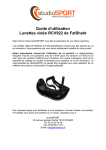
TBS GROUNDSTATION Compact take-anywhere integrated video groundstation Revision 2014-02-04 The TBS GROUNDSTATION is a compact, light-weight and all-in-one versatile "take anywhere" device. The small size and integrated display makes this the perfect tool for holding safe flights together with a spotter. It also lets spectators get a chance to watch what's going on. All while the pilot is using securely locked goggle cables. Dual-video outputs and a VTx port allow for extra goggles and external recorders, receivers and more. The integrated video receiver is compatible with most 2.4GHz transmitters. Key features ● Integrated 2.4 GHz 8-channel receiver with dual band support ● Bright 4-inch 4:3 LCD display with external on/off switch ● 2x RJ45 locking video outputs (video, audio, +5V, +12V) ● External VTx port for local re-broadcast of FPV signal ● 2x cinch (RCA) video outputs and DC power socket ● Auxiliary +5V USB port for charging GoPro’s, goggles or mobiles ● Connect any high-capacity 3S LiPo battery, XT60 connector ● Low battery voltage warning ● Tripod and antenna friendly mounts 1 About The TBS GROUNDSTATION was designed to be minimalistic, easy to setup, and wire-free. Having this in mind from the start made us focus on developing a compact device with only the most essential. TBS has years of experience setting up and preparing for FPV flights, this has allowed us to sift through tons of equipment and garner only the most suitable components. The end result is a groundstation which we use every day when we want to fly FPV. Perfection is achieved, not when there is nothing more to add, but when there is nothing left to take away. — Antoine_de_Saint-Exupéry , French aristocrat, writer, and pioneering aviator 2 Specifications Type: Dedicated groundstation, aluminium frame Display: LCD, 4-inch, LED-backlight, 4:3 aspect ratio, 480x360 pixels , matte finish Receiver: 2.4 GHz video receiver, 8-channel, dual band support (Lawmate/Boscam/IRC) Receiver sensitivity: -86dBm Video outputs: 75 Ohm Audio outputs: 10k Ohm Power consumption: 5W (11.1V 500mA) with display turned on Battery support: 11.1V (3S) LiPo pack, XT60-connector, 1500-5000mAh recommended External DC jack: Battery voltage (3S) - for goggles only USB charging: +5V 1A continuous Tripod mount: 2x 1/420 UNC thread (standard camera mount) Antenna mount: 2x M3 thread Working temperature: 0 - 40°C Dimensions: 106 (W) x 86 (H) x 44 (D) mm Weight: 458g Connections: 1x SMA-male antenna, 1x XT60 battery connector, 2x goggle locking ports, 2x RCA video out, 1x DC power socket, 1x VTx port, 1x USB charging port, 1x display power switch, 1x channel selector Kit contents: 1x Groundstation, 1x RJ45-to-Fatshark cable, various nuts & bolts 3 Suggested equipment If you are just getting into the hobby or want to get compatible parts without much fiddling around, consider the following components. Use the suggested equipment list as a “shopping list” if you are just getting started. Any existing gear you already own (e.g. 2.4GHz Rx antennas, 1.2GHz/5.8GHz VTx, chargers, batteries, cables) can be used with the TBS GROUNDSTATION. The following equipment, with the exception of the camera tripod, is available from Team BlackSheep. Camera tripods are available from big electronics/photography wholesalers or Ebay. Antenna: TBS 11dB Yagi (up to 10km range) FPV transmitter: Lawmate 2.4GHz 500mW video transmitter (on model) Local transmitter: TBS GREENHORN 5.8GHz 25mW video transmitter (for re-broadcast) FPV goggles: FatShark Dominator video glasses Battery: TBS GROUNDSTATION LIPO 3S 5000mAh pack or, any quality 3S 1500-5000mAh battery Battery charger: Graupner Ultramat 14S (premium) or TBS B6AC 80W (budget) Cables: TBS GROUNDSTATION Fatshark locking cable for extra goggles Silicone 16AWG 50-100cm extension battery cable with XT60-connectors Accessories: Camera Tripod to mount your gear (e.g. Cullmann Primax 150) 4 Groundstation There are two key features that are unique to this groundstation. One is the RJ45 connector (two outputs). It carries video, audio, +5V, as well as +12V (battery voltage). This reduces the weight and complexity of the cables needed to drive video goggles from the groundstation. At the moment TBS is offering specially made cables for Fatshark goggles which have a RJ45 connector on one end and regular plugs in on the other, being secured by the tab locking mechanism on the groundstation end. The ultimate goal is to have video goggles that will just have direct RJ45-to-RJ45 connection, removing the last few bulky plugs entirely. We are encouraging people to come up with modifications for their glasses and share them on fpvlab.com. The second new feature is the VTx port, which can power an external video transmitter (on another frequency, e.g. 5.8GHz) with any antenna for re-broadcasting the video feed locally. This makes it easy for fellow pilots or bystanders to tune in on the feed. Any device with a suitable video receiver (wireless DVR, receivers, screens, goggles, etc.) can all grab the video feed, untethered to the groundstation, and follow the flight. Because the signal path is analog there is virtually zero latency. The LCD screen is 4-inches and it can be turned on and off to save power. It works in the brightest of daylight thanks to the LED-backlight. All the display settings have been tweaked beforehand for maximum picture quality. Putting a small display on the groundstation makes it perfect for portable use and travelling. For instance, a two person crew can effectively work together to coordinate flight paths; one piloting the model while the other is guiding the antenna and watching the surroundings. The screen goes into blue-screen but it is the good kind of blue-screen which only shows up when the unit is powering up and when there is absolutely no sync signal to hook on to (only white noise). There is a USB port (+5V 1A) which can handle charging of GoPro’s, DVR’s, goggles or mobile phones. This is a great for extended flying sessions out in the field or remote areas. Be sure to charge your friends for use of the charging port :) The size of the device is close to the size of a regular Lawmate receiver, around twice as thick (or about the size of an oldskool walkman). The housing is all aluminum and works as a very effective RF-shield. There are two points for mounting the GROUNDSTATION to a tripod (bottom and back) and also two mounting points for attaching a TBS Yagi, patch or helix antenna. The kit includes a thumb screw for mounting it to the back of antennas equipped with tripod mounting brackets (e.g. patch antennas.) All switches and connectors are recessed as much as possible to prevent damage during transport or storage. 5 TBS GROUNDSTATION Note: Illustration not to scale Installation diagram Channel switches Antenna mount rev. 01.2014 - by ivc.no/tbs Wireless DVR, goggles DC power socket Cinch (RCA) video outputs (2x) SMA-female antenna socket Tripod and antenna mounts 4-inch LCD RJ45 goggle connections (2x) TBS 5G8 25mW GREENHORN Video Audio GND +5V 5V video transmitter port Display power switch XT60 XT60-female battery connector TBS GREENHORN TBS ROOKIE VTx TBS GROUNDSTATION USB charging port Tripod mount TBS GROUNDSTATION LIPO RJ45 connection Goggles Either Antenna 2.4GHz (any kind, here Yagi) Either Regular connection DVR, display, splitter Extra goggles Devices 3S 11.1V 5000mAh LVP Operating groundstation The following sections will show you the essential steps to get the groundstation up and running. After the initial configuration, it should only take you a minute to get set for flight. Mounting groundstation The groundstation has two metal threaded camera mounting points on the bottom and rear of the unit. These are standard 1/4-20 (1/4-inch diameter, 20 threads per inch) screw thread found on most cameras. If your tripod has a separate mounting-plate, take it off and attach it onto the bottom of the groundstation, or spin the groundstation a few times to get it mounted securely. Always detach the antenna and carry your groundstation by the tripod legs or stand to minimize mechanical stress on the mounting points and housing. 6 Connecting battery On the left side of the groundstation is an XT60-male port for connecting the battery. If you use the groundstation standalone, use velcro to attach the battery on the bottom side of the unit. Or on a tripod, use fairly long twisted 16AWG silicone extension wires to mount it low to the ground for better balancing/CG. The low battery voltage warning will sound when the preset 10.8V threshold (3.6V per cell) has been crossed. This is a good time to fly back and land safely. It is recommended to use batteries with built-in protection circuitry (e.g. TBS GROUNDSTATION LIPO) in addition to the low voltage alarm. Normal flight packs do not include this circuitry. Display configuration The 4-inch display has been preconfigured for quick start-up and automatically detects the format of video signal (PAL/NTSC). The brightness and contrast has been optimized to be used even on the most sunny days and is preloaded from the factory (no chance of messing it up). Turning the display on and off is done by sliding the switch on the left side of the unit. This controls only the power to the display itself, the rest of the system is powered independently of the switch. Note that the display starts up with a blue-screen and goes to only blue-screen when there is nothing but white noise left to screen. It “flies” through major static and will not go into blue screen. 7 Connecting antenna The antennas you build or purchase should be tuned for the range of channels shown in the table in the next section. It should also have a regular SMA-male connector with a center pin (not RP-SMA). The antenna coax cable connects to the SMA-male connector on the left side of the unit. Avoid excessive bends and turns as this can have a detrimental effect on the cable’s RF characteristics. To make it easier to handle the groundstation with an antenna attached, there are two dedicated mounting points for the antenna. The holes are standard M3 thread but should not go further than 5mm into the case. The TBS Yagi antenna will fit directly on the rear or top mount and we have provided thumb screws for the Yagi and attaching the unit on the back of antennas which have tripod mounting brackets (e.g. patch antennas.) Receiver channel switching Changing the channel of the 2.4GHz video receiver is primarily done through the 8-DIP switches on the top of the groundstation. Try to find a matching frequency band (Lawmate/Airwave/Boscam/IRC), transmitter frequency and antenna frequency (resonating range) for best picture quality and range. Only one DIP-switch toggle pin should be in the ON-position at a time. Switching channel can be done while power is applied. 8 The layout of the channel selection for the bands is shown in the following table. Fields marked with a star (*) indicates a band offset. Channel Band 1 Lawmate (MHz) Band 2 - Airwave / Boscam / IRC (MHz) Switch position (display facing you) 1 2410 2414 * 10000000 2 2430 2432 * 01000000 3 2450 2450 00100000 4 2470 2468 * 00010000 5 2370 2370 00001000 6 2390 2390 00000100 7 2490 2490 00000010 8 2510 2510 00000001 Channel 1 to 4 will be inside the ISM band, and should therefore not be used on R/C fields or in congested areas. Channels 5 - 8 are mostly safe to use in terms of interference. Note that you can not use a 2.4GHz R/C radio/transmitter together with this groundstation (or video transmitter). In this case use either 36MHz, 72MHz, 433MHz (UHF), or 5.8GHz to control your model and disable the RF module. Swapping band is done by soldering a bridge on the board inside the device (like on the TBS CORE), but this is strictly not necessary if you are not expecting to use any of the 3 offset-channels (see above). Frequency band selection 1. Lawmate ○ 2. Airwave/Boscam/IRC ○ 9 All unbridged (CH0, CH1, CH2) Bridge CH0 Connecting goggles One of the new exciting features of the groundstation is the compact and secure RJ45 goggle connection. The provided RJ45 cable is compatible with Fatshark FPV glasses. Simply click the connector in place, hook up the goggles on the other end and you are set! The cable carries video, audio, +5V (filtered) and +12V (battery voltage), which means that most existing glasses (Fatshark, Cinemizer, Vuzix, HeadPlay) can be made to work by modifying the cables. See following pinout of the RJ45 connector if you want to carry out the cable modification. Any CAT5/6 will work. TBS GROUNDSTATION RJ45 Pin-out 1. +5V filtered 2. GND for +5V 3. Video signal 4. GND for video 5. Audio signal 6. Not connected 7. Cable OK return line (yellow LED) 8. +12V (LiPo) after diode drop In addition to the two RJ45 ports for connecting goggles the easy way, there is a single DC power jack (battery voltage) and cinch (RCA) video output in case you have a second pair of goggles but no RJ45 cable on hand. The last cinch video output can be used for video recorders or other video equipment. There is no audio output available when using cinch cables. Note that the DC power jack is only meant for driving goggles. 10 Video transmitter port Another great new feature is the dedicated video transmitter (VTx) port on the right side of the unit. By connecting a video transmitter with a different frequency band (i.e. not 2.4GHz, ideally the TBS GREENHORN 5.8GHz 25mW), the FPV signal can be re-broadcasted locally. All untethered to the groundstation, leaving it dedicated to do what it was supposed to do; assisting the pilot uninterrupted. The port is compatible with TBS GREENHORN 5.8GHz 25mW, TBS ROOKIE 5.8GHz 200mW (sold separately) and any other low power +5V video transmitter. It connects using a Molex Picoblade 4-pin connector and the pigtail cable is normally supplied with the transmitter kit, plug&play! The output voltage is fixed at +5V and is only meant for transmitters with output power up to 200mW. The pin-out is according to the following color scheme (top to bottom on VTx socket): ● Yellow = Video ● White = Audio ● Black = GND ● Red = +5V filtered 11 USB charging port On the bottom-right side is a high-current +5V 1A USB port for charging devices in the field. The port is a regular full-sized USB host-socket. Note that this is only a charging port and no configuration or firmware upgrade facilities are available at this time. To avoid straining the connector, use velcro to attach a container on top of the groundstation to gather the devices (turned off to limit interference of course). Complete After the initial setup and cable management, everything should be fairly tidy and clean. Now go fly and enjoy your new groundstation! 12 During flight Your spotter should let you know of any changes in the environment close to you and in the area around the model. Let the spotter move and realign the receiver antenna when the picture begins to degrade. Keep as much separation between groundstation (receiving end) and R/C controller (transmitting end), minimum 1 meter. This is true even when you are using two different frequency bands, specially when using UHF transmitters. Always keep a spare backup battery pack ready in case there is a unexpected voltage drop (bad LiPo pack) and the low voltage warning is activated. Should the goggles stop working or cable is disconnected unexpectedly, be sure to be ready to fallback to the 4-inch display to land safely. Place your groundstation (and antenna) as far away from powered electronic and metal components as possible. Any metallic surface will reflect radio waves and reduce your receiving sensitivity/range. 13 Good practices We have compiled a list of all of the things that have been tried and tested in countless environments and situations by TBS crew and other experienced FPV pilots. Follow these simple rules, even if rumors on the internet suggest otherwise, and you will have success in FPV. ● Start with the bare essentials and add equipment one step at a time, after each new equipment was added to proper range- and stress tests. ● Do not fly with a video system that is capable of outperforming your R/C system in terms of range. ● Do not fly with a R/C frequency higher than the video frequency (e.g. 2.4GHz R/C, 900MHz video). ● Monitor the vitals of your plane (R/C link and battery). Flying with a digital R/C link without RSSI is dangerous. ● Do not use 2.4GHz R/C unless you fly well within its range limits, in noise-free environments and always within LOS. Since this is most likely never the case, it is recommended to not use 2.4GHz R/C systems for longer range FPV. ● Do not fly at the limits of video, if you see noise in your picture, turn around and buy a higher-gain receiver antenna before going out further. ● Shielded wires or twisted cables only, anything else picks up RF noise and can cause problems. ● When using powerful R/C transmitters, make sure your groundstation equipment is properly shielded. ● Adding Return-To-Home (RTH) to an unreliable system does not increase the chances of getting your plane back. Work on making your system reliable without RTH first, then add RTH as an additional safety measure if you must. ● Avoid powering the VTx directly from battery, step-up or step-down the voltage and provide a constant level of power to your VTx. Make sure your VTx runs until your battery dies. ● Do not power your camera directly unless it works along the complete voltage range of your battery. Step-up or step-down the voltage and provide a constant level of power to your camera. Make sure your camera runs until your battery dies. ● A single battery system is safer than using two dedicated batteries for R/C and FPV. Two batteries in parallel even further mitigate sources of failure. ● For maximum video range and “law compatibility”, use 2.4GHz video with high-gain antennas. ● When flying with R/C buddies that fly on 2.4GHz, or when flying in cities, it is perfectly possible to use 2.4GHz video provided you stick to the channels that do not lie in their band (CH5 to CH8 for Lawmate systems, available from TBS). ● Do not use diversity video receivers as a replacement for pointing your antennas, diversity should be used to mitigate polarization issues. ● Improving the antenna gain on the receiver end is better than increasing the output power (except in RF-noisy areas). More tx power causes more issues with RF on your plane. 500mW is plenty of power! 14 ● Try to achieve as much separation of the VTx and R/C receiver as possible to lower the RF noise floor and EMI interference. ● Do not buy the cheapest equipment unless it is proven to work reliably (e.g. parts falling off, multitudes of bug fix firmware updates, community hacks and mods are a good indicator of poor quality and something you do NOT want to buy for a safe system). Do due diligence and some research before sending your aircraft skyward. 15 Troubleshooting ● Issue: Beeping on power-up Solution: Make sure the video transmitter and receiver is tuned to the same frequency. The Groundstation will beep if there is more than one channel or no channel at all selected. The video signal will be detected automatically when a signal is available. Manual written and designed by ivc.no in cooperation with TBS. 16