1
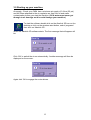
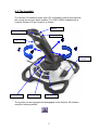
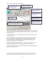
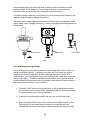
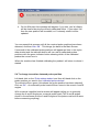
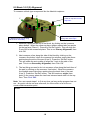
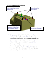
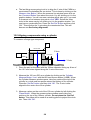
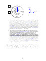
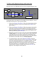
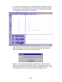
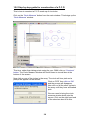
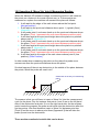
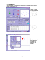
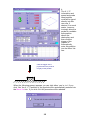
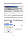
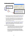
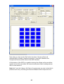
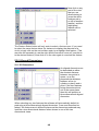
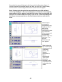
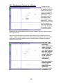
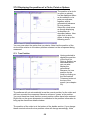
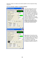
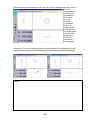
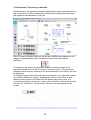
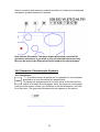
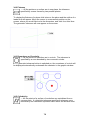
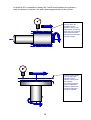
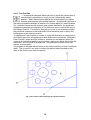
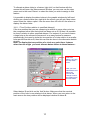
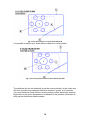
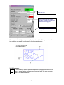
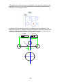
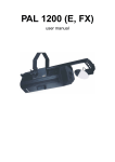
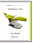
horizontal bar at the top selects B axis position and the vertical bar at the
bottom selects A axis position. This can also be done by using the two
selector boxes at the bottom left of the probe selector screen.
The Rack Position selector is only used if an auto-change rack is fitted to the
machine and will always default to position 1.
We also need to enter approximate values for the length and diameter of the
stylus being used. Roughly measure (+/-1mm) the length protruding below the
probe head:
PH10
R1
L
D
L
Stylus length
Stylus length
Stylus length
D
Fig.1
5.3 Calibrating probe positions
The first thing you need to do is determine probe direction (click on ball no. 1
within the picture-top left). ) angles you require by Then enter the stylus
length in the ‘stylus length box’ and the ruby ball diameter into the ‘ball
diameter box,’ you only need to enter stylus width in the ‘width box’ if you are
using a star stylus. To datum a probe position select the A (incline) and B
(rotationusing the drop down menus located in the bottom left hand corner of
the probe status window or the top sliders.
1. Press the ‘Add’ button in the right corner of the probe status window
you should then see a line in the ‘Datumed positions’ window showing
the probe position you want to calibrate.
2. If using a manual head a prompt will ask you to move the head.
3. Place the probe 50mm above the reference ball and left click on the
‘Start button’ in the probe status window, the machine will now
automatically measure a number of points around the reference ball.
12