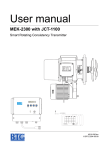
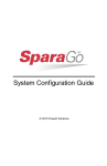
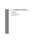
1
User Guide
Modbus Communications
for PanelView Terminals
Introduction
1
This document describes how to connect and configure
communications for the Modbus versions of the PanelView terminals.
This document provides supplemental information for the
PanelBuilder32 manuals.
For more information about:
Go to page:
Related Publications
2
Before using this Guide
2
Modbus Protocol
3
Modbus PanelView Terminals
3
Typical Modbus Network
4
Connector Pinout Definitions
7
Serial Port Connection
8
Modifying Modbus Settings from Terminal
9
Setting up Communications using PanelBuilder32
11
Modbus Address Spaces
14
Modbus Controller Data Table
15
Data Formats
16
Tag Editor
16
Downloading Applications over a Serial Link
19
Error Messages and Codes
20
Glossary
24
Publication 2711-6.9
2
Modbus Communications for PanelView Terminals
Related publications
The following documentation provides additional information on
installing, configuring and using your PanelView terminals.
Publication Titles
Number
PanelBuilder32 Getting Results Manual
2711-6.19
PanelBuilder32 Quick Start Manual
2711-6.20
PanelView Operator Terminal Manual
2711-6.1
The Modicon website provides information and product descriptions
of Modbus products at:
www.modicon.com
Before using this guide
We assume that you are familiar with Modbus communications. Since
we cannot provide specific information about every type of
application the PanelView might be used in, the information provided
in this document is general, rather than specific.
Refer to glossary at the end of this publication for definitions of
unfamiliar terms.
Publication 2711-6.9 - March 2000
Modbus Communications for PanelView Terminals
Modbus protocol
3
Modbus protocol links Modicon Programmable Controllers and
devices emulating Modicon Programmable Controllers in a wide
variety of applications. Modbus protocol defines a message structure
that controllers can use regardless of the network type over which
they communicate.
Modbus is a half-duplex, master-slave communications protocol. The
network master (PanelView) reads and writes coils and registers as if it
was a Modicon controller. Every device on a Modbus communication
link emulates the coils and registers of a Modicon Programmable
Controller. Modbus allows a host to read and write coils/registers and
obtain diagnostic information.
Modbus protocol allows a single master to communicate with a
maximum of 255 slave devices. The master device on a Modbus
network is not assigned an address.
Modbus PanelView
Terminals
Modbus terminals are identified by a 14 at the end of the catalog
number, for example 2711-K9C14.
The Modbus terminals have:
• Modbus communication port
• RS-232 printer/file transfer port
In addition, each terminal is available with either:
• AC or DC power
The characters L1 at the end of the catalog number designate a
terminal with DC power (e.g. -T9A14L1).
Publication 2711-6.9
4
Modbus Communications for PanelView Terminals
Typical Modbus Network
Shown below is a typical Modbus network with Modbus Controllers
installed on two of the network drops.
PanelView
Master Device
(1 per Network)
RS-232 Port
Modbus Port
RS-485/422
Computer for developing
PanelView applications
Serial Link
or
Printer
Modbus Programmable Controller
or Device Emulating a Controller
(Slave Device)
Modbus Programmable Controller
or Device Emulating a Controller
(Slave Device)
Modbus +
Publication 2711-6.9 - March 2000
Modbus Communications for PanelView Terminals
Connection to a Modbus
Plus Network
5
Using a Bridge Multiplexer (BM85) or an RF modem, the Modbus
PanelView can be connected to a Modbus Plus network.
Modbus Plus is a local area network supporting up to 64 nodes at a
data transfer rate of 1,000,000 bits/second. Modbus Plus provides host
level peer-to-peer communication for network devices. The network
also provides distributed input/output (DIO) communications.
The BM85 Bridge Multiplexer provides connection to a Modbus Plus
network through the PanelView Modbus RS-232 serial port.
Modbus
Modbus +
BM
85
RS-232
Port
Bridge Multiplexer
PanelView
Cable - PanelView to BM85
PanelView
BM85
2
3
3
2
4
5
6
7
8
9
5
Modbus
RS-232
Port
RF
Modem
RF
Modem
Modbus +
PanelView
Publication 2711-6.9
6
Modbus Communications for PanelView Terminals
Making Modbus
Connections
The PanelView Modbus protocol communicates with other devices
over an RS-232 (point-to-point) or RS-485/RS-422 (multi-drop) serial
link. Refer to the following pinout information to connect the
PanelView to a Modbus network.
Important: Follow the Modbus network layout and design as
specified by the user manual for your programmable controller.
PanelView
PanelView Modbus Connector
5
1
Line Termination
DIP Switch for RS-485/422
OFF
1
6
9
Refer to next page for a
description of pinout connections.
2
ON
Not Used
OFF = termination is off
ON = line terminated
Line Termination
The device at each end of an RS-485/422 network should be
terminated. A termination switch is provided on the PanelView (see
figure above). Enabling line termination provides an RC line
termination of .01mF and 120Ω. Do not use line termination for RS-232
communications. Do not terminate devices between the network
ends.
ATTENTION
!
Publication 2711-6.9 - March 2000
Use a nonconducting probe to change the line
termination switch. Do not use a graphite pencil or
other conductive material. Failure to use a
nonconducting tool, may result in damage to the
PanelView.
Modbus Communications for PanelView Terminals
Connector Pinout
Definitions
7
The communication type is downloaded with an application or is set
on the terminal configuration screen. The PanelView supports RS-232,
RS-485 and RS-422 communication standards. The Modbus 9-pin male
D shell connector has the following pin definitions for each standard.
Pin
Number
RS-232
Function
RS-485/RS-422
1
Shield
Shield
2
RXD
RXD 1 ,2
3
TXD
TXD
4
DTR
See note 3
5
COMMON
COMMON
6
DSR
See note 3
7
RTS
TXD
8
CTS
RXD 1,2
9
No Connection
No Connection
1. In RS-485 mode, pin 2 and pin 3 require an external jumper to electrically connect
pins 2 and 3.
2. In RS-485 mode, pin 7 and 8 require an external jumper to electrically connect pins 7
and 8.
3. These pins must remain unconnected.
Publication 2711-6.9
8
Modbus Communications for PanelView Terminals
Making Serial Port
Connections
Use the RS-232 serial port on the PanelView terminal to:
• download/upload applications over a serial link
• or to connect a printer
Computer
PanelView
COMM 1 or 2
RS-232 Printer/
File Transfer Port
Available Cables
2711-NC13 5 m (16.4 ft)
2711-NC14 10 m (32.7 ft)
2706-NC13 3 m (10 ft)
1
5
9
9 to 25 Pin Adapter
(if required)
6
9-pin female
1
2
3
4
5
6
7
8
9
9-pin male
1
2
3
4
5
6
7
8
9
Printer
RS-232
Port
PV300/600/900/1000/1400 Printer Port (DCE)
PV550 Printer Port (DCE)
9-pin male
9-pin male
1 NC
1 NC
2 RXD or TR1 (Data Receive)
2 RXD or RX1 (Data Receive)
3 TXD or TX1 (Data Transmit)
3 TXD or TX1 (Data Transmit)
4 NC
4 NC
5 COM
5 COM
6 DSR (pulled high to +12V)
6 DSR (pulled high to +12V)
7 RTS or RX2 (Data Receive)
7 NC
8 CTS or TX2 (Data Transmit)
8 CTS (pulled high to +12V)
9 NC
9 NC
Upload/Download or Printer Cable without Hardware Handshaking
PV550 Printer Port (DCE)
9-pin male
2 RXD or RX1 (Data Receive)
3 TXD or TX1 (Data Transmit)
5 COM
Publication 2711-6.9 - March 2000
Printer/Computer Port (DTE)
9-pin 25-pin
2
3
RXD (Data Receive)
2
3
TXD (Data Transmit)
TXD COM
5
7
Printer/Computer Port (DTE)
9-pin female
1 DCD
2 RXD (Data Receive)
3 TXD (Data Transmit)
4 DTR
5 COM
6 DSR
7 RTS
8 CTS
9 NC
Modbus Communications for PanelView Terminals
Modifying Modbus Settings
from the Terminal
9
You can display or modify Modbus settings directly from the terminal. From the
Configuration Mode menu of the terminal, select Serial Communication Setup. The
screen below appears.
ATTENTION
!
Settings downloaded with a Modbus application
have priority over terminal settings. Modbus settings
take effect immediately after an application is
downloaded.
MODBUS RTU MASTER
#############
Baud:
Data Bits/Parity:
Response Timeout (ms):
Port/Modem Handshake:
RTS TX Delay (ms):
RTS Off Delay (ms):
CTS Timeout (ms):
Restart
Terminal
9600
8/Odd
####
Modem
####
####
####
Error - ##
###
Exit
Reset Terminal [F1]
Resets the terminal.
Baud Rate [F2]
Steps through the available baud rates: 300, 1200, 4800, 9600, 19200,
28800, and 38400 with each key (or screen) press. A selected baud
rate takes effect immediately.
Parity/Data Bits [F3]
Steps through the available options:
• 8 EVEN
• 8 ODD
• 8 NONE (Default Setting)
Note: All communications occur with 1 stop bit.
Response Timeout (ms) [F4]
Opens the numeric entry scratchpad. Provide a timeout value of 20 to
5000 milliseconds. The timeout specifies the time, after a command is
sent by the PanelView terminal, that an error is indicated by no
response from the slave device.
Publication 2711-6.9
10
Modbus Communications for PanelView Terminals
Port/Modem Handshake [F5]
Steps through the available options:
• MODEM
• RS-232
• RS-422
• RS-485
Note: The following delays (RTS TX, RTS Off, and CTS Timeout)
facilitate modem communications. Refer to your modem user manual
for information on the recommended delay values.
RTS TX Delay (ms) [F6]
Opens the numeric entry scratchpad. Provide a delay value of 0 to
2000 milliseconds. The RTS TX delay specifies the delay between the
assertion of the RTS signal and the transmission of the first character
of the Modbus message.
RTS Off Delay (ms) [F7]
Opens the numeric entry scratchpad. Provide a delay value of 0 to
2000 milliseconds. The RTS Off delay specifies the delay between the
transmission of the last character of the Modbus message and the
assertion of the RTS signal.
CTS Timeout (ms) [F8]
Opens the numeric entry scratchpad. Provide a timeout between 0 to
2000 milliseconds. The CTS timeout specifies the maximum allowable
delay between the assertion of the RTS signal by the PanelView
terminal and the assertion of the CTS signal by the modem.
Exit [F10] or [F16]
Returns to the Configuration Mode menu.
Publication 2711-6.9 - March 2000
Modbus Communications for PanelView Terminals
Setting up Communications
11
Setting up Modbus communications for an application includes:
• selecting a Modbus terminal when creating the application.
• configuring communication parameters for the terminal on the
Modbus link.
Selecting a Modbus PanelView Terminal
Select a Modbus terminal for a PanelView application from:
• Create New Application dialog or the
• Terminal Setup tab of the Application Settings dialog when
converting the application to run in another terminal.
Any catalog number with 14 as the last number (2711-xx14) is a
Modbus terminal.
Indicates RS-232 port is set
for downloading
applications not printing
Publication 2711-6.9
12
Modbus Communications for PanelView Terminals
Configuring Modbus Communications
Modbus communication parameters are accessed from the Terminal Setup dialog.
To open the Terminal Setup dialog, choose Terminal Setup from the
PanelBuilder32 Application menu.
If RS232, RS422, or RS422 Port Configuration is selected
If Modem Handshaking is selected
1. Click the Comms. Setup button from the Terminal Setup dialog.
2. Under Network Devices, edit the following parameters:
Publication 2711-6.9 - March 2000
Specify:
To:
Node Name
Either select a previously defined network node name or
enter a new name of up to 32 characters. The name is
validated when you click the OK to make sure it has not
been previously assigned to another PanelView in the
same project.
Node Address
Select the address (1 to 255) of the slave device on the
Modbus link. This address is associated with the network
device selected in the Name field (above). Each node on
the network should be assigned a unique address.
Type
Select Modbus as the type. You cannot create or modify
the configuration of a device with a Type defined as Other
(not Modbus).
Modbus Communications for PanelView Terminals
13
3. Under Terminal, edit the following parameters:
Specify:
To:
Slave Response
Timeout (msec)
Enter a value between 20 and 5000 milliseconds. The
default is 250. This timeout specifies the time, after a
command is sent by the PanelView terminal, that an error
is indicated by no response from the slave device.
Baud Rate
Select the baud rate of the Modbus link. The available
baud rates are:
300
1200
4800
9600 (Default Setting)
19200
28800
38400
Data Bits/Parity
Select Number of Data Bits and Parity:
8/ODD
8/EVEN
8/NONE (Default Setting)
Note: Serial communications occur with 1 stop bit.
Port Configuration/
Modem Handshaking
Select the communication port option:
RS232 (Default)
Modem
RS422
RS485
The Following Only Appear when Modem is Selected
RTS TX Delay (msec)
Enter a value between 0 and 2000 milliseconds. The
default is 0. This delay occurs between the asserting of
RTS and the transmission of the first character of data.
RTS Off Delay (msec)
Enter a value between 0 and 2000 milliseconds. The
default is 0. This delay occurs between the last data
character transmitted and the deasserting of RTS.
CTS Timeout (msec)
Enter a value between 0 and 2000 milliseconds. The
default is 100. This timeout specifies the delay between
the assertion of the RTS signal by the PanelView terminal
and assertion of the CTS signal by the modem.
4. Click OK to exit and return to the Terminal Setup dialog.
Publication 2711-6.9
14
Modbus Communications for PanelView Terminals
Modbus Address Spaces
The PanelView reads and writes data into other Modbus devices on
the same network. The Node Address specifies the device (node) and
the Address Type specifies the address space. The following address
types are supported:
• Input Status (status of Modicon controller discrete input)
• Output Coil (status of Modicon controller discrete output)
• Input Register (contents of input register in Modicon controller)
• Holding Register (contents of holding register in Modicon
controller)
Modbus devices can contain four distinct address spaces. Two spaces
are reserved for Coil data and two are reserved for Register data. The
PanelView terminal can read from any of the four address spaces.
However, the PanelView terminal can only write to the Output Coil
and Holding Register address spaces.
Coil Addressing
In Write Tags
If Output Coil address type is specified in a write tag, the data is
written to the Coil address using Modbus Function Code 5 (single coil)
or Function Code 15 (multiple coils).
In Read Tags
If either Coil address type is specified in a read tag, data is read from
the appropriate Coil address. For Input Status Coils, the status of the
discrete input is read using a Modbus Function Code 2. For Output
Coils, the status of the discrete output is read using Function Code 1.
Register Addressing
In Write Tags
If Holding Register address type is specified in a write tag, data is
written to the Register address using Modbus Function Code 6 (single
register) or Function Code 16 (multiple registers).
In Read Tags
If an Input Register or Holding Register is selected in a read tag, data
is read from the appropriate Register address using Modbus Function
Code 3 (holding register) or Function Code 4 (input register).
Publication 2711-6.9 - March 2000
Modbus Communications for PanelView Terminals
15
Data and Address Types
Not all of the data types are compatible with every address type. The
following table shows the Address Type available based on the
selected data type.
Modicon Controller Data
Table
Data Type
Compatible Address Type(s)
Bit
Input Status, Output Coil
4BCD
All Address types
Unsigned Integer
Input Register, Holding Register
Signed Integer
Input Register, Holding Register
IEEE Float
Input Register, Holding Register
Bit Array
Input Status, Output Coil
Character Array
Input Register, Holding Register
Modicon controllers store read and write address spaces in the
following data table locations.
Note: The PanelView does not require data addresses that conform to
the address ranges provided in the following table. For each address
type, the PanelView terminal supports address ranges from 0 to 65535.
For example, for a discrete input status at address 40000, the full
address representation would be 140000.
Address
Address Type
Data Access
Description
0xxxxx
Discrete Output
or Coil (Internal)
Bit Read or Write
Use to drive a real output through an output module or to
set one or more internal coils.
A coil can be used to drive multiple contacts.
1xxxxx
Discrete
Input Status
Bit Read Only
Use to drive contacts in the logic program. The Input state
is controlled by an input module.
3xxxxx
Input Register
Word Read Only
Holds numeric inputs from an external source (for
example, a thumb wheel entry, an analog signal or data
from a high speed counter). A 3x register can also store
16 contiguous discrete signals that are entered into the
register in either binary or binary coded decimal (BCD)
formats.
4xxxxx
Output
Holding Register
Word Read and
Write
Use to store numerical (decimal or binary) information or
to send the information to an output module.
6xxxxx
Extended
Memory Register
Access through
Logic Program only
Use to store information in an extended memory area.
Only available in PLCs with 24 bit CPUs that support
extended memory such as the 984B, E984–785 and
Quantum series of PLCs.
Publication 2711-6.9
16
Modbus Communications for PanelView Terminals
Data Format
Modicon controllers communicate in either ASCII or RTU (Remote
Terminal Unit) transmission mode. The PanelView only supports RTU
mode. In RTU mode, each 8-bit byte contains 2 four-bit hexadecimal
characters. The following is supported:
• 1 start bit
• 8 data bits (least significant bit first)
• 1 bit for even/odd parity, no bit for no parity
• 1 stop bit if parity used, 2 bits if no parity selected
PanelBuilder32 Tag Editor
Use the Tag Editor or the Tag Form dialog (accessed from the object’s
dialog) to enter tags. There are 2 types of tags:
• digital - for bit data types
• register - for all other data types
Tag Editor
Register Tag Form Dialog
Publication 2711-6.9 - March 2000
Bit Tag Form Dialog
Modbus Communications for PanelView Terminals
17
Tag Editor Fields
Field
Description
Valid Characters
Notes
Tag Name
Name of tag.
Maximum characters = 32
A-Z, a-z, 0-9
hyphen (-), underscore (_),
percent (%)
- Tag name must be unique.
- Can’t start with 0-9, hyphen, or percent
- Tag names are not case sensitive.
- Do not use blanks, tabs, carriage returns
or non-printable characters.
Data Type
Data format of tag.
Select one of the following:
Bit
4BCD
Unsigned Integer
Signed Integer
IEEE Float
Bit Array
Character Array
Data type must be compatible with the
data format selected in the object’s
dialog.
Array Size
Size of array.
Character arrays are 1-128
characters
Bit arrays are 1-16 bits
- Displays only if Bit Array or Character
Array are selected.
- Array size must be an integer.
- A Modbus bit array can start at any input
or coil address regardless of the word
boundaries.
- Do not use blanks, tabs, carriage returns
or non-printable characters.
Description
Description of tag.
Maximum characters = 255
Any printable character
Do not use tabs, carriage returns or
non-printable characters.
Node Name
Name of node (device) assigned to tag.
Pull down list of previously
defined nodes.
Each node name is associated with a
node address.
Tag Initial Value
The starting value for the current tag in
engineering units (used only for write
tags).
Maximum characters = 24
0-9
e, E, +, - and period
0 or 1 for bit data type
- Do not use blanks, tabs, carriage returns
or non-printable characters.
- Maximum precision is 6 places to the
right of the decimal point for non-floating
point values.
- If present, a sign (+ or -) for the number
must be first (+ is default).
- If present, a sign for the exponent must
immediately follow the e or E.
- No entry = default of 0.
Tag Address
Address of the data in the slave device.
0 to 65535
- Do not use blanks, tabs, carriage returns
or non-printable characters.
- A Modbus bit array can start at any input
or coil address regardless of the word
boundaries.
Publication 2711-6.9
18
Modbus Communications for PanelView Terminals
Field
Description
Valid Characters
Notes
Type
Determines address of the data in the
slave device.
Options are:
Input Status
Output Coil
Input Register
Holding Register
Address Type may support some or all of
the data types. Refer to page 15.
Scaling
Scale:
‘m’ in y = mx + b
Offset:
‘b’ in y = mx + b
Values you want to use to convert the
current tag’s processor integer value (‘x’)
to engineering units (‘y’).
Maximum characters = 12
0-9
e, E, +, and period
- Do not use blanks, tabs, carriage returns
or non-printable characters.
- Maximum precision for scale is 6 places
to right of decimal point.
- Maximum precision for offset is 6 places
to right of decimal point.
- If present, a sign (+ or -) for the number
must be first (+ is default).
- If present, a sign for the exponent must
immediately follow the e or E.
Data Entry Limits
Minimum
Maximum
Minimum and maximum values that can
be assigned to the tag.
Maximum characters = 12
0-9
e, E, +, and period
- Do not use blanks, tabs, carriage returns
or non-printable characters.
- Maximum precision is 6 places to right
of decimal point.
- If present, a sign (+ or -) for the number
must be first (+ is default).
- If present, a sign for the exponent must
immediately follow the e or E.
Publication 2711-6.9 - March 2000
Modbus Communications for PanelView Terminals
Downloading Applications
over a Serial Link
19
To download a Modbus application from your computer to the
PanelView terminal over an RS-232 link:
• connect computer to RS-232 port of PanelView terminal
• download application from the PanelBuilder32 File menu
Downloading Application using the Internal DF1 Driver
This section shows how to download an application from a serial
COM port on your computer to the RS-232/DF1 port of the PanelView
terminal using a point-to-point connection. The download uses the
internal DF1 driver on your computer’s COM1- COM9 port. This driver
uses fixed DF1 settings that match those of the RS-232 port of the
terminal. Use the 2711-NC13 cable (9-pin connector) for the
point-to-point connection. Check the cable connections before
starting the download.
Open the application you want to download and select
File>Download. The application is validated during the download.
Any errors that occur during validation must be corrected before you
can proceed with the download.
Name of application
being downloaded
Starts the
download
Select a COM port
for the download
These are default settings that
must match the fixed settings of the
Panelview terminal.
When the download is complete, the terminal resets, verifies and starts the
application.
Publication 2711-6.9
20
Modbus Communications for PanelView Terminals
Modbus Application Report
The application printout for Modbus provides the following
information:
• configuration data
• tag data
Error Messages and Codes
The following tables lists error messages and codes specific to
Modbus communications. For all other messages, refer to the
PanelView Operator Interface manual or the PanelBuilder32 online
help.
PanelBuilder32 Tag Error Messages
Message
Recommended Action
Tag Address is invalid, number must be between 0 and 65535.
Enter appropriate value (0–65535) in Tag Editor.
Character Array Size is invalid, must be between 1 and 128.
Enter appropriate value (1–128) in Tag Editor.
Maximum separation of coil tags in an alarm must be less than In Alarm Setup, change the alarm callout tags so that their
1024 coils.
addresses are within the specified number of coils/registers of
the alarm trigger tag address.
Maximum separation of register tags in an alarm must be less
than 64 registers.
In Alarm Setup, change the alarm callout tags so that their
addresses are within the specified number of coils/registers of
the alarm trigger tag address.
All tags in an alarm must reference the same network node
address.
In Alarm Setup, change the alarm trigger tag and
corresponding alarm callout tags to correct the error condition.
All tags in an alarm must have the same Modbus address type. In Alarm Setup, change the alarm trigger tag and
corresponding alarm callout tags to correct the error condition.
All tags in an alarm must be in the same direction to/from the
network node.
In Alarm Setup, change the alarm trigger tag and
corresponding alarm callout tags to correct the error condition.
There cannot be more than one tag in an alarm if the data
direction is to the network node.
In Alarm Setup, change the alarm trigger tag and
corresponding alarm callout tags to correct the error condition.
Cannot write to an input register or input status address.
Use an output tag for an object or change the tag
addresses in the Tag Editor to an output register or coil.
Not enough network address space to support a tag of this
data type.
Change the tag address to reference a lower numbered
discrete address or register.
Publication 2711-6.9 - March 2000
Modbus Communications for PanelView Terminals
21
The following errors are not specific to Modbus but may appear when
you exit the Tag Editor.
Message
Recommended Action
Minimum Value is invalid, must be between 0 and 9999
Enter appropriate value in Tag Editor.
Minimum Value is invalid, must be between 0 and 65535
Enter appropriate value in Tag Editor.
Minimum Value is invalid, must be between –32768 and 32767
Enter appropriate value in Tag Editor.
Minimum Value is invalid, must be between –99999997952 and 999999995904
Enter appropriate value in Tag Editor.
Maximum Value is invalid, must be between 0 and 9999
Enter appropriate value in Tag Editor.
Maximum Value is invalid, must be between 0 and 65535
Enter appropriate value in Tag Editor.
Maximum Value is invalid, must be between –32768 and 32767
Enter appropriate value in Tag Editor.
Maximum Value is invalid, must be between 0 and 9999
Enter appropriate value in Tag Editor.
Scale Value is invalid, must be between –99.999997952e9 and 999,999995904e9
Enter appropriate value in Tag Editor.
Offset Value is invalid, must be between –99.999997952e9 and 999,999995904e9
Enter appropriate value in Tag Editor.
PanelBuilder32 Node Error Messages
Message
Recommended Action
Slave Response Timeout is invalid, must be between 20
and 50000.
Correct value in the Communications Setup Dialog.
RTS TX Delay is invalid, must be between 0 and 2000.
Correct value in the Communications Setup Dialog.
RTS Off Delay is invalid, must be between 0 and 2000.
Correct value in the Communications Setup Dialog.
CTS Timeout is invalid, must be between 0 and 2000.
Correct value in the Communications Setup Dialog.
Node Address is invalid, must be between 1 and 255
Correct value in the Communications Setup Dialog.
Data Bits / Parity is invalid.
Correct value in the Communications Setup Dialog.
Port Configuration / Modem Handshaking is invalid.
Correct value in the Communications Setup Dialog.
Baud Rate is invalid.
Correct value in the Communications Setup Dialog.
Terminal node not configured.
Configure the node in the Communications Setup Dialog.
Network node is invalid, must be Modbus type.
Configure the node in the Communications Setup Dialog.
PanelBuilder32 Translation Error Messages
Publication 2711-6.9
22
Modbus Communications for PanelView Terminals
Message
Recommended Action
Not enough network node address space to support a tag of this
data type.
Change the tag address to reference a lower
numbered discrete address or register.
Not enough RAM on Daughtercard to support the size of this user
application file.
Group tag addresses together as much as
possible, otherwise remove screen objects.
Translation Failure
Contact Allen-Bradley for technical support.
Publication 2711-6.9 - March 2000
Modbus Communications for PanelView Terminals
23
Communication Status Error Messages
These errors appear as a banner at the top of an application screen
(error #634 in upper left corner) or as a status display on the terminal
configuration screen.
Note: Since the PanelView is configured as a master device,
communication status is not updated until the PanelView requests
information. If communications are lost, the PanelView displays the
last communication status.
Errors numbered less than 7 are considered minor fault conditions and
will clear automatically when corrected. Errors numbered 7 and above
require that the terminal be reset to clear the error.
Code
Indicates
Recommended Action
1
No connections established. Occurs on power–up
until a device connection is established on the
network.
Establish a connection over Modbus to the
PanelView.
2
Invalid Messages (Parity Error). The Parity received by the
PanelView is invalid.
Check that the parity of both the PanelView
terminal and Modbus device are set the same.
3
Error Reply Messages (Application Error). Error indicates Verify the coil and register addresses used in
that the Modbus device does not support a coil or register the application.
address requested by the PanelView terminal.
4
Error Detect Failures (CRC Error). Indicates that the
messages from a Modbus device contain an invalid Cyclic
Redundancy Check.
Verify the address of each Modbus device and
cabling to each device.
5
Loss of Communications (Rx Timeout). Indicates Modbus
device is not responding.
Verify that the Modbus device supports RTU
communications.
6
Modem Failure (CTS Timeout Failure). Indicates that the
modem failed to assert the CTS line within the time
specified on the configuration screen.
Check the cabling and, if necessary, increase
the CTS timeout on the communications
configuration screen.
7-22
Internal Errors
Reset Terminal, Contact Allen–Bradley
technical support if problem reoccurs.
Publication 2711-6.9
Glossary
Coil
Bit location in a a Modbus device.
Digital Tag
A bit address.
Inputs
Data which is received by the logic controller from other devices.
Master
Device which sends messages (queries) to one or more slave devices.
Modicon Controller
Refers to the 184/384, 484, 584, 884, M84 (micro), or 984 family of
Modicon logic controllers.
Outputs
Data which is sent by a logic controller to other devices.
Register
16 bit unsigned value residing in a Modbus device.
RTU
Acronym for Remote Terminal Unit, one of 2 possible transmission
formats supported by Modbus. PanelView terminals only support
RTU.
Slave
Device which receives queries from the master and provides a
response.
Publication 2711-6.9 - March 2000 24
Supersedes Publication 2711-6.9 - October 1997
40061-386-01(B)
© Copyright 2000 Rockwell International Corporation. Printed in the U.S.A.