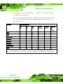
1
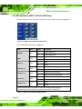
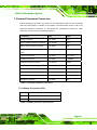
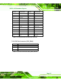
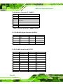
DRPC-100 Embedded System
C.1 Introduction
The DIO connector on the DRPC-100 is interfaced to GPIO ports on the Super I/O chipset.
The DIO has both 4-bit digital inputs and 4-bit digital outputs. The digital inputs and digital
outputs are generally control signals that control the on/off circuit of external devices or
TTL devices. Data can be read or written to the selected address to enable the DIO
functions.
NOTE:
For further information, please refer to the datasheet for the Super I/O
chipset.
C.2 DIO Connector Pinouts
The following table describes how the DIO connector pins are connected to the Super I/O
GPIO port 1.
Pin
Description
Super I/O Pin
Super I/O Pin Description
1
Ground
N/A
N/A
2
VCC
N/A
N/A
3
Output 3
GP27
General purpose I/O port 2 bit 7.
4
Output 2
GP26
General purpose I/O port 2 bit 6.
5
Output 1
GP25
General purpose I/O port 2 bit 5.
6
Output 0
GP24
General purpose I/O port 2 bit 4.
7
Input 3
GP23
General purpose I/O port 2 bit 3.
8
Input 2
GP22
General purpose I/O port 2 bit 2
9
Input 1
GP21
General purpose I/O port 2 bit 1
10
Input 0
GP20
General purpose I/O port 2 bit 0
Table C-1: Digital I/O Connector Pinouts
Page 141