1
A DISTRIBUTED SENSOR DATA MANAGEMENT INFRASTRUCTURE
BASED ON 802.15.4/ZIGBEE NETWORKS
by
TIANQIANG LI
Presented to the Faculty of the Graduate School of
The University of Texas at Arlington in Partial Fulfillment
of the Requirements
for the Degree of
MASTER OF SCIENCE IN COMPUTER SCIENCE AND ENGINEERING
THE UNIVERSITY OF TEXAS AT ARLINGTON
December 2006
ACKNOWLEDGEMENTS
I would like to take the opportunity to express my appreciation to my
supervising professor Dr. Yonghe Liu for his constantly motivating and encouraging me,
and for his invaluable advices during the course of my master thesis studies. And he
also keeps giving me the considerate and comprehensive supports on my requirements
regarding to hardware, software, technical support and communications. All of these are
the strong momentums that greatly drive me to overcome many difficulties that I met
during the course of thesis and get the research done on time.
I wish to thank Dr. Sajal K.Das and Dr. Ramez Elmasri for their interests in my
research, to be my thesis committee and assign their precious time to evaluate my
research.
I also wish to thank my teammate, PhD candidate Jun Luo for his interests in
my research and for the helpful discussions and invaluable comments which help me
find the correct direction in my research and make the progresses faster.
Special thanks should be given to my friends help me in many ways. Finally, I
would like to express my deep gratitude to my parents and brother for their
encouragement, patience and thoughtful concern.
November 9, 2006
ii
ABSTRACT
A DISTRIBUTED SENSOR DATA MANAGEMENT INFRASTRUCTURE
BASED ON 802.15.4/ZIGBEE NETWORKS
Publication No. ______
Tianqiang Li, M.S.
The University of Texas at Arlington, 2006
Supervising Professor: Yonghe Liu
Wireless sensor networks consist of a certain number of autonomous devices
with sensor, every device has certain detection functionality like light, temperature
pressure etc. Communication by using the radio frequency make these spatially
distributed devices feasible to oversee the activities in a large scale of area/space.
802.15.4/ZigBee networks are slated to run in the unlicensed frequencies. It is a
packet-based radio protocol aimed at very low-cost, battery-operated widgets and
sensors that can intercommunicate and send low-bandwidth data to each other.
iii
This thesis covers the content of a software solution of data management for an
802.15.4 networks. Its main contribution lies in it grounds a scalable and extendable
infrastructure for current and future developments to depend on, enabling users to
manage the distributed sensor data across the diversified and spacious ZigBee network.
Some unique technologies are proposed according to the specific hardware embedded
environment, such as cyclic queue, storage structure of RAM+Flash memory, Dynamic
binary search etc. Some improvement solutions are also implemented in an attempt to
fill the gaps in functionalities of ZigBee networks such as TCP/IP stacks built onto
ZigBee protocols. Some advanced design ideas are also presented such as browserbased user interface, communication via standard protocol (HTTP); Some software
implementations are accomplished for the first time without former references such as
the immigrating the RTX51 tiny from standard 8051 CPU to ChipCon2430 CPU.
The infrastructure that we proposed consists of the sensor data collecting
subsystem, data storing subsystem, data query algorithm and subsystem, radio
frequency intercommunication subsystem and browser based user accessing interface.
Sensor data collection and storing system will periodically save the sampled value from
sensor to the memory system and later to the permanent flash memory. Data query
subsystem will provide an efficient approach to locate the data to be queried among
large number of stored data. Radio frequency intercommunication subsystem is in
charge of the radio frequency communication between devices, to delivery back and
forth for the query request and response is the one of the major duties in this subsystem.
iv
The user accessing interface supports the users to submit query requests in the browser
with the standard http link address in users’ personal computer.
v
TABLE OF CONTENTS
ACKNOWLEDGEMENTS..............................................................................................ii
ABSTRACT ....................................................................................................................iii
LIST OF ILLUSTRATIONS........................................................................................... ix
LIST OF TABLES............................................................................................................ x
Chapter
Page
1. INTRODUCTION ........................................................................................................ 1
1.1 Outline................................................................................................................. 7
2. HARDWARE ENVIRONMENT................................................................................. 9
2.1 Overview............................................................................................................. 9
2.2 Hardware Summary on Chip Set ........................................................................ 9
2.3 Hardware summary of development board....................................................... 10
3. SENSOR DATA COLLECTING SUBSYSTEM ...................................................... 12
3.1 Overview........................................................................................................... 12
3.2 Relevant Hardware ........................................................................................... 12
3.3 Software Implementation.................................................................................. 12
4. SENSOR DATA STORAGE SUBSYSTEM............................................................. 14
4.1 Overview........................................................................................................... 14
4.2 RAM and Flash memory .................................................................................. 14
vi
4.3 Page Accessing and Cycle Queue..................................................................... 15
4.4 Caching and flashing ........................................................................................ 18
5. SENSOR DATA QUERY SUB-SYSTEM ................................................................ 19
5.1 Overview........................................................................................................... 19
5.2 Comparison of searching algorithms ................................................................ 19
5.3 Dynamic and static binary search ..................................................................... 21
6. RADIO FREQUENCY COMMUNICATION SUBSYSTEM .................................. 26
6.1 Overview........................................................................................................... 26
6.2 Overview of IEEE 802.15.4 and ZIGBEE........................................................ 26
6.3 Specification in CC2430 and Physics and MAC Layer.................................... 31
6.4 TCP/IP Protocol Implementation ..................................................................... 34
7. USER INTERFACE SUBSYSTEM......................................................................... 39
7.1 Overview........................................................................................................... 39
7.2 Browser-based interface ................................................................................... 39
7.3 Way to hookup.................................................................................................. 40
7.4 Processing within ZigBee network................................................................... 41
8. RESEARCH OF EMBEDDED OPERATING SYSTEM.......................................... 43
8.1 Overview........................................................................................................... 43
8.2 Overview of Embedded Operating System ...................................................... 43
8.3 Migrate to our system ....................................................................................... 44
8.4 Basic software architecture of RTX51 tiny ...................................................... 46
8.5 Stack Management in RTX51 tiny.................................................................... 49
vii
8.6 Initialization of RTX51 tiny.............................................................................. 50
8.7 Processing Diagram of Task Scheduling in RTX51 Tiny ................................ 51
9. PERFORMANCE TEST ON NETWORK COMMUNICATIONS .......................... 54
9.1 Overview........................................................................................................... 54
9.2 Test Environment and terms............................................................................. 54
9.3 Test Procedure .................................................................................................. 55
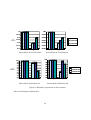
9.4 Test Result ........................................................................................................ 55
9.5 Experiment Analysis......................................................................................... 57
10. CONCLUSION AND FUTURE WORK ................................................................. 61
REFERENCES ............................................................................................................... 63
BIOGRAPHICAL INFORMATION.............................................................................. 66
viii
LIST OF ILLUSTRATIONS
Figure
Page
1
System Architecture.............................................................................................. 6
2
Picture of Development board .............................................................................. 11
3
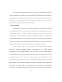
Cyclic Queue......................................................................................................... 16
4
Insertion operation of cyclic queue....................................................................... 17
5
Two cases in Splitting the window in cyclic queue.............................................. 23
6
ZigBee network model.......................................................................................... 31
7
Structure of User Interface Subsystem ................................................................. 39
8
Software structure in RTX51 tiny......................................................................... 48
9
Stack Management in RTX51 tiny ....................................................................... 50
10 Processing Diagram of Task Scheduling in RTX51 tiny (Part I).......................... 52
11 Processing Diagram of Task Scheduling in RTX51 tiny (Part II)......................... 53
12 Reliability comparisons in four scenarios.............................................................. 58
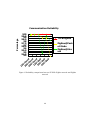
13 Reliability comparisons between TCP/IP+ZigBee and ZigBee network .............. 60
ix
LIST OF TABLES
Table
Page
1
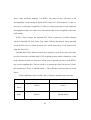
Comparison within Wi-Fi, Bluetooth and ZigBee .......................................... 28
2
Categories of ZigBee devices.......................................................................... 29
3
Important APIs in PHY& MAC layer libraries in Chipcon CC2430 ZigBee
solution ............................................................................................................ 33
4
Difference between 8051 and CC2430 in controlling time tick timer ............ 45
5
Experiment result when payload is 10 bytes................................................... 56
6
Experiment result when payload is 30 bytes................................................... 56
7
Experiment result when payload is 60 bytes................................................... 57
x
CHAPTER 1
INTRODUCTION
In the recent few years, the applications of sensor devices have been explosively
expanded in many areas like house appliances, automatic surveillance, environment
protection and military reconnaissance, etc. They come with not only a lot of diversified
sensor networks made by different manufactures, but also all kinds of different private
communication protocols. As there are more and more sensor networks being deployed
to the market, sooner or later, those networks will overlap with each other or face the
need of interacting with each other to interchange data. To interact with all these remote
sensor devices and sensor networks, there should be an industry standard to represent
the comprehensive requirements in personal-area network and let the manufactures
comply with it. Only in this way, the sensor network world can be unified to a healthy
growing way.
One of the most promising protocols is ZigBee, a software layer based on the
IEEE 802.15.4 standard. ZigBee is designed to satisfy the market’s need for a costeffective wireless home-area network that supports low data rates, low power
consumption, simplicity, security, and reliability, [1,2,3] introduce the standard
specification of IEEE 802.15.4, [4, 5, 6] presented ZigBee in terms of concepts and
protocols.
1
In the previous experiences, there are some challenges in different aspects that
we met when people were trying to create a software architecture or system to manage
the sensor data of ZigBee network. They are shown below:
1. ZigBee protocol lacks of traffic-intended consideration, even though ZigBee
is designed to be with low data rate, low power consumption, simplicity and security.
The capability of transmitting data is not strong enough to make it carry the large
amount of traffic like stream data, large-amount-data-generated sensor like video
camera.
2. The Address used to identify a node in ZigBee networks are a 16-bit number
or 64-bit IEEE address. Both of them are not compatible with the most widely-used IP
address, which means ZigBee network is not able to be a part of Internet, can not join
the IP network and be located directly from outside the ZigBee network without the
help of specific-designed gateway.
3. Most of sensor node didn’t largely store the history data. They either don’t
store history data at all, only keep the current sampled data in their storage system, or
do some aggregations or compressions real-timely, without storing the history data
piece by piece as they were. They do so because there are restrictions in memory space
in the earlier sensor node. Our system built on ChipCon 2430, which has 128K byte
flash memory and 8K byte RAM, in some extent it lifts the burden of storing more
details that we got. So figuring out a storage system to keep the data in permanent
storage efficiently and reliably, is one of the main challenge that we are facing.
2
4. With a existence of challenge No.3, we can easily expected further that there
are not many query algorithms and implementations available for system builder to
query the data within this large amount of sensor data. One of important task for us is to
get this question over with.
5. To design a system which is scalable and extendable, be good modularization?
These features are critical at the beginning stage of design procedure, a well-designed
architecture in these aspects will place solid and flexible groundwork for the upper
applications in the future, accommodate the problem revising and future upgrade with
no need to rebuild the original designed architecture.
6. Select and run a real time operating system onto our specific sensor nodes.
Chipcon2430 is quite new hardware released on the market, plus the fact that Chipcon
Corp. doesn’t have its own RTOS solution, both of issues lead to the fact that so far
there is no corresponding operating system for education purpose.
7. Providing the users a convenient access window to the users. Many sensor
network need uses install their own software onto users’ computers before their
functionalities can take effect, there should be a way to release the burden to the users
on this.
Facing these challenges, in this thesis, we proposed our corresponding solutions
to above challenges in respective chapter, all these solutions and other necessary
components make up of a distributed sensor data management software infrastructure.
For the challenge No.1 and 2, we build a TCP/IP stack on top of ZigBee stack,
offer the feature of reliable, connection-oriented data transmission into our ZigBee
3
networks, strengthen largely their capability to couple with the data traffic situations.
The retransmission and reassembly feature offered by TCP/IP also make our ZigBee
networks now are ideal to carry stream data. On the other hand, the IP stack identify
every sensor node with an unique IP address, the ZigBee network can be part of the
Internet or a subnet of Internet, the individual sensor node is able to be accessible and
located by using the standard IP routing protocol. Chapter 6 will give us detailed
descriptions regarding these. Chapter 9 gives readers a practical experiment in aspect
of performance on both TCP/IP ZigBee network and pure ZigBee, some statistics data
are shown in this chapter illustrating how TCP/IP offer the virtues to ZigBee networks.
To overcome the challenge No.3, we build up a storage subsystem enhanced
with a couple of algorithms and technologies which include “RAM+Flash” twolayered storage structure, cyclic queue, page-accessing, etc. The storage subsystem is
able to store at most 47K sample data. Chapter 4 will explain specifically these issues.
The point to solve challenge No.4 lies in designing an efficient algorithm
coupled tightly with storage subsystem. We proposed an alternative binary search
algorithm running on two-layered structure of storage subsystem which is able to
reduce the time complexity to O(log2N). For more details, please reference Chapter 5.
In terms of Challenge No.5, we introduce a well-modularized, extendable
software framework to manage the sensor data across the network. It consists of 5
subsystems which interact with each other cooperatively but with their own distinct
design functionalities, the applications are able to easily hook up to the existing system
and start to run, such a framework place a solid groundwork for future applications
4
developments by provide a serials of API fully covering the necessary features to
upper layers programs. Based on them, the developers will feel easier to get in,
convenient to develop, and shorten the development period greatly.
We discover a solution to Challenge No.6 to implement it successfully. Even
though there is no existing example that we could reference, we immigrate the RTX51
tiny (RTOS) to our sensor nodes successfully. There are no technical support for such
a porting, we first look through and understand all the source code of RTX51 tiny, and
make some necessary change to the code and port our version to our sensor nodes.
Chapter No.8 is right place for reader to look into these questions.
We select the browser based solution to solve Challenge No.7, furthermore, The
HTTP protocol are used as the protocol when communications occur between User
interface subsystem and the RF communication subsystem. Both of issues enable users
to not install any software onto their desktop, merely use browser and type the
specified link and then the whole processing can be started and done within the
browser. Reader will see more details in Chapter No.7.
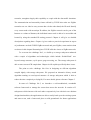
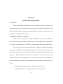
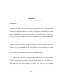
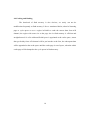
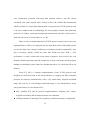
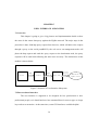
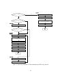
Below is a brief introduction to the whole system – “sensor data management
infrastructure based on the hardware environment of 801.15.4/ZigBee sensor network”.
A system diagram below depicts how the system is constructed.
5
RF communication
Subsystem(Client)
IEEE 802.15.4/
ZigBee Network
Query Subsystem
Storage Subsystem
Collecting
Subsystem
RF
communication
Subsystem(Man
age Node)
User
Interface
Subsytem
Hardware of sensor
node
Figure 1 System Architecture
The sensor network hardware consists of a couple of development board with
CPU ChipCon2430, a system-on-chip radio frequency chipset supporting 2.4G Hz
IEEE 802.15.4/ZigBee application. An 8k byte RAM and 128K bytes Flash memory
are build-in into the chipset, as well as a high-performance radio transceiver. A
temperature sensor is also included inside the chipset[11,12,13]. Based on hardware
supports, a software system is developed in an attempt to collect the data sampled by
sensor, store them to the permanent memory space, remotely look up the specific data
we need from the storage of remote nodes with high efficiency by using the highperformance search algorithm and radio frequency communication, provide friendly
query interface to the non-professional users, support the TCP/IP protocol stack [19,
6
21] on top of IEEE 802.15.4 MAC and physical layer[2, 3]. This software system is
comprehensive solution which empowers users to file a search request from a browser
in users’ PC, and the query result will be returned and displayed by the browser. The
data storage subsystem takes care on both aspects of efficiency and data reliability by
using the RAM as the first level cache and Flash Memory as the permanent storage
space, under the cache-to-flash synchronization algorithm, the data will be save with
efficiency and consistency. The cyclic queue data structure enhances the storage
subsystem with higher data utility ratio in limited Flash memory spaces, it also place a
solid foundation under the data query subsystem which is implemented by using the
cyclic binary search algorithm. The support of 802.15.4/ZigBee makes it easier and
convenient to interchange data and interact with other ZigBee network. The TCP/IP
feature on this system makes the connection-oriented reliable packet transportation and
flow control possible. Based on it, plenty of network applications like http web server,
DHCP, FTP, SNMP are applicable with no difficulties.
1.1 Outline
Chapter 2 gives an overview regarding to the hardware environment including
the features of the chip set ChipCon 2430 and his development board.
Chapter 3 describes the sensor data collecting subsystem which will enable the
sensor board to sample and capture the analog data from sensor and use some
mechanisms to notice the application.
7
Chapter 4 depicts how sensor data storage subsystem works, some important
components and implementation approaches are illustrated such as the cycle queue and
cache buffer.
Chapter 5 presents the algorithms and data structures that sensor data query
subsystem uses, and the implementation details to guarantee it to be a rapid solution
compared to other solutions.
Chapter 6 explains the approaches that are leveraged by radio frequency
communication subsystem. Some detailed introductions regarding IEEE 802.15.4 and
ZigBee will be found in this chapter, the features and usages of software library of PHY
and MAC layer is discussed as well as the TCP/IP implementation on top of ZigBee
protocol stack.
Chapter 7 discusses the user interface subsystem in terms of how it is built and
the major technologies and software modules involved
Chapter 8 provides a research report on real time operating system for
embedded system. The typical RTOS system called RTX51 tiny is introduced in
comprehensive aspects 0066rom task scheduling, timer tick to stack management. Also,
some processing logics within the kernel of RTX51 tiny are also analyzed.
Chapter 9 give us an practical experiment on how TCP/IP protocol stack
improves the ZigBee Network’s capabilities on handling heavy data traffic situations.
8
CHAPTER 2
HARDWARE ENVIRONMENT
2.1 Overview
There development environment in terms of hardware mainly consists of two
components: The chipset module plug-in board and the development main board. Some
tightly related parameters regarding to the functionalities of these two components will
be introduced in the following sections.
2.2 Hardware Summary on Chip Set
There are three versions in the family of Chipcon 2430, they are CC2430-F32,
F64 and F128, the number behind ‘F’ means the size of the flash memory. The one that
we use in the development is CC2430-F128, which includes 128 K bytes flash memory.
The CC2430 is a true System-on-Chip (SoC) solution specifically designed the
requirement of IEEE 802.15.4 and ZigBee applications. The CC2430 is equipped with
an industry-standard enhanced 8051 MCU, 8K bytes RAM and 128K bytes flash
memory. A high performance radio frequency transceiver is also built in the chip.
Featured with various operating modes, CC2430 is suited for systems where ultra low
power consumption is required. Some important hardware features are listed below [11,
12, 13]:
・ High performance and low power 8051 microcontroller core.
・ 2.4 GHz IEEE 802.15.4 compliant RF transceiver in radio core.
9
・ 128 KB in-system programmable flash
・ 8 KB on-chip RAM, 4 KB with data retention in all power modes
・ CSMA/CA hardware support.
・ Digital RSSI / LQI support
・ Battery monitor and temperature sensor.
・ 8-14 bits ADC with up to eight inputs
・ AES security coprocessor
・ Two powerful USARTs with support for several serial protocols.
・ One IEEE 802.15.4 MAC Timer, one general 16-bit timer and two 8-bit
timers
・ 21 general I/O pins, two with 20mA sink/source capability
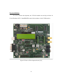
2.3 Hardware summary of development board
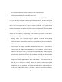
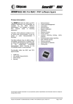
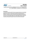
SmartRF04EB is the name of the development board. SmartRF04EB is the
platform for development and testing on both hardware and software. Some important
features are worth to be mentioned [28]:
User interface
The SmartRF04EB includes an LCD panel, two pushbuttons, one joystick and 2
LEDs to help developers get the intuitive feedback from hardware during the
development. A potentiometer is built in for analog measurement, the board is also
featured with an audio filter and amplifier enabling transmission and reception of audio
signals.
10
In Circuit Emulator:
For more efficient development, the CC2430 includes an on-chip real time In
Circuit Emulator (ICE). SmartRF04EB controls the emulator via the USB interface.
Figure 2 Picture of Development board [28]
11
CHAPTER 3
SENSOR DATA COLLECTING SUBSYSTEM
3.1 Overview
Sensor data collecting subsystem enable the sensor board to sample and capture
the analog data from sensors, and convert the analog data to digital value which will be
delivered up to application. Firstly the hardware background is given, then we present
the implementation regarding to control sensors, A/D channels, and deliver data to the
application level.
3.2 Relevant Hardware
CC2430 has a built-in analog temperature sensor, the measurement parameter is
0.763V at 0°C and 2.44mV / °C. [12]. The A/D conversion channel is provided to
sample the temperature, convert the sampled data to digital data and output data to the
certain pin port of the chipset, and then the application is able to access the pin port and
get the value.
On the other hand, there is also a potmeter at the Evaluation Board, when the
potmeter is turns on, the voltage will be sampled, converted by controlling the A/D
channels.
3.3 Software Implementation
In order to enable the A/D channel, the SFR( Special Function Register )
ADCCFG is required to be initialized correctly, then the next step is to select the ADC
12
conversion sequence by set the corresponding bits in register ADCCON. To start the
sampling, certain bit has to be set in ADCCON, if the hardware level sample has been
done, certain bit in ADCCON will be set to indicate this issue, and the data after A/D
conversion will be put into register ADCH which is addressable for application [12].
In the common cases, people would like to get the sensor node doing sampling
periodically instead of doing it manually or single time. The best way to put the
sampling and A/D conversion to run in a fixed interval is using interrupt. There are
there timers in CC2430 for us to use, after users set the timer correctly and run, when
the time-out event occurs, an interrupt event will be triggered, then the interrupt routine
corresponding to the timer will be called by the kernel. Users can customize specific
operations that will be performed into the interrupt routine, and update the system
interrupt vector by changing the value of timer routine entry to customized function
address.
13
CHAPTER 4
SENSOR DATA STORAGE SUBSYSTEM
4.1 Overview
This chapter describes how our system store the data collected by collecting
subsystem. This subsystem is capable to store large amount of logs of sensor data. We
build up this subsystem enhanced with a couple of algorithms and technologies which
include “RAM+Flash” two-layered storage structure, cyclic queue, page-accessing, etc.
The storage subsystem is able to store at most 47K sample data. Considering the RAM
and flash memory offer distinct virtues on store data as well as their distinct flaws,
firstly, we briefly discuss about what can RAM and flash memory can do and not do,
secondly, a two layer structure “caching and flashing” structure is presented on how to
combine the merits of both RAM and flash memory to make the data to be stored
reliably and efficiently. The third, in the flash memory part, the cycle queue data
structure will be discussed as well as the page accessing mechanism.
4.2 RAM and Flash memory
Data storage subsystem is used to save the data that sensors have sampled into
CC2430’s memory space as sort of log data for the later usage. There are 8K bytes of
RAM and 128K bytes Flash memory in CC2430, RAM owns the fast accessing
operation but it is sort of vulnerable storage, only maintains data when the power is on,
on the other hand, flash memory has slow accessing speed but possess the functionality
14
for reliable storage even without the power supply. Most of modern computer
architectures make use of the merits of both of them to pursue the balance the accessing
performance and the reliability by applying a two-layer structure: use RAM as the cache
to store the most recent and most dynamic data, and use flash memory to store the less
recently or used data. In our system, the similar approach is adopted to increase the
software response speed and provide the permanent storage at the same time.
4.3 Page Accessing and Cycle Queue
In addition, in CC2430, the write operation is different to the read operation.
The smallest accessing unit in reading flash memory in our system is byte, but the
counterpart in writing flash memory is block with size of 2k bytes. So the best way for
us to manage the flash memory is block accessing [12, 29].
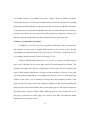
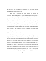
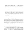
With the limited flash memory size, we create a cycle queue in Flash memory
space as the container for the sensor data, which is being generated periodically. The
operating unit to the cycle queue is a page/block of size 2k bytes, this is accordant to the
traits of flash memory that the size of single writing operation is 2k bytes. Every page
will be assigned an page ID in an ascending order from 0 to N-1( N is the total page
number of the queue ). In an attempt to indicate the current starting location of the
queue (head of the queue), the Head_PageID is maintain for this purpose meaning the
head page ID, it also means that the data stored in this page are the least recent data in
the whole queue. Another variable called UsedPageCount is used to monitor the size of
the queue, it tells the how many pages were used to store data. The following figure
illustrate how cyclic queue works:
15
RearPage
MedianPage
HeadPage
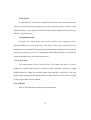
Figure 3 Cyclic Queue
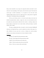
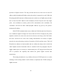
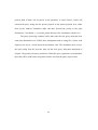
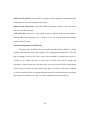
When the cache page in RAM is full, the content of whole page will be dump
into the cycle queue, here two scenarios will occur, one is the cycle queue is not full, the
other is the cycle queue is full right before the dumping processing.
In the first case, the system will locate the right page position to save the page
from cache, it should be the rear of the cycle queue, the location will be figured out by
adding
two
parameters:
the
size
of
the
queue
and
the
head
pageID
( HeadPageID+PageUsedCount ), one situation has to be concerned with is that when
the HeadPage is behind the rear page, the sum of this two parameters is not right due to
the fact that the part beyond the end of queue has to be wrapped back to the start of the
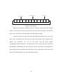
queue. The following figure gives us an intuitional image:
16
HeadPage
HeadPage
UsedPageCount = 11
UsedPageCount = 9
UsedPageCount = 10
HeadPage
Figure 4 Insertion operation of cyclic queue
In the second case, full queue is never unlikely in the queue operations,
generally speaking, two measures we can take: deny the insertion, or overwrite the head
of queue. Since we have ceaseless sensor data coming along time passing, it is
unreasonable to deny the new data and keep the old data in the queue. So overwriting
the head page is our choice. The process of this is to locate the rear page ID firstly, and
move one page further so as to get the head page, overwrite this page and change the
HeadPageID to point to next page of original head page, and the size of
queue( PageUsedCount ) keep unchanged.
17
4.4 Caching and flashing
The drawback of flash memory is also obvious, we surely can not do
modification frequently to flash memory. Like we mentioned before, ahead of inserting
page to cycle queue we use a region in RAM to cache the newest data from A/D
channel, the region with same size to the page size in flash memory is efficient and
straightforward. So a fix-addressed RAM space is appointed as the cache space, sensor
data got freshly from A/D channel will be put into the cache first, the subsequent data
will be appended to the cache space until the cache page is out of space, when the whole
cache page will be dumped to the cycle queue in flash memory.
18
CHAPTER 5
SENSOR DATA QUERY SUB-SYSTEM
5.1 Overview
As we mentioned in the previous chapter, the storage subsystem is capable to
store large number of sensor data into the flash memory. It raises a challenge that how
to locate a specified data in the middle of the sensor data efficiently. We propose an
alternative binary search algorithm running on two-layered structure of storage
subsystem which is able to reduce the time complexity to O(log2N)
Firstly, we will give a comparison of several candidate query algorithms.
Secondly, we make our choice and explain the reasons that we choose binary search.
Thirdly, the dynamic binary search and static binary search, two derived from binary
search are applied to our system and make our solution fast and satisfy the searching
requirements in both cache area and cycle queue.
5.2 Comparison of searching algorithms
Quite a few mature and widely-used search algorithms are there in the software
industry to cope with this question. Linear Search, Binary Search, Hash Table Search, B
or B+ tree, Skip List, etc are the most well-known techniques in the search areas. None
of them are perfect for all cases, they have their merits and drawbacks[22, 23, 24, 25].
19
Linear search is easiest one to be implemented, but with no efficient
performance, when the data set is large, the performance is unacceptable due to low
CPU benchmark and lack of memory on embedded system.
Hash table search technically is the fastest algorithm, but it has to take much
more concerns and energies onto solving the conflict problem along with more and
more items were added into the hash table [24], one other drawback of hash table search
is it is not capable to do the range search quickly.( search data that falls into the
specified range ).
[22] gives us a detailed illustration on B or B+ tree, which is suitable to handle
the case in which huge numbers of data were contained, but the balancing operation is a
extremely tedious, and will turn into be overloaded workload at some extent. Plus, the
memory allocation mechanism is required as prerequisite if B tree is consider to be used.
In some embedded system operating system, this mechanism is not provided due to the
simplicity sake.
Skip list owns a good balance between performance and simplicity [26], it uses
multi-linked list to accelerate the search, the search process will go through those multilinked list from top layer to the bottom, but stick to the one direction, making the
searching happens like jumping among several link list to get to the desired destination
finally. Skip list has to generate a random number to decide the layer number for the
new-added item which at the same time disables it to guarantee time complexity in
terms of search operation, in the worst cases, the search operation will be identical to
20
the linear search. One more thing is the same to B+ tree, the memory allocation
mechanism is also a base requirement [25].
Binary Search is significantly fast search algorithm with O(log2N) time
complexity. The key of data stored by binary search algorithm is required to be in
order( ascending or descending order ). No matter using static memory allocation or
dynamic memory allocation, binary search will work well and show the same search
performance. So far due to the dynamic memory allocation mechanism is temporarily
not available in our operating system running on our sensor node, plus the maturity that
binary search owns, and code complexity which will affect the footprint of our
executable program( the smaller the better ). We figure binary search is the best choice
so far according to what we have on the aspect of hardware environment and the
software development kits.
5.3 Dynamic and static binary search
Like the last chapter mentioned, the flash memory accessing mechanism
designed by CC2430 is not identical in the aspects of reading and writing. Block writing
has to be applied when writing request happened. But reading operation is performed in
same way with doing regular external memory reading which is byte-level. Since search
operation is a kind of read-only operation, we can search and examine to the level of
item in the cycle queue. At the same time, in the scenario where the specified data
locates into the cache instead of in the cycle queue, binary search is also feasible to be
applied to the RAM space, only difference between them is that, in cache page, the
search range is fix( from the beginning of the page to the end of page ), we call it static
21
binary search; meanwhile, in cycle queue, the range that contains stored data is various
from time to time depending on the frequency of the insertion requests. That means the
search range is movable continuously, we are required to revise the static search
algorithm slightly and put some more control logic into it, and generate an upgraded
version that we call dynamic binary search algorithm.
The key part of binary search is to select the search window, then locate the
median item right inside the window, compare the value to be search and the value of
the median item, then determine which half of the window we should go further, that
half of window will turn into be new search window, similar processing are repeated
until the value is found.
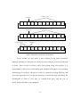
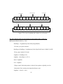
The range containing data in the cycle queue is various, the pointer HeadPageID
and queue size( PageUsedCount ) are used to monitor the variance of this range. Let’s
make definition for some terms here in order to illustrate the search procedure
intuitively, later an figure also depicts how to locate and split the window:
Definitions:
HeadPage: First page ID of the queue that stores data.
RearPage: The last page ID of the queue that stores data.
OrgHead: The first item that stores the oldest data.
OrgRear :The last item that stores the most recent data.
Distance: The size (in items) of the search window.
22
MedianPage
RearPage
MedianPage
HeadPage
RearPage
HeadPage
Figure 5 Two cases in splitting the window in cyclic queue
The ADT (abstract data type) description for the dynamic binary search tree:
Def DynamicBinSearch( key, *val ) :
HeadPage = LogSummaryCache.Head_PageNumber;
//For the cycle queue structure
RearPage=(HeadPage+ LogSummaryCache.PageUsedCount-1)%MAX_PAGE;
//Every page contain 512 items.
OrgHead = HeadPage*512;
OrgRear = (RearPage+1)*512-1;
head = OrgHead;
rear = OrgRear;
//Flag to mark if the head pointer is ahead of rear pointer originally, used to
//determine if the search processing should stop or not.
OrgState = ( head >= rear );
23
//Size of the window
distance = ( rear-head ) in case of ( head<rear );
OR
( (512*MAX_PAGE)-(head-rear) ) in case of (head >= rear );
// The median location of window
dobber = (head + distance/2)%(MAX_PAGE*512);
// Process to shrink the window.
For( ; (head==rear) or (head>=rear) == OrgState ; )
{
if ( time > [item at dobber].time )
{
head = dobber+1;
}else if ( time < [item at dobber].time )
{
rear = dobber-1;
}else
{ // Found the specified key.
*val = PageLog[dobber].val_1;
return TRUE;
}
//Adjust the size of window.
Distance = ( rear-head ) in case of ( head<= rear )
24
OR
( (512*MAX_PAGE)-(head-rear) ) in case of ( head > rear )
// Caculate the new median location in new window.
Dobber = (head + distance/2)%(MAX_PAGE*512);
}
At last, with all this preparation works being ready, the API( Application
Programming Interfac ) is given for the developer to search the specified key inside
sensor data storage system.
BOOL LocateLog( INT16 time, UINT8 * val );
Where,
Time is the key to search, val is the pointer of memory specified by invoker to
store the result data;
Return value: TRUE if key is found, FALSE otherwise.
25
CHAPTER 6
RADIO FREQUENCY COMMUNICATION SUBSYSTEM
6.1 Overview
ZigBee network lacks of data traffic-intended consideration, since its major
designing purpose doesn’t lie on this. ZigBee protocol is not ideal to carry the large
amount of payload. In an attempt to compensate this gap, we build a TCP/IP stack on
top of ZigBee stacks, strengthen largely their capability to couple with the data traffic
situations. The retransmission and reassembly features offered by TCP/IP also make our
ZigBee networks now are suitable to carry stream data. On the other hand, the IP stack
enables the ZigBee network can be part of the Internet, the sensor node is able to be
accessible and located by using the standard IP routing protocol.
This chapter mainly depicts the how our system accomplishes radio frequency
communication based on 802.15.4/ZigBee standard. Some detailed introductions
regarding IEEE 802.15.4 and ZigBee protocol stack will be found in this chapter, the
features and usages of software library of PHY and MAC layer is discussed, lastly, the a
light-weighted but richly featured TCP/IP implementation specific to our system on top
of ZigBee protocol stack is gone through.
6.2 Overview of IEEE 802.15.4 and ZIGBEE
ZigBee is a PAN (Personal Area Network) wireless networking solution that
supports low data rates, low power consumption, and security, promoted by ZigBee
Alliance. ZigBee is based on the IEEE 802.15.4 specification which was ratified in May
26
2003. ZigBee is designed specifically to replace the proliferation of individual remote
controls and sensor devices[5, 6], A home-area network covers an areas of 30-70
meters, consists of one or more kinds of electronic devices including sensors, actuators,
appliances and asset-tracking device, security surveillance equipments and so on.
ZigBee is a protocol stack to standardize the behaviors on the wireless communication
within these diversified devices. If we do some survey into the HAN network, we will
notice that the wireless payloads circulating within the network, sent and received by
most of the devices are small packets, they carry the control commands, the running
status that need to be monitored. For some widely-used applications, for example the
smoke detector installed in every kitchen, at most of the time, the detector is in deepsleep mode, only generate a burst of alarm information in case of the trigger event
( heavy smoke detected ) happening. So some characteristics are necessary for the
device in HAN networks:
* Allow long sleeping time;
* Very low power consumption;
In the previous couple of years, WLAN( Wireless Local Area Network )
technologies were invented, gain the explosive progress and own their space in the
industry quickly, such as Wi-Fi and Bluetooth. Both of them and ZigBee have the
function to communicate remote devices wirelessly, but each of them has the specific
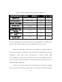
functionalities and performance benchmarks, Table-1 shows the traits comparison
within Wi-Fi, Bluetooth and ZigBee.
27
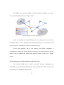
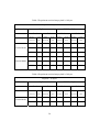
Table-1 Comparison within Wi-Fi, Bluetooth and ZigBee [9]
ZigBee
Application
Monitoring and control
System resources
4KB – 32KB
Battery life (days)
more than 1000
“unlimited” in theory, 32000
in reality
20 to 250
Network size
Bandwidth(KB/s)
Bluetooth
Cable
replacement
more than
250KB
1 to 7
Wi-Fi
Web, Email,
Video
more than
1MB
1 to 5
7
32
728
54000
Transmission range
(meters)
30-70
10
100
Power consumption(TX
mode)
25 to 35 mA
40 mA
more than
400 mA
Power consumption
3 µA
200 µA
20 mA
Standby mode
The main advantages of ZigBee compared to Bluetooth and Wi-Fi are the very
low power consumption in sleeping mode and the small footprint of the ZigBee stack
protocol, which make it possible to provide components with very low cost.
What’s the relationship of IEEE 802.15.4 and ZigBee? We might consider the
802.15.4 as physical radio and ZigBee as the logical network and application software.
According to OSI( Open system Interconnection ) reference model, IEEE
802.15.4/ZigBee covers three layers, the lowest two layers: physical(PHY) and media
access layer( MAC ) belong to IEEE 802.15.4 standard, the layer above these two, are
defined by ZigBee standard [8].
In 802.15.4, four basic frame types are defined: Data, ACK, MAC command,
Beacon. Data Frames supports a payload with size of 104 bytes with unique frame ID
28
for tracking purposes. ACK frame acknowledges the packet has been received by the
destination node correctly. MAC command frame are used to control and configure the
client node by coordinator. Beacon frame is like notice message for the client nodes,
client nodes are wake up by the beacon frame. They listen on the PAN network, and
will go back to the sleep mode if no beacon frame is received.
ZigBee devices can be divided by three kinds of categories:
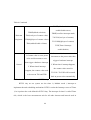
Table-2 Categories of ZigBee devices [8]
Device type
Characteristics
Role in the network
Coordinator
Maintain the overall network information,
requires the most memory and computing
power
Pan network manager
Full function
device(FFD)
Full support 802.15.4
Coordinator or
network router
Reduced
function
Limited functionality
Network-edge device
device(RFD)
ZigBee networks are designed to conserve the power of the slave nodes. For
most of the time, a slave device is in sleeping mode and wakes up only for a fraction of
a second to let the coordinator know its presence in the network.
ZigBee network can run under Beacon or non-beacon strategies. Basically, in
non-beacon mode, each client is autonomous, acting like two-way radio network, can
establish a conversation at will, but the conversation perhaps will be disturbed by others
occasionally. The beacon mode is able to control the power consumption in whole
network and extended network. In this mode, the two-way network is managed by
29
central dispatcher in terms of controlling the channels and manager the calls, by which
it optimized the power consumption of whole network.
Non-beacon mode is typically deployed as security systems where ZigBee end
devices, like intrusion sensors, sleep most of the time. They wake up on a regular
interval( might be long time period ) to announce their presence in the network. When
an event shows up, the sensor is triggered and wakes up immediately and sent the alert
( “Somebody’s entered the front gate”). The network coordinator listens to the network
all the time and can therefore wait to hear from each of these end devices. Due to fact
that network coordinator has enough power supply it can allow clients to sleep for
unlimited periods of time, non-beacon mode enables the slave nodes to save power.
On the contrary, beacon mode is fitter to be used if the network coordinator has
limited power supply. The side to listen is end devices, they listen for the network
coordinator’s beacon (broadcast at certain interval). An end device registers with the
coordinator and looks for any messages to itself. If no messages are pending, the client
returns to sleep, awaking on a schedule specified by the coordinator to listen to beacon
coming next. Once the end device communications are completed, the coordinator itself
returns to sleep for the sake to lower power consumption.
The NWK layer is in charge to associate or dissociate devices through the
network coordinator, routes frames to their destination and perform security. In addition,
the NWK layer of the network coordinator also in charge of starting a new network and
assigning an address to newly associated devices.
30
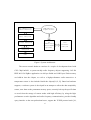
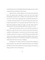
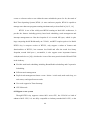
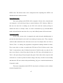
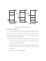
The NWK layer specifies multiple network topologies including star, cluster
tree, and mesh, which are shown in Figure below.
Figure 6 ZigBee network model [8]
In the star topology, one of the FFD-type devices will play the role of network
coordinator and is used for initiating and maintaining the devices on the network. All
other end devices, communicate with the coordinator directly.
In the mesh topology, like in star topology, the ZigBee coordinator is
responsible for starting the network and for choosing key network parameters, but the
network can be expanded and interact with network outside via the use of ZigBee
routers.
6.3 Specification in CC2430 and Physics and MAC Layer
The CC2430 IEEE 802.15.4 MAC and PHY software implements the
functionality as specified by the IEEE 802.15.4 specifications. The MAC software may
run by using a CC2430EB development kit.
31
Functionality of the MAC and PHY layers include following features as described in
[30]:
z CSMA-CA
z Link quality measurements.
z Data Transfer
z Retransmission
z Fame acknowledgement
z Association/Disassociation
z Beacon notification.
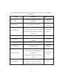
The software of MAC and PHY layer has plenty of interfaces for developers to
control and manage the diversified elements in ZigBee network. The most frequently
used API is shown below in Table – 3:
32
Table-3 Important APIs in PHY& MAC layer libraries in Chipcon CC2430 ZigBee
solution
API
MAC_INIT
mpmSetRequest
Features
Where to apply
Setup MAC framework and DB
Coordinator or
peripherals
devices
Power up MAC sublayer
Coordinator or
devices
Set the PIB attributes.
mlmeSetRequest
(The MAC PIB contains the attributes
Coordinator or
required to manage the MAC sublayer
Devices
of a device).
mlmeStartRequest
mlmeScanRequest
mlmeAssociateRequest
mcpsDataRequest
Start service of the coordinator
Scan the network for existing
coordinator
Associate with the specified coordinator
Send out the data
Coordinator
Devices
Devices
Coordinator or
Device
Call back function called by the MAC
layer when a packet transmission
mcpsDataConfirm
initiated by
mcpsDataRequest() has succeeded or
Coordinator /
Device
failed.
is used to request pending data
mlmePollRequest
(transmitted using indirect data
transmission) from the coordinator
33
Device
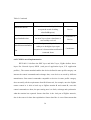
Table-3 Continued
mlmePollConfirm
Call back function called by MAC layer
to report the result of calling
Device
mlmePollRequest()
Call back function that is invoked by
mcpsDataIndication
the MAC layer when a data frame is
successfully received
mlmeDisassociateIndica
tion
Coordinator or
Device
Callback generated by the MAC
sublayer to the higher layer upon
reception of a disassociation notification
Coordinator
command frame
6.4 TCP/IP Protocol Implementation
IEEE 802.15.4 defines the PHY layer and MAC layer, ZigBee defines above
layers like Network layers( NWK ) and part of application layer( E.X. application
profiles ), The current standard enables the devices defined in same profile category can
interact the control commands and exchange data, even devices are made by different
manufactures. But control commands compatible to devices in same profile category
does not satisfy all the requirements from HAN network, for example, once the ZigBee
remote control A is able to hook up to ZigBee monitor B and control B, once this
control commands are done, the part coming next is to fetch, exchange and synchronize
what the monitor has captured. Sensor data flow is the vital part of ZigBee network,
also is the source for later data exploitation. Sensor data flow is sort of data stream that
34
were continuously generated with large data payload, which is not like control
commands with small payload body. Facing to these, the reliable data transmission
which is suitable for stream data transportation is in great needs. TCP/IP protocol stack
is de facto standard and overwhelmingly the most popular network interconnecting
protocol, it is reliable, connection-oriented data transmission with flow control, make it
ideal to be the carrier of stream data [18, 19, 20].
There are lots of implementations for TCP/IP protocol stacks, but it is not every
implementation is ideal to be deployed onto an embedded system. Embedded systems
are not like large scale computer architecture and mature personal computer(PC), they
lack of memory( Mostly, RAM less than 10K, ROM less than 256K ), CPU
performance is much weaker than main stream computers, these lead to the code
footprint, RAM requirement and code complexity are three vital factors for the program
running on embedded systems. Based on consideration above, we choose the uIP as our
solution.
From [17], uIP is a compact implementation of the TCP/IP protocol stack
designed for small 8-bit and 16-bit microcontrollers. It supports the RFC-compliant
protocols for network communication, with a very small binary footprint and RAM
usage, uIP code size is a few kilobytes and RAM usage is a few hundred bytes. Some
extra good features of it are shown below:
z RFC standard TCP and IP protocol implementations, including flow control,
fragment reassembly and retransmission time-out estimation.
z Unlimited number of listening TCP connections, maximum amount is configurable.
35
z Free for both commercial and non-commercial use or modification.
z Well documented and well commented source code.
uIP’s source code also includes the low level driver under TCP/IP, in the most
of version, the driver included is the most typical Ethernet driver. Our hardware system
does not have Ethernet network card and related interface, the driver come with uIP
source code is not required at all, we have to replace it with the driver suitable to our
hardware environment. According to the OSI reference model, our TCP/IP stack should
be built on top of ZigBee protocol, the Chipcon Corporation does not have any software
solution for that temporally, so providing such a solution by ourselves is our choice.
The development mainly focuses on:
1. Making such a driver based on ZigBee’s protocol stack, this driver should
implement the data transmission by using the programming interface provided by
PHY and MAC layers.
2. Some features are tightly coupled to Ethernet network, such as ARP, will be
removed since the ZigBee network hardware is not feasible to broadcast the IP
address to the network and try to get the corresponding MAC address. ZigBee
network has the at least one FFD to be the coordinator, when the end device start the
connection and try to associate to the network, the coordinator will catch the request,
assigned the unused ZigBee address( IEEE 64bit format or 16bit short format ) to
that end device, initialize the channel, allocate the network resources, specify the
parameter of the new connection, and finally send address back to the end device,
on the other hand, ZigBee routers do not have to associate to certain coordinator,
36
and other devices that communicate with it are the ZigBee routers too, their
addresses are static and pre-configurated during planning and constructing the
ZigBee network. Above two scenarios prove that ARP is not necessary in ZigBee
network according to the current IEEE specification.
3. An alternative DHCP mechanism is necessary to provided on coordinators, since the
PHY & MAC address of ZigBee network is IEEE 64bit format or 16 bit short
format, TCP/IP use IP address to locate the machine, we need to have some
translation operations from IP address to ZigBee address when a packet is being
sent out. Since ARP protocol is not ideal for ZigBee network, we consider the new
protocol like below:
When an end devices file the request to associate to the coordinator, the
coordinator in charge of not only assigning the ZigBee address for the end device, but
also assigning the IP address for it, and record down the matching relationship of this
ZigBee-IP addresses pair into its address translation table. When the client( end device )
send a packet to coordinator, the IP layer will extract the destination IP address inside
the IP header, and look it up within the translation table, if item is found, the value that
pairs with the IP address will be the ZigBee address that points out the where the packet
should finally reach. By confirmed with the ZigBee destination address, the PHY and
MAC layer will do their duty to deliver the packet right to the end device.
One issue that we should pay attention to is: The ATT( address translation table )
is mostly only necessary onto the coordinator, in most of the cases, end devices don’t
require ATT, this is decided by the center-coordinator-management mechanism
37
specified on ZigBee network. The only part that end devices need is the its source IP
address and the destination IP address where the packet is supposed to reach. Unlike the
IP routing and ARP structure in Ethernet network, end devices in ZigBee network don’t
have to know the MAC address of the destination, because they have the only single
point – the coordinator to contact, packet will be transmitted to the coordinator, the
coordinator will look the MAC address(ZigBee address) up given by the packet’s
destination IP address.
If the TCP/IP communication occurs within one PAN( Personal Area Network ),
one coordinator might be enough, but if more than one PAN are deployed, the packet
might be needed to be sent to the some devices that are not belong to the PAN where
the source end device lies. Here some routing functionalities are needed, in ZigBee
network, the network topology consists of a number of PANs and the routers. The PAN
ID and device address are both needed when we address the unique device inside the
whole ZigBee network. Remember what we mention in the last paragraph, Only IPZigBee address pair are recorded, we should modify the ATT and put PAN ID into the
ATT to guarantee the capability that enables the global ZigBee network data
transmission.
The routing mechanism is very similar to the one in TCP/IP protocol, so we take
advantage of the routing module in uIP software to implement the TCP/IP routing on
ZigBee network.
38
CHAPTER 7
USER INTERFACE SUBSYSTEM
7.1 Overview
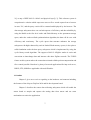
This chapter is going to give a big pictures and implementation details on how
the users do the sensor data query against the ZigBee network. The major steps in the
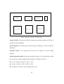
procedure is that: Send http query request from browser, which will deliver the request
through a proxy to the serial port(RS232), the web server on management node will
phase the http request and send the query request to the destination node, the query
response will be send back following the same route reversely. The architecture of this
module is shown below:
HTTP
Browser
Local Network
Private
Protocol
HTTP
SerProxy
RS232
Manage Node
ZigBee
IEEE 802.15.4/
ZigBee Network
Figure 7 Structure of User Interface Subsystem
7.2 Browser-based interface
The user interface is supposed to be designed for less professional or nonprofessional people, so it should not have lots command lines for users to type or a large
keyword set to memorize. At the same time, some GUI interfaces would be helpful.
39
We choose use the Internet browser to be the most frontal interface to face the
users. Its compliancy to the RFC Internet standard: HTTP, HTML, XML, DHTML etc,
make the Internet communication is much more convenient than other GUI interfaces,
furthermore, it is probably the software that people can the most easily get for free.
Every modern operating system comes with browser.
7.3 Way to hookup
The browsers are used onto users’ desktop or laptop, a way that let the PC hook
up to ZigBee network has to be figured out, otherwise the communication can not be
accomplished. There are a couple of channels available to be used to interact with the
outside devices, such as Serial port( RS232 ), USB, Radio Frequency. We choose the
serial port communication as our approach to hook the PC up to the sensor network in
the current version of system. This kind of mature technology is widely-accepted by the
industry, and convenient for developer to build the communication work up.
The next step of work is how to get the browsers send their data through the
serial port. Generally speaking, browsers work based on the TCP/IP network
environment, such as Ethernet and Wi-Fi, they send data up to the network that PC
attached instead of the serial port. In this situation, a proxy is an ideal software to make
our requirement come true. We use a proxy software called “SerProxy”( can be
downloaded in [10] ), it has the features to transmit data transparently between TCP/IP
and serial port. Once SerProxy is startup, it listens on specified TCP port, once some
data come in, it is able to redirect the data transparently to the serial port. With the help
of SerProxy, we configure a proxy setting of browser to the machine where SerProxy is
40
running on, the port the SerProxy is listening, The browser will send the http request to
the SerProxy, which will redirect what it receives to the serial port. When all these are
ready, a web server is supposed to be running on to the sensor node to accept these http
requests from the serial port interface connected by SerProxy.
7.4 Processing within ZigBee network
A web server is very import in our system, currently it is running onto the sensor
node with specified functionality. It is called manager node, it acts like a bridge to
connect serials port to the query subsystem and RF communication subsystem. It
includes the following components:
1. HTTP parser
HTTP parser is featured to parse the http request coming from serial port, it
analysis the http request header, get the exact query command from the header, and it
also need to parser the address information from the http request to make clear onto
which node the request is expecting to look up. After that, the parser will invoke the
“query starter” to transfer the query out and wait for the query result to come. Once the
response of the query is coming back, it will create the response message in standard
HTTP format and send it back to the SerProxy via the serial port, SerProxy will transfer
intact response back to the browser, then, the query result will be shown up into
browser.
2. Query starter.
Query starter is called by web server when the HTTP parser’s job is done, at this
moment, the query string is extracted, the address information( IP address ) is also
41
present, both of them will be passed as the parameter to Query Starter, which will
reformat the query string into the private protocol as the packet payload, next, either
look up the Address Translation table and then forward the packet to the right
destination ( Coordinator ) , or post the packet directly to the coordinator( end device ).
The query processing continues on the other side after the query string has been
send to the destination over TCP/IP, here management node is acting like a client, send
request to the server, which means the destination node. The destination node receive
the query string from the network, then call the local query subsystem mentioned at
Chapter 5 by passing the query parameters. When the query operation is accomplished,
the result will be send back tracing back from the way that the query request came.
42
CHAPTER 8
RESEARCH OF EMBEDDED OPERATING SYSTEM
8.1 Overview
Chipcon2430 is quite new hardware compared with the other 8051 chipset in the
current market, plus the fact that Chipcon Corp. doesn’t provide customers its own
RTOS solution, which lead to the fact that there is no corresponding operating system
solution on this chipset for education purpose. We migrate the RTX51 tiny (RTOS) to
our sensor nodes successfully, even though there is no existing example that we could
reference.
Embed OS specially the real time operating system is major attention in this
chapter. Some basic concepts are introduced firstly, followed by the fact that we choose
RTX51 tiny as our RTOS, thirdly we migrate RTX51 tiny to our system (ChipCon2430),
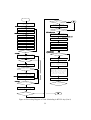
and the distinctions on implementation details between 8051 standard CPU and
Chipcon2430 followed, finally, we analysis and illustrate technologies used at some
vital parts of RTX51 tiny including the stack management, task scheduling and
initialization procedure.
8.2 Overview of Embedded Operating System
Along with the more and more powerful hardware equipped to the embedded
system, more and more hardware features are provided, it also means the corresponding
software running on embedded system proliferate rapidly. The architecture of single
task assisted with interrupt mechanism become incapable to handle all these hardware
43
events or software tasks to run within the same embedded system. So far, the trend of
Real Time Operating System( RTOS ) is more and more popular, RTOS is capable to
manage more than one programs running simultaneously as described in [14, 15, 16].
RTX51 is one of the widely-used RTOS running on Intel 8051 architecture, it
provide the features including priority based task scheduling, stack management and
interrupt management etc. But the footprint of it is around 6K bytes, which is quite
large comparing the 8K RAM totally on CC2430, and RTX requires quite a few RAM.
RTX51 tiny is compact version of RTX51, only support a subset of features and
functionalities of RTX51, but consume less RAM and offer the much less binary
footprint( around 900 bytes ), meanwhile, it also support some important features
well(shown below as [14]), which make it one of the most practical and efficient RTOS
in the industry:
z Flexible multi-task scheduling including Round-Robin scheduling and Cooperative
Scheduling.
z Efficient stack management
z Explicit task management feature: create / delete / switch task, make task sleep, set
task status, send signal between tasks.
z User code support in Timer Interrupt.
z CPU Idle mode.
8.3 Migrate to our system
Though RTX51 tiny supports various 8051 series CPU, but CC2430 is a kind of
enhanced 8051 CPU, it is not fully compatible to industry-standard 8051 CPU, so the
44
source code( Assembly language ) of RTX51 tiny does not take effect due to the
incompatibility. In the attempt to deploy RTX51 tiny to CC2430 hardware, we have to
port a new version that is adapted to CC2430 by revising some parts of code within the
incompatible module. One of the most vital modules that are not compatible is the timer
click module.
RTX51 Tiny leverages the standard 8051 Timer to generate a periodic interrupt
which is called RTX51 Tiny Timer Tick. Other Timeout and interval values specified
for the RTX51 Tiny are based on timer tick, which means they are all measured by
using the Timer Tick.
Standard 8051 CPUs function some built in registers to provide the timer tick, there
are one to four timer available in 8051 CPU depending on the model of hardware, in the
most common scenario, the first timer will be used to generate the timer click. RTX51
tiny uses the standard 8051 Timer 0 (mode 1) to generate the timer tick, but in CC2430,
the counterpart is Timer 1( Modulo Mode ). The differences between them are listed
below:
Table-4 Difference between 8051 and CC2430 in controlling time tick timer
Standard 8051
CC2430
Name of
Timer0
Timer 1
Timer
Mode
Mode 0
Modulo Mode
45
Table-4 Continued
T1CTL(Mode selection and
enable/disable timer)
TMOD(Mode selection)
TIMIF(overflow interrupt mask)
Relevant
TL0(low byte of counter value)
Registers
TH0(high byte of counter value)
T1CC0L(low byte of counter)
T1CC0H(high byte of counter)
TR0(enable/disable of timer)
T1IE(Timer1 interrupt
enable/disable)
1. Counter value is set to zero and
1. Counter value is set to preset
increments to the preset value then
value and decrements to zero
trigger a hardware interrupt.
then trigger a hardware interrupt.
Control
2. When timer1 interrupt happens,
2. When timer0 interrupt
the counter value stored in
happens, the counter value need
T1CC0L/ T1CC0H will be turned
to be reset to TL0 and TH0
back to preset value automatically
8.4 Basic software architecture of RTX51 tiny
RTX51 tiny on our system use the timer 1( Modulo mode ) interrupt to
implement the task scheduling mechanism. RTX51 rewrite the Interrupt vector of Timer
1, let it point to the code defined in RTX51 tiny. The interrupt of timer1 is called Timer
tick, which is the base measurement unit for all other timeout and interval used in
46
RTX51 after. The timeout value can be configured at the compiling time. RTX51 can
schedule the tasks with two modes:
Round Robin mode
Each task running on the RTOS will be assigned a fix time slice, when the task
was assigned, it will own the privilege to control hardware, CPU, Memory, DMA etc.
But once the time slice is running out, the CPU will switch the control privilege to
another task that is in “Ready” status. As what is mentioned in [15], in Round Robin
mode, each task has the same time slice, every task in Ready status will be run in turn.
Cooperative mode
In this mode, no time slice is assigned to the tasks, the task scheduling logic is
put into the tasks themselves, the task is not running in turn any more. They cooperate
with each other and decide who will be the next to run. For example, There are Task A,
Task B, Task C is running, the programmer designed the running schedule for them,
First A runs, after A is done, A transfers the CPU time to Task C( B has to wait ), then
Task C is start and run, when C finishes his job, he let Task B to take over, then it’s B’s
turn to run, likewise, when B has done his duty, the CPU time will be handed over to
Task A, this processing will repeat again and again, if these three tasks cooperate with
each other in a certain way that all of them comply with, they are able to run smoothly
and share the CPU time with no delay and blocking, [16] gives a similar introduction on
Cooperative mode.
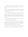
The major components inside RTX51 tiny kernel are illustrate as the software
structure diagram below:
47
Global
information
block
Table of Stack
Pointers
System Registers
System STACK
Table of Task
Timer/State
Pointers
Task_
delay
_bit
Program counter
Register( PC )
Figure 8 Software structure in RTX51 tiny
System STACK: Stored into the IDATA segment, the maximum address of STACK is
defined by macro RAMTOP.
System Registers: all running state related registers including ACC, PSW, B, R0-R7,
DPH, DPL,
Program Counter: Core register that stored the code address of current running
program.
Global Information Block: Stored into the Bank1 registers. It’s a global buffer to hold
the crucial and frequently updated task information. The Block consists of
z saveacc: temporary buffer for ACC, 1 byte;
z savepsw: temporary buffer for PSW, 1 byte;
z currenttask: Task ID of current running task, 1 byte.
48
Table of stack pointers: Lies in IDATA segment, a table storing the stack pointers(SP)
with respect to each task running on the system.
Table of Task Timer/State: Allocated in IDATA segment, a table to store each task’s
left time slick and task state.
Task delay bit: a bit to be a flag which is used to indicate if the task switching is
running after timer interrupt occur, if this bit is set, the new-coming timer interrupt
routine will be ignored.
8.5 Stack Management in RTX51 tiny
The Stack space in RTX51 tiny is located in internal memory( IDATA ), all the
running tasks share the stack space together. The management mechanism is: The task
that is running( owns the CPU time ) has as much amount of available stack space as
possible to use. When this task is switch out, its stack space will be shrunk and
relocated, in other words, the used stack space used by this task will be relocated and
the unused space will be merged into the stack space used by new task that is switched
in. So the switched-in task is expanded that guarantee the current task has the maximum
stack spaces as possible to use, there is a brief explanation represented in [31].
49
RAMTOP
RAMTOP
Stack Area for
Task 2
RAMTOP
Stack Area for
Task 2
Unused Space
Stack Area for
Task 1
Step two
Step one
Unused Space by
Task 0
SP
Stack Area for
Task 2
Unused Space by
Task 0
SP
Stack Area for
Task 1
Stack Area for
Task 1
SP
Used space by
Task 0
Stack_Start
Used space by
Task 0
Used space by
Task 0
Stack_Start
Task 0 is running
Stack_Start
Task 2 is running
Figure 9 Stack Management in RTX51 tiny
8.6 Initialization of RTX51 tiny
After the embedded system is booted up, the initialization module of RTX51
will be called by the boot loader and do initialization works to prepare the data
structures and get some vital peripheral ready. A list of sequential steps will be
accomplished during the initialization procedure:
1. Initialize the table of Stack Pointer, the stack pointer table is at the location
starting from the next byte of SP register( SP+1 ). Each item in stack pointer
table will be filled with RAMTOP( 255 )
2. Initialize the table of task timer/state, The first item in table will be set non-zero
value indicating the first task is at active and ready states. The other items are
filled with zero.
3. Push the code address of first task into stack.
50
4. Configure the Timer1 with modulo mode, enable the timer1 interrupt and start
the timer.
5. Enable the global interrupt and call RET, after that, the program counter will
fetch the first two byte in stack, so enable the CPU to go to the code space to run
the first task.
8.7 Processing Diagram of Task Scheduling in RTX51 Tiny
51
Start
Is TS_DELAY bit set ?
Set Interrupt vector for T1
(JMP TIMERINT)
YES
RET
NO
Decrement ?RTX_ROBINTIME
?RTX_STACKERROR:
Stack Error Handling
NO
?RTX_ROBINTIME==0 ?
HW_TIMER: RETI
?RTX_TaskSwitching:
YES
TIMERINT:
PUSH ACC,PSW,B,DPH,DPL,AR0-AR7 into
Stack
Call HW_TIMER
Deal with current task
Get current status of current running
task
Save PSW to ?RTX_SAVEPSW
NO
PSW = 0x01( select Bank one )
CLR EA
Save ACC to saveacc
Set its K_Robin bit, and save back
Reset the timer0 counter
SETB EA
Stack space enough?
TIMERLOOP:
OS_Switch_Task:
OS_Switch_task1:
YES
TIMESHARING==0 ?
From the top of the task state table,
decrements the timer count for every
task.
NO
SET TS_DELAY bit
NO
YES
Timer Counter == 0
Scan Status Table from current task
item, try to find one with K_Ready
bit is set, otherwise keep cycling
CLR EA
The task currently waiting for
Timeout event?
YES
Adjust Stack content, and the stack
pointer table, after that, the SP
register pointers to the position
that is for the next ready
task( switch to another task )
YES
Set Ready & TMO_EVENT bits, save new
status back to STAT TABLE.
NO
NO
NoWaitTimeout:
SETB EA
?RTX_RobinTime = #TIMESHARING
NoTimeout:
Go check next task, hit last
item in table?
Next task’s K_ROBIN bit is
set ?
NO
Restore ACC from saveacc,
Restore PSW from SavePSW
TIMESHARING==0?
YES
RET
Figure 10 Processing Diagram of Task Scheduling in RTX51 tiny (Part I)
52
RobinON:
Next task’s K_ROBIN bit is
set ?
YES
NO
SETB EA
Task is waiting for signal and
receive a signal later ?
SignalOff:
SignalOn:
NoEvent:
Save new state to State Table
POP AR7-AR0, DPL, DPH, B, PSW, ACC
from the system STACK
NO
R7 = 0
Clear ?RTX_TS_DELAY flag
Task is waiting for timeout
event and timeout occurs
later ?
RET
YES
NO
Clear K_Ready, K_TMO and K_SIG bits
XCH A, @R0
Save to Status Table
SETB EA
Clear all bits but Keep K_READAY bit
ORL AR7, A
YES
Clear ?RTX_TS_DELAY flag
RET
TimeoutON:
R7 = TMO_EVENT
Clear K_SIG, K_TMO, TMO_EVENT bits
Figure 11 Processing Diagram of Task Scheduling in RTX51 tiny (Part II)
53
CHAPTER 9
PERFORMANCE TEST ON NETWORK COMMUNICATIONS
9.1 Overview
This chapter will take a performance test on performance and reliability of
network communications. Two participants involved inside this test are ZigBee network
and combination of TCP/IP and ZigBee network. The test result will tell us the
improvement that TCP/IP gives to our network when it is built onto ZigBee network.
9.2 Test Environment and terms
Two participants that were tested are Pure ZigBee networks and TCP/IP+ZigBee
networks. Some prerequisite terms are explained below:
Network Hardware
Network hardware includes two Chipcon 2430 development board with CC2430
chipset built in.
Status of Network Communication
It means how well the communications can be performance. Two network status
will be considered: Good and Bad network status, Good network means two sensor
board are close without any physical obstacles between them. Bad network means two
sensor nodes are far apart ( 20 meters ) with a couple of physical obstacles ( 6-7 walls,
and metal box )
54
Test Payload
It represents how many bytes of application data that every transmitted packet
will carry. Data payload used during the test can be divided into three scenarios: light,
middle and heavy, where light payload means 10 bytes data, middle one means 30 bytes
and heavy means 60 bytes.
Transmission model
It means how sensor nodes send out the packets? Two categories will be
considered which are packet mode and stream mode. Packet mode stands for the next
packet has to be sent after having got the acknowledgement of last packet. Stream mode
represent the packet are sent in a asynchronous mode without having to wait until the
acknowledgement of previous-sent packet arrives.
9.3 Test Procedure
Two sensor nodes will be involved, one is the sender, the other is receiver.
Sender will transmit 10000 packets with three possible payloads respectively ( light,
middle and heavy ) under two network status( Good and bad ) respectively. The time
used to finish the transmission and the number of packet that were received successfully
by the receiver node will be recorded.
9.4 Test Result
Here are the tables that record the experiment result:
55
Table-5 Experiment result when payload is 10 bytes
Payload = 10 bytes
Network
Network Status
Packet Mode
Stream Mode
ZigBee
Good
TCP/IP + ZigBee
Bad
Good
Bad
Packet
Finish
Packet
Finish
Packet
Finish
Packet
Finish
Received
Time
Received
Time
Received
Time
Received
Time
10000
40
10000
44
10000
40
9748
Null
9994
Null
9989
Null
9994
Null
9993
Null
10000
157
10000
160
10000
39
8429
Null
10000
156
10000
159
9994
Null
9994
Null
10000
157
10000
161
Table-6 Experiment result when payload is 30 bytes
Payload = 30 bytes
Network
Network Status
ZigBee
Good
TCP/IP + ZigBee
Bad
Good
Bad
Packet
Finish
Packet
Finish
Packet
Finish
Packet
Finish
Received
Time
Received
Time
Received
Time
Received
Time
10000
53
10000
56
10000
52
9748
Null
Packet Mode
56
Table 6 Continued
Stream Mode
9996
Null
9989
Null
9995
Null
9961
Null
10000
167
10000
170
9996
Null
9947
Null
10000
168
10000
171
10000
51
9999
Null
10000
167
10000
171
Table-7 Experiment result when payload is 60 bytes
Payload = 60 bytes
Network
Network Status
Packet Mode
Stream Mode
ZigBee
Good
TCP/IP + ZigBee
Bad
Good
Bad
Packet
Finish
Packet
Finish
Packet
Finish
Packet
Finish
Received
Time
Received
Time
Received
Time
Received
Time
10000
68
9532
Null
9998
Null
8689
Null
10000
68
9978
Null
9998
Null
9912
Null
10000
181
10000
184
9998
Null
9891
Null
10000
184
10000
186
10000
62
9697
Null
10000
182
10000
184
9.5 Experiment Analysis
Some statistics histograms give us the summary of the table above.
57
Recv
Packet(%)
100
100
99.995
99.99
99.99
99.98
99.985
99.97
99.98
99.96
99.975
99.95
99.97
TCP&ZigBee
ZigBee
99.94
Packet Mode in Good Network
Recv
Packet(%)
100
99
98
97
96
95
94
93
92
91
90
Payload=10
Payload=30
Payload=60
TCP&ZigBee
ZigBee
Stream Mode in Good Network
100
99
98
97
Payload=10
96
Payload=30
95
Payload=60
94
93
TCP&ZigBee
ZigBee
92
Packet Mode in Bad Network
TCP&ZigBee
ZigBee
Stream Mode in Bad Network
Figure 12 Reliability comparisons in four scenarios
These four histogram illustrate that:
58
1.
The ZigBee networks work well when the traffic is light and the network status
is healthy. But along with the traffic in the network increase, a number of
packets lost during the transmission;
2.
The number of packets that are received successfully dramatically decreases
when the statuses of ZigBee networks are week. This and the above phenomena
prove that the ZigBee networks lack of traffic-intended consideration and is not
capable of dealing with the large amount of data transmission and weak signal
situations
3.
TCP/IP+ZigBee network in our system work very well in all kinds of situations,
no matter in heavy traffic situations or in weak signal situations, no packet is
lost and the reliability of RF communication is guaranteed.
4.
Packet model provide higher percentage of receiving packets than stream mode
does when the packets are transmitted in ZigBee network.
An integrated comparison is given below in a more intuitional point of view.
59
100
99.5
99
98.5
98
97.5
97
96.5
96
95.5
95
94.5
94
TCP&ZigBee
b
30 + G
b+ oo
60 G d
b+ oo
d
10 Go
b+ od
30 B
b+ ad
60 B
b+ ad
Ba
d
ZigBee@Pack
et Mode
ZigBee@Stre
am
10
Percentage
Communication Reliability
Figure 13 Reliability comparisons between TCP/IP+ZigBee network and ZigBee
network
60
CHAPTER 10
CONCLUSION AND FUTURE WORK
ZigBee is promising protocol stack designed specially to unify the diversified
electronic device running within a PAN network, IEEE802.15.4/ZigBee has been
steadily accepted by the industry as a de facto industry standard, more and more
manufactories produce the ZigBee compatible devices. It offers people a large
momentum to develop from hardware to software product compliant to the ZigBee.
Under this background, in this thesis, a software solution for distributed sensor
data management based on IEEE 802.15.4/ZigBee network has been proposed. It
guarantees the reliable data transmissions and enables people to manage the data
generated by distributed sensor nodes efficiently. It takes advantage of the features
offered by hardware( CC2430 CPU and development board ), accomplishes the
functionalities from collecting and storing sensor data, providing efficient search
approach to locate sensor data rapidly, communicating with other node of ZigBee
network in standard TCP/IP protocol, offering users a browser based management
interface to connect their personal computer to ZigBee network and initiate the query
request. And experimental solution regarding to Real Time Operating System is also
provided in the software system.
As ongoing effort, new sensor is about to be installed onto the sensor board, and
some peripheral interface like flash memory card are also under consideration, so the
software should be improved by enriching the driver library to satisfy the requirement
61
of hardware; Compiler is tightly related with our development, specially when RTOS is
applied, every compiler has its advantage and limitation, more study need to be put on
how to provide a efficient and integrated development solution by choosing the
appropriate Compiler or related software to compile the RTOS and application code, or
doing some immigration work on RTOS and application code.
So far the management node is required to deliver the query request to the
destination node, in the future, a better infrastructure will be removing the management
node and let each node is able to be hooked up by the personal PC.
A more comprehensive web server is needed since there will be more
requirement such as file downloading, Security Socket Layer( SSL ), etc.
A File system will be able to enhance current storage mechanism to a more
flexible and manageable level.
62
REFERENCES
[1]
Ed Callaway, P. Gorday, L. Hester, J.A. Gutierrez, M. Neave, B. Heile, V. Bahl,
"Home networking with IEEE 802.15.4: A developing standard for low-rate
wireless personal area networks," IEEE Communication Magazine, August 2002.
[2]
IEEE 802.15 WPAN, Task Group 4 (TG4),
http://www.ieee802.org/15/pub/TG4.html
[3]
IEEE 802.15 on Wikipedia, http://en.wikipedia.org/wiki/IEEE_802.15
[4]
Homepage of ZigBee? Alliance, http://www.zigbee.org/
[5]
William C. Craig Program Manager Wireless Communications, ZMD America,
Inc., "Zigbee: "Wireless Control That Simply Works"", White Paper.
[6]
P. Kinney, "ZigBee Technology: Wireless Control that Simply Works," Kinney
Consulting LLC, Whitepaper 2/10/2003.
[7]
Baker,N., "ZigBee and Bluetooth strengths and weaknesses for industrial
applications" in Computing & Control Engineering Journal, April-May 2005
[8]
Mikhail Galeev, "Home networking with Zigbee",
http://www.embedded.com/showArticle.jhtml?articleID=18902431
[9]
"Bluetooth, Wi-Fi or ... ZIGBEE?"
http://www.embeddedtouch.com/et/client/041129846391.php?lg=en
[10]
Introduction of SerProxy.
http://www.lspace.nildram.co.uk/freeware.html
[11]
Chipcon: CC2430 Product Information; A true ZigBee low-cost, low-power
System-on-chip (SoC) solution
http://www.chipcon.com/index.cfm?kat_id=2&subkat_id=12&dok_id=245
[12]
Chipcon data sheet.
63
http://www.chipcon.com/files/CC2430_Data_Sheet_rev1p03.pdf
[13]
CC2430 features:
http://www.chipcon.com/index.cfm?kat_id=2&subkat_id=12&dok_id=240
[14]
RTX51 tiny Introduction. http://www.keil.com/c51/rtx51tiny/
[15]
Round Robin Mechanism in RTX51 tiny:
http://www.keil.com/support/man/docs/tr51/tr51_rrobin.htm
[16]
Cooperative task scheduling in RTX51 tiny:
http://www.keil.com/support/man/docs/tr51/tr51_coop.htm
[17]
The uIP Embedded TCP/IP Stack.
http://www.sics.se/~adam/uip/
[18]
TCP Tutorial:
http://www.ssfnet.org/Exchange/tcp/tcpTutorialNotes.html
[19]
Transmission Control Protocol(TCP),RFC 793:
http://rfc.net/rfc793.html
[20]
A TCP/IP Tutorial,RFC 1180, http://rfc.net/rfc1180.html
[21]
Internet Protocol" RFC 791, http://rfc.net/rfc791.html
[22]
Ramez Elmasri and Sham Navathe,"Fundamentals of Database Systems (4th
edition)", published by Addison Wesley, July,2003
[23]
Dennis Chester Smolarski, "The Essentials of Data Structures I", published by
Research & Education Assoc., Mar, 1990
[24]
James Andrew Storer,"An Introduction to Data Structures and Algorithms",
published by Springer, Jan, 2002
[25]
Mikhail J. (EDT) Atallah, "Algorithms and Theory of Computation
Handbook" ,published by CRC Press, Oct, 1999
64
[26]
William Pugh, "Skip Lists:A Probabilistic Alternative to Balanced Trees",
Communication of ACM, June 1990
[27]
RTX51 tiny Introduction. http://www.keil.com/c51/rtx51/
[28]
CC2430DK Development Kit. ChipCon Products From TI, White paper
http://www.chipcon.com/files/CC2430DK%20Development%20kit%20descripti
on_rev_A.pdf
[29]
HAL_CUL_EB Software User Manual.
http://www.chipcon.com/files/HAL_CUL_EB_Software_%20User_Manual_1_
1.pdf
[30]
"CC2430 IEEE 802.15.4 MAC / PHY software layers", Technical Paper of
Chipcon Corp. Confidential.
[31]
Stack Management in RTX51 tiny.
http://www.keil.com/support/man/docs/tr51/tr51_stackmgmt.htm
65
BIOGRAPHICAL INFORMATION
Tianqiang Li received his Bachelor of Science degree from Jinan University,
China P.R., 1998. After his graduation he worked as a software engineer in Suntek
Technologies until 2000, from 2000 to 2004, he worked as a software engineer in
AsiaInfo Technologies. He joined University of Texas at Arlington as a Master’s
student in Computer Science and Engineering department in Fall 2004. In Spring 2006,
and Summer 2006, he worked as a software engineer (internship) in Sipera(Dallas,TX)
and Google(Mountain View, CA) respectively. His current research interests include
embedded development, Sensor network, TCP/IP Stack, Distributed computing etc. He
received M.S. in Computer Science and Engineering from UTA in 2006.
66