1
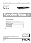
Fujitsu Semiconductor Design(Chengdu) Co.,Ltd. User Manual Inductor Heater (Half Bridge) Demo Board User Manual Inductor Heater (Half Bridge) User Manual V1.0 Chapter 错误!使用“开始”选项卡将 Heading 1 应用于要在此处显示的文字。 错误!使用“开始”选项卡将 Heading 1 应用于要在此处显示的文字。 Revision History Date 2010-03-12 2010-08-5 2010-10-11 2010-11-17 Author Kevin. Lin Kevin. Lin Kevin. Lin Kevin. Lin Change of Records V1.1.0, First draft V1.1.0, add figures V1.1.1, modify the Figure 6.2 V1.2.0, update the power level, Figure 6.2. add error code This manual contains 26 pages. 1. The products described in this manual and the specifications thereof may be changed without prior notice. To obtain up-to-date information and/or specifications, contact your Fujitsu sales representative or Fujitsu authorized dealer. 2. Fujitsu will not be liable for infringement of copyright, industrial property right, or other rights of a third party caused by the use of information or drawings described in this manual. 3. The contents of this manual may not be transferred or copied without the express permission of Fujitsu. 4. The products contained in this manual are not intended for use with equipment which requires extremely high reliability such as aerospace equipments, undersea repeaters, nuclear control systems or medical equipments for life support. 5. Some of the products described in this manual may be strategic materials (or special technology) as defined by the Foreign Exchange and Foreign Trade Control Law. In such cases, the products or portions thereof must not be exported without permission as defined under the law. © 2008 Fujitsu Microelectronics (Shanghai) Co., Ltd. MCU-AN- 500077-E-10 – Page 2 Inductor Heater (Half Bridge) User Manual V1.0 Chapter 错误!使用“开始”选项卡将 Heading 1 应用于要在此处显示的文字。 Contents Contents REVISION HISTORY ................................................................................................. 2 1 PREFACE .............................................................................................................. 5 1.1 About This Book ...................................................................................................... 5 1.2 Reference Material .................................................................................................. 5 2 INTRODUCTION OF THE DEMO BOARD............................................................ 6 2.1 Introduction ............................................................................................................. 6 2.2 Feature.................................................................................................................... 6 2.3 Demo Board Module ............................................................................................... 6 3 SYSTEM LEVEL ARCHITECTURE OF THE BOARD .......................................... 8 3.1 Board Block Diagram .............................................................................................. 8 3.2 Control Module ........................................................................................................ 9 3.3 3.4 3.2.1 MCU Socket .............................................................................................. 9 3.2.2 Key and Display ......................................................................................... 9 3.2.3 Fan and Buzzer ....................................................................................... 10 3.2.4 Temperature Measure Circuit .................................................................. 11 3.2.5 Debugger Interface .................................................................................. 11 Power Supply ........................................................................................................ 12 3.3.1 SMPS ...................................................................................................... 12 3.3.2 Filter and Rectifier.................................................................................... 12 Resonant Circuit .................................................................................................... 13 3.4.1 IGBT driver .............................................................................................. 13 3.4.2 Resonant Tank ........................................................................................ 13 4 HOW TO OPERATE THE DEMO BOARD .......................................................... 14 4.1 Assemble the Platform .......................................................................................... 14 4.2 Operate the Demo Board ...................................................................................... 15 4.2.1 Power ON/OFF ........................................................................................ 15 4.2.2 Constant Power Mode ............................................................................. 16 4.2.3 Constant Temperature Mode ................................................................... 17 4.2.4 Timing Mode ............................................................................................ 18 5 DEBUGGING AND PROGRAMMING ................................................................. 19 5.1 Debugging Tool Connection ................................................................................. 19 5.2 Overview of Project ............................................................................................... 20 6 SCHEMATIC ........................................................................................................ 21 MCU-AN- 500077-E-10 – Page 3 Inductor Heater (Half Bridge) User Manual V1.0 Chapter 错误!使用“开始”选项卡将 Heading 1 应用于要在此处显示的文字。 错误!使用“开始”选项卡将 Heading 1 应用于要在此处显示的文字。 7 ADDITIONAL INFORMATION ............................................................................. 23 8 APPENDIX........................................................................................................... 24 8.1 List of Figures........................................................................................................ 24 8.2 List of Tables ......................................................................................................... 24 8.3 MCU Pin Assignment ............................................................................................ 25 8.4 ErrorCode.............................................................................................................. 26 MCU-AN- 500077-E-10 – Page 4 Inductor Heater (Half Bridge) User Manual V1.0 Chapter 错误!使用“开始”选项卡将 Heading 1 应用于要在此处显示的文字。 Contents 1 Preface 1.1 About This Book This book provides a detailed hardware description of the half bridge inductor heater board. The demo board is a reference platform for half bridge inductor heater design. This Inductor Heater (Half Bridge) Demo Board User Manual is written for software, hardware, and system engineers, who are developing their own inductor heater project. Table1.1 shows the summary of chapters included in this manual. Chapter Title Description Preface Introduction of the Demo Board System Level Architecture of the Board How to Operate the Demo Board Debugging and Programming Schematic and BOM This chapter introduces the content of this book This chapter introduces the information of the demo This chapter explains the HW design of the demo board This chapter describes how to operate the demo board by front board This chapter introduces how to connect the demo board to the adapter. This chapter shows the schematic and BOM of the demo Table 1. 1 Chapter Summary 1.2 Reference Material Use this book in conjunction with: Inductor Heater (Half Bridge) FW User Manual v1.1.0 MCU-AN- 500077-E-10 – Page 5 Inductor Heater (Half Bridge) User Manual V1.0 Chapter 错误!使用“开始”选项卡将 Heading 1 应用于要在此处显示的文字。 错误!使用“开始”选项卡将 Heading 1 应用于要在此处显示的文字。 2 Introduction of the Demo Board 2.1 Introduction The Inductor Heater (Half Bridge) Demo Board is a reference design for customer. It contains two part, namely main board and front board. They are controlled by only one MCU. The main board is built around Fujitsu MB95F430 serial MCU. The abundant modules and peripherals make it very suitable for Inductor Heater design no matter a half bridge style or a quasi resonant one. The front board adopts LED display and capacitive touch buttons. It supports max 8 single LEDs, a LED module and 8 buttons. 2.2 Feature This demo board supports these features below. Support 8 single LEDs and a LED module (8segments) max. Support 8 touch sense buttons Afford debugging interface for MCU and tuning interface for touch sense chip 9 power levels:600w,700w,900w,1200w,1400w,1800w,2000w,2400w,3000w. Three modes: constant power, constant temperature, timing. 2.3 Demo Board Module Figure 2.1 shows the front view of the main board and the modules. Figure 2.1 main board MCU-AN- 500077-E-10 – Page 6 Inductor Heater (Half Bridge) User Manual V1.0 Chapter 错误!使用“开始”选项卡将 Heading 1 应用于要在此处显示的文字。 Contents Figure 2.2 shows the front view of the front board and the modules . Figure 2.2 Front Board MCU-AN- 500077-E-10 – Page 7 Inductor Heater (Half Bridge) User Manual V1.0 Chapter 错误!使用“开始”选项卡将 Heading 1 应用于要在此处显示的文字。 错误!使用“开始”选项卡将 Heading 1 应用于要在此处显示的文字。 3 System Level Architecture of the Board 3.1 Board Block Diagram Figure 3.1 gives a system level architecture of the demo board. It has these sections: control, power supply, resonant circuit. Figure 3. 1 Board Block Diagram MCU-AN- 500077-E-10 – Page 8 Inductor Heater (Half Bridge) User Manual V1.0 Chapter 错误!使用“开始”选项卡将 Heading 1 应用于要在此处显示的文字。 Contents 3.2 Control Module The Control Module is based on the MB95F430H. It has several specialized hardware peripherals, like 16-bit output compare unit, 10-bit ADCs, internal voltage comparator, OPAMP and buzzer driver, which are required for inductor heater control. 3.2.1 MCU Socket The demo board uses a LQFP32 footprint for MB95F430. Additionally ,there is test pins for each pin of MCU. 3.2.2 Key and Display There are 8 single LEDs (D1-D8) and a LED module on the front board. The LEDs indicate the mode that the inductor heater is being in. The LED module displays the output power Level in constant power mode, temperature in constant temperature mode or time in timing mode. All the keys are capacitive touch sense buttons. This function is implemented through AT5088 which is an ASIP for capacitive touch application. The AT5088 can support 8 buttons max. Figure 3.2 shows the key and display definition Constant temperature ON/OFF Constant Timing power + - Hour Figure 3. 2 Key Definition MCU-AN- 500077-E-10 – Page 9 Minute Inductor Heater (Half Bridge) User Manual V1.0 Chapter 错误!使用“开始”选项卡将 Heading 1 应用于要在此处显示的文字。 错误!使用“开始”选项卡将 Heading 1 应用于要在此处显示的文字。 The front board is connected with the main board through the 10-pin port including 5 wires for LED COMs, 2 wires for I2C bus and 2 wires for GND and +5V. The socket J2 on the front board is prepared for AT5088 tuning. Figure 3.3 shows the connector. Pin 1 Figure 3.3 Connector to Front Board The table below shows the pin definition of front board connector. Table 3.1 Connector Definition Pin Number Name 1 2 3~7 8 9 10 +5v GND COM0~COM4(LED) SDA SCL NC 3.2.3 Fan and Buzzer When the inductor heater works, the fan need to work at the same time to chill the heat-sink, and decrease the temperature of the rectifier module and IGBTs in advance. The fan is a 12v driving set. A 7812 is used to convert the 15v to 12v. The buzzer module is located on the main board, and it is drove by the specialized BUZ pin of the MCU. MCU-AN- 500077-E-10 – Page 10 Inductor Heater (Half Bridge) User Manual V1.0 Chapter 错误!使用“开始”选项卡将 Heading 1 应用于要在此处显示的文字。 Contents 3.2.4 Temperature Measure Circuit In order to avoid the IGBT failure caused by over temperature, a NTC is placed on the top of IGBT Q1 to monitor the temperature. Apart from the NTC on IGBT, there is another NTC is used to measure the temperature of the pot. It is placed in the middle of the wire plate where is close to the bottom of the pot. IGBT temperature Plate temperature measure measure Figure 3. 3 Temperature Measuring Port 3.2.5 Debugger Interface Socket J1 on the main board provides an interface for BGMA with MCU. The user can program the MCU or do debugging using the BGMA. MCU-AN- 500077-E-10 – Page 11 Inductor Heater (Half Bridge) User Manual V1.0 Chapter 错误!使用“开始”选项卡将 Heading 1 应用于要在此处显示的文字。 错误!使用“开始”选项卡将 Heading 1 应用于要在此处显示的文字。 3.3 Power Supply 3.3.1 SMPS A +15v DC block power supply (U1) serves as the main power supply to the control section of the demo board. The +15v power supply is supplied to the gate driver directly. A +12v power supply for the fan is generated using a regulator (U3). The +5v is also generated from +15V using the regulator U2. 3.3.2 Filter and Rectifier Before entering into the resonant sink, the 50HZ AC power has to be change to DCLink by the Filter and Rectifier stage. The filter part consists of some protection components, induction and capacitors, such as fuse (F1), relay (RL1), inductor (L2), and capacitor (C16, C14, and C21). Rectifier module RL1 convert AC to DC, then the DC power go through the L1 and C22 to the resonant sink. A current transformer T2 is embedded in the circuit for AC current measure. For more information please refer to the chapter “Schematic and BOM”. MCU-AN- 500077-E-10 – Page 12 Inductor Heater (Half Bridge) User Manual V1.0 Chapter 错误!使用“开始”选项卡将 Heading 1 应用于要在此处显示的文字。 Contents 3.4 Resonant Circuit 3.4.1 IGBT driver The IGBT driver circuit is built around IR2113 manufactured by IR. There are two power supplies for it. One is +15v which will supply power to the IGBT gate, and another is +5v which supply power to the logical part of the component. JMP1 is used to disable or enable the driver output. When the jumper is open , the driver output will be enabled ,or it will be disabled. JMP1 Figure 3. 4 IGBT Driver Block 3.4.2 Resonant Tank IGBT Q1 and Q2, C18, C24 and wire plate make up the main part of the resonant tank. J8 and J9 sever as the headers for wire plate connection. Current transformer T1 is added to the resonant sink serial with the wire plate. It will transform the current to the MCU for over current protection. A heat-sink is used here to disperse the heat generated by IGBTs and rectifier. MCU-AN- 500077-E-10 – Page 13 Inductor Heater (Half Bridge) User Manual V1.0 Chapter 错误!使用“开始”选项卡将 Heading 1 应用于要在此处显示的文字。 错误!使用“开始”选项卡将 Heading 1 应用于要在此处显示的文字。 4 How to Operate the Demo Board 4.1 Assemble the Platform This Demo Board Set consists of such parts: Main board Front board Wire plate Fan One 10-wire bus Figure 4.1 shows the assembled demo board platform. Figure 4. 1 Demo Platform MCU-AN- 500077-E-10 – Page 14 Inductor Heater (Half Bridge) User Manual V1.0 Chapter 错误!使用“开始”选项卡将 Heading 1 应用于要在此处显示的文字。 Contents 4.2 Operate the Demo Board 4.2.1 Power ON/OFF If the main board is connected to 220v,The MCU will run immediately, but the power stage doesn’t work. User can drive the relay to be on by touching BUTTON6, then the system run in standby mode . The led D5,D7 on the front board will light as indication of standby mode. The D1~D8 and LED module will not light on. User can also shift the relay to be off by touching the BUTTON6. All mentioned below can be done only after the system is in standby mode. Figure 4. 2 Standby Mode MCU-AN- 500077-E-10 – Page 15 Inductor Heater (Half Bridge) User Manual V1.0 Chapter 错误!使用“开始”选项卡将 Heading 1 应用于要在此处显示的文字。 错误!使用“开始”选项卡将 Heading 1 应用于要在此处显示的文字。 4.2.2 Constant Power Mode When touch the BUTTON1 after the system is in standby mode, the system enters constant power mode. D4 and D2 will be on and the led module will display the power level that indicates the output power. User can touch the BUTTON5 or BUTTON4 to select the power level. The first touch to each of the two buttons will trigger the selecting process with figure flickering. Touching BUTTON5 increases the power level, while touching BUTTON4 decreases the power level. The selection will be confirmed until 5 seconds after each touch. Figure 4.2 shows the constant power mode. Figure 4. 3 Constant Power Mode MCU-AN- 500077-E-10 – Page 16 Inductor Heater (Half Bridge) User Manual V1.0 Chapter 错误!使用“开始”选项卡将 Heading 1 应用于要在此处显示的文字。 Contents 4.2.3 Constant Temperature Mode Touch the BUTTON0 will shift the system to constant temperature mode from constant power mode or standby mode. D3, D1 will light on. The figure shown by led module means the target temperature that user set. The user can touch the BUTTON5 or BUTTON4 to change the target temperature. Figure 4.3 shows the constant temperature mode. Figure 4. 4 Constant Temperature Mode MCU-AN- 500077-E-10 – Page 17 Inductor Heater (Half Bridge) User Manual V1.0 Chapter 错误!使用“开始”选项卡将 Heading 1 应用于要在此处显示的文字。 错误!使用“开始”选项卡将 Heading 1 应用于要在此处显示的文字。 4.2.4 Timing Mode If the system is already in constant power mode or constant temperature mode, the user can touch the BUTTON7 to make system entering timing mode. The system will run in constant power mode or constant temperature mode until the time is out. After that, it will back to standby mode automatically. In timing mode, user can touch the BUTTON3 or BUTTON2 to select hour or minute setting, and touch the BUTTON5 or BUTTON4 to change the content. The figure which is in setting will flicker in frequency of 1HZ as the same as mentioned before. The rang of time is 1minute to 1hour and 59 minutes. Figure4.4 shows the timing mode. Figure 4. 5 Timing Mode with Constant Power Output Note: 1. User can quite constant power mode, constant temperature mode or timing mode by BUTTON0, BUTTON1, BUTTON7 respectively. 2. If the system is in timing mode, the touch to BUTTON0 or BUTTON1 is invalid. 3. In constant power mode or constant temperature mode, the touch to BUTTON3 or BUTTON2 has no effect. MCU-AN- 500077-E-10 – Page 18 Inductor Heater (Half Bridge) User Manual V1.0 Chapter 错误!使用“开始”选项卡将 Heading 1 应用于要在此处显示的文字。 Contents 5 Debugging and Programming 5.1 Debugging Tool Connection Figure 5.1 shows how to connect the adapter to demo board. Figure 5. 1 Adapter Connection MCU-AN- 500077-E-10 – Page 19 Inductor Heater (Half Bridge) User Manual V1.0 Chapter 错误!使用“开始”选项卡将 Heading 1 应用于要在此处显示的文字。 错误!使用“开始”选项卡将 Heading 1 应用于要在此处显示的文字。 5.2 Overview of Project The project can be opened using SOFTUNE V3.0. The files are listed in the left table. Figure 5.2 shows the project. Figure 5. 2 Project More information for the SOFTUNE V3, please refer to the SOFTUNE Workbench USER’S MANUAL. MCU-AN- 500077-E-10 – Page 20 Inductor Heater (Half Bridge) User Manual V1.0 Chapter 错误!使用“开始”选项卡将 Heading 1 应用于要在此处显示的文字。 Contents 6 Schematic Figure 6.1 shows the front board circuit. Figure 6. 1 Front Board MCU-AN- 500077-E-10 – Page 21 3 3 3 2 4 2 4 2 1 ACL 3 2 E J5 1 N J4 1 L J3 1 ACN 4 T1_3 Vo- Vo+ J17 2 1 R68 2.2K C30 104 +15V R17 470K/1W D20 HER107 HER107 R56 610R D19 +5V 1mH Vin U3 7805 Vin U2 L2 CON8 R66 1K R61 5.1K 7812 1 1 4 1 IGBT_H 1 LED COM22 LED COM33 4 IGBT_L CMP1_P 5 6 OC1 LED COM17 CMP2_P 8 R48 D17 D18 500R HER107 HER107 2 1 C29 547uF/50V 4 RV1 10K471 CON8 D22 15V DC C43 104 T1_4 AC-DC +5V ACL ACN E U1 C16 2uF/275VAC F1 10A/250V CON8 1 SYS_V 2 BUZ 3 NULL SDA/DATA4 SCL/CLK 5 6 SYS_C PLATE_T 7 IGBT_T 8 Vout 3 2 3 R50 1K C45 102 R46 100R OC1 C37 104 +12V C32 104 +5V RES_C R28 4.7K R26 4.7K IN4148 Reserved C39 47uF/25V Vout C31 4.7uF/25V 3 C14 0.001uF/400VAC D4 IN4007 R54 0R Q3 9013 47K/1W R3 Q4 8050 2 1 C47 102 R55 270R FAN 2 1 J7 R53 1K IN4148 D16 D12 500R R25 T2 1:1500 RV2 10K471 +5V R33 4.7K IN4148 C50 102 R52 100R OC BUZZER Q7 8050 2 1 2 1 +5V U5 C35 104 SYS_C 4.7uF/25V C40 R62 0R 1 4 DBG SYS_PW LED COM0 FAN VCC XA1 XA0 DC- DC+ GBJ2510 AC- AC+ RT1 C34 4.7uF/25V 3 2 C6 10uF/16V SYS_V R34 2.2K +5V R13 2.2K D1 IN4148 D21 C38 5.6V/0.5W 104 D14 IN4148 +12V IN4148 D15 +5V IN4148 R60 5.1K C26 104 D13 610R R24 RELAY SPST 3 D5 IN4007 R6 470K/1W C17 2uF/275VAC C21 0.001uF/400VAC RL 4 ACN +12V 2 1 D10 ACL CON8 SYS_PW SURGE 1 LED COM42 CMP3_P 3 4 OC 5 RST 6 X0 7 X1 8 VSS 2 4 1 XA0 2 XA1 3 VCC 4 C 5 FAN 6 LED COM0 SYS_PW7 8 DBG 1 3 J16 400uH 2.2K R58 8M Y1 MB95F434 P12/EC0/DBG/U1 P62/OPAMP_O P61/OPAMP_N P60/OPAMP_P C VCC P13/TRG0/OUT1 P14/PPG0/OUT0 BUZ 8 7 6 C41 C 4 104 5 3 2 1 U4 C28 33pF J9 104 C48 +5V R67 2.2K R51 10K T1_4 2 C5 104 D2 IN4148 R4 1K T1 1:3000 C33 33pF C24 0.68uF/1200VAC R27 0.03R/5W RES_C 470K/1W R14 2.2K R8 +5V 0.68uF/1200VAC C18 J8 4 2 4 C22 4.7uF/400VAC L1 R7 470K/1W C3 104/400V VSS J15 X1 1 3 J14 GND 2 GND 2 32 VSS 3 1 RST 29 2 4 3 10 28 1 31 PF1/X1 P01/INT01/AN01 NULL P00/INT00/AN00 9 SYS_V X0 30 11 PF0/X0 P02/INT01/AN02/UCK OC 13 PF2/RSTX P03/INT01/AN03/UO 12 CMP3_P 27 DBG J1 1 2 3 4 5 6 7 8 9 10 R5 4.7K R32 2.2K P70/CMP0_O/OUT0 P71/CMP0_P P72/CMP0_N P73/CMP1_O/OUT1 P74/CMP1_P P75/CMP1_N P76/CMP2_O/UCK P63/CMP2_P OC1 CMP1_P IGBT_L LED COM3 LED COM2 IGBT_H 22 21 20 19 18 17 Date: Size B Title LED COM1 23 SCL/CLK SDA/DATA R43 2.2K R39 4.7K/1% +5V R41 10K/1% +5V R38 5.1K/1% IGBT_T IR2113 9 10 11 12 13 14 15 16 Friday , Nov ember 19, 2010 Document Number 1/1 Sheet Induction Heater Main Board (half bridge) R20 R21 10K 10K CMP2_P R37 4.7K/1% PLATE 2 1 24 C36 104 2 1 J6 C27 22uF/50V R40 2.2K/1% PLATE_T C49 102 R22 10R/0.5W R18 10R/0.5W C23 105 +5V R23 10K R19 10K 1 C42 104 of 2 1 +5V 1 R47 1K/1% Rev V1.4.1 IGBT_L IGBT_H CON10 J2 IGBT 2 1 J10 R30 47R R45 2.2K R36 2.2K JMP1 1 2 3 4 5 6 7 8 9 10 R29 47R C19 C20 4.7uF/50V 103 +15V +5V NC2 NC3 VDD HIN SD LIN VSS NC4 R63 3.3R C51 10uF/50V IC1 8 7 HO 6 VB 5 VS 4 NC1 D9 HER107 +15V 3 NC0 2 VCC 1 COM R35 2R/0.5W LO R64 2R/0.5W D7 HER107 R9 R10 R11 R15 R16 100R 100R 100R 100R 100R +5V C2 102 C12 C13 C1 4.7uF/25V 102*5 C7 C8 C9 C10 C11 LED COM3 LED COM2 LED COM1 LED COM0 LED COM4 SDA/DATA SCL/CLK D6 HER107 DBG +5V +5V R42 8.2K/1% D11 15V/0.5W T1_3 C25 Q2 0.033uF/1200VIRGP4068D Q1 IRGP4068D D8 15V/0.5W 0.033uF/1200V C15 SURGE P67/CMP3_N 14 SYS_C P04/INT01/AN04/UI SURGE 25 P64/CMP2_N LED COM4 P66/CMP3_P P05/INT01/AN05 26 P65/CMP3_O/UO P06/INT01/AN06 15 P07/INT01/AN07 16 MCU-AN- 500077-E-10 – Page 22 PLATE_T Figure 6. 2 Main Board IGBT_T 2 12 1 J13 Inductor Heater (Half Bridge) User Manual V1.0 Chapter 错误!使用“开始”选项卡将 Heading 1 应用于要在此处显示的文字。 错误!使用“开始”选项卡将 Heading 1 应用于要在此处显示的文字。 Figure 6.2 shows the main board circuit. Inductor Heater (Half Bridge) User Manual V1.0 Chapter 错误!使用“开始”选项卡将 Heading 1 应用于要在此处显示的文字。 Contents 7 Additional Information For more information on FUJITSU MICROELECTRONICS products, please visit the following website at: Simplified Chinese Version: http://www.fujitsu.com/cn/fmc/services/mcu/mb95430/ English Version: http://www.fujitsu.com/cn/fmc/en/services/mcu/mb95430/ MCU-AN- 500077-E-10 – Page 23 Inductor Heater (Half Bridge) User Manual V1.0 Chapter 错误!使用“开始”选项卡将 Heading 1 应用于要在此处显示的文字。 错误!使用“开始”选项卡将 Heading 1 应用于要在此处显示的文字。 8 Appendix 8.1 List of Figures Figure 3. 1 Board Block Diagram ........................................................................................... 8 Figure 3. 2 Key Definition..................................................................................................... 9 Figure 3. 3 Temperature Measuring Port.............................................................................. 11 Figure 3. 4 IGBT Driver Block .............................................................................................. 13 Figure 4. 1 Demo Platform ................................................................................................... 14 Figure 4. 2 Constant Power Mode ........................................................................................ 16 Figure 4. 3 Constant Temperature Mode .......................................................................... 17 Figure 4. 4 Timing Mode with Constant Power Output ......................................................... 18 Figure 5. 1 Adapter Connection ........................................................................................... 19 Figure 5. 2 Project............................................................................................................... 20 8.2 List of Tables Table 1. 1 Chapter Summary ................................................................................................. 5 MCU-AN- 500077-E-10 – Page 24 Inductor Heater (Half Bridge) User Manual V1.0 Chapter 错误!使用“开始”选项卡将 Heading 1 应用于要在此处显示的文字。 Contents 8.3 MCU Pin Assignment Pin Number Pin Name Function 1 PG2/PPG0/X1A/OUT1 Sub clock 2 PG1/TRG0/ADTG/X0A Sub clock 3 Vcc Vcc 4 C C 5 P60/OPAM_P Fan 6 P61/OPAM_N LED COM0 7 P62/OPAM_O SYS_PW 8 P12/EC0/UI/DBG DBG 9 P00/INT00/AN00 System voltage measuring 10 P01/INT01/AN01/BZ Buzzer 11 P02/INT02/AN02/UCK NULL 12 P03/INT03/AN03/UO SDA for I2C 13 P04/INT04/AN04/UI SCL for I2C 14 P05/INT05/AN05/TO0 System current measuring 15 P06/INT06/AN06/TO1 Plate temperature measuring 16 P07/INT07/AN07/EC0 IGBT temperature measuring 17 P70/CMP0_O/OUT0 IGBT driver H 18 P71/CMP0_P LED COM2 19 P72/CMP0_N LED COM3 20 P73/CMP1_O/OUT1 IGBT driver L 21 P74/CMP1_P OC protection reference voltage 22 P75/CMP1_N OC input 23 P76/CMP2_O/UCK LED COM1 24 P63/CMP2_P Surge protection reference voltage 25 P64/CMP2_N Surge input 26 P65/CMP3_O/UO LED COM4 27 P66/CMP3_P Short circuit protection reference voltage 28 P67/CMP3_N Short circuit protection 29 PF2/RSTX Reset 30 PF0/X0 oscillator 31 PF1/X1 oscillator 32 Vss Vss MCU-AN- 500077-E-10 – Page 25 Inductor Heater (Half Bridge) User Manual V1.0 Chapter 错误!使用“开始”选项卡将 Heading 1 应用于要在此处显示的文字。 错误!使用“开始”选项卡将 Heading 1 应用于要在此处显示的文字。 8.4 ErrorCode Error Code Description Notes E0 HW_STOP is set E1 Low voltage the power supply is lower than 185V E2 Over voltage the power supply is higher than 256V E3 Pot temperature sensor is short E4 Pot temperature sensor is open E5 IGBT temperature sensor is short E6 IGBT temperature sensor is open E7 Pan over temperature the temperature of pan bottom is higher than 200 ºC E8 IGBT over temperature the temperature of IGBT is higher than 80 ºC MCU-AN- 500077-E-10 – Page 26