1
LINK/2+
Integrated Connectivity Systems
User's Guide
MC15811
June 1994
TimePlex Group
Worldwide Headquarters
400 Chestnut Ridge Road
Woodcliff Lake, NJ 07675
USA
(888) 777-0929 • (201) 391-1111
Americas Division
400 Chestnut Ridge Road
Woodcliff Lake, NJ 07675
USA
(888) 777-0929 • (201) 391-1111
CANADA
30 Fulton Way
Richmond Hill, ON
Canada L4B-1E6
(905) 886-6100
Americas Customer Support
16255 Bay Vista Drive
Clearwater, FL 34620
USA
(727) 530-9475
Timeplex Federal Systems, Inc.
Far East Division
12150 Monument Drive
Suite 750
Fairfax, VA 22033
USA
(703) 385-3366
30th Floor, Windsor House
311 Gloucester Road
Causeway Bay
Hong Kong
(852) 2830 9889
Europe/Middle East/Africa
Division
Australia/New Zealand
Division
Langley Business Centre
Station Road, Langley
Slough, Berkshire, SL3 8DT
United Kingdom
(44) 0 1753 601000
Level 21
1 York Street
Sydney, NSW 2000
Australia
(612) 9 247 1422
EUROPE/AFRICA DISTRIBUTORS
10 Rue de Genéve, Bte 17
B-1140 Brussels
Belgium
(32) 2 745.02.30
FRANCE
39 Avenue des Trois Peuples
F-78180 Montigny-le-Bretonneux
France
(33.1) 30.64.81.00
GERMANY
Edisonstrasse 11-13
D-60388 Frankfurt
Germany
(49) 610-973-8505
4/98
NO WARRANTIES ARE EXTENDED BY THIS DOCUMENT. The technical information in this document
is proprietary to Timeplex, Inc. and the recipient has a personal, non-exclusive and non-transferable
license to use this information solely with the use of Timeplex products. The only product warranties
made by Timeplex, Inc., if any, are set forth in the agreed terms and conditions for purchase of a
Timeplex product. Timeplex, Inc. disclaims liability for any and all damages that may result from
publication or use of this document and/or its contents except for infringement of third party copyright or
misappropriation of third party trade secrets. No part of this document may be reproduced in any manner
without the prior written consent of Timeplex, Inc.
U.S. GOVERNMENT RESTRICTED AND LIMITED RIGHTS
All software and related software documentation supplied by Timeplex, Inc. to the United States
Government are provided with Restricted Rights. Use, duplication, or disclosure by the Government is
subject to restrictions as set forth in subparagraph (c)(1)(ii) of the Rights in Technical Data and Computer
Software clause at DFARS 252.227-7013 or subparagraph (c)(2) of the Commercial Computer Software–
Restricted Rights at CFR 52.227-19, as applicable.
All documentation, other than software documentation which are provided with Restricted Rights, are
provided with Limited Rights. U.S. Government rights to use, duplicate, or disclose documentation, other
than software documentation, are governed by the restrictions defined in paragraph (a)(15) of the Rights
in Technical Data and Computer Software clause at DFARS 252.227-7013.
“DFARS” is the Department of Defense Supplement to the Federal Acquisition Regulation.
Contractor/manufacturer is Timeplex, Inc., 400 Chestnut Ridge Road, Woodcliff Lake, NJ 07675.
The information in this document is subject to change without notice. Revisions may be issued at such
time.
Timeplex and LINK/2+ are registered trademarks of Timeplex, Inc.
TIME/VIEW, miniLINK/2+, and microLINK/2+ are trademarks of Timeplex, Inc.
ACCUNET is a registered trademark of American Telephone and Telegraph Company.
IBM is a registered trademark of International Business Machines Corporation.
NOTICE
Telecommunications products must be installed and operated in compliance with the relevant
National Regulatory requirements summarized in the REGULATORY section of User’s Guide.
READ IN FULL, PRIOR TO INSTALLATION, any product-specific National Regulatory
requirements applicable to the country of installation.
©1987, 1988, 1989, 1990, 1991, 1992, 1993, 1994, 1997, 1998
ii
Timeplex, Inc.
L2UG
12/31/97
DISCLAIMER
Ascom Timeplex is now Timeplex, Inc. The new company logo is
. Please disregard any references to the company’s former
name in this manual.
Thank you.
1998 Timeplex, Inc.
01/01/98
WARNING
NO OPERATOR SERVICEABLE PARTS ARE INSIDE
THIS EQUIPMENT. SERVICE MUST BE PERFORMED
BY QUALIFIED SERVICE PERSONNEL.
VORSICHT
NICHT VOM BENUTZER REPARIERPARE TEILE IM
GEHÄUSE.
BITTE
WENDEN
SIE
SICH
AN
QUALIFIZIERTES WARTUNGSPERSONAL.
ATTENTION
CET APPAREIL NE CONTIENT AUCUN ELÉMENT QUE
L'UTILISATEUR PUISSE RÉPARER. CONFIER LA
MAINTENANCE À UN PERSONNEL TECHNIQUE
QUALIFIÉ.
L2UG
7/31/95
iii
MODELS COVERED BY THIS MANUAL
This manual applies to the microLINK/2+ (6-slot Mainframe), miniLINK/2+ (13-slot
Mainframe), and LINK/2+ (18-slot Mainframe) Integrated Connectivity Systems with the
following software versions:
Module
Boot PROM Number
Software Number
Network
NCL
RP48101C
Interlink
Integrated Trunk
ILC
ILQ
RP47780B
RP50013E
RP50003B, RP50004B
X.50 Server
XSM
RP48117A
RP48120A
Voice Server
VSM.3
RP48142A
RP48141A
Voice Server
VSM.5
RP48197A
RP48198A
NOTE:
RP50012J
The suffix revision letters on the boot PROM and software numbers listed in this table
may not agree with the current suffix revision letters.
NOTES: In this manual, the term LINK/2+ System is used to represent all
models unless specific reference to a particular Mainframe type is
needed.
In this manual, a module name is used generically to represent all
models of that module, e.g., Quad Asynchronous Module includes
QAM, QAM.1, QAM.2, QAM.3, and QAM.6. A model designation,
e.g., QAM.1, is generally used to refer to a specific model or
interface.
HOW TO USE THIS MANUAL
This manual is part of a three-volume set which also includes the LINK/2+ Configuration
Planning Manual and LINK/2+ Installation and Maintenance Manual. Other related publications
include:
• LINK/2+ Bipolar Framing Module (BFM) User’s Manual, MC15486
• LINK/2+ Bipolar Interface Module (BIM.8, BIM.9) User’s Manual, MC15237
The LINK/2+ System must be installed by qualified service personnel and be functioning
properly before a user can begin operation.
o
o
Program the LINK/2+ System using worksheets filled out in accordance with the LINK/2+
Configuration Planning Manual. Refer to Chapter 6, Configuration Commands, for
configuration guidelines, typical configuration procedures, and configuration command
descriptions.
Operate the LINK/2+ System using supervisory port commands described in the Commands
section of this manual:
•
iv
To monitor system status and alarms, see Chapter 5, Display Commands.
L2UG
6/30/97
•
To connect/disconnect channels, change parameters, and perform other configuration
activities, see Chapter 6, Configuration Commands. For detailed information on any
parameter, see the LINK/2+ Configuration Planning Manual. If changes to DIP switch
settings are needed, see the LINK/2+ Installation and Maintenance Manual.
•
To perform diagnostic tests, see Chapter 7, Diagnostic Commands.
Users should also familiarize themselves with the Introduction section of this manual before
operating the LINK/2+ System.
o
Isolate faults and perform corrective maintenance on the LINK/2+ System according to
information given in the LINK/2+ Installation and Maintenance Manual.
NOTE:
The Installation and Maintenance Manual is for use by qualified
service personnel only.
ORGANIZATION OF THIS MANUAL
This manual describes how to operate your LINK/2+ System. The information is organized as
follows.
Introduction (Chapters 1 and 2)
This section provides information that a user should be familiar with before using the LINK/2+
System.
• Chapter 1, Product Description, describes the key features of the LINK/2+ System,
provides a functional description of the system and its modules, and gives system
specifications.
• Chapter 2, Getting Started, presents information a user needs to start using the LINK/2+
System, such as power application and turn-off, self-test and other start-up activities, and
supervisory port log in and log out. This chapter also includes procedures for loading
operational software and database backup.
Commands (Chapters 3 through 7)
This section explains how to operate the LINK/2+ System using supervisory port commands.
• Chapter 3, General Information, explains the command format and provides operational
guidelines.
• Chapter 4, Support Commands, discusses supervisory port operational commands and
command files.
• Chapter 5, Display Commands, describes the commands that provide status, statistical, and
configuration information.
L2UG
6/30/97
v
• Chapter 6, Configuration Commands, describes the commands used to configure the
LINK/2+ System. This chapter also includes guidelines for performing configuration
activities and typical configuration procedures.
• Chapter 7, Diagnostic Commands, describes the commands that allow the user to test
channels, intermachine links, modules, and alarm relays.
Appendixes
Appendix A provides error and status messages.
SERVICE
For service in the U.S., contact Customer Support at 1-800-237-6670.
For service outside the U.S., contact your local sales representative.
Information required for service is:
Model No: ______________________
Serial No: __________________________
WARNINGS, PRECAUTIONS, AND NOTES
Be sure that you understand all directions, warnings, and limitations before using this product. In
this manual:
• WARNINGS present information or describe conditions which if not observed could result in
injury.
• PRECAUTIONS reflect conditions which could cause product damage or data loss.
• NOTES describe limitations on the use of the equipment or procedure.
IF PRODUCT IS RECEIVED DAMAGED
Forward an immediate request to the delivering carrier to perform an inspection and prepare a
damage report. SAVE container and packing material until contents are verified.
Concurrently, report the nature and extent of damage to Customer Support so that action can be
initiated to repair or replace damaged items or instructions issued for returning items.
The responsibility of the manufacturer ends with delivery to the first carrier. ALL CLAIMS for
loss, damage, or nondelivery must be made against the delivering carrier WITHIN 10 DAYS OF
RECEIPT of shipment.
vi
L2UG
6/30/97
TO RETURN PRODUCT
Please obtain instructions from Customer Support before returning any item(s). Report the fault
or deficiency along with the model, type, and serial number of the item(s) to Customer Support.
Upon receipt of this information, Customer Support will provide service instructions or a Return
Authorization Number and other shipping information. All items returned under this warranty
must be sent to the manufacturer with charges prepaid.
L2UG
6/30/97
vii
Contents
INTRODUCTION
Chapter 1. Product Description
APPLICATIONS................................................................................................................ 1-1
PRODUCT FEATURES..................................................................................................... 1-2
Node Capacity ............................................................................................................... 1-2
Advanced Bandwidth Management (ABM).................................................................... 1-3
System Security Features ............................................................................................... 1-4
Redundant Operation ..................................................................................................... 1-6
FUNCTIONAL DESCRIPTION......................................................................................... 1-7
Mainframe ..................................................................................................................... 1-7
Fan Housing .................................................................................................................. 1-7
Power Supply Chassis and Power Supply Module.......................................................... 1-9
Network Module............................................................................................................ 1-9
Driver Module ............................................................................................................. 1-10
Interlink Module .......................................................................................................... 1-10
Digital Termination Module......................................................................................... 1-10
Link Framing Module .................................................................................................. 1-10
Bipolar Interface Module ............................................................................................. 1-11
Integrated Trunk Module ............................................................................................. 1-11
D-Channel Module ...................................................................................................... 1-12
Voice Processor ........................................................................................................... 1-12
Analog Voice I/O Channel Modules ............................................................................ 1-13
Voice Server Module ................................................................................................... 1-14
Channelized Services Processor ................................................................................... 1-15
X.50 Server Module..................................................................................................... 1-15
Bypass Module ............................................................................................................ 1-15
Data I/O Channel Modules........................................................................................... 1-16
SPECIFICATIONS........................................................................................................... 1-17
Chapter 2. Getting Started
POWER APPLICATION AND TURN-OFF....................................................................... 2-1
Procedure 2-1. Power Turn-On ...................................................................................... 2-2
Procedure 2-2. Power Turn-Off...................................................................................... 2-2
SELF-TEST AND OTHER START-UP ACTIVITIES ....................................................... 2-3
Self-Test ........................................................................................................................ 2-3
Bit Error Rate (BER) Test.............................................................................................. 2-5
Channel Connections ..................................................................................................... 2-6
Alarm Indicators and Messages...................................................................................... 2-6
ACCESSING THE SUPERVISORY PORT ....................................................................... 2-7
Supervisory Port Log In................................................................................................. 2-8
Supervisory Port Log Out .............................................................................................. 2-8
viii
L2UG
6/30/97
NETWORK MODULE/INTERLINK MODULE OPERATIONAL SOFTWARE .............. 2-9
Procedure 2-3. Loading Network Module/Interlink Module
Operational Software ................................................................................................ 2-9
INTEGRATED TRUNK MODULE OPERATIONAL SOFTWARE................................ 2-11
Procedure 2-4. Loading Integrated Trunk Module Operational Software ...................... 2-12
X.50 SERVER MODULE OPERATIONAL SOFTWARE ............................................... 2-14
Procedure 2-5. Loading X.50 Server Module Operational Software.............................. 2-14
Procedure 2-6. Copying X.50 Server Module Operational Software ............................. 2-16
VSM.3/VSM.5 VOICE SERVER MODULE OPERATIONAL SOFTWARE .................. 2-16
Procedure 2-7. Loading VSM.3 or VSM.5 Voice Server Module
Operational Software .............................................................................................. 2-17
Procedure 2-8. Copying VSM.3 or VSM.5 Voice Server Module
Operational Software .............................................................................................. 2-18
SYSTEM CONFIGURATION ......................................................................................... 2-19
DATABASE BACKUP .................................................................................................... 2-19
Procedure 2-9. Database Backup.................................................................................. 2-19
OPENING AND CLOSING MAINFRAME DOOR ......................................................... 2-21
COMMANDS
Chapter 3. General Information
COMMAND FORMAT...................................................................................................... 3-1
Structure of Commands ................................................................................................. 3-3
SUPERVISORY PORT OPERATIONAL GUIDELINES................................................... 3-7
Entering Commands from Supervisory Terminal ........................................................... 3-7
Issuing Remote Commands............................................................................................ 3-7
Issuing External Port (LINK/CSU) Commands .............................................................. 3-8
Making Menu Selections ............................................................................................... 3-9
Chapter 4. Support Commands
SUPPORT COMMANDS................................................................................................... 4-1
Clear (Unmask) Unsolicited Messages (CLR MUM) Command .................................... 4-1
Clear Supervisory Port Pagination (CLR PG) Command................................................ 4-6
Clear Password (CLR PW) Command ........................................................................... 4-6
Clear Time Out (CLR TMO) Command ........................................................................ 4-6
Clear Screen and Home Cursor (CLS) Command........................................................... 4-7
Copy Software (COP SW) Command ............................................................................ 4-7
Define and Clear Password (DEF PW1, DEF PW2, CLR PW) Commands .................... 4-8
Log Out (EX) Command................................................................................................ 4-9
Help (HELP) Command................................................................................................. 4-9
Home Cursor (HOME) Command.................................................................................. 4-9
Load Database (LOA DB) Command............................................................................. 4-9
Load Software (LOA SW) Command .......................................................................... 4-10
Save Database (SAV DB) Command ........................................................................... 4-10
Set Day of Year (SET DAT) Command ....................................................................... 4-11
Mask and Unmask Unsolicited Messages (SET MUM, CLR MUM)
Commands.............................................................................................................. 4-11
L2UG
6/30/97
ix
Set and Clear Supervisory Port Pagination (SET PG, CLR PG)
Commands.............................................................................................................. 4-12
Set Time of Day (SET TIM) Command ....................................................................... 4-12
Set and Clear Time Out (SET TMO, CLR TMO) Commands ...................................... 4-12
Stop Command File Execution (STP) Command ......................................................... 4-13
Toggle Bank (TGL BNK) Command ........................................................................... 4-13
Send Message (") Command ........................................................................................ 4-13
Command Keyword Information (?) Command ........................................................... 4-14
COMMAND FILE COMMANDS .................................................................................... 4-15
Delete Command Lines (D) Command ........................................................................ 4-15
Define/Clear Command File (DEF @) Command ........................................................ 4-15
Display Command File (DSP @) Command ................................................................ 4-19
Edit Command Lines (E) Command ............................................................................ 4-19
Insert Command Lines (I) Command ........................................................................... 4-20
Exit Command File Editor (X) Command .................................................................... 4-20
Execute Command File (@) Command........................................................................ 4-20
Clear Preset Time (CLR @) Command ........................................................................ 4-21
USING COMMAND FILES............................................................................................. 4-22
Linking Command Files .............................................................................................. 4-22
Repeating Command Files ........................................................................................... 4-22
Delay Time (*) Command ........................................................................................... 4-23
Terminal Control and Banner (&) Command ............................................................... 4-23
Chapter 5. Display Commands
CLEAR ALARM LIST (CLR AQ) COMMAND.............................................................. 5-12
CLEAR TIME-STAMPED ALARM LIST (CLR TAQ) COMMAND .............................. 5-12
DISPLAY ACTIVE POLL GROUP (DSP ACT POL) COMMAND ................................ 5-12
DISPLAY AND CLEAR ALARM LIST (DSP AQ, CLR AQ) COMMANDS ................. 5-12
DISPLAY INTEGRATED TRUNK MODULE NONPROPRIETARY
BUNDLE PARAMETERS (DSP BDL NPR) COMMAND ......................................... 5-14
DISPLAY INTEGRATED TRUNK MODULE PROPRIETARY BUNDLE
PARAMETERS (DSP BDL PR) COMMAND ............................................................ 5-15
DISPLAY BANDWIDTH (DSP BW) COMMAND ......................................................... 5-16
DISPLAY BUNDLE CONFIGURATION (DSP CFG) COMMAND ............................... 5-16
DISPLAY CHANNEL PARAMETERS (DSP CH) COMMAND ..................................... 5-17
DISPLAY DATABASE CHECKSUM CONDITION (DSP CKS) COMMAND .............. 5-26
DISPLAY CHANNEL CONNECT STATUS (DSP CON) COMMAND .......................... 5-26
DISPLAY SUPERVISORY COMPUTER PORT PARAMETERS (DSP CP)
COMMAND................................................................................................................ 5-27
DISPLAY CHANNELIZED SERVICES PROCESSOR DS-1
PARAMETERS (DSP CSP) COMMAND ................................................................... 5-27
DISPLAY ISDN D-CHANNEL PARAMETERS (DSP DCM) COMMAND.................... 5-28
DISPLAY INTERMACHINE LINK PARAMETERS (DSP DL) COMMAND ................ 5-29
DISPLAY VOICE PROCESSOR DS-0 PARAMETERS (DSP DS0)
COMMAND................................................................................................................ 5-30
DISPLAY VOICE PROCESSOR DS-1 PARAMETERS (DSP DS1)
COMMAND................................................................................................................ 5-31
DISPLAY DESTINATION CHANNELS (DSP DST, DSP DST CH,
DSP DST DS0, DSP DST XS0, DSP DST XCH) COMMANDS ................................ 5-32
x
L2UG
6/30/97
DISPLAY DESTINATION INTERMACHINE LINK (DSP DST DL)
COMMAND................................................................................................................ 5-35
DISPLAY EXTERNAL PORT PARAMETERS (DSP EP) COMMAND ......................... 5-36
DISPLAY ERROR (DSP ERR) COMMAND................................................................... 5-37
DISPLAY EIA FUNCTIONS (DSP FN) COMMAND ..................................................... 5-38
DISPLAY ALARM HISTORY (DSP HIS) COMMAND ................................................. 5-40
DISPLAY INTEGRATED TRUNK MODULE DS-1 PARAMETERS
(DSP ILQ) COMMAND.............................................................................................. 5-43
DISPLAY LINK FRAMING PARAMETERS (DSP LFM) COMMAND ......................... 5-44
DISPLAY MAP FOR X.50 SUBRATE CHANNELS (DSP MAP) COMMAND ............. 5-45
DISPLAY MASTER DS-0 CHANNELS (DSP MDS0) COMMAND............................... 5-46
DISPLAY PHONE NUMBERS (DSP PHN BCK, DSP PHN XDL)
COMMANDS ............................................................................................................. 5-47
DISPLAY BROADCAST/POLLING CONNECT STATUS (DSP POL)
COMMAND................................................................................................................ 5-48
DISPLAY PROM PART NUMBER (DSP PPN) COMMAND ......................................... 5-49
DISPLAY ABM PROFILE PARAMETERS (DSP PRO) COMMAND ............................ 5-50
DISPLAY QUALITY PARAMETERS (DSP QUA) COMMAND ................................... 5-51
DISPLAY REVISION (DSP REV) COMMAND ............................................................. 5-52
DISPLAY ROUTING PARAMETERS (DSP RTE) COMMAND .................................... 5-53
DISPLAY SIGNALING (DSP SIG DS0) COMMAND .................................................... 5-54
DISPLAY SIGNALING (DSP SIG EQ) COMMAND...................................................... 5-55
DISPLAY SIGNALING (DSP SIG LI) COMMAND ....................................................... 5-56
DISPLAY SUPERVISORY PORT PARAMETERS (DSP SP) COMMAND ................... 5-57
DISPLAY SPEED PROFILE (DSP SPR) COMMAND .................................................... 5-57
DISPLAY STATUS ALARM 1 (DSP ST ALM 1) COMMAND ...................................... 5-58
DISPLAY STATUS ALARM 2 (DSP ST ALM 2) COMMAND ...................................... 5-58
DISPLAY STATUS ALARM 6 (DSP ST ALM 6) COMMAND ...................................... 5-59
DISPLAY STATUS ALARM 7 (DSP ST ALM 7) COMMAND ...................................... 5-60
DISPLAY STATUS ALARM 9 (DSP ST ALM 9) COMMAND ...................................... 5-61
DISPLAY STATUS ALARM 10 (DSP ST ALM 10) COMMAND .................................. 5-62
DISPLAY STATUS ALARM 12 (DSP ST ALM 12) COMMAND .................................. 5-63
DISPLAY STATUS ALARM 15 (DSP ST ALM 15) COMMAND .................................. 5-64
DISPLAY STATUS ALARM 21 (DSP ST ALM 21) COMMAND .................................. 5-65
DISPLAY STATUS ALARM 24 (DSP ST ALM 24) COMMAND .................................. 5-66
DISPLAY STATUS ALARM 25 (DSP ST ALM 25) COMMAND .................................. 5-67
DISPLAY STATUS ALARM 26 (DSP ST ALM 26) COMMAND .................................. 5-68
DISPLAY STATUS ALARM 27 (DSP ST ALM 27) COMMAND .................................. 5-69
DISPLAY STATUS ALARM 33 (DSP ST ALM 33) COMMAND .................................. 5-70
DISPLAY INTEGRATED TRUNK BUNDLE STATUS (DSP ST BDL)
COMMAND................................................................................................................ 5-71
DISPLAY BYPASS CHANNEL STATUS (DSP ST BP) COMMAND ........................... 5-73
DISPLAY CHANNEL STATUS (DSP ST CH) COMMAND .......................................... 5-75
DISPLAY CLOCK STATUS (DSP ST CLK) COMMAND ............................................. 5-76
DISPLAY D-CHANNEL MODULE STATUS (DSP ST DCM) COMMAND.................. 5-80
DISPLAY INTERMACHINE LINK STATUS (DSP ST DL) COMMAND...................... 5-81
DISPLAY DS-0 CHANNEL STATUS (DSP ST DS0) COMMAND ................................ 5-85
DISPLAY DS-1 CHANNEL STATUS (DSP ST DS1) COMMAND ................................ 5-87
DISPLAY LINK FRAMING MODULE STATUS (DSP ST LFM) COMMAND ............. 5-90
DISPLAY BROADCAST/POLLING STATUS (DSP ST POL) COMMAND .................. 5-93
L2UG
6/30/97
xi
DISPLAY QUALITY STATUS (DSP ST QUA) COMMAND......................................... 5-93
DISPLAY SYSTEM STATUS (DSP ST SY) COMMAND .............................................. 5-95
DISPLAY VOICE SERVER MODULE CHANNEL STATUS (DSP ST VCH)
COMMAND................................................................................................................ 5-98
DISPLAY X.50 SUBRATE CHANNEL STATUS (DSP ST XCH)
COMMAND.............................................................................................................. 5-100
DISPLAY X.50 DS-0 CHANNEL STATUS (DSP ST XS0) COMMAND ..................... 5-101
DISPLAY SYSTEM PARAMETERS (DSP SY) COMMAND ...................................... 5-102
DISPLAY AND CLEAR TIME-STAMPED ALARM LIST (DSP TAQ,
CLR TAQ) COMMANDS ......................................................................................... 5-103
DISPLAY TIME OF DAY (DSP TIM) COMMAND ..................................................... 5-105
DISPLAY TOPOLOGY (DSP TOP) COMMAND ......................................................... 5-105
DISPLAY TIME SLOT ASSIGNMENTS (DSP TS) COMMAND................................. 5-106
DISPLAY PARTIAL TEST (DSP TST) COMMAND.................................................... 5-107
DISPLAY VOICE PROFILE (DSP VPR) COMMAND ................................................. 5-108
DISPLAY X.50 SUBRATE CHANNEL PARAMETERS (DSP XCH) COMMAND ..... 5-109
DISPLAY X.50 DS-0 CHANNEL PARAMETERS (DSP XS0) COMMAND ................ 5-110
Chapter 6. Configuration Commands
TYPICAL CONFIGURATION ACTIVITIES .................................................................... 6-1
Verifying Parameters ................................................................................................... 6-14
Changing Parameters ................................................................................................... 6-14
Adding Modules .......................................................................................................... 6-15
Adding or Reconfiguring a Node ................................................................................. 6-37
GUIDELINES FOR PERFORMING CONFIGURATION ACTIVITIES.......................... 6-41
Maintaining Configuration Records ............................................................................. 6-41
Performing Configuration Activities from a Local or Remote Site ............................... 6-41
Parameter Effectivity ................................................................................................... 6-42
CONFIGURATION COMMANDS .................................................................................. 6-43
Clear Master Clocking Node (CLR FMC, CLR MC, or CLR MM) Command ............. 6-43
Clear Remote Node Gateway (CLR GWY) Command ................................................. 6-44
Clear Master Clocking Node (CLR MC) Command ..................................................... 6-44
Clear Master Clocking Node (CLR MM) Command .................................................... 6-44
Clear Broadcast/Polling Group Members (CLR POL) Command ................................. 6-44
Clear ABM Profile (CLR PRO) Command .................................................................. 6-44
Clear Redundant Module (CLR RDN) Command ........................................................ 6-44
Clear Region (CLR REG) Command ........................................................................... 6-44
Clear Routing Table (CLR RTE) Command ................................................................ 6-44
Clear Nodal Security (CLR SEC) Command................................................................ 6-44
Clear Speed Profile (CLR SPR) Command .................................................................. 6-45
Clear Voice Profile (CLR VPR) Command.................................................................. 6-45
Convert Bias Routing (CNV BIAS) Command ............................................................ 6-45
Convert ABM Profile (CNV PRO) Command ............................................................. 6-45
Connect and Disconnect Channel (CON, CON BDL, CON CH, CON DS0, DSC, DSC
BDL, DSC CH, DSC DS0) Command .................................................................... 6-46
Connect Channel (CON CH) Command....................................................................... 6-48
Direct Channel Connect (CON DR) Command ............................................................ 6-48
Connect DS-0 Channel (CON DS0) Command ............................................................ 6-49
xii
L2UG
6/30/97
Connect to Node and Disconnect from Node (CON ND, DSC ND)
Commands.............................................................................................................. 6-49
Connect and Disconnect Broadcast/Polling Group Members (CON POL, DSC POL)
Commands.............................................................................................................. 6-51
Connect and Disconnect Channels by Priority (CON PR, DSC PR)
Commands.............................................................................................................. 6-52
Connect and Disconnect Channels by ABM Profile (CON PRO, DSC PRO) Commands 652
Define Alarm Notification List (DEF ALM) Command ............................................... 6-53
Define Integrated Trunk Module Bundle Parameters (DEF BDL NPR,
DEF BDL PR) Commands...................................................................................... 6-54
Define Bias Routing (DEF BIAS CH, DEF BIAS DS0) Commands ............................ 6-56
Define System Clock Fallback List (DEF CFB) Commands ........................................ 6-57
Define Channel Parameters (DEF CH/, DEF DS0, DEF MDS0) Commands ................ 6-59
Define Channel Connection (DEF CON) Command .................................................... 6-66
Define Supervisory Computer Port Parameters (DEF CP) Command ........................... 6-66
Define Channelized Services Processor DS-1 Parameters (DEF CSP)
Command ............................................................................................................... 6-67
Define ISDN D-Channel Parameters (DEF DCM) Command....................................... 6-68
Define Intermachine Link Parameters (DEF DL) Command......................................... 6-68
Define Destination Channel (DEF DST CH, DEF DST DS0,
DEF DST XS0) Commands .................................................................................... 6-70
Define Destination X.50 Subrate Channel (DEF DST XCH) Command ....................... 6-72
Define DS-0 Channel Parameters (DEF DS0) Command ............................................. 6-72
Define Voice Processor DS-1 Parameters (DEF DS1) Command ................................. 6-72
Define External Port Parameters (DEF EP) Command ................................................. 6-73
Define Integrated Trunk Module DS-1 Parameters (DEF ILQ) Command.................... 6-74
Define Link Framing Module Parameters (DEF LFM) Command ................................ 6-75
Define Master Clocking List (DEF MCL) Command ................................................... 6-78
Define Master DS-0 Channels (DEF MDS0) Command............................................... 6-79
Define Master Clocking Nodes (DEF MM) Command................................................. 6-79
Define Broadcast/Polling Master Channel (DEF MSR POL) Command....................... 6-80
Define Node Number (DEF NOD) Command.............................................................. 6-80
Define Intermachine Link Out-Of-Service Time (DEF OOS) Command ...................... 6-80
Define and Clear Broadcast/Polling Group Members (DEF POL,
CLR POL) Commands............................................................................................ 6-81
Define and Clear ABM Profile (DEF PRO, CLR PRO) Commands ............................. 6-82
Define System Maximum Phasor Size (DEF PSZ) Command ...................................... 6-83
Define Quality (DEF QUA) Command ........................................................................ 6-83
Define System Connect Retry Timer (DEF RET) Command ........................................ 6-84
Define and Clear Routing
Define Station Clock Speed (DEF SC) Command ........................................................ 6-88
Define Supervisory Port Parameters (DEF SP) Command............................................ 6-88
Define and Clear Speed Profile (DEF SPR, CLR SPR) Commands .............................. 6-89
Define and Clear Voice Profile (DEF VPR, CLR VPR) Commands ............................. 6-90
Define X.50 Subrate Channel Parameters (DEF XCH) Command ................................ 6-91
Define X.50 DS-0 Channel Parameters (DEF XS0) Command..................................... 6-92
Delete Slot (DEL) Command ....................................................................................... 6-93
Delete Channel (DEL CH) Command .......................................................................... 6-93
Delete Route (DEL RTE) Command............................................................................ 6-94
L2UG
6/30/97
xiii
Disconnect (DSC) Command....................................................................................... 6-94
Disconnect Bundle (DSC BDL) Command .................................................................. 6-94
Disconnect Bypass Channel (DSC BP) Command ....................................................... 6-94
Disconnect I/O Channel (DSC CH) Command............................................................. 6-94
Disconnect Channels on Intermachine Link (DSC DL) Command ............................... 6-94
Disconnect DS-0 Channel (DSC DS0) Command ........................................................ 6-95
Disconnect from Node (DSC ND) Command............................................................... 6-95
Disconnect Broadcast/Polling Group Members (DSC POL) Command ........................ 6-96
Disconnect Channels by Priority (DSC PR) Command ................................................ 6-96
Disconnect Channels by ABM Profile (DSC PRO) Command ..................................... 6-96
Insert and Remove Module (INS, RMV) Commands ................................................... 6-96
Insert and Delete Route (INS RTE, DEL RTE) Commands.......................................... 6-97
Remove Module (RMV) Command ............................................................................. 6-98
Set Alarm Forwarding (SET ALM FWD) Command ................................................... 6-98
Set Bias Routing for X.50 Subrate Channel (SET BIAS XCH) Command ................... 6-98
Set Bias Routing for X.50 DS-0 Channel (SET BIAS XS0) Command ........................ 6-99
Set Bump (SET BMP) Command .............................................................................. 6-100
Set Bundle Configuration (SET CFG) Command ....................................................... 6-101
Assign ABM Profile to Channels (SET CH) Command ............................................. 6-102
Set Clock (SET CLK) Command ............................................................................... 6-103
Set Clock Qualification Tolerance Level (SET CQT) Command ................................ 6-103
Set Clock Switching (SET CSW QS, SET CSW SS) Commands ............................... 6-104
Set Contention (SET CTN) Command ....................................................................... 6-104
Set Backup Link (SET DL BCK) Command .............................................................. 6-104
Set Expansion Link (SET DL EXP) Command .......................................................... 6-105
Set Dial-Up Retry (SET DRT) Command .................................................................. 6-106
Set Dial-Up Timer (SET DTM) Command ................................................................ 6-106
Set Grooming Flag and Grooming Time (SET GRM) Commands .............................. 6-106
Set and Clear Remote Node Gateway (SET GWY, CLR GWY) Commands .............. 6-108
Set QAM I/O Error Character (SET IO) Command .................................................... 6-108
Set Password Level 1 CON/DSC (SET L1C) Command ............................................ 6-109
Set Map (SET MAP) Command ................................................................................ 6-109
Set Phone Numbers (SET PHN BCK, SET PHN XDL) Commands ........................... 6-110
Change ABM Profile Parameter (SET PRO) Commands ........................................... 6-111
Set and Clear Redundant Module (SET RDN, CLR RDN) Commands ...................... 6-112
Set System Connect Retry Timer (SET RET) Command............................................ 6-113
Set and Clear Nodal Security (SET SEC, CLR SEC) Commands ............................... 6-114
Set Link Framing Module Time Slots (SET TSA and SET TSB) Commands ............. 6-114
Set Voice Server Module (SET VSM) Command....................................................... 6-115
Set X.50 Server Module (SET XSM) Command ........................................................ 6-115
Chapter 7. Diagnostic Commands
DIAGNOSTIC COMMANDS ............................................................................................ 7-9
Busy Out DS-0 (BSY) Command .................................................................................. 7-9
Center Phasor (CEN PHS) Command ............................................................................ 7-9
Clear Bypass Channel Loop (CLR BP LP) Command .................................................... 7-9
Clear Bypass Phasor (CLR BP PH) Command............................................................... 7-9
Clear I/O Module Channel Loop (CLR CH) Command................................................ 7-10
Clear Intermachine Link Loop (CLR DL) Command ................................................... 7-10
xiv
L2UG
6/30/97
Clear DS-0 Channel Loop (CLR DS0) Command ........................................................ 7-10
Clear DS-1/E-1 Trunk Loop (CLR DS1) Command ..................................................... 7-10
Clear Local DS-0 (CLR LCL) Command..................................................................... 7-10
Clear LFM (CLR LFM) Command .............................................................................. 7-10
Clear Test Generator (CLR MG) Command................................................................. 7-10
Clear Phasor (CLR PH) Command .............................................................................. 7-11
Clear Alarm Relay (CLR RLY) Command .................................................................. 7-11
Clear Tone Generator (CLR TON) Command.............................................................. 7-11
Loop Bypass Channel and Clear Bypass Channel Loop (LP BP,
CLR BP LP) Commands......................................................................................... 7-11
Loop I/O Module Channel and Clear Channel Loop (LP CH, CLR CH)
Commands.............................................................................................................. 7-12
Loop Intermachine Link and Clear Intermachine Link Loop (LP DL, CLR DL)
Commands.............................................................................................................. 7-23
Loop DS-0 Channel and Clear DS-0 Channel Loop (LP DS0, CLR DS0)
Commands.............................................................................................................. 7-40
Loop DS-1/E-1 Trunk and Clear Trunk Loop (LP DS1, CLR DS1) Commands ........... 7-48
Loop LFM and Clear LFM (LP LFM, CLR LFM) Commands ..................................... 7-51
Loop Network Interface (LP NI) Command ................................................................. 7-53
Loop X.50 Server Module Subrate Channel (LP XCH) Command ............................... 7-58
Loop X.50 Server Module X.50 DS-0 Channel (LP XS0) Command ........................... 7-58
Monitor Channel Data (MON) Command .................................................................... 7-61
Reset Module (RST) Command ................................................................................... 7-63
Reset Bundle (RST BDL) Command ........................................................................... 7-65
Reset V-Channel (RST CH) Command ........................................................................ 7-66
Reset Driver Module (RST DR) Command.................................................................. 7-66
Reset Power Supply Module (RST PS) Command ....................................................... 7-67
Set Database Checksum (SET CKS) Command ........................................................... 7-67
Set and Clear Alarm Relay (SET RLY, CLR RLY) Commands ................................... 7-68
Set and Clear Tone Generator (SET TON, CLR TON) Commands .............................. 7-69
Trace Bypass (TRC BP) Command.............................................................................. 7-70
Trace Channel (TRC CH) Command ........................................................................... 7-73
Test DS-0 Channel (TST DS0) Command ................................................................... 7-75
Test Generator and Clear Test Generator (TST, CLR MG) Commands ........................ 7-76
APPENDIXES
Appendix A. Error and Status Messages
INDEX
REGULATORY
L2UG
6/30/97
xv
Figures
1-1
1-2
LINK/2+ System Connections....................................................................... 1-2
Functional Block Diagram of Typical LINK/2+ System................................ 1-8
2-1
Typical Database Verification Program Results........................................... 2-21
3-1
3-2
3-3
Supervisory Port Command Format.............................................................. 3-1
Typical Command........................................................................................ 3-2
Typical Parameter Programming Using Menu Selections............................. 3-10
4-1
4-2
4-3
4-4
4-5
4-6
4-7
Typical Command Keyword Information (?) Command............................... 4-14
Typical Command File Display (DSP @).................................................... 4-19
Typical Programming to Link Command Files............................................. 4-22
Typical Programming to Repeat Command File........................................... 4-23
Typical Use of Delay Time Command......................................................... 4-23
Typical Use of Terminal Control and Banner (&) Command........................ 4-25
Typical Display of Command File with Terminal Control Character
Sequences and Banner........................................................................... 4-26
5-1
5-2
5-3
Typical Active Poll Group Display (DSP ACT POL).................................. 5-12
Typical Alarm List Display (DSP AQ)........................................................ 5-13
Typical Integrated Trunk Module Nonproprietary Bundle Parameter
Display (DSP BDL NPR) ...................................................................... 5-14
Typical Integrated Trunk Module Proprietary Bundle Parameter
Display (DSP BDL PR)......................................................................... 5-15
Typical System Bus Bandwidth Display (DSP BW).................................... 5-16
Typical Bundle Configuration Display (DSP CFG)..................................... 5-17
Typical Channel Parameter Displays (DSP CH).......................................... 5-18
Typical Checksum Display (DSP CKS)...................................................... 5-26
Typical Supervisory Computer Port Parameter Display (DSP CP)............... 5-27
Typical Channelized Services Processor DS-1 Parameter
Display (DSP CSP) ............................................................................... 5-27
Typical ISDN D-Channel Parameter Display (DSP DCM).......................... 5-28
Typical Intermachine Link Parameter Display (DSP DL)............................. 5-29
Typical Voice Processor DS-0 Parameter Display (DSP DS0)..................... 5-30
Typical Voice Processor DS-1 Parameter Display (DSP DS1)..................... 5-31
Typical Destination Channel Display (DSP DST, DSP DST CH,
DSP DST DS0, DSP DST XS0, or DSP DST XCH) ............................. 5-33
Typical Destination Intermachine Link Display (DSP DST DL).................. 5-36
Typical External Port Parameter Display (DSP EP) .................................... 5-36
Typical Start-Up Error Condition Display (DSP ERR)................................ 5-37
Typical EIA Function Display (DSP FN).................................................... 5-39
Typical Alarm History Display (DSP HIS) (Sheet 1 of 2)............................ 5-40
Typical Integrated Trunk Module DS-1 Parameter Display (DSP ILQ)........ 5-43
Typical Link Framing Parameter Displays (DSP LFM)............................... 5-44
Typical X.50 Subrate Channel Map Display (DSP MAP)............................ 5-45
5-4
5-5
5-6
5-7
5-8
5-9
5-10
5-11
5-12
5-13
5-14
5-15
5-16
5-17
5-18
5-19
5-20
5-21
5-22
5-23
xvi
L2UG
6/30/97
5-24
5-25
5-26
5-27
5-28
5-29
5-30
5-31
5-32
5-33
5-34
5-35
5-36
5-37
5-38
5-39
5-40
5-41
5-42
5-43
5-44
5-45
5-46
5-47
5-48
5-49
5-50
5-51
5-52
5-53
5-54
5-55
5-56
5-57
5-58
5-59
5-60
5-61
5-62
5-63
5-64
5-65
5-66
5-67
5-68
5-69
5-70
5-71
L2UG
6/30/97
Typical Master DS-0 Channel Parameter Display (DSP MDS0).................. 5-46
Typical Phone Number Directory for Expansion Display
(DSP PHN XDL) .................................................................................. 5-47
Typical Broadcast/Polling Connect Status Display (DSP POL)................... 5-48
Typical PROM Part Number Display (DSP PPN) ....................................... 5-49
Typical ABM Profile Parameter Display (DSP PRO).................................. 5-50
Typical Quality Parameter Display (DSP QUA).......................................... 5-51
Typical Revision Parameter Display (DSP REV)........................................ 5-52
Typical Routing Parameter Display (DSP RTE).......................................... 5-53
Typical DS-0 Channel Signaling Display (DSP SIG DS0)........................... 5-54
Typical Signaling from DS-1 Interface Display (DSP SIG EQ) ................... 5-55
Typical Signaling toward DS-1 Interface Display (DSP SIG LI).................. 5-56
Typical Supervisory Port Parameter Display (DSP SP)............................... 5-57
Typical Speed Profile Display (DSP SPR).................................................. 5-57
Typical Alarm 1 Status Display (DSP ST ALM 1)...................................... 5-58
Typical Alarm 2 Status Display (DSP ST ALM 2)...................................... 5-58
Typical Alarm 6 Status Display (DSP ST ALM 6)...................................... 5-59
Typical Alarm 7 Status Display (DSP ST ALM 7)...................................... 5-60
Typical Alarm 9 Status Display (DSP ST ALM 9)...................................... 5-61
Typical Alarm 10 Status Display (DSP ST ALM 10).................................. 5-62
Typical Alarm 12 Status Display (DSP ST ALM 12).................................. 5-63
Typical Alarm 15 Status Display (DSP ST ALM 15).................................. 5-64
Typical Alarm 21 Status Display (DSP ST ALM 21).................................. 5-65
Typical Alarm 24 Status Display (DSP ST ALM 24).................................. 5-66
Typical Alarm 25 Status Display (DSP ST ALM 25).................................. 5-67
Typical Alarm 26 Status Display (DSP ST ALM 26).................................. 5-68
Typical Alarm 27 Status Display (DSP ST ALM 27).................................. 5-69
Typical Alarm 33 Status Display (DSP ST ALM 33).................................. 5-70
Typical Integrated Trunk Bundle Status Display (DSP ST BDL)................. 5-71
Typical Bypass Channel Status Display (DSP ST BP) ................................ 5-74
Typical Channel Status Display (DSP ST CH)............................................ 5-75
Typical Clock Status Display (DSP ST CLK)............................................. 5-77
Typical D-Channel Module Status Display (DSP ST DCM)........................ 5-80
Typical Intermachine Link Status Display (DSP ST DL)............................. 5-82
Typical DS-0 Channel Status Display (DSP ST DS0) ................................. 5-85
Typical DS-1 Trunk Status Display (DSP ST DS1) .................................... 5-88
Typical E-1 Trunk Status Display (DSP ST DS1) ....................................... 5-89
Typical Link Framing Module Status Displays (DSP ST LFM)................... 5-90
Typical Broadcast/Polling Status Display (DSP ST POL) ........................... 5-93
Typical Quality Status Display (DSP ST QUA).......................................... 5-94
Typical System Status Display (DSP ST SY).............................................. 5-96
Typical Voice Server Module Channel Status Display (DSP ST VCH)........ 5-98
Typical X.50 Subrate Channel Status Display (DSP ST XCH).................. 5-100
Typical X.50 DS-0 Channel Status Display (DSP ST XS0)....................... 5-101
Typical System Parameter Display (DSP SY)........................................... 5-102
Typical Time-Stamped Alarm List Display (DSP TAQ)............................ 5-104
Typical Time and Date Display (DSP TIM).............................................. 5-105
Typical Topology Display (DSP TOP)...................................................... 5-106
Typical Time Slot Assignments Display (DSP TS).................................... 5-106
xvii
5-72
5-73
5-74
5-75
Typical Partial Test Display (DSP TST) ................................................... 5-107
Typical Voice Profile Display (DSP VPR) ................................................ 5-108
Typical X.50 Subrate Channel Parameter Display (DSP XCH) ................. 5-109
Typical X.50 DS-0 Channel Parameter Display (DSP XS0) ...................... 5-110
6-1
6-2
6-3
6-4
6-5
Example of Direct Channel Connect (CON DR) Command......................... 6-50
Typical Define Alarm Notification List (DEF ALM) Command................... 6-53
Typical Define Integrated Trunk Module Bundle Parameters Commands..... 6-55
Typical Define Channel Parameters Commands........................................... 6-60
Typical Define Supervisory Computer Port Parameters (DEF CP)
Command.............................................................................................. 6-66
Typical Define Channelized Services Processor DS-1 Parameters
(DEF CSP) Command ........................................................................... 6-67
Typical Define ISDN D-Channel Parameters (DEF DCM) Command.......... 6-68
Typical Define Intermachine Link Parameters (DEF DL) Command............ 6-69
Typical Define VoiceProcessor DS-1 Parameters (DEF DS1) Command.... 6-73
Typical Define External Port Parameters (DEF EP) Command.................... 6-74
Typical Define Integrated Trunk Module DS-1 Parameters
(DEF ILQ) Command............................................................................ 6-75
Typical Define Link Framing Module Parameters (DEF LFM)
Commands............................................................................................. 6-76
Typical Define Master Clocking List (DEF MCL) Command...................... 6-79
Typical Define ABM Profile (DEF PRO) Command................................... 6-83
Typical Define Quality (DEF QUA) Command........................................... 6-84
Sample Network to Be Routed.................................................................... 6-86
Typical Define Routing (DEF RTE) Commands.......................................... 6-87
Typical Define Station Clock Speed (DEF SC) Command........................... 6-88
Typical Define Supervisory Port Parameters (DEF SP) Command............... 6-89
Typical Define Speed Profile (DEF SPR) Command.................................... 6-90
Typical Define Voice Profile (DEF VPR) Command................................... 6-91
Typical Define X.50 Subrate Channel Parameters (DEF XCH)
Command.............................................................................................. 6-92
Typical Define X.50 DS-0 Channel Parameters (DEF XS0) Command........ 6-92
Typical Set Groom (SET GRM) Command Displays................................. 6-107
6-6
6-7
6-8
6-9
6-10
6-11
6-12
6-13
6-14
6-15
6-16
6-17
6-18
6-19
6-20
6-21
6-22
6-23
6-24
7-1
7-2
7-3
7-4
7-5
7-6
7-7
7-8
7-9
7-10
7-11
7-12
xviii
Bypass Channel Loopback.......................................................................... 7-11
Bidirectional Bus Channel Loopbacks......................................................... 7-14
Serial Bidirectional Loopback..................................................................... 7-16
Parallel Bidirectional Loopback.................................................................. 7-16
Local Digital Channel Loopback................................................................. 7-18
I/O Module Channel Loopback Plug for DTE1 or DCE
(Unbalanced Interface)........................................................................... 7-19
Local Analog Channel Loopback................................................................. 7-20
Remote Analog Channel Loopback.............................................................. 7-21
Remote Digital Channel Loopback (CCITT Circuit 140)............................. 7-22
Bidirectional V-Channel Loopback.............................................................. 7-23
Local Bus Intermachine Link Loopback...................................................... 7-26
Local Digital and Local Analog Intermachine Link Loopbacks for
Line Drivers .......................................................................................... 7-26
L2UG
6/30/97
7-13
7-14
7-16
7-17
7-18
7-19
7-20
7-21
7-22
7-23
7-24
7-25
7-26
7-27
7-28
7-29
7-30
7-31
7-32
7-33
7-34
7-35
7-36
7-37
7-38
7-39
7-40
7-41
7-42
7-43
7-44
L2UG
6/30/97
Local Digital and Local Analog Intermachine Link Loopbacks
for Analog Modems............................................................................... 7-31
Local Analog Loopback for LFM.14 Link Framing Module
(Low Speed Port)................................................................................... 7-32
Remote Analog and Remote Digital Intermachine Link Loopbacks
for Line Drivers..................................................................................... 7-34
Remote Analog and Remote Digital Intermachine Link Loopbacks
for Analog Modems............................................................................... 7-37
Remote Digital Loopback for LFM.14 Link Framing Module
(Low Speed Port)................................................................................... 7-39
Remote Bus Intermachine Link Loopback ................................................... 7-40
Typical Loop DS-0 Channel (LP DS0) Command....................................... 7-42
DS-0 Channel Equipment Loopback............................................................ 7-43
DS-0 Channel Link Interface Loopback....................................................... 7-45
Bidirectional DS-0 Channel Loopback......................................................... 7-45
Remote Analog Integrated Trunk Module Loopback.................................... 7-46
Remote Bus Integrated Trunk Module Loopback......................................... 7-46
Remote Analog and Remote Digital Integrated Trunk Module
Loopbacks for Analog Modems.............................................................. 7-47
Voice Server Module Bidirectional Loopback.............................................. 7-47
Typical Loop DS-1 Trunk (LP DS1) Command.......................................... 7-49
DS-1 Signal Equipment Loopback.............................................................. 7-49
DS-1 Signal Link Interface Loopback......................................................... 7-50
Bidirectional DS-1 Signal Loopback........................................................... 7-50
High Speed Port Loopbacks for LFM.14 Link Framing Module................... 7-52
Network Interface Loopback Toward Voice Processor, Integrated
Trunk Module, or Channelized Services Processor.................................. 7-54
Network Interface Loopback for LFM.14 Link Framing Module
Low Speed Port (Toward ILQ.1 Integrated Trunk Module)..................... 7-55
Network Interface Loopback Toward DS-1 Trunk....................................... 7-56
Network Interface Loopback for LFM.14 Link Framing Module
Low Speed Port (Toward JT-2 Trunk) ................................................... 7-57
X.50 Subrate Channel Bidirectional Loopback............................................ 7-59
X.50 DS-0 Channel Bidirectional Loopback................................................ 7-60
Set Tone Equipment Test............................................................................ 7-70
Set Tone Link Interface Test....................................................................... 7-71
Typical Trace Bypass Display (TRC BP).................................................... 7-72
Typical Trace Channel Display (TRC CH).................................................. 7-74
Typical Test DS-0 Channel (TST DS0) Command...................................... 7-75
Internal Test Generator............................................................................... 7-77
xix
Tables
1-1
Specifications............................................................................................. 1-18
2-1
BER Levels.................................................................................................. 2-6
4-1
Support Commands ...................................................................................... 4-2
5-1
5-2
Display Commands....................................................................................... 5-3
Alarm 32 Error Code Messages .................................................................. 5-42
6-1
6-2
6-3
6-5
6-7
Configuration Commands............................................................................. 6-2
Typical Configuration ActivitiesVerifying Parameters............................. 6-16
Typical Configuration ActivitiesChanging System Parameters................. 6-17
Typical Configuration ActivitiesRouting.................................................. 6-22
Typical Configuration ActivitiesChanging Voice Processor DS-0
Channel Parameters............................................................................... 6-25
Typical Configuration ActivitiesChanging Bundle Configuration............. 6-29
Typical Configuration ActivitiesChanging I/O Channel Parameters.......... 6-30
Typical Configuration ActivitiesDefining Channel Connections................ 6-31
Typical Configuration Activities Changing Broadcast/Polling Master
and Group Connections.......................................................................... 6-33
Typical Configuration ActivitiesDefining Voice Compression
Connections........................................................................................... 6-34
Typical Configuration Activities Setting and Assigning Advanced
Bandwidth Management (ABM) Profiles................................................ 6-35
Typical Configuration ActivitiesAssigning Voice Profiles........................ 6-36
Typical Configuration ActivitiesAdding or Reconfiguring a Node............ 6-37
Typical Configuration Activities—Defining an X.50 Server Module
Channel Connection............................................................................... 6-40
6-10
6-11
6-12
6-13
6-14
6-15
6-16
6-17
6-18
xx
7-1
Diagnostic Commands.................................................................................. 7-2
A-1
Error and Status Messages........................................................................... A-2
L2UG
6/30/97
Chapter
1
Product Description
LINK/2+ Integrated Connectivity Systems are the building blocks of high capacity wide area
networks for voice-data-image communications. In private, public, and hybrid networking
applications, LINK/2+ Systems form powerful digital networks characterized by bandwidth
efficiency, integrated communications, and full network management capabilities.
In private networks, LINK/2+ Systems use an optimized protocol that integrates network traffic
and provides an error protected channel for control and supervisory information. In hybrid
networks, LINK/2+ Systems connect to public facilities at the DS-1 and higher levels. For DS-1
applications, LINK/2+ Systems use standard D4/G.732/TTC formatting to take advantage of the
full voice and data services offered by common carriers. For applications using NTT High-Speed
Digital Leased Circuit Services, LINK/2+ Systems use JT-2 framing for trunk speeds up to 6.312
Mbps. LINK/2+ Systems also give users convenient access to fractional T-1 and switched 56
kbps services.
Networks of LINK/2+ Systems can accommodate up to 2000 nodes. This high number of nodes,
full gateway capabilities, and intermachine link speeds ranging from 4.8 kbps to 2.048 Mbps
give LINK/2+ networks outstanding flexibility to connect multiple sites with widely varying
requirements throughout the world.
The design of LINK/2+ Systems ensures minimal interruption of critical communication
facilities. Redundant system control elements are available on all LINK/2+ models. After a
communication facility failure, automatic alternate routing reconnects critical circuits according
to programmable priorities. System options enable backup or expansion of circuit bandwidth
using dial-up networks. These capabilities allow network design to be based on average rather
than peak loads.
Optional microcontroller-based digital phase locked loop (PLL) circuitry on LINK/2+ Systems,
with on-board Stratum 3 accurate oscillator and clock qualifier monitor circuit, ensures detection
of faulty clock reference as well as smooth network operation during subsequent clock
switchover. The PLL option enhances network reliability and offers greater operational
flexibility.
The LINK/2+ System incorporates a modular design for flexibility and superior performance. See
the "Functional Description" paragraphs for a description of each module.
APPLICATIONS
LINK/2+ Systems form the basis for powerful and efficient private and hybrid networks and also
give common carriers an economical means of providing channelized services with high
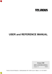
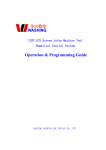
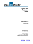
reliability, supported by comprehensive diagnostics. Figure 1-1 indicates the range of voice-dataimage inputs to a LINK/2+ System along with different types of network connections. A
LINK/2+ network can integrate a wide variety of inputs into a cost-effective and efficient
solution to a full range of communications problems.
L2UG
6/30/94
1-1
PUBLIC
NETWORK
CHANNELIZED SERVICES
DIGITAL DATA SERVICE (DDS)
PBX
SWITCHED 56 KBPS DDS
ISDN PRIMARY
X.50 SERVICE
VIDEO
FAX
LINK/2+
SYSTEM
OPTIMIZED CONNECTIONS
TO OTHER LINK/2+ NODES
Figure 1-1. LINK/2+ System Connections
PRODUCT FEATURES
LINK/2+ Systems deliver full integration of voice, data, and image transmission over T-1/E-1
facilities (1.544 to 2.048 Mbps), NTT High-Speed Digital Leased Circuit Services (6.312 Mbps),
and lower speed facilities as well (from 4.8 kbps). Fractional T-1/E-1/NTT services are also
supported. LINK/2+ Systems offer automatic alternate routing and other management capabilities
for full and fractional connections through an embedded ARQ control channel. In addition,
asymmetrical and simplex transmission facilities are supported for those applications where
transmit and receive speeds differ for individual channels.
LINK/2+ System features include:
●
Node capacity to as many as 2000 nodes
●
Advanced Bandwidth Management (ABM) for network efficiency
●
Extensive system security
●
Redundant operation to ensure high reliability
Node Capacity
LINK/2+ networks can directly address up to 2000 nodes. The TIME/VIEW 2000 Network
Management System establishes all routing tables and channel connections. Supervisory port
commands are also available for establishing internetwork connections.
1-2
L2UG
6/30/94
Advanced Bandwidth Management (ABM)
The LINK/2+ System provides the following ABM features:
●
Selective routing
●
Grooming
●
Bumping
●
ILP bandwidth contention and pooling
Selective Routing
Selective routing is the process by which routing decisions are made according to the specific
path criteria defined in a channel’s ABM profile. This feature is supported for channels that pass
through transfer nodes. At connection time, the Network Module will test a possible outbound
intermachine link to determine if it meets a channel’s ABM profile requirements. Any
intermachine link failing to meet these requirements is rejected and the next link in the routing
table will be considered. This process continues until a suitable intermachine link is found and
the connection is made, or until all possible outbound links have been rejected and an appropriate
disconnect reason is assigned. The user has the ability to override selective routing path criteria.
For information on defining a channel’s ABM profile, see Advanced Bandwidth Management
Profile Parameters chapter in the LINK/2+ Configuration Planning Manual. For information on
routing, see Routing chapter in the LINK/2+ Configuration Planning Manual.
Grooming
Grooming is the process of disconnecting and reconnecting channels at a time of minimal usage
with the intention of obtaining a more desirable route. The system maintains two user-specified
timetables that represent the grooming disconnect time and grooming reconnect time for each day
of the week. These timetables are checked against the actual time at least once every 60 seconds.
Provided that the system grooming parameter is enabled and the grooming disconnect time has
been reached, the system searches for the first channel with grooming enabled in its ABM profile
which meets certain qualifications. Any channel that does not have grooming enabled in its
ABM profile or does not meet the required conditions remains connected. Any channel(s)
disconnected for grooming will be reconnected when the grooming reconnect time has been
reached.
Dial-up services backup intermachine links will be disconnected at grooming disconnect time if
and only if the primary intermachine link has been restored to in-service status. Once
disconnected, dial-up services backup intermachine links are not reconnected at grooming
reconnect time. Another feature, automatic grooming, provides grooming of switched backup
bindles every 10 minutes. This feature will disconnect the backup bundle when the primary
bundle is stable for 10 minutes and no connections are present on the backup bundle.
Grooming of channels that pass through transfer nodes is supported with certain restrictions
listed in the System Parameters chapter in the LINK/2+ Configuration Planning Manual.
L2UG
6/30/94
1-3
For information on enabling grooming in a channel’s ABM profile, see Advanced Bandwidth
Management Profile Parameters chapter in the LINK/2+ Configuration Planning Manual. For
information on system grooming and specifying grooming disconnect and reconnect times, see
System Parameters chapter in the LINK/2+ Configuration Planning Manual.
Bumping
Bumping is the process that will selectively disconnect (bump) one or more lower level channels,
thereby allowing a higher level channel to connect. The higher level channel connects using the
resources previously allocated to the lower level channel(s). A channel is assigned this bumping
level in its ABM profile.
The bumping process utilizes two schemes: end-to-end and point-to-point. The end-to-end
scheme attempts to locate a single channel that, when bumped, will provide enough bandwidth
for the bumper to reach its destination node. The point-to-point scheme searches for one or more
channels that, when bumped as a group, will satisfy the bumper’s bandwidth requirements to the
next node.
For information on assigning bumping levels, see Advanced Bandwidth Management Profile
Parameters chapter in the LINK/2+ Configuration Planning Manual. To enable system bumping
and select the bumping scheme, see System Parameters chapter in the LINK/2+ Configuration
Planning Manual.
ILP Bandwidth Contention and Pooling
The ILP bandwidth contention feature enables the user to designate ILP DS-0 channels as
bandwidth contention channels.
For information on designating ILP bandwidth contention channels, see Digital Voice and
Channelized Services Parameters chapter in the LINK/2+ Configuration Planning Manual. For
information on enabling ILP bandwidth contention and bandwidth pooling on a system level, see
System Parameters chapter in the LINK/2+ Configuration Planning Manual.
System Security Features
The LINK/2+ System provides the following features for security:
1-4
●
Password protection
●
Gateway and nongateway designation
●
Nodal security
●
Intermachine link security
L2UG
6/30/94
Password Protection
Password protection ensures that unauthorized users do not have access to the LINK/2+ System
via the supervisory terminal. Two levels of password protection correspond to the gateway and
nongateway commands discussed in the following paragraphs. If the supervisory port is
designated as a gateway, users with password 2 can enter gateway and nongateway commands,
while users with password 1 can enter nongateway commands only.
For information on defining passwords, see Chapter 4, Support Commands.
Gateway and Nongateway Designation
The gateway status of the supervisory port determines the types of commands that can be issued
from the node. Gateway status also affects the supervisory computer port, for example, when an
element management system is used. Designating the supervisory port or supervisory computer
port as a gateway enables a device connected to the port to issue gateway commands to the local
node and to remote nodes.
Gateway commands affect node operation, for example, configuration and diagnostic
commands. Gateway commands are divided into two groups:
●
Global gateway commands are accepted by the local node and all remote nodes within the
same network if the supervisory port or supervisory computer port originating the commands
is designated a gateway. Global gateway commands are typically used for diagnostics.
Global gateway commands are noted by a G in the "G" column of the command summary
tables throughout this manual.
●
Nonglobal gateway commands are accepted by a local node if the supervisory port or
supervisory computer port is designated a gateway.
Nonglobal gateway commands are accepted by a remote node in the same network if:
- The supervisory port or supervisory computer port originating the command is designated
a gateway.
- The node number of the node originating the command is on the alarm notification list of
the node receiving the command.
Nonglobal gateway commands are typically used for configuration activities. Nonglobal
gateway commands are noted by a G in the "G" column of the command summary tables
throughout this manual.
Commands that do not affect node operation, for example, display commands, are called
nongateway commands. These commands may be directed to a local or remote node regardless
of the gateway/nongateway status of the supervisory port or the supervisory computer port.
Nongateway commands do not have an entry in the "G" column of the command summary tables
throughout this manual.
NOTE:
L2UG
6/30/94
Supervisory port and supervisory computer port gateway status
cannot be selected via the local supervisory terminal. Gateway
status is initially determined by Network Module DIP switch but can
be changed by a SET GWY or CLR GWY command issued from a
remote node. See Chapter 6, Configuration Commands.
1-5
Nodal Security
Nodal security restricts a LINK/2+ System from accepting global gateway commands. When
nodal security is enabled, all global gateway commands are interpreted by the LINK/2+ System
as nonglobal gateway commands and are accepted only if both:
●
The supervisory port or supervisory computer port originating the command is designated a
gateway.
●
The node number of the node originating the command is on the alarm notification list of the
node receiving the command.
For information on setting and clearing nodal security, see Chapter 6, Configuration Commands.
Intermachine Link Security
Intermachine link security determines whether supervisory port or supervisory computer port
commands issued from remote nodes will be accepted over a specified intermachine link.
Enabling intermachine link security does not affect voice or data communications between
nodes.
For more information on operation when intermachine link security is enabled, see Intermachine
Link Parameters chapter in the LINK/2+ Configuration Planning Manual.
Redundant Operation
All LINK/2+ modules except I/O channel modules are capable of redundant operation. The
following paragraphs describe the types of redundancy available for different modules.
The Network Module, Interlink Module, Voice Processor, Channelized Services Processor,
Integrated Trunk Module, D-Channel Module, and Bypass Module can be configured for
redundant operation. When redundancy is toggled, all channels supported by that module are
first automatically disconnected and then automatically reconnected.
Redundant operation for the Voice Server Module is achieved with pooled redundancy, that is,
connections on a failed Voice Server Module disconnect and reconnect using unassigned
channels on another Voice Server Module.
For the X.50 Server Module, up to four primary and four redundant modules may be installed at
a node. Modules are defined as either primary or redundant via a user entered command. An
algorithm assigns a redundant X.50 Server Module to automatically take over for a failed
primary X.50 Server Module. During redundancy switchover, the X.50 DS-0 channels and X.50
subrate channels remain fully connected.
When a redundant Power Supply Module is installed, both Power Supply Modules for that
Mainframe share the load under normal operation. If either Power Supply Module fails, the
remaining Power Supply Module assumes the full load for that Mainframe without traffic
interruption.
1-6
L2UG
6/30/94
Redundant operation of any of these modules occurs automatically when a failure is detected in
the primary module. Redundant operation may also be activated via operator initiated command
except for the Voice Server Module.
The Integrated Trunk and D-Channel Modules implement a form of redundancy called cold
standby. When a primary Integrated Trunk Module or D-Channel Module fails, the redundant
module comes online automatically. Integrated Trunk Module proprietary bundles are dropped
and reconnected automatically.
Redundant Digital Termination Modules or Link Framing Modules can be used with redundant
Interlink Modules, Voice Processors, Integrated Trunk Modules, and Channelized Services
Processors. If either of the primary modules fails, the redundant pair of modules assumes
operation. Some Digital Termination Module and Link Framing Module models have two
independent units on a single module, allowing vertical redundancy. See the Modules section of
the LINK/2+ Installation and Maintenance Manual for further information on redundancy
capabilities of these modules.
FUNCTIONAL DESCRIPTION
The following paragraphs describe the function of all units and modules comprising a LINK/2+
System. A functional block diagram of a typical LINK/2+ System is shown in Figure 1-2.
Mainframe
The Mainframe provides mounting and connectors for all modules. Mainframes are available
with 6 slots (microLINK/2+), 13 slots (miniLINK/2+), or 18 slots. As shown in Figure 1-4, 18slot Mainframe systems can include a Control Mainframe and one or two Expander Mainframes.
See the LINK/2+ Configuration Planning Manual for information on the number and types of
modules that can be installed in each Mainframe.
The Line Termination System (LTS) Chassis is a special type of Mainframe designed to
accommodate up to 12 Line Termination Modules. An LTS Chassis is required when Subrate
Channel Processors are installed in the LINK/2+ Mainframe (see "Data I/O Channel Modules"
paragraph for a description of the Subrate Channel Processor). The LTS Chassis can be
collocated with the LINK/2+ Mainframe or installed in a separate rack within cabling distance
(approximately 50 feet) of the LINK/2+ Mainframe.
Fan Housing
The Fan Housing provides cooling for the 13-slot and 18-slot Mainframes. The 6-slot Mainframe
has a Fan Tray Module which is integral to the Mainframe.
L2UG
6/30/94
1-7
EXPANDER A MAINFRAME
BUS
EXPANDER
TO I/O
DEVICES
DRIVER
MODULE
I/O
CHANNEL
MODULE(S)
C
O
M
M
O
N
B
U
S
VOICE
PROCESSOR(S)
VOICE SERVER
MODULE(S)
LINE
DRIVER
DS-1/E-1
TRUNK
CSU
X.50
SERVER
MODULE(S)
D-CHANNEL
MODULE(S)
CONTROL MAINFRAME
BUS
EXPANDER
TO I/O
DEVICES
TO LINK/CSU
(OPTIONAL)
I/O
CHANNEL
MODULE(S)
NETWORK
MODULE
TO
SUPERVISORY
TERMINAL
TO
SUPERVISORY
COMPUTER
BYPASS
MODULE
TO STATION
CLOCKS
X.50
SERVER
MODULE(S)
BUS
EXPANDER
INTERLINK
MODULE(S)
DRIVER
MODULE
C
O
M
M
O
N
B
U
S
LINE
DRIVER
INTEGRATED
TRUNK
MODULE(S)
LINE
DRIVER
VOICE
PROCESSOR(S)
LINE
DRIVER
CHANNELIZED
SERVICES
PROCESSOR(S)
LINE
DRIVER
CSU
OR
DSU
INTERMACHINE
LINK
DS-1/E-1
TRUNK
CSU
DS-1/E-1
TRUNK
CSU
DS-1/E-1
TRUNK
CSU
VOICE SERVER
MODULE(S)
D-CHANNEL
MODULE(S)
EXPANDER B MAINFRAME
EXPANDER B MAINFRAME IS FUNCTIONALLY
EQUIVALENT TO EXPANDER A MAINFRAME
NOTES:
= LINE DRIVER CAN BE DIGITAL TERMINATION MODULE,
LINK FRAMING MODULE, BIPOLAR INTERFACE MODULE,
OR FACILITY INTERFACE MODULE.
CSU = CHANNEL SERVICE UNIT
DSU = DIGITAL SERVICE UNIT
Figure 1-2. Functional Block Diagram of Typical LINK/2+ System
1-8
L2UG
6/30/94
Power Supply Chassis and Power Supply Module
The Power Supply Chassis provides mounting for Power Supply Module(s) for 18-slot
Mainframes. Power Supply Modules for 6-slot and 13-slot Mainframes are integral to the
Mainframe.
The Power Supply Module converts AC power into regulated +5 VDC and ±12 VDC required
for operating a Mainframe. The Power Supply Module is the switching regulator type and
incorporates control and logic circuits that provide for load sharing when a redundant Power
Supply Module is installed (13-slot and 18-slot Mainframes only). If a Power Supply Module
failure is detected, control is transferred to the redundant Power Supply Module without
interruption of power to that Mainframe.
Network Module
The Network Module exercises primary microprocessor control over the LINK/2+ System. The
Network Module processes commands from the supervisory terminal or supervisory computer,
and provides the system clocks via phase locked loop.
●
The Network Module supervisory port permits an attached asynchronous ASCII terminal or
microcomputer to communicate with the Network Module microprocessor. The supervisory
computer port permits the TIME/VIEW Network Management System (NMS) to
communicate with the Network Module microprocessor. A supervisory terminal or network
management system can access stored information to:
- Define or display programming parameters
- Display network configuration and connect status
- Connect or disconnect channels
- Define channel, bundle, and intermachine link routing
- Initiate diagnostic tests and display test results
A microcomputer attached to the supervisory port can be used to download operational
software to the Network Module, Interlink Module, Integrated Trunk Module, VSM.3 and
VSM.5 Voice Server Modules, and X.50 Server Module.
●
The Network Module external port can be used to connect to a LINK Channel Service Unit
(LINK/CSU). The LINK/CSU is an intelligent channel service and digital service unit
combination that is programmable for either extended superframe (ESF) or D4 framing
format. The LINK/CSU frees up slots in the LINK/2+ System Mainframe and provides up to
28 nonredundant or 14 redundant CSUs.
A LINK/2+ supervisory terminal or network management system can issue commands to the
LINK/CSUs in the network. For information on the LINK/CSU, see the LINK/CSU User’s
Guide.
L2UG
6/30/97
1-9
●
The Network Module station clock port allows one or two external clock sources (station
clocks) to be connected to the Network Module. The LINK/2+ System can be programmed to
use these station clocks to provide system clocking. Station clock speeds between 2400 bps
and 2.048 Mbps are supported.
Driver Module
Driver Modules provide the interface between the 18-slot Control Mainframe and Expander
Mainframe(s). When Expander Mainframes are used, a Driver Module must be installed in the
Control Mainframe and in each Expander Mainframe.
Interlink Module
The Interlink Module provides the interface between the common bus and an intermachine link.
The Interlink Module assembles the data frame, maintains intermachine link synchronization,
and transfers data between the I/O channels and that intermachine link.
Interlink Modules are available that can be configured for:
●
Symmetrical operation in which the transmit and receive speeds are the same
●
Asymmetrical operation in which the transmit and receive speeds are different
●
Simplex operation in which data is either transmitted or received but not both
A Satellite Buffer option for the Interlink Module provides additional buffer capability which
compensates for variable delay times commonly associated with satellite transmissions.
Digital Termination Module
The Digital Termination Module interfaces with unframed North American T-1 or European
megabit service. The module is available in both single and dual unit configurations. The Digital
Termination Module interfaces directly with a CSU. For digital radio facilities, the Digital
Termination Module interfaces directly with the DSX-1 interface of the transceiver.
Link Framing Module
The Link Framing Module (models LFM and LFM.1) interfaces with unframed or framed T-1
service. The LFM and LFM.1 Modules support D4 framing requirements of AT&T PUB 62411.
The LFM Module supports ESF format as defined in Government of Canada Department of
Communications specification CS-03.
An Equalizer Linedriver Module can be used with an LFM Module to meet Government of
Canada Department of Communications specification CS-03 Issue 6 Supplement B Amendment
3 for connection to common carrier at distances up to 655 feet (200 meters).
The LFM.3 Link Framing Module interfaces with 2.048 Mbps digital services that conform to
CCITT recommendation G.704.
1-10
L2UG
6/30/94
The LFM.5 and LFM.6 Link Framing Modules interface with the Nippon Telephone and
Telegraph (NTT) Branching T-1 service. For further information on these modules, see the Link
Framing Module Model LFM.5 and Link Framing Module Model LFM.6 User’s Manuals.
The LFM.9 Link Framing Module provides independent station clock at 1.544 MHz to major
nodal hubs in a network. The LFM.9 provides clock from one of two inputs to up to eight nodes.
The module can switch between inputs without causing a clock fallback at the Network Module
if one input fails.
The LFM.10, LFM.11, and LFM.12 Link Framing Modules provide n x 64 kbps or n x 56
kbps bundled output over T-1 facilities to enable low-cost access to fractional T-1 service. These
modules create user-selected bundle sizes from 1 to 24 DS-0 channels at speeds from 56 kbps to
1.544 Mbps. Release 7 and later Link Framing Modules (LFM.10, LFM.11, and LFM.12) are
software programmable. Pre-release 7 modules use DIP switches to set link framing parameters.
For pre-release 7 modules, see the Link Framing Module Models LFM.10, LFM.11, and LFM.12
User’s Manual for DIP switch settings.
The LFM.14 Link Framing Module combines four T-1 links together and provides the framing
and electrical encoding for interfacing to the Japanese NTT High-Speed Secondary Service. This
service allows a single 6.312 Mbps trunk to be divided into multiple n x 64 kbps bundles, where
n ranges from 1 to 24.
Bipolar Interface Module
The Bipolar Interface Modules (BIM.1, BIM.2, and BIM.3) interface a Voice Processor,
Channelized Services Processor, or Integrated Trunk Module to a DSX-1 or G.703 transmission
facility. The Bipolar Interface Module converts the unipolar non-return-to-zero (NRZ) signal
from the Voice Processor, Channelized Services Processor, or Integrated Trunk Module to
alternate mark inversion (AMI) bipolar format.
The Bipolar Interface Module (64 kbps BIM) interfaces the ILC.2 Interlink Module, QSC.2 Quad
Synchronous Module, or QSP.2 Quad Synchronous Processor Module to a G.703 transmission
facility. The 64 kbps BIM supports G.703 64 kbps codirectional and contradirectional coding.
Integrated Trunk Module
The Integrated Trunk Module allows hybrid networking in a LINK/2+ network using industrystandard channelized services. Using the Integrated Trunk Module, networks can take advantage
of public network services while maintaining cost effectiveness and network management
control.
The Integrated Trunk Module uses a flexible, multipurpose channelization format in which
varying numbers of DS-0s are grouped into proprietary and nonproprietary bundles. The
Integrated Trunk Module can support up to 24 proprietary bundles per physical link, 24 DS-0
nonproprietary bundles per T-1 link, or 31 DS-0 nonproprietary bundles per E-1 link. The
Integrated Trunk Module supports Switched 56K service, ISDN primary rate, and byte
alignment.
L2UG
6/30/94
1-11
Integrated Trunk Modules support configurations for:
●
T-1/NTT operation, where the module (ILQ.1) supports line transmission rates of up to
1.544 Mbps for use in North American (T-1) and Japanese (NTT) networks
●
E-1 operation, where the module (ILQ.2) supports line transmission rates of up to 2.048
Mbps for use in European (CEPT) networks
D-Channel Module
The D-Channel Module establishes the B-channel and/or H0-channel connections between two
nodes as well as the signaling support for one of the 24 or 31 time slots on the Integrated Trunk
Module.
The D-Channel Module supports multiple Q.931 protocols, including 4ESS, 5ESS, NTT,
NUMERIS, DMS250/100, and Austel. The D-Channel Module supports carriers in different
countries including AT&T in the United States, NTT in Japan, AOTC in Australia, and France
Telecom.
Voice Processor
The Digital Voice Processor Module (Voice Processor) transfers DS-0 channels via time slot
interchange between other LINK/2+ System modules and a DS-1 trunk. DS-0 channels can be
locally or remotely connected to other DS-0 channels, Quad Voice Module channels, Enhanced
Voice Module channels, Quad Synchronous Module channels, or Quad Synchronous Processor
channels. A Voice Processor with ADPCM capability can convert PCM channels to ADPCM
channels on a per channel basis to provide more efficient bandwidth utilization. Voice Processor
channels can be processed by a Voice Server Module to achieve greater voice compression and
echo cancellation. The Voice Processor can connect to a Digital Termination Module, Link
Framing Module, or LINK/CSU.
The ILP.8 and ILP.13 Voice Processors provide access to Japanese TTC (Telecommunications
Technology Committee) formatted PBXs.
A Facility Interface Module (FIM.1) is used with an ILP.8 or ILP.13 Voice Processor to
provide electrical translation and isolation between the Voice Processor and the 2.048 Mbps TTC
trunk.
1-12
L2UG
6/30/94
Analog Voice I/O Channel Modules
The following analog voice I/O channel modules can be used in a LINK/2+ System:
●
The Quad Voice Module converts analog voice signals to digital signals and vice versa using
16 kbps voice compression, continuously variable slope delta (CVSD) modulation, pulse code
modulation (PCM), or adaptive differential pulse code modulation (ADPCM), depending on
the model. In PCM mode, the Quad Voice Module produces a 64 kbps rate output for
scanning by either the Voice Processor, Integrated Trunk Module, or Channelized Services
Processor. Each Quad Voice Module contains four individual I/O voice channels. E & M
interfacing for each I/O voice channel is included on the module. Quad Voice Module
channels can be processed by a Voice Server Module to achieve greater voice compression
and echo cancellation.
●
The Enhanced Voice Module converts analog voice and Group III facsimile (fax) signals to
digital signals and vice versa using voice compression or pulse code modulation (PCM). Each
Enhanced Voice Module contains four individual I/O channels. Voice compression can be
specified on a per channel basis, with compression rates of 6 kbps, 8 kbps, or 16 kbps at each
channel.
Echo cancellation can be specified on a per channel basis. E & M interfacing for each I/O
voice channel is included on the module. In PCM mode, the Enhanced Voice Module
produces a 64 kbps rate output for scanning by either the Voice Processor, Voice Server
Module, Integrated Trunk Module, or Channelized Services Processor.
Models EVM.2 and EVM.3 accept and convert fax signals for on-board compression and
transmittal through the network. All Enhanced Voice Modules can accept fax signals for
compression through the VSM.1 or VSM.3 Voice Server Module. Model EVM.3 also
supports nonstandard fax functions beyond the Group III standard.
●
The Foreign Exchange Office Module accepts four 2-wire loop or ground start analog voice
circuits for conversion to digital signals and vice versa using voice compression or pulse code
modulation (PCM).
- For the FXO Foreign Exchange Office Module, voice compression can be specified on a
per channel basis with rates of 8 kbps or 16 kbps using adaptive sub-band excited
transformation (ASET) compression..
- For the FXO.1 Foreign Exchange Office Module, voice conversion is provided for each
channel using 64 kbps PCM.
- For the FXO.3 Foreign Exchange Office Module, voice compression can be specified on a
per channel basis with rates of 5.33 kbps or 8 kbps using codebook excited linear
prediction (CELP) compression and 16 kbps using adaptive transform coding (ATC)
compression.
When FXO channels are directed to the VSM.1 or VMS.3 Voice Server Module by voice
profile programming, fax transmissions are also accepted.
An FXO/Network Termination Module is supplied with a Foreign Exchange Office Module
for connection to the Central Office.
L2UG
6/30/94
1-13
●
The Foreign Exchange Station Module accepts four 2-wire loop or ground start analog
voice circuits for conversion to digital signals and vice versa using voice compression or
pulse code modulation (PCM).
- For the FXS Foreign Exchange Station Module, voice compression can be specified on a
per channel basis with rates of 8 kbps or 16 kbps using ASET compression.
- For the FXS.1 Foreign Exchange Station Module, voice conversion is provided for each
channel using 64 kbps PCM.
- For the FXS.3 Foreign Exchange Station Module, voice compression can be specified on a
per channel basis with rates of 5.33 kbps or 8 kbps using CELP compression and 16 kbps
using ATC compression.
When FXS channels are directed to the VSM.1 or VSM.3 Voice Server Module by voice
profile programming, fax transmissions are also accepted.
An FXS/Network Termination Module is supplied with a Foreign Exchange Station
Module for connection to the Subscriber.
●
The QVC Voice Module converts analog voice signals to digital signals and vice versa using
CVSD modulation. Each QVC Voice Module contains four individual I/O voice channels.
Two E & M Interface Modules are also supplied. Each E & M Interface Module handles two
I/O voice channels.
Voice Server Module
The Voice Server Module provides voice compression, echo cancellation, and fax transmission
for Voice Processor and Integrated Trunk Module channels as well as for Quad Voice Module,
Enhanced Voice Module, Foreign Exchange Office Module, and Foreign Exchange Station
Module I/O channels.
The VSM and VSM.1 Voice Server Modules compress a 64 kbps channel to 8 or 16 kbps, with
or without echo cancellation, using ASET compression. Each Voice Server Module supports up
to 31 channels. In addition to voice, the VSM.1 Voice Server Module supports up to eight
simultaneous Group III facsimile (fax) connections. The VSM.1 Voice Server Module monitors
for fax transmission and switches automatically from voice to fax operation.
The VSM.3 Voice Server Module compresses a 64 kbps channel to 5.33 or 8 kbps using CELP
compression and 16 kbps using ATC compression, with or without echo cancellation. Each
VSM.3A Voice Server Module supports up to 8 channels and each VSM.3B Voice Server
Module supports up to 16 channels. In addition to voice, the VSM.3 Voice Server Module
supports nonstandard fax or Group III fax connections. The VSM.3 Voice Server Module
monitors for fax transmission and switches automatically from voice to fax transmission.
The VSM.5 Voice Server Module is capable of two modes of operation, clear mode and STUIII Secure Mode. In clear mode, the VSM.5 compresses a 64 kbps PCM channel to 4.8 or 9.6
kbps using VCELP compression, with or without echo cancellation. In the STU III Secure Mode,
the VSM.5 can transport encrypted secure voice and data at rates of 2.4, 4.8, or 9.6 kbps. Each
VSM.5 Voice Server Module supports up to 12 channels. The VMS.5 Voice Server Module
monitors the modem signal and dynamically switches between clear and secure modes without
user intervention.
1-14
L2UG
6/30/97
NOTE:
The VSM.3 and VSM.5 CELP compression schemes are not
compatible with each other.
If multiple Voice Server Modules are installed, they operate in a pooled redundancy mode.
Channelized Services Processor
The Channelized Services Processor scans for, constructs, and transfers contiguous and
noncontiguous 64 kbps bundles between the D4 or G.732 formatted devices and a DS-1/E-1
trunk in a framed format at either 1.544 or 2.048 Mbps. In an appropriate bundle configuration,
the Channelized Services Processor supports fractional T-1 applications. See the LINK/2+
Configuration Planning Manual for information on bundle configurations. The Channelized
Services Processor can connect to a Digital Termination Module, Link Framing Module, or
LINK/CSU.
X.50 Server Module
The X.50 Server Module takes 64 kbps X.50 framed DS-0 channels from the X.50 network
locally via an Interlink Module, Integrated Trunk Module, Channelized Services Processor,
Voice Processor, Quad Synchronous Processor Module, or Quad Synchronous Module and
demultiplexes the X.50 DS-0 channels into synchronous X.50 subrate channels of 2400, 4800,
9600, or 19200 bps.
The X.50 subrate channels can be:
• Passed on to a Quad Synchronous Processor Module or Quad Synchronous Module for use by
a local I/O device (local subrate drop).
• Remultiplexed by an Integrated Trunk Module (via a Bypass Module) or Interlink Module for
transmission over a T-1 or E-1 network (bridge, or remote subrate drop).
• Passed through the Bypass Module and back to an X.50 Server Module to be remultiplexed
by the X.50 Server Module and sent to the X.50 network via another Voice Processor
Module, Quad Synchronous Processor Module, or Quad Synchronous Module (drop and
insert).
Each X.50 Server Module supports up to 16 X.50 Division 2 or Division 3 framed DS-0
channels. Up to four primary and four redundant X.50 Server Modules can be installed at a node.
Bypass Module
The Bypass Module provides channel bypassing capability at a node. Full duplex data and
control functions originating at one node may be routed through as many as seven intermediate
bypass nodes to a destination node.
The local and remote connections of the Channelized Services Processor or Integrated Trunk
Module to the Interlink Module or another Channelized Services Processor or Integrated Trunk
Module are also established via the Bypass Module.
L2UG
6/30/97
1-15
Data I/O Channel Modules
The following data I/O channel modules can be used in a LINK/2+ System:
●
The Quad Synchronous and Dual Synchronous Modules provide the interface between I/O
data channels and the common bus. Each Quad Synchronous Module contains four individual
synchronous I/O data channels. Each Dual Synchronous Module contains two high speed
synchronous I/O data channels. The Quad Synchronous and Dual Synchronous Modules have
the ability to supply n x 64 kbps rates to be formatted in bundles by the Channelized Services
Processor and placed on a DS-1/E-1 trunk. The Quad Synchronous Module can supply n x 56
kbps or n x 64 kbps rates for placement on a T-1 or E-1 interface by the Integrated Trunk
Module.
The QSC.7 Quad Synchronous Module has a single application of converting 56 kbps
subrate data channels into 64 kbps logical DS-0 channels.
●
The Quad Synchronous Processor provides the interface between I/O data channels and the
common bus. Each Quad Synchronous Processor contains four individual synchronous I/O
data channels supporting the range of data rates from 50 bps to 1.984 Mbps. All ports can
operate simultaneously at 1.984 Mbps. The Quad Synchronous Processor has the ability to
supply n x 64 kbps rates to be formatted in bundles by the Channelized Services Processor
and placed on a DS-1/E-1 trunk. The Quad Synchronous Processor has the ability to supply
n x 56 kbps or n x 64 kbps rates to be formatted in bundles by the Integrated Trunk Module
and placed on a DS-1/E-1 trunk. The Quad Synchronous Processor can be configured for
symmetrical, asymmetrical, or simplex operation.
Individual channels on a Quad Synchronous Processor can be configured to operate in the
following special modes:
- Broadcast/polling mode—In broadcast/polling mode, a single channel at a central host
site can connect to multiple remote channels called a nest poll group. The channels
forming the nest poll group must reside in the same nest (LINK/2+ Mainframe). The
communication between the host channel and the remote nest poll group uses only one
time slot in the connecting intermachine link. When the host channel transmits, all nest
poll group channels receive the transmission. Only one nest poll group channel can
transmit at a time.
- 56K/64K mode—Switched 56K service provides 56 kbps of data communication on a
dial-up basis. In switched 56K and nonswitched 56K modes, data is always transmitted at
56 kbps. In switched 56K mode, the Quad Synchronous Processor performs speed
translation from 56 kbps to 64 kbps (DS-0) format by "stuffing" the eighth bit with
signaling and dialing information received from a Terminal Interface Unit (TIU). In
nonswitched 56K mode, the eighth bit is stuffed with a 1. A Quad Synchronous Processor
operating in switched 56K mode can be scanned by an Interlink Module (for networking to
a remote node) or by a Voice Processor, Integrated Trunk Module, or Channelized
Services Processor.
- LPDA-1 mode—LPDA-1 (Link Problem Diagnostic Aid) is an IBM test protocol that
allows a front end processor (FEP) to obtain test information from a pair of remote
modems. In LPDA-1 mode, the Quad Synchronous Processor channel allows function
transmission in inband mode which guarantees compliance with ones density. Any
transition of the function lead (F3 IN) will be communicated from the FEP to the modem
1-16
L2UG
6/30/94
to start test mode, even if the Quad Synchronous Processor channel is in data mode. Test
mode continues until another transition of the F3 IN function is sent by the FEP.
- Simplex broadcast mode—In simplex broadcast mode, a single originator channel at one
node can connect to multiple terminator channels at other nodes. When the originator
channel transmits, all terminator channels receive the transmission, but the terminator
channels cannot transmit back to the originator.
●
The Quad Asynchronous Module provides the interface between I/O data channels and the
common bus. Each Quad Asynchronous Module contains four individual asynchronous I/O
data channels.
●
The Dual Isochronous Module provides the interface between I/O data channels and the
common bus. Each Dual Isochronous Module contains two I/O data channels that can be
independently configured for isochronous, plesiochronous, or asynchronous operation.
●
The Isochronous Communication Module provides the interface between I/O data channels
and the common bus. Each Isochronous Communication Module contains two I/O data
channels that can be independently configured for isochronous or plesiochronous operation.
The Isochronous Communication Module provides frequency discrimination, I/O rates up to
1.544 Mbps, plus more speeds than available on the Dual Isochronous Module.
●
The Subrate Channel Processor is intended for generation of 64 kbps DS-0 channels from
customer subrate data and 56 kbps data in a DDS environment. The Subrate Channel
Processor can support DS-0A or DS-0B signal formats and any mix of primary/secondary
channel capability.
- In DS-0A configuration, the Subrate Channel Processor emulates the Office Channel Unit
(OCU) functionality. Four independent ports at the standard subrates (2.4, 4.8, or 9.6
kbps), secondary port rates (3.2, 6.4, or 12.8 kbps), and 56/72 kbps are supported,
depending on the model. On a per port basis, a 64 kbps DS-0 channel is generated. The
overall throughput is 256 kbps (four DS-0 channels). Data to and from the network is
carried over four independent DS-0A formatted channels through an Interlink Module or
Voice Processor.
- In DS-0B configuration, the Subrate Channel Processor integrates the functionality of the
OCU and Subrate Data Multiplexers (SRDM). Up to five standard subrates or secondary
port rates are multiplexed into a single 64 kbps channel. Data to and from the network is
carried over a single DS-0B formatted channel through an Interlink Module, Integrated
Trunk Module, or Voice Processor.
A Line Termination Module is required to terminate the Subrate Channel Processor
connection. Each Line Termination Module supports up to two Subrate Channel Processors.
Line Termination Modules are installed in a separate LTS Chassis (see "Mainframe"
paragraph).
SPECIFICATIONS
The LINK/2+ System operates as a microprocessor based synchronous, time division, character
interleaved multiplexer. A nonvolatile memory maintains the user programmed database for
approximately 45 days (between 0° and 60° C) without AC power.
Table 1-1 lists additional specifications for each Mainframe type.
L2UG
6/30/94
1-17
Table 1-1. Specifications
Specification
Physical
Configuration
Size
18-Slot LINK/2+ System
Rack mounted only
Rack mounted only
Control Mainframe or Expander
Mainframe: 13 1/8" (33.3 cm)
high by 19" (48 cm) wide by
20 1/4" (51.6 cm) deep
Mainframe: 13 1/8" (33.3 cm)
high by 19" (48 cm) wide by
20 1/4" (51.6 cm) deep
Fan housing: 5 1/4" (13.3 cm)
high by 19" (48 cm) wide by
20 1/4" (51.6 cm) deep
Power Supply Chassis: 7" (17.8
cm) high by 19" (48 cm) wide by
20 1/4" (51.6 cm) deep
Weight
13-Slot miniLINK/2+ System
Control Mainframe or Expander
Mainframe (without internal
power supplies or modules):
24.5 lbs (11.1 kg)
Fan Housing: 3 1/2" (8.9 cm) high
by 19" (48 cm) wide by 16 1/2"
(41.9 cm) deep
Power Supply Chassis
(optional; used for -48 VDC
E & M Power Supply Module):
7" (17.8 cm) high by 19" (48 cm)
wide by 20 1/4" (51.6 cm) deep
Mainframe (without internal
power supplies or modules):
24.5 lbs (11.1 kg)
6-Slot microLINK/2+ System
Free standing with case
Rack mounted without case
With case: 23 1/4" (59 cm)
high by 8 3/8" (21.3 cm) wide by
24 3/4" (62.9 cm) deep
Floor plate: 13 3/8" (34 cm) wide
Without case: 22 3/4" (57.8 cm)
high by 6 3/4" (17.1 cm) wide by
20 3/8" (51.8 cm) deep
With case: 60 lbs (27.2 kg)
Without case: 33 lbs (15 kg)
Typical Module: 2.5 lbs (1.1 kg)
Typical Module: 2.5 lbs (1.1 kg)
Fan Housing: 6.5 lbs (2.95 kg)
Fan housing: 10 lbs (4.5 kg)
Power Supply Chassis: 16.6
lbs (7.5 kg)
Power Supply Module: 18.5
lbs (8.4 kg)
Power Requirements
1-18
Power Supply Module: 18.5
lbs (8.4 kg)
Power Supply Chassis
(optional; used for -48 VDC
E & M Power Supply Module):
16.6 lbs (7.5 kg)
Each Mainframe:
• 115/230 VAC Power Supply
Module: 115 +10 VAC at 12A
or 230 +20 VAC at 6A, 47 to
63 Hz, single phase
115/230 VAC Power Supply
Module: 115 + 10 VAC at 12A or
230 +20 VAC at 6A, 47 to 63 Hz,
single phase
• 100/200 VAC Power Supply
Module: 100 VAC +10 VAC at
15A or 200 +20 VAC at 8A, 47
to 63 Hz, single phase
100/200 VAC Power Supply
Module: 100 VAC +10 VAC at
15A or 200 +20 VAC at 8A, 47 to
63 Hz, single phase
• -48 VDC Power Supply
Module: input 42 to 58 VDC
not to exceed 24A
-48 VDC Power Supply
Module: input 42 to 58 VDC
not to exceed 24A
-48 VDC E & M Power Supply
Module for certain voice signaling
types: 115 +10 VAC at 3A or 230
+20 VAC at 1.5A, 47 to 63 Hz,
single phase
-48 VDC E & M Power Supply
Module for certain voice signaling
types: 115 +10 VAC at 3A or 230
+20 VAC at 1.5A, 47 to 63 Hz,
single phase
115/230 VAC Power Supply
Module: 115 +10 VAC at 5A or
230 +20 VAC at 2.5A, 47 to 63
Hz, single phase
-48 VDC Power Supply Unit for
certain E & M voice signaling
types: 115 +10 VAC at 0.25A or
230 + 20 VAC at 0.125A, 47 to 63
Hz, single phase
L2UG
6/30/94
Table 1-1. Specifications (Cont’d)
Specification
Power Requirements
(Cont’d)
Power Consumption
Heat Dissipation
Environmental
Requirements
L2UG
6/30/94
18-Slot LINK/2+ System
Fan Assembly:
• 115 +10 VAC at 0.9A or 230
+20 VAC at 0.45A, 47 to 63 Hz,
single phase
• -48VDC: 0.4A at 48 VDC
1000 watts maximum per
Mainframe
13-Slot miniLINK/2+ System
6-Slot microLINK/2+ System
Fan Assembly: 115 +10 VAC at
0.5A or 230 +20 VAC at 0.25A
Fan Assembly, -48VDC: 0.3A at
48 VDC
685 watts maximum per chassis
280 watts maximum
80 watts maximum per -48 VDC
E & M Power Supply Module
30 watts maximum per -48 VDC
Power Supply Unit
2330 BTUs/hour (685 watts)
maximum plus 280 BTUs/hour (80
watts) maximum per -48 VDC
E & M Power Supply Module
958 BTUs/hour (280 watts)
maximum plus 103 BTUs/hour (30
watts) maximum per -48 VDC
Power Supply Unit
Ambient operating temperature
from 0° to 45° C
Ambient operating temperature
from 0° to 45° C
Relative humidity to 95%
(noncondensing)
Relative humidity to 95%
(noncondensing)
Relative humidity to 95%
(noncondensing)
Altitude to 12,000 ft. (3660 m)
Altitude to 12,000 ft. (3660 m)
Altitude to 12,000 ft. (3660 m)
250 watts maximum per -48 VDC
E & M Power Supply Module
3400 BTUs/hour (1000 watts)
maximum per Mainframe plus 850
BTUs/hour (250 watts) maximum
per -48 VDC E & M Power Supply
Module
Ambient operating temperature
from 0° to 45° C
1-19
Chapter
2
Getting Started
Information you need to start using the LINK/2+ System is contained in this chapter:
●
Power application and turn-off
●
Self-test and other start-up activities
●
Accessing the supervisory port
●
Supervisory port log in and log out
●
Loading Network Module/Interlink Module operational software
●
Loading Integrated Trunk Module operational software
●
Loading X.50 Server Module operational software
●
Loading VSM.3 and VSM.5 Voice Server Module operational software
●
Opening and closing Mainframe door
This chapter assumes the LINK/2+ System has already been properly configured and installed. If
not, see the LINK/2+ Configuration Planning Manual and the Installation section of the LINK/2+
Installation and Maintenance Manual.
Day-to-day management of the LINK/2+ System can be performed via the integral supervisory
port or the optional TIME/VIEW 2000 Network Management System. This manual discusses
supervisory port operation only. For information on using TIME/VIEW, see the TIME/VIEW
2000 documentation.
Typical network management activities that the operator can perform from the supervisory
terminal once the LINK/2+ System is powered up include:
●
Monitoring system status and alarm messages. See Chapter 5, Display Commands.
●
Connecting/disconnecting channels and performing other configuration activities. See
Chapter 6, Configuration Commands.
●
Performing diagnostic tests. See Chapter 7, Diagnostic Commands.
POWER APPLICATION AND TURN-OFF
Procedure 2-1 defines the power turn-on sequence for each LINK/2+ System. Procedure 2-2
defines the power turn-off sequence.
L2UG
6/30/97
2-1
Procedure 2-1. Power Turn-On
1.
Ensure that all channel devices and external line drivers are turned on and operational.
2.
If local supervisory terminal is to be used, ensure that terminal is turned on and operational.
3.
For 18-slot Mainframes, remove power supply grille.
For 13-slot (miniLINK/2+) Mainframes, open Mainframe door.
4.
For 18-slot and 13-slot Mainframes, set POWER switch on Power Supply Module(s) to 1
and observe that:
●
POWER ON (green) indicator is lit.
●
ON LINE (green) indicator is lit on in-control Power Supply Module.
●
LOAD SHARE (yellow) indicator is lit on in-control Power Supply Module
(redundancy) or is off if only a single Power Supply Module (no redundancy) is
installed.
Go to step 6.
5.
For 6-slot (microLINK/2+) Mainframes:
A. Ensure power cord from Power Supply Module is connected to rear of Fan Tray
Module.
B.
Apply power by connecting power cord from Fan Tray Module to AC power source.
C. Ensure that both fans in Fan Tray Module are rotating.
PRECAUTION:
If one or both of the fans fail to operate, unplug the
power cord from rear of chassis immediately. See Fan
Tray Module replacement procedure in the LINK/2+
Installation and Maintenance Manual.
6.
The LINK/2+ System performs a self-test. (See "Self-Test" paragraph.) If the self-test is
successful, the LINK/2+ System is ready for operation. If an error occurs, see the
Troubleshooting chapter in the LINK/2+ Installation and Maintenance Manual.
7.
If Line Termination System (LTS) Chassis and Line Termination Modules are installed,
connect -48 VDC power source at rear of chassis.
8.
For 18-slot Mainframes, reinstall power supply grille.
For 13-slot Mainframes, close Mainframe door.
Procedure 2-2. Power Turn-Off
1.
2-2
Notify all concerned parties that the LINK/2+ System is being shut down.
L2UG
6/30/94
2.
If LTS Chassis and Line Termination Modules are installed, disconnect -48 VDC power
source at rear of chassis.
3.
For 18-slot Mainframes, remove power supply grille.
For 13-slot (miniLINK/2+) Mainframes, open Mainframe door.
4.
For 18-slot and 13-slot Mainframes, set POWER switch on Power Supply Module(s) to 0.
For 6-slot (microLINK/2+) Mainframes, disconnect power cord from AC power source.
All indicators go off.
SELF-TEST AND OTHER START-UP ACTIVITIES
The following paragraphs discuss activities that occur after system start-up and during system
operation:
●
Self-test
●
Bit error rate (BER) test
●
Channel connections
●
Alarm indicators and messages
Self-Test
When power is applied to the LINK/2+ System, the Network Module ON LINE indicator lights
and the system automatically resets and runs a self-test diagnostic procedure The self-test routine
checks the hardware and firmware of the following modules:
L2UG
6/30/94
●
Network Module
●
Interlink Module
●
Integrated Trunk Module
●
X.50 Server Module
●
Voice Processor
●
D-Channel Module
●
Channelized Services Processor
●
Enhanced Voice Module
●
Voice Server Module
●
Dual Isochronous Module
2-3
●
Isochronous Communication Module
●
Foreign Exchange Office Module
●
Foreign Exchange Station Module
●
Quad Asynchronous Module
The supervisory terminal lists each test as it is performed on the Network Module in the
following order:
NCL BOOT STARTUP TESTS
RAM - OK
PROM - OK
NCL STARTUP TESTS
UART - OK
ECP - OK
DATABASE - OK D2
RTC - OK
PLL - OK
NOTES: The "68020 - ERROR" message is displayed only if one of the 68020
CPU diagnostic tests fail.
The "DIP SWITCH 8 OFF" message is displayed only if DIP Switch
K1-8 on the Network Module is incorrectly set to the OFF/OPEN
position.
The "ERROR BATTERY" message is displayed only if one, or both,
batteries on the Network Module are defective or low in voltage.
●
If the Network Module self-test is satisfactory and passwords have been previously defined:
- Module comes online.
- Message, LINK/2 (or microLINK/2) Supervisory Port On-Line, appears on the supervisory
terminal.
- Password prompt (ENTER PASSWORD:) appears. See "Supervisory Port Log In"
paragraph.
After password is entered correctly:
- Time and date appear on the supervisory terminal.
- Prompt (Nxxxx>) appears. (xxxx is the local node number.)
●
If the Network Module self-test is satisfactory and passwords have not been previously
defined:
- Module comes online.
2-4
L2UG
6/30/97
- Message, LINK/2 (or microLINK/2) Supervisory Port On-Line, and time and date appear
on the supervisory terminal.
- Prompt (Nxxxx>) appears.
●
If the Network Module self-test is NOT satisfactory and a redundant Network Module is
installed, the LINK/2+ System switches to the redundant Network Module. The supervisory
terminal lists the self-test messages for this Network Module.
●
If any error messages appear or alarm indicators light, see the Troubleshooting chapter in the
LINK/2+ Installation and Maintenance Manual.
Self-tests of the Interlink, Integrated Trunk, D-Channel, Voice Processor, Channelized Services
Processor, Dual Isochronous, Isochronous Communication, Enhanced Voice, Foreign Exchange
Office, Foreign Exchange Station, Quad Asynchronous, Voice Server, and X.50 Server Modules
are run during the Network Module self-test, but no messages are displayed on the supervisory
terminal for these modules.
●
If the self-tests of the Interlink, Integrated Trunk, D-Channel, Voice Processor, Channelized
Services Processor, Isochronous Communication, Enhanced Voice, Foreign Exchange Office,
Foreign Exchange Station, Voice Server, and X.50 Server Modules are satisfactory:
- Module’s ON LINE indicator lights.
- Module comes online.
●
If the self-tests of the Dual Isochronous and Quad Asynchronous Modules are satisfactory, the
modules come online, but no indicators light.
●
If any error messages appear or alarm indicators light, see the Troubleshooting chapter in the
LINK/2+ Installation and Maintenance Manual.
Bit Error Rate (BER) Test
Upon start-up, each Interlink Module and proprietary bundle on an Integrated Trunk Module
continuously performs a BER test to determine the quality of the transmission facility. The BER
results are averaged over several half-minute periods (windows) and then categorized based on
the values presented in Table 2-1. BER status can be displayed with the DSP ST DL command;
see Chapter 5, Display Commands. BER is not calculated on a simplex transmit only
intermachine link.
The BER affects connections in the following manner:
L2UG
6/30/94
●
Connections are disallowed if the BER fails to exceed POOR at least once following powerup or reset.
●
If an ABM profile is used, channels can be automatically connected or rerouted only over
intermachine links meeting the user-specified link error performance level.
2-5
Table 2-1. BER Levels
BER Level
Description
VERY GOOD
Better than 1 x 10⁻⁵
GOOD
Between 1 x 10⁻⁵ and 1 x 10⁻⁴
FAIR
Between 1 x 10⁻⁴ and 1 x 10⁻³
POOR
Worse than 1 x 10⁻³
Channel Connections
The LINK/2+ System automatically connects noncontention channels after start-up. For I/O
channels designated as contention channels, the LINK/2+ System allocates bandwidth
dynamically, at the request of the user (via I/O module control signals). A bandwidth contention
channel will be automatically connected if the following conditions exist:
●
The request function (I/O module control signal) for that channel is activated.
●
Sufficient bandwidth is available.
Channel connect messages for noncontention channels are displayed on the supervisory terminal;
see "Alarm Indicators and Messages" paragraph.
When the network is configured, individual channels or groups of channels can be designated as
noncontention channels or as bandwidth contention channels, according to the application. For
example, the noncontention channels may use all of the bandwidth during daytime operations.
The contention channels can come online when bandwidth becomes available due to some
noncontention channels being programmed to be disconnected at a specific time in the evening.
For information on configuring channels as contention or noncontention, see the LINK/2+
Configuration Planning Manual.
When used with the Integrated Trunk Module, the D-Channel Module can provide dial-up
connections between nodes, as well as bandwidth expansion and backup or redundancy of
existing intermachine links.
For commands used to connect and disconnect channels, see Chapter 6, Configuration
Commands.
Alarm Indicators and Messages
To inform the user of a problem or status:
●
2-6
Module alarm indicators light.
L2UG
6/30/94
●
Unsolicited alarm messages are displayed on the supervisory terminal when system errors
occur, when define (DEF) or SET commands are issued, and at a fixed time interval until the
alarm is cleared. Other alarm conditions must be solicited by entering the DSP AQ
command.
●
Unsolicited channel connected and not connected messages are also displayed on the
supervisory terminal.
NOTE:
The supervisory terminal will NOT display unsolicited messages if
the SET MUM LOC command has been entered. To resume the
display of unsolicited messages, enter the CLR MUM LOC command.
See Chapter 4, Support Commands.
The supervisory terminal will NOT display continuous occurrences of
alarm 07 (intermachine link declared out-of-service) if the DEF DL
parameter alarm 7 masking (AL7MASK) is set to ON. See
Intermachine Link Parameters chapter in the LINK/2+ Configuration
Planning Manual.
Alarm 04 (power supply failure) does not occur in the microLINK/2+
System, and alarm 08 (fan failure) does not indicate a fan failure in
the microLINK/2+ System. The Fan Fail Alarm Defeat Plug (FFD)
must be installed to avoid continuous display of alarm 08. If the
Power Supply Module fails or the fans stop rotating, see the
LINK/2+ Installation and Maintenance Manual for replacement
procedure.
If an alarm condition occurs, see the Troubleshooting chapter in the LINK/2+ Installation and
Maintenance Manual. For a summary of error and status messages, see Appendix A.
ACCESSING THE SUPERVISORY PORT
If a local supervisory terminal is to be used, the LINK/2+ System must be programmed by
Network Module DIP switch to use default supervisory port parameter values or parameter
values stored in the database:
●
If Network Module DIP switch is set to use default supervisory port parameter values, the
parameter values take effect when power is applied to the LINK/2+ System. Default
supervisory port parameter values are:
- speed: 9600 bps
- stop bits: 1
- data bits/parity: 8 data bits, no parity
●
L2UG
6/30/94
If Network Module DIP switch is set to use parameters from the database, supervisory port
parameter values must be defined from a supervisory port or a supervisory computer port.
See "Define Supervisory Port Parameters (DEF SP) Command" paragraph in Chapter 6,
Configuration Commands.
2-7
The supervisory port is online when the LINK/2+ System is turned on. To access the
supervisory port:
●
Ensure that:
- Supervisory terminal is connected to LINK/2+ System.
- Supervisory port parameter values have been defined.
- Supervisory terminal is turned on and operational.
●
If passwords have been defined, log in per "Supervisory Port Log In" paragraph.
●
Prompt (Nxxxx>) must be displayed before commands can be entered. If prompt is not
displayed, enter Control C character or BREAK.
To prevent unauthorized supervisory port access, log out per "Supervisory Port Log Out"
paragraph when you are finished at the supervisory terminal.
Supervisory Port Log In
If passwords have been defined, the password prompt (ENTER PASSWORD:) appears on the
supervisory terminal whenever power is applied or a reset occurs to the LINK/2+ System. To log
in to the LINK/2+ System, carefully key in the correct password, then press RETURN key.
If the password is entered correctly:
●
Time and date appear on the supervisory terminal.
●
Prompt (Nxxxx>) appears.
NOTE:
If the password is not entered correctly, the password prompt
(ENTER PASSWORD:) appears again on the supervisory terminal.
If the password is entered incorrectly three times, the LINK/2+
System will wait 30 seconds before allowing further password
attempts. See your system manager for correct password.
If necessary, passwords can be disabled. See the Network Module
chapter in the LINK/2+ Installation and Maintenance Manual.
The password used to log in determines the commands that you are allowed to use. See "System
Security Features" paragraphs.
Supervisory Port Log Out
To prevent unauthorized system access, you can log out of the LINK/2+ System in two ways:
●
2-8
By entering the EX command. At the prompt (Nxxxx>), type EX to log out. If prompt is not
displayed, enter Control C character or BREAK.
L2UG
6/30/94
●
By a time out. If the log in time out parameter is enabled, you will be logged out if no
keystroke is entered for 30 minutes.
After logging out of the LINK/2+ System:
●
Message "Logged Out" appears on the supervisory terminal.
●
Time and date appear.
●
Password prompt "ENTER PASSWORD:" appears.
NETWORK MODULE/INTERLINK MODULE OPERATIONAL SOFTWARE
The LINK/2+ System is shipped with the Network Module/Interlink Module operational
software already installed in the Network Module(s). Two copies of the software reside on each
Network Module; a copy in each of two flash memory banks. In addition, a high density, 3.5inch floppy disk containing the operational software is also provided.
NOTE:
The Interlink Module software is resident on the Network Module
and is automatically loaded to the Interlink Modules by the Network
Module. No separate action by the user is required.
If a new version of the software is released, perform the following procedure to load the
operational software, provided on the floppy disk, from a microcomputer to the Network
Module.
Procedure 2-3. Loading Network Module/Interlink Module Operational
Software
1.
Determine the supervisory port parameters for use in configuring the microcomputer by
entering the DSP SP command. Record these parameters:
•
SPEED: for example, 9600 bps
•
STOP: 1 stop bit (required setting)
•
DATA: 8 data bits, no parity (required setting)
If the STOP and DATA parameters do not match the required settings, enter the DEF SP
command to change the supervisory port parameters to the required settings.
2.
L2UG
6/30/94
Connect the serial port of the microcomputer to the supervisory port of the LINK/2+
System. The microcomputer should have the following:
•
High-density 3.5-inch floppy disk drive
•
Serial port
•
Communications application software containing XMODEM with CRC file transfer
protocol (compatible with ProComm Plus 2.01)
2-9
3.
Using the parameters recorded in step 1 for the supervisory port, configure the
microcomputer communications application software for the same parameters.
4.
Verify that the communications application is running correctly by entering a supervisory
port command such as DSP TIM.
5.
Verify (on the disk label) that the version of the operational software is correct prior to
loading and record the filename.
6.
Insert the operational software disk into the microcomputer.
7.
Replace the operational software in the offline bank of flash EPROM with the new
operational software by entering:
LOA SW n:ss (or LOA SW n:ss/F)
NOTE:
If the terminal emulation program running on the microcomputer
supports a speed of 57600 bps, you can use the optional /F modifier
with the LOA SW command to download the operational software at
a speed of 57600 bps to the Network Module.
You do not need to reconfigure the SP port speed to 57600 bps when
using the /F modifier as the Network Module automatically switches
the SP port to this speed. However, you do need to reconfigure the
emulation program speed to 57600 bps.
The following message is displayed:
ERASING OFFLINE-FLASH
NOTE:
To abort the LOA SW command, enter CONTROL C. If the file
transfer has been started, press ESC to abort the file transfer.
When erasing is complete, the following message is displayed:
CONNECT SP PORT TO PC AND INVOKE XMODEM PROTOCOL.
C’s appear on the screen until the file transfer is started.
8.
Set the file transfer protocol on the microcomputer to XMODEM to send the file from the
microcomputer to the LINK/2+ System. Enter the path and filename recorded from the disk
label.
If successful, the load process takes about 12 minutes (at 9600 bps). If not successful, repeat
step 7.
PRECAUTION:
9.
The TGL BNK command is used to upgrade the system.
Issuing this command to an online Network Module will
automatically reset the node.
When ready to upgrade, enter:
TGL BNK n:ss
2-10
L2UG
6/30/94
The LINK/2+ System resets. The offline bank of flash EPROM becomes the online bank.
The Network Module is now using the new operational software and the new operational
software is automatically loaded to all Interlink Modules in the node.
Observe that the start-up self-test is successful.
10. If the new operational software is to be loaded onto the other bank, enter:
COP SW n:ss
where ss is the slot number of the online Network Module.
11. If a redundant pair of Network Modules exists and if the new operational software is to be
loaded onto the offline Network Module, copy the new version of operational software from
the online Network Module to the offline bank of the offline module by entering the
following commands:
COP SW n:ss 1 n:ss2
where n:ss1 is the source module slot location and n:ss 2 is the destination module slot
location.
TGL BNK n:ss
where ss is the slot number of the offline Network Module.
The offline Network Module resets. The offline bank of flash EPROM becomes the online
bank.
12. If the new operational software is to be loaded onto the second bank of the offline Network
Module, issue the following command to the online Network Module:
COP SW n:ss1 n:ss2
where n:ss1 is the source module slot location and n:ss 2 is the destination module slot
location.
INTEGRATED TRUNK MODULE OPERATIONAL SOFTWARE
The LINK/2+ System is shipped with the Integrated Trunk Module operational software already
installed in the Integrated Trunk Module(s). In addition, a high density, 3.5-inch floppy disk
containing the operational software is also provided.
If a new version of the software is released, perform the following procedure to load the
operational software, provided on the floppy disk, from a microcomputer to the Integrated Trunk
Module.
L2UG
6/30/94
2-11
Procedure 2-4. Loading Integrated Trunk Module Operational Software
1.
Determine the supervisory port parameters for use in configuring the microcomputer by
entering the DSP SP command. Record these parameters:
•
SPEED: for example, 9600 bps
•
STOP: 1 stop bit (required setting)
•
DATA: 8 data bits, no parity (required setting)
If the STOP and DATA parameters do not match the required settings, enter the DEF SP
command to change the supervisory port parameters to the required settings.
2.
Connect the serial port of the microcomputer to the supervisory port of the LINK/2+
System. The microcomputer should have the following:
•
High-density 3.5-inch floppy disk drive
•
Serial port
•
Communications application software containing XMODEM with CRC file transfer
protocol (compatible with ProComm Plus 2.01)
3.
Using the parameters recorded in step 1 for the supervisory port, configure the
microcomputer communications application software for the same parameters.
4.
Verify that the communications application is running correctly by entering a supervisory
port command such as DSP TIM.
5.
Verify (on the disk label) that the version of the operational software is correct prior to
loading and record the filename.
6.
Insert the operational software disk into the microcomputer.
PRECAUTION:
Before logically removing the online Integrated Trunk
Module, notify all users that all channels are being taken
offline or data will be lost.
7.
Logically remove the online Integrated Trunk Module using the RMV n:ss command.
8.
Replace the operational software in the flash EPROM with the new operational software by
entering:
LOA SW n:ss (or LOA SW n:ss/F)
NOTE:
2-12
If the terminal emulation program running on the microcomputer
supports a speed of 57600 bps, you can use the optional /F modifier
with the LOA SW command to download the operational software at
a speed of 57600 bps to the Integrated Trunk Module.
L2UG
6/30/94
You do not need to reconfigure the SP port speed to 57600 bps when
using the /F modifier as the Network Module automatically switches
the SP port to this speed. However, you do need to reconfigure the
emulation program speed to 57600 bps.
The following message is displayed:
CONNECT SP PORT TO PC AND INVOKE XMODEM PROTOCOL.
NOTE:
To abort the LOA SW command, enter CONTROL C. If the file
transfer has been started, press ESC to abort the file transfer.
C’s appear on the screen until the file transfer is started.
9.
Set the file transfer protocol on the microcomputer to XMODEM to send the file from the
microcomputer to the LINK/2+ System. Enter the path and filename recorded from the disk
label.
If successful, the load process takes about 5 minutes (at 9600 bps). The following message
is displayed:
LOAD COMPLETE. INSERT AND WAIT FOR 90 SECONDS TO PROGRAM FLASH.
NOTE:
Immediately after the operational software has been loaded, the
lights on the Integrated Trunk Module will cycle on and off a few
times while the flash is being programmed. After the lights remain
off, proceed to the next step.
10. Logically insert the Integrated Trunk Module using the INS n:ss command. The ON LINE
indicator should light indicating that this Integrated Trunk Module is now online.
If the ON LINE indicator does not light, use the DSP PPN n:ss command to verify that the
new RP part number is displayed. If the correct part number is displayed, use the RST n:ss
command to reset the Integrated Trunk Module.
11. If a redundant pair of Integrated Trunk Modules exists and if the new operational software is
to be loaded onto the offline Integrated Trunk Module, proceed as follows:
A. Logically remove the offline Integrated Trunk Module using the RMV n:ss command.
B.
Copy the new version of operational software from the online Integrated Trunk Module
to the offline module by entering the following command:
COP SW n:ss 1 n:ss2
where n:ss1 is the source module slot location and n:ss 2 is the destination module slot
location.
Depending on the slot numbers, the following message is displayed:
COPYING SW FROM SLOT 1:05 TO SLOT 1:06.
L2UG
6/30/94
2-13
If successful, the copy process takes about 30 seconds. The following message is
displayed:
LOAD COMPLETE. INSERT AND WAIT FOR 90 SECONDS TO PROGRAM
FLASH.
NOTE:
Immediately after the operational software has been loaded, the
lights on the Integrated Trunk Module will cycle on and off a few
times while the flash is being programmed. After the lights remain
off, proceed to the next step.
C. Logically insert the offline Integrated Trunk Module using the INS n:ss command.
Use the DSP PPN n:ss command to verify that the new RP part number is displayed.
12. To copy the operational software to another Integrated Trunk Module in the Control
Mainframe, repeat step 11A through 11C. Note that the source module must always be
online and the destination module must first be logically removed.
X.50 SERVER MODULE OPERATIONAL SOFTWARE
The LINK/2+ System is shipped with the X.50 Server Module operational software already
installed in the X.50 Server Module(s). In addition, a high density, 3.5-inch floppy disk
containing the operational software is also provided.
If a new version of the software is released, perform the following procedure to load the
operational software, provided on the floppy disk, from a microcomputer to the X.50 Server
Module.
Procedure 2-5. Loading X.50 Server Module Operational Software
NOTE:
1.
If an existing X.50 Server Module in the node already contains the
current software, you can copy the current software to another X.50
Server Module using the COP SW command. See Procedure 2-6.
Determine the supervisory port parameters for use in configuring the microcomputer by
entering the DSP SP command. Record these parameters:
•
SPEED: for example, 9600 bps
•
STOP: 1 stop bit (required setting)
•
DATA: 8 data bits, no parity (required setting)
If the STOP and DATA parameters do not match the required settings, enter the DEF SP
command to change the supervisory port parameters to the required settings.
2.
Connect the serial port of the microcomputer to the supervisory port of the LINK/2+
System. The microcomputer should have the following:
•
2-14
High-density 3.5-inch floppy disk drive
L2UG
6/30/94
•
Serial port
•
Communications application software containing XMODEM with CRC file transfer
protocol (compatible with ProComm Plus 2.01)
3.
Using the parameters recorded in step 1 for the supervisory port, configure the
microcomputer communications application software for the same parameters.
4.
Verify that the communications application is running correctly by entering a supervisory
port command such as DSP TIM.
5.
Verify (on the disk label) that the version of the operational software is correct prior to
loading and record the filename.
6.
Insert the operational software disk into the microcomputer.
PRECAUTION:
Before logically removing an online X.50 Server Module,
notify all users that all channels are being taken offline
or data will be lost.
7.
Logically remove the X.50 Server Module using the RMV n:ss command.
8.
Replace the operational software in the flash EPROM with the new operational software by
entering:
LOA SW n:ss (or LOA SW n:ss/F)
NOTE:
If the terminal emulation program running on the microcomputer
supports a speed of 57600 bps, you can use the optional /F modifier
with the LOA SW command to download the operational software at
a speed of 57600 bps to the X.50 Server Module.
You do not need to reconfigure the SP port speed to 57600 bps when
using the /F modifier because the Network Module automatically
switches the SP port to this speed. However, you do need to
reconfigure the emulation program speed to 57600 bps.
The following message is displayed:
CONNECT SP PORT TO PC AND INVOKE XMODEM PROTOCOL.
NOTE:
To abort the LOA SW command, enter CONTROL C. If the file
transfer has been started, press ESC to abort the file transfer.
C’s appear on the screen until the file transfer is started.
9.
Set the file transfer protocol on the microcomputer to XMODEM to send the file from the
microcomputer to the LINK/2+ System. Enter the path and filename recorded from the disk
label.
If successful, the load process takes about 5 minutes (at 9600 bps). The following message
is displayed:
LOAD COMPLETE. INSERT AND WAIT FOR 90 SECONDS TO PROGRAM FLASH.
L2UG
6/30/94
2-15
10. Logically insert the X.50 Server Module using the INS n:ss command. If the X.50 Server
Module was originally online, the ON LINE indicator should light indicating that this X.50
Server Module is once again online.
If the ON LINE indicator does not light, use the DSP PPN n:ss command to verify that the
new RP part number is displayed. If the correct part number is displayed, use the RST n:ss
command to reset the X.50 Server Module.
Procedure 2-6. Copying X.50 Server Module Operational Software
To copy the current operational software from one X.50 Server Module (source) to another X.50
Server Module (destination) in the node, proceed as follows:
PRECAUTION:
Before logically removing an online X.50 Server Module,
notify all users that all channels are being taken offline
or data will be lost.
1.
Logically remove the destination X.50 Server Module using the RMV n:ss command.
2.
Copy the new version of operational software from the source X.50 Server Module to the
destination X.50 Server module by entering the following command:
COP SW n:ss 1 n:ss2
where n:ss1 is the source module slot location and n:ss 2 is the destination module slot
location.
Depending on the slot numbers, the following message is displayed:
COPYING SW FROM SLOT 1:08 TO SLOT 2:06.
If successful, the copy process takes about 30 seconds. The following message is displayed:
LOAD COMPLETE. INSERT AND WAIT FOR 90 SECONDS TO PROGRAM FLASH.
3.
Logically insert the destination X.50 Server Module using the INS n:ss command.
Use the DSP PPN n:ss command to verify that the new RP part number is displayed.
VSM.3/VSM.5 VOICE SERVER MODULE OPERATIONAL SOFTWARE
The LINK/2+ System is shipped with the VSM.3 and VSM.5 Voice Server Module operational
software already installed in the VSM.3 and VSM.5 Voice Server Modules. In addition, a highdensity, 3.5-inch floppy disk containing the operational software is also provided.
If a new version of the software is released, perform the following procedure to load the
operational software, provided on the floppy disk, from a microcomputer to the VSM.3 or
VSM.5 Voice Server Module.
2-16
L2UG
6/30/97
Procedure 2-7. Loading VSM.3 or VSM.5 Voice Server Module
Operational Software
NOTE:
1.
If an existingVSM.3 or VSM.5 Voice Server Module in the node
already contains the current software, you can copy the current
software to another VSM.3 or VSM.5Voice Server Module
respectively, using the COP SW command. See Procedure 2-8.
Determine the supervisory port parameters for use in configuring the microcomputer by
entering the DSP SP command. Record these parameters:
•
SPEED: for example, 9600 bps
•
STOP: 1 stop bit (required setting)
•
DATA: 8 data bits, no parity (required settings)
If the STOP and DATA parameters do not match the required settings, enter the DEF SP
command to change the supervisory port parameters to the required settings.
2.
Connect the serial port of the microcomputer to the supervisory port of the LINK/2+
System. The microcomputer should have the following:
•
High-density, 3.5-inch floppy disk drive
•
Serial port
•
Communications application software containing XMODEM with CRC file transfer
protocol (compatible with ProComm Plus 2.01)
3.
Using the parameters recorded in step 1 for the supervisory port, configure the
microcomputer communications application software for the same parameters.
4.
Verify that the communications application is running correctly by entering a supervisory
port command such as DSP TIM.
5.
Verify (on the disk label) that the version of the operational software is correct prior to
loading and record the filename.
6.
Insert the operational software disk into the microcomputer.
PRECAUTION:
Before logically removing an online VSM.3 or VSM.5
Voice Server Module, notify all users that all channels
are being taken offline or voice/fax traffic will be lost.
7.
Logically remove the VSM.3 or VMS.5 Voice Server Module using the RMV n:ss
command.
8.
Replace the current operational software in the VSM.3 or VSM.5 Voice Server Module with
the new operational software by entering:
LOA SW n:ss (or LOA SW n:ss/F)
L2UG
6/30/97
2-17
NOTE:
If the terminal emulation program running on the microcomputer
supports a speed of 57600 bps, you can use the optional /F modifier
with the LOA SW command to download the operational software at
a speed of 57600 bps to the VSM.3 or VSM.5 Voice Server Module.
You do not need to reconfigure the SP port speed to 57600 bps when
using the /F modifier because the Network Module automatically
switches the SP port to this speed. However, you do need to
reconfigure the emulation program speed to 57600 bps.
The following message is displayed:
CONNECT SP PORT TO PC AND INVOKE XMODEM PROTOCOL.
NOTE:
To abort the LOA SW command, enter CONTROL C. If the file
transfer has been started, press ESC to abort the file transfer.
C’s appear on the screen until the file transfer is started.
9.
Set the file transfer protocol on the microcomputer to XMODEM to send the file from the
microcomputer to the LINK/2+ System. Enter the path and file name recorded from the disk
label.
If successful, the load process takes about 5 minutes (at 9600 bps). The following message
is displayed:
LOAD COMPLETE. MODULE READY TO GO ONLINE.
10. Logically insert the VSM.3 or VSM.5 Voice Server Module using the INS n:ss command. If
the VSM.3 or VSM.5 Voice Server Module was originally online, the ON LINE indicator
should light indicating that this Voice Server Module is once again online.
After the module comes back online, use the DSP PPN n:ss command to verify that the new
software number is displayed.
Procedure 2-8. Copying VSM.3 or VSM.5 Voice Server Module
Operational Software
To copy the current operational software from one VSM.3 Voice Server Module (source) to
another VSM.3 Voice Server Module (destination) or from one VSM.5 Voice Server Module
(source) to another VSM.5 Voice Server Module (destination) in the node, proceed as follows:
PRECAUTION:
2-18
Before logically removing an online VSM.3 or VSM.5
Voice Server Module, notify all users that all channels
are being taken offline or voice/fax traffic will be lost.
1.
Logically remove the source VSM.3 or VSM.5 Voice Server Module using the RMV n:ss
command.
2.
Logically remove the destination VSM.3 or VSM.5 Voice Server Module using the RMV
n:ss command.
L2UG
6/30/97
3.
Copy the new version of operational software from the source VSM.3 Voice Server Module
to the destination VSM.3 Voice Server Module or from the source VSM.5 Voice Server
Module to the destination VSM.5 Voice Server Module by entering the following
command:
COP SW n:ss 1 n:ss2
where n:ss1 is the source module slot location and n:ss 2 is the destination module slot
location.
Depending on the slot numbers, the following message is displayed:
COPYING SW FROM SLOT 1:08 TO SLOT 2:06.
If successful, the copy process takes about 50 seconds. The following message is displayed:
LOAD COMPLETE. MODULE READY TO GO ONLINE.
4.
Logically insert the source VSM.3 or VSM.5 Voice Server Module using the INS n:ss
command.
5.
Logically insert the destination VSM.3 or VSM.5 Voice Server Module using the INS n:ss
command.
Use the DSP PPN n:ss command to verify that the new RP part number is displayed.
SYSTEM CONFIGURATION
For information on configuring the LINK/2+ System, see the Configuration Planning Manual.
After the system has been configured, refer to the following paragraphs for information on
backing up the configured database.
DATABASE BACKUP
After system configuration has been completed, perform Procedure 2-9 to back up the database
via file transfer to a microcomputer hard disk drive or floppy disk. Periodically perform database
backups after changes have been made to the system configuration.
Procedure 2-9. Database Backup
1.
L2UG
6/30/97
Determine the supervisory port parameters for use in configuring the microcomputer to
match the supervisory port by entering the DSP SP command. Record these parameters:
•
SPEED: for example, 9600 bps
•
STOP: for example, 1 stop bit (required setting)
•
DATA: for example, 8 data bits, no parity (required setting)
2-19
If the STOP and DATA parameters do not match the required settings, enter the DEF SP
command to change the supervisory port parameters to the required settings.
2.
Connect the serial port of the microcomputer to the supervisory port of the LINK/2+
System. The microcomputer should have the following:
•
High-density 5.25-inch floppy disk drive, high-density 3.5-inch floppy disk drive, or
hard disk drive
•
Serial port
•
Communications application software containing XMODEM with CRC file transfer
protocol (compatible with ProComm Plus 2.01)
•
CHECKDB.EXE program (provided with LINK/2+ operational software floppy disk
package)
3.
Using the parameters recorded in step 1 for the supervisory port, configure the
microcomputer communications application software for the same parameters.
4.
Verify that the communications application is running correctly by entering a supervisory
port command such as DSP TIM.
5.
Issue the DSP CKS command and record the displayed checksum and the time and date of
the last database change for future reference. (The purpose of this step is for comparison of
the stored database with the contents of the Network Module database.)
6.
If the database is to be backed up to a floppy disk, insert the disk.
7.
Back up the database from the Network Module to the microcomputer by entering:
SAV DB
The following message is displayed:
CONNECT SP PORT TO PC AND INVOKE XMODEM PROTOCOL
NOTE:
To abort the SAV DB command, enter CONTROL C. If the file
transfer has been started, press ESC to abort the file transfer.
8.
Set the file transfer protocol on the microcomputer to XMODEM for the microcomputer to
receive the file from the Network Module. Enter an appropriate filename to distinguish the
version of the database being backed up.
9.
At the DOS prompt, verify that the database backup was successful by entering:
CHECKDB filename
This program will provide the following information, Figure 2-1:
2-20
•
Database filename selected by the user
•
Node ID
•
Database checksum and validated checksum
L2UG
6/30/97
•
Timestamp with time the last database change was made
•
Datestamp with date the last database change was made
ascomTimeplex LINK/2 NCL Database Verification Program RP50001A
Filename
Node
Checksum
N4_12-21.8AM
0004
57
N4_12-31.8AM
0004
75
Validated
Timestamp
Datestamp
57
07:54:42
12/21/93
75
15:16:42
12/30/93
Figure 2-1. Typical Database Verification Program Results
OPENING AND CLOSING MAINFRAME DOOR
WARNING:
KEEP MAINFRAME DOOR LOCKED DURING NORMAL
OPERATION. VOLTAGES WITHIN THE MAINFRAME
COULD PRESENT A SHOCK HAZARD.
The 18-slot and 13-slot (miniLINK/2+) Mainframe front doors have a handle located on the left
side for opening and closing the door.
To open the 6-slot (microLINK/2+) Mainframe front door, unlock the key at the bottom of the
door and pull door slightly forward at the base. Lift door off frame.
To close the microLINK/2+ Mainframe front door, position the door on the top of the frame, then
push the bottom of the door toward the back of the unit until the door snaps into place. Lock the
door.
L2UG
6/30/97
2-21
Chapter
3
General Information
The supervisory port allows network control, monitoring, diagnostics, information retrieval, and
configuration activities for the LINK/2+ System to be conducted from a supervisory terminal.
Supervisory port commands can be directed to the local LINK/2+ System and to remote
LINK/2+ and LINK/1 Systems in the network. Commands can also be directed to LINK
Channel Service Unit Systems (LINK/CSU) connected to any node in the network.
Command format and supervisory port operational guidelines are described in this chapter.
Commands are discussed in the following chapters:
●
Support Commands, Chapter 4, discusses supervisory port operational commands and
command files.
●
Display Commands, Chapter 5, describes the commands that provide status, statistical, and
configuration information.
●
Configuration Commands, Chapter 6, describes the commands used to configure the
LINK/2+ System. This chapter also includes guidelines for performing configuration
activities and typical configuration procedures.
●
Diagnostic Commands, Chapter 7, describes the commands that allow the user to test
channels, intermachine links, modules, and alarm relays.
For a summary of all supervisory port messages, see Appendix A.
For information on accessing the supervisory port, see Chapter 2, Getting Started.
COMMAND FORMAT
The supervisory port command format is shown in Figure 3-1.
[NOD xxxx] DSP CH {* or n:ss:c[-n:ss:c]... [,n:ss:c[-n:ss:c]]}
RANGE
MODIFIER
INSTRUCTION
OPTIONAL REMOTE NODE DESIGNATION
Figure 3-1. Supervisory Port Command Format
L2UG
6/30/94
3-1
Figure 3-2 shows a typical command which displays channel parameters for the following I/O
channels at remote node 12:
●
Channel 4 in slot 11 of the Control Mainframe (nest 1)
●
Channels 3 and 4 in slot 9 of Expander A Mainframe (nest 2)
●
Channels 1 through 3 in slot 5 of Expander B Mainframe (nest 3)
●
Channel 2 in slot 6 through channel 4 in slot 10 of Expander B Mainframe (nest 3)
NOD 12 DSP CH 1:11:4,2:9:3,2:9:4,3:5:1-3:5:3,3:6:2-3:10:4
SINGLE CHANNELS
RANGES OF CHANNELS
RANGE
MODIFIER
INSTRUCTION
REMOTE NODE DESIGNATION
NOTE: WHEN ENTERING A
COMMAND, INCLUDE
SPACES WHEN INDICATED.
Figure 3-2. Typical Command
The following symbols are used in this User’s Guide to designate selections of nodes,
Mainframes, slots, and channels in the range part of a command:
c = I/O channel number (1-4)
cc = DS-0 channel number (1-31), X.50 DS-0 channel number (1-16),
VSM/VSM.1 channel number (1-31), VSM.3A channel number (1-8),
VSM.3B channel number (1-16), or VSM.5 channel number (1-12)
ccc = bypass channel number (1-511)
n = Mainframe (nest) number, 1=Control Mainframe; 2=Expander A Mainframe
(upper); 3=Expander B Mainframe (lower)
sr = X.50 subrate channel (1 to 20)
ss = slot number (1-18)
xxxx = node number (1-2000)
* = all elements in a range. Can also be used to specify all channels on a module,
e.g., n:ss:*
{ } = required parameter. Choose one of the elements within the braces. Braces
are never entered as part of the command.
[ ] = optional parameter. Brackets are never entered as part of the command.
A semicolon (;) can be entered in place of a colon (:) when entering nest:slot:channel numbers.
A command line can have a maximum of 80 characters. Commands directed to a remote node
can have a maximum of 50 characters.
3-2
L2UG
6/30/97
Structure of Commands
Command structure consists of:
●
Optional remote node designation
●
Instruction
●
Modifier
●
Range
The optional remote node designation lets you direct a command to a specific remote node. If
a command is to be executed at the local node, the local node number is not required.
NOTE:
See the "Issuing Remote Commands" paragraphs for information on
issuing remote commands in expanded networks.
The instruction is a 2- or 3-character abbreviation, for example, DEF for DEFINE and CLR for
CLEAR. The instruction part of the command is always required.
The modifier follows the instruction and specifies:
●
A particular physical part of the LINK/2+ System, e.g.:
- CH = channel
- DL = intermachine link
- SP = supervisory port
●
A particular action, e.g.:
- PG = pagination
- CON = connection
- PR = priority
Some commands require only one modifier. For example, the command:
SET PG
where:
SET =
PG =
instruction
modifier
sets pagination on the supervisory terminal.
Other commands require two or three modifiers. For example, the command:
DEF CFB 1 SC1
L2UG
6/30/94
3-3
where:
DEF=
CFB 1 SC1 =
instruction
modifiers
defines station clock 1 as the primary clock source on the system clock fallback list.
The range part of the command further specifies the device on which the command is to be
executed. The following paragraphs describe how ranges are specified.
Specifying a Node
When a command specifies a node, the range can include any combination of:
xxxx = a single node
xxxx,xxxx = multiple nodes
xxxx-xxxx = a range of nodes in ascending order
* = all nodes. This selection must be entered alone.
For example, to display the routing parameters for nodes 2, 3, and 100 to 111, the command is:
DSP RTE 2,3, 100-111
where:
DSP = instruction
RTE = modifier
2,3, 100-111 = range
Specifying a Module
When a command specifies a module, the Mainframe (nest) and slot number are both required.
The range can include any combination of:
n:ss = a single slot
n:ss,n:ss = multiple slots
n:ss-n:ss = a range of slots in ascending order
* = all slots. This selection must be entered alone.
For example, to logically insert a module in slot 4 of Expander A Mainframe (nest 2), the
command is:
INS 2:4
where:
3-4
INS = instruction
2:4 = range
L2UG
6/30/94
Specifying an Intermachine Link
When a command specifies an intermachine link, only the slot number where the Interlink
Module is located is required. The range can include any combination of:
ss = a single intermachine link
ss,ss = multiple intermachine links
ss-ss = a range of intermachine links in ascending order
* = all intermachine links. This selection must be entered alone.
For example, to display the intermachine link parameters for the Interlink Modules in slots 11
and 13, the command is:
DSP DL 11, 13
where:
DSP = instruction
DL = modifier
11, 13 = range
Specifying a Channel
When a command specifies a channel, the Mainframe (nest), slot, and channel number are
required. Depending on the command, the channel number could be:
n:ss:c = I/O channel number (1-4)
n:ss:cc = DS-0 channel number (1-31), X.50 DS-0 channel number (1-16)
VSM/VSM.1 channel number (1-31), VSM.3A channel number (1-8),
VSM.3B channel number (1-16), or VSM.5 channel number (1-12)
n:ss:ccc = bypass channel number (1-511)
The range can include any combination of:
n:ss:c = a single channel
n:ss:c,n:ss:c = multiple channels
n:ss:c-n:ss:c = a range of channels in ascending order
n:ss:* = all channels on module in specified slot
* = all channels. This selection must be entered alone.
For example, to display channel parameters for channel 4 on the I/O module in slot 5 of
Expander B Mainframe (nest 3), the command is:
DSP CH 3:5:4
L2UG
6/30/97
3-5
where:
DSP = instruction
CH = modifier
3:5:4 = range
To display channel parameters for all channels on the I/O modules in slots 10, 11, and 12 of the
Control Mainframe (nest 1), the command is:
DSP CH 1:10:1-1:12:4
where:
DSP = instruction
CH = modifier
1:10:1-1:12:4 = range
Specifying an X.50 Subrate Channel
When a command specifies an X.50 subrate channel, the Mainframe (nest), slot, X.50 DS-0
(X.50 aggregate) channel, and the X.50 subrate channel number (1-20) are required.
The range can include any combination of:
n:ss:cc:sr =
a single X.50 subrate channel
n:ss:cc:sr,n:ss:cc:sr =
multiple X.50 subrate channels
n:ss:cc:sr-n:ss:cc:sr =
a range of X.50 subrate channels in ascending order
n:ss:cc:* =
all X.50 subrate channels in an X.50 DS-0 channel on module in
specified slot
For example, to display the channel parameters for X.50 subrate channels 7 to 12 on X.50 DS-0
channel 8 of the XSM Module in slot 17 of the Control Mainframe (nest 1), the command is:
DSP XCH 1:17:8:7-1:17:8:12
where:
DSP = instruction
XCH = modifier
1:17:8:7-1:17:8:12 =range
To display the channel parameters for all X.50 subrate channels on X.50 DS-0 channel 10 of the
XSM Module in slot 12 of the Control Mainframe (nest 1), the command is:
DSP XCH 1:12:10:*
where:
DSP = instruction
XCH = modifier
1:12:10:* = range
3-6
L2UG
6/30/97
SUPERVISORY PORT OPERATIONAL GUIDELINES
The supervisory port recognizes several supervisory terminal control key editing functions which
are used to support all phases of supervisory port operation; see Table 4-1 in Chapter 4, Support
Commands.
The following paragraphs explain how to enter commands, issue remote commands, issue
external port (LINK/CSU) commands, and make menu selections.
Entering Commands from Supervisory Terminal
Use the following procedure to enter commands from the supervisory terminal:
1.
Ensure supervisory port prompt (Nxxxx>) is displayed. (xxxx is the local node number.)
If the prompt is not displayed, enter Control C character.
LINK/2+ System displays supervisory port prompt.
2.
Type complete command at the supervisory port prompt.
If you make a typing error, backspace by using the Backspace or DEL key or entering
Control H character(s), type the correct character(s), and then enter Control A or Control F
character to move cursor to the end of the command line.
3.
Press RETURN key to enter the command.
●
If the command was entered incorrectly:
-
A question mark is displayed in lieu of the supervisory port prompt.
-
An up arrow points to the error.
Press the RETURN key and reenter the command.
●
If the command was entered correctly:
-
Command is executed.
-
Response, if any, is displayed.
-
Supervisory port prompt is displayed.
Issuing Remote Commands
NOTE:
In the command summary tables throughout this User’s Guide, a # in
the "N" column indicates that a command can be issued to a remote
node.
All commands entered through the supervisory port are directed to the local node unless the
command is preceded with the remote node designation, NOD xxxx.
L2UG
6/30/94
3-7
NOTES: A remote command will NOT be executed if any of the following
conditions exist:
●
If the local node number entered is invalid, the message
"ILLEGAL SOURCE NODE" is displayed.
●
If the command is directed to an undefined node, a question mark
is displayed and an up arrow points to the error. Press the
RETURN key to return to the supervisory port prompt.
●
If a route between the local and remote nodes has not been
defined, the command is aborted. See "Define and Clear Routing
Table (DEF RTE, CLR RTE) Commands" and "Define and Clear
Subnetwork Routing Table (DEF SRT, CLR SRT) Commands"
paragraphs in Chapter 6, Configuration Commands.
●
If a nonglobal gateway command is issued to another node in the
same network and the remote node does not have the originator
node number on its alarm notification list, the command is
aborted.
●
If an intermachine link has failed, routing tables to a remote node
are incorrect, intermachine link security is enabled, or an
inbound intermachine link along the route is defined for
TRANSLATE=FULL or TRANSLATE=NO BYPASS, the message
"NO ACKNOWLEDGE" is displayed. The local LINK/2+ System
will retry the command every 30 seconds. To abort the command
immediately, enter Control C character or press BREAK key.
Intermachine links at a node defined with TRANSLATE=NO
BYPASS will not block messages terminating at that node.
●
If a command is issued to a node more than seven bypass hops
from the source node, or a response to a command cannot locate
the source node due to erroneous routing, the local LINK/2+
System will retry the command every 30 seconds. After 4 minutes,
the retransmissions will stop and the message "NO RESPONSE CMD ABORTED" is displayed. To abort the command before the
4 minutes have elapsed, enter Control C character or press
BREAK key.
●
In a network with nodes that have different firmware levels, some
commands may not be recognized by the older nodes. If a remote
node does not recognize a command, a question mark is displayed
at the local supervisory terminal. Press RETURN key to return to
the supervisory port prompt.
Issuing External Port (LINK/CSU) Commands
A LINK/2+ supervisory terminal can issue commands to a LINK/CSU connected to any
LINK/2+ System in the network. The LINK/CSU command must be preceded by EP. For
example, the following command is issued to the LINK/CSU at the local node:
EP D L 5
3-8
L2UG
6/30/94
where:
EP = external port prefix
D L 5 = LINK/CSU command
To issue a command to a LINK/CSU connected to a remote node, precede the entire command
with the remote node designation, NOD xxx. For example, the following command is issued to
the LINK/CSU at node 50:
NOD 50 EP D L 5
where:
NOD 50 = remote node designation
EP = external port prefix
D L 5 = LINK/CSU command
For information on LINK/CSU commands, see the LINK/CSU User’s Guide.
NOTE:
The Network Module DIP switch K1-1 must be set to ON/CLOSED
before the EP commands are accepted.
Making Menu Selections
For most commands used to define parameters, the supervisory terminal displays a menu from
which parameter values are selected. To select parameter values from a menu:
1.
Enter complete command. System displays first line of current values. The cursor is
immediately to the right of the first parameter value, Figure 3-3.
2.
Press the F key to scroll forward or press the B key to scroll backward through the
parameter values until the desired value is displayed.
3.
Press the SPACE bar to select the displayed value and move the cursor to the next parameter
value. Repeat steps 2 and 3 until all parameters on a line are selected.
4.
At the end of a line, press the SPACE bar to return to the first parameter value on the line if
further changes are required to the parameters on the current line.
5.
After all the changes on a line are selected, press RETURN key to move to the next display
line.
6.
To enter values in the LINK/2+ System after all parameter values on the menu are selected,
press the RETURN key while the cursor is on the last display line of the menu.
NOTE:
When a command that displays a menu is entered with a range of
channels or slots, the parameter values of the lowest channel or
intermachine link are displayed.
The parameter values of the displayed channel are assigned to all
channels in the range that are on the same type of module. The
parameter values of the displayed intermachine link are assigned to
all slots in the range.
For example, Figure 3-3 shows how to change parameter values of a synchronous channel. In the
example, channel speed, delay threshold, and phasor size are changed.
L2UG
6/30/94
3-9
ENTRY
DISPLAY
RESULT
DEF CH/ QSC 1:11:2
DEF CH COMMAND IS ENTERED.
N0100>DEF CH/ QSC 1:11:2
SPEED
9600_
RETURN
PROFILE
1
PRIORITY
02
DELAYTHR
04
CONNECT FNS.
ORIG
OUTBAND
FIRST LINE OF CHANNEL 1:11:2
PARAMETER VALUES IS DISPLAYED.
DELAYTHR
04
CONNECT FNS.
ORIG
OUTBAND
SPEED PARAMETER VALUES
SCROLL FORWARD UNTIL 6000
IS DISPLAYED.
DELAYTHR
04_
CONNECT FNS.
ORIG
OUTBAND
CURSOR ADVANCES TO THE
DELAY THRESHOLD
PARAMETER VALUE.
DELAYTHR
02_
CONNECT FNS.
ORIG
OUTBAND
DELAY THRESHOLD
PARAMETER VALUE SCROLLS
BACKWARD UNTIL 02 IS
DISPLAYED.
CONNECT FNS.
ORIG
OUTBAND
N0100>DEF CH/ QSC 1:11:2
SPEED
6000_
F KEY (5 TIMES)
PROFILE
1
PRIORITY
02
N0100>DEF CH/ QSC 1:11:2
SPACE BAR (3 TIMES)
SPEED
6000
PROFILE
1
PRIORITY
02
N0100>DEF CH/ QSC 1:11:2
SPEED
6000
B KEY (2 TIMES)
PROFILE
1
PRIORITY
02
N0100>DEF CH/ QSC 1:11:2
RETURN
SPEED
6000
PROFILE
1
PRIORITY
02
DELAYTHR
02
TYPE
DCE_
PHRESET
PHASOR
MX
OOS OPER
CTSGEN
DO NOTHING TRANS
CTSDELAY
N0100>DEF CH/ QSC 1:11:2
SPACE BAR (1 TIME)
THEN F KEY (1 TIME)
SPEED
6000
PROFILE
1
PRIORITY
02
DELAYTHR
02
TYPE
DCE
PHRESET
PHASOR
06_
OOS OPER
CTSGEN
DO NOTHING TRANS
CONNECT FNS.
ORIG
OUTBAND
CTSDELAY
SECOND LINE OF PARAMETER
VALUES IS DISPLAYED.
CURSOR ADVANCES TO PHASOR
SIZE PARAMETER.
(CURSOR SKIPS PHRESET
PARAMETER BECAUSE TYPE
SELECTED IS DCE.)
PHASOR PARAMETER VALUE
SCROLLS TO 06.
N0100>DEF CH/ QSC 1:11:2
RETURN
SPEED
6000
PROFILE
1
PRIORITY
02
DELAYTHR
02
TYPE
DCE
PHRESET
PHASOR
06
OOS OPER
CTSGEN
DO NOTHING TRANS
CTN. TYPE
B/W_
B/W.FNS.
F1,-F1
CONNECT FNS.
ORIG
OUTBAND
CTSDELAY
THIRD LINE OF PARAMETER
VALUES IS DISPLAYED.
N0100>DEF CH/ QSC 1:11:2
RETURN
SPEED
6000
PROFILE
1
PRIORITY
02
DELAYTHR
02
TYPE
DCE
PHRESET
PHASOR
06
OOS OPER
CTSGEN
DO NOTHING TRANS
CTN. TYPE
B/W
B/W.FNS.
F1,-F1
N0100>_
CONNECT FNS.
ORIG
OUTBAND
CTSDELAY
PARAMETER VALUES ARE
ENTERED.
SUPERVISORY PORT PROMPT
IS DISPLAYED.
Figure 3-3. Typical Parameter Programming Using Menu Selections
3-10
L2UG
6/30/94
Chapter
4
Support Commands
Supervisory port support commands allow you to:
●
Load or copy operational software
●
Backup and restore configuration database
●
Toggle operational software between banks of memory
●
Enable or disable password protection on the supervisory port
●
Set or clear supervisory port pagination
●
Set the time and date
●
Display or inhibit the display of unsolicited messages
●
Display a list of supervisory port commands
●
Set up command files
The supervisory port also recognizes several supervisory terminal control key editing functions,
which are used to support all phases of supervisory port operations.
Table 4-1 lists support commands and control key editing functions in alphabetical order by
command mnemonic and key name.
SUPPORT COMMANDS
Supervisory port support commands are described in the following paragraphs. Commands are in
alphabetical order by command mnemonic. Related commands are discussed together.
Commands used for command file applications are described in the "Command File Commands"
and "Using Command Files" paragraphs.
Clear (Unmask) Unsolicited Messages (CLR MUM) Command
See "Mask and Unmask Unsolicited Messages (SET MUM, CLR MUM) Commands" paragraph.
L2UG
6/30/94
4-1
Table 4-1. Support Commands
G
N
Command
B key
Description: Scrolls backward through a menu.
BACKSPACE key
Description: Backspaces to correct typing errors on same line.
BREAK key
Description: Cancels command, causes prompt to be displayed, exits repetitive command file command, and halts
connect/disconnect messages.
G
#
CLR MUM LOC
Description: Clears the supervisory port of masking unsolicited messages from local node.
G
#
CLR MUM REM
Description: Allows the local node to transmit unsolicited alarms to the nodes on alarm notification list of local node.
CLR PG
Description: Clears pagination on supervisory terminal.
G
#
CLR PW
Description: Clears supervisory port of old passwords for password 1 (PW1) and password 2 (PW2), and disables password
protection.
G
#
CLR TMO
Description: Disables 30-minute timer and allows user unlimited time on the supervisory terminal (used only if password
protection is enabled).
CLR @ file
Description: Clears preset execution time of command file, where file is a number between 1 and 8.
CLS
Description: Clears screen and moves cursor to upper left-hand corner of screen.
CONTROL A keys
Description: When entered at the prompt, displays last command entered but does not execute the command. Entering
Control A when the cursor is within a command line moves the cursor to the end of the command. Entering Control A at the
end of a command line will repeat any characters from the previous command that are to the right of the cursor.
CONTROL B keys
Description: When repeatedly entered at the prompt, scrolls backward through the last 20 commands executed. Any
command can be executed by pressing RETURN key.
CONTROL C keys
Description: Same as BREAK key.
CONTROL D keys
Description: Displays and executes last command entered.
4-2
L2UG
6/30/97
Table 4-1. Support Commands (Cont’d)
G
N
Command
CONTROL F keys
Description: Same as Control A, plus when repeatedly entered at the prompt, scrolls forward through the last 20 commands
executed. Any command can be executed by pressing RETURN key.
CONTROL H keys
Description: Same as BACKSPACE key.
CONTROL Q keys
Description: Enables output of data to terminal (X-ON).
CONTROL R keys
Description: Lists the last 20 commands executed.
CONTROL S keys
Description: Disables output of data to terminal (X-OFF).
CONTROL Z keys
Description: Ends insert mode of command file editor when used in the first position of a line.
G
#
COP SW n:ss n:ss
COP SW 1:ss
Description: In the first command format, copies operational software from the online Network Module, Integrated Trunk
Module, or X.50 Server Module to the offline Network Module, Integrated Trunk Module, or X.50 Server Module. In the
second command format, copies operational software from the online memory bank to the offline memory bank of the online
Network Module.
G
#
DEF PW1
Description: Defines new password for password level 1 and enables password protection after both PW1 and PW2 are
defined.
G
#
DEF PW2
Description: Defines new password for password level 2 and enables password protection.
DEF @ file
Description: Opens a command file for creating, editing, or deleting with the command file editor, where file is a number
between 1 and 8.
DEL key
Description: Backspaces to correct typing errors on same line.
DSP @ {* or d[-d]...[,d[-d]]}
Description: Displays contents of command file(s).
ESC key
Description: Ends insert mode of command file editor when used in the first position of a line.
EX
Description: Exits or logs out user from LINK/2+ System, preventing unauthorized user access via the supervisory terminal.
L2UG
6/30/97
4-3
Table 4-1. Support Commands (Cont’d)
G
N
Command
F key
Description: Scrolls forward through a menu.
#
HELP
Description: Lists available LINK/2+ System supervisory port commands.
HOME
Description: Moves cursor to upper left-hand corner of screen without clearing screen.
LOA DB[/F]
G
Description: Downloads previously stored configuration parameters (database) to the online Network Module from a
microcomputer connected to the supervisory port. Optional /F modifier causes database to be downloaded at speed of
57.6 kbps.
LOA SW n:ss[/F]
G
Description: Loads operational software from a microcomputer to a Network Module, Integrated Trunk Module, or X.50
Server Module. Optional /F modifier causes operational software to be downloaded at speed of 57.6 kbps.
RETURN key
Description: Enters command or moves to next line of parameters.
SAV DB[/F]
G
Description: Uploads the Network Module database (configuration parameters) from the Network Module to a microcomputer
connected to the supervisory port. Optional /F modifier causes database to be uploaded at speed of 57.6 kbps.
G
#
SET DAT mm-dd-yyyy
Description: Sets month-day-year of real-time clock.
G
#
SET MUM LOC
Description: Causes the supervisory port to mask unsolicited messages from the local node.
G
#
SET MUM REM
Description: Causes the local node to not transmit unsolicited alarms to the nodes on alarm notification list of local node.
SET PG
Description: Sets pagination on supervisory terminal.
G
#
SET TIM tt:tt:tt [/OFF=±hh:mm]
Description: Sets time of day in hours:minutes:seconds and initializes real-time clock. Optional /OFF modifier permits
introducing a plus or minus offset in hours:minutes for network management alarm time-stamping purposes.
G
#
SET TMO
Description: Enables 30-minute timer to log out user if no keystroke is made for 30 minutes (used only if password
protection is enabled).
SPACE bar
Description: Advances cursor from one parameter to the next on a line of a menu. When pagination is set, advances to the
next screen.
4-4
L2UG
6/30/97
Table 4-1. Support Commands (Cont’d)
G
N
Command
STP
Description: Stops currently executing command file from continuing. No commands following STP command will execute.
G
#
TGL BNK n:ss
Description: Switches execution of operational software between two independent banks of flash EPROM that are part of a
Network Module.
#
"
Description: Sends text message, up to 48 characters, to supervisory port of specified remote node.
#
?
Description: Displays keyword information for available LINK/2+ System supervisory port commands.
@ file [/tt:tt:tt]
@ file [/tt:tt:tt mm-dd-yyyy]
@ file [/mm-dd-yyyy tt:tt:tt]
@ file [/mm-dd-yyyy]
Description: Executes command file specified, where file is a number from 1-8. If a time and/or date is entered as part of the
command, the command file is executed at the time specified.
FOR COMMAND FILES ONLY
BACKSPACE key
Description: Repositions cursor for editing command lines after using E command.
CONTROL C
Description: Exits the command file editor without saving the current changes.
CONTROL Z
Description: Ends insert mode of command file editor when used in the first position of a line.
D {i or i-j}
Description: Deletes line i or lines i through j of a command file after the file has been opened with the DEF @ command,
where i and j are line numbers.
E { i}
Description: Places cursor at end of line i of a command file for editing after the file has been opened with the DEF @
command, where i is a line number. The backspace key is used to reposition the cursor.
ESC key
Description: Ends insert mode of command file editor when used in the first position of a line.
I [i]
Description: Allows the insertion of new lines into a command file after the file has been opened with the DEF @ command,
where i is 0 or a line number. If no line number or 0 is used, new lines are inserted before the first line. If a line number is
used, new lines are inserted after the specified line.
L2UG
6/30/97
4-5
Table 4-1. Support Commands (Cont’d)
G
N
Command
RETURN key
Description: Moves cursor to next line of command file when used at the end of a line. Ends insert mode of editor when used
in the first position of a line.
X
Description: Saves the current command file, as edited, and exits the command file editor.
*tt:tt:tt
Description: Enters a time delay into a command file. The LINK/2+ System waits the specified length of time before
executing the next command in the command file.
&x1…x254
Description: Enters terminal screen control characters and text into a command file.
G entry in “G” column indicates a nonglobal gateway command.
# entry in “N” column indicates that a command can be issued to a remote node by preceding the command with NOD xxxx.
d
mm-dd-yyyy
n
ss
tt:tt:tt
x1…x254
[]
{}
…
= command file number (1 to 8)
= month-day-year
= nest number: 1 = Control Mainframe; 2 = Expander A Mainframe (upper); 3 = Expander B Mainframe (lower)
= slot number
= hour:minute:second (24-hour clock)
= up to 254 characters
= optional parameter. Brackets are never entered as part of command.
= required parameter. Choose one of the elements within braces. Braces are never entered as part of command.
= used before [ ] symbol to indicate command can be entered with several parameter values. Dots are never
entered as part of command.
Clear Supervisory Port Pagination (CLR PG) Command
See "Set and Clear Supervisory Port Pagination (SET PG, CLR PG) Commands" paragraph.
Clear Password (CLR PW) Command
See "Define and Clear Password (DEF PW1, DEF PW2, CLR PW) Commands" paragraph.
Clear Time Out (CLR TMO) Command
See "Set and Clear Time Out (SET TMO, CLR TMO) Commands" paragraph.
4-6
L2UG
6/30/97
Clear Screen and Home Cursor (CLS) Command
The CLS command is used to clear the screen and move the cursor to the upper left-hand corner
of the screen.
Copy Software (COP SW) Command
The COP SW command is used to copy operational software from the online Network Module,
Integrated Trunk Module, or X.50 Server Module to the offline Network Module, Integrated
Trunk Module, or X.50 Server Module respectively; or to copy the operational software from the
online memory bank to the offline memory bank of the online Network Module. This command
can only be issued locally.
The COP SW command is also used to copy operational software from one VSM.3 Voice Server
Module to another VSM.3 Voice Server Module, and from one VSM.5 Voice Server Module to
another VSM.5 Voice Server Module.
Commands:
[NODxxxx] COP SW n:ss n:ss
where:
first n:ss = nest and slot number of online Network Module, Integrated Trunk Module,or
X.50 Server Module that operational software is to be copied from
second n:ss = nest and slot number of offline Network Module, Integrated Trunk Module, or
X.50 Server Module that operational software is to be copied to
NOTE:
For the Integrated Trunk Module and X.50 Server Module, the source
module must be defined and online. The destination module must be
logically removed prior to issuing the COP SW command and then
logically inserted after the copy process completes.
For the VSM.3 and VSM.5 Voice Server Modules, both the source
and destination modules must be logically removed prior to issuing
the COP SW command and then logically inserted after the copy
process completes.
[NODxxxx] COP SW 1:ss
where:
1:ss = slot number of online Network Module. This command copies the operational
software from the online memory bank to the offline memory bank.
L2UG
6/30/97
4-7
Define and Clear Password (DEF PW1, DEF PW2, CLR PW) Commands
The DEF PW1 and DEF PW2 commands enable password protection. The CLR PW command
disables password protection.
Commands:
[NOD xxxx] DEF PW1
[NOD xxxx] DEF PW2
[NOD xxxx] CLR PW
The DEF PW1 and DEF PW2 commands enable password protection and allow the user to
define new passwords for password level 1 and password level 2. If the supervisory port is
designated as a gateway, password level 2 offers gateway mode, while password level 1 offers
nongateway mode.
NOTE:
PW2 can be defined without defining PW1. However, if PW1 is
defined, PW2 must also be defined.
After entering each command, the LINK/2+ System prompts:
ENTER OLD/DEFAULT PASSWORD:
Enter the old password. If the password was not previously defined, enter the default password
TIMEPLEX. The LINK/2+ System prompts:
ENTER NEW PASSWORD:
Enter the new password of 4 to 8 ASCII characters. An entry that is invalid causes an invalid
message response. After a valid password is entered, the LINK/2+ System prompts for
verification of the password:
ENTER AGAIN:
Enter the new password again. If the verification is incorrect, the LINK/2+ System prompts for
the new password again.
If password protection is enabled, the DSP ST SY command display includes one of the
following messages:
SP USER STATUS = GATEWAY
SP USER STATUS = NONGATEWAY
SP USER STATUS = NOT LOGGED IN
NOTE:
The SP USER STATUS message will not be displayed after
passwords are defined, until the user logs off and logs on again.
The CLR PW command disables password protection and clears the supervisory port of old
passwords for password 1 (PW1) and password 2 (PW2). After entering the CLR PW command,
the LINK/2+ System prompts:
ENTER PASSWORD:
4-8
L2UG
6/30/97
Enter the password for PW2. If the entry is correct, passwords 1 and 2 will be disabled. If
password protection is desired, the user must define PW1 and PW2 after clearing passwords.
While defining or clearing passwords, if the user enters the old/default password incorrectly three
times, the user will be logged out.
NOTE:
If the user’s password does not work or if the user has forgotten the
password, password protection can also be disabled with a DIP
switch on the Network Module. See the Network Module chapter in
the LINK/2+ Installation and Maintenance Manual.
Log Out (EX) Command
The EX command logs the user out of the LINK/2+ System, preventing unauthorized user access
via the supervisory terminal.
Command:
EX
Help (HELP) Command
The HELP command scrolls through the list of available LINK/2+ System supervisory port
commands. To view the list of commands, enter the SET PG command, then enter the HELP
command. To view more commands, press the SPACE bar.
Command:
[NOD xxxx] HELP
Home Cursor (HOME) Command
The HOME command is used to move the cursor to the upper left-hand corner of the screen
without clearing the screen.
Load Database (LOA DB) Command
The LOA DB command downloads (restores) previously stored configuration parameters
(database) to the online Network Module from a microcomputer connected to the supervisory
port. This command can only be issued to a local node (either by directly connecting the
microcomputer or by connecting it remotely via modems) and should only be used for database
recovery.
The microcomputer requires a communications program that supports the XMODEM file transfer
protocol using 128 byte data packets and CRC error checking. If needed, see the LINK/2+
Installation and Maintenance Manual appendixes for the database recovery procedure.
L2UG
6/30/97
4-9
Command:
LOA DB[/F]
where:
/F = causes the database to be downloaded at speed of 57.6 kbps.
PRECAUTION:
This command will cause the node to reset when the
transfer is complete.
After the database has been downloaded, the online Network Module will automatically reset. If
a redundant Network Module pair exists, the node will not toggle redundancy.
Load Software (LOA SW) Command
The LOA SW command downloads operational software from a microcomputer to a Network
Module, Integrated Trunk Module, X.50 Server Module, or VSM.3 or VSM.5 Voice Server
Module. This command can only be issued to a local node (either by directly connecting the
microcomputer or by connecting it remotely via modems).
The microcomputer requires a communications program that supports the XMODEM file transfer
protocol using 128 byte data packets and CRC error checking. If a new software release needs to
be loaded, see the loading operational software procedures in the Getting Started chapter of this
User’s Guide.
When loading Network Module operational software , this command must always be directed to
an online Network Module. When loading operational software to an Integrated Trunk Module,
X.50 Server Module, or VSM.3 or VSM.5 Voice Server Module, the module must be logically
removed prior to issuing the LOA SW command and then logically inserted after the software
has been loaded.
Command:
LOA SW n:ss[/F]
where:
/F = causes operational software to be downloaded at speed of 57.6 kbps.
Save Database (SAV DB) Command
The SAV DB command uploads (saves) the Network Module database (configuration
parameters) from the Network Module to a microcomputer. This command can only be issued
locally.
The microcomputer requires a communications program that supports the XMODEM file transfer
protocol using 128 byte data packets and CRC error checking. See the database backup
procedure in the Getting Started chapter of this User’s Guide.
4-10
L2UG
6/30/97
NOTE:
The SAV DB command does not include the supervisory port
parameters in the backed up database. Prior to issuing the SAV DB
command, confirm and record the supervisory port parameters using
the DSP SP command.
Command:
SAV DB[/F]
where:
/F = causes database to be uploaded at speed of 57.6 kbps.
Set Day of Year (SET DAT) Command
The SET DAT command sets the day of the year of the real time clock.
Command:
[NOD xxxx] SET DAT mm-dd-yyyy
where:
mm-dd-yyyy = month-day-year
The response includes the time, the day of the week, and month in literal format.
For example:
SET DAT 12-14-1990
TIME: 10:24:30 DATE: FRI DEC-14-1990
Mask and Unmask Unsolicited Messages (SET MUM, CLR MUM)
Commands
The SET MUM LOC command causes the supervisory port to mask (not to display) unsolicited
messages from the local node. The SET MUM REM command causes the local node to inhibit
transmission of unsolicited alarms to the nodes on the alarm notification list of the local node.
The CLR MUM LOC command clears the supervisory port of masking unsolicited messages
from the local node. The CLR MUM REM command allows the local node to transmit
unsolicited alarms to the nodes on the alarm notification list of the local node.
Commands:
[NOD xxxx] SET MUM LOC
[NOD xxxx] SET MUM REM
[NOD xxxx] CLR MUM LOC
[NOD xxxx] CLR MUM REM
L2UG
6/30/97
4-11
Set and Clear Supervisory Port Pagination (SET PG, CLR PG)
Commands
The SET PG command causes the supervisory port to output one page (23 lines) of data to the
supervisory terminal and then wait for any key (except Control S, Control C, or BREAK) to be
pressed before outputting the next page.
The CLR PG command causes the supervisory port to continuously output data to the
supervisory terminal.
Commands:
SET PG
CLR PG
Set Time of Day (SET TIM) Command
The SET TIM command sets the time of day and initializes the real time clock. Enter hours,
minutes, and seconds separated by colons.
Command:
[NOD xxx] SET TIM tt:tt:tt [/OFF=±hh:mm]
where:
tt:tt:tt
/OFF=±hh:mm
=
=
hours:minutes:seconds (24-hour clock)
Optional plus or minus offset in hours and minutes
(12-hour clock) separated by colons. This offset is used by the
Network Management System for alarm time-stamping.
NOTES: The offset time is expressed as an offset from Greenwich Mean Time
(GMT)/Universal Coordinated Time (UCT).
The LINK/2+ System does not automatically adjust for daylight
savings time.
Set and Clear Time Out (SET TMO, CLR TMO) Commands
The SET TMO and CLR TMO commands enable and disable the 30-minute timer that can be
used when password protection is enabled.
Commands:
[NOD xxxx] SET TMO
[NOD xxxx] CLR TMO
The SET TMO command enables the 30-minute timer. The user will be logged out if no
keystroke is made at the supervisory terminal for 30 minutes.
The CLR TMO command disables the 30-minute timer and allows the user unlimited time on the
supervisory terminal until the user manually logs out with the EX command.
4-12
L2UG
6/30/97
If password protection is enabled, the DSP SY command display includes one of the following
messages to show if the 30-minute timer is enabled or disabled:
SP TIMEOUT: ENABLED
SP TIMEOUT: DISABLED
Stop Command File Execution (STP) Command
The STP command stops a currently executing command file from continuing, once the system
processes the STP command.
No commands, following the STP command, in the command file sequence will execute.
Toggle Bank (TGL BNK) Command
The TGL BNK command is issued to a Network Module. This command switches execution of
operational software from the Network Module’s current online flash EPROM bank to the current
offline flash EPROM bank. For example, if the Network Module is currently executing from the
operational software in bank B, it will execute from bank A after the TGL BNK command is
executed.
Before switching to the other memory bank, the Network Module performs a checksum on the
operational software in the new memory bank, and will only switch after confirming that the
software in the new bank is satisfactory.
PRECAUTION:
The TGL BNK command also resets the Network Module,
but the online Network Module remains the online
module after resetting.
Command:
[NOD xxxx] TGL BNK n:ss
Send Message (") Command
The " command sends up to 48 characters of text to the supervisory port of the specified remote
node. If the remote node is unable to display the text message for any reason, the " command
times out after 14 seconds and displays the message "BUSY" at the local supervisory terminal.
The receiving supervisory terminal precedes the output text with an identifier of the sending
node.
Command:
NOD xxxx "text
where:
text = up to 48 printable characters.
A quotation mark after the text is not required.
L2UG
6/30/97
4-13
NOTES: This command does not function if the receiving intermachine link
security is enabled.
The Send Message command can send text only to LINK/2+ Release
7 and higher nodes.
Command Keyword Information (?) Command
The ? command displays keyword information for available LINK/2+ System supervisory port
commands, Figure 4-1. Initially, the keywords displayed are the 1-, 2-, or 3-character instruction
part of each LINK/2+ command.
Command:
[NOD xxxx] ?
A plus sign (+) following a 2- or 3-character keyword in the display indicates that more
information is available. To display more information about that command, enter the keyword
abbreviation followed by a ?. Figure 4-1 shows how to use the ? command to find more
information about the CLR command.
If the character string ’
required.
’ appears in the display, this indicates that no additional keyword is
N0100>?
?, @, CLR+, CON+, DEF+, DSC+, DSP+, INS, LP+, MON+, NOD, RMV, RST, SET+,
TRC+, TST+, BSY, CEN+, HEL, EP, CNV+, EX, DEL+
N0100>
N0100>CLR ?
@, AQ, BP+, CH, DL, MG, PG, PH, RDN, RLY, RTE, MC, FMC, DS0, DS1, TON, LCL,
MUM+, SEC, PW, TMO, REG, POL, PRO, MM, VPR, SPR
N0100>
N0100>CLR BP ?
LP, PH
NOTE: CLR GWY and SET GWY commands do not appear on the screen because these commands can only be
issued remotely, e.g., NOD 1234 SET GWY SP.
Figure 4-1. Typical Command Keyword Information (?) Command
4-14
L2UG
6/30/97
COMMAND FILE COMMANDS
Command files allow the user to replace complex commands, or a sequence of commands, with a
single macro command that is stored in the database. The following paragraphs describe the
commands for defining, displaying, editing, executing, and clearing command files.
Delete Command Lines (D) Command
The D command deletes a specified line or range of lines in a command file when the
supervisory terminal is in command file edit mode.
Command at the CMD? prompt:
D {i or i-j}
where:
i = number of command line to be deleted
i-j = range of command line numbers for lines to be deleted, where i < j.
Define/Clear Command File (DEF @) Command
The DEF @ command opens a new or existing command file for editing and displays the
command file editor prompt for edit commands. Up to eight separate command files can be
defined. Each command file can contain a maximum of 254 characters (including spaces and
carriage returns). Each command file is given a unique 1-digit identifier from 1 to 8.
The edit commands available through the DEF @ command are also used to clear a command
file.
Command:
DEF @ file
where:
file = specified command file (a number from 1 to 8)
The following guidelines apply when defining command files:
L2UG
6/30/97
●
If more than 254 characters are entered in a command file, the message "Out of Space" is
displayed when the editor is exited. Redefine the command file. See "Linking Command
Files" paragraph to program a command file of more than 254 characters.
●
A LINK/2+ System can be programmed to execute a command file repeatedly. See
"Repeating Command Files" paragraph.
●
Two special supervisory port commands are available only for use within a command file. See
"Terminal Control and Banner Command" and "Delay Time Command" paragraphs.
●
If the Copy Software (COP SW) command follows the Remove Module (RMV) command in
a command file, use the Delay Time (*) command to include at least a 5 second delay
preceding the COP SW command.
4-15
To define a new command file:
1.
At the supervisory port prompt, enter the DEF @ command with the number of the
command file to be defined. The system displays the command file number followed by the
command file editor prompt (CMD?) to indicate the LINK/2+ System is in the command
file edit mode.
2.
At the CMD? prompt, type I and press the RETURN key. The system displays a 1 for the
first line.
3.
Type a supervisory port command followed by the RETURN key. The system displays the
number for the next line and places the cursor in the first position of the new line.
4.
Repeat step 3 until all commands for the command file have been entered.
5.
In the first position of the next line, press the RETURN key to exit insert mode and return to
the CMD? prompt. (Instead of the RETURN key, you can also use the ESCAPE key or
CONTROL Z.) The system displays the number of the command file and all the lines of the
file followed by the CMD? prompt.
6.
Type X followed by the RETURN key to save the file and exit to the supervisory port
prompt. To exit without saving the file or any changes, type CONTROL C.
For example, to create command file 1 consisting of the DSP ST SY and DSP SY commands,
use these steps:
1.
At the supervisory port prompt, enter DEF @ 1 to display:
VALID COMMANDS ARE: DELETE, EDIT, INSERT, E(X)IT
Command File #1
CMD? _
2.
Enter I to be prompted with the first line number.
3.
Enter DSP ST SY to display:
1 DSP ST SY
2_
4.
Enter DSP SY to display:
1 DSP ST SY
2 DSP SY
3_
5.
Press the RETURN key to display:
Command File #1
1 DSP ST SY
2 DSP SY
CMD? _
4-16
L2UG
6/30/97
6.
Enter X to save the file and display the supervisory port prompt.
To edit a command file:
1.
At the supervisory port prompt, enter the DEF @ command with the number of the file to be
edited. The system displays the command file number and the complete file followed by the
command file editor prompt (CMD?) to indicate the LINK/2+ System is in the command
file edit mode.
2.
To edit a line of the file, enter E and the number of the line to display the line with the
cursor positioned at the end of the line.
3.
Use the BACKSPACE key to move the cursor to the first character to be changed and type
over the existing characters to make the changes. Press the RETURN key to display the
edited file followed by the CMD? prompt.
4.
To delete one or more lines of the file, enter D and the number of the line or the range of
lines to be deleted. The system displays the edited file followed by the CMD? prompt.
5.
To insert lines into the file, enter I and the number of the line just before the insertion point.
Use I 0 or I without any line number to insert lines at the beginning of the file before line 1.
The system displays the next line number so the new lines can be inserted.
6.
Type the supervisory port command to be inserted and press the RETURN key at the end of
the line to display the next line number.
7.
Repeat step 6 as many times as required to insert the new lines.
8.
In the first position of the next line, press the RETURN key to exit insert mode. (Instead of
the RETURN key, you can also use the ESCAPE key or CONTROL Z.) The system
displays the number of the command file and all the lines of the file followed by the CMD?
prompt.
9.
Type X followed by the RETURN key to save the edited file and exit to the supervisory port
prompt. To exit without saving the file or any changes, type CONTROL C.
For example, to edit command file 1 of the previous example:
1. Enter DEF @ 1 to display:
VALID COMMANDS ARE: DELETE, EDIT, INSERT, E(X)IT
Command File #1
1 DSP ST SY
2 DSP SY
CMD? _
2.
To edit the first line, enter E 1 to display:
1 DSP ST SY_
L2UG
6/30/97
4-17
3.
Backspace to the beginning of SY, type QUA * and press the RETURN key to complete the
edit and display:
Command File #1
1 DSP ST QUA *
2 DSP SY
CMD? _
4.
To begin inserting lines after line 1, enter I 1 to display:
2_
5.
Enter command lines such as:
2 DSP AQ
3 DSP ST ALM 26
4_
6.
Press the RETURN key to exit insert mode, reassign line numbers, and display:
Command File #1
1 DSP ST QUA *
2 DSP AQ
3 DSP ST ALM 26
4 DSP SY
CMD? _
7.
To delete line 2, enter D 2 to display:
Command File #1
1 DSP ST QUA *
2 DSP ST ALM 26
3 DSP SY
CMD? _
8.
Enter X to save the edited file and display the supervisory port prompt.
To clear a command file:
4-18
1.
At the supervisory port prompt, enter the DEF @ command with the number of the
command file to be cleared. The system displays the command file number and the complete
file followed by the command file editor prompt (CMD?).
2.
Type D 1-N followed by the RETURN key, where N is the number of the last line in the
file. The system deletes all lines of the file and displays just the command file number
followed by the CMD? prompt.
3.
Type X followed by the RETURN key to exit to the supervisory prompt.
L2UG
6/30/97
For example, to clear the command file of the previous example:
1.
Enter DEF @ 1 to display:
VALID COMMANDS ARE: DELETE, EDIT, INSERT, E(X)IT
Command File #1
1 DSP ST QUA *
2 DSP ST ALM 26
3 DSP SY
CMD? _
2.
Enter D 1-3 to delete all lines and display:
Command File #1
CMD? _
3.
Enter X to return to the supervisory port prompt.
Display Command File (DSP @) Command
The DSP @ command displays the contents of a command file.
Command:
DSP @ {* or d[-d]...[,d[-d]]}
where:
NOTE:
d = command file number (1 to 8)
Range of command file numbers must be in ascending order.
For example, to display command file 1, enter DSP @ 1. The supervisory terminal will then
display the individual commands that comprise command file 1, Figure 4-2.
N0100>DSP @ 1
Command File #1
DSP ST SY
DSP SY
Figure 4-2. Typical Command File Display (DSP @)
Edit Command Lines (E) Command
The E command displays a specified line for editing in a command file when the supervisory
terminal is in command file edit mode. The E command places the cursor at the end of the
displayed line, and the BACKSPACE key can be used to position the cursor for overtyping the
characters to be changed.
L2UG
6/30/97
4-19
Command at the CMD? prompt:
E {i}
where:
i = number of command line to be edited
Insert Command Lines (I) Command
The I command allows the insertion of new lines into a command file when the supervisory
terminal is in command file edit mode. The I command displays the line number of the first new
line followed by the cursor. After the new line is typed followed by the RETURN key, the
system displays the next line number and cursor for additional lines.
Command at the CMD? prompt:
I [i]
where:
i = number of command line just before the insertion point
If 0 or no line number is used, the new line is inserted before the current line 1 of the file.
Exit Command File Editor (X) Command
The X command exits the command file editor and returns the supervisory prompt to the screen.
Command at the CMD? prompt:
X
Execute Command File (@) Command
The @ command executes a command file. Command files can be executed either manually
or automatically at a specified time of day. The individual commands that were entered into
the specified command file via the DEF @ command are executed one at a time in the order in
which the commands were originally entered.
Commands:
@ file [/tt:tt:tt]
@ file [/tt:tt:tt mm-dd-yyyy]
@ file [/mm-dd-yyyy tt:tt:tt]
@ file [/mm-dd-yyyy]
where:
file = specified command file (a number from 1 to 8)
tt:tt:tt = (optional) time in hours:minutes:seconds when the command file is to
be executed (24-hour clock)
tt:tt:tt mm-dd-yyyy = (optional) time in hours:minutes:seconds and date as month-day-year
when the command file is to be executed
mm-dd-yyyy tt:tt:tt = (optional) date as month-day-year and time in hours:minutes:seconds
when the command file is to be executed
4-20
L2UG
6/30/97
mm-dd-yyyy = (optional) date as month-day-year when the command file is to be
executed
If the @ command is entered without the time modifier, the command file is executed only once
(upon entry).
Time of Day Execution
If the time modifier, i.e., tt:tt:tt, is included in the @ command, the specified command file is
executed once every 24 hours, at the time specified, until the time is cleared using the CLR @
command.
Time and Date Execution
If the time and date modifier is included in the @ command, the specified command file is
executed once on the time and date specified.
Date Execution
If the date modifier is included in the @ command, the specified command file is executed on the
date specified, at the time the command file was entered.
For example, to program the LINK/2+ System to execute command file 2 at 5:00 P.M. every
day, enter:
@ 2/17:00:00
where:
@ = instruction
2 = specifies command file 2
17:00:00 = sets execution time for 5 P.M.
Clear Preset Time (CLR @) Command
The CLR @ command clears the time that the LINK/2+ System is programmed to automatically
execute a command file.
Command:
CLR @ file
where:
file = specified command file (a number from 1 to 8)
Only the time that the LINK/2+ System is programmed to execute the command file is cleared
from the database, not the command file itself.
NOTE:
L2UG
6/30/97
A reset to a nonredundant Network Module or loss of power to the
LINK/2+ System also clears the time at which a command file will
automatically be executed.
4-21
For example, to clear the preset time from command file 2, enter:
CLR @ 2
where:
CLR @ = instruction
2 = specifies command file 2
USING COMMAND FILES
The following paragraphs describe how to use command files more efficiently by linking
command files, repeating a command file, and using the special commands that can only be used
as instructions within a command file.
Linking Command Files
To enter a sequence of commands containing more than 254 characters, command files can be
linked together. Enter the @ command as the final command in the current command file and
specify the identification number of the command file to which you wish to link.
For example, Figure 4-3 shows how command file 5 is programmed so that the last instruction,
i.e., @ 6, executes command file 6.
N0100> DEF @ 5
VALID COMMANDS ARE: DELETE, EDIT, INSERT, E(X)IT
Command File #5
1 DEF DST CH 1:8:*/N2 C1:10:*
2 NOD 2 DEF DST CH 1:10:*/N1 C1:8:8
3 DSC CH 1:9:11:9
4 @ 6
CMD? X
Figure 4-3. Typical Programming to Link Command Files
Repeating Command Files
To program a LINK/2+ System to execute a specified command file repeatedly, enter the @
command as the final command in the current command file and specify the identification
number of the current command file.
To stop execution of a repeating command file, press BREAK key or enter Control C character.
For example, Figure 4-4 shows how to program the LINK/2+ System to repeatedly execute
command file 4, which displays intermachine link status of the Interlink Module in slot 11.
4-22
L2UG
6/30/97
N0100> DEF @ 4
VALID COMMANDS ARE: DELETE, EDIT, INSERT, E(X)IT
Command File #4
1 DSP ST DL 11
2 @ 4
CMD? X
Figure 4-4. Typical Programming to Repeat Command File
Delay Time (*) Command
The Delay Time (*) command is used to enter a time delay within a command file. After a *
command is executed, the system waits the amount of time specified by the * command before
executing the next command in the file.
Command:
*tt:tt:tt
where: tt:tt:tt = time in hours:minutes:seconds (24-hour clock)
For example, Figure 4-5 shows a command file that displays intermachine link status for the
Interlink Module in slot 11 every 15 seconds.
NOTE:
The Delay Time command is a special supervisory port command
that can only be entered as an instruction within a command file.
N0100> DEF @ 4
VALID COMMANDS ARE: DELETE, EDIT, INSERT, E(X)IT
Command File #4
1 DSP ST DL 11
2 *00:00:15
3 @ 4
CMD? X
Figure 4-5. Typical Use of Delay Time Command
Terminal Control and Banner (&) Command
The & command is used to enter terminal screen control characters and text into a line of a
command file. Typically, the control characters are used to clear the screen and position text that
is used as a banner while a command file is being executed.
L2UG
6/30/97
4-23
Command:
&x1 ... x 254
where:
x1 ... x 254 = up to 254 terminal screen control characters and alphanumeric characters that
can be typed in a command file
To enter a terminal screen control character (e.g., home, clear, or cursor forward), press the
appropriate key on the keyboard or enter the sequence of special characters specified by your
terminal user’s manual. When the & key is entered as the first character on a line in a command
file:
●
The terminal echoes the control characters and text on the screen as they are entered.
●
The terminal screen control functions are executed and text is displayed on the screen when
the command file is executed.
For example, Figure 4-6 shows a typical example of how to program the LINK/2+ System to
clear the supervisory terminal screen, return the cursor to the home position, and display the
banner "DISPLAYING DATA LINK STATISTICS" each time command file 4 is executed.
All the key entries that follow the & command are displayed when the DSP @ command is
entered, including terminal control character sequences, Figure 4-7.
NOTE:
4-24
The Terminal Control and Banner command is a special supervisory
port command that can only be entered as an instruction within a
command file.
L2UG
6/30/97
ACTION
ENTER COMMAND FILE
EDIT MODE AND SELECT
COMMAND FILE 4.
ENTRY
DISPLAY
DEF @ 4
N0100>DEF @ 4
VALID COMMANDS ARE: DELETE,
EDIT, INSERT, E(XIT)
Command File #4
CMD? _
RETURN
N0100>DEF @ 4
VALID COMMANDS ARE: DELETE,
EDIT, INSERT, E(XIT)
Command File #4
CMD? I
1 _
TO DEFINE TERMINAL
CONTROL AND BANNER
FOR RUN TIME:
• GO TO INSERT MODE
I
• TYPE TERMINAL
CONTROL AND
BANNER COMMAND.
&
RESULT
CMD? PROMPT IS
DISPLAYED INDICATING
YOU ARE IN COMMAND
FILE EDIT MODE.
CURSOR MOVES TO
THE FIRST LINE OF
FILE.
RETURN
N0100>DEF @ 4
VALID COMMANDS ARE: DELETE,
EDIT, INSERT, E(X)IT
Command File #4
CMD? I
1 &_
• TYPE TERMINAL
CONTROL SEQUENCE
TO MOVE CURSOR TO
HOME POSITION.
CONTROL
A
• TYPE TERMINAL
CONTROL SEQUENCE
TO CLEAR TERMINAL
SCREEN.
ESCAPE
K
• DEFINE BANNER
WHICH WILL BE
DISPLAYED ON
SUPERVISORY
TERMINAL AT RUN
TIME.
DISPLAYING DATA LINK
STATISTICS
ENTER DSP ST DL
COMMAND FOR
INTERLINK MODULE IN
SLOT 6 INTO COMMAND
FILE.
DSP ST DL 6
ENTER COMMAND TO
WAIT 15 SECONDS
BEFORE EXECUTING
THE NEXT COMMAND IN
THE COMMAND FILE.
*00:00:15
_
N0100>DEF @ 4
VALID COMMANDS ARE: DELETE,
EDIT, INSERT, E(X)IT
Command File #4
CMD? I
1 &
CURSOR MOVES TO
UPPER LEFT-HAND
CORNER OF SCREEN
(HOME POSITION).
_
SUPERVISORY
TERMINAL SCREEN
GOES BLANK.
DISPLAYING DATA LINK STATISTICS
2_
TERMINAL CONTROL
SEQUENCE AND
BANNER ARE ENTERED
INTO COMMAND FILE.
CURSOR MOVES TO
THE BEGINNING OF
NEXT LINE.
DISPLAYING DATA LINK STATISTICS
2DSP ST DL 6
3_
CURSOR MOVES TO
THE BEGINNING OF
NEXT LINE.
DISPLAYING DATA LINK STATISTICS
2DSP ST DL 6
3*00:00:15
4_
CURSOR MOVES TO
THE BEGINNING OF
NEXT LINE.
RETURN
RETURN
RETURN
= Control sequence is terminal dependent.
Figure 4-6. Typical Use of Terminal Control and Banner (&) Command (Sheet 1 of 2)
L2UG
6/30/97
4-25
ACTION
ENTER COMMAND TO
CONTINUALLY EXECUTE
COMMAND FILE 4.
@4
LEAVE INSERT MODE
BY PRESSING Z KEY
WHILE HOLDING DOWN
CONTROL KEY.
SAVE AND EXIT THE
COMMAND FILE.
DISPLAY
ENTRY
RETURN
CONTROL
X
DISPLAYING DATA LINK STATISTICS
2DSP ST DL 6
3*00:00:15
4@ 4
5_
RETURN
Z
DISPLAYING DATA LINK STATISTICS
2DSP ST DL 6
3*00:00:15
4@ 4
CMD?_
DISPLAYING DATA LINK STATISTICS
2DSP ST DL 6
3*00:00:15
4@ 4
CMD? X
N0100>_
RESULT
CURSOR MOVES TO
THE BEGINNING OF
NEXT LINE.
CMD? PROMPT
RETURNS.
COMMAND FILE
EDIT MODE IS
EXITED.
SUPERVISORY PORT
PROMPT IS
DISPLAYED.
Figure 4-6. Typical Use of Terminal Control and Banner (&) Command (Sheet 2)
N0100>DSP @ 4
Command File #4
& ^A^[kDISPLAYING DATA LINK STATISTICS
DSP ST DL 6
@ 4
Figure 4-7. Typical Display of Command File with Terminal Control Character Sequences
and Banner
4-26
L2UG
6/30/97
Chapter
5
Display Commands
Supervisory port display commands provide status, statistical, and configuration information for
local and remote nodes. The status information is related to:
●
Alarms
●
Database checksum
●
System bus bandwidth
●
EIA control functions
●
Start-up errors
●
Clock errors
●
Modules
●
DS-1 and DS-0 signaling
●
Channels
●
Connections
●
Destinations
●
Broadcast/polling groups
●
Intermachine links
●
Integrated trunk bundles
●
Nodes
●
X.50 DS-0 channels and X.50 subrate channels
The statistical information is related to:
L2UG
6/30/94
●
Intermachine links
●
Integrated trunk bundles
●
DS-1 interface quality performance
●
Internal message generator partial test
5-1
The configuration information is related to:
●
I/O and DS-0 channel parameters
●
DS-1 and quality parameters
●
Bundle configurations
●
Intermachine link parameters
●
Integrated trunk parameters
●
D-channel parameters
●
Routing parameters
●
Supervisory port, supervisory computer port, and external port parameters
●
System parameters
●
PROM part numbers and module revisions
●
ABM profiles, speed profiles, and voice profiles
●
ISDN or Switched 56K dial-up services and phone numbers
●
X.50 DS-0 channel parameters and X.50 subrate channel parameters
Commands that display parameters retrieve information only from the online Network Module
database.
Table 5-1 lists the display commands in alphabetical order by command mnemonic.
5-2
L2UG
6/30/94
Table 5-1. Display Commands
N
#
Command
CLR AQ
Description: Clears alarm table and displays alarms currently in effect.
#
CLR TAQ
Description: Clears time-stamped alarm list.
#
DSP ACT POL n:ss:c
Description: For local node, continuously displays the active group member of the specified broadcast/polling group until any key is
pressed. For remote node, takes instantaneous status to display the current active group member.
#
DSP AQ[/C]
Description: Displays contents of alarm table. Optional /C modifier clears alarm list after system displays alarms.
#
DSP BDL NPR {* or 1:ss:cc[-1:ss:cc]... [,1:ss:cc[-1:ss:cc] ]}
Description: Displays nonproprietary bundle parameters for Integrated Trunk Module(s) specified.
#
DSP BDL PR {* or 1:ss:cc[-1:ss:cc]... [,1:ss:cc[-1:ss:cc] ]}
Description: Displays proprietary bundle parameters for Integrated Trunk Module(s) specified.
#
DSP BW
Description: Displays system bus bandwidth currently defined for Interlink Module(s), Integrated Trunk Module(s), and the local
connections of Voice Server Module(s), Voice Processor(s), Channelized Services Processor(s), and X.50 Server Module(s).
#
DSP CFG {* or 1:ss[-1:ss].. .[,1:ss[-1:ss] ]}[/M]
Description: Displays the current bundle configuration for all the DS-0 channels of the specified Channelized Services Processor or
Integrated Trunk Module. Optional /M modifier displays the master channel, speed, size, and members of the bundle. For Integrated
Trunk Module, /M modifier also displays ARQ bandwidth.
#
DSP CH {* or n:ss:c[-n:ss:c]... [,n:ss:c[-n:ss:c] ]}
Description: Displays parameters of I/O channel(s) specified.
#
DSP CKS
Description: Displays database checksum value and status and the time and date of the last change made to the database.
#
DSP CON {* or n:ss:c[-n:ss:c]... [,n:ss:c[-n:ss:c] ]}[/Pppp]
Description: Displays destination channel and connect status of specified I/O channels. Same as DSP DST CH command.
Optional /P modifier displays information only for channels with specified ABM profile.
#
DSP CP
Description: Displays supervisory computer port parameters.
#
DSP CSP {* or 1:ss[-1:ss]... [,1:ss[-1:ss] ]}
Description: Displays DS-1 parameters for Channelized Services Processor(s) in specified slot(s).
#
DSP DCM {* or n:ss[-n:ss]... [,n:ss[-n:ss] ]}
Description: Displays ISDN D-channel parameters for D-Channel Module(s) specified.
L2UG
7/31/95
5-3
Table 5-1. Display Commands (Cont’d)
N
#
Command
DSP DL {* or ss[-ss]... [,ss[-ss] ]}
Description: Displays intermachine link parameters for intermachine link(s) specified.
#
DSP DS0 {* or n:ss:cc[-n:ss:cc]... [,n:ss:cc[-n:ss:cc] ]}
Description: Displays parameters for specified Voice Processor DS-0 channel(s).
#
DSP DS1 {* or n:ss[-n:ss]... [,n:ss[-n:ss] ]}
Description: Displays DS-1 parameters for Voice Processor(s) in specified slot(s).
#
DSP DST {* or n:ss:c[-n:ss:c] …[,n:ss:c[-n:ss:c] ] or n:ss:cc[-n:ss:cc] …[,n:ss:cc[-n:ss:cc] ]
or n:ss:cc:sr[-n:ss:cc:sr]... [,n:ss:cc:sr[-n:ss:cc:sr] ]}[/Pppp]
Description: Displays destination channel and connect status of all data and analog voice I/O channels, all digital voice DS-0
channels, all X.50 DS-0 channels, and all X.50 subrate channels at a node. Optional /P modifier displays information only for
channels with specified ABM profile.
#
DSP DST CH {* or n:ss:c[-n:ss:c] …[,n:ss:c[-n:ss:c] ]}[/Pppp]
Description: Displays destination channel and connect status of specified I/O channels. Same as DSP CON command. Optional /P
modifier displays information only for channels with specified ABM profile.
#
DSP DST DL {ss or 1:ss:cc } [Nxxxx n:ss:c[-n:ss:c] ]
DSP DST DL {ss or 1:ss:cc } [Nxxxx n:ss:cc[-n:ss:cc] ]
DSP DST DL {ss or 1:ss:cc } [Nxxxx n:ss:cc:sr[-n:ss:cc:sr] ]
Description: Displays destination channel and connect status of all channel connections on the specified intermachine link or the
specified proprietary bundle. Optionally displays information only for specified node and I/O channels, DS-0 or X.50 DS-0 channels,
or X.50 subrate channels.
#
DSP DST DS0 {* or n:ss:cc[-n:ss:cc] …[,n:ss:cc[-n:ss:cc] ]}[/Pppp]
Description: Displays destination channel and connect status of specified DS-0 channels or bundles. Optional /P modifier displays
information only for channels with specified ABM profile.
#
DSP DST XCH {* or n:ss:cc:sr[-n:ss:cc:sr]... [,n:ss:cc:sr[-n:ss:cc:sr] ]}[/Pppp]
Description: Displays destination channel and connect status of specified X.50 subrate channels. Optional /P modifier displays
information only for channels with specified ABM profile.
#
DSP DST XS0 {* or n:ss:cc[-n:ss:cc] …[,n:ss:cc[-n:ss:cc] ]}[/Pppp]
Description: Displays destination channel and connect status of specified X.50 DS-0 channels. Optional /P modifier displays
information only for channels with specified ABM profile.
#
DSP EP
Description: Displays the current parameter values of the external port that interfaces the LINK/2+ System to the LINK/CSU.
#
DSP ERR
Description: Displays errors that occurred on start-up or reset for Network Module, Interlink Module(s), Integrated Trunk Module(s),
D-Channel Module(s), Dual Isochronous Module(s), Isochronous Communication Module(s), Voice Server Module(s), Enhanced
Voice Module(s), Foreign Exchange Office Module(s), Foreign Exchange Station Module(s), Quad Asynchronous Module(s),
Channelized Services Processor(s), Voice Processor(s), and X.50 Server Module(s).
5-4
L2UG
7/31/95
Table 5-1. Display Commands (Cont’d)
N
#
Command
DSP FN n:ss:c
Description: For local end of channel, continuously displays EIA functions/control signals of I/O channel specified until any key is
pressed. For remote end, displays instantaneous EIA functions/control signals.
RTS
F4
DCE FUNCTION DISPLAY
I = 0 0 0 0 1
F5
TEST
BO
F3
F2
DTR
F1
O = 0 0 0 1
F4 F3 F2 F1
CTS RI CD DSR
0 = OFF
1 = ON
(I=) EIA INPUT
TO LINK/2+ SYSTEM
FROM DCE
(O=) EIA OUTPUT
FROM LINK/2+ SYSTEM
TO DCE
F5
Test
F4
Clear-to-send (CTS) signal. For channel using 64 kbps Bipolar
Interface Module, alarm indication signal (AIS). May toggle
under data pass conditions.
A steady 0 indicates AIS condition.
Request-to-send (RTS) signal
F3
Ring indicator (RI) signal. For analog voice channel, M lead
from local PBX. For Quad Synchronous Processor channel in
LPDA mode, test indicator (TI) signal. For Dual Isochronous
Module channel, 1 indicates local channel is operating
properly, 0 indicates a problem. For channel using 64 kbps
Bipolar Interface Module, loss of sync (LOS) signal.
Out-of-service (BO) signal. For analog voice channel, E
lead to local PBX. For Quad Synchronous Processor
channel in LPDA mode, test mode (TM) signal. For Dual
Isochronous Module channel, 1 indicates remote channel is
operating properly, 0 indicates a problem.
F2
Data carrier detect (CD) signal
Not applicable: 1 or 0 displayed
F1
Data set ready (DSR) signal. For channel using 64 kbps
Bipolar Interface Module, not applicable. 1 is displayed.
Data terminal ready (DTR) signal
CD
F4
DTE FUNCTION DISPLAY
I = 0 0 0 0 1
F5
F4
RI CTS DSR
F3 F2 F1
O = 0 0 0 1
F3 F2 F1
BO RTS DTR
(I=) EIA INPUT
TO LINK/2+ SYSTEM
FROM DTE
0 = OFF
1 = ON
(O=) EIA OUTPUT
FROM LINK/2+ SYSTEM
TO DTE
F5
Not applicable: 1 or 0 displayed
F4
Not applicable: 1 or 0 displayed
Data carrier detect (CD) signal
F3
Busy out (BO) signal. For Quad Synchronous Processor
channel in LPDA mode, test mode (TM) signal. For Dual
Isochronous Module channel, 1 indicates local channel is
operating properly, 0 indicates a problem.
Ring indicator (RI) signal. For Quad Synchronous Processor
channel in LPDA mode, test indicator (TI) signal. For Dual
Isochronous Module channel, 1 indicates remote channel is
operating properly, 0 indicates a problem.
F2
Request-to-send (RTS) signal
Clear-to-send (CTS) signal
F1
Data terminal ready (DTR) signal
Data set ready (DSR) signal
L2UG
6/30/94
5-5
Table 5-1. Display Commands (Cont’d)
N
#
Command
DSP HIS[option]
Description: Displays alarm history for the last 10 alarm 32 DS-0 dial-up connection failures. Option is one of the following:
/C = clears the alarm history
/A = displays the entire alarm history buffer (up to 255 errors)
/K = clears the buffer without displaying the alarms
#
DSP ILQ {* or 1:ss[-1:ss]…[,1:ss[-1:ss] ]}
Description: Displays DS-1 parameters for Integrated Trunk Module(s) specified.
#
DSP LFM {* or n:ss[-n:ss]…[,n:ss[-n:ss] ]}
Description: Displays model type and current parameters for LFM.3, LFM.10, LFM.11, LFM.12, or LFM.14 Link Framing Module(s)
specified.
#
DSP MAP {* or n:ss:cc[-n:ss:cc]... [,n:ss:cc[-n:ss:cc] ]}
Description: Displays X.50 subrate channel database time slot assignments for the specified X.50 DS-0 channel(s) of an X.50
Server Module.
#
DSP MDS0 {* or 1:ss:cc[-1:ss:cc] …[,1:ss:cc[-1:ss:cc] ]}
Description: Displays the current parameter values for the specified master DS-0 channel(s) of a Channelized Services Processor.
#
DSP PHN BCK 1:ss
Description: Displays ISDN or Switched 56K phone number directories used for link backup for Interlink Module or Integrated Trunk
Module specified.
#
DSP PHN XDL 1:ss
Description: Displays ISDN or Switched 56K phone number directories used for link expansion or dial link for Integrated Trunk
Module specified.
#
DSP POL {* or n:ss:c[-n:ss:c] …[,n:ss:c[-n:ss:c] ]}[/A]
Description: Displays the connect status and master channel of the specified broadcast/polling group member(s). Optional /A
modifier displays the connect status of all members in the broadcast/polling group of the specified master channel.
#
DSP PPN {* or n:ss[-n:ss]…[,n:ss[-n:ss] ]}
Description: Displays PROM part numbers for Network Module, Interlink Module, Integrated Trunk Module, D-Channel Module,
Channelized Services Processor, Voice Processor, Quad Asynchronous Module, Isochronous Communication Module, Voice
Server Module, Enhanced Voice Module, Foreign Exchange Office Module, Foreign Exchange Station Module, Dual Isochronous
Module, and X.50 Server Module in slot locations specified.
#
DSP PRO {* or ppp[-ppp]…[,ppp[-ppp]]}[/D]
DSP PRO/D
Description: Displays ABM profile parameters for the specified ABM profile(s) and/or the default profile (/D).
#
DSP QUA {* or n:ss[-n:ss]…[,n:ss[-n:ss] ]}
Description: Displays parameters defined for performance monitoring of the Voice Processor(s) or Channelized Services
Processor(s) specified.
5-6
L2UG
6/30/94
Table 5-1. Display Commands (Cont’d)
N
#
Command
DSP REV {* or n:ss }
Description: Displays the contents of the module revision PROM for the Network Module, Integrated Trunk Module, D-Channel
Module, Isochronous Communication Module, Voice Server Module, Enhanced Voice Module, Foreign Exchange Office Module,
Foreign Exchange Station Module, Voice Processor, Channelized Services Processor, and X.50 Server Module.
#
DSP RTE {* or xxxx[-xxxx] …[,xxxx[-xxxx] ]}
Description: Displays the current routing parameter values to node(s) specified.
#
DSP SIG DS0 n:ss:cc
Description: Continuously displays the signaling of the specified Voice Processor, Channelized Services Processor, or Integrated
Trunk Module DS-0 channel.
#
DSP SIG EQ {* or n:ss[-n:ss]... [,n:ss[-n:ss] ]}
Description: Displays the current state of the signals received from the DS-1 interface for all DS-0 channels of the Voice
Processor(s), Channelized Services Processor(s), or Integrated Trunk Modules(s) specified.
#
DSP SIG LI {* or n:ss[-n:ss]... [,n:ss[-n:ss] ]}
Description: Displays the current state of the signals sent to the DS-1 interface for all DS-0 channels of the Voice Processor(s),
Channelized Services Processor(s), or Integrated Trunk Module(s) specified.
#
DSP SP
Description: Displays supervisory port parameters.
#
DSP SPR {* or sp[-sp]... [,sp[-sp]]}
Description: Displays the defined Isochronous Communication Module speed(s) for the specified profile number.
#
DSP ST ALM 1[/C]
Description: Displays nest and slot numbers for modules that were inserted/removed. Optional /C modifier clears alarm 1 history.
#
DSP ST ALM 2[/C]
Description: Displays nest and slot number for modules that have start-up hardware errors. Optional /C modifier clears alarm 2
history.
#
DSP ST ALM 6[/C]
Description: Displays Interlink Module slot numbers and Integrated Trunk Module slot and bundle numbers for the intermachine
links that are declared in-service. Optional /C modifier clears alarm 6 history.
#
DSP ST ALM 7[/C]
Description: Displays Interlink Module slot numbers and Integrated Trunk Module slot and bundle numbers for the intermachine
links that are declared out-of-service. Optional /C modifier clears alarm 7 history.
L2UG
6/30/94
5-7
Table 5-1. Display Commands (Cont’d)
N
#
Command
DSP ST ALM 9[/C]
Description: Displays nest and slot numbers for modules that have database/hardware conflicts. Optional /C modifier clears alarm
9 history.
#
DSP ST ALM 10[/C]
Description: Displays nest and slot numbers for modules that have not responded to the Network Module. Network Module nest
and slot numbers are displayed if an invalid node number has been defined. Optional /C modifier clears alarm 10 history.
#
DSP ST ALM 12[/C]
Description: Displays nest, slot, and channel numbers for channels or DS-0s that have failed initial connection attempts. Optional
/C modifier clears alarm 12 history.
#
DSP ST ALM 15[/C]
Description: Displays alarm status of all Voice Processors at the node. Optional /C modifier clears the alarm after alarm is
displayed.
#
DSP ST ALM 21[/C]
Description: Displays alarm status of all Channelized Services Processors and Integrated Trunk Modules at the node. Optional /C
modifier clears the alarm after alarm is displayed.
#
DSP ST ALM 24[/C]
Description: Displays BER information for intermachine links and integrated trunk bundles whose BER fell below the error
performance alarm threshold specified in the intermachine link parameters or in the integrated trunk bundle parameters. Optional /C
modifier clears the alarm history.
#
DSP ST ALM 25[/C]
Description: Displays BER information for intermachine links and integrated trunk bundles whose BER met or exceeded the error
performance alarm threshold specified in the intermachine link parameters or in the integrated trunk bundle parameters. (Alarm 25
occurs only after Alarm 24.) Optional /C modifier clears the alarm history.
#
DSP ST ALM 26[/C]
Description: Displays the channel disconnects that resulted from error performance violations. Optional /C modifier clears the
alarm history.
#
DSP ST ALM 27[/C]
Description: Displays the channel disconnects caused by bumping. Optional /C modifier clears the alarm history.
#
DSP ST ALM 33[/C]
Description: Displays out-of-service status for the X.50 DS-0 channels of an X.50 Server Module. Optional /C modifier clears the
alarm history.
#
DSP ST BDL {* or 1:ss:cc[-1:ss:cc] …[,1:ss:cc[-1:ss:cc] ]}[option]
Description: Displays status of specified integrated trunk bundle(s). Option is one of the following:
/B = clears BER window
/C = clears all counters
5-8
L2UG
6/30/94
Table 5-1. Display Commands (Cont’d)
N
#
Command
DSP ST BP {* or ccc[-ccc]…[,ccc[-ccc] ] or 1:ss:ccc[-1:ss:ccc] …[,1:ss:ccc[-1:ss:ccc] ]}
DSP ST BP Nxxxx {* or n:ss:c[-n:ss:c] …[,n:ss:c[-n:ss:c] ] or n:ss:cc[-n:ss:cc] …
[,n:ss:cc[-n:ss:cc] ] or n:ss:cc:sr[-n:ss:cc:sr] …[,n:ss:cc:sr[-n:ss:cc:sr] ]}
Description: Displays status of specified bypass channel(s) and clears phasor error history. (In the second command format shown
above, Nxxxx n:ss:c is an originating or terminating I/O channel, n:ss:cc is an originating or terminating DS-0 or X.50 DS-0 channel,
and n:ss:cc:sr is an originating or terminating X.50 subrate channel.)
#
DSP ST CH {* or n:ss[-n:ss]…[,n:ss[-n:ss] ]}
Description: Displays loopback and phasor error status of all I/O channels in specified slot(s), and clears phasor error history.
#
DSP ST CLK[/C]
Description: Displays status of PLL and nodal timing source. Optional /C modifier clears all clock errors, alarm 5, and alarm 23 in
the alarm queue.
#
DSP ST DCM {* or n:ss[-n:ss]…[,n:ss[-n:ss] ]}[/C]
Description: Displays operation status of the D-Channel Module including ISDN protocol layer 2 and layer 3 performance
parameter statistics of the D-Channel Module and B-channel, H0-channel, and D-channel connection status. Optional /C modifier
clears the statistics.
#
DSP ST DL {* or ss[-ss]…[,ss[-ss] ]}[option]
DSP ST DL {* or 1:ss:cc[-1:ss:cc] …[,1:ss:cc[-1:ss:cc] ]}[option]
Description: In the first command format, displays status of specified intermachine link(s). In the second command format,
displays status of specified integrated trunk bundle(s). Option is one of the following:
/B = clears BER window
/C = clears all counters and satellite buffer phasor error history
NOTE: Issuing /B will disconnect channels if present BER is less than user-specified link error performance rate.
#
DSP ST DS0 {* or n:ss[-n:ss]…[,n:ss[-n:ss] ]}
Description: Displays channel connect status, phasor error status, loopback status, and test tone status of all DS-0 channels on
Voice Processor(s), Channelized Services Processor(s), and Integrated Trunk Module(s) in specified slot(s), and clears phasor error
history.
#
DSP ST DS1 {* or n:ss[-n:ss]…[,n:ss[-n:ss] ]}[/C]
Description: Displays module alarm conditions, DS-0 connect failures, loopback and test tone status, function status, and number
of DS-0 channel or bundle connections on Voice Processor(s), Channelized Services Processor(s), and Integrated Trunk Module(s)
in specified slot(s). In addition, local and remote loss of frame alignment signals, local and remote loss of multiframe alignment
signals, and red alarm messages are displayed for G.703 interfaces. Optional /C modifier clears existing frame buffer error in the
display (Channelized Services Processor and Integrated Trunk Module only).
#
DSP ST LFM {* or n:ss[-n:ss]…[,n:ss[-n:ss] ]}[option]
Description: Displays status and history of LFM.3, LFM.10, LFM.11, LFM.12, or LFM.14 Link Framing Module(s) specified.
Option is one of the following:
/A = displays only modules with a history of red or yellow alarm (LFM.3, LFM.10, LFM.11, LFM.12) or out-ofservice condition (LFM.14)
/C = clears history and CRC error counters
L2UG
7/31/95
5-9
Table 5-1. Display Commands (Cont’d)
N
#
Command
DSP ST POL {* or n:ss:c[-n:ss:c] …[,n:ss:c[-n:ss:c] ]}[/C]
Description: Displays the streaming data error and constant spaces error conditions for the specified broadcast/polling member(s).
Optional /C modifier clears all errors and reenables the channel.
#
DSP ST QUA {* or n:ss[-n:ss]…[,n:ss[-n:ss] ]}[/C]
Description: Displays the errors of specified Voice Processor(s) and Channelized Services Processor(s) in 24-hour intervals.
Optional /C modifier clears the data after data is displayed.
#
DSP ST SY[/T]
Description: Displays system status. Optional /T modifier truncates the display, i.e., shows status information but does not show
the modules logically and physically inserted in each slot.
#
DSP ST VCH {* or n:ss:cc[-n:ss:cc] …[,n:ss:cc[-n:ss:cc] ]}
Description: Displays associated I/O channels as well as the loopback status, phasor errors, fax connection attempt errors, and fax
speed of the specified V-channels.
#
DSP ST XCH {* or n:ss:cc[-n:ss:cc] …[,n:ss:cc[-n:ss:cc] ]}[/M]
Description: Displays the operating status of the X.50 subrate channels for the specified X.50 DS-0 channel(s). Optional /M
modifier displays the time slot map.
#
DSP ST XS0 {* or n:ss[-n:ss]…[,n:ss[-n:ss] ]}[/C]
Description: Displays the aggregate status of the X.50 DS-0 channels for the specified X.50 Server Module(s). The module
operating status is also displayed. Optional /C modifier clears count of framing errors and losses.
#
DSP SY
Description: Displays system parameters.
#
DSP TAQ [a[-a]…[,a[-a]]]
or
DSP TAQ [/C]
Description: Displays time-stamped alarms in FIFO order.
#
DSP TIM
Description: Displays time of day in hours:minutes:seconds, day of week, and day of the year as month-day-year.
#
DSP TOP
Description: Displays all intermachine links and integrated trunks in a node and the slot and node number to which each
intermachine link or integrated trunk is connected.
#
DSP TS {* or n:ss[-n:ss]…[,n:ss[-n:ss] ]}
Description: Displays allocated time slots in a full T-1 frame for LFM.10, LFM.11, or LFM.12 Link Framing Module(s) specified.
#
DSP TST
Description: Displays message generator counters for partial test.
#
DSP VPR {* or vp[-vp]…[,vp[-vp]]}
Description: Displays the defined voice profile for the specified voice profile number(s).
5-10
L2UG
7/31/95
Table 5-1. Display Commands (Cont’d)
N
#
Command
DSP XCH {* or n:ss:cc:sr[-n:ss:cc:sr] …[,n:ss:cc:sr[-n:ss:cc:sr] ]}
Description: Displays the current parameter values for the specified X.50 subrate channel(s) of an X.50 Server Module.
#
DSP XS0 {* or n:ss:cc[-n:ss:cc] …[,n:ss:cc[-n:ss:cc] ]}
Description: Displays the current parameter values for the specified X.50 DS-0 channel(s) of an X.50 Server Module.
# entry in "N" column indicates that a command can be issued to a remote node by preceding the command with NOD xxxx.
a
=
alarm number
c
=
I/O channel number (1 to 4)
cc
=
DS-0 channel number (1 to 31) or X.50 DS-0 channel number (1 to 16)
ccc
=
bypass channel number (1 to 511)
n
=
nest number: 1 = Control Mainframe; 2 = Expander A Mainframe (upper);
3 = Expander B Mainframe (lower)
n:ss:c
=
specifies single channel
n:ss:c,n:ss:c
=
specifies two or more channels
n:ss:c - n:ss:c
=
specifies range of channels in ascending order
ppp
=
ABM profile (1 to 250 or D for default)
sp
=
speed profile (1 to 16)
ss
=
slot number
sr
=
X.50 subrate channel number (1 to 20)
vp
=
voice profile (1 to 64)
xxxx
=
node number (1 to 2000)
*
=
all elements in a range. Can also be used to specify all channels on a module, e.g., n:ss:*
[]
=
optional parameter. Brackets are never entered as part of command.
{}
=
required parameter. Choose one of the elements within braces.
Braces are never entered as part of command.
...
=
used before [ ] symbol to indicate command can be entered with several parameter values.
Dots are never entered as part of command.
L2UG
7/31/95
5-11
CLEAR ALARM LIST (CLR AQ) COMMAND
See "Display and Clear Alarm List (DSP AQ, CLR AQ) Commands" paragraph.
CLEAR TIME-STAMPED ALARM LIST (CLR TAQ) COMMAND
See "Display and Clear Time-stamped Alarm List (DSP TAQ, CLR TAQ) Commands"
paragraph.
DISPLAY ACTIVE POLL GROUP (DSP ACT POL) COMMAND
The DSP ACT POL command displays the active group member of the specified
broadcast/polling group, Figure 5-1.
Command:
[NOD xxxx] DSP ACT POL n:ss:c
For the local node, the display is updated continuously. Pressing any key at the supervisory
terminal stops the display.
For the remote node, an instantaneous status of the broadcast/polling group is taken to display
the current active group member.
N0010>DSP ACT POL 1:11:1
CHAN 1:11:01
CHAN 1:11:01 - Broadcast/polling message, where:
n:ss:cc = Indicates that the master channel in
the specified nest:slot:channel location is active
CHAN nest:slot:channel = Indicates that the
specified broadcast/polling group member is
active
NONE ACTIVE = Indicates that an external
error occurred and no broadcast/polling group
members are active
NONE CONNECTED = Indicates that the
master broadcast/polling channel is not
connected
Figure 5-1. Typical Active Poll Group Display (DSP ACT POL)
DISPLAY AND CLEAR ALARM LIST (DSP AQ, CLR AQ) COMMANDS
The DSP AQ command displays alarm conditions that have occurred in the network since the last
time the alarm list was cleared. The CLR AQ command clears the alarm list. The alarm numbers
of any alarm conditions that are still in effect are then displayed. See Appendix A, Error and
Status Messages, for a description of each alarm. See the "Display and Clear Time-stamped
Alarm List (DSP TAQ, CLR TAQ) Commands" paragraph for information on displaying timestamped alarms.
Commands:
[NOD xxxx] DSP AQ[/C]
[NOD xxxx] CLR AQ
where:
5-12
/C = clears the alarm list after the alarms are displayed.
L2UG
7/31/95
A typical DSP AQ command is illustrated in Figure 5-2. Except for alarms 06, 07, 13, 30, and
31, only the alarm number is displayed. Whenever alarm 06 or alarm 07 is displayed, one or
more slot numbers are displayed to identify the affected Interlink Module(s) or Integrated Trunk
Module(s). Whenever alarm 13 is displayed, the slot number is displayed to identify the Bypass
Module failure or reset. Whenever alarm 30 is displayed, one or more slot numbers are displayed
to identify the affected Voice Server Module(s) or D-Channel Module(s). Whenever alarm 31 is
displayed, one or more slot numbers are displayed to identify the affected Link Framing
Module(s).
NOTE:
Alarm 31 can be cleared only if the Link Framing Module status
(DSP ST LFM) is cleared using the /C qualifier.
ALARM NODE: xxxx is displayed when an alarm occurs at a remote node that has the local
node on its alarm notification list. For more detailed information about the alarms at the remote
node, enter a NOD xxxx DSP AQ command.
To further display the error conditions flagged by the alarm list, use the DSP ST CH, DSP ST
DS0, DSP ST DS1, DSP ST DL, DSP ERR, DSP ST LFM, DSP ST SY, DSP ST ALM 1, DSP
ST ALM 2, DSP ST ALM 6, DSP ST ALM 7, DSP ST ALM 9, DSP ST ALM 10, DSP ST
ALM 12, DSP ST ALM 15, DSP ST ALM 21, DSP ST ALM 24, DSP ST ALM 25, DSP ST
ALM 26, DSP ST ALM 27, DSP ST ALM 33, and DSP HIS commands.
N0010>DSP AQ
SLOT 1:02
ALARM 01 - MODULE INSERTED OR REMOVED
ALARM 05 - PLL OR CLOCK SOURCE ERROR
ALARM 06 - LINK IN-SERVICE
: 04
ALARM 07 - LINK OUT-OF-SERVICE: 04
ALARM 08 - FAN FAILURE
ALARM 09 - DATABASE CONFLICT
ALARM 10 - INVALID SLOT OR LOCAL NODE #
ALARM 11 - CLOCK SOURCE CONFLICT
ALARM 15 - ILP ALARM
ALARM 29 - DATABASE CHANGED
ALARM NODE:
0001 0019 0022 0032 0033 0135 0140 0151 0199 0240 0400 0476 1670 2000
TIME: 16:06:30
DATE: THU SEP-16-1993
SLOT 1:02 - Nest:slot location of Network Module;
apostrophe indicates offline module of
redundant pair
ALARM 01 - Alarm number followed by alarm
message for local Network Module (shown
online) in slot 1:02. See Appendix A, Error and
Status Messages, for a description of each
alarm.
NOTE: Alarms 06 and 07 display slot locations
of affected Interlink Module(s) or Integrated
Trunk Module(s)
ALARM NODE - Remote alarm notification (online
Network Module only)
TIME - Time of day in 24-hour format;
hours:minutes:seconds
DATE - Date in day of week, month-day-year
Figure 5-2. Typical Alarm List Display (DSP AQ)
L2UG
7/31/95
5-13
DISPLAY INTEGRATED TRUNK MODULE NONPROPRIETARY
BUNDLE PARAMETERS (DSP BDL NPR) COMMAND
The DSP BDL NPR command displays the current nonproprietary bundle parameter values,
Figure 5-3, of the specified Integrated Trunk Module.
Command:
[NOD xxxx] DSP BDL NPR {* or 1:ss:cc[-1:ss:cc]...[,1:ss:cc[-1:ss:cc]]}
N0010>DSP BDL NPR 1:10:01
CONNECT
PROFILE
1:10:01 ORIG
DEFAULT
A OOS
B OOS
VPROFILE
NONE
PRIORITY
01
DELAYTHR
02
C
OOS BITS
7E
DSC ALM
ENABLE
1:10:01
1:10:01 - Nest:slot:channel number of bundle
CONNECT - Originator/terminator
PROFILE - ABM profile (when preceded by *,
profile is undefined)
VPROFILE - Voice profile (when preceded by *,
profile is undefined)
PRIORITY - Connect priority level
DELAYTHR - Delay threshold
TX MODE - Transport mode of operation
D OOS
TX MODE
Nx64K CC
SIGNAL
NONE
SIGNAL - Signaling mode
A OOS - Out-of-service operation for A signaling
B OOS - Out-of-service operation for B signaling
C D OOS - Out-of-service operation for C and D
signaling, where:
SP = Space
MK = Mark
OOS BITS - Out-of-service bit pattern
DSC ALM - Disable/enable alarm
Figure 5-3. Typical Integrated Trunk Module Nonproprietary Bundle Parameter Display
(DSP BDL NPR)
5-14
L2UG
7/31/95
DISPLAY INTEGRATED TRUNK MODULE PROPRIETARY BUNDLE
PARAMETERS (DSP BDL PR) COMMAND
The DSP BDL PR command displays the current proprietary bundle parameter values, Figure
5-4, of the specified Integrated Trunk Module.
Command:
[NOD xxxx] DSP BDL PR {* or 1:ss:cc[-1:ss:cc]...[,1:ss:cc[-1:ss:cc]]}
N0010>DSP BDL PR 1:10:15
CONNECT
ARQ
1:10:15 PR-ORIG
200
SYNCS
04,LVL2
TX MODE
NxSW56K
SECURITY
DISABLE
POWERUP
NO CON
LINKBACK
1:12:14
LINK EXP
NONE
1:10:15
BDL TYPE
DIAL LNK
GROOMING
DISABLE
1:10:15
GROUP
1-3----
ALMTHLD
AL7MASK
DONT CARE ON
1:10:15 - Nest:slot:channel number of bundle
CONNECT - Proprietary originator/terminator
ARQ - Supervisory channel bandwidth (bps)
SYNCS - Number of sync characters per scan cycle
and sync character level
TX MODE - Transport mode
SECURITY - Security
ENCRYPT - Encryption
BDL TYPE - Bundle type
ENCRYPT
NO
UNIT
MASTER
GROOMING - Grooming
POWERUP - Automatic connect at power-up
LINKBACK - Link backup bundle
LINK EXP - Link expansion bundle
GROUP - Group assignment
ALMTHLD - Alarm threshold
AL7MASK - Alarm 7 masking
UNIT - Master/slave designation
Figure 5-4. Typical Integrated Trunk Module Proprietary Bundle Parameter Display
(DSP BDL PR)
L2UG
6/30/94
5-15
DISPLAY BANDWIDTH (DSP BW) COMMAND
The DSP BW command displays the system bus bandwidth currently defined for Interlink
Modules, Integrated Trunk Modules, and for local connections of Voice Server Modules, Voice
Processors, Channelized Services Processors, and X.50 Server Modules, Figure 5-5.
Command:
[NOD xxxx] DSP BW
N0010>DSP BW
ILC BW =
CSP BW =
ILP BW =
ILQ BW =
VSM BW =
XSM BW =
DEFINED BW =
1544 KBS
216 KBS
72 KBS
1040 KBS
2232 KBS
1000 KBS
6104 KBS
ILC BW - Aggregate bandwidth assigned to Interlink
Modules (For Interlink Modules operating in
asymmetrical mode, the average bandwidth of
the intermachine link is displayed. For Interlink
Modules operating in simplex mode, half the
bandwidth of the intermachine link is displayed.)
CSP BW - Aggregate bandwidth assigned to local
connections of Channelized Services
Processors
ILP BW - Aggregate bandwidth assigned to local
connections of Voice Processors
ILQ BW - Aggregate bandwidth assigned to
Integrated Trunk Modules
VSM BW - Aggregate bandwidth assigned to local
connections of Voice Server Modules
XSM BW - Aggregate bandwidth assigned to local
connections of X.50 Server Modules
DEFINED BW - Total system bus bandwidth defined
Figure 5-5. Typical System Bus Bandwidth Display (DSP BW)
DISPLAY BUNDLE CONFIGURATION (DSP CFG) COMMAND
The DSP CFG command displays the current bundle configuration for all the DS-0 channels of
the specified Channelized Services Processor or Integrated Trunk Module, Figure 5-6.
Command:
[NOD xxxx] DSP CFG {* or 1:ss[-1:ss]... [,1:ss[-1:ss]]}[/M]
where:
5-16
/M = displays the current bundle configuration by indicating each master DS-0
channel, speed of each bundle, size of each bundle, and members of each
bundle. For Integrated Trunk Module, also displays ARQ bandwidth of each
proprietary bundle as well as the total ARQ bandwidth for the slot, Figure
5-6B.
L2UG
6/30/94
N0010>DSP CFG 1:9
ILQ 1:09
DS0
1
BUNDLE
01
2
02
3
01
4
04
5
01
6
02
7
01
8
04
9
01
10
02
11
01
12
04
13
01
14
02
15
01
DS0
BUNDLE
18
02
19
01
20
04
21
01
22
02
23
01
24
04
25
25
26
02
27
25
28
25
29
25
30
02
31
31
17
01
ILQ 1:09 - Nest:slot location of Integrated Trunk
Module (or Channelized Services Processor)
DS0 - DS-0 channel number
16
04
BUNDLE - Master DS-0 channel number
(- - indicates unassigned time slot)
A. DSP CFG COMMAND DISPLAY WITHOUT /M MODIFIER
N0010>DSP CFG 1:9/M
ILQ 1:09
MASTER
SPEED
ARQ BW
SIZE
MEMBERS
01
640K
6400
10
01 03 05
02
512K
4800
08
02 06 10
04
384K
2400
06
04 08 12
25
256K
1200
04
25 27 28
21
192K
600
03
21 23 31
--------------------------------TOTAL
15400
ILQ 1:09 - Nest:slot location of Integrated Trunk
Module (or Channelized Services Processor)
MASTER - Master DS-0 channel
SPEED - Speed of bundle
ARQ BW - ARQ bandwidth (Integrated Trunk Module
only):
07 09 11 13 15 17 19
14 18 22 26 30
16 20 24
29
CONDS0 = bundle needs to be connected
DEFBDL = bundle needs to be defined
N/A = nonproprietary bundle
SIZE - Size of bundle (NG indicates bad bundle size
count)
MEMBERS - Members of bundle
B. DSP CFG COMMAND DISPLAY WITH /M MODIFIER
Figure 5-6. Typical Bundle Configuration Display (DSP CFG)
DISPLAY CHANNEL PARAMETERS (DSP CH) COMMAND
The DSP CH command displays the current channel parameter values, Figure 5-7, for the
specified I/O channels. For Quad Voice Modules, also displays the model type.
Command:
[NOD xxxx] DSP CH {* or n:ss:c[-n:ss:c]... [,n:ss:c[-n:ss:c]]}
L2UG
6/30/94
5-17
N0010>DSP CH 1:08:1
SPEED
QSC
1:08:1 2400
PROFILE
5
PRIORITY
01
DELAYTHR
02
PHASOR
MX
OOS OPER
CTSGEN
DO NOTHING AUTO
TYPE
1:08:1 DCE
PHRESET
QSC
QSC
CTN.TYPE
1:08:1 B/W
B/W.FNS.
F1,-F1
QSC - Module type
1:08:1 - Nest:slot:channel number
SPEED - Channel speed (bps)
PROFILE - ABM profile (when preceded by *,
profile is undefined)
PRIORITY - Connect priority level
DELAYTHR - Delay threshold
CONNECT - Originator/terminator of connection
FNS. - Mode of transmitting EIA functions, in-band or
out-of-band
CONNECT
ORIG
FNS.
INBAND
CTSDELAY
28
TYPE - Interface type
PHRESET - Receive phasor reset (DTE, in-band
only)
PHASOR - Phasor size (bytes)
OOS OPER - Out-of-service operation
CTSGEN - Clear-to-send generation (DCE only)
CTSDELAY - Clear-to-send delay time in
milliseconds (DCE, AUTO CTSGEN only)
CTN.TYPE - Contention type
B/W.FNS. - Bandwidth functions
A. TYPICAL SYNCHRONOUS CHANNEL (QSC, DSC) PARAMETER DISPLAY
N0010>DSP CH 3:05:1
CONNECT
QVM
3:05:1 ORIG
QVM
CTN.TYPE
3:05:1 OFF
PROFILE
4
SPEED
32000
PRIORITY
01
OOS OPER
DIAL.MOD
FORCE BUSY PULSE
QVM - Module type
3:05:1 - Nest:slot:channel number
CONNECT - Originator/terminator of connection
PROFILE - ABM profile (when preceded by *,
profile is undefined)
SPEED - Channel speed (bps)
PRIORITY - Connect priority level
DELAYTHR
04
PHASOR
8
FNS.
INBAND
DELAYTHR - Delay threshold
PHASOR - Phasor size (bytes)
CTN.TYPE - Contention type
OOS OPER - Out-of-service operation
DIAL.MOD - Dial mode
FNS. - Mode of transmitting E & M signals, in-band
or out-of-band
B. TYPICAL VOICE CHANNEL (QVM) PARAMETER DISPLAY
Figure 5-7. Typical Channel Parameter Displays (DSP CH) (Sheet 1 of 8)
5-18
L2UG
6/30/94
N0010>DSP CH 2:1:1
CONNECT
QVM.3 2:01:1 ORIG
PROFILE
DEFAULT
CTN.TYPE
QVM.3 2:01:1 OFF
OOS OPER
CODE.LAW
FORCE BUSY
QVM.3 - Module type
2:01:1 - Nest:slot:channel number
CONNECT - Originator/terminator of connection
PROFILE - ABM profile (when preceded by *,
profile is undefined)
VPROFILE - Voice profile (when preceded by *,
profile is undefined)
VPROFILE
4
SPEED
PRIORITY
08
DELAYTHR
06
PHASOR
8
SPEED - Channel speed (bps)
PRIORITY - Connect priority level
DELAYTHR - Delay threshold
CTN.TYPE - Contention type
OOS OPER - Out-of-service operation
CODE.LAW - Code law
PHASOR - Phasor size (bytes)
C. TYPICAL VOICE CHANNEL (QVM.2, QVM.3, AND QVM.5) PARAMETER DISPLAY
N0010>DSP CH 1:5:1
CONNECT
QVM.6 1:05:1 ORIG
PROFILE
3
OOS OPER
CODE.LAW
QVM.6 1:05:1 FORCE BUSY MU-LAW
VPROFILE
NONE
SPEED
64000
PRIORITY
01
DELAYTHR
00
ECH CANL
ECH TAIL
CEN CLIP
1S.DNSTY
PHASOR
QVM.6 1:05:1 8
QVM.6 - Module type
1:05:1 - Nest:slot:channel number
CONNECT - Originator/terminator of connection
PROFILE - ABM profile (when preceded by *,
profile is undefined)
VPROFILE - Voice profile (when preceded by *,
profile is undefined)
SPEED - Channel speed (bps)
PRIORITY - Connect priority level
DELAYTHR - Delay threshold
OOS OPER - Out-of-service operation
CODE.LAW - Code law
ECH CANL - Echo canceler
ECH TAIL - Echo tail length
CEN CLIP - Center clipper
1S.DNSTY - Ones density
PHASOR - Phasor size (bytes)
D. TYPICAL VOICE CHANNEL (QVM.6) PARAMETER DISPLAY
Figure 5-7. Typical Channel Parameter Displays (DSP CH) (Sheet 2)
L2UG
6/30/94
5-19
N0010>DSP CH 1:09:1
SPEED
QSC
1:09:1 32000
PROFILE
7
PRIORITY
01
DELAYTHR
00
CONNECT
ORIG
FNS.
OUTBAND
PHASOR
4
OOS OPER
FORCE FNS
CTSGEN
CTSDELAY
TYPE
1:09:1 DTE1
PHRESET
QSC
CTN.TYPE
1:09:1 OFF
B/W.FNS.
QSC
QSC - Module type (displays QSC for QVC Voice
Modules)
1:09:1 - Nest:slot:channel number
SPEED - Channel speed (bps)
PROFILE - ABM profile (when preceded by *,
profile is undefined)
PRIORITY - Connect priority level
DELAYTHR - Delay threshold
CONNECT - Originator/terminator of connection
FNS. - Mode of transmitting E & M signals (out-ofband only)
TYPE - Interface type (DTE1 only)
PHRESET - Not used
PHASOR - Phasor size (bytes)
OOS OPER - Out-of-service operation
CTSGEN - Not used
CTSDELAY - Not used
CTN.TYPE - Contention type (OFF only)
B/W.FNS. - Not used
E. TYPICAL QVC VOICE CHANNEL PARAMETER DISPLAY
N0010>DSP CH 3:4:1
SPEED
QAM
3:04:1 1200
PROFILE
*187
PRIORITY
01
DELAYTHR
06
CONNECT
TERM
DATA
07
POLARITY
INVERT
TYPE
3:04:1 DTE
DTR.FUNC
TRNS
OOS OPER
MARK FF
CTSGEN
CTSDELAY
QAM
CTN.TYPE
3:04:1 OFF
B/W.FNS.
QAM
P/E.CHAR
NO
PARITY
ODD
STOP
1
QAM - Module type
3:04:1 - Nest:slot:channel number
SPEED - Channel speed (bps)
PROFILE - ABM profile (when preceded by *,
profile is undefined)
PRIORITY - Connect priority level
DELAYTHR - Delay threshold
CONNECT - Originator/terminator of connection
DATA - Number of data bits
TYPE - Interface type
DTR.FUNC - Data terminal ready control (DTE only)
OOS OPER - Out-of-service operation
CTSGEN - Clear-to-send generation (DCE only)
CTSDELAY - Clear-to-send delay time in
milliseconds (DCE, AUTO CTSGEN only)
POLARITY - Mark polarity
CTN.TYPE - Contention type
B/W.FNS. - Bandwidth functions
P/E.CHAR - Enable or disable system parity error
character
PARITY - Parity type
STOP - Number of stop bits
F. TYPICAL ASYNCHRONOUS CHANNEL PARAMETER DISPLAY
Figure 5-7. Typical Channel Parameter Displays (DSP CH) (Sheet 3)
5-20
L2UG
6/30/94
N0010>DSP CH 1:6:1
CONNECT
EVM
1:06:1 ORIG
EVM
PHASOR
1:06:1 8
EVM
1:06:1
EVM
1:06:1
ECH CANL
PROFILE
2
VPROFILE
1
SPEED
PRIORITY
01
CODE.LAW
1S.DNSTY
E-LD FTR
0
OOS OPER
FORCE IDLE
ECH TAIL
CEN CLIP
TONE DSB
SF SIG
TX TLP
IN DBM
-18 .0
EVM - Module type
1:06:1 - Nest:slot:channel number
CONNECT - Originator/terminator of connection
PROFILE - ABM profile (when preceded by *,
profile is undefined)
VPROFILE - Voice profile (when preceded by *,
profile is undefined)
SPEED - Channel speed§
PRIORITY - Connect priority level
DELAYTHR - Delay threshold
PHASOR - Phasor size (bytes)
CODE.LAW - Code law
1S.DNSTY - Ones density
RX TLP
IN DBM
-18 .0
DELAYTHR
06
FAX NSF
DISABLE
E-LD FTR - E-lead filter
OOS OPER - Out-of-service operation
ECH CANL - Echo canceler§
ECH TAIL - Echo tail length§
CEN CLIP - Center clipper§
TONE DSB - Tone disable§
SF SIG - Single frequency signaling§
TX TLP IN DBM - Transmit transmission level point
in dBm
RX TLP IN DBM - Receive transmission level point
in dBm
FAX NSF - Fax nonstandard functions
§ = Values not displayed if a voice profile is selected.
G. TYPICAL VOICE CHANNEL (EVM) PARAMETER DISPLAY
Figure 5-7. Typical Channel Parameter Displays (DSP CH) (Sheet 4)
L2UG
6/30/94
5-21
N0010>DSP CH 1:7:1
CONNECT
FXO
1:07:1 ORIG
PROFILE
1
VPROFILE
NONE
SPEED
8000
PRIORITY
02
PHASOR
1:07:1 8
CODE.LAW
MU-LAW
1S.DNSTY
ON
A/B FLTR
FXO
OOS OPER
FORCE IDLE
FXO
ECH CANL
1:07:1 ENABLE
ECH TAIL
32 MS
CEN CLIP
ENABLE
TONE DSB
ON
SF SIG
NONE
FXO
1:07:1
TX TLP
IN DBM
-10 .0
FXO - Module type
1:07:1 - Nest:slot:channel number
CONNECT - Originator/terminator of connection
PROFILE - ABM profile (when preceded by *,
profile is undefined)
VPROFILE - Voice profile (when preceded by *,
profile is undefined)
SPEED - Channel speed§
PRIORITY - Connect priority level
DELAYTHR - Delay threshold
PHASOR - Phasor size (bytes)
CODE.LAW - Code law
1S.DNSTY - Ones density
RX TLP
IN DBM
-10 .0
DELAYTHR
07
FAX NSF
ENABLE
A/B FLTR - A/B bit filter
OOS OPER - Out-of-service operation
ECH CANL - Echo canceler§
ECH TAIL - Echo tail length§
CEN CLIP - Center clipper§
TONE DSB - Tone disable§
SF SIG - Single frequency signaling
TX TLP IN DBM - Transmit transmission level point
in dBm
RX TLP IN DBM - Receive transmission level point
in dBm
FAX NSF - Nonstandard fax features◊
§ = Values not displayed if a voice profile is selected.
◊ = FXO.3 and FXS.3 Modules only
H. TYPICAL VOICE CHANNEL (FXS AND FXO) PARAMETER DISPLAY
Figure 5-7. Typical Channel Parameter Displays (DSP CH) (Sheet 5)
5-22
L2UG
6/30/94
N0010>DSP CH 1:5:1
CONNECT
ICM
1:05:1 ORIG
MODE
PLESIOC
TYPE
DTE1
SPD.PROF
DISABLE
OOS OPER
MARK FF
PHASOR
10
ICM
SPEED
1:05:1 1544000
PROFILE
DEFAULT
PRIORITY
01
DELAYTHR
02
POLARITY
D-N,F-N
MIL.INT.
D-B,F-B
CTN.TYPE
1:05:1 OFF
B/W.FNS.
CTSGEN
CTSDELAY
ICM
MX.ADJST
1
BYTE CNT
1
ICM
DSR/DTR
1:05:1 TRNS
ERR.POL.
NORMAL
MX.STUFF
04
ICM - Module type
1:05:1 - Nest:slot:channel number
CONNECT - Originator/terminator of connection
MODE - Mode of operation
TYPE - Interface type
SPD.PROF - Speed profile (ENABLE/DISABLE)
OOS OPER - Out-of-service operation
PHASOR - Phasor size (bytes)
SPEED - Channel speed (bps) (When speed profile
is enabled, speed profile number is displayed.)
PROFILE - ABM profile (when preceded by *,
profile is undefined)
PRIORITY - Connect priority level
DELAYTHR - Delay threshold
POLARITY - Polarity, where:
D-N,F-N = data normal, functions normal
D-I,F-N = data inverted, functions normal
D-N,F-I = data normal, functions inverted
D-I,F-I = data inverted, functions inverted
MIL.INT. - Military switchable interface, where:
D-B,F-B = data balanced, functions balanced
D-U,F-B = data unbalanced, functions balanced
D-B,F-U = data balanced, functions unbalanced
D-U,F-U = data unbalanced, functions
unbalanced
CTN.TYPE - Contention type
B/W.FNS. - Bandwidth functions
CTSGEN - Clear-to-send generation
CTSDELAY - Clear-to-send delay time in
milliseconds
MX.ADJST - Maximum output clock adjustment
BYTE CNT - Byte counter
DSR/DTR - Data set ready, data terminal ready
control
ERR.POL. - Error polarity
MX.STUFF - Maximum stuffer error correction
J. TYPICAL ISOCHRONOUS CHANNEL (ICM) PARAMETER DISPLAY
Figure 5-7. Typical Channel Parameter Displays (DSP CH) (Sheet 6)
L2UG
6/30/94
5-23
N0010>DSP CH 1:12:1
CONNECT
QSP
1:12:1 TERM
SPEED
128000
OUTPUT
=IN SPD
PROFILE
DEFAULT
PRIORITY
01
DELAYTHR
03
TYPE
1:12:1 DCE3
FNS.
INBAND
PHRESET
QSP
PHASOR
MX
CTSGEN
AUTO
CTSDELAY
64
CTN.TYPE
1:12:1 B/W
B/W.FNS.
F1,-F1
OOS OPER
SPACE
DTR.FUNC
QSP
MIL.INT.
D-B,F-B
POLARITY
D-N,F-N
SPECIAL
1:12:1 LPDA-1
STR.TMR.
DSR.OPT.
ON
SW56_SIG
QSP
QSP - Module type
1:12:1 - Nest:slot:channel number
CONNECT - Originator/terminator of connection
SPEED - Channel speed (bps)◊
OUTPUT - Output channel speed◊
PROFILE - ABM profile (when preceded by *,
profile is undefined)
PRIORITY - Connect priority level
DELAYTHR - Delay threshold
TYPE - Interface type∆
FNS. - Mode of transmitting EIA functions: INBAND,
OUTBAND, or NONE
PHRESET - Receive phasor reset (DTE, in-band
only)
PHASOR - Phasor size
CTSGEN - Clear-to-send generation (DCE only)
CTSDELAY - Clear-to-send delay time in
milliseconds (DCE, AUTO CTSGEN only)
CTN.TYPE - Contention type
B/W.FNS. - Bandwidth functions
OOS OPER - Out-of-service operation
DTR.FUNC - Data terminal ready control (DTE only)
MIL.INT. - Military switchable interface, where:
D-B,F-B = data balanced, functions balanced
D-U,F-B = data unbalanced, functions balanced
D-B,F-U = data balanced, functions unbalanced
D-U,F-U = data unbalanced, functions
unbalanced
POLARITY - Polarity, where:
D-N,F-N = data normal, functions normal
D-I,F-N = data inverted, functions normal
D-N,F-I = data normal, functions inverted
D-I,F-I = data inverted, functions inverted
SPECIAL - Special features, where:
NONE = No special features selected
LPDA-1 = Link Problem Diagnostic Aid
56K/64K = 56K service
BCAST/D = Broadcast/polling, data sensitivity
BCAST/D/SP = Broadcast/polling, data
sensitivity, spacing alarm
BCAST/F = Broadcast/polling, function
sensitivity
BCAST/F/SP = Broadcast/polling, function
sensitivity, spacing alarm
SMPLX BCST = Simplex broadcast mode
STR.TMR. - Anti-streaming timer, where:
OFF = No anti-streaming timer
1-30 or 64 = 1 to 30 seconds or 64 seconds
DSR.OPT. - Data set ready control
SW56_SIG - Switched 56K service with end-to-end
signaling when enabled. 56K service without
end-to-end signaling when disabled.
◊ = When value displayed is followed by a "g", the speed is not supported by Network Module type installed. The
speed is recognized by the LINK/2+ System, but external clocking is required (that is, TYPE = DTE2) for other
than QSP.12, QSP.14, and QSP.18 Module types.
∆= For "g" speeds, will display NG if interface type is defined as other than DTE2 and Module type is not QSP.12,
QSP.14, or QSP.18.
K. TYPICAL SYNCHRONOUS CHANNEL (QSP) PARAMETER DISPLAY
Figure 5-7. Typical Channel Parameter Displays (DSP CH) (Sheet 7)
5-24
L2UG
6/30/94
N0010>DSP CH 1:17:1
SPEED
QSC
1:17:1 64000
PROFILE
9
PRIORITY
01
DELAYTHR
00
PHASOR
MX
OOS OPER
CTSGEN
DO NOTHING AUTO
TYPE
1:17:1 DCE
PHRESET
QSC
CTN.TYPE
1:17:1 OFF
B/W.FNS.
QSC
QSC - Module type (displays QSC for Subrate
Channel Processors)
1:17:1 - Nest:slot:channel number
SPEED - Channel speed (bps) (64000 only)
PROFILE - ABM profile (when preceded by *,
profile is undefined)
PRIORITY - Connect priority level (01 only)
DELAYTHR - Delay threshold (00 only)
CONNECT - Originator/terminator of connection
(TERM only)
FNS. - Mode of transmitting E & M signals
(in-band only)
CONNECT
TERM
FNS.
INBAND
CTSDELAY
28
TYPE - Interface type (DCE only)
PHRESET - Not used
PHASOR - Phasor size (bytes) (MX only)
OOS OPER - Out-of-service operation (DO
NOTHING only)
CTSGEN - Clear-to-send generation (AUTO only)
CTSDELAY - Clear-to-send delay time in
milliseconds (28 only)
CTN.TYPE - Contention type (OFF only)
B/W.FNS. - Not used
L. TYPICAL SUBRATE CHANNEL PROCESSOR PARAMETER DISPLAY
Figure 5-7. Typical Channel Parameter Displays (DSP CH) (Sheet 8)
L2UG
6/30/94
5-25
DISPLAY DATABASE CHECKSUM CONDITION (DSP CKS) COMMAND
The DSP CKS command displays the condition of the database checksum and the time and date
of the last change made to the database, Figure 5-8. If a redundant Network Module is installed,
the condition of the redundant module database checksum is also displayed.
Command:
[NOD xxxx] DSP CKS
N0010>DSP CKS
SLOT 1:01 NO ERROR 9A
SLOT 1:02’ ERROR
LAST DB CHANGE: 13:00:53
DATE: TUE DEC-21-1993
SLOT 1:01 - Network Module
9A - Actual hexadecimal value of checksum
SLOT 1:02 ’ - Redundant Network Module
LAST DB CHANGE: - Time and date of last change
made to the database
Figure 5-8. Typical Checksum Display (DSP CKS)
DISPLAY CHANNEL CONNECT STATUS (DSP CON) COMMAND
The DSP CON command displays the destination channel and connect status of the specified I/O
channels. The command also indicates whether a channel connection was established as a result
of a logical node translation. If a bias route to the destination channel is defined, the bias
intermachine link to be used is also displayed.
The DSP CON command is the same as the DSP DST CH command. See "Display Destination
Channels (DSP DST *, DSP DST CH, DSP DST DS0) Commands" paragraph.
Command:
[NOD xxxx] DSP CON {* or n:ss:c[-n:ss:c]... [,n:ss:c[-n:ss:c]]}[/Pppp]
where:
5-26
ppp = ABM profile (1-250 or D for default). When this option is used, the
command will display information for those channels within the range that
have the specified profile.
L2UG
6/30/94
DISPLAY SUPERVISORY COMPUTER PORT PARAMETERS (DSP CP)
COMMAND
The DSP CP command displays the current supervisory computer port parameter values, Figure
5-9.
Command:
[NOD xxxx] DSP CP
N0010>DSP CP
SPEED
STOP
9600
01
SPEED - Supervisory computer port speed (bps)
STOP - Number of stop bits
PARITY
NONE
PARITY - Type of parity
Figure 5-9. Typical Supervisory Computer Port Parameter Display (DSP CP)
DISPLAY CHANNELIZED SERVICES PROCESSOR DS-1
PARAMETERS (DSP CSP) COMMAND
The DSP CSP command displays the current DS-1 parameter values, Figure 5-10, for the
Channelized Services Processor(s) in the specified slot(s).
Command:
[NOD xxxx] DSP CSP {* or 1:ss[-1:ss]... [,1:ss[-1:ss]]}
N0010>DSP CSP 1:13
FRAMING
CSP 1:13 G.732S
CSP
1:13
KG RATE
5 SEC
CLEAR CH
TX CLOCK
SYS
PCM TYPE
A-PCM
LN DRV
INT
OOS BITS
7F
KG LEAD
BOTH
KG MODE
LEVEL
KG POLR
POSITIVE
INTL BIT
1
NATL BIT
1F
CSP 1:13 - Nest:slot number of Channelized
Services Processor
FRAMING - Framing format
CLEAR CH - Clear channel
TX CLOCK - Source of transmit clock
PCM TYPE - PCM code law
LN DRV - Line driver type
OOS BITS - Out-of-service bit pattern
KG RATE - Retrain signal rate
KG LEAD - Retrain signal lead
KG MODE - Retrain signal mode
KG POLR - Retrain signal polarity
INTL BIT - International bit
NATL BIT - National bits
Figure 5-10. Typical Channelized Services Processor DS-1 Parameter Display (DSP CSP)
L2UG
6/30/94
5-27
DISPLAY ISDN D-CHANNEL PARAMETERS (DSP DCM) COMMAND
The DSP DCM command displays the current ISDN D-channel parameter values, Figure 5-11,
for the D-Channel Module(s) in the specified slot(s).
Command:
[NOD xxxx] DSP DCM {* or n:ss[-n:ss]... [,n:ss[-n:ss]]}
N0010>DSP DCM 1:12
NET TYPE
DCM 1:12 NATIONAL
NET PLAN
CARRIER
NET ID
586
DCM 1:12 - Nest:slot number of D-Channel Module
NET TYPE - Network type
NET PLAN - Network plan
NET ID - Network ID
SERVICE
PSN
INTRFACE
05
POLARITY
NORMAL
SERVICE - Service
INTRFACE - Interface
POLARITY - Polarity
Figure 5-11. Typical ISDN D-Channel Parameter Display (DSP DCM)
5-28
L2UG
6/30/94
DISPLAY INTERMACHINE LINK PARAMETERS (DSP DL) COMMAND
The DSP DL command displays the current intermachine link parameter values, Figure 5-12, of
the specified Interlink Module(s).
Command:
[NOD xxxx] DSP DL {* or ss[-ss]... [,ss[-ss]]}
N0010>DSP DL 3
SPEED
LINK 1:03 2048000
RECEIVE
=TX SPD
TXCLOCK
SYS
LN DRV
EXT
FRAME
02
SATDELAY
NONE
ARQ
LINK 1:03 9600
RXARQ
SYNCS
04,LVL1
UNIT
SLAVE
SRM SEL
NO
ALMTHLD
AL7MASK
VGOOD<E-5 ON
SECURITY
LINK 1:03 DISABLE
ENCRYPT
NO
GROUP
123--6-
TRNSLATE
OFF
NOD2TRNS
LFM SLOT
3:12
LINKBACK
LINK 1:03 1:12:2
LINK EXP
1:12:1
ACCESS
n/a
OOS TIME
60
LINK 1:03 - Nest:slot number of Interlink Module
SPEED - Intermachine link speed (bps)◊
RECEIVE - Receive intermachine link speed
TXCLOCK - Source of transmit clock
LN DRV - Line driver type and speed (INTERNAL or
EXTERNAL mandatory)
FRAME - Frame mode
SATDELAY - Satellite delay
SATBUFF - Satellite buffer size (bits)
ARQ - Supervisory channel bandwidth (bps)
RXARQ - Receive supervisory channel bandwidth
(bps)
SYNCS - Number of sync characters per scan cycle
and sync character level
UNIT - Master/slave designation
SATBUFF
LFM BNDL
A
SRM SEL - Subrate multiplexing
ALMTHLD - Alarm threshold
AL7MASK - Intermachine link alarm 7 masking
SECURITY - Intermachine link security (DISABLE or
ENABLE)
ENCRYPT - Encryption
GROUP - Group assignment
TRNSLATE - Logical node translation
NOD2TRNS - Node to translate
LFM SLOT - Link Framing Module slot
LFM BNDL - Link Framing Module bundle
LINKBACK - Link backup bundle
LINK EXP - Link expansion bundle
ACCESS - Not Applicable
OOS TIME - Intermachine link out-of-service timer
◊ = When value displayed is followed by a "g", the speed is not supported by Network Module type installed.
The speed is recognized by the LINK/2+ System, but external clocking is required (that is, TXCLOCK cannot
be SYS).
Figure 5-12. Typical Intermachine Link Parameter Display (DSP DL)
L2UG
6/30/94
5-29
DISPLAY VOICE PROCESSOR DS-0 PARAMETERS (DSP DS0)
COMMAND
The DSP DS0 command displays the current parameter values, Figure 5-13, for the specified
Voice Processor DS-0 channel(s).
Command:
[NOD xxxx] DSP DS0 {* or n:ss:cc[-n:ss:cc]...[,n:ss:cc[-n:ss:cc]]}
N0010>DSP DS0 1:9:1-1:9:5
CONNECT
PROFILE
1:09:01 ORIG
* 2
1:09:02 CONT
DEFAULT
1:09:03 ORIG
* 6
1:09:04 TERM
1
1:09:05 ORIG
9
1:09:01
1:09:02
1:09:03
1:09:04
1:09:05
1:09:01
1:09:02
1:09:03
1:09:04
1:09:05
A OOS
SP-MK
SP-MK
MK-SP
B OOS
SPACE
SPACE
VPROFILE
1
NONE
1
NONE
* 3
PRIORITY
03
01
03
04
02
DELAYTHR
01
02
01
03
01
TX MODE
C
ABCD IDL
OOS BITS
DSC ALM
7E
ENABLE
E4
ENABLE
D OOS
A-PCM
A-PCM
x100
SIGNAL
AB
AB
NONE
A
NONE
BUSYOUT
100 SEC
MARK
PHASOR
08
14
08
14
08
1:09:01 - Nest:slot:channel number
CONNECT - Originator/terminator/contention
connection
PROFILE - ABM profile (when preceded by *,
profile is undefined)
VPROFILE - Voice profile (when preceded by *,
profile is undefined)
PRIORITY - Connect priority level
DELAYTHR - Delay threshold
TX MODE - Transport mode of operation
SIGNAL - Signaling mode
A OOS - Out-of-service operation for A signaling
B OOS - Out-of-service operation for B signaling
C D OOS - Out-of-service operation for C and D
signaling, where:
SP = Space
MK = Mark
ABCD IDL - ABCD idle bit pattern
OOS BITS - Out-of-service bit pattern
DSC ALM - Disable/enable alarm
BUSYOUT - Busy out timer
PHASOR - Phasor size
Figure 5-13. Typical Voice Processor DS-0 Parameter Display (DSP DS0)
5-30
L2UG
6/30/94
DISPLAY VOICE PROCESSOR DS-1 PARAMETERS (DSP DS1)
COMMAND
The DSP DS1 command displays the current DS-1 parameter values, Figure 5-14, for the Voice
Processor(s) in the specified slot(s).
Command:
[NOD xxxx] DSP DS1 {* or n:ss[-n:ss]... [,n:ss[-n:ss]]}
N0010>DSP DS1 1:9
FRAMING
ILP 1:09 D4
ILP
ILP MODE
1:09 SCAN
ILP
1:09
SEIZURE
500 MS
CLEAR CH
NO
TX CLOCK
RCV
PCM TYPE
MU-PCM
TX ADPCM
ANSI
LN DRV
EXT
OOS BITS
KG RATE
30 SEC
KG LEAD
BOTH
KG MODE
PULSE
KG POLR
NEGATIVE
INTL BIT
NATL BIT
PRE-EMPT
2 SEC
ORIG DSC
33.0 SEC
SEIZE ON
SPACE
ILP 1:09 - Nest:slot number of Voice Processor
FRAMING - Framing format
CLEAR CH - Clear channel
TX CLOCK - Source of transmit clock
PCM TYPE - PCM code law
TX ADPCM - Transport ADPCM
LN DRV - Line driver type
OOS BITS - Out-of-service bit pattern
ILP MODE - Mode of operation
KG RATE - Retrain signal rate
KG LEAD - Retrain signal lead
KG MODE - Retrain signal mode
KG POLR - Retrain signal polarity
INTL BIT - International bits
NATL BIT - National bits
SEIZURE - Seizure time
PRE-EMPT - Pre-emption timer
ORIG DSC - Originator disconnect time
SEIZE ON - Seizure polarity
Figure 5-14. Typical Voice Processor DS-1 Parameter Display (DSP DS1)
L2UG
6/30/94
5-31
DISPLAY DESTINATION CHANNELS (DSP DST, DSP DST CH, DSP
DST DS0, DSP DST XS0, DSP DST XCH) COMMANDS
The DSP DST * command displays the destination channel and connect status of all I/O
channels, all DS-0, all X.50 DS-0 channels, and all X.50 subrate channels at a node. To display
the destination channel and connect status of specified channels, use the following commands:
●
DSP DST CH command to display this information for specified I/O channels only
●
DSP DST DS0 command to display this information for specified DS-0 channels only
●
DSP DST XS0 command to display this information for specified X.50 DS-0 channels only
●
DSP DST XCH command to display this information for specified X.50 subrate channels
only
Each command also indicates whether a channel connection was established as a result of a
logical node translation and the intermachine link speed at which the connection was established.
If a bias route to the destination channel is defined, the bias intermachine link or bias integrated
trunk bundle to be used is also displayed. See Figure 5-15 for a typical display.
Commands:
[NOD xxxx] DSP DST {* or n:ss:c[-n:ss:c]... [,n:ss:c[-n:ss:c]] or n:ss:cc[-n:ss:cc]
... [,n:ss:cc[-n:ss:cc]] or n:ss:cc:sr[-n:ss:cc:sr]...[,n:ss:cc:sr[-n:ss:cc:sr]]}[/Pppp]
[NOD xxxx] DSP DST CH {* or n:ss:c[-n:ss:c]... [,n:ss:c[-n:ss:c]]}[/Pppp]
[NOD xxxx] DSP DST DS0 {* or n:ss:cc[-n:ss:cc]...[,n:ss:cc[-n:ss:cc]]}[/Pppp]
[NOD xxxx] DSP DST XS0 {* or n:ss:cc[-n:ss:cc]...[,n:ss:cc[-n:ss:cc]]}[/Pppp]
[NOD xxxx] DSP DST XCH {* or n:ss:cc:sr[-n:ss:cc:sr]...[,n:ss:cc:sr[-n:ss:cc:sr]}[/Pppp]
where:
ppp = ABM profile (1-250 or D for default). When this option is used, the
command will display information for those channels within the range that
have the specified profile.
cc = DS-0 channel number (1-31) or X.50 DS-0 channel number (1-16)
sr = X.50 subrate channel (1-20)
The DSP DST commands can be used to verify channel connections prior to and following
programming of channel connections with any of the following commands:
5-32
●
CNV BIAS
●
DEF CON
●
DSC
●
CON
●
DEF DL
●
DSC CH
●
CON CH
●
DEF DST CH
●
DSC DS0
●
CON DS0
●
DEF DST DS0
●
SET BIAS XCH
●
DEF BDL PR
●
DEF DST XCH
●
SET BIAS XS0
●
DEF BIAS CH
●
DEF DST XS0
●
SET MAP
●
DEF BIAS DS0
●
DEF XCH
●
DEF CH/
●
DEF XS0
L2UG
6/30/94
NOTES: Channels must be disconnected before channel connections are
redefined. Upon reconnection, the DSP DST commands will display
the newly defined channel connections.
The profile disconnect reason on a Destination Channel Display,
Figure 5-15, indicating the override mode, shows what is currently
being overridden and not why the channel went into the override
mode. A plus sign precedes the displayed reasons. A plus sign alone
indicates the reason cannot be determined.
N0010>DSP DST CH 1:3:*,1:5:1-1:7:4
ORIG 1:03:01
->N0030 1:03:01
64000
ORIG 1:03:02
->N0030 1:03:02
64000
ORIG 1:03:03
->N0030 1:03:03
64000
ORIG 1:03:04
->N0030 1:03:04
64000
ORIG 1:05:01
->N0010 1:08:01
64000
ORIG 1:05:02
->N0001 2:11:04
64000
ORIG 1:05:03
->N0010 1:02:01
64000S
ORIG 1:05:04
->N0100 2:08:04
64000
ORIG 1:06:01
->N0007 2:15:04
16000
CONT 1:06:02
->N0001 2:11:04
16000A
CONT 1:06:03
->N0010 1:06:03
16000
ORIG 1:06:04
->N0010 1:06:04
16000
ORIG 1:07:01
->N0026 2:11:04
8000A
ORIG 1:07:02
->N0029 1:15:02
8000
ORIG 1:07:03
->N0030 1:15:03
8000
ORIG 1:07:04
->N0158 3:05:02
8000
ORIG - Connect type, where:
ORIG = Originator
TERM = Terminator
CONT = Contention
PROP = Proprietary
1:03:01 - (Following connect type)
Nest:slot:channel number of local channel or
bundle (includes master and slave
broadcast/polling channel)
N0030 1:03:01- Node number and nest:slot:channel
number of destination channel (Connections
defined to local DS-0 channels display "DS0"
until channel is connected. Slave broadcast/
polling channel connections display the host
channel as the destination channel.) (If logical
node translation is enabled and the command is
issued from the originator node, the logical
node number is displayed. If the command is
DISC
LINK 04
LINK 04
LINK 04
LOCAL
ILQ 05:03
LINK 11
B=10
DISC
DISC
LINK 08
DISC PROFL
DISC
DISC
DISC
DISC
PEND
+<GP>
<GP, ST, EN, EP>
issued from the terminator node, the physical
node number is displayed.)
64000 - Intermachine link or bundle speed (bps)
NOTE: For Isochronous Communication
Module channels with a defined speed profile, if
the channel is disconnected, the profile number
is displayed.
For Voice Server Module channels with a
defined voice profile, if the channel is
disconnected, the profile number is displayed.
NOTE: An "A" indicates the channel is
operating in asymmetrical mode. An "S"
indicates the channel is operating in simplex
mode. Otherwise, the channel is operating in
symmetrical mode.
Figure 5-15. Typical Destination Channel Display (DSP DST, DSP DST CH,
DSP DST DS0, DSP DST XS0, or DSP DST XCH) (Sheet 1 of 3)
L2UG
6/30/94
5-33
DISC - Connection status, where:
DISC = Disconnectedno connection
attempted or channel disconnected by
command
DISC ALARM = Disconnectedred or yellow
alarm; or initial connection failed because of red
or yellow alarm or because of hardware failure
on Voice Processor or Channelized Services
Processor (DS-0 channels only).
DISC BUMP = Disconnected due to bumping.
Channel has been bumped by channel having
higher bump level.
DISC BUSY = Another channel is already
connected to terminator or DS-0 contention
channel is busied out.
DISC EPR = DisconnectedBER degraded
below link ABM profile error performance
criteria.
DISC ERROR = Disconnectedincompatible
parameters, no local/remote I/O module
installed, or routing to destination node not
defined
DISC GROOM = Disconnected due to grooming
DISC NO BW = Disconnectedno bandwidth
available because:
- Bandwidth fully used
- No complete route to destination node
- Number of bypasses to destination node
exceeds channel delay threshold parameter
- A channel has a bias route programmed, but
the channel delay threshold parameter is not
large enough to use the bias route.
- Inoperative Bypass Module at intermediate
bypass node
- All of the bypass channels at one or more
bypass nodes are already in use.
- Bypass connect queue at intermediate node
is full.
- X.50 DS-0 channel is out-of-service.
DISC OPER = Operator disconnect (DS-0
contention channels and Isochronous
Communication Module channels only)
DISC PHASR = Disconnectedspecified
phasor size too low to be accommodated by
intermachine link frame
DISC PRMPT = Channel preempted (DS-0
contention channels only)
DISC PROFL = Channel disconnected due to
failure to meet ABM profile criteria during
connection process
DISC REV = Displayed when disconnect is due
to the following:
- Channel’s ABM routing criteria are all default
values.
- The only violation is revision error.
For example, message would be displayed if a
DS-0 channel attempted to connect over a
LINK/1 System.
ILQ ss:cc = Integrated Trunk Bundle to which
nonproprietary bundle is connected
LINK ss = Connectedidentified by Interlink
Module slot number
LINK ss-L = Connected via logical destination
node numberidentified by Interlink Module
slot number
LINK ss* = Channel is connected to first
bypass node (identified by Interlink Module slot
number) but destination node has not yet
acknowledged connection.
LOCAL = Channel is connected to a DS-0
channel at local node.
NOTE: During bundle dialing and alignment,
DSP DST DS0 response indicates that bundle
is connected. Since bundle and intermachine
link status is not available yet, the DSP ST BDL
response indicates the bundle is not connected.
Upon completion of bundle dialing and
alignment, the DSP ST BDL response will show
bundle status.
LOCAL-L = Channel is connected via logical
destination node number.
PEND = Channel is on connect queue waiting
for initial connect attempt.
PEND reason = Channel is on connect queue
waiting for connect attempt; reason can be any
of the DISC reasons, for example, NO BW,
BUSY, etc.
WAIT = Channel is on retry queue waiting for
connect attempt.
WAIT reason = Channel is on retry queue
waiting for connect attempt; reason can be any
of the DISC reasons, for example, NO BW,
BUSY, etc.
B =10 - Slot number (or slot and bundle number) of
first intermachine link (bias route) that channel
will be routed over
Figure 5-15. Typical Destination Channel Display (DSP DST, DSP DST CH,
DSP DST DS0, DSP DST XS0, or DSP DST XCH) (Sheet 2)
5-34
L2UG
6/30/94
+<GP> - ABM profile disconnect reason, where:
EN = Link encryption violation
EP = Error performance violation
GP = Link group violation
RV = Revision violation
ST = Satellite threshold violation
Channels connected in override or channels
whose last connect attempt was an override
connection will have status flagged with a plus
sign. The plus sign will be followed by the ABM
criteria that were overridden unless the ABM
profile has been redefined since the connection
was established.
Figure 5-15. Typical Destination Channel Display (DSP DST, DSP DST CH,
DSP DST DS0, DSP DST XS0, or DSP DST XCH) (Sheet 3)
DISPLAY DESTINATION INTERMACHINE LINK (DSP DST DL)
COMMAND
The DSP DST DL command displays the connection status of all channel connections on the
specified Interlink Module intermachine link or the specified Integrated Trunk Module
proprietary bundle. See Figure 5-16 for a typical display.
Command:
[NOD xxxx] DSP DST DL {ss or 1:ss:cc} [Nxxxx n:ss:c[-n:ss:c]]
[NOD xxxx] DSP DST DL {ss or 1:ss:cc} [Nxxxx n:ss:cc[-n:ss:cc]]
[NOD xxxx] DSP DST DL {ss or 1:ss:cc} [Nxxxx n:ss:cc:sr[-n:ss:cc:sr]]
The optional channel list results in a display of only those connections that originate or terminate
at the specified channels.
NOTE:
L2UG
6/30/94
If the DSP DST DL command is issued to an intermachine link or
proprietary bundle that is actively connecting/disconnecting
channels, a "CONNECT/DISCONNECT IN PROGRESS,
COMMAND ABORTED" message may be displayed. In this case, the
command should be reissued; the connect/disconnect will have
completed and the command should be able to complete.
5-35
N0001>DSP DST DL 4
001
002
003
004
N0001
N0005
N0001
N0002
1:12:04
1:12:03
1:12:02
1:12:01
->
->
->
->
N0100
N0100
N0100
N0003
TRANSMIT
144000
0
144000
0
1:16:04
1:16:03
1:16:02
1:08:02
001 - Channel connection number
N0001 1:12:04 - Node number and nest:slot:channel
number of originator connection
-> N0100 1:16:04 - Node number and
nest:slot:channel number of terminator
connection
144000 1600 - Transmit and receive channel
speeds. The displayed channel speeds
represent the defined channel speeds plus the
bandwidth required for in-band and out-of-band
signaling.
NOTE: An "A" indicates the channel is
operating in asymmetrical mode. An "S"
RECEIVE
1600A
1600S
5200A
9600S
LOCAL
LINK 07
LOCAL
LINK 12
BP=015
BP=148
indicates the channel is operating in simplex
mode. Otherwise, the channel is operating in
symmetrical mode. If the intermachine link is
operating in symmetrical mode, only one
column is displayed to indicate the transmit and
receive speeds.
LOCAL - Connection status
For a list of connection status messages, see
Figure 5-15, Typical Destination Channel
Display (DSP DST *, DSP DST CH, DSP DST
DS0, or DSP DST). DISC reasons appear for
simplex connections only.
BP=015 - Bypass channel number
Figure 5-16. Typical Destination Intermachine Link Display (DSP DST DL)
DISPLAY EXTERNAL PORT PARAMETERS (DSP EP) COMMAND
The DSP EP command displays the current parameter values, Figure 5-17, of the external port
that interfaces the LINK/2+ System to the LINK/CSU.
Command:
[NOD xxxx] DSP EP
N0010>DSP EP
*** EP PORT/ALARM-16 DISABLED ***
SPEED
STOP
PARITY
9600
01
EVEN
***EP PORT/ALARM-16 DISABLED*** - Message
appears when alarm 16 Network Module DIP
switch parameter is disabled.
SPEED - External port speed (bps)
DATA
07
STOP - Number of stop bits
PARITY - Type of parity
DATA - Number of data bits
Figure 5-17. Typical External Port Parameter Display (DSP EP)
5-36
L2UG
6/30/94
DISPLAY ERROR (DSP ERR) COMMAND
The DSP ERR command displays errors that occurred on start-up or reset, Figure 5-18, for the
Network Module, Interlink Module(s), Integrated Trunk Module(s), Dual Isochronous Module(s),
Isochronous Communication Module(s), Voice Server Module(s), D-Channel Module(s), Quad
Asynchronous Module(s), Enhanced Voice Module(s), Foreign Exchange Office Module(s),
Foreign Exchange Station Module(s), Channelized Services Processor(s), Voice Processor(s), and
X.50 Server Module(s). See Appendix A, Error and Status Messages, for a description of the
messages for each module.
Command:
[NOD xxxx] DSP ERR
N0010>DSP ERR
NCL SLOT 1:01
ERROR DATABASE
ERROR RTC
ILC SLOT 1:03
ERROR LINE DRV
CSP SLOT 1:08
ERROR EQ-INTERFACE
ILP SLOT 1:11
ERROR PHASOR CONVERTER
ICM SLOT 1:15
ERROR RAM
ERROR PROM
VSM SLOT 1:17
ERROR CPU RAM
ILQ SLOT 1:18
NO ERRORS
DCI SLOT 3:12
ERROR STC 1
NCL SLOT 1:01 - Module type and slot location
followed by error message(s).
See Appendix A, Error and Status Messages,
for a description of the messages for each
module.
NOTE: For Network Module(s) (NCL), the "NO
ERRORS" message may be displayed if an
RTC failure clears itself after an initial failure.
In addition, the "ERROR RTC" message will
appear if the RTC fails after it is initially tested
good.
Figure 5-18. Typical Start-Up Error Condition Display (DSP ERR)
L2UG
6/30/94
5-37
DISPLAY EIA FUNCTIONS (DSP FN) COMMAND
The DSP FN command monitors and displays the status of the EIA control functions present at
an I/O channel interface for the selected channel. The control functions are different for DCE and
DTE channels, Figures 5-19A and 5-19B.
Command:
[NOD xxxx] DSP FN n:ss:c
For a local channel, the EIA control function display is updated continuously. Pressing any key
at the supervisory terminal stops the display.
For a remote channel, an instantaneous condition of the EIA control functions is displayed.
NOTE:
5-38
When a Quad Synchronous Processor channel is in LP loopback, the
DSP FN command will show remote input functions in the "O=" part
of the display.
L2UG
6/30/94
N0010>DSP FN 1:5:1
I=00001 O=0001
N0010>DSP FN 1:5:2
I=00001 O=0001
Where:
Where:
RTS BO
DTR
F4 F3 F2 F1
I = 0 0 0 0 1
CD
F4
O = 0 0 0 1
I = 0 0 0 0 1
F5
F4 F3 F2 F1
TEST CTS RI CD DSR
0 = OFF
1 = ON
(I=) EIA INPUT
FUNCTO LINK/2+ SYSTEM
TION
FROM DCE
Test
F5
(O=) EIA OUTPUT
FROM LINK/2+ SYSTEM
TO DCE
F4
F3
Clear-to-send (CTS) signal. Request-to-send (RTS)
For channel using 64 kbps signal
Bipolar Interface Module,
alarm indication signal (AIS).
May toggle under data pass
conditions. A steady 0
indicates AIS condition.
Ring indicator (RI) signal.
For analog voice channel,
M lead from local PBX.
For Quad Synchronous
Processor channel in LPDA
mode, test indicator (TI)
signal. For Dual Isochronous
Module channel, 1 indicates
local channel is operating
properly, 0 indicates a
problem. For channel using
64 kbps Bipolar Interface
Module, loss of sync (LOS)
signal.
Out-of-service (BO) signal.
For analog voice channel,
E lead to local PBX. For
Quad Synchronous
Processor channel in LPDA
mode, test mode (TM)
signal. For Dual Isochronous
Module channel, 1 indicates
remote channel is operating
properly, 0 indicates a
problem.
F2
Data carrier detect (CD)
signal
Not applicable: 1 or 0
displayed
F1
Data set ready (DSR) signal. Data terminal ready (DTR)
For channel using 64 kbps signal
Bipolar Interface Module,
not applicable. 1 is
displayed.
A. DCE FUNCTION DISPLAY
F5
_
RI CTS DSR
F3 F2 F1
O = 0 0 0 1
F4 F3 F2 F1
_ BO RTS DTR
(I=) EIA INPUT
FUNCTO LINK/2+ SYSTEM
TION
FROM DTE
F5
Not applicable: 1 or 0
displayed
0 = OFF
1 = ON
(O=) EIA OUTPUT
FROM LINK/2+ SYSTEM
TO DTE
F4
Not applicable: 1 or 0
displayed
Data carrier detect (CD)
signal
F3
Busy out (BO) signal.
For Quad Synchronous
Processor channel in LPDA
mode, test mode (TM)
signal. For Dual Isochronous
Module channel, 1 indicates
local channel is operating
properly, 0 indicates a
problem.
Ring indicator (RI) signal.
For Quad Synchronous
Processor channel in LPDA
mode, test indicator (TI)
signal. For Dual Isochronous
Module channel, 1 indicates
remote channel is operating
properly, 0 indicates a
problem.
F2
Request-to-send (RTS)
signal
Clear-to-send (CTS) signal
F1
Data terminal ready (DTR)
signal
Data set ready (DSR) signal
B. DTE FUNCTION DISPLAY
Figure 5-19. Typical EIA Function Display (DSP FN)
L2UG
6/30/94
5-39
DISPLAY ALARM HISTORY (DSP HIS) COMMAND
The DSP HIS command displays the 10 most recent alarm messages for alarm 32 Switched 56K
and ISDN dial-up connection errors for DS-0 channels, Figure 5-20. Table 5-2 displays alarm 32
error code messages and the corresponding descriptions.
Command:
[NOD xxxx] DSP HIS[/C][/K][/A]
where:
/C = displays all messages (up to 255) and clears the alarm history buffer
/K = clears the alarm history buffer without displaying any messages
/A = displays all messages in the alarm history buffer (up to 255)
N0010>DSP HIS
THE LAST 007 DESIGNATED ALARM OCCURRENCES:
DATE: MON JUL-26-1993
ALM: CHAN:
TIME:
REASON:
DATA:
32
1:06:01
17:07:06
RETRY
1
32
1:06:02
18:03:01
UNAVALBL
--32
1:07:04
18:07:59
GROOMING
--32
1:07:05
23:01:02
INTENDED
--32
1:07:06
23:11:28
RETRY
6
DATE: TUE JUL-27-1993
ALM: CHAN:
TIME:
REASON:
DATA:
32
1:06:01
00:50:14
PHONE NO
--32
1:06:01
00:51:18
DATABASE
---
DATE - Date of errors
ALM - Alarm type
CHAN - Nest:slot:channel number of bundle.
Unless otherwise noted, the channel field
indicates the master DS-0.
TIME - Time of errors
REASON - Type of errors, where:
AT TERM = User attempted to connect ISDN or
SW56K at the terminator end. The channel field
displays the master DS-0. The data field
displays dashes.
AUTOGRM = Dialed-up bundle is being
groomed automatically after the primary
intermachine link is stable for 10 minutes. The
data field displays dashes.
B NOT UP = One or more B-channels not in
idle state; therefore, connection was aborted
before phone numbers were dialed. The data
field displays dashes (ISDN only).
BAD DCM = D-Channel Module hardware has
failed. The data field displays dashes (ISDN
only).
BDL FAIL = Bundle failed to come into sync
within one minute. If the error was generated by
an Integrated Trunk Module, the data field
displays an error code. (see Table 5-2)
D DROP = The D-channel was down for 30
seconds; therefore, the D-channel, B-channels,
and all DS-0 channels connected through this
D-Channel Module are disconnected. The
channel field indicates the D-Channel. The data
field displays dashes (ISDN only).
D RESET = The D-channel was down for 3
minutes; therefore, the D-Channel Module was
reset. The channel field displays the D-channel.
The data field displays dashes (ISDN only).
Figure 5-20. Typical Alarm History Display (DSP HIS) (Sheet 1 of 2)
5-40
L2UG
4/30/97
REASON - Type of errors, where (cont’d):
DATABASE = An ISDN or Switched 56K bundle
cannot be connected because the bundle was
not defined or was incorrectly defined in the
database. The data field displays dashes.
DCHANNEL = Connect request to the
D-Channel Module was not sent because the
D-channel is not connected. The data field
displays dashes (ISDN only).
DCMNOTUP = Connect request has been sent
to the D-Channel Module; however, the module
is not online yet. The data field displays dashes
(ISDN only).
DISC.ERR = Connect request rejected by
D-Channel Module due to an error before
dialing, or connect request aborted due to
insufficient ARQ bandwidth. The data field
displays dashes (ISDN only).
GROOMING = Dialed-up bundle being groomed
at system grooming time. (Backup bundles are
not reconnected at system grooming reconnect
time.) The data field displays dashes.
INTENDED = Dialed-up bundle manually
disconnected. The data field displays dashes.
ISDNFAIL = Establishment of ISDN dialed link
has failed. The data field displays an error value
(0-255) that is returned from the network (see
Table 5-2). The channel field displays the failed
DS-0, which may not be the master (ISDN
only).
MISALIGN = The bundle has failed to align.
The data field displays an error value; see
Table 5-2.
NETWORK = A disconnect was received from
the network. The data field displays an error
value (0-255) that is returned from the network;
see Table 5-2 (ISDN only).
PHONE NO = Connection was initiated;
however, phone numbers have not been
defined for one or more DS-0 channels.
The data field displays dashes.
REDALARM = Integrated Trunk Module is in
red alarm or has been reset. The data field
displays dashes.
RETRY = A phone connection for a DS-0 has
failed and the connection is being retried. The
data field displays the failed DS-0.
SW56FAIL = Establishment of Switched 56K
dialed link has failed after retries. The channel
field displays the failed DS-0 (SW56K only).
The data field displays an error value; see
Table 5-2.
UNAVALBL = Backup bundle not available, for
example, backup bundle already claimed as
backup by another failed link. The data field
displays dashes.
DATA - Dashes or number that provides additional
information for the type of error stated in reason
field
Figure 5-20. Typical Alarm History Display (DSP HIS) (Sheet 2)
L2UG
6/30/94
5-41
Table 5-2. Alarm 32 Error Code Messages
5-42
Alarm 32 Error Type
Error Code
ISDNFAIL or NETWORK
1
2
3
6
7
16
17
18
19
21
22
27
28
29
31
34
38
41
42
43
44
45
47
49
50
52
54
57
58
63
65
66
69
70
79
81
82
88
90
95
96
97
98
99
100
101
102
111
127
Unassigned destination number
No route to specified transit network
No route to destination
Channel unacceptable to sending entity
Channel negotiation failure
Normal call clearing
User busy
No user responding
No answer from user after alerting indication has been provided
Call rejected
Number changed
Destination out of order
Number format is invalid or incomplete
Requested facility cannot be provided
Normal, unspecified
No circuit/channel available
Network out of order
Temporary network failure
Switching equipment congestion
Access information discarded
Requested circuit/channel not available
Circuit/channel preempted by another call
Resources unavailable, unspecified
Quality service unavailable
User is not subscribed to requested facility
Outgoing calls barred
Incoming calls barred
Bearer capability not authorized
Bearer capability not presently available
Service or option not available, unspecified
Bearer capability not implemented
Channel type not implemented
Requested facility not implemented
Only restricted digital information bearer capability is available
Service or option not implemented, unspecified
Invalid call reference value
Identified channel does not exist
Incompatible destination
Destination address missing
Invalid message, unspecified
Mandatory information element is missing
Message type non-existent or not implemented
Message is recognized but call state is in error
Information element non-existent or not implemented
Invalid information element contents
Message not compatible with call state
Recovery procedure initiated after timer expiration
Protocol error, unspecified
Error generated by a network with no error messaging capabilities
Description
BDL FAIL
57
SW56 failed to assign crosspoint DS-0s
L2UG
6/30/94
Table 5-2. Alarm 32 Error Code Messages (Cont’d)
Alarm 32 Error Type
Error Code
Description
58
SW56 failed to establish proprietary bundle
MISALIGN
11
21
22
23
24
31
32
33
42
43
Failure to assign scanner DS-0s
Failure during start of write/read sequence numbers
Failure during retries to read sequence numbers
Failure during start of write/read acknowledge
Failure during retries to read acknowledge
Failure calculating network delay
Failure verifying network delay
Failure during broadcast of alignment pattern
ISDN failure to establish proprietary bundle
ISDN failure to stop pattern broadcast
SW56FAIL
64
65
66
67
68
69
70
SW56 unsolicited disconnect from network
SW56 network did not respond with a wink
SW56 no answer from terminating end
SW56 network is off hook
SW56 network glare detected
SW56 failed to connect echo canceler disable tone
SW56 failed to disconnect echo canceler disable tone
NOTE: Error type BDL FAIL will only display a code number if the error is generated by an Integrated Trunk Module.
DISPLAY INTEGRATED TRUNK MODULE DS-1 PARAMETERS (DSP
ILQ) COMMAND
The DSP ILQ command displays the current DS-1 parameter values, Figure 5-21, for the
Integrated Trunk Module(s) in the specified slot(s).
Command:
[NOD xxxx] DSP ILQ {* or 1:ss[-1:ss]... [,1:ss[-1:ss]]}
N0010>DSP ILQ 1:10
FRAMING
ILQ 1:10 G.732N
ILQ
LN DRV
1:10 INT
CLEAR CH
TX CLOCK
RCV
PCM TYPE
A-PCM
LFM SLOT
NONE
OOS BITS
INTL BIT
0
NATL BIT
1E
CRC-4
ENABLE
ILQ 1:10 - Nest:slot number of Integrated Trunk
Module
FRAMING - Framing format
CLEAR CH - Clear channel
TX CLOCK - Source of transmit clock
PCM TYPE - PCM code law
LFM SLOT - Link Framing Module slot
LFM BNDL
LFM BNDL - Link Framing Module bundle
LN DRV - Line driver type
OOS BITS - Out-of-service bit pattern
INTL BIT - International bit
NATL BIT - National bits
CRC-4 - Cyclic redundancy check
Figure 5-21. Typical Integrated Trunk Module DS-1 Parameter Display (DSP ILQ)
L2UG
6/30/94
5-43
DISPLAY LINK FRAMING PARAMETERS (DSP LFM) COMMAND
The DSP LFM command displays the model type and current parameter values, Figure 5-22, for
the LFM.3, LFM.10, LFM.11, LFM.12, or LFM.14 Link Framing Module(s) in the specified
slot(s).
Command:
[NOD xxxx] DSP LFM {* or n:ss[-n:ss]... [,n:ss[-n:ss]]}
N0010>DSP LFM 1:7
SPEED
LFM.3 1:07 1152K - 18
TX CLOCK
SYS
LFM.3 - Link Framing Module type
1:07 - Nest:slot location of specified Link Framing
Module
SPEED - Intermachine link speed and DS-0 count
TX CRC
ENABLE
RX CRC
ENABLE
TX CLOCK - Source of transmit clock
TX CRC - Transmit cyclic redundancy check
RX CRC - Receive cyclic redundancy check
A. TYPICAL LFM.3 LINK FRAMING MODULE PARAMETER DISPLAY
N0010>DSP LFM 1:11
A:FRAME
LFM.12 1:11 D4
B:FRAME
D4
LFM.12 1:11
A:SPEED
56K=56x1
A:LN DRV
EXT
A:LENGTH
->267 FT
A:TX CLK
SYS
A:YELLOW
ENABLE
A:B8ZS
ENABLE
LFM.12 1:11
B:SPEED
56K=56x1
B:LN DRV
EXT
B:LENGTH
->267 FT
B:TX CLK
SYS
B:YELLOW
ENABLE
B:B8ZS
ENABLE
LFM.12 - Link Framing Module type
1:11 - Nest:slot location of specified Link Framing
Module
A:FRAME - Framing format for connection A
B:FRAME - Framing format for connection B
(two-to-two mode only)
A:SPEED - Intermachine link speed and DS-0
count/bundle size for connection A
A:LN DRV - Line driver type for connection A
A:LENGTH - Line length for connection A
A:TX CLK - Source of transmit clock for
connection A
A:YELLOW - Yellow alarm for connection A
A:B8ZS - Bipolar operation for connection A
B:SPEED - Intermachine link speed for connection B
(two-to-one or two-to-two mode only)
B:LN DRV - Line driver type for connection B
(two-to-two mode only)
B:LENGTH - Line length for connection B
(two-to-two mode only)
B:TX CLK - Source of transmit clock for
connection B (two-to-two mode only)
B:YELLOW - Yellow alarm for connection B
(two-to-two mode only)
B:B8ZS - Bipolar operation for connection B
(two-to-two mode only)
B. TYPICAL LFM.12 LINK FRAMING MODULE PARAMETER DISPLAY
Figure 5-22. Typical Link Framing Parameter Displays (DSP LFM) (Sheet 1 of 2)
5-44
L2UG
6/30/94
N0010>DSP LFM 1:13
A:MODULE
LFM.14 1:13 UNFRAMED
A: SPEED
64K=64x1
B:MODULE
NONE
B: SPEED
C:MODULE
LFM.14 1:13 D5
C: SPEED
1544 K
D:MODULE
UNFRAMED
D: SPEED
64K=64x1
LFM.14 - Link Framing Module type
1:13 - Nest:slot location of specified Link Framing
Module
A:MODULE - Framing type for connection A
A:SPEED - Intermachine link speed and DS-0
count/bundle size for connection A
B:MODULE - Framing type for connection B
B:SPEED - Intermachine link speed and DS-0
count/bundle size for connection B
C:MODULE - Framing type for connection C
C:SPEED - Intermachine link speed and DS-0
count/bundle size for connection C
D:MODULE - Framing type for connection D
D:SPEED - Intermachine link speed and DS-0
count/bundle size for connection D
C. TYPICAL LFM.14 LINK FRAMING MODULE PARAMETER DISPLAY
Figure 5-22. Typical Link Framing Parameter Displays (DSP LFM) (Sheet 2)
DISPLAY MAP FOR X.50 SUBRATE CHANNELS (DSP MAP) COMMAND
The DSP MAP command displays the X.50 subrate channel database time slot assignments,
Figure 5-23, for the specified X.50 DS-0 channel(s) of an X.50 Server Module.
[NOD xxxx] DSP MAP {* or n:ss:cc[-n:ss:cc]...[,n:ss:cc[-n:ss:cc]]}
where:
cc = X.50 DS-0 channel (1-16)
N0020>DSP MAP 1:5:1
XS0 1:05:01
TIMESLOT MAP :
PHASE: A A A A
B B B B
C C C C
TSLOT: 01 06 11 16 02 07 12 17 03 08 13 18
XCHAN: 01 01 01 01 02 03 02 03 -- -- -- --
XS0 1:05:01 - Nest:slot:X.50 DS-0 channel number
PHASE - X.50 time slot grouping (A-E)
TSLOT - Time slots in X.50 frame
D D D D
04 09 14 19
04 05 06 07
E E E E
05 10 15 20
-- -- -- --
XCHAN - X.50 subrate channels
-- (dashes) - Unassigned time slots
Figure 5-23. Typical X.50 Subrate Channel Map Display (DSP MAP)
L2UG
6/30/94
5-45
DISPLAY MASTER DS-0 CHANNELS (DSP MDS0) COMMAND
The DSP MDS0 command displays the current parameter values, Figure 5-24, for the specified
master DS-0 channel(s) of a Channelized Services Processor.
Command:
[NOD xxxx] DSP MDS0 {* or 1:ss:cc[-1:ss:cc]...[,1:ss:cc[-1:ss:cc]]}
NOTE:
The DSP MDS0 command must be issued to master DS-0 channel(s).
If the command is issued to slave DS-0 channel(s), the command is
rejected.
N0010>DSP MDS0 1:9:6,1:9:11,1:9:18,1:9:22
CONNECT
PROFILE
PRIORITY DELAYTHR
1:9:06
ORIG
2
01
07
1:9:11
ORIG
2
01
07
1:9:18
ORIG
2
01
07
1:9:22
ORIG
2
01
07
1:9:06
1:9:11
1:9:18
1:9:22
A OOS
B OOS
MARK
SP-MK
MARK
MARK
SPACE
MARK
C
D OOS
1:9:06 - Nest:slot:channel number of master DS-0
channel
CONNECT - Originator/terminator of connection
PROFILE - ABM profile (when preceded by *,
profile is undefined)
PRIORITY - Connect priority level
DELAYTHR - Delay threshold
TX MODE - Transport mode of operation
SIGNAL - Signaling mode
OOS BITS
1A
TX MODE
A-PCM
A-PCM
A-PCM
A-PCM
SIGNAL
NONE
AB
A
AB
DSC ALM
ENABLE
A OOS - Out-of-service operation for A signaling
B OOS - Out-of-service operation for B signaling
C D OOS - Out-of-service operation for C and D
signaling, where:
SP = Space
MK = Mark
OOS BITS - Out-of-service bit pattern
DSC ALM - Disable/enable alarm
Figure 5-24. Typical Master DS-0 Channel Parameter Display (DSP MDS0)
5-46
L2UG
6/30/94
DISPLAY PHONE NUMBERS (DSP PHN BCK, DSP PHN XDL)
COMMANDS
The DSP PHN BCK and DSP PHN XDL commands display the ISDN or Switched 56K phone
number directories for the specified Interlink Module or Integrated Trunk Module, Figure 5-25.
The DSP PHN BCK command displays the directory of phone numbers used for the dial-up
service link backup feature utilized by the Interlink Module and the Integrated Trunk Module.
The DSP PHN XDL command displays the directory of phone numbers used for the dial-up
service link expansion and dial link features utilized only by the Integrated Trunk Module.
Commands:
[NOD xxxx] DSP PHN BCK 1:ss
[NOD xxxx] DSP PHN XDL 1:ss
N0010>DSP PHN
DS0 NTL TYPE
01
02
03
04
05
06
07
I H0
08
09
10
11
12
13
14
15
16
XDL 1:10
LISTED DIRECTORY NUMBER
201-555-1234-1555-11
201-555-2222
201-555-3333
609-555-4321
011-44-555:473#*
DS0 - DS-0 channels
NTL - National or international
An "I" indicates an international phone number.
If blank, the phone number is national
(domestic).
DS0 NTL TYPE
17
18
19
20
21
22
23
24
25
26
27
28
29
30
31
LISTED DIRECTORY NUMBER
TYPE - B-channel type or H0-channel type
An "H0" indicates an H0-channel.
If blank, the channel is a B-channel.
LISTED DIRECTORY NUMBER - ISDN or Switched
56K phone number. The asterisk (*) and pound
sign (#) are used with ISDN applications only.
Figure 5-25. Typical Phone Number Directory for Expansion Display (DSP PHN XDL)
L2UG
6/30/94
5-47
DISPLAY BROADCAST/POLLING CONNECT STATUS
(DSP POL) COMMAND
The DSP POL command displays the connect status and master channel of the specified
broadcast/polling group member(s), Figure 5-26.
Command:
[NOD xxxx] DSP POL {* or n:ss:c[-n:ss:c]... [,n:ss:c[-n:ss:c]]}[/A]
where:
/A = displays the connect status of all members in the broadcast/polling group of
the specified master channel
N0010>DSP POL 1:11:1-1:11:4
CHAN
CHAN
CHAN
CHAN
1:11:01
1:11:02
1:11:03
1:11:04
->
->
->
->
CONNECTED
CONNECTED
CONNECTED
CONNECTED
MASTER
MASTER
MASTER
MASTER
CHAN 1:11:01 - Nest:slot:channel number of Quad
Synchronous Processor
CONNECTED - Connect status (See Appendix A,
Error and Status Messages, for connect status
messages.)
CHAN
CHAN 1:11:01
CHAN 1:11:01
CHAN 1:11:01
MASTER CHAN - Master broadcast/polling group
channel
MASTER CHAN 1:11:01 - Nest:slot:channel number
of master channel of the indicated
broadcast/polling group member
Figure 5-26. Typical Broadcast/Polling Connect Status Display (DSP POL)
5-48
L2UG
6/30/94
DISPLAY PROM PART NUMBER (DSP PPN) COMMAND
The DSP PPN command displays PROM part number(s) for module(s) in the specified slot
location(s), Figure 5-27. This display enables you to identify current firmware or software
configuration of the following modules: Network Module, Interlink Module, Integrated Trunk
Module, Channelized Services Processor, Voice Processor, Voice Server Module, D-Channel
Module, Quad Asynchronous Module, Enhanced Voice Module, Foreign Exchange Station
Module, Foreign Exchange Office Module, Isochronous Communication Module, Dual
Isochronous Module, and X.50 Server Module.
Command:
[NOD xxxx] DSP PPN {* or n:ss[-n:ss]... [,n:ss[-n:ss]]}
N0010>DSP PPN *
NCL SLOT 1:01
RP48101C
RP50012A-A
RP50012A-B
ILC SLOT 1:03
RP50013A
ILQ SLOT 1:05
RP47780B
RP50003B
RP50004B
ILP SLOT 1:07
RP47698C
VSM SLOT 1:09
RP48142A
RP48141A
XSM SLOT 1:11
RP48117A
RP48120A
NCL SLOT 1:01 - Module type and slot location
RPnnnnnA - PROM part number, where:
RPnnnnn = Indicates part number
A = Suffix letter indicates firmware or software
revision level
NOTE: For NCL Module, the boot PROM version is
listed first, followed by the software version in
the flash EPROM bank (-A or -B) that is online,
followed by the software version in the other
flash EPROM bank (-A or -B) that is offline.
For ILQ, VSM.3, VSM.5, and XSM Modules, the
boot PROM version is listed first, followed by
the software version.
Figure 5-27. Typical PROM Part Number Display (DSP PPN)
L2UG
6/30/97
5-49
DISPLAY ABM PROFILE PARAMETERS (DSP PRO) COMMAND
The DSP PRO command displays the ABM profile parameters for the specified ABM profile(s),
Figure 5-28.
Command:
[NOD xxxx] DSP PRO {* or ppp[-ppp]...[,ppp[-ppp]]}[/D]
[NOD xxxx] DSP PRO /D
where:
ppp = ABM profile (1-250)
* = displays parameters of all ABM profiles
/D = includes default ABM profile parameters in the display
If DSP PRO/D is entered alone, without ABM profile numbers, the command displays only the
default parameters of the ABM profile.
N0010>DSP PRO 6/D
ENCRYPT
DEFAULT
DONT CARE
PROFILE 006 DONT CARE
BMPSTATE
DEFAULT
DISABLE
PROFILE 006 BUMPEE
MAXSAT
DONT CARE
02
LNKEPR
DONT CARE
VGOOD <E-5
BMPLEVEL
OVERRIDE
DISABLE
ENABLE
04
DEFAULT - Default ABM profile parameters
(displayed when /D is included in command)
PROFILE 006 - Parameters for ABM profile specified
in command
ENCRYPT - Encryption
MAXSAT - Satellite threshold
LNKEPR - Link error performance
LNKGRP
DONT CARE
1
GROOMING
DISABLE
ENABLE
LNKGRP - Link group
GROOMING - Grooming (ENABLE/DISABLE)
BMPSTATE - Bumping state
BMPLEVEL - Bumping level (displayed only when
the bumping state is BUMPER, BUMPEE, or
BOTH)
OVERRIDE - Override (ENABLE/DISABLE)
Figure 5-28. Typical ABM Profile Parameter Display (DSP PRO)
5-50
L2UG
6/30/94
DISPLAY QUALITY PARAMETERS (DSP QUA) COMMAND
The DSP QUA command displays the current quality parameter values defined for performance
monitoring of the interface of the Voice Processor(s) or Channelized Services Processor(s)
specified, Figure 5-29.
Command:
[NOD xxxx] DSP QUA {* or n:ss[-n:ss]... [,n:ss[-n:ss]]}
N0010>DSP QUA 1:11
ILP
1:11
ALARM
SAMPLE INTERVAL
ERROR TEST PERIOD
SEVERE ERROR TEST PERIOD
SEVERE ERROR
ERROR THRESHOLD
SEVERE ERROR THRESHOLD
ILP 1:11 - Voice Processor location (CSP location is
displayed when the DSP QUA command is
issued for a Channelized Services Processor.)
ALARM - Enable/disable Quality Alarm Report
SAMPLE INTERVAL - Quality sample interval
ERROR TEST PERIOD - Error test period
SEVERE ERROR TEST PERIOD - Severe error test
period
:
:
:
:
:
:
:
ENABLE
10 SEC
24 HR
15 MIN
100
1200
200
SEVERE ERROR - Number of errors in sample
interval that, if exceeded, will be declared a
severe error
ERROR THRESHOLD - Error threshold
SEVERE ERROR THRESHOLD - Severe error
threshold
Figure 5-29. Typical Quality Parameter Display (DSP QUA)
L2UG
6/30/94
5-51
DISPLAY REVISION (DSP REV) COMMAND
The DSP REV command displays the contents of the module revision PROM for the specified
Network Module, Voice Processor, Channelized Services Processor, Integrated Trunk Module,
Enhanced Voice Module, Foreign Exchange Station Module, Foreign Exchange Office Module,
Isochronous Communication Module, Voice Server Module, D-Channel Module, or X.50 Server
Module, Figure 5-30.
Command:
[NOD xxxx] DSP REV {* or n:ss}
N0010>DSP REV *
SLOT 1:01
AW47116-OX1
REV OX-01
M-NCL.
SN1234567
SLOT 1:06
AW15291-1
REV 02-
M-ILP
SN1234567
SLOT 1:01 - Slot location of module
AW47116-OX1 - Assembly number
REV OX-01 - Revision level
M-NCL. - Module name
SN1234567 - Serial number
Figure 5-30. Typical Revision Parameter Display (DSP REV)
5-52
L2UG
6/30/94
DISPLAY ROUTING PARAMETERS (DSP RTE) COMMAND
The DSP RTE command displays the current routing parameter values to the nodes specified,
Figure 5-31.
Command:
[NOD xxxx] DSP RTE {* or xxxx[-xxxx]...[,xxxx[-xxxx]]}
N0010>DSP RTE 2,3,4,97
NODE:0002
LINK BUNDLE PATH DELAY
11
01
00
05
N/A
03
17
04
03
NODE:0003
LINK BUNDLE
17
05
03
N/A
05
N/A
PATH DELAY
01
02
02
NODE:0004
LINK BUNDLE
17
06
PATH DELAY
00
NODE:0097
LINK BUNDLE
05
N/A
11
01
17
06
PATH DELAY
00
01
01
NODE:0002 - Node to which intermachine links are
routed
LINK - Slot location of Interlink Module or Integrated
Trunk Module associated with intermachine link
BUNDLE - Bundle number for Integrated Trunk
Module (not applicable for Interlink Module)
PATH DELAY - Path delay (00 to 07) = minimum
number of bypasses between local node and
node specified
Figure 5-31. Typical Routing Parameter Display (DSP RTE)
L2UG
6/30/94
5-53
DISPLAY SIGNALING (DSP SIG DS0) COMMAND
The DSP SIG DS0 command continuously displays the signaling of the specified Voice
Processor, Channelized Services Processor, or Integrated Trunk Module DS-0 channel at both the
DS-1 interface (EQ) and the common bus (LI), Figure 5-32. The specified Channelized Services
Processor or Integrated Trunk Module DS-0 channel must have a bundle size of 1. To end the
display, press the RETURN key.
Command:
[NOD xxxx] DSP SIG DS0 n:ss:cc
NOTE:
Attempting to display signaling for transparent (DATA) DS-0
channels will be rejected.
N0010>DSP SIG DS0 1:11:2
ILP 1:11:02
EQ: A B C D
1 1 1 1
LI: A B C D
1 1 1 1
ILP 1:11:02 - Voice Processor location (ILQ location
is displayed when the DSP SIG DS0 command
is issued for an Integrated Trunk Module and
CSP location is displayed when the DSP SIG
DS0 command is issued for a Channelized
Services Processor.)
EQ - Equipment signaling
A - A signal
B - B signal
C - C signal
D - D signal
LI - Line signaling
NOTE: If no signaling is present on the specified DS-0 channel, the message "NO SIGNALING EXISTS FOR THIS
DS0" is displayed.
Figure 5-32. Typical DS-0 Channel Signaling Display (DSP SIG DS0)
5-54
L2UG
6/30/94
DISPLAY SIGNALING (DSP SIG EQ) COMMAND
The DSP SIG EQ command displays the instantaneous state of the signals received from the DS-1
interface by the Voice Processor(s), Channelized Services Processor(s), or Integrated Trunk
Module(s) specified, Figure 5-33, for all DS-0 channels.
NOTE:
Displayed information will only be valid for a Channelized Services
Processor or Integrated Trunk Module when the bundle size is 1.
Command:
[NOD xxxx] DSP SIG EQ {* or n:ss[-n:ss]... [,n:ss[-n:ss]]}
N0010>DSP SIG EQ 1:11
ILP
DS0
A
B
C
D
1:11
01 02
1
1
1
0
1
1
1
1
03
1
1
1
1
04
1
1
1
1
05
0
1
1
1
06
1
1
1
1
07
1
1
1
1
08
1
1
1
0
09
1
1
1
1
10
0
1
1
1
11
1
1
1
1
12
1
1
0
1
13
1
1
1
1
14
1
0
1
1
15
1
1
1
1
DS0
A
B
C
D
17
1
1
0
1
19
1
1
1
0
20
1
1
1
1
21
0
1
1
0
22
1
1
1
1
23
1
0
1
1
24
1
1
1
0
25
1
1
1
1
26
1
1
1
0
27
1
1
1
1
28
1
1
1
1
29
1
0
1
1
30
1
1
1
1
31
0
1
1
1
18
1
1
1
1
ILP 1:11 - Voice Processor location (ILQ location is
displayed when the DSP SIG EQ command is
issued for an Integrated Trunk Module and CSP
location is displayed when the DSP SIG EQ
command is issued for a Channelized Services
Processor.)
DS0 - DS-0 channel numbers
A - A signal
B - B signal
C - C signal
D - D signal
Figure 5-33. Typical Signaling from DS-1 Interface Display (DSP SIG EQ)
L2UG
6/30/94
5-55
DISPLAY SIGNALING (DSP SIG LI) COMMAND
The DSP SIG LI command displays the instantaneous state of the signals sent to the DS-1
interface from the Voice Processor(s), Channelized Services Processor(s), or Integrated Trunk
Module(s) specified, Figure 5-34, for all DS-0 channels.
NOTE:
Displayed information will only be valid for a Channelized Services
Processor or Integrated Trunk Module when the bundle size is 1.
Command:
[NOD xxxx] DSP SIG LI {* or n:ss[-n:ss]... [,n:ss[-n:ss]]}
N0010>DSP SIG LI 1:11
ILP
DS0
A
B
C
D
1:11
01 02
1
1
1
0
1
1
0
1
03
1
1
1
1
04
1
1
1
1
05
1
1
0
1
06
1
1
1
1
07
1
1
1
1
08
1
0
1
1
09
1
1
1
1
10
1
0
1
0
11
1
1
1
0
12
1
1
1
1
13
0
1
1
1
14
1
1
0
1
15
1
1
1
1
DS0
A
B
C
D
17
1
1
0
1
19
0
1
1
1
20
1
1
1
0
21
1
1
1
1
22
1
0
1
1
23
1
1
1
1
24
1
1
1
1
25
1
1
1
1
26
1
1
1
1
27
1
0
1
1
28
1
1
1
0
29
1
1
1
1
30
1
1
1
0
31
1
1
1
1
18
1
1
1
1
ILP 1:11 - Voice Processor location (ILQ location is
displayed when the DSP SIG LI command is
issued for an Integrated Trunk Module and CSP
location is displayed when the DSP SIG LI
command is issued for a Channelized Services
Processor.)
DS0 - DS-0 channel numbers
A - A signal
B - B signal
C - C signal
D - D signal
Figure 5-34. Typical Signaling toward DS-1 Interface Display (DSP SIG LI)
5-56
L2UG
6/30/94
DISPLAY SUPERVISORY PORT PARAMETERS (DSP SP) COMMAND
The DSP SP command displays the current supervisory port parameter values, Figure 5-35.
Command:
[NOD xxxx] DSP SP
N0010>DSP SP
*** DEFAULT PARAMETERS SELECTED ***
SPEED
STOP
DATA
9600
01
8BITS NONE
*** DEFAULT PARAMETERS SELECTED *** Message appears when Network Module DIP
switch K1-7 is set to OFF/OPEN to indicate
default parameters are in effect.
SPEED - Supervisory port speed (bps)
STOP - Number of stop bits
DATA - Number of data bits and type of parity
Figure 5-35. Typical Supervisory Port Parameter Display (DSP SP)
DISPLAY SPEED PROFILE (DSP SPR) COMMAND
The DSP SPR command displays the defined Isochronous Communication Module speed(s) for
the specified profile number, Figure 5-36.
Command:
[NOD xxxx] DSP SPR {* or sp[-sp]...[,sp[-sp]]}
where:
sp = speed profile number (1-16)
N0010>DSP SPR 4
PROF: 04
1544000
224000
19200
1064000
153600
728000
100000
504000
64000
336000
40800
PROF: 04 - Speed profile number followed by valid speed(s) (bps)
NOTE: When "invalid" is displayed instead of a valid speed, a speed not supported by the Isochronous
Communication Module was defined via TIME/VIEW or the computer port.
Figure 5-36. Typical Speed Profile Display (DSP SPR)
L2UG
6/30/94
5-57
DISPLAY STATUS ALARM 1 (DSP ST ALM 1) COMMAND
The DSP ST ALM 1 command displays the nest and slot numbers for modules that were inserted
or removed, Figure 5-37.
Command:
[NOD xxxx] DSP ST ALM 1[/C]
where:
NOTE:
/C = clears the alarm 1 history
The prompt appears if no modules were inserted or removed since
the last DSP ST ALM 1/C command was issued or since startup/Network Module reset.
N0010>DSP ST ALM 1
MODULE INSERTED OR REMOVED: 1:10
1:10 - Nest:slot number of module
Figure 5-37. Typical Alarm 1 Status Display (DSP ST ALM 1)
DISPLAY STATUS ALARM 2 (DSP ST ALM 2) COMMAND
The DSP ST ALM 2 command displays the nest and slot number for modules that have start-up
hardware errors, Figure 5-38.
Command:
[NOD xxxx] DSP ST ALM 2[/C]
where:
NOTE:
/C = clears the alarm 2 history
The prompt appears if no modules have had start-up hardware errors
since the last DSP ST ALM 2/C command was issued or since startup/Network Module reset.
N0010>DSP ST ALM 2
HARDWARE ERROR ON STARTUP: 1:09
1:09 - Nest:slot number of module
Figure 5-38. Typical Alarm 2 Status Display (DSP ST ALM 2)
5-58
L2UG
6/30/94
DISPLAY STATUS ALARM 6 (DSP ST ALM 6) COMMAND
The DSP ST ALM 6 command displays the Interlink Module slot numbers and the Integrated
Trunk Module slot and bundle numbers for intermachine links that are declared in-service, Figure
5-39. Alarm 6 is generated when a new bundle comes online or when a dialed facility is
connected. Alarm 6 is also generated when an alarm 7 (link declared out-of-service) has occurred
and the link quality has improved sufficiently to restore service.
Command:
[NOD xxxx] DSP ST ALM 6[/C]
where:
/C = clears the alarm 6 history
N0010>DSP ST ALM 6
IN-SERVICE ILCS:
IN-SERVICE BUNDLES:
03 05 - In-service Interlink Module slot numbers
03 05
10:01 10:05
10:01 10:05 - In-service Integrated Trunk Module
slot:bundle numbers
Figure 5-39. Typical Alarm 6 Status Display (DSP ST ALM 6)
L2UG
6/30/94
5-59
DISPLAY STATUS ALARM 7 (DSP ST ALM 7) COMMAND
The DSP ST ALM 7 command displays the Interlink Module slot numbers and the Integrated
Trunk Module slot and bundle numbers for intermachine links that are declared out-of-service,
Figure 5-40. The reason for each out-of-service condition is also displayed.
Command:
[NOD xxxx] DSP ST ALM 7[/C]
where:
/C = clears the alarm 7 history
N0010>DSP ST ALM 7
OUT-OF-SERVICE LINKS:
ILC 04
- REMOTE END RESET
ILQ 07:01 - LOCAL OUT OF SYNC
07:03 - ARQ FAILURE
07:11 - BUNDLE RESET
07:24 - EXTERNAL LOOPBACK
ILQ 11
- COMMAND RESET
ILC 04 - Out-of-service Interlink Module slot number
followed by reason for out-of-service condition
ILQ 07:01 - Out-of-service Integrated Trunk Module
slot:proprietary bundle number followed by
reason for out-of-service condition
07:02 - REMOTE OUT OF SYNC
07:10 - LOSS OF CLOCK
07:16 - BUNDLE LOOPBACK
ILQ 11 - Integrated Trunk Module alarm (overrides
any bundle alarms)
Figure 5-40. Typical Alarm 7 Status Display (DSP ST ALM 7)
5-60
L2UG
6/30/94
DISPLAY STATUS ALARM 9 (DSP ST ALM 9) COMMAND
The DSP ST ALM 9 command displays the nest and slot numbers for modules that have
database/hardware conflicts, Figure 5-41.
Command:
[NOD xxxx] DSP ST ALM 9[/C]
where:
NOTE:
/C = clears the alarm 9 history
The prompt appears if no modules have experienced
database/hardware conflicts since the last DSP ST ALM 9/C
command was issued or since start-up/Network Module reset.
N0010>DSP ST ALM 9
DATABASE CONFLICT: 1:10
1:10 - Nest:slot number of module
Figure 5-41. Typical Alarm 9 Status Display (DSP ST ALM 9)
L2UG
6/30/94
5-61
DISPLAY STATUS ALARM 10 (DSP ST ALM 10) COMMAND
The DSP ST ALM 10 command, Figure 5-42, indicates the LINK/2+ System has been identified
with an invalid node number and/or a module in the displayed slot has failed to respond to the
Network Module. The Network Module nest and slot numbers are displayed if a node number
greater than 2000 has been defined.
Command:
[NOD xxxx] DSP ST ALM 10[/C]
where:
NOTE:
/C = clears the alarm 10 history
The prompt appears if no invalid local node number or
nonresponsive module errors have occurred since the last DSP ST
ALM 10/C command was issued or since start-up/Network Module
reset.
N0010>DSP ST ALM 10
INVALID SLOT OR LOCAL NODE # 1:10 3:03
1:10 3:03 - Nest:slot numbers of modules that caused the alarm
Figure 5-42. Typical Alarm 10 Status Display (DSP ST ALM 10)
5-62
L2UG
6/30/94
DISPLAY STATUS ALARM 12 (DSP ST ALM 12) COMMAND
The DSP ST ALM 12 command displays the nest, slot, and channel numbers for channels or
DS-0s that have failed initial connection attempts, Figure 5-43. For Integrated Trunk Module
nonproprietary bundles, this alarm may also indicate a public network problem for the specified
DS-0.
Command:
[NOD xxxx] DSP ST ALM 12[/C]
where:
/C = clears the alarm 12 history
N0024>DSP ST ALM 12
CONNECTION FAILURE
1:05
1:07:01
1:11:02:20 2:05:01
3:01:04
2:07:02
3:01:03
1:07:02
2:05:02
2:07:03
1:05 - Nest:slot number of Interlink Module with
simplex channel connection failure (appears at
the receiving end of an intermachine link with a
simplex channel connection failure)
1:07:01 - Nest:slot:bundle number of channel/DS-0
connection failure
1:07:03
2:05:03
2:07:04
1:07:04
2:05:04
3:01:01
1:11:01
2:07:01
3:01:02
1:11:01 - Nest:slot:X.50 DS-0 channel number
connection failure
1:11:02:20 - Nest:slot:X.50 DS-0:X.50 subrate
channel number connection failure
Figure 5-43. Typical Alarm 12 Status Display (DSP ST ALM 12)
L2UG
6/30/94
5-63
DISPLAY STATUS ALARM 15 (DSP ST ALM 15) COMMAND
The DSP ST ALM 15 command displays the alarm 15 status history of all Voice Processors at
the node, Figure 5-44.
Command:
[NOD xxxx] DSP ST ALM 15[/C]
where:
/C = clears the alarm 15 history after alarms are displayed
N0010>DSP ST ALM 15
ILP
1:11
ALARM : NONE
QUALITY : GOOD
**DISC ALARM**
ILP 1:11 - Voice Processor location
ALARM - Alarm condition, where:
NONE = No alarm
RED = Red alarm
YELLOW = Yellow alarm
RED/YELLOW = Red and yellow alarm
QUALITY - Quality threshold exceeded alarm,
where:
GOOD = No error threshold exceeded
ERROR THRESHOLD EXCEEDED = Error
threshold exceeded
SEVERE ERROR THRESHOLD EXCEEDED =
Severe error threshold exceeded
ERROR/SEVERE THRESHOLD EXCEEDED =
Both error and severe error threshold exceeded
**DISC ALARM** - Indicates that a DS-0 channel
has failed to connect (will only be displayed if
that DS-0 channel has DSC ALM parameter
enabled)
Figure 5-44. Typical Alarm 15 Status Display (DSP ST ALM 15)
5-64
L2UG
6/30/94
DISPLAY STATUS ALARM 21 (DSP ST ALM 21) COMMAND
The DSP ST ALM 21 command displays the alarm 21 status history of all Channelized Services
Processors and Integrated Trunk Modules at the node, Figure 5-45.
Command:
[NOD xxxx] DSP ST ALM 21[/C]
where:
/C = clears the alarm 21 history after alarms are displayed
N0010>DSP ST ALM 21
ILQ
CSP
1:10
1:03
ALARM : NONE
ALARM : RED
QUALITY : GOOD
**DISC ALARM**
ILQ 1:10 - Integrated Trunk Module location
CSP 1:03 - Channelized Services Processor location
ALARM - Alarm condition, where:
NONE = No alarm
RED = Red alarm
YELLOW = Yellow alarm
RED/YELLOW = Red and yellow alarm
QUALITY - Quality threshold exceeded alarm
(Channelized Services Processor only), where:
GOOD = No error threshold exceeded
ERROR THRESHOLD EXCEEDED = Error
threshold exceeded
SEVERE ERROR THRESHOLD EXCEEDED =
Severe error threshold exceeded
ERROR/SEVERE THRESHOLD EXCEEDED =
Both error and severe error threshold exceeded
**DISC ALARM** - Indicates that a DS-0 channel
has failed to connect (will only be displayed if
that DS-0 channel has DSC ALM parameter
enabled)
Figure 5-45. Typical Alarm 21 Status Display (DSP ST ALM 21)
L2UG
6/30/94
5-65
DISPLAY STATUS ALARM 24 (DSP ST ALM 24) COMMAND
The DSP ST ALM 24 command displays the required, current, and worst bit error rate (BER),
Figure 5-46, for intermachine links and integrated trunk bundles whose BER fell below the error
performance alarm threshold specified in the intermachine link parameters or in the integrated
trunk bundle parameters. Alarm 24 is generated each time a link or bundle degrades below the
user-specified required BER alarm threshold. Alarm 24 is not generated by an offline module.
Command:
[NOD xxxx] DSP ST ALM 24[/C]
where:
NOTE:
/C = clears the alarm 24 history after alarms are displayed
The alarm queue is not cleared. The command DSP AQ/C will clear
the alarm queue but will not clear alarm 24 history.
N0010>DSP ST ALM 24
LINK
03
04’
10:01
REQUIRED BER
VERY GOOD
VERY GOOD
VERY GOOD
CURRENT BER
VERY GOOD
VERY GOOD
VERY GOOD
LINK - Slot location of Interlink Module or slot:bundle
of Integrated Trunk Module producing alarm 24
REQUIRED BER - Required bit error rate as
specified by alarm threshold parameter (VERY
GOOD, GOOD, or FAIR)
CURRENT BER - Current bit error rate (VERY
GOOD, GOOD, FAIR, or POOR)
WORST BER
GOOD
GOOD
FAIR
WORST BER - Worst bit error rate (GOOD, FAIR, or
POOR) since the violation occurred.
Value is updated each time the bit error rate
degrades below the last violation.
04’ - Apostrophe indicates offline module of
redundant pair.
Figure 5-46. Typical Alarm 24 Status Display (DSP ST ALM 24)
5-66
L2UG
6/30/94
DISPLAY STATUS ALARM 25 (DSP ST ALM 25) COMMAND
The DSP ST ALM 25 command displays BER information, Figure 5-47, for intermachine links
and integrated trunk bundles whose BER meets or exceeds the error performance alarm threshold
specified in the intermachine link parameters or in the integrated trunk bundle parameters. Alarm
25 is generated only after an alarm 24 (error performance violation) has occurred and the link or
bundle quality has improved sufficiently to remove the violation. Alarm 25 is not generated by
an offline module.
Command:
[NOD xxxx] DSP ST ALM 25[/C]
where:
/C = clears the alarm 25 history
N0010>DSP ST ALM 25
LINK
03
10:01
REQUIRED BER
VERY GOOD
VERY GOOD
LINK - Slot location of Interlink Module or slot:bundle
of Integrated Trunk Module producing the alarm
REQUIRED BER - Required bit error rate as
specified by alarm threshold parameter (VERY
GOOD, GOOD, or FAIR)
CURRENT BER
VERY GOOD
VERY GOOD
CURRENT BER - Current bit error rate (VERY
GOOD, GOOD, FAIR, or POOR)
Figure 5-47. Typical Alarm 25 Status Display (DSP ST ALM 25)
L2UG
6/30/94
5-67
DISPLAY STATUS ALARM 26 (DSP ST ALM 26) COMMAND
The DSP ST ALM 26 command displays channels that were disconnected due to error
performance violations. Information on up to 32 disconnected channels is displayed, Figure 5-48.
Command:
[NOD xxxx] DSP ST ALM 26[/C]
where:
/C = clears the alarm 26 history. Alarm 26 will not reoccur until more disconnects
result from error performance violations.
N0010>DSP ST ALM 26
THE LAST 32 CHANNEL(S) DISCONNECTED DUE TO EP VIOLATION:
DATE: JUL-27-1993
CHAN:
1:09:24
1:09:22
1:09:20
1:09:18
1:05:16
1:05:14
1:05:12
TIME:
17:01:20
17:01:10
17:01:01
17:00:40
03:00:26
03:00:09
03:00:03
CHAN:
1:07:18
1:07:16
1:07:14
1:07:12
1:07:10
1:07:08
1:07:06
1:07:04
1:07:02
TIME:
23:10:34
23:10:24
23:10:09
23:10:04
22:00:01
21:40:52
21:40:20
21:40:16
21:40:12
CHAN:
1:09:23
1:09:21
1:09:19
1:09:17
1:05:15
1:05:13
1:05:12
TIME:
17:01:12
17:01:05
17:00:43
17:00:31
03:00:20
03:00:06
03:00:01
DATE: JUL-26-1993
CHAN:
1:07:17
1:07:15
1:07:13
1:07:11
1:07:09
1:07:07
1:07:05
1:07:03
1:07:01
THE LAST 32 CHANNEL(S) - Number of channels
disconnected due to error performance violation
since alarm 26 was last cleared. If more than 32
disconnects occurred, the last 32 will be
displayed.
TIME:
23:10:30
23:10:20
23:10:06
23:10:00
21:40:58
21:40:50
21:40:18
21:40:14
21:40:10
DATE - Date of disconnect
CHAN - Nest:slot:channel number of disconnected
channels
TIME - Time of disconnect (hour:minute:second)
Figure 5-48. Typical Alarm 26 Status Display (DSP ST ALM 26)
5-68
L2UG
6/30/94
DISPLAY STATUS ALARM 27 (DSP ST ALM 27) COMMAND
The DSP ST ALM 27 command displays channels that were disconnected due to bumping.
Information on up to 32 disconnected channels is displayed, Figure 5-49.
Command:
[NOD xxxx] DSP ST ALM 27[/C]
where:
/C = clears the alarm 27 history. Alarm 27 will not reoccur until more disconnects
result from bumped channels.
N0001>DSP ST ALM 27
THE LAST 32 CHANNEL(S) DISCONNECTED DUE TO BUMPING:
CHAN:
1:09:24
1:09:22
1:09:20
1:09:18
1:05:16
1:05:14
1:05:12
TIME:
17:01:20
17:01:10
17:01:01
17:00:40
03:00:26
03:00:09
03:00:03
CHAN:
1:07:18
1:07:16
1:07:14
1:07:12
1:07:10
1:07:08
1:07:06
1:07:04
1:07:02
TIME:
23:10:34
23:10:24
23:10:09
23:10:04
22:00:01
21:40:52
21:40:20
21:40:16
21:40:12
DATE: SEP-27-1993
BUMPER:
CHAN:
N0010 1:14:24
1:09:23
N0010 1:14:22
1:09:21
N0010 1:14:20
1:09:19
N0010 1:14:18
1:09:17
N0010 1:15:06
1:05:15
N0010 1:15:14
1:05:13
N0010 1:15:12
1:05:12
DATE: SEP-26-1993
BUMPER:
CHAN:
N0010 1:16:18
1:07:17
N0010 1:16:16
1:07:15
N0010 1:16:14
1:07:13
N0010 1:16:12
1:07:11
N0010 1:16:10
1:07:09
N0010 1:16:08
1:07:07
N0010 1:16:06
1:07:05
N0010 1:16:04
1:07:03
N0010 1:16:02
1:07:01
THE LAST 32 CHANNEL(S) - Number of channels
bumped since alarm 27 was last cleared. If
more than 32 disconnects occurred, the last 32
will be displayed.
DATE - Date of disconnect
TIME:
17:01:12
17:01:05
17:00:43
17:00:31
03:00:20
03:00:06
03:00:01
BUMPER:
N0010 1:14:23
N0010 1:14:21
N0010 1:14:19
N0010 1:14:17
N0010 1:15:15
N0010 1:15:13
N0010 1:15:11
TIME:
23:10:30
23:10:20
23:10:06
23:10:00
21:40:58
21:40:50
21:40:18
21:40:14
21:40:10
BUMPER:
N0010 1:16:17
N0010 1:16:15
N0010 1:16:13
N0010 1:16:11
N0010 1:16:09
N0010 1:16:07
N0010 1:16:05
N0010 1:16:03
N0010 1:16:01
CHAN - Nest:slot:channel number of disconnected
channels
TIME - Time of disconnect (hour:minute:second)
BUMPER - Node number and nest:slot:channel
number of bumping channel
Figure 5-49. Typical Alarm 27 Status Display (DSP ST ALM 27)
L2UG
6/30/94
5-69
DISPLAY STATUS ALARM 33 (DSP ST ALM 33) COMMAND
The DSP ST ALM 33 command displays the out-of-service status for the X.50 DS-0 channels on
the specified X.50 Server Module, Figure 5-50.
Command:
[NOD xxxx] DSP ST ALM 33[/C]
where:
/C = clears the alarm 33 history.
N0010>DSP ST ALM 33
XS0 OOS:
1:09:01
1:09:02
2:03:09
2:03:10
2:03:15
2:03:16
3:05:05
1:09:03
2:03:11
3:05:01
XS0 OOS - X.50 DS-0 channels that are out-ofservice
1:09:04
2:03:12
3:05:02
1:10:02
2:03:13
3:05:03
2:03:08
2:03:14
3:05:04
1:09:01 - Nest:slot:X.50 DS-0 channel number that is
out-of-service
Figure 5-50. Typical Alarm 33 Status Display (DSP ST ALM 33)
5-70
L2UG
6/30/94
DISPLAY INTEGRATED TRUNK BUNDLE STATUS (DSP ST BDL)
COMMAND
The DSP ST BDL command displays dial-up service type, bit error rate, out-of-sync conditions,
loopback status, and supervisory band frame counts for the specified integrated trunk bundle(s),
Figure 5-51. The command displays the same results as a DSP ST DL command issued to an
Integrated Trunk Module.
Command:
[NOD xxxx] DSP ST BDL {* or 1:ss:cc[-1:ss:cc]...[,1:ss:cc[-1:ss:cc]]}[option]
where option is one of the following:
/B = clears BER window
/C = clears counters
NOTE:
Issuing /B will disconnect channels if present BER is less than userspecified link error performance rate.
The displayed bandwidth percentage used by the connections may
differ slightly due to rounding method used on Interlink Module to
Integrated Trunk Module intermachine links.
N0010>DSP ST BDL 1:10:1
LINK 1:10:01 ->NODE:0020 L04:01
LINK TYPE=008
DIAL TYPE=DIAL LINK
BER=VERY GOOD WINDOWS=12/032
REMOTE BER=VERY GOOD
OOS=
LOOP=NL
FNS.=N/A
CONNECTIONS
:
5
PERCENT BW USED:
10 %
AVAILABLE BW
: 144800 BPS
VOICE BW USED :
1600 BPS
DATA BW USED
:
7200 BPS
FS: 0043
FR: 0025
RT: 0000
NR: 0000
BS: 0012
OS: 0003
LINK 1:10:01 - Nest:slot:bundle number and
online/offline status of Integrated Trunk Module,
where:
1:ss:cc = Online module
1:ss:cc’ = Offline module
* = If asterisk precedes link, integrated trunk is
out-of-service.
Figure 5-51. Typical Integrated Trunk Bundle Status Display (DSP ST BDL) (Sheet 1 of 2)
L2UG
6/30/94
5-71
->NODE:0020 L04:01 - Node number at destination of
active intermachine link. Blank if intermachine link
is inactive. Node number is followed by
destination intermachine link slot:bundle number
or slot number if Interlink Module.
LINK TYPE - Link type–when proprietary bundle is
in-service, indicates the frame mode at which
the intermachine link is operating. When
proprietary bundle is in loopback, indicates the
frame mode of the bundle in the node specified
by the display command, where:
006 or 008 = LINK/2+ System operating in frame
mode 2
NOTE: DS-0 bandwidth contention channels
should not be connected over
intermachine links with a link type less
than 008.
DIAL TYPE - Dial-up service type, where:
DIAL LINK = dial link
EXPANSION FOR 1:ss = Interlink Module
expanded
EXPANSION FOR 1:ss:cc = Bundle expanded
LINKBACK FOR 1:ss = Interlink Module backed
up
LINKBACK FOR 1:ss:cc = Bundle backed up
NONE = Nondial-up service
BER - Bit error rate condition, where:
PEND = Bit error rate test is in progress, or
Integrated Trunk Module never synchronized to
an integrated trunk.
VERY GOOD = Test passed; BER better than
1x10⁻⁵
GOOD = Test passed; BER between 1x10⁻⁵ and
1x10⁻⁴
FAIR = Test passed; BER between 1x10⁻⁴ and
1x10⁻³
POOR = Test failed; BER worse than 1x10⁻³
WINDOWS - The ratio of full BER windows to total
number of BER windows is displayed on the
same line as the BER. If all BER windows are
full, the window information is not displayed. The
total number of BER windows depends on data
rate:
Data Rate
448 kbps and
greater
Number of
BER Windows
32 windows
Greater than 192 kbps
and less than 448 kbps
80 windows
192 kbps and below
160 windows
BER level changes are not checked and updated
each time a window is updated, but only for
window transition periods. This results in a delay
in updating BER levels.
REMOTE BER - Remote bit error rate. N/A indicates
integrated trunk is in loopback, or remote node
has an earlier firmware revision that does not
provide this information.
OOS - Out-of-sync condition, where:
L = Local node is out-of-sync.
R = Remote node is out-of-sync.
LR = Both ends of integrated trunk are out-ofsync. (ROS must have been detected prior to
LOS.)
blank = Link is synchronized.
LOOP - Loopback status of integrated trunk (See
Appendix A, Error and Status Messages, for
messages.) Loopback time is also displayed.
FNS.= N/A - EIA functions: not applicable
(Not applicable for integrated trunk)
CONNECTIONS - Number of channel connections
PERCENT BW USED - Percent bandwidth used by the
connections
AVAILABLE BW - Available bandwidth, in bps
VOICE BW USED - Voice bandwidth used, in bps
DATA BW USED - Data bandwidth used, in bps
FS - Number of supervisory frames sent
FR - Number of supervisory frames received
RT - Number of supervisory frames retransmitted
NR - Number of negative acknowledgments sent.
Indicates errors in supervisory data received.
BS - Number of bad sync characters received
OS - Number of out-of-sync conditions
NOTE: Error displays and counters are only cleared by a "/C" suffix to the DSP ST BDL command.
"/B" suffix clears the BER test by clearing the windows. Issuing /B will disconnect channels if present BER is
less than user-specified link error performance rate.
During bundle dialing and alignment, DSP ST BDL response indicates bundle is not connected since bundle
and intermachine link status is not available yet. However, DSP DST DS0 response indicates that bundle is
connected. Upon completion of dialing and bundle alignment, DSP ST BDL response will show bundle status.
Figure 5-51. Typical Integrated Trunk Bundle Status Display (DSP ST BDL) (Sheet 2)
5-72
L2UG
6/30/94
DISPLAY BYPASS CHANNEL STATUS (DSP ST BP) COMMAND
The DSP ST BP command displays the status of the specified bypass channel(s), and clears
phasor error history.
Command:
[NOD xxxx] DSP ST BP {* or ccc[-ccc]...[,ccc[-ccc]]
or 1:ss:ccc[-1:ss:ccc]...[,1:ss:ccc[-1:ss:ccc]]}
where:
ccc
= bypass channel number (1 to 511)
This command can also be entered as:
[NOD xxxx] DSP ST BP Nxxxx *
[NOD xxxx] DSP ST BP Nxxxx {n:ss:c[-n:ss:c]…[,n:ss:c[-n:ss:c]]}
[NOD xxxx] DSP ST BP Nxxxx {n:ss:cc[-n:ss:cc]…[,n:ss:cc[-n:ss:cc]]}
[NOD xxxx] DSP ST BP Nxxxx {n:ss:cc:sr[-n:ss:cc:sr]…[,n:ss:cc:sr[-n:ss:cc:sr]]}
where:
*
n:ss:c
n:ss:cc
n:ss:cc:sr
=
=
=
=
all originating or terminating channels
an originating or terminating I/O channel
an originating or terminating DS-0 or X.50 DS-0 channel
an originating or terminating X.50 subrate channel
Each bypass channel displayed, Figure 5-52, represents a full duplex channel consisting of two
separate connections, ORIG and TERM. These connections are completely independent of each
other. If the connection of one of the bypass channel pair has not yet been established, the
appropriate field will display an asterisk to indicate that the connection is pending.
L2UG
6/30/94
5-73
N0010>DSP ST BP 1:18:1-1:18:10
SLOT 1:18
CH 001 ORIG:
TERM:
DEST
N0010
N0010
CHAN
CHAN
1:07:01
1:09:01
CSP
CSP
PHASOR
14
14
LOOP
OFF
CH TYPE
SYNC
FNS.
INBAND
CH 002 ORIG:
TERM:
N0010
N0120
CHAN
CHAN
1:07:02
1:07:01
CSP 07
LINK 05
14
14 ER
OFF
SYNC
INBAND
CH 003 ORIG:
TERM:
N0120
N0010
CHAN
CHAN
1:07:04
1:07:04
LINK 11
CSP 07
14
14 ER
OFF
SYNC
INBAND
CH 004 ORIG:
TERM:
N0250
N0097
CHAN
CHAN
2:02:01
2:02:01
LINK 17
14
14
OFF
SYNC
INBAND
CH 005 ORIG:
TERM:
N0002
N0120
CHAN
CHAN
1:05:04
1:05:04
LINK 15
*
CH 006 ORIG:
TERM:
N0002
N0120
CHAN
CHAN
1:04:02
1:04:02
LINK 11
ILQ 03:01
*
07
09
004 IDLE CH(S) IN RANGE
SLOT 1:18 - Online Bypass Module
DEST - Destination information about the originator
and terminator channels
CH 001 - Bypass channel number
ORIG: N0010 CHAN 1:07:01 - Node number and
nest:slot:channel number of originator channel
CSP 07 - On ORIG line, displays slot location of
Channelized Services Processor or Interlink
Module or slot:bundle of Integrated Trunk
Module that connects towards the originator
node, where:
CSP = Channelized Services Processor
ILQ = Integrated Trunk Module
LINK = Interlink Module
XSM = X.50 Server Module
NOTE: An asterisk (*) indicates that the
connection is pending.
PHASOR - Phasor size in bytes of bypass pair
phasors, where:
ER = Phasor error has occurred.
LOOP - Loopback status of Bypass Module, where:
OFF = Bypass channel not in loopback
ON = Bypass channel in bidirectional loopback
CH TYPE - Type of channel being bypassed, where:
ASYNC = Quad Asynchronous Module channel
SYNC = Synchronous, Isochronous, or Voice
Module channel
FNS. - Mode of transmitting functions, in-band or outof-band
TERM: N0010 CHAN 1:09:01 - Node number and
nest:slot:channel number of terminator channel
CSP 09 - On TERM line, displays slot location of
Channelized Services Processor or Interlink
Module or slot:bundle of Integrated Trunk
Module that connects towards the terminator
node, where:
CSP = Channelized Services Processor
ILQ = Integrated Trunk Module
LINK = Interlink Module
XSM = X.50 Server Module
004 IDLE CH(S) IN RANGE - Number of idle
channels in range selected
Figure 5-52. Typical Bypass Channel Status Display (DSP ST BP)
5-74
L2UG
6/30/94
DISPLAY CHANNEL STATUS (DSP ST CH) COMMAND
The DSP ST CH command displays I/O channel condition and loopback status of all I/O
channels in specified slot(s), Figure 5-53, and clears phasor error history.
Command:
[NOD xxxx] DSP ST CH {* or n:ss[-n:ss]... [,n:ss[-n:ss]]}
N0010>DSP
SLOT 1:10
CHANNEL
LOOPBK
STATUS
VLPTIM
VPZPCM
VPZPRO
FAX ERR
FAX SPD
ST CH *
1
NL
OK
000
-------
2
NL
OK
000
----9600
3
NL
ERR
000
----14400
SLOT 1:10 - Module slot location
CHANNEL - Channel number
LOOPBK - Loopback status of channels
STATUS - Channel status (cleared after displayed),
where:
OK = Channel is connected with no history of
phasor error.
ERR = Channel is connected with phasor error
detected.
OFF = Channel is disconnected.
VLPTIM - Loopback timeout (000-240 minutes)◊
VPZPCM - PCM phasor errors, where:◊
- - = No errors
- U = Receive underflow errors
- O = Receive overflow errors
- B = Receive underflow and overflow errors
U - = Send underflow errors
O - = Send overflow errors
B - = Send underflow and overflow errors
UU = Send and receive underflow errors
OO = Send and receive overflow errors
BB = Send and receive underflow and overflow
errors
4
NL
OK
000
--001
2400
VPZPRO - Processed phasor errors, where:◊
- - = No errors
- U = Receive underflow errors
- O = Receive overflow errors
- B = Receive underflow and overflow errors
U - = Send underflow errors
O - = Send overflow errors
B - = Send underflow and overflow errors
UU = Send and receive underflow errors
OO = Send and receive overflow errors
BB = Send and receive underflow and overflow
errors
FAX ERR - Number of failed fax connection attempts
(cleared after displayed)§
FAX SPD - Fax speed (cleared after displayed when
no fax transmission is in progress)§
Can be any of the following:
14400
9600
4800
12000
7200
2400
For EVM.3, FXO.3, and FXS.3 Modules,
ACTIVE is displayed when fax transmission is in
progress.
- - - indicates no fax activity
◊ = Only displayed when a Voice Server Module is installed in the node. Information is displayed in these fields if
the channel is being processed by a Voice Server Module.
§ = Only displayed for EVM.2 channels
NOTE: See Appendix A, Error and Status Messages, for loopback status messages.
For a Quad Synchronous Processor channel, see Appendix A for additional channel status messages.
Figure 5-53. Typical Channel Status Display (DSP ST CH)
L2UG
6/30/94
5-75
DISPLAY CLOCK STATUS (DSP ST CLK) COMMAND
The DSP ST CLK command displays the status of the digital PLL, nodal timing source, and
multiple master clock.
Command:
[NOD xxxx] DSP ST CLK[/C]
where:
/C = clears all clock errors, alarm 5, and alarm 23 in the alarm queue
For a Network Module with a digital PLL daughterboard, the command displays the following:
●
If no multiple master clocking nodes are defined, the digital PLL and nodal clock source
status are displayed, Figure 5-54A.
●
If a multiple master clocking node(s) is defined, the digital PLL, nodal clock source, and
multiple master clock status are displayed, Figure 5-54B.
For a Network Module with an analog PLL daughterboard, the command displays the following:
5-76
●
If a multiple master clocking node(s) is defined, the multiple master clock status is displayed,
Figure 5-54C.
●
If no multiple master clocking nodes are defined or no analog PLL is being used, the message
"NO INFORMATION AVAILABLE" is displayed.
L2UG
6/30/94
N0010>DSP ST CLK
HDW
SLOT 1:01 N/A
SLOT 1:02 ONLINE
OK
CLOCK
QUALIFY
MASTER
PLL
OK
SYSTEM CLOCK FALLBACK = 2 - DLR4
CLOCK STATE = LOCKED STABLE
CLOCK SWITCH OPTION = SLOW
CLOCK SOURCE ERRORS = 1
SLOT 1:01 (message) - Nest:slot location of primary
or redundant Network Module followed by
module status, where:
ONLINE = Module is online.
OFFLINE = Module is offline.
N/A = Module is not physically installed in the
Mainframe or the INS command was not issued
for the module.
HDW - PLL hardware status, where:
OK = No error exists
ERROR = Error condition exists
CLOCK QUALIFY - Clock qualifier circuit status,
where:
OK = No error exists
ERROR = Error condition exists
MASTER PLL - Master PLL status, where:
OK = No error exists
ERROR = Error condition exists
OK
PLL-A
OK
PLL-B
OK
PLL-C
OK
CLK TOL: LO
PLL-A PLL-B PLL-C - PLL-A, -B, and -C status,
where:
OK = No error exists
ERROR = Error condition exists
SYSTEM CLOCK FALLBACK - Current nodal timing
source
CLK TOL - Clock qualification tolerance level, where:
HI = High tolerance frequency range
LO = Low tolerance frequency range
CLOCK STATE - Current nodal timing state (See
Appendix A, Error and Status Messages, for
current nodal timing states.)
CLOCK SWITCH OPTION - Clock switching option
CLOCK SOURCE ERRORS - Nodal clock source
errors (Use the /C modifier or CLR AQ
command to clear the current errors.)
A. NETWORK MODULE WITH DIGITAL PLL, NO MULTIPLE MASTER CLOCKING NODES
Figure 5-54. Typical Clock Status Display (DSP ST CLK) (Sheet 1 of 3)
L2UG
6/30/94
5-77
N0010>DSP ST CLK
HDW
SLOT 1:01 N/A
SLOT 1:02 ONLINE
OK
CLOCK
QUALIFY
MASTER
PLL
OK
OK
PLL-A
OK
SYSTEM CLOCK FALLBACK = 2 - DLR5
CLOCK STATE = DELAY FALLBACK
CLOCK SWITCH OPTION = QUICK
CLOCK SOURCE ERRORS = 1
PLL-B
PLL-C
OK
ERROR
CLK TOL: LO
MASTER CLOCKING NODE, PRIORITY = 01 [ASSERTING MASTER MODE]
MASTER CLK LIST: 0011,0025,0034,0067,0120,0132,0145,0169,
0172,0180,0193,0200,0215,0225,0252
PRIOR
01
02
03
04
05
06
07
08
CLK LAST
NODE TYPE RESP
0011
0025
0034
0067
0120
0132
0145
DEP
DEP
DEP
EXP
DEP
DEP
DEP
2:00
1:18
0:30
3:08
2:15
4:10
PRIOR
09
10
11
12
13
14
15
16
CLK LAST
NODE TYPE RESP
0169 EXP
0172 DEP 0:10
0180 DEP 5:00
0193 DEP 8:05
0200 EXP
0215 DEP 6:12
0225 DEP 7:00
0252 DEP 8:50
SLOT 1:01 (message) - Nest:slot location of primary
or redundant Network Module followed by
module status, where:
ONLINE = Module is online.
OFFLINE = Module is offline.
N/A = Module is not physically installed in the
Mainframe or the INS command was not issued
for the module.
HDW - PLL hardware status, where:
OK = No error exists
ERROR = Error condition exists
CLOCK QUALIFY - Clock qualifier circuit status,
where:
OK = No error exists
ERROR = Error condition exists
MASTER PLL - Master PLL status, where:
OK = No error exists
ERROR = Error condition exists
PLL-A PLL-B PLL-C - PLL-A, -B, and -C status,
where:
OK = No error exists
ERROR = Error condition exists
SYSTEM CLOCK FALLBACK - Current nodal timing
source
CLK TOL - Clock qualification tolerance level, where:
HI = High tolerance frequency range
LO = Low tolerance frequency range
CLOCK STATE - Current nodal timing state (See
Appendix A, Error and Status Messages, for
current nodal timing states.)
CLOCK SWITCH OPTION - Clock switching option
CLOCK SOURCE ERRORS - Nodal clock source
errors (Use the /C modifier or CLR AQ
command to clear the current errors.)
MASTER CLOCKING NODE, PRIORITY - Priority
level of this master clocking node
[ASSERTING MASTER MODE] - Master mode
message (See Appendix A, Error and Status
Messages, for master mode messages.)
MASTER CLK LIST - Master clocking list
PRIOR - Priority level of node on master clocking list
NODE - Master clocking node on master clocking list
Figure 5-54. Typical Clock Status Display (DSP ST CLK) (Sheet 2)
5-78
L2UG
6/30/94
CLK TYPE - Clock type of node on master clocking
list, where:
IND = Independent clock source
DEP = Dependent clock source
EXP = Node has not responded for 9 minutes
LAST RESP - Time in minutes:seconds last clock
message was received from the node on
master clocking list
B. NETWORK MODULE WITH DIGITAL PLL AND MULTIPLE MASTER CLOCKING NODES
N0010>DSP ST CLK
MASTER CLOCKING NODE, PRIORITY = 01 [ASSERTING MASTER MODE]
MASTER CLK LIST: 0011
PRIOR
01
02
03
04
05
06
07
08
CLK LAST
NODE TYPE RESP
0011
DEP 2:00
PRIOR
09
10
11
12
13
14
15
16
CLK LAST
NODE TYPE RESP
MASTER CLOCKING NODE, PRIORITY - Priority
level of this master clocking node
[ASSERTING MASTER MODE] - Master mode
message (See Appendix A, Error and Status
Messages, for master mode messages.)
MASTER CLK LIST - Master clocking list
PRIOR - Priority level of node on master clocking list
NODE - Master clocking node on master clocking list
CLK TYPE - Clock type of node on master clocking
list, where:
IND = Independent clock source
DEP = Dependent clock source
EXP = Node has not responded for 9 minutes
LAST RESP - Time in minutes:seconds last clock
message was received from the node on
master clocking list
C. NETWORK MODULE WITH ANALOG PLL AND MULTIPLE MASTER CLOCKING NODES
Figure 5-54. Typical Clock Status Display (DSP ST CLK) (Sheet 3)
L2UG
6/30/94
5-79
DISPLAY D-CHANNEL MODULE STATUS (DSP ST DCM) COMMAND
The DSP ST DCM command displays the operating status of the D-Channel Module including
the ISDN protocol layer 2 and layer 3 performance parameter statistics of the D-Channel Module
and also displays the B-channel, H0-channel, and D-channel connection status, Figure 5-55.
Command:
[NOD xxxx] DSP ST DCM {* or n:ss[-n:ss]... [,n:ss[-n:ss]]}[/C]
where:
/C = clears the statistics
N0097>DSP ST DCM 1:15-1:17
DCM 1:15 - ONLINE SINCE 12:55:55 DATE: TUE AUG-24-1993 SWITCH: 4/5ESS
D-CHANNEL: CONNECTED TO 1:09:16
PHASOR: OK
---- LAYER 3 STATISTICS: ---ABNORMAL FAILURES
:
1
PROTOCOL DISCRIM ERRORS
:
3
XMITTED STATUS MESSAGES
:
0
CALL REF NUMBER ERRORS
:
0
REC MESSAGES TOO SHORT
:
0
CALL REF FLAG ERRORS
:
0
---- LAYER 2 STATISTICS: ---RECEIVED FRAMES FCS ERROR :
0
DATA LINK LAYER RESETS
:
0
RETRANSMITTED FRAMES
:
23
BUFFER OVERFLOWS
: *9999
---- CHANNEL STATUS: ---DS0
1
2
3
4
5
6
7
8
9
10 11 12 13 14 15 16
PHY MAP
6
2
3
LOG STATUS CON CON CON IDL IDL IDL IDL IDL IDL IDL IDL IDL IDL IDL IDL DOK
PHY STATUS IDL CON CON IDL IDL CON CON CON CON CON CON CON CON IDL IDL DOK
DS0
PHY MAP
LOG STATUS
PHY STATUS
17
IDL
IDL
18
IDL
IDL
19
PND
NET
20
PND
NET
21
IDL
IDL
22
IDL
IDL
DCM 1:16’ - STANDBY SINCE 12:55:55
DCM 1:17
23
IDL
IDL
24
IDL
IDL
25
13
CON
IDL
26
7
CON
IDL
27
8
CON
IDL
28
9
CON
IDL
DATE: FRI AUG-20-1993
29
10
CON
IDL
30
11
CON
IDL
31
12
CON
IDL
SWITCH: 4/5ESS
- INITIALIZING
DCM 1:15 - ONLINE SINCE - Nest:slot location of
D-Channel Module and module status
(ONLINE, STANDBY, INITIALIZING, or NOT
CONNECTED)
12:55:55 - Time module came online
DATE - Date module came online
SWITCH - Switch type (4/5ESS, NTT, NUMERIS,
ETSI, DMS250/100, or AUSTEL)
D-CHANNEL: CONNECTED TO 1:09:16 Nest:slot:Integrated Trunk Module channel
number
PHASOR - Phasor status, where:
OK = No phasor problem
ERROR = Over or underflow occurred
LAYER 3 STATISTICS - ISDN protocol layer 3
performance parameters
ABNORMAL FAILURES: 1 - Values following layer 3
performance parameters indicate error counts
(0-9999)
LAYER 2 STATISTICS - ISDN protocol layer 2
performance parameters
RECEIVED FRAMES FCS ERROR: 0 - Values
following layer 2 performance parameters
indicate error counts (0-9999)
Figure 5-55. Typical D-Channel Module Status Display (DSP ST DCM) (Sheet 1 of 2)
5-80
L2UG
6/30/94
*9999 - Asterisk indicates layer 2 and layer 3 error
counts exceeded 9999
CHANNEL STATUS - Channel status of B-channels
and D-channel. If 24 DS-0 numbers are
displayed, 1-23 are B-channels and 24 is the
D-channel. If 31 DS-0 numbers are displayed,
1-15 and 17-31 are B-channels and 16 is the
D-channel.
DS0 - Logical DS-0 numbers
PHY MAP - Physical DS-0 channel
LOG STATUS and PHY STATUS - Logical and
physical channel connection status, where:
CON = Connected
NOTE:
DNK = D-channel not okay
DOK = D-channel okay
IDL = Idle
NET = B-channel negotiation
OOS = Out-of-service
PND = Pending
PRO = Disconnection in process
RES = Restart
Rnn = Retries, where nn = 00-63
RNG = Ringing
DCM 1:16’ - Apostrophe indicates offline redundant
D-Channel Module
See Appendix A, Error and Status Messages, for layer 2 and layer 3 parameter descriptions.
Figure 5-55. Typical D-Channel Module Status Display (DSP ST DCM) (Sheet 2)
DISPLAY INTERMACHINE LINK STATUS (DSP ST DL) COMMAND
The DSP ST DL command displays bit error rate, out-of-sync conditions, satellite buffer status,
loopback status, and supervisory band frame counts for the specified intermachine link(s), Figure
5-56, or integrated trunk bundle(s). The DSP ST DL command clears the BER window, clears
counters, and clears satellite buffer phasor error history.
Command:
To issue the command to an Interlink Module, the command format is:
[NOD xxxx] DSP ST DL {* or ss[-ss]... [,ss[-ss]]}[option]
To issue the command to an Integrated Trunk Module, the command format is:
[NOD xxxx] DSP ST DL {* or 1:ss:cc[-1:ss:cc]...[,1:ss:cc[-1:ss:cc]]}[option]
where option is one of the following:
/B = clears BER window
/C = clears counters and satellite buffer phasor error history
NOTE:
Issuing /B will disconnect channels if present BER is less than userspecified link error performance rate.
The displayed bandwidth percentage used by the connections may
differ slightly due to rounding method used on Interlink Module to
Integrated Trunk Module intermachine links.
For simplex intermachine link connections, the DSP ST DL command
shows logical node translation status at the transmitting node only,
not at the receiving node.
L2UG
6/30/94
5-81
When a DSP ST DL command is issued to an Integrated Trunk Module, the command displays
the same results as a DSP ST BDL command, Figure 5-51.
N0010>DSP ST DL 04
LINK 1:04 ->NODE:0020 L04 (LOGICAL NODE:0012 TRANS=FULL)
LINK TYPE=009
BER=VERY GOOD WINDOWS=12/032
REMOTE BER=VERY GOOD
OOS=
SB=OK
LOOP=NL
FNS.=1001
CONNECTIONS
:
5
ASYMMETRICAL
TRANSMIT
RECEIVE
PERCENT BW USED:
6 %
80 %
AVAILABLE BW
: 144800 BPS
7600 BPS
VOICE BW USED :
1600 BPS
1600 BPS
DATA BW USED
:
7200 BPS
288000 BPS
FS: 0043
FR: 0025
RT: 0000
NR: 0000
BS: 0012
OS: 0003
LINK 1:04 - Slot location and online/offline status of
Interlink Module, where:
1:ss = Online module
1:ss’ = Offline module
* = An asterisk preceding link indicates that
intermachine link is out-of-service.
->NODE:0020 L04 - Node number at destination of
active intermachine link. Blank if intermachine
link is inactive. Node number is followed by
destination intermachine link slot number.
If destination node is LINK/100+, slot number is
indicated by:
DLC:n:ss for nest and slot
or
DLC:n:ss:ck for nest, slot, and circuit
(LOGICAL NODE:0012 TRANS=FULL) - Logical
node number and translation type
LINK TYPE - When intermachine link is in-service,
indicates frame mode at which the intermachine
link is operating.
When intermachine link is inactive, indicates
frame mode of Interlink Module in the node
specified by the display command, where:
009 = LINK/2+ System operating in
asymmetrical mode
006 or 008 = LINK/2+ System operating in
frame mode 2
005 or 007 = LINK/2+ System operating in
frame mode 1
001 or 002 = LINK/1 System
NOTE: DS-0 channels cannot be connected
over intermachine links with a link type
less than 005. DS-0 bandwidth
contention channels should not be
connected over intermachine links with a
link type less than 008.
BER - Bit error rate condition, where:
PEND = Bit error rate test is in progress, or
Interlink Module never synchronized to an
intermachine link.
VERY GOOD = Test passed; BER better than
1x10⁻⁵
GOOD = Test passed; BER between 1x10⁻⁵
and 1x10⁻⁴
FAIR = Test passed; BER between 1x10⁻⁴ and
1x10⁻³
POOR = Test failed; BER worse than 1x10⁻³
Figure 5-56. Typical Intermachine Link Status Display (DSP ST DL) (Sheet 1 of 3)
5-82
L2UG
6/30/94
WINDOWS - The ratio of full BER windows to total
number of BER windows is displayed on the
same line as the BER. The total number of BER
windows depends on data rate:
Number of
BER Windows
Data Rate
448 kbps and
32 windows
greater
Greater than 192 kbps
and less than 448 kbps
80 windows
192 kbps and below
160 windows
If all BER windows are full, the window
information is not displayed. BER level changes
are not checked and updated each time a
window is updated, but only for window
transition periods. This results in a delay in
updating BER levels.
REMOTE BER - Remote bit error rate. N/A indicates
intermachine link is in loopback, or remote node
has an earlier firmware revision that does not
provide this information.
OOS - Out-of-sync condition, where:
L = Local node is out-of-sync.
R = Remote node is out-of-sync.
LR = Both ends of intermachine link are out-ofsync. (ROS must have been detected prior to
LOS.)
blank = Link is synchronized.
SB - Satellite buffer status (displayed only when
satellite buffer option is present), where:
OK = Satellite buffer has not over/underflowed
ER = Satellite buffer has over/underflowed
LOOP - Loopback status of intermachine link (See
Appendix A, Error and Status Messages, for
messages.) Loopback time is also displayed.
FNS. - EIA functions (See Figure 5-57B)
(Not applicable for integrated trunk)
CONNECTIONS - Number of channel connections
ASYMMETRICAL - Intermachine link mode of
operation, where:
ASYMMETRICAL = Transmit and receive
speeds are different.
SYMMETRICAL = Transmit and receive speeds
are the same.
SIMPLEX = Data is either transmitted or
received, but not both.
NOTE: Intermachine link mode of operation is
not displayed for integrated trunk status.
PERCENT BW USED - Percent bandwidth used by
the connections
AVAILABLE BW - Available bandwidth, in bps
VOICE BW USED - Voice bandwidth used, in bps
DATA BW USED - Data bandwidth used, in bps
FS - Number of supervisory frames sent
FR - Number of supervisory frames received
RT - Number of supervisory frames retransmitted
NR - Number of negative acknowledgments sent.
Indicates errors in supervisory data received.
BS - Number of bad sync characters received
OS - Number of out-of-sync conditions
NOTE: Error displays and counters are only cleared by a "/C" suffix to the DSP ST DL command.
"/B" suffix clears the BER test by clearing the windows. Issuing /B will disconnect channels if present BER is
less than user-specified link error performance rate.
A. TYPICAL DSP ST DL DISPLAY
Figure 5-56. Typical Intermachine Link Status Display (DSP ST DL) (Sheet 2)
L2UG
6/30/94
5-83
FNS.=1001
FNS.=1001
Where:
Where, when using 64 kbps Bipolar Interface Module:
0 = DISABLED
1 = ENABLED
FNS.=1001
DSR SQ TM
DCD
0 = DISABLED
1 = ENABLED
FNS.=1001
DCD LOS TM DCD
NOTE: Revision A Interlink Modules have SQ
and TM displayed in reverse order.
EIA INPUT TO LINK/2+ SYSTEM
EIA INPUT TO LINK/2+ SYSTEM
Input
Function
Input
Function
DSR
SQ
TM
DCD
Data set ready signal
Signal quality
Test mode
Data carrier detect signal
DCD
LOS
TM
Data carrier detect signal
Loss of sync (frame) signal
Test mode
B. TYPICAL DSP ST DL EIA FUNCTIONS DISPLAY
Figure 5-56. Typical Intermachine Link Status Display (DSP ST DL) (Sheet 3)
5-84
L2UG
6/30/94
DISPLAY DS-0 CHANNEL STATUS (DSP ST DS0) COMMAND
The DSP ST DS0 command displays channel connect status, phasor error status, loopback status,
and test tone status, Figure 5-57, and clears phasor error history for all DS-0 channels on the
specified Voice Processor(s), Channelized Services Processor(s), and Integrated Trunk
Module(s).
Command:
[NOD xxxx] DSP ST DS0 {* or n:ss[-n:ss]... [,n:ss[-n:ss]]}
N0010>DSP
ILP 1:15
CON ST
BZ TIM
PH ERR
LP STA
LP TIM
TT STA
TT TIM
VPZPCM
VPZPRO
ST DS0 *
1
2
3
IDL IDL IDL
000 000 000
NO NO NO
NL NL NL
000 000 000
OFF OFF OFF
000 000 000
- - - - - - - - - - -
4
IDL
000
NO
NL
000
OFF
000
- O
- -
5
IDL
000
NO
NL
000
OFF
000
- O
- -
6
IDL
000
NO
NL
000
OFF
000
- O
- -
7
IDL
000
NO
NL
000
OFF
000
- - -
8
IDL
000
NO
NL
000
OFF
000
- - -
ILP 1:15
CON ST
BZ TIM
PH ERR
LP STA
LP TIM
TT STA
TT TIM
VPZPCM
VPZPRO
17
IDL
000
NO
NL
000
OFF
000
U U
B -
20
IDL
000
NO
NL
000
OFF
000
- B
B -
21
IDL
000
NO
NL
000
OFF
000
- B
- -
22
IDL
000
NO
NL
000
OFF
000
- B -
23
IDL
000
NO
NL
000
OFF
000
- B
B -
24
IDL
000
NO
NL
000
OFF
000
- - -
18
IDL
000
NO
NL
000
OFF
000
- B
B -
19
IDL
000
NO
NL
000
OFF
000
- - -
ILP 1:15 - Module type (ILP, CSP, or ILQ),
slot location, and channel number
(1 to 24 for DS-1 facility, 1 to 31 for E-1 facility)
CON ST - Connection status, where:∆
CON = Connected
PRO = Disconnection in progress
IDL = Idle (disconnected)
BSY = Busied out (contending DS-0 channels
only)
DIP = Disconnection in progress (Integrated
Trunk Module only)
INA = Inactive (Integrated Trunk Module only)
PR = Proprietary (Integrated Trunk Module
only)
9
IDL
000
NO
NL
000
OFF
000
- B -
10
IDL
000
NO
NL
000
OFF
000
- B -
11
IDL
000
NO
NL
000
OFF
000
- - -
12
IDL
000
NO
NL
000
OFF
000
- - U
13
IDL
000
NO
NL
000
OFF
000
- - -
14
IDL
000
NO
NL
000
OFF
000
- - B
15
IDL
000
NO
NL
000
OFF
000
- B -
16
IDL
000
NO
NL
000
OFF
000
- - -
NPR = Nonproprietary (Integrated Trunk
Module only)
BZ TIM - Duration of busy time (contending DS-0
channels only), where:
1-24 = 1 to 24 seconds
PRM = Permanent)
PH ERR - Phasor error status (Voice Processor
only), where:
NO = No phasor error since last display or reset
YES = Phasor error has occurred since last
display or reset.
LP STA - Loopback status of channels, where:∆
BI = Channel phasor in bidirectional loopback
EQ = Channel phasor in loopback toward
equipment
Figure 5-57. Typical DS-0 Channel Status Display (DSP ST DS0) (Sheet 1 of 2)
L2UG
6/30/94
5-85
LP STA - Loopback status of channels (cont’d),
where:∆
EX = Channel in a loopback generated by an
external source
LI = Channel phasor in loopback toward link
network
NL = No loopback
RE = Channel at remote end in loopback toward
equipment
RA = Remote Integrated Trunk Module analog
loopback toward Interlink Module
RB = Remote Integrated Trunk Module bus
loopback
RD = Remote Integrated Trunk Module digital
loopback toward ILC Module
VS = Bidirectional loopback on associated
V-channel
LP TIM - Loopback time remaining, where:∆
001-240 = Minutes remaining before loopback
is cleared automatically
PRM = Permanent, that is, loopback is not
cleared automatically
TT STA - Test tone generator status (Voice
Processor only), where:
OFF = Test tone generator is disabled.
EQ = Test tone generator enabled toward
equipment
LI = Test tone generator enabled toward line
TT TIM - Test tone time remaining (Voice Processor
only), where:
001-240 = Minutes remaining before test tone is
cleared automatically
PRM = Permanent, that is, test tone is not
cleared automatically
VPZPCM - PCM phasor errors, where:◊
- - = No errors
- U = Receive underflow errors
- O = Receive overflow errors
- B = Receive underflow and overflow errors
U - = Send underflow errors
O - = Send overflow errors
B - = Send underflow and overflow errors
UU = Send and receive underflow errors
OO = Send and receive overflow errors
BB = Send and receive underflow and overflow
errors
VPZPRO - Processed phasor errors, where:◊
- - = No errors
- U = Receive underflow errors
- O = Receive overflow errors
- B = Receive underflow and overflow errors
U - = Send underflow errors
O - = Send overflow errors
B - = Send underflow and overflow errors
UU = Send and receive underflow errors
OO = Send and receive overflow errors
BB = Send and receive underflow and overflow
errors
◊ = Only displayed when a Voice Server Module is installed in the node. Information is displayed in these fields if
the channel is being processed by a Voice Server Module.
∆ = Integrated Trunk Module displays these fields only.
Figure 5-57. Typical DS-0 Channel Status Display (DSP ST DS0) (Sheet 2)
5-86
L2UG
6/30/94
DISPLAY DS-1 CHANNEL STATUS (DSP ST DS1) COMMAND
The DSP ST DS1 command displays the following information for the specified Voice
Processor(s), Channelized Services Processor(s), and Integrated Trunk Module(s):
●
Alarm conditions
●
Loopback status
●
Test tone status (not available for Integrated Trunk Module)
●
Carrier detect and test signal function status
●
Local and remote loss of frame alignment signals (G.703 interface only)
●
Local and remote loss of multiframe alignment signals (G.703 interface only)
●
Number of DS-0 channel or bundle connections
●
Number of CRC errors (Integrated Trunk Module only)
Command:
[NOD xxxx] DSP ST DS1 {* or n:ss[-n:ss]... [,n:ss[-n:ss]]}[/C]
where:
/C = clears existing frame buffer error in the display (Channelized Services
Processor and Integrated Trunk Module only) and CRC errors (Integrated
Trunk Module only)
See Figure 5-58 for a typical DS-1 trunk status display and Figure 5-59 for a typical E-1 trunk
status display.
L2UG
6/30/94
5-87
N0010>DSP ST DS1 1:11
ILP 1:11
ALARM : RED
LOOP : BI TIME = 007
TONE : OFF
FNS.:
CD = 1 TM = 1
CONNECTIONS : 00
NOTE: Display for Channelized Services Processor and Integrated Trunk Module also shows frame buffer status
as "OK" or "ERROR". Display for Integrated Trunk Module also shows CRC4 errors.
ILP 1:11 - Module type (ILP, CSP, or ILQ) and slot
location
ALARM - Alarm condition, where:
NONE = No alarm
RED = Red alarm
YEL = Yellow alarm
RED/YEL = Red and yellow alarm
LOOP - Loopback status, where:
BI = DS-1 interface in bidirectional loopback
EQ = DS-1 interface in loopback toward
equipment
LI = DS-1 interface in loopback toward LINK
network
LK = Local line driver in DS-1 loopback toward
LINK network
LLB = Local line driver in DS-1 loopback toward
equipment
NL = No loopback
TIME - Loopback time remaining, where:
001-240 = Minutes remaining before loopback
is cleared automatically
PRM = Permanent, that is, loopback is not
cleared automatically
TONE - Test tone generator status (does not appear
for Integrated Trunk Module), where:
OFF = Test tone generator is disabled.
EQ = Test tone enabled toward equipment
LI = Test tone enabled toward line
FNS.: CD - Status of carrier detect signal, where:
0 = No carrier
1 = Present
TM - Status of test mode, where:
0 = Line driver not in loopback
1 = Line driver in loopback
CONNECTIONS - Number of DS-0 channels
connected (for Integrated Trunk Module,
number of bundles connected)
Figure 5-58. Typical DS-1 Trunk Status Display (DSP ST DS1)
5-88
L2UG
6/30/94
N0010>DSP ST DS1 1:11
ILP 1:11
ALARM : RED
* DISC ALARM *
LOOP : NL
TONE : OFF
FNS.:
CD = 1 TM = 0
LOSS OF FAS : NO
LOSS OF MFAS : NO
REMOTE LOSS OF FAS : NO
REMOTE LOSS OF MFAS : NO
RED ALARM - HIGH ERROR RATE
CONNECTIONS : 00
NOTE: Display for Channelized Services Processor and Integrated Trunk Module also shows frame buffer status
as "OK" or "ERROR".
ILP 1:11 - Module type (ILP, CSP, or ILQ) and slot
location
ALARM - Alarm condition, where:
NONE = No alarm
RED = Red alarm
YEL = Yellow alarm
RED/YEL = Red and yellow alarm
* DISC ALARM * - Indicates that one or more DS-0
channels have failed to connect (will only be
displayed if that DS-0 channel has DSC ALM
parameter enabled)
LOOP - Loopback status, where:
NL = No loopback
EQ = DS-1 interface in loopback toward
equipment
LI = DS-1 interface in loopback toward LINK
network
BI = DS-1 interface in bidirectional loopback
LK = Local line driver in DS-1 loopback toward
LINK network
LLB = Local line driver in DS-1 loopback toward
equipment
TONE - Test tone generator status (does not appear
for Integrated Trunk Module), where:
OFF = Test tone generator is disabled.
EQ = Test tone enabled toward equipment
LI = Test tone enabled toward line
FNS.: CD - Status of carrier detect signal, where:
0 = No carrier
1 = Present
TM - Status of test mode, where:
0 = Line driver not in loopback
1 = Line driver in loopback
LOSS OF FAS - Local loss of frame alignment signal
LOSS OF MFAS - Local loss of multiframe alignment
signal
REMOTE LOSS OF FAS - Remote loss of frame
alignment signal
REMOTE LOSS OF MFAS - Remote loss of
multiframe alignment signal
RED ALARM - Red alarm message (will only be
displayed if the error rate is exceeded)
CONNECTIONS - Number of DS-0 channels
connected (for Integrated Trunk Module,
number of bundles connected)
Figure 5-59. Typical E-1 Trunk Status Display (DSP ST DS1)
L2UG
6/30/94
5-89
DISPLAY LINK FRAMING MODULE STATUS (DSP ST LFM) COMMAND
The DSP ST LFM command displays the status and history of the specified LFM.3, LFM.10,
LFM.11, LFM.12, or LFM.14 Link Framing Module(s), Figure 5-60, and clears the history and
CRC error counters.
Command:
[NOD xxxx] DSP ST LFM {* or n:ss[-n:ss]... [,n:ss[-n:ss]]}[option]
where option is one of the following:
/A = displays only Link Framing Modules with a history of red or yellow alarms
(LFM.3, LFM.10, LFM.11, LFM.12) or out-of-service condition (LFM.14)
/C = clears history and CRC error counters
N0010>DSP ST LFM 1:7
LFM.3
1:07
PROGRAMMABLE:
FAC
FAC
FAC
FAC
FAC
FAC
-
1
1
1
1
1
1
NO
RED ALARM:
NO /NO
YELLOW ALARM:
NO /NO
LOSS OF MFA:
NO /NO
FRAME ERROR(SQ):NO /NO
CARRIER DETECT: YES/YES
CRC ERRORS:
6116
FAC 1 - ASSOCIATED DL:
LFM.3 - Link Framing Module type
1:07 - Nest:slot location
PROGRAMMABLE - Some parameters are software
or DIP switch programmable, where:
NO = DIP switch
YES = Software
FAC 1 - Facility 1
RED ALARM: - Red alarm received (NO or YES)
NO /NO - History/status field. Left field indicates
whether at least one error has occurred since
the last DSP ST LFM/C command was issued.
Right field indicates present operating status.
YELLOW ALARM - Yellow alarm received (NO or
YES)
LOSS OF MFA - Loss of multiframe alignment (NO
or YES)
FRAME ERROR(SQ): - Signal quality error (NO or
YES)
CARRIER DETECT - Carrier detected (NO or YES)
CRC ERRORS - Cyclic redundancy check (00009999)
ASSOCIATED DL - Interlink Module slot number that
has Link Framing Module defined in LFM slot
field (blank if LFM slot has not been defined)
A. TYPICAL LFM.3 LINK FRAMING MODULE STATUS DISPLAY
Figure 5-60. Typical Link Framing Module Status Displays (DSP ST LFM) (Sheet 1 of 3)
5-90
L2UG
6/30/94
N0010>DSP ST LFM 1:11
LFM.12 1:11
FAC
FAC
FAC
FAC
FAC
FAC
PROGRAMMABLE:
1
1
1
1
1
1
-
YES
RED ALARM:
YELLOW ALARM:
SIGNAL LOSS:
TX ALL ZEROES:
FAC. LOOPBACK:
CRC ERRORS:
MODE OF OPERATION:
YES/YES
NO /NO
NO /NO
NO /NO
NO /NO
0
LFM A - TX FIFO ERROR:
LFM A - RX FIFO ERROR:
LFM A - ASSOCIATED DL:
NO /NO
NO /NO
04
LFM B - TX FIFO ERROR:
LFM B - RX FIFO ERROR:
LFM B - ASSOCIATED DL:
NO /NO
NO /NO
05
LFM.12 - Link Framing Module type
1:11 - Nest:slot location
PROGRAMMABLE - Parameters are software or
DIP switch programmable, where:
NO = DIP switch
YES = Software
MODE OF OPERATION - Mode of operation (2 TO
2, 2 TO 1, 1 TO 1)
FAC 1 - Facility 1
RED ALARM: - Red alarm received
YES/YES - History/status field. Left field indicates
whether at least one error has occurred since
the last DSP ST LFM/C command was issued.
Right field indicates present operating status.
FAC 2 - Facility 2 (displayed for 2-to-2 mode of
operation only)
FAC
FAC
FAC
FAC
FAC
FAC
2
2
2
2
2
2
-
2 TO 2
RED ALARM:
YELLOW ALARM:
SIGNAL LOSS:
TX ALL ZEROES:
FAC. LOOPBACK:
CRC ERRORS:
YES/YES
NO /NO
YES/NO
NO /NO
NO /NO
1
YELLOW ALARM - Yellow alarm received
SIGNAL LOSS - Carrier signal loss
TX ALL ZEROES - Transmitting all zeroes
(>63 bits of 0)
FAC. LOOPBACK - Facility in loopback
CRC ERRORS - Cyclic redundancy check
LFM A - Status of first port
TX FIFO ERROR - Transmit buffer over/underflow
RX FIFO ERROR - Receive buffer over/underflow
ASSOCIATED DL - Interlink Module slot number that
has Link Framing Module defined in LFM slot
field (blank if LFM slot has not been defined)
LFM B - Status of second port (displayed for 2-to-1
and 2-to-2 modes of operation)
NOTE: The display differs according to the mode of operation. Facility 1 (FAC 1) and Facility 2 (FAC 2) (2-to-2 mode
of operation only) indicate data associated with the DS-1 trunk attached to rear panel connectors B and D.
Link Framing Module connection B (LFM B) is displayed for 2-to-1 and 2-to-2 modes of operation.
B. TYPICAL LFM.12 LINK FRAMING MODULE STATUS DISPLAY
Figure 5-60. Typical Link Framing Module Status Displays (DSP ST LFM) (Sheet 2)
L2UG
6/30/94
5-91
N0010>DSP ST LFM 1:13
LFM.14 1:13
FAC
FAC
FAC
FAC
FAC
PROGRAMMABLE:
1
1
1
1
1
-
YES
RX R.A.I.:
NO /NO
RX A.I.S.:
NO /NO
FAC. LP LK/LA : NO /NO
FAC. LP LLB:
NO /NO
CRC-5 ERRORS:
2020*
FAC 1 - SIGNAL LOSS:
NO /NO
FAC 1 - OUT OF SERVICE: YES/YES
FAC 1 - OUT OF M-FRAME: NO /NO
LFM A - SIGNAL LOSS:
LFM A - RX FIFO ERROR:
LFM A - TX FIFO ERROR:
NO /NO
YES/YES
YES/YES
LFM B - SIGNAL LOSS:
LFM B - RX FIFO ERROR:
LFM B - TX FIFO ERROR:
NO /NO
YES/YES
YES/YES
LFM C - SIGNAL LOSS:
LFM C - RX FIFO ERROR:
LFM C - TX FIFO ERROR:
NO /NO
YES/YES
YES/YES
LFM D - SIGNAL LOSS:
LFM D - RX FIFO ERROR:
LFM D - TX FIFO ERROR:
NO /NO
YES/YES
YES/YES
LFM
LFM
LFM
LFM
A
B
C
D
-
ASSOCIATED
ASSOCIATED
ASSOCIATED
ASSOCIATED
SLOT:04
SLOT:06
SLOT:08
SLOT:10
LFM.14 - Link Framing Module type
1:13 - Nest:slot location
PROGRAMMABLE - Parameters are software
programmable. No DIP switch settings are
required.
FAC 1 - Facility 1
RX R.A.I. - Receive remote alarm indication
NO /NO - History/status field. Left field indicates
whether at least one error has occurred since
the last DSP ST LFM/C command was issued.
Right field indicates present operating status.
SIGNAL LOSS - Facility carrier signal loss
RX A.I.S. - Receive alarm indication signal
OUT OF SERVICE - Out of service condition. Occurs
when either signal loss, receive alarm indication
signal, receive remote alarm indication, or loss
of multiframe alignment has been detected for
more than 2 seconds.
FAC. LP LK/LA - Facility in loopback toward LINK/2+
node
OUT OF M-FRAME - Loss of multiframe alignment
FAC. LP LLB - Facility in loopback toward trunk
CRC-5 ERRORS - Number of cyclic redundancy
check errors
2020* - Asterisk indicates CRC-5 overflow.
LFM A - SIGNAL LOSS - Module carrier signal loss
LFM A - RX FIFO ERROR:- Module receive FIFO
errors
LFM A - TX FIFO ERROR - Module transmit FIFO
errors
LFM A - ASSOCIATED SLOT - Interlink or
Integrated Trunk Module slot number
associated with LFM connector A
LFM B - ASSOCIATED SLOT - Interlink or
Integrated Trunk Module slot number
associated with LFM connector B
LFM C - ASSOCIATED SLOT - Interlink or
Integrated Trunk Module slot number
associated with LFM connector C
LFM D - ASSOCIATED SLOT - Interlink or
Integrated Trunk Module slot number
associated with LFM connector D
C. TYPICAL LFM.14 LINK FRAMING MODULE STATUS DISPLAY
Figure 5-60. Typical Link Framing Module Status Displays (DSP ST LFM) (Sheet 3)
5-92
L2UG
6/30/94
DISPLAY BROADCAST/POLLING STATUS (DSP ST POL) COMMAND
The DSP ST POL command displays streaming data errors and constant space errors for the
specified broadcast/polling member(s), Figure 5-61.
Command:
[NOD xxxx] DSP ST POL {* or n:ss:c[-n:ss:c]... [,n:ss:c[-n:ss:c]]}[/C]
where:
/C = clears all errors and reenables the channel
N0010>DSP ST POL 1:11:1-1:11:4
POLL
POLL
POLL
POLL
CHAN
CHAN
CHAN
CHAN
1:11:01
1:11:02
1:11:03
1:11:04
STREAMING DATA
OK
OK
OK
OK
POLL CHAN 1:11:01 - Nest:slot:channel number of
broadcast/polling group member
STREAMING DATA - Streaming data error condition,
where:
ERROR = Streaming data error is present and
channel is locked out of the broadcast/polling
group.
N/A = Anti-streaming timer is off.
OK = No streaming data error is present.
CONSTANT SPACES
OK
OK
OK
OK
CONSTANT SPACES - Constant spaces error
condition, where:
ERROR = Constant spaces error is present and
channel is locked out of the broadcast/polling
group.
N/A = Spacing alarm is disabled.
OK = No constant spaces error is present.
Figure 5-61. Typical Broadcast/Polling Status Display (DSP ST POL)
DISPLAY QUALITY STATUS (DSP ST QUA) COMMAND
The DSP ST QUA command displays a 24-hour history of errors and severe errors for the Voice
Processor(s) and Channelized Services Processor(s) specified, Figure 5-62.
Command:
[NOD xxxx] DSP ST QUA {* or n:ss[-n:ss]... [,n:ss[-n:ss]]}[/C]
where:
L2UG
6/30/94
/C = clears the data after data is displayed
5-93
N0010>DSP ST QUA 1:5
ILP 1:05
TIME: 15:19:10 DATE: THU AUG-05-1993
CURRENT SAMPLING INTERVAL - 1 SECOND
SEVERE ERRORS IN 4 15-MINUTE INTERVALS:
SEVERE ERRORS IN 24 1-HOUR INTERVALS:
0
192*
2
5
0
0
0
0
0
0
0
0
1
N/A
TOTAL SEVERE ERRORS OVER 24 HOURS:
200
SEVERE ERROR THRESHOLD EXCEEDED
SEVERE ERROR THRESHOLD FIRST EXCEEDED AT
TIME: 11:48:50 DATE: THU AUG-05-1993
ERRORS IN 4 15-MINUTE INTERVALS:
ERRORS IN 24 1-HOUR INTERVALS:
0
238*
31
190
0
0
0
0
0
0
0
0
5
N/A
TOTAL ERRORS OVER 24 HOURS:
464
ERROR THRESHOLD EXCEEDED
ERROR THRESHOLD FIRST EXCEEDED AT
TIME: 11:28:06 DATE: THU AUG-05-1993
ILP 1:05 - Voice Processor location (CSP location is
displayed when the DSP ST QUA command is
issued for a Channelized Services Processor.)
TIME - Current time
DATE - Current date
CURRENT SAMPLING INTERVAL - Quality sample
interval
SEVERE ERRORS IN 4 15-MINUTE INTERVALS Severe error 15-minute test period results
SEVERE ERRORS IN 24 1-HOUR INTERVALS Severe error 1-hour test period results, where:
N/A = Specified interval has not been reached.
(Will take 24 hours for all N/As to be removed
and replaced with data)
* = During specified interval, a red or yellow
alarm occurred.
TOTAL SEVERE ERRORS OVER 24 HOURS - Total
number of severe errors
SEVERE ERROR THRESHOLD EXCEEDED Severe error message (displayed when severe
error threshold is exceeded)
0
0
0
0
0
N/A
0
N/A
0
N/A
0
N/A
0
0
0
0
0
N/A
0
N/A
0
N/A
0
N/A
0
N/A
0
N/A
SEVERE ERROR THRESHOLD FIRST EXCEEDED
AT - Time and date of first severe error
(displayed when severe error threshold is
exceeded)
ERRORS IN 4 15-MINUTE INTERVALS - Error 15minute test period results
ERRORS IN 24 1-HOUR INTERVALS - Error 1-hour
test period results, where:
N/A = Specified interval has not been reached.
(Will take 24 hours for all N/As to be removed
and replaced with data)
* = During specified interval, a red or yellow
alarm occurred.
TOTAL ERRORS OVER 24 HOURS - Total number
of errors
ERROR THRESHOLD EXCEEDED - Error message
(displayed when error threshold is exceeded)
ERROR THRESHOLD FIRST EXCEEDED AT - Time
and date of first error (displayed when error
threshold is exceeded)
Figure 5-62. Typical Quality Status Display (DSP ST QUA)
5-94
L2UG
6/30/94
DISPLAY SYSTEM STATUS (DSP ST SY) COMMAND
The DSP ST SY command displays phase locked loop and clock source error conditions, Driver
and Power Supply Module status, gateway capability, and other status information, Figure 5-63,
for the node.
The DSP ST SY command also displays the modules that are defined and physically inserted in
each slot. A module is defined when channel parameters for any channel on that module are
defined. A module is physically inserted when the module is installed in the Mainframe and the
INS command is issued for that module.
Command:
[NOD xxxx] DSP ST SY[/T]
where:
L2UG
6/30/94
/T = truncates display—shows system status information but does not display
defined/physical status of modules
5-95
N0010>DSP ST SY
ONLINE SINCE 12:29:27 DATE: FRI JUL-16-1993
SP GATEWAY= ON
SP USER STATUS= GATEWAY
RELAY STATUS= OFF
BYPASS CHANS= 010
DAT/FUN/MON TEST= ML 1:13:1->1:13:2
SYSTEM CLOCK FALLBACK= 2 (DS1 1:15)
P.L.L. ERRORS=
CLOCK SOURCE ERRORS= 1
DRIVER CARD STATUS
NEST 1: DRC2 NEST 2: DRE2
EVEN:
ON/GOOD
OFF/FAIL
ODD:
OFF/GOOD
ON/GOOD
P.S.:
GOOD
FAIL
NODE:0010
SLOT DB
HW
1:01
/NCL-A
1:05 ILC/ILC.2
1:09
/BPM
1:13 ILP/ILP
1:17 QSP/QSP
2:03 XSM/XSM~
2:07 QVM/QVM
2:11 QVM/QVM
2:15 QVM/QVM.2
3:01 DSC/DSC.2
3:05 FXO/FXO
3:09 QSC/QSC
3:13
/
3:17
/
SLOT
1:02
1:06
1:10
1:14
1:18
2:04
2:08
2:12
2:16
3:02
3:06
3:10
3:14
3:18
DB
HW
/NCL-A’
ILC/ILC.2’
/BPM’
ILQ/ILQ.11
VSM/VSM
XSM/XSM
QVM/QVM
QVM/QVM
QVM/QVM.2
DSC/DSC.2
FXS/FXS
/
/
/
SLOT
1:03
1:07
1:11
1:15
2:01
2:05
2:09
2:13
2:17
3:03
3:07
3:11
3:15
NEST 3: DRE2
ON/GOOD
OFF/GOOD
GOOD
DB
HW
ILC/ILC.2S
VSM/VSM.5
LFM/LFM.12
XSM/XSM
QSC/QSC.1
QVM/QVM
QVM/QVM
QVM/QVM
EVM/EVM
DSC/DSC.4
ICM/ICM.3
/
/
SLOT
1:04
1:08
1:12
1:16
2:02
2:06
2:10
2:14
2:18
3:04
3:08
3:12
3:16
DB
HW
ILC/ILC.2S’
/DTU.2
CSP/CSP
XSM/XSM’
QSC/QSC.1
QVM/QVM
QVM/QVM
QVM/QVM
QSP/QSP.3
DSC/DSC.4
DCM/DCM
/
/
NOTE: QSC.3 is displayed for Subrate Channel Processors.
QSC.5 is displayed for QVC Voice Modules.
NCL, DTU, LFM, LFM.1, and BPM Modules should not have any entry in the DB column.
An ILC with an S suffix is displayed for Interlink Modules with a satellite buffer option installed.
HW column for ILQ Module displays ILQ Module type and BIM Module type combined. For example,
ILQ.11 is displayed for ILQ.1 Module with BIM.1 Module.
HW column for ILQ Module displays a question mark if the watchdog timer has expired.
HW column for XSM Module displays tilde for offline primary module and apostrophe for offline redundant
module. If no apostrophe, the XSM Module is an online primary or redundant module.
ONLINE SINCE - Online status, indicates the time
and date the node was last reset.
SP GATEWAY - Supervisory port gateway status,
where:
ON = Supervisory port gateway enabled
OFF = Supervisory port gateway disabled
Figure 5-63. Typical System Status Display (DSP ST SY) (Sheet 1 of 2)
5-96
L2UG
6/30/97
SP USER STATUS - Supervisory port user status
(only displayed when password 1 and password
2 are defined), where:
GATEWAY = User logged on with password 2
NONGATEWAY = User logged on with
password 1
NOT LOGGED IN = Displayed when DSP ST
SY command is issued to a remote node that
has password protection but is presently logged
off
NOTE: Supervisory port user status will not be
displayed after passwords are defined,
until the user logs off and logs on again.
RELAY STATUS - Alarm relay status, where:
ON = Alarm relay test enabled
OFF = Alarm relay test disabled
BYPASS CHANS - Number of bypass channels
currently being used
DAT/FUN/MON TEST - Channel in test or channel
monitored by other channel, where:
LL = Local channel in test (TST L)
RL = Local channel in test (TST R)
ML = Local channel monitored by other local
channel (MON L)
MR = Local channel monitored by other local
channel (MON R)
1:13:1-> - When monitoring, ML or MR channel that
is sending monitored data.
When testing, LL or RL channel that is under
test.
1:13:2 - Channel that is monitoring data (blank when
testing)
SYSTEM CLOCK FALLBACK - System clock source
NOTE: "SLAVE HOLDOVER" is displayed when
a clock source failure has occurred and
the PLL output is being held at the
previous clock frequency accuracy while
attempting to validate and lock to a new
clock source.
"DEFAULT INTERNAL" is displayed to
indicate the active master node is locked
to the default internal clock and will
continue to search for an independent
clock source.
P.L.L. ERRORS - Phase locked loop errors, where:
A = Phase locked loop A is not locked.
B = Phase locked loop B is not locked.
C = Phase locked loop C is not locked.
M = Master phase locked loop failed to lock to
the internal clock.
Q = Clock qualifier error
W = Phase locked loop hardware error
CLOCK SOURCE ERRORS - Clock source errors,
where:
1 = Clock fallback 1 (primary) was lost or
interrupted.
2 = Clock fallback 2 was lost or interrupted.
3 = Clock fallback 3 was lost or interrupted.
DRIVER CARD STATUS - Status of Driver Modules
P.S. - Status of Power Supply Module(s)
NODE - Node number of LINK/2+ System where
command is executed
SLOT - Nest:slot location of module
DB - Displays module type that is defined in the
database for each slot position
HW - Displays module type that is physically installed
in each slot position. Apostrophe indicates
offline module of a redundant pair.
For Network Module, PLL type is indicated in
the HW column, where:
NCL* = Enhanced digital PLL daughterboard
(Release 9 and higher only)
NCL+ = Digital PLL daughterboard with onboard stratum 3 accurate oscillator
NCL- = Analog PLL daughterboard
NCL? = No PLL daughterboard is present on
Network Module
Figure 5-63. Typical System Status Display (DSP ST SY) (Sheet 2)
L2UG
6/30/94
5-97
DISPLAY VOICE SERVER MODULE CHANNEL STATUS (DSP ST VCH)
COMMAND
The DSP ST VCH command displays the associated I/O channels as well as the loopback status,
phasor errors, facsimile (fax) connection attempt errors, and fax speed of the specified
V-channels, Figure 5-64.
Command:
[NOD xxxx] DSP ST VCH {* or n:ss:cc[-n:ss:cc]...[,n:ss:cc[-n:ss:cc]]}
where:
cc = VSM/VSM.1 channel (1-31), VSM.3A channel (1-8), VSM.3B channel
(1-16), or VSM.5 channel (1-12)
N1290>DSP ST VCH 1:05:01-1:09:31
VSM.3B 1:05
VCHN
IO
1:05:01 1:09:01
1:05:02F 1:14:02
1:05:03 1:14:03
1:05:04 1:14:04
1:05:05 BUSY
1:05:07 UNAVAIL
1:05:08 1:15:01
1:05:09 1:15:02*
1:05:15 1:15:03
LOOP
OFF
OFF
OFF
023
VPZPCM
--U--
VPZPRO
---B
--
FAX ERR
----001
000
FAX SPEED
----9600 (V.17)
9600 (V.17)
OFF
OFF
OFF
BB
---
O---
009
-----
2400 (V.27)
--MODEM N/A
LOOP
OFF
OFF
OFF
OFF
VPZPCM
--U
---
VPZPRO
-----
FAX ERR
---------
FAX SPEED
--2400 (V.26 STU)
--4800 (V.32 STU)
VSM.3A 1:08
VSM.5 1:09
VCHN
IO
1:09:01 1:12:01
1:09:02 1:12:02
1:09:03 1:12:03
1:09:04 1:12:04
RANGE SUMMARY -
CONNECTED:11
IDLE:25
VSM.3B 1:05 - Module type and nest:slot location of
Voice Server Module (when no module status
information is displayed, module is online but no
channels are connected)
VCHN - Nest:slot:channel number of connected
Voice Server Module channel. An F following
the V-channel number indicates the channel
has failed.
IO - Nest:slot:channel number of connected
input/output channel. An asterisk after the I/O
channel indicates a pending state. The
V-channel is connected but associated I/O
channel has not yet received end-to-end
acknowledgment and is therefore not fully
connected.
LOOP - Loopback status/timeout
Figure 5-64. Typical Voice Server Module Channel Status Display (DSP ST VCH) (Sheet 1 of 2)
5-98
L2UG
6/30/97
VPZPCM - PCM phasor errors, where:
- - = No errors
- U = Receive underflow errors
- O = Receive overflow errors
- B = Receive underflow and overflow errors
U - = Send underflow errors
O - = Send overflow errors
B - = Send underflow and overflow errors
UU = Send and receive underflow errors
OO = Send and receive overflow errors
BB = Send and receive underflow and overflow
errors
VPZPRO - Processed phasor errors, where:
- - = No errors
- U = Receive underflow errors
- O = Receive overflow errors
- B = Receive underflow and overflow errors
U - = Send underflow errors
O - = Send overflow errors
B - = Send underflow and overflow errors
UU = Send and receive underflow errors
OO = Send and receive overflow errors
BB = Send and receive underflow and overflow
errors
FAX ERR - Number of failed fax connection attempts
(cleared after displayed), where:∆
- - - = No errors
001 - 255 = Number of errors
FAX SPEED - FAX speed∆
Can be any of the following:
14400 (V.17)
12000 (V.17)
9600 (V.17)
7200 (V.17)
4800 (V.29)
2400 (V.27)
9600 (V.32 STU)
4800 (V.32 STU)
2400 (V.26 STU)
300 (B103 STU)
- - - = No fax transmission/reception is in
progress
BUSY = V-channel has been blocked using the /B
qualifier of the RST CH command.
UNAVAIL = Not connected. Voice Server Module
has declared V-channel as failed.
MODEM N/A = No fax/modem capability is available
for this channel.
??????????? = Unknown fax speed
VSM 1:09 - Nest:slot of Voice Server Module
MODULE NOT ONLINE - Voice Server Module is not
online because:
PRIORITY NOT AVAILABLE = Indicates Voice
Server Module is not online because bus
priority is unavailable.
LOGICAL ID NOT AVAILABLE = Indicates that
Voice Server Module is not online because
logical ID is not available.
RANGE SUMMARY - Range summary where:
CONNECTED = Number of connected channels
IDLE = Number of idle channels
∆ = Fax speed is displayed only when VSM.1 or VSM.3 Voice Server Module is used and fax
transmission/reception is in progress. For VSM.3 Voice Server Module, fax speed is displayed only when
command is issued to module receiving fax. For VSM.5 Voice Server Module, speed is displayed only when
operating in STU III secure mode.
Figure 5-64. Typical Voice Server Module Channel Status Display (DSP ST VCH) (Sheet 2)
L2UG
6/30/97
5-99
DISPLAY X.50 SUBRATE CHANNEL STATUS (DSP ST XCH)
COMMAND
The DSP ST XCH command displays the operating status of the X.50 subrate channels, Figure
5-65, for the specified X.50 DS-0 channel(s) of an X.50 Server Module.
Command:
[NOD xxxx] DSP ST XCH {* or n:ss:cc[-n:ss:cc]...[,n:ss:cc[-n:ss:cc]]}[/M]
where:
cc = X.50 DS-0 channel (1-16)
/M = displays the time slot map
N0010>DSP ST
XS0 1:06:08
XCH 1:06:08
CON ST
LP TIM
PHASOR
XCH 1:6:8/M
1
CON
---
2
CON
PRM
--
XCH 1:06:08
CON ST
LP TIM
PHASOR
11
PND
---
12
IDL
---
PHASE: A A A A
TSLOT: 01 06 11 16
XCHAN: 01 01 01 01
3
OOS
---
4
CON
--U
5
CON
-BB
6
CON
-O-
7
IDL
---
8
CON
---
9
----
13 14 15 16 17 18 19
-- -- -- -- -- -- --- -- -- -- -- -- --- -- -- -- -- -- -CONNECTED XCH TIMESLOT MAP:
B B B B
C C C C
D
02 07 12 17 03 06 13 18 04
02 -- 02 -- -- 05 -- 05 11
XS0 1:06:08 (message) - Nest:slot:X.50 DS-0
channel number followed by status message,
where:
(blank) = Connected and not in loopback
AGGREGATE DISC = X.50 DS-0 channel is
disconnected.
AGGREGATE IN LOOPBACK = X.50 DS-0
channel is in loopback.
XCH 1:06:08 - X.50 subrate channels 1 to 20 for
X.50 DS-0 channel specified
CON ST - X.50 subrate channel connection status,
where:
- - = Not yet initialized
CON = Connected
IDL = Idle
OOS = Out-of-service
LP TIM - Loopback timeout, where:
- - = No loopback
10
IDL
--20
---D D D
09 14 19
11 11 11
E E E E
05 10 15 20
16 -- -- --
1-240 = 1 to 240 minute timeout
PRM = Permanent loopback
PHASOR - Phasor status, where:
- - = No errors
- U = Receive underflow errors
- O = Receive overflow errors
- B = Receive underflow and overflow errors
U - = Send underflow errors
O - = Send overflow errors
B - = Send underflow and overflow errors
UU = Send and receive underflow errors
OO = Send and receive overflow errors
BB = Send and receive underflow and overflow
errors
PHASE - X.50 time slot grouping (A-E)
TSLOT - Time slots in X.50 frame
XCHAN - X.50 subrate channels
Figure 5-65. Typical X.50 Subrate Channel Status Display (DSP ST XCH)
5-100
L2UG
8/30/94
DISPLAY X.50 DS-0 CHANNEL STATUS (DSP ST XS0) COMMAND
The DSP ST XS0 command displays the aggregate status of the X.50 DS-0 channels, Figure
5-66, for the specified X.50 Server Module(s). The module operating status is also displayed.
Command:
[NOD xxxx] DSP ST XS0 {* or n:ss[-n:ss]... [,n:ss[-n:ss]]}[/C]
where:
/C = clears count of framing errors and losses
N0010>DSP ST XS0 1:9-1:10
XSM 1:09 - ONLINE SINCE 16:17:18
XS0 1:09 1
2
3
4
5
6
CON ST
CON PND CON IDL OOS CON
LP TIM
-- PRM -- -- -- -PHASOR
-- -- -- -- -B OFRM ERR
000 000 001 -- OVR 126
FRM LOSS 000 000 001 -- OVR 051
QUALITY
VG PND VG -- LOS GD
XSM 1:10
STANDBY SINCE 16:17:30
XSM 1:09 - ONLINE SINCE - Nest:slot location of
X.50 Server Module and module status
(ONLINE, OFFLINE, STANDBY, FAILED, or
INITIALIZING)
16:17:18 - Time module came online
DATE - Date module came online
XS0 1:09 - X.50 DS-0 channel numbers 1 to 16
CON ST - Channel connection status, where:
- - = Not yet initialized
CON = Connected
IDL = Idle
OOS = Out-of-service
PND = Pending (connection in progress)
LP TIM - Loopback timeout, where:
- - = No loopback
1-240 = 1 to 240 minute timeout
PRM = Permanent loopback
PHASOR - Phasor status, where:
- - = No errors
- U = Receive underflow errors
- O = Receive overflow errors
- B = Receive underflow and overflow errors
U - = Send underflow errors
O - = Send overflow errors
DATE: MON SEP-27-1993
7
8
9
10 11 12
IDL CON IDL IDL OOS IDL
-- -- -- -- -- --- U- -- -- BB --- 000 -- -- OVR --- 000 -- -- OVR --- FR -- -- ROS --
13
IDL
------
14
IDL
------
15
IDL
------
16
IDL
------
DATE: MON SEP-27-1993
B - = Send underflow and overflow errors
UU = Send and receive underflow errors
OO = Send and receive overflow errors
BB = Send and receive underflow and overflow
errors
FRM ERR - Frame errors, where:
- - = Not connected (idle)
000 - 999 = Number of frame errors
OVR = Overflow (errors exceed 999)
FRM LOSS - Frame losses, where:
- - = Not connected (idle)
000 - 999 = Number of frame losses
OVR = Overflow (losses exceed 999)
QUALITY - Quality performance, where:
VG = Very good
GD = Good
FR = Fair
PR = Poor
PND = Pending
N/A = Not applicable
LOS = Local out-of-sync
ROS = Remote out-of-sync
- - = Disconnected
Figure 5-66. Typical X.50 DS-0 Channel Status Display (DSP ST XS0)
L2UG
7/31/95
5-101
DISPLAY SYSTEM PARAMETERS (DSP SY) COMMAND
The DSP SY command displays the current system parameter values, Figure 5-67.
Command:
[NOD xxxx] DSP SY
N0006>DSP SY
NODE:0006
MASTER CLOCKING NODE, PRIORITY = 03
ROUTING TABLES: NON-REGIONALIZED
NODAL SECURITY: ENABLED
LEVEL 1 USERS CON/DSC : DISABLED
SP TIMEOUT: ENABLED
UNSOLICITED MESSAGES: LOCAL= DISABLED
REMOTE= ENABLED
RET TIMER:02
DIAL TIMER:004
DIAL RETRY:02
OOS TIMER:12
MX PHASOR:08
SYSTEM CLOCK FALLBACK= DLR 09,DLT 07,SKP
ALARM LIST:0010,0025
MASTER CLK LIST:0025,0003,0005,0010,0160,0035,0074,0082,
0066,0124,0149
BUMPING SCHEME : POINT TO POINT
ILP CONTENTION : ENABLED
SYSTEM GROOMING: ENABLED
SUN
MON
TUE
WED
THU *FRI
SAT
GROOM DISC TIME : 23:00 23:00 ***
***
*** 23:00 23:00
GROOM RECON TIME: 23:10 23:10 ***
***
*** 23:16 23:10
ST CLK-1 2048000
ST CLK-2 2048000
I/O ERR CHR:00
TIME OFFSET: 02:00
ALARM FORWARDING: TAQ
NODE - Node number
MASTER CLOCKING NODE, PRIORITY - Network
clocking type and priority level (blank if node is
not a master clocking node)
ROUTING TABLES - Routing tables
(REGIONALIZED or NON-REGIONALIZED)
NODAL SECURITY - Nodal security (ENABLED or
DISABLED)
LEVEL 1 USERS CON/DSC - Password level 1
user’s ability to use CON and DSC commands
(ENABLED or DISABLED) (only displayed when
passwords are defined)
SP TIMEOUT - Supervisory port timeout (ENABLED
or DISABLED) (only displayed when passwords
are defined)
UNSOLICITED MESSAGES - Unsolicited messages
(ENABLED or DISABLED)
RET TIMER - System connect retry time (displayed
value x 15 = seconds)
DIAL TIMER - Dial-up services retry timeout value in
30-second intervals
DIAL RETRY: - Retry attempts for dial-up services
OOS TIMER - Intermachine link out-of-service time
MX PHASOR - System maximum phasor size (bytes)
SYSTEM CLOCK FALLBACK - System clock
fallback list
ALARM LIST - Alarm notification list (for remote
command, blank if nodal security is enabled at
receiving node and originating node is not on
alarm notification list of receiving node)
MASTER CLK LIST - Master clock list
BUMPING SCHEME - Bumping scheme (POINT TO
POINT, END TO END, or DISABLED)
Figure 5-67. Typical System Parameter Display (DSP SY) (Sheet 1 of 2)
5-102
L2UG
7/31/95
ILP CONTENTION - ILP contention (ENABLED or
DISABLED)
SYSTEM GROOMING - System grooming
(ENABLED or DISABLED)
GROOM DISC TIME - Grooming disconnect times
(*** = Time not indicated)
GROOM RECON TIME - Grooming reconnect times
(*** = Time not indicated)
When the day of week is preceded by *, the
groom reconnect time exceeds the groom
disconnect time by more than 15 minutes.
ST CLK-1 - Speed of station clock 1
ST CLK-2 - Speed of station clock 2
I/O ERR CHR - I/O error character
TIME OFFSET - Time-stamped alarm ± offset in
hours:minutes
ALARM FORWARDING - Alarm forwarding, where:
AQ = Sends "I have an Alarm" message if any
alarms are in DSP AQ queue.
TAQ = Sends "I have an Alarm" message if any
alarms are in DSP TAQ queue.
Figure 5-67. Typical System Parameter Display (DSP SY) (Sheet 2)
DISPLAY AND CLEAR TIME-STAMPED ALARM LIST (DSP TAQ, CLR
TAQ) COMMANDS
The DSP TAQ command displays alarms that are currently in the TAQ alarm list as well as their
associated time-stamp. Alarms are displayed in FIFO order. Once the alarm list is filled, each
successive new entry will force the oldest entry from the list until the list is cleared.
The CLR TAQ command clears the time-stamped alarm list. See Appendix A, Error and Status
Messages, for a description of each alarm.
Commands:
[NOD xxxx] DSP TAQ [a[-a]...[,a[-a]]]
where:
a = alarm number
or:
[NOD xxxx] DSP TAQ [/C]
where:
/C = clears the alarm list after the time-stamped alarms are displayed.
[NOD xxxx] CLR TAQ
Two types of alarms are reported by the LINK/2+ System, state alarms and event alarms:
• State alarms, once they occur, are logged and a start of state alarm is generated. State alarms
are then continually monitored by the system until the alarm condition returns to a non-alarm
state, at which time an end of state alarm is generated.
• Event alarms are logged each time they occur.
Typical DSP TAQ commands are illustrated in Figure 5-68.
NOTE:
L2UG
7/31/95
Alarm 12 will only be posted on the initial failure of a channel to
connnect. While the channel remains in the retry queue and continues
to attempt a connection, additional alarm 12’s will not be generated.
If a connect channel command is subsequently issued to that channel
before it connects, however, alarm 12 will be posted again.
5-103
To further display the error conditions flagged by the alarm list, use the DSP ST CH, DSP ST
DS0, DSP ST DS1, DSP ST DL, DSP ERR, DSP ST LFM, DSP ST SY, DSP ST ALM 1, DSP
ST ALM 2, DSP ST ALM 6, DSP ST ALM 7, DSP ST ALM 9, DSP ST ALM 10, DSP ST
ALM 12, DSP ST ALM 15, DSP ST ALM 21, DSP ST ALM 24, DSP ST ALM 25, DSP ST
ALM 26, DSP ST ALM 27, DSP ST ALM 33, and DSP HIS commands.
N0001>dsp taq
STATUS: LAST ALARM LOGGED ON JUL-13-1995
THE LAST 16 SELECTED ALARM OCCURRENCES:
ALM: SOURCE:
DATE:
TIME:
9
1:03
JUL-13-1995 18:08:59
9
1:10
JUL-13-1995 18:09:00
9
1:11
JUL-13-1995 18:09:00
15
2:12
JUL-13-1995 18:09:04
21
1:07
JUL-13-1995 18:09:06
34
JUL-13-1995 18:09:14
21
1:07
JUL-13-1995 18:09:16
6
1:07:07
JUL-13-1995 18:09:21
6
1:06
JUL-13-1995 18:09:31
12
1:07:24
JUL-13-1995 18:09:44
12
1:13:01:01 JUL-13-1995 18:09:44
12
1:11:01
JUL-13-1995 18:09:44
12
1:09:01
JUL-13-1995 18:09:44
24
1:07
JUL-13-1995 18:10:04
AT 18:10:04
ALARM TYPE:
S DATABASE CONFLICT
S DATABASE CONFLICT
S DATABASE CONFLICT
S ILP ALARM
S RED/YELLOW ALARM ON CSP/ILQ
LAST STANDBY XSM USED
E RED/YELLOW ALARM ON CSP/ILQ
LINK IN-SERVICE
LINK IN-SERVICE
CONNECTION FAILURE
CONNECTION FAILURE
CONNECTION FAILURE
CONNECTION FAILURE
LINK BER BELOW THRESHOLD
A. DISPLAY ALL ALARMS
N0001>dsp taq 15,21,34
STATUS: LAST ALARM WRAPPED ON JUL-13-1995 AT 18:10:04
THE LAST 3 SELECTED ALARM OCCURRENCES:
ALM: SOURCE:
DATE:
TIME:
ALARM TYPE:
15
2:12
JUL-13-1995 18:09:04 S ILP ALARM
21
1:07
JUL-13-1995 18:09:06 S RED/YELLOW ALARM ON CSP/ILQ
21
1:07
JUL-13-1995 18:09:16 E RED/YELLOW ALARM ON CSP/ILQ
34
JUL-13-1995 18:09:14
LAST STANDBY XSM USED
B. DISPLAY A RANGE OF ALARMS
STATUS: - Lists the time that last alarm occurred,
where:
LOGGED = TAQ buffer has not overflowed
WRAPPED = TAQ buffer overflowed
ALM: - Alarm number
SOURCE: - Source of alarm, where:
1:03 = nest:slot
1:03:04 = nest slot:channel
1:03:04:08 = nest:slot:channel:subrate channel
blank = Not a nest:slot specific alarm
DATE - Date in month-day-year
TIME - Time of day in 24-hour format;
hours:minutes:seconds
ALARM TYPE: - Alarm description, where:
S = Start of state alarm
E = End of state alarm
blank = Event alarm
Figure 5-68. Typical Time-Stamped Alarm List Display (DSP TAQ)
5-104
L2UG
7/31/95
DISPLAY TIME OF DAY (DSP TIM) COMMAND
The DSP TIM command displays time of day (24-hour format) in hours:minutes:seconds, day of
week, and day of the year as month-day-year, Figure 5-69.
Command:
[NOD xxxx] DSP TIM
If the real time clock fails, the message "ERROR RTC" is displayed.
N0010>DSP TIM
TIME: 16:25:53
TIME - Time of day in 24-hour format;
hour:minutes:seconds
DATE: THU JUN-09-1994
DATE - Day of week and month-day-year
Figure 5-69. Typical Time and Date Display (DSP TIM)
DISPLAY TOPOLOGY (DSP TOP) COMMAND
The DSP TOP command displays all intermachine link connections between the local node and
any remote nodes. The command displays the slot numbers of the Interlink Modules and the slot
and bundle numbers of the Integrated Trunk Modules at the local node and indicates the remote
node, slots, and bundle numbers to which each intermachine link is connected, Figure 5-70. If the
connection is via a logical node, the logical node number is displayed.
NOTE:
The translation type is displayed with the logical node number when
full translation is defined.
For simplex intermachine link connections, the DSP TOP command
shows logical node translation status at the transmitting node only,
not at the receiving node.
Command:
[NOD xxxx] DSP TOP
L2UG
7/31/95
5-105
N0001>DSP TOP
LINK 1:09
LINK 1:10:12
*LINK 1:11
LINK 1:12:11
LINK 1:15
LINK 1:16’
LINK 1:17
->NODE:0010 L03
->NODE:0013 L05
->NODE:0002 L12:16
->NODE:0100 L05
->NODE:0102 N/A
LINK 1:09 - Nest:slot number of Interlink Module at
local node
LINK 1:10:12 - Nest:slot:bundle number of
Integrated Trunk Module at local node
*LINK 1:11 - Asterisk indicates link is out-of-service.
LINK 1:16’ - Apostrophe indicates offline module of a
redundant pair.
->NODE:0010 - Remote node number to which
intermachine link is connected
L03 - Slot number of Interlink Module at remote
node. Slot numbers above 32 indicate slot in
LINK/100+ Dual Mainframe 2.
To determine actual slot, subtract 32.
L12:16 - Slot:bundle number of Integrated Trunk
Module at remote node
N/A - N/A indicates remote node is a LINK/1 System.
Figure 5-70. Typical Topology Display (DSP TOP)
DISPLAY TIME SLOT ASSIGNMENTS (DSP TS) COMMAND
The DSP TS command displays the allocated time slots in a full T-1 frame for the specified
LFM.10, LFM.11, or LFM.12 Link Framing Module(s), Figure 5-71.
Command:
[NOD xxxx] DSP TS {* or n:ss[-n:ss]... [,n:ss[-n:ss]]}
N0010>DSP TS 1:11
LFM 1:11
TS: 1 2 3 4 5
A: A - - - B: - - - - -
6
B
7
-
8
B
9 10 11 12 13 14 15 16 17 18 19 20 21 22 23 24
- - - - - - - - - - - - - - - - B B - - B - - - B B B B - - B
LFM 1:11 - Nest:slot location of specified Link
Framing Module
TS - Time slots
A - Assigned time slots for connection A of the Link
Framing Module
– (dash) - Unassigned time slots
B - Assigned time slots for connection B of the Link
Framing Module
NOTE: Time slot B applies to LFM.12 Module in
2-to-2 mode only.
Figure 5-71. Typical Time Slot Assignments Display (DSP TS)
5-106
L2UG
7/31/95
DISPLAY PARTIAL TEST (DSP TST) COMMAND
The DSP TST command displays the results of the message generator counters for partial P1 or
P2 tests. See Chapter 7, Diagnostic Commands, for information on initiating the tests with the
TST command.
Command:
[NOD xxxx] DSP TST
Figure 5-72 illustrates a typical DSP TST command display.
When initiated by a local command, the test results display is updated continuously. Pressing any
key at the supervisory terminal stops the display.
When initiated by a remote command, the test results are only displayed once.
N0010>DSP TST
G*35107 B 136
G - Good bytes
* - Buffer overflow, where asterisk (*) following:
G = Good byte counter has overflowed.
B = Bad byte counter has overflowed.
35107 - Number of good bytes received
B - Bad bytes
136 - Number of bad bytes received
Figure 5-72. Typical Partial Test Display (DSP TST)
L2UG
7/31/95
5-107
DISPLAY VOICE PROFILE (DSP VPR) COMMAND
The DSP VPR command displays the defined voice profile for the specified voice profile
number, Figure 5-73.
Command:
[NOD xxxx] DSP VPR {* or vp[-vp]...[,vp[-vp]]}
where:
vp = voice profile number (1-64)
N0010>DSP VPR 1-3
SPEED
VPROF 01 16K-ATC
VPROF 02 8K-ASET
VPROF 03 4.8K STU
ECH CANL
ENABLED
ENABLED
ENABLED
ECH TAIL
32 MS
16 MS
8 MS
CEN CLIP
DISABLED
DISABLED
DISABLED
CON TYP
VPROF 01 GRND START
VPROF 02 4-WIRE
VPROF 03 GRND START
LOCAL IO
FXO
FAX DELAY
NORMAL
NSF
DISABLE
FXO
FAX
YES
NO
NO
SF SIG
VPROF 01 2280
VPROF 02 2280
VPROF 03 2280
REC GAIN
0 DB
XMIT GAIN
0 DB
TONE MIN
OFF
TONE MAX
OFF
0 DB
0 DB
OFF
OFF
VPROF 01 - Voice profile number
SPEED - Compression speed
ECH CANL - Echo canceler
ECH TAIL - Echo tail length
CEN CLIP - Center clipper
TONE DSB - Tone detection
CON TYP - Connection type
LOCAL IO - Local IO
TONE DSB
OFF
ON
OFF
FAX - Fax required
DELAY - Fax delay
NSF - Nonstandard fax features
SF SIG - Single frequency signaling (Hz)
REC GAIN - Receive gain
XMIT GAIN - Transmit gain
TONE MIN - Not currently supported
TONE MAX - Not currently supported
Figure 5-73. Typical Voice Profile Display (DSP VPR)
5-108
L2UG
6/30/97
DISPLAY X.50 SUBRATE CHANNEL PARAMETERS (DSP XCH)
COMMAND
The DSP XCH command displays the current parameter values, Figure 5-74, for the specified
X.50 subrate channel(s) of an X.50 Server Module.
Command:
[NOD xxxx] DSP XCH {* or n:ss:cc:sr[-n:ss:cc:sr]...[,n:ss:cc:sr[-n:ss:cc:sr]]}
where:
cc = X.50 DS-0 channel (1-16)
sr = X.50 subrate channel (1-20)
N0010>DSP XCH 1:3:6:1
CONNECT
1:03:06:01 ORIG
PROFILE
DEFAULT
FNS
1:03:06:01 INBAND
PHASOR
4
1:03:06:01 - Nest:slot:X.50 DS-0 channel:X.50
subrate channel number
CONNECT - Originator/terminator
PROFILE - ABM profile (when preceded by *,
profile is undefined)
PRIORITY - Connect priority level
PRIORITY
01
DELAYTHR
00
SPEED
9600
MAPPING
C
DELAYTHR - Delay threshold
SPEED - X.50 subrate channel speed (bps)
MAPPING - Time slot position within X.50 frame
FNS - Mode of transmitting EIA functions
PHASOR - Phasor size (bytes)
Figure 5-74. Typical X.50 Subrate Channel Parameter Display (DSP XCH)
L2UG
7/31/95
5-109
DISPLAY X.50 DS-0 CHANNEL PARAMETERS (DSP XS0) COMMAND
The DSP XS0 command displays the current parameter values, Figure 5-75, for the specified
X.50 DS-0 channel(s) of an X.50 Server Module.
Command:
[NOD xxxx] DSP XS0 {* or n:ss:cc[-n:ss:cc]...[,n:ss:cc[-n:ss:cc]]}
where:
cc = X.50 DS-0 channel (1-16)
N0010>DSP XS0 1:5:1
CONNECT
1:05:01 ORIG
1:05:01
FNS
INBAND
PROFILE
DEFAULT
PRIORITY
16
OOS
17
PHASOR
MX
1:05:01 - Nest:slot:X.50 DS-0 channel number
CONNECT - Originator/terminator
PROFILE - ABM profile (when preceded by *,
profile is undefined)
PRIORITY - Connect priority level
DELAYTHR - Delay threshold
DELAYTHR
07
PROTOCOL
DIV-2
IDLE
42
PROTOCOL - X.50 frame format
IDLE - Number of idle channels
FNS - Mode of transmitting EIA functions
OOS - Out-of-service timer
PHASOR - Phasor size (bytes)
Figure 5-75. Typical X.50 DS-0 Channel Parameter Display (DSP XS0)
5-110
L2UG
7/31/95
Chapter
6
Configuration Commands
LINK/2+ Systems are preprogrammed according to the configuration worksheets submitted with
the order. Initial configuration of a LINK/2+ System requires a configuration planning process,
which is discussed in the LINK/2+ Configuration Planning Manual.
Subsequent changes in the network may require configuration changes or complete
reconfiguration of one or more nodes. This chapter discusses the commands used to perform
typical configuration activities, provides guidelines for performing configuration activities, and
describes all supervisory port configuration (programming) commands. Configuration commands
are used to:
●
Define system, intermachine link, DS-1/E-1, ISDN D-channel, quality, DS-0, Link Framing
Module, and I/O channel parameters
●
Define routing
●
Define bundle configurations
●
Define channel connections and broadcast/polling connections
●
Define ABM, speed, and voice profiles
●
Connect and disconnect channels
The supervisory port configuration commands are listed in Table 6-1. Commands are in
alphabetical order by command mnemonic. Parameters that can be programmed using the
supervisory terminal are described in the Configuration Planning Manual.
TYPICAL CONFIGURATION ACTIVITIES
The examples in this chapter guide the user in:
●
Verifying parameters
●
Changing parameters
●
Adding modules
●
Adding a node to the network or reconfiguring a node
Before beginning any configuration task:
❒ Obtain a copy of each affected configuration worksheet for the node(s) to be programmed.
❒ If programming active LINK/2+ System(s), determine what effect the programming operations
will have on data flow, and notify users as necessary.
L2UG
6/30/94
6-1
Table 6-1. Configuration Commands
G
N
G
#
Command
CLR FMC
Description: Clears node from being a master clocking node. Node then defaults to a slave clocking node.
G
#
NOD xxxx CLR GWY {CP or SP}
Description: Clears supervisory computer port (CP) or supervisory port (SP) of gateway status. Command must be directed
to a remote node.
G
#
CLR MC
Description: Clears node from being a master clocking node. Node then defaults to a slave clocking node.
G
#
CLR MM
Description: Clears node from being a master clocking node. Node then defaults to a slave clocking node.
G
#
CLR POL {* or n:ss:c[-n:ss:c]... [,n:ss:c[-n:ss:c] ]}[/A]
Description: Disconnects and clears the specified channel from the associated broadcast/polling group. Optional /A modifier
clears the master broadcast/polling channel and all broadcast/polling group members associated with the specified master
channel.
G
#
CLR PRO {* or ppp[-ppp]...[,ppp[-ppp]]}
Description: Deletes specified ABM profile(s).
G
#
CLR RDN [n:]ss
Description: Clears redundancy on Interlink Module, Integrated Trunk Module, Channelized Services Processor, and Voice
Processor pairs; and resets both modules of the redundant pair.
G
#
CLR REG
Description: Defines the node as nonregionalized routing.
G
#
CLR RTE xxxx[-xxxx]... [,xxxx[-xxxx] ]
Description: Clears routing table for specified node(s).
G
#
CLR SEC
Description: Disables nodal security; allows the node to accept global gateway commands from any gateway node.
G
#
CLR SPR sp
Description: Clears the Isochronous Communication Module speed(s) defined for the specified profile number, where:
sp = speed profile number (1-16)
G
#
CLR VPR vp
Description: Clears the defined voice profile for the specified voice profile number, where:
vp = voice profile number (1-64)
G
#
CNV BIAS ss 1[:cc 1] {ss2[:cc 2] or OFF}
Description: Changes bias routing from one intermachine link or bundle (ss1[:cc 1]) to another (ss2[:cc 2]), or to off. Bundle
number is used for Integrated Trunk Module proprietary connections.
G
#
CNV PRO ppp1 ppp2
Description: Converts the ABM profile of all channels using profile ppp1 to ppp2.
6-2
L2UG
6/30/94
Table 6-1. Configuration Commands (Cont’d)
G
N
G
#
Command
CON *
Description: Loads parameters and connects all I/O channels, DS-0 channels, X.50 DS-0 channels, and X.50 subrate
channels.
G
#
CON {n:ss:cc:sr[-n:ss:cc:sr]... [,n:ss:cc:sr[-n:ss:cc:sr] ]}
Description: Loads parameters and connects specified X.50 subrate channels.
G
#
CON BDL {* or n:ss:cc[-n:ss:cc]... [,n:ss:cc[-n:ss:cc] ]} [/Bz or /Xz]
Description: Loads parameters and connects bundled DS-0 channels when master DS-0 channel is specified.
G
#
CON CH {* or n:ss:c[-n:ss:c]... [,n:ss:c[-n:ss:c] ]}
Description: Loads parameters and connects specified I/O channel(s).
G
#
CON DR {* or n:ss:c[-n:ss:c].. .[,n:ss:c[-n:ss:c] ] p1[,p2,...p8}]}
CON DR {* or n:ss:cc[-n:ss:cc].. .[,n:ss:cc[-n:ss:cc] ] p1[,p2,...p8] [/B or /X] }
CON DR {* or n:ss:cc:sr[-n:ss:cc:sr].. .[,n:ss:cc:sr[-n:ss:cc:sr] ] p1[,p2,...p8]}
Description: Loads parameters and connects specified channel to its destination using specified route, where:
/B = overrides the first path number and specifies the corresponding backup bundle instead.
/X = overrides the first path number and specifies the corresponding expansion bundle instead.
G
#
CON DS0 {* or n:ss:cc[-n:ss:cc] …[,n:ss:cc[-n:ss:cc] ]} [/Bz or /Xz]
Description: Loads parameters and connects specified DS-0 channel(s) and bundled DS-0 channels when master DS-0
channel is specified, where:
/Bz = specifies the use of the backup dial link directory associated with z, the Interlink Module slot or Integrated
Trunk Module bundle number.
/Xz = specifies the use of the expansion dial link directory associated with z, the Interlink Module slot or
Integrated Trunk Module bundle number.
G
#
CON ND {* or xxxx[-xxxx] …[,xxxx[-xxxx] ]}[/Ppr]
Description: Loads parameters and connects all channels originating at this node and terminating at specified node(s).
Optional /Ppr modifier restricts connect request to channels with specified priority level.
G
#
CON POL {* or n:ss:c[-n:ss:c] …[,n:ss:c[-n:ss:c] ]}[/A]
Description: Connects the specified channel to the defined broadcast/polling group. Optional /A modifier connects all
broadcast/polling group members associated with the specified master channel.
G
#
CON PR {* or pr[-pr]…[,pr[-pr]]}[/Nxxxx]
Description: Loads parameters and connects all channels originating at this node that have the specified priority level(s).
Optional /Nxxxx modifier restricts connect request to specified termination node.
G
#
CON PRO ppp[-ppp]…[,ppp[-ppp]][/D]
CON PRO /D
G
#
Description: Connects all channels that have been assigned to the specified ABM profile(s). Optional /D qualifier includes
default ABM profile in the range.
DEF ALM
Description: Defines alarm notification list. In response to prompts, enter up to 16 node numbers.
G
#
DEF BDL NPR {* or 1:ss:cc[-1:ss:cc] …[,1:ss:cc[-1:ss:cc] ]}
Description: Defines parameters for nonproprietary bundles on the specified Integrated Trunk Module.
L2UG
6/30/94
6-3
Table 6-1. Configuration Commands (Cont’d)
G
N
G
#
Command
DEF BDL PR {* or 1:ss:cc[-1:ss:cc] …[,1:ss:cc[-1:ss:cc] ]}
Description: Defines parameters for proprietary bundles on the specified Integrated Trunk Module.
G
#
DEF BIAS CH n:ss:c[-n:ss:c] …[,n:ss:c[-n:ss:c] ]/routing
Description: Defines bias routing at originator end of I/O channel(s). Routing is one of the following:
Lss[:cc]
Lss[:cc}/O
Lss[:cc]/E
OFF
OFF/O
OFF/E
G
#
=
=
=
=
=
=
bias intermachine link or bundle
odd-numbered I/O channels routed through the bias intermachine link or bundle
even-numbered I/O channels routed through the bias intermachine link or bundle
terminate bias routing
terminate bias routing only for odd-numbered I/O channels
terminate bias routing only for even-numbered I/O channels
DEF BIAS DS0 n:ss:cc[-n:ss:cc]... [,n:ss:cc[-n:ss:cc] ]/routing
Description: Defines bias routing at originator end of DS-0 channel(s) or bundled DS-0 channels. Routing is one of the
following:
Lss[:cc] = bias intermachine link or bundle
Lss[:cc]/O = odd-numbered DS-0 channels routed through the bias intermachine link or bundle
Lss[:cc]/E = even-numbered DS-0 channels routed through the bias intermachine link or bundle
OFF = terminate bias routing
OFF/O = terminate bias routing only for odd-numbered DS-0 channels
OFF/E
=
terminate bias routing only for even-numbered DS-0 channels
G
#
DEF CFB 1 clock
DEF CFB 2 clock
DEF CFB 3 clock
Description: Defines system clock fallback list —primary clock source (CFB 1) and two fallback sources (CFB 2 and CFB 3).
Clock is one of the following:
CH 1:ss:c
DLR ss
DLT ss
DRI ss
DS1 n:ss
DS1 n:ss/SC1
DS1 n:ss/SC2
INT
LFM n:ss
LFM n:ss/SC1
=
=
=
=
=
=
=
=
=
=
LFM n:ss/SC2 =
SC1 =
SC2 =
SKP =
6-4
synchronous channel receive clock
intermachine link receive clock
intermachine link transmit clock
intermachine link independent receive clock
DS-1 trunk clock
DS-1 trunk clock with Voice Processor output to Network Module station clock 1
DS-1 trunk clock with Voice Processor output to Network Module station clock 2
internal 6 MHz oscillator
NTT High-Speed Secondary Service trunk clock (from LFM.14 Module)
NTT High-Speed Secondary Service trunk clock with LFM.14 Module output to Network Module station
clock 1
NTT High-Speed Secondary Service trunk clock with LFM.14 Module output to Network Module station
clock 2
Network Module station clock 1 input
Network Module station clock 2 input
skip clock source
L2UG
6/30/94
Table 6-1. Configuration Commands (Cont’d)
G
N
G
#
Command
DEF CH/module n:ss:c[-n:ss:c] …[,n:ss:c[-n:ss:c] ]
Description: Defines channel parameters for specified type of I/O module. Module is one of the following:
DCI
DSC
EVM
FXO
FXS
ICM
QAM
QSC
QSP
QVM
QVM.1
QVM.2
QVM.3
QVM.5
QVM.6
G
#
=
=
=
=
=
=
=
=
=
=
=
=
=
=
=
Dual Isochronous Module
Dual Synchronous Module
Enhanced Voice Module
Foreign Exchange Office Module
Foreign Exchange Station Module
Isochronous Communication Module
Quad Asynchronous Module
Quad Synchronous Module, QVC Voice Module, or Subrate Channel Processor
Quad Synchronous Processor
QVM Voice Module
QVM.1 Voice Module
QVM.2 Voice Module
QVM.3 Voice Module
QVM.5 Voice Module
QVM.6 Voice Module
DEF CON nL:ss L:cL[-nL:ss L:cL]/Nxxxx {CnD:ss D:cD[-nD:ss D:cD] or DnD:ss D:cc D[-nD:ss D:cc D]
or XnD:ss D:cc D:srD[-nD:ss D:cc D:srD]}
Description: Defines channel connection from an I/O channel to another I/O channel or to a DS-0 channel or X.50 subrate
channel, where /Nxxxx specifies node number of destination channel. Destination channel must be at a remote node for I/O
channel to I/O channel connections.
G
#
DEF CP
Description: Defines supervisory computer port parameters.
G
#
DEF CSP 1:ss[-1:ss]…[,1:ss[-1:ss] ]
Description: Defines DS-1 parameters for Channelized Services Processor(s) in specified slot(s).
G
#
DEF DCM {* or n:ss[-n:ss]…[,n:ss[-n:ss] ]}
Description: Defines ISDN D-channel parameters for the specified D-Channel Module(s).
G
#
DEF DL ss[-ss]…[,ss[-ss] ]
Description: Defines intermachine link parameters for Interlink Module(s) in specified slot(s).
G
#
DEF DST CH nL:ss L:cL[-nL:ss L:cL]/Nxxxx {CnD:ss D:cD[-nD:ss D:cD] or DnD:ss D:cc D[-nD:ss D:cc D]
or XnD:ss D:cc D:srD[-n:ssD:cc D:srD]}
Description: Defines channel connection from an I/O channel to another I/O channel, a DS-0 channel, or X.50 subrate
channel, where /Nxxxx specifies node number of destination channel. Destination channel must be at a remote node for I/O
channel to I/O channel connections.
G
#
DEF DST DS0 nL:ss L:cc L[-nL:ss L:cc L]/Nxxxx {DnD:ss D:cc D[-nD:ss D:cc D] or CnD:ss D:cD[-nD:ss D:cD]
or XnD:ss D:cc D[-nD:ss D:cc D]}
Description: Defines channel connection from a DS-0 channel to another DS-0 channel, an I/O channel, or X.50 DS-0
channel, where /Nxxxx specifies node number of destination channel.
G
#
DEF DST XCH nL:ss L:cc L:srL[-nL:ss L:cc L:srL]/Nxxxx {XnD:ss D:cc D:srD[-nD:ss D:cc D:srD] or CnD:ss D:cD[-nD:ss D:cD]}
Description: Defines channel connection from an X.50 subrate channel to another X.50 subrate channel or to another I/O
channel, where Nxxxx specifies node number of destination channel.
L2UG
6/30/94
6-5
Table 6-1. Configuration Commands (Cont’d)
G
N
G
#
Command
DEF DST XS0 nL:ss L:cc L[-nL:ss L:cc L]/Nxxxx {XnD:ss D:cc D[-nD:ss D:cc D] or DnD:ss D:cc D[-nD:ss D:cc D]
or CnD:ss D:cD[-nD:ss D:cD]}
Description: Defines channel connection from an X.50 DS-0 channel to another X.50 DS-0 channel, a DS-0 channel, or an
I/O channel, where /Nxxxx specifies node number of destination channel.
G
#
DEF DS0 n:ss:cc[-n:ss:cc] …[,n:ss:cc[-n:ss:cc] ]
Description: Defines DS-0 channel parameters for specified Voice Processor DS-0 channel(s).
G
#
DEF DS1 n:ss[-n:ss]…[,n:ss[-n:ss] ]
Description: Defines DS-1 parameters for Voice Processor(s) in specified slot(s).
G
#
DEF EP
Description: Defines external port parameters.
G
#
DEF ILQ 1:ss[-1:ss]…[,1:ss[-1:ss] ]
Description: Defines DS-1 parameters for the specified Integrated Trunk Module(s).
G
#
DEF LFM 3 n:ss[-n:ss]…[,n:ss[-n:ss] ]
Description: Defines parameters for specified Link Framing Module(s) (Model LFM.3).
G
#
DEF LFM 10 n:ss[-n:ss]…[,n:ss[-n:ss] ]
Description: Defines parameters for specified Link Framing Module(s) (Model LFM.10).
G
#
DEF LFM 11 n:ss[-n:ss]…[,n:ss[-n:ss] ] [/1]
Description: Defines parameters for specified Link Framing Module(s) (Model LFM.11), where /1 specifies two-to-one mode.
G
#
DEF LFM 12 n:ss[-n:ss]…[,n:ss[-n:ss] ] [/1 or /2]
Description: Defines parameters for specified Link Framing Module(s) (Model LFM.12), where /1 specifies two-to-one mode
and /2 specifies two-to-two mode.
G
#
DEF LFM 14 n:ss[-n:ss]…[,n:ss[-n:ss] ]
Description: Defines parameters for specified Link Framing Module(s) (Model LFM.14).
G
#
DEF MCL
Description: Defines remote master clocking node(s) that will receive “alive and well” and clock status messages from the
local master clocking node. In response to prompts, enter up to 15 node numbers.
G
#
DEF MDS0 1:ss:cc[-1:ss:cc] …[,1:ss:cc[-1:ss:cc] ]
Description: Defines master DS-0 channel parameters for specified Channelized Services Processor DS-0 channel(s).
G
#
DEF MM cpr
Description: Defines node as a master clocking node for the network and assigns a clock priority to the node.
G
#
DEF MSR POL n:ss:c[-n:ss:c]…[,n:ss:c[-n:ss:c] ]
Description: Defines the broadcast/polling master channel.
G
DEF NOD xxxx
Description: Enters specified node number of local LINK/2+ System in the database.
6-6
L2UG
6/30/94
Table 6-1. Configuration Commands (Cont’d)
G
N
G
#
Command
DEF OOS tt
Description: Defines time in seconds (2, 4, 6, 8, 10, 12, 14, or 16) before out-of-sync intermachine link is declared out of
service.
G
#
DEF POL n:ss:c[-n:ss:c]…[,n:ss:c[-n:ss:c] ]/M n:ss:c
Description: Defines specified channel(s) to a broadcast/polling group with the specified master channel.
G
#
DEF PRO ppp
Description: Defines parameters for a single ABM profile.
G
#
DEF PSZ pp
Description: Defines system maximum phasor size (8, 10, 12, or 14) in bytes.
G
#
DEF QUA {* or n:ss[-n:ss]…[,n:ss[-n:ss] ]}
Description: Defines parameter values for performance monitoring of the interface of Voice Processor(s) and Channelized
Services Processor(s) specified.
G
#
DEF RET zz
Description: Defines time Network Module will wait before attempting to reconnect channels after intermachine link failure or
after previous attempt to connect failed. Retry timer number zz (00, 02 to 16) = waiting time from 2 seconds (zz = 0) to 240
seconds (zz = 16).
G
#
DEF RTE xxxx [/F]
Description: Defines routing to specified node. In response to prompts, enter up to eight paths. Each path is specified by
intermachine link number, bundle number, and path delay. Optional /F modifier allows routing paths to be defined in any order
of path delay.
G
#
DEF SC
Description: Defines station clock speeds.
G
#
DEF SP
Description: Defines supervisory port parameters. For parameters to take effect, Network Module DIP switch must be set to
use database parameters; otherwise, default supervisory port parameters are used.
G
#
DEF SPR sp
Description: Defines the Isochronous Communication Module speed(s) for the specified profile number, where:
sp = speed profile number (1-16)
G
#
DEF VPR vp
Description: Defines the voice profile for the specified voice profile number, where:
vp = voice profile number (1-64)
G
#
DEF XCH n:ss:cc:sr[-n:ss:cc:sr]... [,n:ss:cc:sr[-n:ss:cc:sr] ]
Description: Defines the X.50 subrate channel parameters for the specified X.50 Server Module.
G
#
DEF XS0 n:ss:cc[-n:ss:cc]... [,n:ss:cc[-n:ss:cc] ]
Description: Defines the X.50 DS-0 channel parameters for the specified X.50 Server Module.
L2UG
6/30/94
6-7
Table 6-1. Configuration Commands (Cont’d)
G
N
G
#
Command
DEL {* or n:ss[-n:ss]…[,n:ss[-n:ss] ]}
Description: Deletes database entries for specified slot(s).
G
#
DEL CH n:ss:c[-n:ss:c]…[,n:ss:c[-n:ss:c] ] or n:ss:cc[-n:ss:cc] …[,n:ss:cc[-n:ss:cc] ]
or n:ss:cc:sr[-n:ss:cc:sr] …[,n:ss:cc:sr[-n:ss:cc:sr] ]
Description: Deletes database entries for specified I/O channel(s), DS-0 channel(s), X.50 DS-0 channels, or X.50 subrate
channels.
G
#
DEL RTE xxxx p
Description: Deletes the route with path number p to the specified node from the routing table.
G
#
DSC * [/F or /T]
Description: Disconnects all I/O channels, DS-0 channels, X.50 DS-0 channels, and X.50 subrate channels. Proprietary
bundles are excluded. Optional /F modifier disconnects the specified bundle and all channels on the bundle or disconnects
the X.50 DS-0 channel and all associated X.50 subrate channels. Optional /T modifier disconnects specified I/O channels,
DS-0 channels, X.50 DS-0 channels, or X.50 subrate channels at the terminator end of a connection.
G
#
DSC n:ss:cc:sr[-n:ss:cc:sr]... [,n:ss:cc:sr[-n:ss:cc:sr] ][/T]
Description: Disconnects all specified X.50 subrate channels. Optional /T modifier disconnects specified X.50 subrate
channels at the terminator end of a connection.
G
#
DSC BDL {* or n:ss:cc[-n:ss:cc] …[,n:ss:cc[-n:ss:cc] ]}[/F or /T]
Description: Disconnects bundled DS-0 channels when master DS-0 channel is specified.
G
#
DSC BP {Nxxxx n:ss:cc or ccc-ccc }
Description: Temporarily disconnects the specified bypass channel(s), where:
ccc = bypass channel (1-511)
G
#
DSC CH {* or n:ss:c[-n:ss:c].. .[,n:ss:c[-n:ss:c] ]}[/T]
Description: Disconnects specified I/O channel(s). Optional /T modifier disconnects specified I/O channels.
G
#
DSC DL {* or ss[-ss]…[,ss[-ss] ]}[option]
Description: Disconnects all originator channels connected over the specified intermachine link(s). Option is one of the
following:
/Ppr = disconnects only channels with specified priority level
/Nxxxx = disconnects only channels that terminate at specified node
/A = disconnects all originator, terminator, and bypass channels connected over the specified intermachine
link(s)
G
#
DSC DS0 {* or n:ss:cc[-n:ss:cc] …[,n:ss:cc[-n:ss:cc] ]}[/F or /T]
Description: Disconnects specified DS-0 channel(s) and bundled DS-0 channels when master DS-0 channel is specified.
G
#
DSC ND {* or xxxx[-xxxx] …[,xxxx[-xxxx] ]}[/Ppr]
Description: Disconnects all channels originating at this node and terminating at specified node(s). Optional /Ppr modifier
restricts disconnect request to channels with specified priority level. Does not affect bandwidth contention channels.
G
#
DSC POL {* or n:ss:c[-n:ss:c] …[,n:ss:c[-n:ss:c] ]}[/A]
Description: Disconnects specified channel from the defined broadcast/polling group. Optional /A modifier disconnects all
broadcast/polling group members associated with specified master channel.
6-8
L2UG
6/30/94
Table 6-1. Configuration Commands (Cont’d)
G
N
G
#
Command
DSC PR {* or pr[-pr]…[,pr[-pr]]}[/Nxxxx]
Description: Disconnects all channels originating at this node that have the specified priority level(s). Optional /Nxxxx
modifier restricts disconnect request to specified termination node.
G
#
DSC PRO ppp[-ppp]…[,ppp[-ppp]][/D]
DSC PRO/D
Description: Disconnects all channels that have been assigned to the specified ABM profile(s). Does not affect bandwidth
contention channels. Optional /D qualifier includes default ABM profile in the range.
#
INS n:ss[-n:ss].. .[,n:ss[-n:ss] or *
Description: Logically inserts module into specified slot.
G
#
INS RTE xxxx p {ss, n:ss or 1:ss:bdl, or 1:ss:cc} delay
Description: Adds a route to a routing table of specified node, where:
delay = path delay number
#
RMV n:ss[-n:ss].. .[,n:ss[-n:ss] ]
Description: Logically removes module from specified slot.
G
#
SET ALM FWD {AQ or TAQ}
Description: Defines which alarm queue will determine when node transmits "I have an Alarm" message to nodes on remote
alarm notification list.
AQ = Use the AQ alarm list
TAQ = Use the TAQ alarm list
G
#
SET BIAS XCH n:ss:cc:sr[-n:ss:cc:sr] /routing
Description: Defines bias route over which an X.50 subrate channel will be connected to a remote node. Routing is one of
the following:
Lss[:cc]
Lss[:cc]/O
Lss[:cc]/E
OFF
OFF/O
OFF/E
G
#
=
=
=
=
=
=
bias intermachine link or bundle
odd-numbered subrate channels routed through the bias intermachine link or bundle
even-numbered subrate channels routed through the bias intermachine link or bundle
terminate bias routing
terminate bias routing only for odd-numbered subrate channels
terminate bias routing only for even-numbered subrate channels
SET BIAS XS0 n:ss:cc[-n:ss:cc]... [,n:ss:cc[-n:ss:cc] ]/routing
Description: Defines bias routing at originator end of X.50 DS-0 channel(s). Routing is one of the following:
Lss[:cc]
Lss[:cc]/O
Lss[:cc]/E
OFF
OFF/O
OFF/E
L2UG
7/31/95
=
=
=
=
=
=
bias intermachine link or bundle
odd-numbered X.50 DS-0 channels routed through the bias intermachine link or bundle
even-numbered X.50 DS-0 channels routed through the bias intermachine link or bundle
terminate bias routing
terminate bias routing only for odd-numbered X.50 DS-0 channels
terminate bias routing only for even-numbered X.50 DS-0 channels
6-9
Table 6-1. Configuration Commands (Cont’d)
G
N
G
#
Command
SET BMP {E or P or D}
Description: Enables or disables end-to-end or point-to-point bumping at a node.
E = enables end-to-end bumping only
P = enables point-to-point bumping
D = disables bumping
G
#
SET CFG n:ss:cc=cc[-cc] …[,cc[-cc] ][/A]
SET CFG n:ss:cc/OFF
Description: Defines the bundle configuration for each Integrated Trunk Module and Channelized Services Processor. When
/A modifier is used, adds specified slave DS-0 channel(s) to an existing bundle. /OFF option clears master channel and all
slave DS-0 channels associated with the specified master channel.
G
#
SET CH {n:ss:c-n:ss:c or n:ss:cc-n:ss:cc } {/Pppp}
Description: Assigns an ABM profile (ppp) to channels.
G
#
SET CLK {1 or 2 or 3}
Description: Selects one of the clock sources from clock fallback list as the system clock source, where:
1 = clock fallback 1 (primary) source
2 = clock fallback 2 source
3 = clock fallback 3 source
G
#
SET CQT {LO or HI}
Description: Sets the clock qualification level of the nodal timing source (for NCL+ and NCL* Network Modules only).
G
#
SET CSW [QS or SS]
Description: Sets the maximum time for the LINK/2+ System to qualify and start locking to an alternate clock source. QS
sets the time to 17 seconds; SS to 30 seconds.
G
#
SET CTN {E or D or C}
Description: Enables (E) or disables (D) ILP bandwidth contention on a call-demand basis, or forces a connection (C)
between contention channels that are not busied out.
G
#
SET DL BCK {* or ss or 1:ss or 1:ss:cc } X {1:ss:cc or OFF or C}
Description: Defines or cancels the proprietary bundle on an Integrated Trunk Module that backs up the intermachine link of
an Interlink Module or another proprietary bundle of an Integrated Trunk Module, where:
X = a delimiter (/, =, or a blank)
G
#
SET DL EXP {* or ss or 1:ss or 1:ss:cc } X {1:ss:cc or OFF or C}
Description: Defines or cancels the proprietary bundle on an Integrated Trunk Module that can be used as an expansion link
for the intermachine link of an Interlink Module or for another proprietary bundle of an Integrated Trunk Module, where:
X = a delimiter (/, =, or a blank)
G
#
SET DRT rt
Description: Defines the maximum number of redialing attempts for an ISDN or Switched 56 connection, where rt specifies
the number of retries.
6-10
L2UG
7/31/95
Table 6-1. Configuration Commands (Cont’d)
G
N
G
#
Command
SET DTM tmo
Description: Defines the delay between dialing retries for an ISDN or Switched 56 connection, where tmo specifies the
timeout value in 30-second intervals.
G
#
SET GRM {E or D}
Description: Enables (E) or disables (D) grooming of originator channels with profiles set for GRM=ENABLE.
G
#
SET GRM day time1 time2
Description: Sets the grooming day, disconnect time, and reconnect time on a system-wide basis.
day = SUN, MON, TUE, WED, THU, FRI, SAT, or * for every day of the week
time1 = grooming disconnect time (hours:minutes), or C to clear disconnect time
time2 = grooming reconnect time (hours:minutes), or C to clear reconnect time
G
#
NOD xxxx SET GWY {CP or SP}
Description: Sets supervisory computer port (CP) or supervisory port (SP) for gateway operation. Command must be
directed to a remote node.
G
#
SET IO hh
Description: Sets the ASCII character used to indicate a parity error in a QAM Module data stream, where:
hh = hexadecimal equivalent of ASCII character
G
#
SET L1C {D or E}
Description: Allows (E) users with password level 1 to issue CON and DSC commands or prohibits (D) users from issuing
these commands.
G
#
SET MAP n:ss:cc:sr/ speed=timeslot
SET MAP n:ss:*/Fspeed
Description: Defines the speed and time slot for the specified X.50 subrate channel on the X.50 Server Module, where:
speed = speed of subrate channel in bps
timeslot = X.50 timeslot the specified subrate channel will occupy
* = all X.50 DS-0 channels
/F = fill all timeslots with defined speed
G
#
SET PHN BCK {1:ss:cc=phn[/D or /I][/H0] or 1:ss:cc[/C or /D or /I][/H0] or 1:ss:*/C }
Description: Enters or clears phone numbers for backup Switched 56 or ISDN connections for specified Interlink or
Integrated Trunk Module, where:
phn = phone number (20 characters maximum for ISDN connections; 16 characters maximum for Switched 56
connections)
/D = domestic
/I = international
/C = clears phone numbers
/H0 = H0-channel
L2UG
7/31/95
6-11
Table 6-1. Configuration Commands (Cont’d)
G
N
G
#
Command
SET PHN XDL {1:ss:cc=phn[/D or /I][/H0] or 1:ss:cc [/C or /D or /I][/H0] or 1:ss:*/C }
Description: Enters or clears phone numbers for Switched 56 or ISDN expansion connections for specified Integrated Trunk
Module, where:
phn = phone number (20 characters maximum for ISDN connections; 16 characters maximum for Switched 56
connections)
/D = domestic
/I = international
/C = clears phone numbers
/H0 = H0-channel
G
#
SET PRO {* or ppp[-ppp]…[,ppp[-ppp]]}/parameter=value
Description: Modifies parameters within existing ABM profiles. Parameters and their values are:
ENC
SDT
EPR
GRP
GRM
BMP
BLV
OVR
G
#
=
=
=
=
=
=
=
=
{D or R}
{0 or 1 or 2 or 3 or 4 or 5 or 6 or D}
{D or V or G or F}
{D or 1 or 2 or 3 or 4 or 5 or 6 or 7}
{D or E}
{D or E or R or B}
{1 or 2 or 3 or 4}
{D or E}
SET RDN [n:]ss
Description: Sets redundancy for Interlink Module, Integrated Trunk Module, Channelized Services Processor, D-Channel
Module, and Voice Processor pairs; and resets both modules of the redundant pair.
G
#
SET SEC
Description: Enables nodal security; restricts the node from accepting global gateway commands.
G
#
SET TSA n:ss[-n:ss]…[,n:ss[-n:ss] ]=cc[-cc]…[,cc[-cc] ]
Description: Sets time slot assignments for bundle A of Link Framing Module (Models LFM.10, .11, .12 only).
G
#
SET TSA n:ss[-n:ss]…[,n:ss[-n:ss] ]/OFF
Description: Clears time slot assignments of bundle A of Link Framing Module (Models LFM.10, .11, .12 only).
G
#
SET TSB n:ss[-n:ss]…[,n:ss[-n:ss] ]={cc[-cc]…[,cc[-cc] ]
Description: Sets time slot assignments for bundle B of Link Framing Module (Models LFM.10, .11, .12 only).
G
#
SET TSB n:ss[-n:ss]…[,n:ss[-n:ss] ]/OFF
Description: Clears time slot assignments of bundle B of Link Framing Module (Models LFM.10, .11, .12 only).
G
#
SET VSM n:ss[-n:ss]...[,n:ss[-n:ss] ]
Description: Defines the specified module(s) as a Voice Server Module.
G
#
SET XSM n:ss[-n:ss]…[,n:ss[-n:ss] ] [/R]
Description: Defines the specified module(s) as a primary or redundant X.50 Server Module.
6-12
L2UG
7/31/95
Table 6-1. Configuration Commands (Cont’d)
G
N
Command
G entry in "G" column indicates a nonglobal gateway command.
# entry in "N" column indicates that a command can be issued to a remote node by preceding the command with NOD xxx.
L2UG
6/30/94
c
cc
ccc
cpr
n
=
=
=
=
=
n:ss:c
n:ss:c,n:ss:c
n:ss:c - n:ss:c
nD:ss D:cD
nD:ss D:cc D
nD:ss D:cc D:srD
nL:ss L:cL
nL:ss L:cc L
p
pp
ppp
pr
sp
sr
ss
tt
vp
xxxx
zz
*
[]
{}
=
=
=
=
=
=
=
=
=
=
=
=
=
=
=
=
=
=
=
=
=
=
...
=
I/O channel number (1 to 4)
DS-0 channel number (1 to 31) or X.50 DS-0 channel number (1 to 16)
bypass channel number (1 to 511)
clock priority level (1 to 16)
nest number: 1 = Control Mainframe; 2 = Expander A Mainframe (upper);
3 = Expander B Mainframe (lower)
specifies single channel
specifies two or more channels
specifies range of channels in ascending order
when defining channel connections, specifies destination I/O channel
when defining channel connections, specifies destination DS-0 channel
when defining channel connections, specifies destination X.50 subrate channel
when defining channel connections, specifies local I/O channel
when defining channel connections, specifies local DS-0 channel
path number (1 to 8) of path defined in routing table
phasor size (8, 10, 12, or 14)
ABM profile (1 to 250 or D for default)
connect priority level (1 to 16)
speed profile (1 to 16)
X.50 subrate channel number (1 to 20)
slot number
time in seconds (2, 4, 6, 8, 10, 12, 14, or 16)
voice profile (1 to 64)
node number (1 to 2000)
retry timer number (0, 2 to 16)
all elements in a range. Can also be used to specify all channels on a module, e.g., n:ss:*
optional parameter. Brackets are never entered as part of command.
required parameter. Choose one of the elements within braces.
Braces are never entered as part of command.
used before [ ] symbol to indicate command can be entered with several parameter values.
Dots are never entered as part of command.
6-13
Verifying Parameters
Table 6-2 shows the typical activities needed when verifying system level, intermachine link,
DS-1, ISDN D-channel, and channel programming. See Chapter 5, Display Commands, for
sample displays of the commands used in Table 6-2.
Verifying parameters will not disrupt data flow.
Changing Parameters
Tables 6-3 through 6-18 show typical activities needed when changing:
●
System parameters
●
Intermachine link parameters and Integrated Trunk Module DS-1 parameters
●
Routing
●
Voice Processor DS-1/E-1 parameters, quality parameters, and DS-0 parameters
●
Channelized Services Processor DS-1/E-1 parameters, quality parameters, master DS-0
parameters, and bundle configuration
●
I/O channel parameters
●
Channel connections
●
Broadcast/polling group connections
●
Voice compression connections
●
ABM profiles
●
Voice profiles
●
X.50 DS-0 channels and X.50 subrate channels
In these examples, most programming is performed using remote supervisory port commands
entered at a central site. Programming can also be performed locally. See "Guidelines for
Performing Configuration Activities" paragraphs later in this chapter.
NOTE:
6-14
Parameter changes at one node may require corresponding changes
at a remote node. If the local supervisory terminal cannot issue
commands to the remote node, ensure that the required changes are
made at the remote node before proceeding with the next activity.
L2UG
6/30/94
Adding Modules
In general, adding a module requires the following activities:
●
If a module must be removed or relocated before the new module can be installed, use the DEL
command to delete database entries for the module being removed.
●
Use the RMV and INS commands to logically remove and insert modules.
●
Define database parameters for the modules that have been added or relocated:
- For Interlink Modules, define intermachine link parameters and routing tables. See Tables
6-4 and 6-5.
- For Integrated Trunk Modules, define DS-1/E-1 parameters, bundle configurations,
proprietary and nonproprietary bundle parameters, channel connections, D-channel
parameters, and routing tables. See Tables 6-4 and 6-5.
- For Voice Processors, define DS-1/E-1 parameters, quality parameters, DS-0 channel
parameters, and channel connections. See Tables 6-6, 6-7, and 6-12.
- For Channelized Services Processors, define DS-1/E-1 parameters, quality parameters,
master DS-0 channel parameters, bundle configuration, and channel connections. See
Tables 6-8, 6-9, 6-10, and 6-12.
- For Voice Server Modules, use the SET VSM command to define the module.
- For I/O modules, define channel connections and parameters. See Tables 6-11 and 6-12.
- For X.50 Server modules, use SET XSM command to define the module, then define
channel connections and parameters. See Table 6-18.
For more detailed information on adding modules to an existing LINK/2+ System, see Installing
Additional Modules chapter in the LINK/2+ Installation and Maintenance Manual, which provides
step-by-step procedures covering the physical installation as well as the programming activities
required for each type of module.
L2UG
6/30/94
6-15
Table 6-2. Typical Configuration Activities Verifying Parameters
Activity
Command
Example
Display system parameters.
DSP SY
NOD 9 DSP SY
Display supervisory port parameters.
DSP SP
NOD 12 DSP SP
Display supervisory computer port parameters.
DSP CP
NOD 12 DSP CP
Display external port parameters.
DSP EP
NOD 12 DSP EP
Display Integrated Trunk Module DS-1 parameters.
DSP ILQ
NOD 9 DSP ILQ 1:5
Display Link Framing Module parameters.
DSP LFM
NOD 9 DSP LFM 1:9-1:12
Display intermachine link parameters.
DSP DL
NOD 7 DSP DL *
Display intranetwork routing parameters at any node.
DSP RTE
NOD 7 DSP RTE *
Display Voice Processor DS-1 parameters.
DSP DS1
NOD 16 DSP DS1 *
Display Channelized Services Processor DS-1 parameters.
DSP CSP
NOD 16 DSP CSP *
Display quality parameters.
DSP QUA
NOD 16 DSP QUA *
Display bundle configurations.
DSP CFG [/M]
NOD 16 DSP CFG */M
Display nonproprietary bundle parameters.
DSP BDL NPR
NOD 16 DSP BDL NPR *
Display proprietary bundle parameters.
DSP BDL PR
NOD 16 DSP BDL PR *
Display I/O channel parameters.
DSP CH
NOD 16 DSP CH *
Display Voice Processor DS-0 channel parameters.
DSP DS0
NOD 16 DSP DS0 *
Display Channelized Services Processor DS-0 channel parameters.
DSP MDS0
NOD 16 DSP MDS0 *
Display channel connections.
DSP DST *
NOD 16 DSP DST *
Display internetwork channel connections at a transfer node.
DSP TRA
NOD 97 DSP TRA *
Display broadcast/polling group connections.
DSP POL
NOD 16 DSP POL *
Display ABM profile parameters.
DSP PRO
NOD 16 DSP PRO *
Display voice profile parameters.
DSP VPR
NOD 16 DSP VPR *
Display speed profile parameters.
DSP SPR
NOD 16 DSP SPR *
Display ISDN D-Channel parameters.
DSP DCM
NOD 16 DSP DCM*
Display link backup phone numbers.
DSP PHN BCK
NOD 16 DSP PHN BCK 1:5
Display link expansion and dial link phone numbers.
DSP PHN XDL
NOD 16 DSP PHN XDL 1:5
6-16
L2UG
6/30/94
Table 6-3. Typical Configuration Activities Changing System Parameters
Activity
Display current system parameters.
Command
Example
DSP SY
NOD 6 DSP SY
Change any of the following parameters, as required:
Define network clock type (default type is slave clocking node):
•
To designate node as a master clocking node, define the node
as a master clocking node and assign a clock priority level.
DEF MM
NOD 6 DEF MM 1
•
To define master clocking list for master clocking node:
DEF MCL
NOD 6 DEF MCL
•
-
In response to system prompts, enter up to 15 master
clocking node numbers on master clocking list.
-
Press RETURN key to store master clocking list and exit.
RETURN key
To set the permissible frequency range of the nodal timing
source with Network Module classified as NCL+:
-
-
•
ENTRY 01: 3
ENTRY 02: 7
•
•
•
ENTRY 15:22
Set the clock qualification tolerance to low for a long-term
frequency deviation from +22 ppm from nominal to -26 ppm
from nominal.
Set the clock qualification tolerance to high for a long-term
frequency deviation from +45 ppm from nominal to -53 ppm
from nominal.
SET CQT LO
NOD 6 SET CQT LO
SET CQT HI
To set the permissible frequency range of the nodal timing
source with Network Module classified as NCL*:
Set the clock qualification tolerance to low for a long-term
frequency deviation from ±10 ppm from nominal.
Set the clock qualification tolerance to high for a long-term
frequency deviation from ±32 ppm from nominal.
SET CQT LO
•
Set 17 seconds as the maximum time interval for the LINK/2+
System to qualify and start locking to an alternate clock source.
SET CSW QS
NOD 6 SET CSW QS
•
Allow the LINK/2+ System up to 30 seconds to qualify and start
locking to an alternate clock source.
SET CSW SS
NOD 6 SET CSW SS
•
To designate node as a slave clocking node if node was
previously defined as a master clocking node, clear node from
being a master clocking node.
CLR MC, CLR FMC, or
CLR MM
NOD 10 CLR MM
•
Verify parameter changes.
DSP ST CLK
NOD 6 DSP ST CLK
•
Repeat above steps to define additional master clocking nodes
(up to 16 master clocking nodes are permitted).
-
NOD 6 SET CQT LO
SET CQT HI
Define routing table type:
•
L2UG
6/30/94
To designate node for nonregionalized routing, set the routing
tables as nonregionalized.
CLR REG
6-17
Table 6-3. Typical Configuration Activities Changing System Parameters (Cont’d)
Activity
Command
Example
Set nodal security:
•
To restrict the node from accepting global gateway commands,
enable nodal security.
SET SEC
•
To allow the node to accept global gateway commands, disable
nodal security.
CLR SEC
NOD 6 SET SEC
Define or clear passwords:
•
To define password 1:
•
•
In response to system prompts, enter old/default password.
Enter new password.
Enter the new password again.
To define password 2:
-
NOD 6 DEF PW1
TIMEPLEX
DATAFLEX
DATAFLEX
DEF PW2
In response to system prompts, enter old/default password.
Enter new password.
Enter the new password again.
To clear passwords and disable password protection:
-
DEF PW1
NOD 6 DEF PW2
TIMEPLEX
MANAGER
MANAGER
CLR PW
In response to system prompt, enter password 2.
NOD 6 CLR PW
MANAGER
Set or clear the supervisory port timeout.
SET TMO or CLR TMO
NOD 6 SET TMO
Set or clear the supervisory port display of unsolicited messages.
SET MUM or CLR MUM
NOD 6 SET MUM LOC
Define system connect retry timer.
DEF RET
NOD 7 DEF RET 2
Define intermachine link out-of-service time.
DEF OOS
NOD 11 DEF OOS 8
Define system maximum phasor size:
•
Disconnect channels using the system maximum phasor size.
DSC CH
NOD 8 DSC CH 1:8:1-1:8:4
•
Specify the system maximum phasor size.
DEF PSZ
NOD 8 DEF PSZ 14
•
Reconnect channels.
CON CH
NOD 8 CON CH 1:8:1-1:8:4
Define system clock fallback list:
•
Define clock fallback 1 (primary) source.
DEF CFB 1
NOD 6 DEF CFB 1 DLR 2
•
Define clock fallback 2 source.
DEF CFB 2
NOD 6 DEF CFB 2 DLR 5
•
Define clock fallback 3 source.
DEF CFB 3
NOD 6 DEF CFB 3 SKP
DEF ALM
NOD 2 DEF ALM
Define alarm notification list:
•
In response to system prompts, enter up to 16 node numbers on
alarm notification list.
•
Press RETURN key to store alarm notification list and exit.
6-18
ALARM 01: 3
ALARM 02: 7
•
•
•
ALARM 16:22
RETURN key
L2UG
6/30/94
Table 6-3. Typical Configuration Activities Changing System Parameters (Cont’d)
Activity
Define station clock speed:
Command
DEF SC
•
Use F key or B key to scroll to new parameter value for station
clock 1 speed.
F key or B key
•
Press RETURN key to display station clock 2 speed.
RETURN key
•
Use F key or B key to scroll to new parameter value for station
clock 2 speed.
F key or B key
•
Press RETURN key to store station clock speeds and exit.
RETURN key
Define asynchronous I/O error character by entering 2-digit
hexadecimal number.
Example
NOD 20 DEF SC
Current station clock speeds are
displayed, one at a time.
SET IO
NOD 15 SET IO BF
Set contention:
•
To enable contention on a call demand basis and disable
bandwidth pooling.
SET CTN
SET CTN E
•
To disable contention and enable bandwidth pooling. When
contention is disabled, all DS-0 channels assigned to contention
return bandwidth to the bandwidth pool.
SET CTN
SET CTN D
•
To force a connection between contention channels that are not
busied out.
SET CTN
SET CTN C
Set bumping:
•
To enable bumping on an end-to-end basis for channels
originating at the node.
SET BMP
SET BMP E
•
To enable bumping on a point-to-point basis for channels
originating at the node.
SET BMP
SET BMP P
•
To disable bumping for channels originating at the node.
SET BMP
SET BMP D
Set system grooming flag:
•
To enable grooming
SET GRM
SET GRM E
•
To disable grooming.
SET GRM
SET GRM D
Clear system grooming day and time.
SET GRM
SET GRM * C C
Set system grooming day and time.
SET GRM
SET GRM MON 10:00 12:00
Set dial-up retry.
SET DRT
SET DRT 2
Set dial-up timer.
SET DTM
SET DTM 4
Verify parameter changes.
DSP SY
NOD 16 DSP SY
Update configuration worksheets.
L2UG
6/30/94
6-19
Table 6-4. Typical Configuration Activities
Changing Intermachine Link and Bundle Parameters
Activity
Disconnect all channels connected over the affected intermachine
link(s) or bundle(s).
NOTE
When the DSC DL command is used with the
/A modifier, the LINK/2+ System disconnects
all originator, terminator, and bypass channels
connected over the specified intermachine link
but does NOT attempt to reestablish the
connections over an alternate path; channels
must be reconnected with the CON CH and
CON DS0 commands. Other commands can
be used to disconnect channels at the
originator end of the channel connections; see
Table 6-1 for commands.
Command
Example
DSC DL
NOD 11 DSC DL 3/A
DSC BDL
NOD 11 DSC BDL 1:9:5/F
DEF DL
NOD 11 DEF DL 3
Current intermachine link
parameters are displayed.
DEF BDL PR
NOD 11 DEF BDL PR 1:9:5
Current proprietary bundle
parameters are displayed.
NOTE
Do not use the DSC BDL command if there
are no alternate paths to the remote end.
Instead:
1. Disconnect all I/O over affected link.
2. Define remote link parameters.
3. Reset the remote bundle.
4. Define local link parameters.
5. Reset the local bundle.
Specify intermachine link(s) or bundle(s) to be changed.
Change parameters:
•
Press SPACE bar to advance cursor to parameter to be
changed.
SPACE Bar
•
Use F key or B key to scroll to new parameter value.
F key or B key
•
Repeat above steps to change additional parameters.
•
Press RETURN key to display next line of parameters.
•
Repeat above steps to change additional parameters.
•
After all changes have been made, press RETURN key to store
parameters and exit.
Verify parameter changes.
6-20
RETURN key
RETURN key
DSP DL
DSP BDL PR
NOD 11 DSP DL 3
NOD 11 DSP BDL PR 1:9:5
Current parameters are
displayed.
L2UG
6/30/94
Table 6-4. Typical Configuration Activities
Changing Intermachine Link and Bundle Parameters (Cont’d)
Activity
If required, change parameters at other end of intermachine link
and verify parameter changes.
Command
Example
DEF DL
DSP DL
DEF BDL PR
DSP BDL PR
NOD 17 DEF DL 5
NOD 17 DSP DL 5
NOD 21 DEF BDL PR 1:3:5
NOD 21 DSP BDL PR 1:3:5
If intermachine link has redundant modules, enter SET RDN
command to copy parameters from one Interlink or Integrated Trunk
Module to the other. The SET RDN command automatically resets
both modules in the redundant pair.
SET RDN
NOD 11 SET RDN 3
NOD 17 SET RDN 5
NOD 11 SET RDN 9
NOD 21 SET RDN 3
If intermachine link does not have redundant modules, reset Interlink
Module or bundle.
RST
RST BDL
NOD 11 RST 1:3
NOD 17 RST 1:5
NOD 11 RST BDL 1:9:5
If required, reconnect channels at the originator end of the channel
connection.
CON CH, CON DS0
NOD 11 CON CH 2:1:1-2:5:4
NOD 17 CON CH 1:10:1-1:12:4
NOTE
See the Intermachine Link Parameters chapter
in the Configuration Planning Manual for
intermachine link parameters that must be the
same at both ends of the connection.
Update configuration worksheets.
L2UG
6/30/94
6-21
Table 6-5. Typical Configuration Activities Routing
Activity
Command
Example
Display current routing for node.
DSP RTE
NOD 5 DSP RTE *
Routing tables for all destination
nodes of node 5 are displayed.
If required, clear existing routing table for specified destination node.
CLR RTE
NOD 5 CLR RTE 2
NOD 5 DEF RTE 2/F
PATH 1 DL = 3:1
PATH 1 PD = 2
PATH 2 DL = 5
PATH 2 PD = 0
•
•
•
PATH 8 DL = 9
PATH 8 PD = 7
Define routing table:
•
•
To define routing table in any order of path delay, use the /F
modifier to specify the preferred order of routing:
−
−
Specify destination node.
In response to system prompts, define up to eight paths.
Each path is specified by:
a. Intermachine link and bundle number
(for Integrated Trunk Module only)
b. Path delay
DEF RTE /F
−
Press RETURN key to store routing table and exit.
RETURN key
To define routing in ascending order of path delay
−
−
Specify destination node.
In response to system prompts, define up to eight
paths. Each path is specified by:
a. Intermachine link and bundle number
(for Integrated Trunk Module only)
b. Path delay
DEF RTE
−
Press RETURN key to store routing table and exit.
RETURN key
Display system parameters to determine if the routing tables are
defined as regionalized or nonregionalized:
NOD 5 DEF RTE 3
PATH 1 DL = 5
PATH 1 PD = 0
PATH 2 DL = 3:1
PATH 2 PD = 2
•
•
•
PATH 8 DL = 9
PATH 8 PD = 7
DSP SY
NOD 5 DSP SY
DSP RTE
NOD 5 DSP RTE 2
Display current bias routing.
DSP DST CH,
DSP DST DS0, or
DSP DST *
NOD 5 DSP DST *
Disconnect channels whose bias route will be changed.
DSC CH or DSC DS0
NOD 5 DSC CH 2:6:1-2:6:4
•
For nonregionalized routing tables, repeat above steps
to define routing to every node in the network.
Verify routing.
Update configuration worksheets.
If required, convert or define bias routing for I/O and DS-0 channels:
6-22
L2UG
6/30/94
Table 6-5. Typical Configuration Activities Routing (Cont’d)
Activity
Command
Example
Convert or define bias routing:
•
To convert bias routing, specify the intermachine links to be
changed.
CNV BIAS
NOD 5 CNV BIAS 12 11
•
To define I/O or DS-0 channel bias routing, specify the
intermachine link bias route.
DEF BIAS CH or
DEF BIAS DS0
NOD 5 DEF BIAS CH 2:6:12:6:4/L11
Reconnect channels.
CON CH or CON DS0
NOD 5 CON CH 2:6:1-2:6:4
Verify bias routing
DSP DST CH,
DSP DST DS0, or
DSP DST *
NOD 5 DSP DST *
Update configuration worksheets.
L2UG
6/30/94
6-23
Table 6-6. Typical Configuration Activities Changing Voice Processor DS-1/E-1 and
Quality Parameters
Activity
Command
Example
Disconnect all DS-0 channels on affected Voice Processor:
• Determine the connect status and destination node of all DS-0
channels on affected Voice Processor.
DSP DST DS0
NOD 11 DSP DST DS0 1:7:*
•
Determine the originator end of all connected DS-0 channels on
affected Voice Processor.
DSP DS0
NOD 11 DSP DS0 1:7:*
•
Disconnect all connected DS-0 channels on the affected Voice
Processor at the originator end of the channel connection.
DSC DS0
NOD 11 DSC DS0 1:7:1-1:7:10
NOD 15 DSC DS0 1:9:5-1:9:10
•
Verify channels are disconnected.
DSP DST DS0
NOD 11 DSP DST DS0 1:7:*
Specify DS-1 or E-1 trunk(s) to be changed.
DEF DS1
NOD 11 DEF DS1 1:7
Current DS-1 or E-1 parameters
are displayed.
Change parameters.
• Press SPACE bar to advance cursor to parameter to be
changed.
SPACE bar
•
Use F key or B key to scroll to new parameter value.
F key or B key
•
Repeat above steps to change additional parameters.
•
Press RETURN key to display next line of parameters.
•
Repeat above steps to change additional parameters.
•
After all changes have been made, press RETURN key to store
parameters and exit.
RETURN key
RETURN key
Verify parameter changes.
DSP DS1
NOD 11 DSP DS1 1:7
Current DS-1 or E-1 parameters
are displayed.
If redundant Voice Processors are used, enter SET RDN command
to copy parameters from one Voice Processor to the other. The SET
RDN command automatically resets both Voice Processors in the
redundant pair.
SET RDN
NOD 11 SET RDN 1:7
If redundant Voice Processors are not used, reset Voice Processor.
RST
NOD 11 RST 1:7
Connect all noncontending DS-0 channels on affected Voice
Processor at the originator end of the channel connection.
CON DS0
NOD 11 CON DS0 1:7:1-1:7:10
NOD 15 CON DS0 1:9:5-1:9:10
Specify DS-1 or E-1 trunk(s) whose quality parameters are to be
changed.
DEF QUA
NOD 11 DEF QUA 1:7
Change parameters:
• Press RETURN key to advance cursor to parameter to be
changed.
RETURN key
•
Use F key or B key to scroll to new parameter values for the
first four parameters.
F key or B key
•
Enter numbers from the keyboard for the last three parameters.
Numeric keys
•
Press RETURN key after final parameter to store all parameters
and exit.
RETURN key
Verify parameter changes.
DSP QUA
NOD 11 DSP QUA 1:7
Current quality parameters are
displayed.
Update configuration worksheets.
6-24
L2UG
6/30/94
Table 6-7. Typical Configuration Activities Changing Voice Processor DS-0 Channel
Parameters
Activity
Command
Example
Disconnect channel(s) to be changed at the originator end of the
channel connection.
DSC DS0
NOD 31 DSC DS0 1:8:1-1:8:10
Verify channels are disconnected.
DSP DST DS0
NOD 31 DSP DST DS0
1:8:1-1:8:10
Specify channel(s) to be changed.
DEF DS0
NOD 31 DEF DS0 1:8:1-1:8:10
Current channel parameters are
displayed.
Change parameters:
•
Press SPACE bar to advance cursor to parameter to be
changed.
SPACE bar
•
Use F key or B key to scroll to new parameter value.
F key or B key
•
Repeat above steps to change additional parameters.
•
Press RETURN key to display next line of parameters.
•
Repeat above steps to change additional parameters.
•
After all changes have been made, press RETURN key to store
parameters and exit.
RETURN key
RETURN key
Verify parameter changes.
DSP DS0
NOD 31 DEF DS0 1:8:1-1:8:10
Current channel parameters are
displayed.
If required, change parameters at other end of the channel
connection and verify parameter changes.
DEF DS0 or DEF MDS0
DSP DS0 or DSP MDS0
NOD 17 DEF DS0 1:10:1-1:10:10
NOD 17 DSP DS0 1:10:1-1:10:10
CON DS0
NOD 31 CON DS0 1:8:1-1:8:10
NOTE
See the Digital Voice and Channelized
Services Parameters chapter in the
Configuration Planning Manual for channel
parameters that must be the same at both
ends of the channel connection.
Connect noncontending channels at the originator end of the
channel connection.
Update configuration worksheets.
L2UG
6/30/94
6-25
Table 6-8. Typical Configuration Activities Changing Channelized Services Processor
DS-1/E-1 and Quality Parameters
Activity
Command
Example
Disconnect all DS-0 channels on affected Channelized Services
Processor:
•
Determine the connect status and destination node of all DS-0
channels on affected Channelized Services Processor.
DSP DST DS0
NOD 11 DSP DST DS0 1:9:*
•
Determine the originator end of all connected DS-0 channels on
affected Channelized Services Processor.
DSP MDS0
NOD 11 DSP MDS0 1:9:*
•
Disconnect all connected DS-0 channels on the affected
Channelized Services Processor at the originator end of the
channel connection.
DSC DS0
NOD 11 DSC DS0 1:9:1-1:9:10
NOD 15 DSC DS0 1:11:5-1:11:10
•
Verify channels are disconnected.
DSP DST DS0
NOD 11 DSP DST DS0 1:9:*
DEF CSP
NOD 11 DEF CSP 1:9
Current DS-1 or E-1 parameters
are displayed.
Specify DS-1 or E-1 trunk(s) to be changed.
Change parameters:
•
Press SPACE bar to advance cursor to parameter to be
changed.
SPACE bar
•
Use F key or B key to scroll to new parameter value.
F key or B key
•
Repeat above steps to change additional parameters.
•
Press RETURN key to display next line of parameters.
•
Repeat above steps to change additional parameters.
•
After all changes have been made, press RETURN key to store
parameters and exit.
RETURN key
RETURN key
Verify parameter changes.
DSP CSP
NOD 11 DSP CSP 1:9
Current DS-1 or E-1 parameters
are displayed.
If redundant Channelized Services Processors are used, enter SET
RDN command to copy parameters from one Channelized Services
Processor to the other. The SET RDN command automatically
resets both Channelized Services Processors in the redundant pair.
SET RDN
NOD 11 SET RDN 1:9
If redundant Channelized Services Processors are not used, reset
Channelized Services Processor.
RST
NOD 11 RST 1:9
Connect all DS-0 channels on affected Channelized Services
Processor at the originator end of the channel connection.
CON DS0
NOD 11 CON DS0 1:9:1-1:9:10
NOD 15 CON DS0 1:11:5-1:11:10
Specify DS-1 or E-1 trunk(s) whose quality parameters are to be
changed.
DEF QUA
NOD 11 DEF QUA 1:9
6-26
L2UG
6/30/94
Table 6-8. Typical Configuration Activities Changing Channelized Services Processor
DS-1/E-1 and Quality Parameters (Cont’d)
Activity
Command
Example
Change parameters:
•
Press RETURN key to advance cursor to parameter to be
changed.
RETURN key
•
Use F key or B key to scroll to new parameter values for the
first four parameters.
F key or B key
•
Enter numbers from the keyboard for the last three parameters.
Numeric keys
•
Press RETURN key after final parameter to store all parameters
and exit.
RETURN key
Verify parameter changes.
DSP QUA
NOD 11 DSP CSP 1:9
Current quality parameters are
displayed.
Update configuration worksheets.
L2UG
6/30/94
6-27
Table 6-9. Typical Configuration Activities Changing Channelized Services Processor
DS-0 Channel Parameters
Activity
Command
Example
Disconnect channel(s) to be changed at the originator end of the
channel connection.
DSC DS0
NOD 10 DSC DS0 1:8:1-1:8:10
Verify channels are disconnected.
DSP DST DS0
NOD 10 DSP DST DS0
1:8:1-1:8:10
Specify channel(s) to be changed.
DEF MDS0
NOD 10 DEF MDS0 1:8:1-1:8:10
Current channel parameters are
displayed.
Change parameters:
•
Press SPACE bar to advance cursor to parameter to be
changed.
SPACE bar
•
Use F key or B key to scroll to new parameter value.
F key or B key
•
Repeat above steps to change additional parameters.
•
Press RETURN key to display next line of parameters.
•
Repeat above steps to change additional parameters
•
After all changes have been made, press RETURN key to store
parameters and exit.
RETURN key
RETURN key
Verify parameter changes.
DSP MDS0
NOD 10 DSP MDS0 1:8:1-1:8:10
Current channel parameters
are displayed.
If required, change parameters at other end of the channel
connection and verify parameter changes.
DEF DS0, DEF MDS0,
or DEF CH/
DSP DS0, DSP MDS0,
or DSP CH
NOD 12 DEF DS0 1:10:1-1:10:10
CON DS0
NOD 10 CON DS0 1:8:1-1:8:10
NOTE
See the Digital Voice and Channelized
Services Parameters chapter in the
Configuration Planning Manual for channel
parameters that must be the same at both
ends of the channel connection.
Connect channels at the originator end of the channel connection.
NOD 12 DSP DS0 1:10:1-1:10:10
Update configuration worksheets.
6-28
L2UG
6/30/94
Table 6-10. Typical Configuration Activities Changing Bundle Configuration
Activity
Command
Example
Display the current bundle configuration.
DSP CFG [/M]
NOD 7 DSP CFG */M
Disconnect master DS-0 channel(s) to be changed at the originator
end of the channel connection.
DSC DS0
NOD 7 DSC DS0 1:16:2
Verify master DS-0 channel(s) are disconnected.
DSP DST DS0
NOD 7 DSP DST DS0 1:16:2
Specify new bundle configuration.
SET CFG
NOD 7 SET CFG 1:16:2 = 4, 6, 8
Verify bundle configuration changes.
DSP CFG [/M]
NOD 7 DSP CFG 1:16/M
If required, change parameter values of the master DS-0 channel(s):
DEF MDS0
NOD 7 DEF MDS0 1:16:2
•
Press SPACE bar to advance cursor to parameter to be
changed.
SPACE bar
•
Use F key or B key to scroll to new parameter value.
F key or B key
•
Repeat above steps to change additional parameters.
•
Press RETURN key to display next line of parameters.
•
Repeat above steps to change additional parameters.
•
After all changes have been made, press RETURN key to store
parameters and exit.
NOTE
See LINK/2+ Configuration Planning Manual
for bundle configuration guidelines.
RETURN key
RETURN key
Verify parameter changes.
DSP MDS0
NOD 7 DSP MDS0 1:16:2
If required, change parameters at other end of the channel
connection and verify parameter changes.
DEF MDS0, DEF DS0,
or DEF CH/
DSP MDS0, DSP DS0,
or DSP CH
NOD 10 DEF MDS0 1:18:1
CON DS0
NOD 7 CON DS0 1:16:2
Connect master DS-0 channel(s) at the originator end of the channel
connection.
NOD 10 DSP MDS0 1:18:1
Update configuration worksheets.
L2UG
6/30/94
6-29
Table 6-11. Typical Configuration Activities Changing I/O Channel Parameters
Activity
Command
Example
At the originator end of the channel connection, disconnect
channels.
DSC CH
NOD 31 DSC CH 1:8:1-1:8:4
Verify channels are disconnected.
DSP CON
NOD 31 DSP CON 1:8:1-1:8:4
Specify I/O channel type and channel(s) to be changed.
DEF CH/
NOD 31 DEF CH/QSC 1:8:1-1:8:4
Current channel parameters are
displayed.
Change parameters:
•
Press SPACE bar to advance cursor to parameter to be
changed.
SPACE bar
•
Use F key or B key to scroll to new parameter value.
F key or B key
•
Repeat above steps to change additional parameters.
•
Press RETURN key to display next line of parameters.
•
Repeat above steps to change additional parameters.
•
After all changes have been made, press RETURN key to store
parameters and exit.
RETURN key
RETURN key
Verify parameter changes.
DSP CH
NOD 31 DSP CH 1:8:1-1:8:4
Current channel parameters are
displayed.
If required, change parameters at other end of the channel
connection and verify parameter changes.
DEF CH/
DSP CH
NOD 17 DEF CH/QSC
1:10:1-1:10:4
NOD 17 DSP CH 1:10:1-1:10:4
CON CH
NOD 31 CON CH 1:8:1-1:8:4
NOTE
See the Synchronous Channel Parameters
chapter in the Configuration Planning Manual
for channel parameters that must be the same
at both ends of the channel connection.
At the originator end of the channel connection, connect channels.
Update configuration worksheets.
6-30
L2UG
6/30/94
Table 6-12. Typical Configuration Activities Defining Channel Connections
Activity
Command
Example
Display current channel connections.
DSP DST *
NOD 3 DSP DST *
Currently defined channel
connections for all channels at
node 3 are displayed.
At originator end of the channel connection, disconnect channels.
DSC CH or
DSC DS0
NOD 3 DSC CH 1:5:*
To define channel connections over an intermachine link for
connections that do not require a transfer node:
•
Define channel connections.
DEF DST CH or
DEF DST DS0
NOD 3 DEF DST CH 1:5:*/N12
C1:6:*
•
Define corresponding channel connections for other end of the
connection.
DEF DST CH or
DEF DST DS0
NOD 12 DEF DST CH 1:6:*/N3
C1:5:*
•
Repeat above steps as required to define all T-1/E-1 channel
connections.
•
Verify channel connections.
DSP DST *
NOD 3 DSP DST *
•
At originator end of the channel connection, connect channels.
CON CH or
CON DS0
NOD 3 CON CH 1:5:*
To define DS-0 channel connections that do not require a transfer
node:
•
Define local channel connections.
DEF DST CH or
DEF DST DS0
NOD 6 DEF DST CH 1:4:*/N6
DS0
•
Define corresponding local Voice Processor or Channelized
Services Processor connections for other end of the connection.
DEF DST DS0
NOD 6 DEF DST DS0
1:10:1-1:10:4/N6 C1:4:*
•
Define remote channel connections.
DEF DST CH or
DEF DST DS0
NOD 10 DEF DST CH
1:8:*/N10 DS0
•
Define corresponding remote Voice Processor or Channelized
Services Processor connections for other end of the connection.
DEF DST DS0
NOD 10 DEF DST DS0
1:12:1-1:12:4/N10 C1:8:*
•
Repeat above steps as required to define all DS-1 channel
connections.
•
Verify channel connections.
DSP DST *
NOD 6 DSP DST *
NOD 10 DSP DST *
•
At local node, connect the originator channels.
CON CH or
CON DS0
NOD 6 CON DS0 1:10:1-1:10:4
L2UG
6/30/94
6-31
Table 6-12. Typical Configuration Activities Defining Channel Connections (Cont’d)
Activity
•
At remote node, connect the originator channels.
Command
Example
CON CH or
CON DS0
NOD 10 CON DS0 1:12:1-1:12:4
To define channel connections over an intermachine link for
connections that require a transfer node:
•
Define local channel connections to transfer node.
DEF DST CH
NOD 11 DEF DST CH
2:1:3/N252 C1:8:1
•
Set transfer node translation table entry.
SET TRA
NOD 129 SET TRA 1:8:9/N11
2:1:3/N101 1:6:4
•
Define corresponding channel connections to transfer node for
other end of the connection.
DEF DST CH
NOD 129 S 101 DEF DST CH
1:6:4/N129 C1:8:1
•
Repeat as required to define all T-1/E-1 channel connections.
•
Verify channel connections.
TRC SUB or TRC BCK
NOD 129 TRC SUB N11 2:1:3
•
At originator end of the channel connection, connect channels.
CON CH
NOD 11 CON CH 2:1:3
Update configuration worksheets.
6-32
L2UG
6/30/94
Table 6-13. Typical Configuration Activities
Changing Broadcast/Polling Master and Group Connections
Activity
Command
Example
Display current broadcast/polling group connections.
DSP POL
NOD 12 DSP POL *
Disconnect the originator host channel connection associated with
the master broadcast/polling channel to be changed.
DSC CH
NOD 5 DSC CH 1:18:3
Verify originator host channel is disconnected.
DSP DST CH
NOD 5 DSP DST CH 1:18:3
Clear and disconnect the master broadcast/polling channel and
broadcast/polling group members to be changed.
CLR POL [/A]
NOD 12 CLR POL 1:17:1/A
Verify master broadcast/polling channel and broadcast/polling group
members are disconnected.
DSP POL [/A]
NOD 12 DSP POL 1:17:1/A
NOD 12 DEF CH/QSP 1:17:1-1:17:4
If required, change channel parameters:
•
Specify channel(s) to be changed.
DEF CH/QSP
•
Press SPACE bar to advance cursor to parameter to be
changed
SPACE bar
•
Use F key or B key to scroll to new parameter value.
F key or B key
•
Repeat above steps to change additional parameters.
•
Press RETURN key to display next line of parameters.
•
Repeat above steps to change additional parameters.
•
After all changes have been made, press RETURN key to store
parameters and exit.
RETURN key
RETURN key
Verify parameter changes.
DSP CH
NOD 12 DSP CH 1:17:1-1:17:4
Define master broadcast/polling channel.
DEF MSR POL
NOD 12 DEF MSR POL 1:17:4
Define broadcast/polling group members.
DEF POL
NOD 12 DEF POL
1:17:1-1:17:3/M 1:17:4
Define the connection between the originator host channel and
master broadcast/polling channel at both ends.
DEF DST CH
NOD 5 DEF DST CH 1:18:3/N12
C1:17:4
NOD 12 DEF DST CH 1:17:4/N5
C1:18:3
Connect the originator host channel.
CON CH
NOD 5 CON CH 1:18:3
Update configuration worksheets.
L2UG
1/30/95
6-33
Table 6-14. Typical Configuration Activities Defining Voice Compression Connections
Activity
Command
Example
Logically insert the Voice Server Module.
INS
INS 1:10
Define the Voice Server Module.
SET VSM
SET VSM 1:10
Define voice profile(s):
DEF VPR
DEF VPR 2
•
Press SPACE bar to advance cursor to parameter to be
changed.
SPACE bar
•
Use F key or B key to scroll to new parameter value.
F key or B key
•
Repeat above steps to change additional parameters.
•
After all changes are made, press RETURN key to store
parameters and exit.
RETURN key
NOTE
To define a voice profile for voice
compression, select 8000 or 16000 for
compression speed.
Verify defined voice profiles.
DSP VPR
DSP VPR 2
DEF CH/, DEF DS0,
or DEF BDL NPR
DEF DS0 1:12:1-1:12:8
To assign a voice profile to undefined channel(s):
•
Define the I/O or DS-0 channel as follows:
-
Press SPACE bar to advance cursor to voice profile
parameter to define.
Use F key or B key to scroll to new parameter value.
Repeat above steps to change additional parameters.
After all changes are made, press RETURN key to store
parameters and exit.
SPACE bar
F key or B key
RETURN key
To assign a voice profile to defined channel(s):
•
Display current channel connections.
DSP DST *
DSP DST *
•
If the channel is connected, disconnect the channel.
DSC CH [/T], DSC
BDL, or DSC DS0 [/T]
DSC DS0 1:13:1
•
Assign a voice profile to the channel.
DEF CH/, DEF DS0,
or DEF BDL NPR
DEF CH/EVM 1:13:1
•
At the originator end of the channel connection, connect the
channel.
CON CH, CON BDL,
or CON DS0
CON DS0 1:13:1
DEF DST CH or
DEF DST DS0
DEF DST DS0 1:12:1-1:12:8/N22
D1:6:9-1:6:16
NOD 22 DEF DST DS0
1:6:9-1:6:16/N3 D1:12:1-1:12:8
Define channel connections.
Update configuration worksheets.
6-34
L2UG
1/30/95
Table 6-15. Typical Configuration Activities
Setting and Assigning Advanced Bandwidth Management (ABM) Profiles
Activity
Command
Example
Delete old ABM profile that is no longer to be used.
CLR PRO
CLR PRO 10
Define new ABM profile parameters:
DEF PRO
DEF PRO 10
•
Press SPACE bar to advance cursor to parameter to be
changed.
SPACE bar
•
Use F key or B key to scroll to new parameter value.
F key or B key
•
Repeat above steps to change additional parameters.
•
Press RETURN key to display next line of parameters.
•
Repeat above steps to change additional parameters.
•
After all changes have been made, press RETURN key to store
parameters and exit.
RETURN key
RETURN key
Verify ABM profile changes.
DSP PRO
DSP PRO 10
Modify a single parameter within an existing ABM profile.
SET PRO
SET PRO 10/EPR=D
Assign an ABM profile to a specified I/O or DS-0 channel.
SET CH
SET CH 1:10:1/P10
Display all connections associated with this ABM profile.
DSP DST */P
DSP DST */P10
Disconnect I/O and DS-0 channels assigned to the ABM profile.
DSC PRO
DSC PRO 10
If required, change ABM profile at other nodes and verify changes.
Define connection over an intermachine link:
•
Define channel connections.
DEF DST CH
DEF DST CH 1:10:1/N2 C1:5:1
•
Define corresponding channel connections for destination end of
connection.
DEF DST CH
NOD 2 DEF DST CH 1:5:1/N1
C1:10:1
At originator end, connect channels that have been assigned to the
designated ABM profile.
CON PRO
CON PRO 10
Verify channel connection.
DSP DST CH
DSP DST CH */P10
Update configuration worksheets.
L2UG
1/30/95
6-35
Table 6-16. Typical Configuration Activities Assigning Voice Profiles
Activity
Command
Define new voice profile parameters:
DEF VPR
•
Press SPACE bar to advance cursor to parameter to be
changed.
SPACE bar
•
Use F key or B key to scroll to new parameter value.
F key or B key
•
Repeat above steps to change additional parameters.
•
After all changes are made, press RETURN key to store
parameters and exit.
Verify voice profile changes.
Example
DEF VPR 2
RETURN key
DSP VPR
DSP VPR 2
Assign the voice profile to a specified channel(s) as follows:
•
Display current channel connections.
DSP DST *
DSP DST *
•
If the channel that is to be assigned the voice profile is
connected, disconnect the channel.
DSC CH [/T], DSC
BDL, or DSC DS0 [/T]
DSC DS0 1:13:1
•
Assign the voice profile.
DEF CH/, DEF DS0,
or DEF BDL NPR
DEF CH/EVM 1:13:1
•
At the originator end of the channel connection, connect the
channel.
CON CH, CON BDL,
or CON DS0
CON DS0 1:13:1
DSP DST CH or
DSP DST DS0
DSP DST DS0 1:13:1
Verify channel connection.
Update configuration worksheets.
6-36
L2UG
1/30/95
Adding or Reconfiguring a Node
Table 6-17 shows typical activities needed when adding a node to the network or when
reconfiguring an existing node.
Table 6-17. Typical Configuration Activities Adding or Reconfiguring a Node
Activity
Command
Example
Set DIP switches for each module according to the procedure given
in the LINK/2+ Installation and Maintenance Manual.
When adding a node to the network, the following
programming must be done locally.
NOTE
A supervisory terminal must be connected to
local supervisory port. See "Accessing
Supervisory Port" paragraph in Chapter 2,
Getting Started. Supervisory port parameters
and gateway status are initially defined by
Network Module DIP switch settings. After the
following local node programming has been
defined, these parameters can be changed by
DEF SP and CLR/SET GWY commands
entered at a remote node.
Define node number.
DEF NOD
DEF NOD 35
Reset node.
RST
RST 1:1
Select supervisory port pagination:
•
For paginated output (23 lines per page) with a pause before
printing each page
SET PG
SET PG
•
For continuous output
CLR PG
CLR PG
DEF RTE /F
NOD 5 DEF RTE 2/F
PATH 1 DL = 3
PATH 1 PD = 2
PATH 2 DL = 5:2
PATH 2 PD = 0
•
•
•
PATH 8 DL = 9
PATH 8 PD = 7
Define at least one route from the new node to the root node, i.e.,
the central site that has a network management computer or
supervisory terminal for network control:
•
To define routing table in any order of path delay, use the /F
modifier to specify the preferred order of routing:
-
Specify destination node.
In response to system prompts, define up to eight paths.
Each path is specified by:
a.
b.
-
L2UG
6/30/94
Intermachine link
Path delay
Press RETURN key to store routing table and exit.
Repeat above steps as required to define routes for each
node in the path from the new node to the root node.
RETURN key
6-37
Table 6-17. Typical Configuration Activities Adding or Reconfiguring a Node (Cont’d)
Activity
•
Command
Example
To define routing in ascending order of path delay:
-
Specify destination node.
In response to system prompts, define up to eight paths.
Each path is specified by:
a.
Intermachine link
b.
Path delay
DEF RTE
-
Press RETURN key to store routing table and exit.
Repeat above steps as required to define routes for each
node in the path from the new node to the root node.
RETURN key
Define alarm notification list and ensure the node number of the root
node is entered on list.
•
In response to system prompts, enter up to 16 node numbers on
alarm notification list.
•
Press RETURN key to store alarm notification list and exit.
DEF ALM
NOD 4 DEF RTE 3
PATH 1 DL = 5
PATH 1 PD = 0
PATH 2 DL = 3
PATH 2 PD = 2
•
•
•
PATH 8 DL = 9
PATH 8 PD = 7
DEF ALM
ALARM 01:3
ALARM 02:7
•
•
•
ALARM 16:22
RETURN key
The following programming can be done locally or from a remote
site.
Define all system parameters.
See Table 6-3.
Define intermachine link parameters for all intermachine links.
See Table 6-4.
Define routing tables.
See Table 6-5.
NOTE
When adding a new node to the network,
ensure that routing tables of other nodes in the
network are updated to define routing to the
new node.
Define DS-1/E-1 and quality parameters for all Voice Processor
DS-1/E-1 trunks.
See Table 6-6.
Define DS-1/E-1 and quality parameters for all Channelized Services
Processor DS-1/E-1 trunks.
See Table 6-8.
Define bundle configurations.
See Table 6-10.
Define channel parameters for all channels.
See Tables 6-7, 6-9, and
6-11.
Define ABM profiles.
See Table 6-15.
Define voice profiles.
See Table 6-16.
6-38
L2UG
6/30/94
Table 6-17. Typical Configuration Activities Adding or Reconfiguring a Node (Cont’d)
Activity
Command
Define speed profiles.
DEF SPR
Define channel connections for all channels.
See Table 6-12.
Define broadcast/polling group connections.
See Table 6-13.
Define voice compression connections.
See Table 6-14.
Define/change supervisory port or supervisory computer port
parameters. (Network Module DIP switch must be set to use
database values.)
DEF SP or DEF CP
•
Press SPACE bar to advance cursor to parameter to be
changed.
SPACE bar
•
Use F key or B key to scroll to new parameter value.
F key or B key
•
Repeat above steps to change additional parameters.
•
Press RETURN key to store parameters and exit.
Example
DEF SPR 3
DEF CP
Current supervisory computer
port parameters are displayed.
RETURN key
Select supervisory port or supervisory computer port gateway
status. (Command must be entered from a remote node.)
SET GWY CP or SP
CLR GWY CP or SP
NOD 14 SET GWY SP
Initialize real time clock.
SET TIM
SET TIM 10:15:00
Set date.
SET DAT
SET DAT 07-20-1989
Verify all programming.
See Table 6-2.
Verify and record database checksum.
Set database checksum, if necessary.
DSP CKS
SET CKS
DSP CKS
DSP CKS
SET CKS
DSP CKS
Backup/save database to microcomputer or floppy disk to archive
using the Database Backup procedure in Chapter 2, Getting Started.
SAV DB
SAV DB
Verify database integrity using the CHECKDB.EXE program
(provided with LINK/2+ operational software floppy disk package).
L2UG
6/30/94
6-39
Table 6-18. Typical Configuration Activities —Defining an X.50 Server Module Channel
Connection
Activity
Command
Example
Logically insert the X.50 Server Module.
INS
INS 1:3
Define the X.50 Server Module.
SET XSM [/R]
SET XSM 1:3/R
NOTE:
/R indicates redundant module.
Define X.50 DS-0 channels:
DEF XS0
•
Press SPACE bar to advance cursor to parameter to be
changed.
SPACE bar
•
Use F key or B key to scroll to new parameter value.
F key or B key
•
Repeat above steps to change additional parameters.
•
After all changes are made, press RETURN key to store
parameters and exit.
DEF XS0 1:3:1
RETURN key
Verify defined X.50 DS-0 channels.
DSP XS0
DSP XS0 1:3:1
Define destination between X.50 DS-0 and other module. Module
may be another XSM, ILP, ILQ, CSP, QSC, or QSP.
DEF DST XS0
DEF DST XS0 1:3:1/N2000
D1:15:1, can also be X1:3:1
DEF DST XS0 1:15:1/N2000
D1:3:1
Display channel connections.
DSP DST DS0
DSP DST 1:3:1
DSP DST DS0 1:15:1
DSP DST DS0 1:3:1/N2000
D1:15:1
Connect X.50 DS-0 channels.
CON
CON 1:3:1
Display status of X.50 DS-0 channels.
DSP ST XS0
DSP ST XS0 1:3
Use SET MAP command to assign correct speed and time slot.
SET MAP
SET MAP 1:3:1:1/9600 = A
Use DISPLAY MAP command to ensure that the mapping has been
set as required.
DSP MAP
DSP MAP 1:3:1
Define X.50 subrate channels.
DEF XCH
DEF XCH 1:3:1:1
Display defined X.50 subrate channels.
DSP XCH
DSP XCH 1:3:1:1
Define destination for X.50 subrate channels.
DEF DST XCH
DEF DST XCH 1:3:1:1/N2000
X1:15:1:1 or C1:10:1
Verify defined X.50 subrate channel connections.
DSP DST
DSP DST 1:3:1:1
Connect X.50 subrate channels.
CON
CON 1:3:1:1
Display status of X.50 subrate channels.
DSP ST XCH
DSP ST XCH 1:3:1
Display X.50 subrate channel connection.
DSP DST
DSP DST 1:3:1:1
Update configuration worksheets.
6-40
L2UG
6/30/94
GUIDELINES FOR PERFORMING CONFIGURATION ACTIVITIES
Maintaining Configuration Records
For proper network maintenance and control, an accurate description of each node in the network
is vital. To provide a record of node configuration:
●
Update the configuration worksheets each time a configuration change is made.
●
Maintain a chronological log of configuration activities showing the date, reason, and
individual associated with each change.
●
Update database file archives using the Database Backup procedure in Chapter 2, Getting
Started.
●
Verify database file archives integrity with the CHECKDB.EXE program (provided with the
LINK/2+ operational software floppy disk package).
Performing Configuration Activities from a Local or Remote Site
Because most supervisory port commands can be directed to a remote node, the following
approaches can be taken to configure a network:
●
Configuration activities can be performed from the supervisory terminal at a central LINK/2+
System using remote commands. This centralized approach is especially useful for
configuration tasks that affect several nodes in a network. To issue remote configuration
commands from a local supervisory terminal:
- The remote node must have the intermachine link security parameter disabled. See "Define
Intermachine Link Parameters (DEF DL) Command" and "Define Proprietary Bundle
Parameter (DEF BDL PR) Command" paragraphs.
- The local supervisory port must be designated as a gateway port. See Network Module
chapter in the LINK/2+ Installation and Maintenance Manual.
- The node number of the remote node must be defined. See "Define Node Number (DEF
NOD) Command" paragraph.
- The local node number must be on the alarm notification list of the remote node. See
"Define Alarm Notification List (DEF ALM) Command" paragraph.
- At least one route between the local and remote nodes must be defined for each node in the
path. See "Define and Clear Routing Table (DEF RTE, CLR RTE) Commands" paragraph.
L2UG
6/30/94
●
Configuration activities can be performed at each LINK/2+ System using a local supervisory
terminal. Local configuration changes are allowed as long as the local supervisory port is
designated as a gateway port.
●
Configuration activities can be performed using the TIME/VIEW NMS connected to the
LINK/2+ System.
6-41
Parameter Effectivity
Parameter changes take effect as follows:
●
System parameters—Changes to most system parameters are implemented immediately upon
entry of the command.
Exceptions are:
- Intermachine link out-of-service timer; requires reset of affected Interlink Module(s). For
Integrated Trunk Modules, resetting one proprietary bundle changes the out-of-service timer
for all proprietary bundles on the module. Affects intermachine links with individual outof-service timer programmed as SYS only.
- System maximum phasor size; requires disconnect of affected channels to change, and
subsequent reconnect of those channels to take effect
- System I/O parameter; requires disconnect of affected channels to change, and subsequent
reconnect of those channels to take effect
Most system parameters can have different values at each node, so changes made at one node
do not necessarily require changes at another node.
6-42
●
Intermachine link parameters—Changes to most intermachine link parameters are not
implemented until the Interlink Module or the bundle(s) of the Integrated Trunk Module is
reset. Exceptions are satellite delay, subrate multiplexing, security, encryption, group, alarm
threshold, Link Framing Module slot/bundle, logical node translation, and node to translate,
which take effect immediately. Most intermachine link parameters must be the same at both
ends of the intermachine link, so changes made at one node usually require changes at another
node.
●
DS-1/E-1 parameters—Changes to DS-1/E-1 parameters are not implemented until the
Integrated Trunk Module, Voice Processor, or Channelized Services Processor for that trunk is
reset. Usually, the trunk is connected to a channel bank, PBX, digital cross-connect, or
fractional service provider access point, so changes made at one Integrated Trunk Module,
Voice Processor, or Channelized Services Processor do not require changes anywhere else in
the network.
●
DS-0 and I/O channel parameters—Channels should be disconnected before DS-0 and I/O
channel parameters are changed. After parameter changes are made, the channels must be
reconnected to implement the changes. Exceptions are the echo cancellation and transmission
level point parameters for the Enhanced Voice Module, Foreign Exchange Station Module, and
Foreign Exchange Office Module. Some channel parameters must be the same at both ends of
the channel connection, so changes made at one node may require changes at another node.
●
Bundle configurations—Changes to Channelized Services Processor and Integrated Trunk
Module bundle configurations may require changes to the master DS-0 channel parameters and
channel parameters at the terminator end of the connection. See Digital Voice and Channelized
Services Parameters chapter and Integrated Trunk Parameters chapter in the Configuration
Planning Manual for configuration guidelines.
L2UG
6/30/94
●
Broadcast/polling connections—Changes to master broadcast/polling channel connections
require that the broadcast/polling group members, originator host channel, and master
broadcast/polling channel are disconnected. After parameter changes are made, all channels
must be reconnected to implement the changes.
●
Voice Server Module connections—Changes to the speed parameter for channels processed
by a Voice Server Module require that the channels be disconnected before the speed is
changed. After the change is made, the channels must be reconnected to implement the change.
●
Link Framing Modules (Models LFM.3, .10, .11, .12, .14) —Parameters and configuration
do not take effect until the module is reset with the RST n:ss command.
●
D-Channel Module—Parameters do not take effect until the module is reset with the RST n:ss
command.
●
Voice profiles—Changes to voice profiles do not affect associated channels until the channels
are disconnected then reconnected.
●
Speed profiles—Changes to speed profiles do not affect associated channels until the channels
are disconnected then reconnected.
●
Before making configuration changes, display parameters to verify current values and slot
locations of channels.
●
After making configuration changes, display parameters to verify that changes are correct.
Record changes on configuration worksheets.
CONFIGURATION COMMANDS
Supervisory port configuration (programming) commands are described in the following
paragraphs. Commands are in alphabetical order by command mnemonic. Related commands are
discussed together.
Clear Master Clocking Node (CLR FMC, CLR MC, or CLR MM)
Command
The CLR FMC, CLR MC, and CLR MM commands clear a node from being a master clocking
node. Either command can be used.
Commands:
[NOD xxxx] CLR FMC
[NOD xxxx] CLR MC
[NOD xxxx] CLR MM
See "Define Master Clocking Nodes (DEF MM) Command" paragraph for information on
defining a master clocking node.
L2UG
1/30/95
6-43
Clear Remote Node Gateway (CLR GWY) Command
See "Set and Clear Remote Node Gateway (SET GWY, CLR GWY) Commands" paragraph.
Clear Master Clocking Node (CLR MC) Command
See "Clear Master Clocking Node (CLR FMC, CLR MC, or CLR MM) Command" paragraph.
Clear Master Clocking Node (CLR MM) Command
See "Clear Master Clocking Node (CLR FMC, CLR MC, or CLR MM) Command" paragraph.
Clear Broadcast/Polling Group Members (CLR POL) Command
See "Define and Clear Broadcast/Polling Group Members (DEF POL, CLR POL) Commands"
paragraph.
Clear ABM Profile (CLR PRO) Command
See "Define and Clear ABM Profile (DEF PRO, CLR PRO) Commands" paragraph.
Clear Redundant Module (CLR RDN) Command
See "Set and Clear Redundant Module (SET RDN, CLR RDN) Commands" paragraph.
Clear Region (CLR REG) Command
The CLR REG command clears a node from regionalized routing. Nonregional routing requires
that a route to every other node in the network be defined. This should be done prior to issuing the
CLR REG command; otherwise, remote communication may be lost.
Command:
[NOD xxxx] CLR REG
Use the DSP SY command to determine if the node is defined as regionalized or nonregionalized.
Clear Routing Table (CLR RTE) Command
See "Define and Clear Routing Table (DEF RTE, CLR RTE) Commands" paragraph.
Clear Nodal Security (CLR SEC) Command
See "Set and Clear Nodal Security (SET SEC, CLR SEC) Commands" paragraph.
6-44
L2UG
1/30/95
Clear Speed Profile (CLR SPR) Command
See "Define and Clear Speed Profile (DEF SPR, CLR SPR) Commands" paragraph.
Clear Voice Profile (CLR VPR) Command
See "Define and Clear Voice Profile (DEF VPR, CLR VPR) Commands" paragraph.
Convert Bias Routing (CNV BIAS) Command
The CNV BIAS command changes the bias routing for all channels that were bias routed on one
intermachine link to another intermachine link.
Command:
[NOD xxxx] CNV BIAS ss1[:cc1] {ss2[:cc2] or OFF}
where:
ss1[:cc1] = current bias intermachine link slot number and bundle number (optional)
ss2[:cc2] = new bias intermachine link slot number and bundle number (optional)
OFF = terminate bias on intermachine link specified
For example, to change the routing for all channels currently bias routed over intermachine link 12
to intermachine link 11, enter:
CNV BIAS 12 11
NOTE:
Channels must be disconnected before the CNV BIAS command is
issued. After the command is issued, the channels must be reconnected
for the changes to take effect.
Convert ABM Profile (CNV PRO) Command
The CNV PRO command converts the ABM profile of all channels and DS-0 channels using one
ABM profile to another ABM profile.
Command:
[NOD xxxx] CNV PRO ppp1 ppp2
where:
ppp1 = "from" ABM profile (1-250 or D for default)
ppp2 = "to" ABM profile (1-250 or D for default)
For example, to convert all channels using the default ABM profile to ABM profile 1, enter:
CNV PRO D 1
L2UG
6/30/94
6-45
Connect and Disconnect Channel (CON, CON BDL, CON CH, CON DS0,
DSC, DSC BDL, DSC CH, DSC DS0) Commands
The CON command connects bundles, I/O channels, DS-0, X.50 DS-0, and X.50 subrate
channels. The DSC command disconnects nonproprietary bundles, IO, DS-0, X.50 DS-0, and
X.50 subrate channels. The CON BDL, DSC BDL, CON DS0, and DSC DS0 commands connect
and disconnect DS-0 channels and bundled DS-0 channels when master DS-0 channel is specified.
PRECAUTION:
NOTE:
The DSC * command disconnects all nonproprietary
bundles, IO, DS-0, X.50 DS-0, and X.50 subrate channels.
Use the DSC * command with extreme caution.
If all channels or a range of channels are disconnected using the DSC
CH command and then immediately reconnected using the CON CH
command, one or more channels may fail to connect. If this should
happen, repeat the CON CH command to successfully connect all of
the channels.Commands:
[NOD xxxx] CON *
[NOD xxxx] CON {n:ss:cc[-n:ss:cc]...[,n:ss:cc[-n:ss:cc]]}
[NOD xxxx] CON {n:ss:cc:sr[-n:ss:cc:sr]...[,n:ss:cc:sr[-n:ss:cc:sr]]}
[NOD xxxx] CON BDL {* or n:ss:cc[-n:ss:cc]...[,n:ss:cc[-n:ss:cc]]}[/Bz or /Xz]
[NOD xxxx] CON CH {* or n:ss:c[-n:ss:c]... [,n:ss:c[-n:ss:c]]}
[NOD xxxx] CON DS0 {* or n:ss:cc[-n:ss:cc]...[,n:ss:cc[-n:ss:cc]]}[/Bz or /Xz]
[NOD xxxx] DSC *[/F or /T]
[NOD xxxx] DSC {n:ss:cc[-n:ss:cc]...[,n:ss:cc[-n:ss:cc]]}[/T]
[NOD xxxx] DSC {n:ss:cc:sr[-n:ss:cc:sr]...[,n:ss:cc:sr[-n:ss:cc:sr]]}[/T]
[NOD xxxx] DSC BDL {* or n:ss:cc[-n:ss:cc]...[,n:ss:cc[-n:ss:cc]]}[/F or /T]
[NOD xxxx] DSC CH {* or n:ss:c[-n:ss:c]... [,n:ss:c[-n:ss:c]]}[/T]
[NOD xxxx] DSC DS0 {* or n:ss:cc[-n:ss:cc]...[,n:ss:cc[-n:ss:cc]]}[/F or /T]
where:
NOTE:
/B = specifies the use of the backup dial link directory associated with z, the
Interlink Module slot or Integrated Trunk Module bundle number
/F = disconnects the specified bundle and all channels on the bundle or disconnects
the X.50 DS-0 channel and all associated X.50 subrate channels
/X = specifies the use of the expansion dial link directory associated with z, the
Interlink Module slot or Integrated Trunk Module bundle number
/T = disconnects specified I/O channels, DS-0 channels, X.50 DS-0 channels, or
X.50 subrate channels at the terminator end of a connection
z = {1:ss, ss} for Interlink Module slots or {1:ss:cc, ss:cc} for Integrated Trunk
Module bundle numbers
If the DSC CH command is issued with the /T modifier to a simplex
terminator channel, the channel is temporarily disconnected and the
connection is retried.
Channels must be disconnected before certain programming changes are made. For example, the
following commands require that the channels are disconnected before the command is issued,
then reconnected to implement the changes:
6-46
●
CNV BIAS—Changes bias routing for channel(s).
●
DEF BIAS CH—Defines bias routing for I/O channel(s).
L2UG
6/30/94
●
DEF BIAS DS0—Defines bias routing for DS-0 channel(s).
●
DEF CH/—Defines I/O channel parameters.
●
DEF DS0—Defines Voice Processor DS-0 channel parameters.
●
DEF DST CH or DEF CON—Defines I/O channel connections.
●
DEF DST DS0 or DEF DST XS0—Defines DS-0 or X.50 DS-0 channel connections.
●
DEF DST XCH—Defines X.50 subrate channel connections.
●
DEF MDS0—Defines Channelized Services Processor master DS-0 channel parameters.
●
DEF MSR POL—Defines the broadcast/polling master channel.
●
DEF POL—Defines the specified channel to a broadcast/polling group with the specified
master channel.
●
DEF PSZ—Defines system maximum phasor size.
●
DEF SPR—Defines the Isochronous Communication Module speed(s) for the specified profile
number.
●
DEF VPR—Defines the voice profile for the specified voice profile number.
●
DEF XCH—Defines the X.50 subrate channel parameters for the X.50 Server Module.
●
DEF XS0—Defines the X.50 DS-0 channel parameters for the X.50 Server Module.
●
DEL CH—Deletes the database entries for the specified I/O channel(s), DS-0 channel(s), X.50
DS-0 channels, or X.50 subrate channels.
●
SET BIAS XCH—Defines bias routing for X.50 subrate channel(s).
●
SET BIAS XS0—Defines bias routing for X.50 DS-0 channel(s).
●
SET CFG—Defines the bundle configuration for each Channelized Services Processor or
Integrated Trunk Module.
●
SET CH—Assigns the specified ABM profile to I/O or DS-0 channels within a specified
range.
●
SET MAP—Defines speed and timeslot for specified subrate channel (s) of the X.50 Server
Module.
To implement the programming changes specified by these commands, the channel(s) must be
disconnected and then connected as follows:
●
L2UG
1/30/95
If a channel is currently disconnected, issue the command to make programming changes.
Then, enter the CON CH, CON DS0, or CON command to connect the channel and implement
the changes.
6-47
●
If a channel is currently connected, enter the DSC CH, DSC DS0, or DSC command to
disconnect the channel. Issue the command to make programming changes. Then, enter the
CON CH or CON DS0 command to connect the channel and implement the changes.
The connect channel command can be issued only at the originator end of a channel. Use the DSP
CH, DSP MDS0, DSP DS0, or DSP XS0 command to determine which end of the channel is the
originator.
The disconnect channel command can be issued at the originator or terminator end of a channel.
Use the /T modifier to issue a disconnect channel command at the terminator end of a connection.
The following commands can also be used to connect or disconnect channels:
●
CON DR—Direct channel connect.
●
CON ND, DSC ND—Connect to node and disconnect from node.
●
CON PR, DSC PR—Connect and disconnect channels by priority.
●
CON PRO, DSC PRO—Connect and disconnect channels by ABM profile.
●
DSC DL—Disconnect channels on intermachine link.
NOTE:
Contention channels with the proper control signals present will not
respond to the DSC CH command.
Connect Channel (CON CH) Command
See "Connect and Disconnect Channel (CON BDL, CON CH, CON DS0, DSC BDL, DSC CH,
DSC DS0) Commands" paragraph.
Direct Channel Connect (CON DR) Command
The CON DR command allows the user to specify the route a particular channel connection will
take to the destination node, overriding the paths defined in the routing tables.
Commands:
[NOD xxxx] CON DR {* or n:ss:c[-n:ss:c]...[,n:ss:c[-n:ss:c]] p1[,p2,...p 8]}
[NOD xxxx] CON DR {* or n:ss:cc[-n:ss:cc]...[,n:ss:cc[-n:ss:cc]] p1[,p2,...p 8][/B or /X]}
[NOD xxxx] CON DR {* or n:ss:cc:sr[-n:ss:cc:sr]...[,n:ss:cc:sr[-n:ss:cc:sr]] p1[,p2,...p 8]}
where: n:ss:c
n:ss:cc
n:ss:cc:sr
p1
p2,...p 8
6-48
=
=
=
=
I/O channel to be routed
DS-0 or X.50 DS-0 channel to be routed
X.50 subrate channel to be routed
a path number (1-8) listed in the routing table of the originating node. This
path is used to connect the channel to the next node in the route to the
destination node.
= a path number (1-8) listed in the routing table of each subsequent bypass node.
Each path is used to connect the channel to the next node in the route to the
L2UG
1/30/95
destination node. Up to seven bypass nodes between the originating node and the destination node
are allowed.
/B = overrides the first path number and specifies the corresponding backup bundle
instead
/X = overrides the first path number and specifies the corresponding expansion
bundle instead
NOTE:
The CON DR command is not supported for Isochronous
Communication Module I/O channels.
See Figure 6-1 for an example of the CON DR command.
If a routed channel encounters an intermachine link operating in simplex mode, the channel may
not be routed according to the specified path.
The route established by the CON DR command is NOT stored in the database and will be lost if
the specified channel is subsequently disconnected and connected.
The CON DR command can be implemented only at the originator end of a channel. Use the DSP
CH, DSP MDS0, or DSP DS0 command to determine which end of the channel is the originator.
For diagnostic purposes, CON DR connections can be made over an intermachine link that is in
loopback.
NOTE:
If the CON DR command is issued to a channel while a previous CON
DR command is still being processed, the message "CONNECT
QUEUE IN USE" is displayed.
Connect DS-0 Channel (CON DS0) Command
See "Connect and Disconnect Channel (CON BDL, CON CH, CON DS0, DSC BDL, DSC CH,
DSC DS0) Commands" paragraph.
Connect to Node and Disconnect from Node (CON ND, DSC ND)
Commands
The CON ND command connects channels to the specified node(s). The DSC ND command
disconnects channels from the specified node(s). Both commands can be restricted to connect or
disconnect channels having the specified priority level.
Commands:
[NOD xxxx] CON ND {* or xxxx[-xxxx]...[,xxxx[-xxxx]]}[/Ppr]
[NOD xxxx] DSC ND {* or xxxx[-xxxx]...[,xxxx[-xxxx]]}[/Ppr]
where:
/Ppr = connects or disconnects channels with connect priority level pr (1-16) only
For example, to connect all channels originating at node 15 and terminating at nodes 20 and 21,
enter:
NOD 15 CON ND 20,21
L2UG
6/30/94
6-49
NODE 4
4
NODE 4
ROUTING TABLE
TO NODE 3
PATH 1: DL04, PD00
PATH 2: DL03, PD01
NODE 3
3
3
NODE 5
ROUTING TABLE
TO NODE 3
PATH 1: DL04, PD00
PATH 2: DL03, PD01
NODE 5
4
PATH 3: DL05, PD01
5
3
NODE 1
NODE 1
ROUTING TABLE
TO NODE 3
PATH 1: DL04, PD00
4
4
NODE 2
5
PATH 2: DL05, PD01
PATH 3: DL03, PD01
TERMINAL
SUPERVISORY
3
NODE 2
ROUTING TABLE
TO NODE 3
PATH 1: DL04, PD00
PATH 2: DL03, PD01
= SHOWS ROUTE SPECIFIED BY
CON DR COMMAND
COMMAND ENTERED AT SUPERVISORY TERMINAL LOCATED
AT NODE 1:
NOD 5 CON DR n:ss:c 3,2,1
CONNECTION USES:
- PATH 3 FROM NODE 5 TO NODE 1
- PATH 2 FROM NODE 1 TO NODE 2
- PATH 1 FROM NODE 2 TO NODE 3
Figure 6-1. Example of Direct Channel Connect (CON DR) Command
6-50
L2UG
6/30/94
To restrict the connections to only those channels having a priority of 3, enter:
NOD 15 CON ND 20,21/P3
To disconnect all channels originating at node 15 and terminating at nodes 20 and 21, enter:
NOD 15 DSC ND 20,21
The CON ND and DSC ND commands can be implemented only at the originator end of a
channel. Use the DSP CH, DSP MDS0, or DSP DS0 command to determine which end of the
channel is the originator.
Connect and Disconnect Broadcast/Polling Group Members
(CON POL, DSC POL) Commands
The CON POL command connects the specified channel to the defined broadcast/polling group.
The DSC POL command disconnects the specified channel from the defined broadcast/polling
group.
The specified channel will be connected if the following requirements are met:
●
The associated Quad Synchronous Processor is installed and the INS command was issued for
the module.
●
The master channel and the broadcast/polling channel are in the same nest.
●
A previous connection for the channel does not exist.
●
The channel is defined to a broadcast/polling group.
●
The master channel is connected.
Commands:
[NOD xxxx]CON POL {* or n:ss:c[-n:ss:c]... [,n:ss:c[-n:ss:c]]}[/A]
[NOD xxxx]DSC POL {* or n:ss:c[-n:ss:c]... [,n:ss:c[-n:ss:c]]}[/A]
where:
NOTE:
/A = connects or disconnects all broadcast/polling group members associated with
the specified master channel
The DSC POL command will not disconnect the master
broadcast/polling channel(s). To disconnect the master
broadcast/polling channel(s), each corresponding originator host
channel must be disconnected using the DSC CH command.
For example, to connect broadcast/polling group member 1:18:3, enter:
CON POL 1:18:3
To connect all the broadcast/polling group members associated with master channel 1:18:1, enter:
CON POL 1:18:1/A
L2UG
6/30/94
6-51
To disconnect broadcast/polling group member 1:18:3, enter:
DSC POL 1:18:3
To disconnect all the broadcast/polling group members associated with master channel 1:18:1,
enter:
DSC POL 1:18:1/A
Connect and Disconnect Channels by Priority
(CON PR, DSC PR) Commands
The CON PR command connects channels with the specified priority level(s). The DSC PR
command disconnects channels with the specified priority level(s). Both commands can be
restricted to connect or disconnect channels terminating at a specified node.
Commands:
[NOD xxxx]CON PR {* or pr[-pr]...[,pr[-pr]]}[/Nxxxx]
[NOD xxxx]DSC PR {* or pr[-pr]...[,pr[-pr]]}[/Nxxxx]
where:
pr = connect priority level (1-16)
/Nxxxx = connects or disconnects channels terminating at node xxxx only
For example, to connect all channels originating at node 30 having priorities of 3 and 4, enter:
NOD 30 CON PR 3,4
To restrict the connections to only those channels terminating at node 20, enter:
NOD 30 CON PR 3,4/N20
To disconnect all channels originating at node 30 having priorities of 3 and 4, enter:
NOD 30 DSC PR 3,4
The CON PR and DSC PR commands can be implemented only at the originator end of a channel.
Use the DSP CH, DSP MDS0, DSP DS0, DSP XS0 command to determine which end of the
channel is the originator.
Connect and Disconnect Channels by ABM Profile
(CON PRO, DSC PRO) Commands
The CON PRO command connects all channels that have been assigned to the specified ABM
profile(s). The DSC PRO command disconnects all channels that have been assigned to the
specified ABM profile(s).
Commands:
[NOD xxxx] CON PRO ppp[-ppp]... [,ppp[-ppp]] [/D]
[NOD xxxx] CON PRO /D
6-52
L2UG
6/30/94
[NOD xxxx] DSC PRO ppp[-ppp]... [,ppp[-ppp]] [/D]
[NOD xxxx] DSC PRO /D
where:
ppp = ABM profile (1-250)
/D = qualifier to include default ABM profile in the range
NOTE:
The DSC PRO command does not affect bandwidth contention
channels.
For example, to connect all channels using the default ABM profile, enter:
CON PRO/D
To disconnect all channels using ABM profiles 1, 5, and the default ABM profile, enter:
DSC PRO 1,5/D
Define Alarm Notification List (DEF ALM) Command
The DEF ALM command defines the alarm notification list for a node. The alarm notification list
specifies the remote node(s) that the local node must notify when an alarm occurs. An alarm
message is automatically displayed on an idle supervisory terminal at the specified remote node(s)
when an alarm occurs (providing the SET MUM REM command has not been implemented) and is
logged in the alarm table.
The alarm notification list also specifies the remote nodes that can issue nonglobal gateway
commands to the local node.
Command:
[NOD xxxx] DEF ALM
NOTE:
When the remote command is used, the local node should be placed on
the alarm notification list to ensure that subsequent gateway
commands are accepted.
After the command is entered, the supervisory port prompts the user to enter node numbers, Figure
6-2. Up to 16 node numbers can be entered on the alarm notification list. Press the RETURN key at
a blank entry to terminate the list. If a Control C character is entered when defining a node’s alarm
notification list from a remote node, no entry is made on the list. If a Control C character is entered
when defining a node’s alarm notification list locally, the last node entered is not saved to the list.
N0001>DEF ALM
ALARM
ALARM
ALARM
ALARM
01:148
02:253
03:1330
04:
ALARM 01 - Alarm notification list numbers (1-16)
148 - User-entered node number
Figure 6-2. Typical Define Alarm Notification List (DEF ALM) Command
L2UG
6/30/94
6-53
Define Integrated Trunk Module Bundle Parameters (DEF BDL NPR,
DEF BDL PR) Commands
The DEF BDL NPR and DEF BDL PR commands display the current Integrated Trunk Module
bundle configuration parameters and allow the user to change parameter values in the database for
the specified Integrated Trunk Module. The DEF BDL NPR command displays the current
nonproprietary bundle parameters; the DEF BDL PR command displays the current proprietary
bundle parameters. The commands are always issued to the master DS-0 of any bundle.
Commands:
[NOD xxxx] DEF BDL NPR {* or 1:ss:cc[-1:ss:cc]...[,1:ss:cc[-1:ss:cc]]}
[NOD xxxx] DEF BDL PR {* or 1:ss:cc[-1:ss:cc]...[,1:ss:cc[-1:ss:cc]]}
After the command is entered, the supervisory port displays the current nonproprietary, Figure 63A, or proprietary, Figure 6-3B, bundle parameters for the specified Integrated Trunk Module.
Select new parameters per "Making Menu Selections" paragraph in Chapter 3, General
Information. See the Integrated Trunk Parameters chapter in the Configuration Planning Manual
for parameter values.
If more than one channel or a range of channels is entered in the command, the supervisory port
displays the parameters of the first channel specified. After the new parameter values have been
entered, the parameters of all specified channels will be overwritten with the bundle parameter
values that are displayed.
NOTE:
Channels must be disconnected before the DEF BDL NPR command is
issued. After the command is issued, the bundle must be reconnected
for the changes to take effect.
Channels should be disconnected before the DEF BDL PR command
is issued. After the command is issued, reset the bundle with the RST
BDL command to effect the changes. The channels must then be
reconnected.
If a DS-0 channel is connected when a remote DEF BDL NPR
command is issued, the command is aborted and the message
"CONNECTION EXISTS, CMD ABORTED" is displayed.
If a DS-0 channel within a range is connected, execution of a local
DEF BDL NPR command will update only the disconnected channel
parameters.
The Integrated Trunk Module proprietary bundle uses only frame
mode 2.
6-54
L2UG
6/30/94
N0077>DEF BDL NPR 1:10:01
CONNECT
PROFILE
VPROFILE
ORIG
32
NONE
A OOS
B OOS
C
D OOS
PRIORITY
01
DELAYTHR
02
OOS BITS
7F
DSC ALM
ENABLE
CONNECT - Originator/terminator of connection
PROFILE - ABM profile
VPROFILE - Voice profile
PRIORITY - Connect priority level
DELAYTHR - Delay threshold
TX MODE - Transport mode of operation
SIGNAL - Signaling mode
TX MODE
Nx64K CC
SIGNAL
NONE
A OOS - Out-of-service operation for A signaling
B OOS - Out-of-service operation for B signaling
C D OOS - Out-of-service operation for C and D
signaling
OOS BITS - Out-of-service bit pattern
DSC ALM - Disable/enable alarm
A. NONPROPRIETARY BUNDLE PARAMETERS (DEF BDL NPR)
N0077>DEF BDL PR 1:10:15
CONNECT
ARQ
SYNCS
PR-ORIG
200
08,LVL2
TX MODE
NxSW56K
SECURITY
DISABLE
BDL TYPE
DIAL LNK
GROOMING
DISABLE
LINKBACK
1:12:1
LINK EXP
1:14:06
GROUP
-------
ALMTHLD
AL7MASK
DONT CARE ON
POWERUP
AUTO CON
ENCRYPT
NO
UNIT
MASTER
CONNECT - Proprietary originator/terminator of
connection
ARQ - Supervisory channel bandwidth (BPS)
SYNCS - Number of sync characters per scan cycle,
sync level
TX MODE - Transport mode of operation
SECURITY - Security
ENCRYPT - Encryption
BDL TYPE - Bundle type
GROOMING - Grooming
POWERUP - Automatic connect at powerup
LINKBACK - Link backup bundle
LINK EXP - Link expansion bundle
GROUP - Group assignment
ALMTHLD - Alarm threshold
AL7MASK - Alarm 7 masking
UNIT - Master/Slave designation
B. PROPRIETARY BUNDLE PARAMETERS (DEF BDL PR)
Figure 6-3. Typical Define Integrated Trunk Module Bundle Parameters Commands
L2UG
6/30/94
6-55
Define Bias Routing (DEF BIAS CH, DEF BIAS DS0) Commands
The DEF BIAS CH and DEF BIAS DS0 commands define the bias route (first intermachine link)
over which a channel will be connected to a remote node. The DEF BIAS CH command defines
the bias routing for I/O channels. The DEF BIAS DS0 command defines bias routing for Voice
Processor, Channelized Services Processor, and Integrated Trunk Module DS-0 channels or
bundled DS-0 channels.
NOTE:
To define bias routing for X.50 DS-0 channels, use the SET BIAS XS0
command.
Commands:
[NOD xxxx] DEF BIAS CH n:ss:c[-n:ss:c]... [,n:ss:c[-n:ss:c]]/routing
[NOD xxxx] DEF BIAS DS0 n:ss:cc[-n:ss:cc]... [,n:ss:cc[-n:ss:cc]]/routing
where routing is one of the following:
Lss[:cc] = the intermachine link number and bundle number (optional) to which all
channels in the specified range of channels will bias
Lss[:cc]/O = only the odd-numbered channels within the specified range of channel
numbers will bias to the intermachine link and bundle number (optional)
specified in the command
Lss[:cc]/E = only the even-numbered channels within the specified range of channel
numbers will bias to the intermachine link and bundle number (optional)
specified in the command
OFF = the specified channels will terminate bias routing
OFF/O = only the odd-numbered channels within the specified range of channel
numbers will terminate bias routing
OFF/E = only the even-numbered channels within the specified range of channel
numbers will terminate bias routing
If the intermachine link specified in the command is out-of-service, then the next intermachine
link in the routing table is selected. Every intermachine link in the routing table is attempted
before the biased intermachine link is retried. The channel is not placed on the retry queue until
every intermachine link in the routing table is tried once.
If the intermachine link selected in the command is not defined or is not listed in the routing table
to the destination node, then the LINK/2+ System will attempt connection over the primary,
nonbiased route.
Some applications of bias routing include the following:
6-56
●
An alternative to the CON DR command: The route defined with the DEF BIAS command
remains in the database, while the route defined using the CON DR command will be lost if
the channel is subsequently disconnected and reconnected.
●
Channel redundancy: Route two channels with the same destination over two different
intermachine links.
●
Route avoidance: Bias route to ensure that less desirable routes are taken only as a last resort.
L2UG
6/30/94
●
Load sharing: Bias routing can be used to distribute channels over several intermachine links.
Without bias routing, the primary route is always the first one attempted.
NOTE:
The bias routing parameters are defined for originator channels only.
Channels must be disconnected before the DEF BIAS CH and DEF
BIAS DS0 commands are issued. After the commands are issued, the
channels must be reconnected for the changes to take effect.
Define System Clock Fallback List (DEF CFB) Commands
The DEF CFB commands define the system clock fallback list, which specifies the primary
system clock source and two fallback clock sources.
Commands:
[NOD xxxx] DEF CFB 1 clock
[NOD xxxx] DEF CFB 2 clock
[NOD xxxx] DEF CFB 3 clock
Define the three system clock sources by entering each of the following commands:
DEF CFB 1 clock - Clock fallback 1 (primary) source
DEF CFB 2 clock - Clock fallback 2 source
DEF CFB 3 clock - Clock fallback 3 source
All three commands must be entered. See System Parameters chapter in the Configuration
Planning Manual for guidelines on clock source selection. The choices for the clock parameter are:
CH 1:ss:c
DLR ss
DLT ss
DRI ss
DS1 n:ss
DS1 n:ss/SC1
=
=
=
=
=
=
DS1 n:ss/SC2 =
INT =
LFM n:ss =
LFM n:ss/SC1 =
LFM n:ss/SC2 =
SC1 =
SC2 =
SKP =
L2UG
6/30/94
synchronous channel receive clock
intermachine link receive clock
intermachine link transmit clock
intermachine link independent receive clock
DS-1 trunk clock
DS-1 trunk clock with Voice Processor output to Network Module station
clock 1
DS-1 trunk clock with Voice Processor output to Network Module station
clock 2
internal 6 MHz oscillator
NTT High-Speed Secondary Service trunk clock (from LFM.14 Module)
NTT High-Speed Secondary Service trunk clock with LFM.14 Module output
to Network Module station clock 1
NTT High-Speed Secondary Service trunk clock with LFM.14 Module output
to Network Module station clock 2
Network Module station clock 1 input
Network Module station clock 2 input
skip clock source (indicates that this clock fallback entry does not have a clock
source and is not checked when a clock failure occurs)
6-57
NOTE:
Up to two SKP clock fallback entries are allowed. At least one clock
fallback entry must specify a clock source.
If all system clock sources are incorrectly defined, e.g., slot number
specified for DLR or DLT clock is not an Interlink Module, the
internal clock is used as the system clock.
Some typical clocking arrangements are as follows:
●
Clock fallback 1, 2, and 3 are all independent clock sources. If clock fallback 1 (primary) fails,
clock fallback 2 is automatically used as the system clock. If clock fallback 2 fails, clock
fallback 3 is automatically used as the system clock. If clock fallback 3 fails, the LINK/2+
System will attempt to use the original primary clock fallback 1 source. If all clocks on the
fallback list fail, the internal clock is used until one of the clocks on the fallback list becomes
functional.
●
Clock fallback 1 and 2 are independent clock sources, and clock fallback 3 is a SKP clock
source entry. If clock fallback 1 (primary) fails, clock fallback 2 is automatically used as the
system clock. If clock fallback 2 fails, the LINK/2+ System will attempt to use the original
primary clock fallback 1 source. If all clocks on the fallback list fail, the internal clock is used
until one of the clocks on the fallback list becomes functional.
●
Clock fallback 3 is an independent clock source and clock fallback 2 is a dependent clock
source. When clock fallback 1 (primary) fails, clock fallback 3 is automatically used as the
system clock source; the LINK/2+ System will attempt to use an independent clock source
before a dependent clock source. If clock fallback 3 fails, clock fallback 2 is automatically used
as the system clock. If clock fallback 2 fails, the LINK/2+ System will attempt to use the
original primary clock fallback 1 source. If all clocks on the fallback list fail, the internal clock
is used until one of the clocks on the fallback list becomes functional.
The following restrictions apply to system clock sources:
6-58
●
If the internal clock is on the clock fallback list, automatic fallback to the next clock source is
inhibited. Use the SET CLK command to direct the LINK/2+ System to use another clock
source as the system clock.
●
If a synchronous channel receive clock is a system clock source, enter n:ss:c to specify the
channel. Only channels in the Control Mainframe (nest 1) can be used. The specified channel
must be defined as a DTE with an external clock. The channel speed should be at least 2400
bps and must be a multiple of 400 Hz.
●
If an intermachine link receive clock (DLR or DRI) or intermachine link transmit clock (DLT)
is a system clock source, enter slot number ss to specify the location of the Interlink Module
for that intermachine link.
●
If Network Module station clock 1 or station clock 2 is a system clock source, define the
station clock speed with the DEF SC command before entering SC1 or SC2 on the clock
fallback list.
●
If a DS-1 trunk clock (DS1) is a system clock source, enter nest and slot number n:ss to specify
the location of the Voice Processor, Integrated Trunk Module, or Channelized Services
Processor for that DS-1 trunk. If the Voice Processor is in an Expander Mainframe, the DS-1
clock must be externally input to the Network Module via station clock 1 (/SC1) or station
clock 2 (/SC2).
L2UG
6/30/94
●
If an Integrated Trunk Module is selected as a clock fallback, the only valid choice for the
clock parameter is DS1 n:ss.
Define Channel Parameters (DEF CH/, DEF DS0, DEF MDS0)
Commands
The DEF CH/, DEF DS0, and DEF MDS0 commands display the current channel parameters for
the specified channel(s) and module type, and allow the user to change parameter values in the
database. Use the DEF CH/ command for I/O module channels. Use the DEF DS0 command for
Voice Processor DS-0 channels. Use the DEF MDS0 command for Channelized Services
Processor master DS-0 channels.
Commands:
[NOD xxxx] DEF CH/module n:ss:c[-n:ss:c]... [,n:ss:c[-n:ss:c]]
where:
DCI
DSC
EVM
FXO
FXS
ICM
QAM
QSC
=
=
=
=
=
=
=
=
QSP
QVM
QVM.1
QVM.2
QVM.3
QVM.5
QVM.6
=
=
=
=
=
=
=
NOTE:
Dual Isochronous Module
Dual Synchronous Module
Enhanced Voice Module
Foreign Exchange Office Module
Foreign Exchange Station Module
Isochronous Communication Module
Quad Asynchronous Module
Quad Synchronous Module, QVC Voice Module, or Subrate Channel
Processor
Quad Synchronous Processor
QVM Voice Module
QVM.1 Voice Module
QVM.2 Voice Module
QVM.3 Voice Module
QVM.5 Voice Module
QVM.6 Voice Module
Channel parameters for an entréeLINK+ FXO.3 Foreign Exchange
Office Module cannot be configured from a LINK/2+ node. This
module must be configured via the supervisory port of an
entréeLINK+ node or from a TIME/VIEW Network Management
System.
[NOD xxxx] DEF DS0 n:ss:cc[-n:ss:cc]...[,n:ss:cc[-n:ss:cc]]
[NOD xxxx] DEF MDS0 1:ss:cc[-1:ss:cc]...[,1:ss:cc[-1:ss:cc]]
After the DEF CH/, DEF DS0, or DEF MDS0 command is entered, the supervisory port displays
the current channel parameters, Figure 6-4, for the specified channel. Select new parameters per
"Making Menu Selections" paragraph in Chapter 3, General Information. See the chapters on
defining channel parameters in the Configuration Planning Manual for parameter values.
If more than one channel or a range of channels is entered in the command, the supervisory port
displays the parameters of the first channel specified. After the new parameter values have been
entered, the parameters of all specified channels will be overwritten with the parameter values that
are displayed, provided these channels are on the same module type as the displayed channel.
L2UG
8/30/94
6-59
NOTE:
Channels must be disconnected before the DEF CH/, DEF DS0, and
DEF MDS0 commands are issued. After the commands are issued, the
channels must be reconnected for the changes to take effect.
If a DS-0 channel is connected when a local or remote DEF DS0 or
DEF MDS0 command is issued, the command is aborted and the
message "CONNECTION EXISTS, CMD ABORTED" is displayed.
If a DS-0 channel within a range is connected, execution of a local or
remote DEF DS0 or DEF MDS0 command will update only the
disconnected channel parameters.
N0001>DEF CH/QSC 1:6:1
SPEED
PROFILE
PRIORITY
9600
* 5
16
DELAYTHR
07
TYPE
DCE
PHRESET
OOS OPER
CTSGEN
DO NOTHING AUTO
CTN.TYPE
OFF
B/W.FNS.
PHASOR
MX
Parameters are changed via menu selection:
SPEED - Data speed. Only speeds supported by the
type of Network Module installed are displayed
as menu selections.
PROFILE - ABM profile (When preceded by *,
profile is undefined)
PRIORITY - Connect priority level
DELAYTHR - Delay threshold
CONNECT - Originator/terminator of connection
CONNECT
ORIG
FNS.
OUTBAND
CTSDELAY
28
FNS - Mode of transmitting EIA functions
TYPE - Interface type
PHRESET - Receive phasor reset (inband DTE only)
PHASOR - Phasor size
OOS OPER - Out-of-service operation
CTSGEN - CTS generation (DCE only)
CTSDELAY - CTS delay (AUTO CTSGEN only)
CTN. TYPE - Contention type
B/W. FNS. - Bandwidth functions
NOTE: See DSP CH or DSP DS0 command examples in Chapter 5 for other types of channel parameter displays.
A. QUAD SYNCHRONOUS MODULE CHANNELS (DEF CH/)
Figure 6-4. Typical Define Channel Parameters Commands (Sheet 1 of 6)
NOTE:
When defining Quad Synchronous Processor channels at a local node,
a "g" will appear to the right of the speed value if the speed is not
supported by the Network Module type installed. The speed is
recognized by the LINK/2+ System, but external clocking is required
(i.e., TYPE = DTE2) for other than QSP.12, QSP.14, or QSP.18 Quad
Synchronous Processor Modules.
When defining a remote Quad Syncronous Processor channel, the "g"
will not be displayed. In this case, use the DSP CH command to
determine if the speed is a "g" type.
6-60
L2UG
8/30/94
N0001>DEF CH/ICM 1:3:2
CONNECT
MODE
TYPE
ORIG
PLEIS
DTE1
SPD.PROF
DISABLE
OOS OPER
MARK FF
PHASOR
10
SPEED
1544000
PROFILE
DEFAULT
PRIORITY
01
DELAYTHR
02
POLARITY
D-N,F-N
MIL.INT.
D-B,F-B
CTN.TYPE
OFF
B/W.FNS.
CTSGEN
CTSDELAY
MX.ADJST
1
BYTE CNT
1
DSR/DTR
TRNS
ERR.POL.
NORMAL
MX.STUFF
04
Parameters are changed via menu selection:
CONNECT - Originator/terminator of connection
MODE - Mode of operation
TYPE - Interface type
SPD.PROF - Speed profile (ENABLE/DISABLE)
OOS OPER - Out-of-service operation
PHASOR - Phasor size (bytes)
SPEED - Channel speed (bps)◊
PROFILE - ABM profile
PRIORITY - Connect priority level
DELAYTHR - Delay threshold
POLARITY - Polarity, where:
D-N,F-N = data normal, functions normal
D-I,F-N = data inverted, functions normal
D-N,F-I = data normal, functions inverted
D-I,F-I = data inverted, functions inverted
MIL.INT. - Military switchable interface, where:
D-B, F-B = data balanced, functions balanced
D-U, F-B = data unbalanced, functions balanced
D-B, F-U = data balanced, functions unbalanced
D-U, F-U = data unbalanced, functions
unbalanced
CTN.TYPE - Contention type
B/W. FNS. - Bandwidth functions
CTSGEN - Clear-to-send generation
CTSDELAY - Clear-to-send delay time in milliseconds
MX.ADJST - Maximum output clock adjustment
BYTE CNT - Byte counter
DSR/DTR - Data set ready/data terminal ready
control
ERR.POL. - Error polarity
MX.STUFF - Maximum stuffer error correction
◊ = When speed profile is enabled, speed profile number is displayed.
B. ISOCHRONOUS COMMMUNICATION MODULE CHANNELS (DEF CH/)
Figure 6-4. Typical Define Channel Parameters Commands (Sheet 2)
L2UG
6/30/94
6-61
N0010>DEF CH/EVM 2:1:1
CONNECT
PROFILE
VPROFILE
ORIG
2
NONE
SPEED
16000
PRIORITY
01
PHASOR
8
CODE.LAW
1S.DNSTY
OFF
E-LD FTR
0
OOS OPER
FORCE IDLE
ECH CANL
ENABLE
ECH TAIL
16 MS
CEN CLIP
ENABLE
TONE DSB
ON
SF SIG
NONE
TX TLP
IN DBM
-18 .0
RX TLP
IN DBM
-18 .0
DELAYTHR
06
FAX NSF
DISABLE
Parameters are changed via menu selection:
CONNECT - Originator/terminator of connection
PROFILE - ABM profile (When preceded by *,
profile is undefined)
VPROFILE - Voice profile (When preceded by *,
profile is undefined)
SPEED - Channel speed §
PRIORITY - Connect priority level
DELAYTHR - Delay threshold
PHASOR - Phasor size (bytes)
CODE.LAW - Code law
1S. DNSTY - Ones density
E-LD FTR - E-lead filter
OOS OPER - Out-of-service operation
ECH CANL - Echo canceler §
ECH TAIL - Echo tail length §
CEN CLIP - Center clipper §
TONE DSB -Tone disable §
SF SIG - Single frequency signaling §
TX TLP IN DBM - Transmit transmission level point in
dBm
RX TLP IN DBM - Receive transmission level point in
dBm
FAX NSF - Fax nonstandard functions (EVM.3 only)
§ = If a voice profile is selected, these parameters are not individually programmed.
C. ENHANCED VOICE MODULE CHANNELS (DEF CH/)
Figure 6-4. Typical Define Channel Parameters Commands (Sheet 3)
6-62
L2UG
6/30/94
N0010>DEF CH/FXO 1:7:1 - 1:7:4
CONNECT
PROFILE
VPROFILE
ORIG
1
NONE
SPEED
8000
PRIORITY
02
PHASOR
8
CODE.LAW
MU-LAW
1S.DNSTY
ON
A/B FLTR
OOS OPER
FORCE IDLE
ECH CANL
ENABLE
ECH TAIL
32 MS
CEN CLIP
ENABLE
TONE DSB
ON
SF SIG
NONE
TX TLP
IN DBM
-10 .0
RX TLP
IN DBM
-10 .0
DELAYTHR
07
FAX NSF
ENABLE
Parameters are changed via menu selection:
CONNECT - Originator/terminator of connection
PROFILE - ABM profile (When preceded by *,
profile is undefined)
VPROFILE - Voice profile (When preceded by *,
profile is undefined)
SPEED - Channel speed §
PRIORITY - Connect priority level
DELAYTHR - Delay threshold
PHASOR - Phasor size (bytes)
CODE.LAW - Code law
1S. DNSTY - Ones density
A/B FLTR - A/B filter
OOS OPER - Out-of-service operation
ECH CANL - Echo canceler §
ECH TAIL - Echo tail length §
CEN CLIP - Center clipper §
TONE DSB -Tone disable §
SF SIG - Single frequency signaling
TX TLP IN DBM - Transmit transmission level point in
dBm
RX TLP IN DBM - Receive transmission level point in
dBm
FAX NSF - Nonstandard fax features◊
§ = If a voice profile is selected, these parameters are not individually programmed.
◊ = FXO.3 and FXS.3 Modules only.
D. FOREIGN EXCHANGE MODULE CHANNELS (DEF CH/)
Figure 6-4. Typical Define Channel Parameters Commands (Sheet 4)
L2UG
6/30/94
6-63
N0001>DEF DS0 1:9:1
CONNECT
PROFILE
VPROFILE
ORIG
* 2
1
A OOS
MARK
B OOS
SPACE
C D OOS
SP SP
PRIORITY
03
DELAYTHR
01
TX MODE
SIGNAL
A
ABCD IDL
OOS BITS
DSC ALM
BUSYOUT
PHASOR
08
Parameters are changed via menu selection:
CONNECT - Originator/terminator/contention
PROFILE - ABM profile (When preceded by *,
profile is undefined)
VPROFILE - Voice profile (When preceded by *,
profile is undefined)
PRIORITY - Connect priority level
DELAYTHR - Delay threshold
TX MODE - Transport mode of operation
SIGNAL - Signaling mode
A OOS - Out-of-service operation for A signaling
B OOS - Out-of-service operation for B signaling
C D OOS - Out-of-service operation for C and D
signaling, where:
SP = space
MK = mark
ABCD IDL - ABCD idle bit pattern
OOS BITS - Out-of-service bit pattern
DSC ALM - Disable/enable alarm
BUSYOUT - Busy out timer
PHASOR - Phasor size (bytes)
E. VOICE PROCESSOR DS-0 CHANNELS (DEF DS0)
N0001>DEF MDS0 1:9:1
CONNECT
PROFILE
PRIORITY
ORIG
2
03
A OOS
SPACE
B OOS
SPACE
C D OOS
SP SP
DELAYTHR
01
TX MODE
MU-PCM
OOS BITS
DSC ALM
Parameters are changed via menu selection:
CONNECT - Originator/terminator of connection
PROFILE - ABM profile (When preceded by *,
profile is undefined)
PRIORITY - Connect priority level
DELAYTHR - Delay threshold
TX MODE - Transport mode of operation
SIGNAL - Signaling mode
A OOS - Out-of-service operation for A signaling
SIGNAL
AB
B OOS - Out-of-service operation for B signaling
C D OOS - Out-of-service operation for C and D
signaling, where:
SP = space
MK = mark
OOS BITS - Out-of-service bit pattern
DSC ALM - Disable/enable alarm
F. CHANNELIZED SERVICES PROCESSOR DS-0 CHANNELS (DEF MDS0)
Figure 6-4. Typical Define Channel Parameters Commands (Sheet 5)
6-64
L2UG
6/30/94
N0001>DEF CH/QSP 2:12:3
CONNECT
SPEED
OUTPUT
ORIG
56000
=IN SPD
PROFILE
DEFAULT
PRIORITY
02
DELAYTHR
02
TYPE
DCE
FNS.
INBAND
PHRESET
PHASOR
MX
CTSGEN
TRANS
CTSDELAY
CTN.TYPE
OFF
B/W.FNS.
OOS OPER
MARK FF
DTR.FUNC
TRNS
MIL.INT.
D-U,F-U
POLARITY
D-N,F-N
SPECIAL
56K/64K
STR.TMR.
DSR.OPT.
TRNS
SW56_SIG
ENABLE
Parameters are changed via menu selection:
CONNECT - Originator/terminator of connection
SPEED - Channel speed (bps)
OUTPUT - Output mode or transmit speed
PROFILE - ABM profile (When preceded by *,
profile is undefined)
PRIORITY - Connect priority level
DELAYTHR - Delay threshold
TYPE - Interface type
FNS. - Mode of transmitting EIA functions
PHRESET - Receive phasor reset (DTE, in-band
only)
PHASOR - Phasor size
CTSGEN - Clear-to-send generation (DCE only)
CTSDELAY - Clear-to-send delay time in milliseconds
(DCE, AUTO CTSGEN only)
CTN. TYPE - Contention type
B/W. FNS. - Bandwidth functions
OOS OPER - Out-of-service operation
DTR.FUNC - Data terminal ready signal
MIL.INT. - Military switchable interface, where:
D-B, F-B = data balanced, functions balanced
D-U, F-B = data unbalanced, functions balanced
D-B, F-U = data balanced, functions unbalanced
D-U, F-U = data unbalanced, functions
unbalanced
POLARITY - Polarity, where:
D-N,F-N = data normal, functions normal
D-I,F-N = data inverted, functions normal
D-N,F-I = data normal, functions inverted
SPECIAL - Special features, where:
NONE = No special features selected
LPDA-1 = Link Problem Diagnostic Aid
56K/64K = 56K service
BCAST/D = Broadcast/polling, data sensitivity
BCAST/D/SP = Broadcast/polling, data
sensitivity, spacing alarm
BCAST/F = Broadcast/polling, function
sensitivity
BCAST/F/SP = Broadcast/polling, function
sensitivity, spacing alarm
SMPLX BCST = Simplex broadcast mode
STR. TMR. - Anti-streaming timer, where:
OFF = No anti-streaming timer
1-30 or 64 = 1 to 30 seconds or 64 seconds
DSR. OPT. - Data set ready option
SW56_SIG - Switched 56K service with end-to-end
signaling when enabled. Switched 56K service
without end-to-end signaling when disabled.
G. QUAD SYNCHRONOUS PROCESSOR MODULE CHANNELS (DEF QSP)
Figure 6-4. Typical Define Channel Parameters Commands (Sheet 6)
L2UG
6/30/94
6-65
Define Channel Connection (DEF CON) Command
The DEF CON command defines channel connections from an I/O channel to another I/O
channel, a DS-0 channel, or an X.50 subrate channel. The DEF CON command is the same as the
DEF DST CH command. See "Define Destination Channel (DEF DST CH, DEF DST DS0, DEF
DST XS0) Commands" paragraph.
Command:
[NOD xxxx] DEF CON nL:ssL:cL[-nL:ssL:cL]/Nxxxx {CnD:ssD:cD[-nD:ssD:cD]
or DnD:ssD:ccD[-nD:ssD:ccD] or XnD:ssD:ccD:srD[-nD:ssD:ccD:srD]}
where:
nL:ssL:cL = specifies local I/O channel
/Nxxxx = specifies node number of destination channel. Destination channel must be at a
remote node for I/O channel to I/O channel connections.
CnD:ssD:cD = specifies destination I/O channel
DnD:ssD:ccD = specifies destination DS-0 channel
XnD:ssD:cD:srD = specifies destination X.50 subrate channel
NOTE:
A channel must be defined before establishing a connection.
Otherwise, the message "UNDEFINED CHANNEL" is displayed.
Define Supervisory Computer Port Parameters (DEF CP) Command
The DEF CP command displays the current supervisory computer port parameters and allows the
user to change parameter values in the database.
Command:
[NOD xxxx] DEF CP
After the command is entered, the supervisory port displays the current parameters, Figure 6-5.
Select new parameters per "Making Menu Selections" paragraph in Chapter 3, General
Information. See the System Parameters chapter of the Configuration Planning Manual for
parameter values.
N0001>DEF CP
SPEED
STOP
9600
01
SPEED - Computer port speed (bps)
STOP - Number of stop bits
PARITY
NONE
PARITY - Parity type
Figure 6-5. Typical Define Supervisory Computer Port Parameters (DEF CP) Command
6-66
L2UG
6/30/94
Define Channelized Services Processor DS-1 Parameters (DEF CSP)
Command
The DEF CSP command displays the current Channelized Services Processor DS-1 parameters
and allows the user to change parameter values in the database.
Command:
[NOD xxxx] DEF CSP 1:ss[-1:ss]... [,1:ss[-1:ss]]
NOTE:
All DS-0 channels on a Channelized Services Processor must be
disconnected when DS-1 parameters for that Channelized Services
Processor are defined.
After the command is entered, the supervisory port displays the current DS-1 parameters, Figure
6-6, for the Channelized Services Processor in the specified slot number. Select new parameters
per "Making Menu Selections" paragraph in Chapter 3, General Information. See the Digital
Voice and Channelized Services Parameters chapter of the Configuration Planning Manual for
parameter values.
If more than one slot number or a range of slot numbers is entered in the command, the
supervisory port displays the parameters of the Channelized Services Processor in the first slot
number specified. After the new parameter values are entered, the parameters of all Channelized
Services Processors specified in the command are overwritten with the parameter values that are
displayed.
NOTES: If a DS-0 channel is connected on any Channelized Services Processor
within a range, execution of a local or remote DEF CSP command
will update only the Channelized Services Processors that have no
connected DS-0 channels.
The DEF CSP command enters the new parameters into the database
but does not implement the changes. For the new parameters to take
effect, the Channelized Services Processor(s) must be reset.
N0001>DEF CSP 1:16
FRAMNG
CLEAR CH
G.732S
TX CLOCK
SYS
PCM TYPE
A-PCM
LN DRV
INT
OOS BITS
7F
KG RATE
5 SEC
KG MODE
PULSE
KG POLR
NEGATIVE
INTL BIT
1
NATL BIT
1F
KG LEAD
SINGLE
Parameters are changed via menu selection:
FRAMING - Framing format
CLEAR CH - Clear channel
TX CLOCK - Source of transmit clock
PCM TYPE - PCM code law
LN DRV - Line driver type
OOS BITS - Out-of-service bit pattern
KG RATE - Retrain signal rate
KG LEAD - Retrain signal lead
KG MODE - Retrain signal mode
KG POLR - Retrain signal polarity
INTL BIT - International bit
NATL BIT - National bits
Figure 6-6. Typical Define Channelized Services Processor DS-1 Parameters (DEF CSP) Command
L2UG
6/30/94
6-67
Define ISDN D-Channel Parameters (DEF DCM) Command
The DEF DCM command displays the current ISDN D-channel parameters and allows the user to
change parameter values in the database.
Command:
[NOD xxxx] DEF DCM {* or n:ss[-n:ss]... [,n:ss[-n:ss]]}
After the command is entered, the supervisory port displays the current ISDN D-channel
parameters, Figure 6-7, for the D-Channel Module in the specified slot number. Select new
parameters per "Making Menu Selections" paragraph in Chapter 3, General Information. See the
ISDN D-Channel Parameters chapter in the Configuration Planning Manual for parameter values.
If more than one slot number or a range of slot numbers is entered in the command, the
supervisory port displays the parameters of the D-Channel Module in the first slot number
specified. After the new parameter values are entered, the parameters of all D-Channel Modules
specified in the command are overwritten with the parameter values that are displayed.
NOTE:
The DEF DCM command enters the new parameters into the database
but does not implement the changes. For the new parameters to take
effect, the D-Channel Module(s) must be reset.
A maximum of six on-line D-Channel Modules are permitted per node.
If more than six are defined, the message "TOO MANY DCMs IN
NODE" is displayed. Redundant modules are not counted toward the
maximum.
N0010>NOD 0077 DEF DCM 1:12
NET TYPE
NET PLAN
NET ID
NATIONAL
CARRIER
586
SERVICE
PSN
Parameters are changed via menu selection:
NET TYPE - Network type
NET PLAN - Network plan
NET ID - Network ID
INTRFACE
05
POLARITY
NORMAL
SERVICE - Service type
INTERFACE - Interface
POLARITY-Polarity
Figure 6-7. Typical Define ISDN D-Channel Parameters (DEF DCM) Command
Define Intermachine Link Parameters (DEF DL) Command
The DEF DL command displays the current intermachine link parameters and allows the user to
change parameter values in the database.
Command:
[NOD xxxx] DEF DL ss[-ss]... [,ss[-ss]]
Use the range version of the command to load parameters into a redundant Interlink Module
simultaneously.
6-68
L2UG
6/30/94
After the command is entered, the supervisory port displays the current intermachine link
parameters, Figure 6-8, for the Interlink Module in the specified slot number. Select new
parameters per "Making Menu Selections" paragraph in Chapter 3, General Information. See the
Intermachine Link Parameters chapter in the Configuration Planning Manual for parameter values.
If more than one slot number or a range of slot numbers is entered in the command, the
supervisory port displays the parameters of the Interlink Module in the lowest slot number. After
the new parameter values have been entered, the parameters of all Interlink Modules specified in
the command will be overwritten with the parameter values that are displayed.
NOTE:
The DEF DL command enters the new parameters into the database
but does not implement the changes. For the new parameters to take
effect, the Interlink Module(s) must be reset. Exceptions are security,
encryption, group, satellite delay, subrate multiplexing, alarm
threshold, logical node translation, and node to translate, which take
effect immediately.
N0020>DEF DL 13
SPEED
RECEIVE
48000
=TX SPD
TXCLOCK
SYS
LN DRV
EXT
FRAME
02
SATDELAY
NONE
ARQ
3200
RXARQ
SYNCS
04,LVL1
UNIT
MASTER
SRM SEL
NO
ALMTHLD
AL7MASK
DONT CARE OFF
SECURITY
DISABLE
ENCRYPT
NO
GROUP
-------
TRNSLATE
OFF
NOD2TRNS
LFM SLOT
NONE
LINKBACK
1:10:05
LINK EXP
1:10:01
ACCESS
OOS TIME
TO SUBNET SYS
SATBUFF
LFM BNDL
Parameters are changed via menu selection:
SPEED - Intermachine link speed (bps)◊
RECEIVE - Receive Intermachine link speed
TXCLOCK - Source of transmit clock
LN DRV - Line driver type and speed (internal or
external mandatory)
FRAME - Frame mode
SATDELAY - Satellite delay
SATBUFF - Satellite buffer size (bits)
ARQ - Supervisory channel bandwidth (bps)
RXARQ - Receive supervisory channel bandwidth
(bps)
SYNCS - Number of sync characters per scan cycle
and sync character level
UNIT - Master/slave designation
SRM SEL - Subrate multiplexing
ALMTHLD - Alarm threshold
AL7MASK - Intermachine link alarm 7 masking
SECURITY - Intermachine link security
(disable/enable)
ENCRYPT - Encryption
GROUP - Group assignment
TRNSLATE - Logical node translation
NOD2TRNS - Node to translate
LFM SLOT - Link Framing Module slot
LFM BNDL - Link Framing Module bundle
LINKBACK - Link backup bundle
LINK EXP - Link expansion bundle
ACCESS - Direction of intermachine link connection
(to backbone or to subnetwork)
OOS TIME - Out-of-service timer
◊ = When value displayed is followed by a "g", the speed is not supported by Network Module type installed. The
speed is recognized by the LINK/2+ System but external clocking is required (i.e., TXCLOCK cannot be SYS).
Figure 6-8. Typical Define Intermachine Link Parameters (DEF DL) Command
L2UG
6/30/94
6-69
Define Destination Channel (DEF DST CH, DEF DST DS0, DEF DST XS0)
Commands
The DEF DST CH, DEF DST DS0, and DEF DST XS0 commands define channel connections:
●
The DEF DST CH command defines connection from an I/O channel to another I/O channel or
to a DS-0 channel, or to an X.50 subrate channel. The DEF DST CH command is the same as
the DEF CON command.
●
The DEF DST DS0 command defines connection from a DS-0 channel to another DS-0
channel, to an I/O channel, or to an X.50 DS-0 channel.
●
The DEF DST XS0 command defines connection from an X.50 DS-0 channel to another X.50
DS-0 channel, an I/O channel, or to a DS-0 channel.
Commands:
[NOD xxxx] DEF DST CH n L:ssL:cL[-nL:ssL:cL]/Nxxxx {CnD:ssD:cD[-nD:ssD:cD]
or DnD:ssD:ccD[-nD:ssD:ccD] or Xn:ss:cc:sr[-n:ss:cc:sr]}
where:
nL:ssL:cL =
/Nxxxx =
CnD:ssD:cD =
DnD:ssD:ccD =
XnD:ssD:ccD:srD =
NOTE:
local I/O channel number
node number of destination channel
destination I/O channel number; must be at a remote node
destination DS-0 channel; can be at local or remote node
destination X.50 subrate channel; can be at local or remote node
A channel must be defined before that channel’s destination is defined.
Otherwise, the message "UNDEFINED CHANNEL" is displayed.
[NOD xxxx] DEF DST DS0 n L:ssL:ccL[-nL:ssL:ccL]/Nxxxx {DnD:ssD:ccD[-nD:ssD:ccD]
or CnD:ssD:cD[-nD:ssD:cD] or XnD:ssD:ccD[-nD:ssD:ccD]}
where:
nL:ssL:ccL
/Nxxxx
DnD:ssD:ccD
CnD:ssD:cD
XnD:ssD:ccD
=
=
=
=
=
local DS-0 channel number
node number of destination channel
destination DS-0 channel number; can be at local or remote node
destination I/O channel number; can be at local or remote node
destination X.50 DS-0 channel number; can be at local or remote node
[NOD xxxx] DEF DST XS0 n L:ssL:ccL[-nL:ssL:ccL]/Nxxxx {XnD:ssD:ccD[-nD:ssD:ccD]
or CnD:ssD:cD[-nD:ssD:cD] or DnD:ssD:ccD[-nD:ssD:ccD]}
where:
nL:ssL:ccL
/Nxxxx
XnD:ssD:ccD
CnD:ssD:cD
DnD:ssD:ccD
6-70
=
=
=
=
=
local DS-0 channel number
node number of destination channel
destination X.50 DS-0 channel number; can be at local or remote node
destination I/O channel number; can be at local or remote node
destination DS-0 channel number; can be at local or remote node
L2UG
6/30/94
NOTE:
To connect channels via a DS-1 trunk, a Voice Processor, Integrated
Trunk Module, or Channelized Services Processor must be in both the
local and remote nodes. A connection must be defined between the
channels and Voice Processor or Channelized Services Processor
DS-0 channels at the local node, and the channels and Voice
Processor or Channelized Services Processor DS-0 channels at the
remote node. The CON DS0 or CON CH command must be issued to
the originator channels at the local and remote nodes.
Channel connections must be defined in the LINK/2+ System database for each end of the
channel. For example:
●
Single channel connection—To define a connection between I/O channel 1:5:1 at node 12 and
DS-0 channel 1:6:10 at node 21, enter the following commands:
NOD 12 DEF DST CH 1:5:1/N21 DS0
NOD 21 DEF DST DS0 1:6:10/N12 C1:5:1
●
Range of channel connections—To define connections between channels 1:5:1-1:5:4 at node
12 and channels 1:6:1-1:6:4 at node 21, enter the following commands:
NOD 12 DEF DST CH 1:5:*/N21 C1:6:*
NOD 21 DEF DST CH 1:6:*/N12 C1:5:*
●
Voice Processor or Channelized Services Processor connections—To define a connection
between I/O channel 1:16:1 at node 6 and I/O channel 1:12:1 at node 10 via a DS-1 trunk,
where Channelized Services Processor DS-0 channel 1:8:4 is at node 6 and Channelized
Services Processor DS-0 channel 1:9:8 is at node 10, enter the following commands:
NOD 6 DEF DST CH 1:16:1/N6 DS0
NOD 6 DEF DST DS0 1:8:4/N6 C1:16:1
NOD 10 DEF DST CH 1:12:1/N10 DS0
NOD 10 DEF DST DS0 1:9:8/N10 C1:12:1
●
D-channel connections—To define a connection between D-channel 1:17:1 at node 6 and
Integrated Trunk Module DS-0 1:10:24 at node 6, enter the following commands:
NOD 6 DEF DST DS0 1:10:24/N6 C1:17:1
NOD 6 DEF DST CH 1:17:1/N6 D1:10:24
Channels must be disconnected before the DEF DST CH and DEF DST DS0 commands are
issued. After the commands are issued, the channels must be reconnected for the changes to take
effect.
L2UG
6/30/94
6-71
To implement the channel connection changes, the channel(s) must be disconnected and then
connected as follows:
●
If a channel is currently disconnected, issue the DEF DST CH, DEF DST DS0, or DEF DST
XS0 command to change the channel connections. Then, enter the CON CH or CON DS0
command to connect the channels and implement the changes.
●
If a channel is currently connected, enter the DSC CH or DSC DS0 command to disconnect the
channel. Issue the DEF DST CH, DEF DST DS0, or DEF DST XS0 command to change the
channel connections. Then, enter the CON CH or CON DS0 command to connect the channels
and implement the changes.
Define Destination X.50 Subrate Channel (DEF DST XCH) Command
The DEF DST XCH command defines the connection from an X.50 subrate channel to another
X.50 subrate channel or to an I/O channel.
Command:
[NOD xxxx] DEF DST XCH nL:ssL:ccL:srL[-nL:ssL:ccL:srL]/Nxxxx
{XnD:ssD:ccD:srD[-nD:ssD:ccD:srD] or CnD:ssD:cD[-nD:ssD:cD]
where:
nL:ssL:ccL:srL =
/Nxxxx =
XnD:ssD:ccD:srD =
CnD:ssD:cD =
local X.50 subrate channel number
node number of destination channel
destination X.50 subrate channel; can be at local or remote node
destination I/O channel number; can be at local or remote node
Define DS-0 Channel Parameters (DEF DS0) Command
See "Define Channel Parameters (DEF CH/, DEF DS0, DEF MDS0) Commands" paragraph.
Define Voice Processor DS-1 Parameters (DEF DS1) Command
The DEF DS1 command displays the current Voice Processor DS-1 parameters and allows the
user to change parameter values in the database.
Command:
[NOD xxxx] DEF DS1 n:ss[-n:ss]... [,n:ss[-n:ss]]
Use the range version of the command to load parameters into a redundant Voice Processor
simultaneously.
NOTE:
All DS-0 channels on a Voice Processor must be disconnected when
DS-1 parameters for that Voice Processor are defined.
After the command is entered, the supervisory port displays the current DS-1 parameters, Figure
6-9, for the Voice Processor in the specified slot number. Select new parameters per "Making
6-72
L2UG
6/30/94
Menu Selections" paragraph in Chapter 3, General Information. See the Digital Voice and
Channelized Services Parameters chapter in the Configuration Planning Manual for parameter
values.
If more than one slot number or a range of slot numbers is entered in the command, the
supervisory port displays the parameters of the Voice Processor in the first slot number specified.
After the new parameter values are entered, the parameters of all Voice Processors specified in the
command are overwritten with the parameter values that are displayed.
NOTES: If a DS-0 channel is connected on any Voice Processor within a
range, execution of a local or remote DEF DS1 command will update
only the Voice Processors that have no connected DS-0 channels.
The DEF DS1 command enters the new parameters into the database
but does not implement the changes. For the new parameters to take
effect, the Voice Processor(s) must be reset.
Define External Port Parameters (DEF EP) Command
The DEF EP command displays the current parameter values of the external port that interfaces
the LINK/2+ System to a LINK/CSU and allows the user to change parameter values in the
database.
N0001>DEF DS1 1:9
FRAMING
CLEAR CH
D4
NO
TX CLOCK
RCV
PCM TYPE
MU-PCM
TX ADPCM
ANSI
LN DRV
EXT
OOS BITS
ILP MODE
SCAN
KG RATE
30 SEC
KG LEAD
BOTH
KG MODE
PULSE
KG POLR
NEGATIVE
INTL BIT
NATL BIT
SEIZURE
500 MS
PRE-EMPT
2 SEC
ORIG DSC
33.0 MS
SEIZE ON
SPACE
Parameters are changed via menu selection:
FRAMING - Framing format
CLEAR CH - Clear channel
TX CLOCK - Source of transmit clock
PCM TYPE - PCM code law
TX ADPCM - Transport ADPCM
LN DRV - Line driver type
OOS BITS - Out-of-service bit pattern
ILP MODE - Mode of operation
KG RATE - Retrain signal rate
KG LEAD - Retrain signal lead
KG MODE - Retrain signal mode
KG POLR - Retrain signal polarity
INTL BIT - Internationl bits
NATL BIT - National bits
SEIZURE - Seizure time
PRE-EMPT - Preemption timer
ORIG DSC - Originator disconnect time
SEIZE ON - Seizure polarity
Figure 6-9. Typical Define Voice Processor DS-1 Parameters (DEF DS1) Command
L2UG
6/30/94
6-73
Command:
[NOD xxxx] DEF EP
After the command is entered, the supervisory port displays the current parameters, Figure 6-10.
Select new parameters per "Making Menu Selections" paragraph in Chapter 3, General
Information. See the System Parameters chapter in the Configuration Planning Manual for
parameter values.
N0001>DEF EP
SPEED
STOP
9600
01
PARITY
EVEN
DATA
07
Parameters are changed via menu selection:
SPEED - External port speed (bps)
STOP - Number of stop bits
PARITY - Type of parity
DATA - Number of data bits
Figure 6-10. Typical Define External Port Parameters (DEF EP) Command
Define Integrated Trunk Module DS-1 Parameters (DEF ILQ) Command
The DEF ILQ command displays the current Integrated Trunk Module DS-1 parameters and
allows the user to change parameter values in the database.
Command:
[NOD xxxx] DEF ILQ 1:ss[-1:ss]... [,1:ss[-1:ss]]
NOTE:
All bundles on an Integrated Trunk Module must be disconnected
when DS-1 parameters for that Integrated Trunk Module are defined.
After the command is entered, the supervisory port displays the current DS-1 parameters, Figure
6-11, for the Integrated Trunk Module in the specified slot number. Select new parameters per
"Making Menu Selections" paragraph in Chapter 3, General Information. See the Integrated Trunk
Parameters chapter in the Configuration Planning Manual for parameter values.
If more than one slot number or a range of slot numbers is entered in the command, the
supervisory port displays the parameters of the Integrated Trunk Module in the first slot number
specified. After the new parameter values are entered, the parameters of all Integrated Trunk
Modules specified in the command are overwritten with the parameter values that are displayed.
NOTES: If a DS-0 channel is connected on any Integrated Trunk Module within
a range, execution of a local DEF ILQ command will update only the
Integrated Trunk Modules that have no connected DS-0 channels.
The DEF ILQ command enters the new parameters into the database
but does not implement the changes. For the new parameters to take
effect, the Integrated Trunk Module(s) must be reset.
6-74
L2UG
6/30/94
N0020>DEF ILQ 1:12
FRAMING
CLEAR CH
G.732N
YES
TX CLOCK
SYS
PCM TYPE
MU-PCM
LFM SLOT
LN DRV
EXT
INTL BIT
1
NATL BIT
1F
CRC-4
ENABLE
OOS BITS
7F
Parameters are changed via menu selection:
FRAMING - Framing format
CLEAR CH - Clear channel
TX CLOCK - Source of transmit clock
LN DRV - Line driver type
OOS BITS - Out-of-service bit pattern
INTL BIT - International bit
LFM BNDL
PCM TYPE - PCM code law
LFM SLOT - Link Framing Module slot
LFM BUNDLE - Link Framing Module bundle
NATL BIT - National bits
CRC-4 - Cyclic redundancy check
Figure 6-11. Typical Define Integrated Trunk Module DS-1 Parameters (DEF ILQ) Command
Define Link Framing Module Parameters (DEF LFM) Command
The DEF LFM command displays the current Link Framing Module parameters (Models LFM.3,
LFM.10, LFM.11, LFM.12, and LFM.14) and allows the user to change parameter values in the
database.
Commands:
[NOD xxxx] DEF LFM 3 n:ss[-n:ss]... [,n:ss[-n:ss]]
[NOD xxxx] DEF LFM 10 n:ss[-n:ss]... [,n:ss[-n:ss]]
[NOD xxxx] DEF LFM 11 n:ss[-n:ss]... [,n:ss[-n:ss]][/1]
[NOD xxxx] DEF LFM 12 n:ss[-n:ss]... [,n:ss[-n:ss]][/1 or /2]
[NOD xxxx] DEF LFM 14 n:ss[-n:ss]... [,n:ss[-n:ss]]
where:
/1 = establishes two-to-one mode of operation
/2 = establishes two-to-two mode of operation
If no mode of operation is specified, the DEF LFM command establishes one-to-one mode of
operation. The LFM.3 and LFM.10 Modules operate in one-to-one mode only. The LFM.14
Module may operate in one-to-one, two-to-one, three-to-one, or four-to-one mode, however, a
qualifier is not used.
After the command is entered, the supervisory port displays the current Link Framing Module
parameters, Figure 6-12, for the Link Framing Module(s) in the specified slot range. Select new
parameters per "Making Menu Selections" paragraph in Chapter 3, General Information. See the
Link Framing Parameters chapter in the Configuration Planning Manual for parameter values.
L2UG
6/30/94
6-75
N0097>DEF LFM 3 1:7
SPEED
512K - 8
TX CLOCK
SYS
TX CRC
ENABLE
SPEED - Intermachine link speed and DS-0 count
TX CRC - Transmit CRC
RX CRC
ENABLE
TX CLOCK - Source of transmit clock
RX CRC -Receive CRC
A. TYPICAL DEF LFM 3 COMMAND
N0097>DEF LFM 10 1:7
A:FRAME
D4
B:FRAME
A:SPEED
A:LN DRV
1536K=64X24 EXT
A:LENGTH
->133 FT
FRAME - Framing format
SPEED - Intermachine link speed and DS-0
count/bundle size
LN DRV - Line driver type
A:TX CLK
SYS
A:YELLOW
DISABLE
A:B8ZS
ENABLE
LENGTH - DSX-1 line length
TX CLK - Source of transmit clock
YELLOW - Yellow alarm
B8ZS - Bipolar operation
B. TYPICAL DEF LFM 10 COMMAND
Figure 6-12. Typical Define Link Framing Module Parameters (DEF LFM) Commands (Sheet 1 of 3)
6-76
L2UG
6/30/94
N0097>DEF LFM 11 1:9/1
A:FRAME
D4
B:FRAME
A:SPEED
256K=64X4
A:LN DRV
EXT
A:LENGTH
->267 FT
A:TX CLK
SYS
A:YELLOW
ENABLE
A:B8ZS
ENABLE
B:SPEED
56K=56X1
B:LN DRV
B:LENGTH
B:TX CLK
B:YELLOW
B:B8ZS
FRAME - Framing format
A: - Parameters for connection A
B: - Parameters for connection B, not used except for
speed
SPEED - Intermachine link speed and DS-0
count/bundle size
LN DRV - Line driver type
LENGTH - DSX-1 line length
TX CLK - Source of transmit clock
YELLOW - Yellow alarm
B8ZS - Bipolar operation
C. TYPICAL DEF LFM 11 COMMAND
N0097>DEF LFM 12 1:11/2
A:FRAME
D4
B:FRAME
D4
A:SPEED
56K=56X1
A:LN DRV
EXT
A:LENGTH
->267 FT
A:TX CLK
SYS
A:YELLOW
ENABLE
A:B8ZS
ENABLE
B:SPEED
56K=56X1
B:LN DRV
EXT
B:LENGTH
->267 FT
B:TX CLK
SYS
B:YELLOW
ENABLE
B:B8ZS
ENABLE
A:FRAME - Framing format, connection A
B:FRAME - Framing format, connection B
A: - Parameters for connection A
B: - Parameters for connection B
SPEED - Intermachine link speed and DS-0
count/bundle size
LN DRV - Line driver type
LENGTH - DSX-1 line length
TX CLK - Source of transmit clock
YELLOW - Yellow alarm
B8ZS - Bipolar operation
D. TYPICAL DEF LFM 12 COMMAND
Figure 6-12. Typical Define Link Framing Module Parameters (DEF LFM) Commands (Sheet 2)
L2UG
6/30/94
6-77
N0097>DEF LFM 14 1:13
A:MODULE
UNFRAMED
A:SPEED
64K=64X1
B:MODULE
D5
B:SPEED
1544K
C:MODULE
UNFRAMED
C:SPEED
D:MODULE
1536K=64X24 NONE
D:SPEED
A:MODULE - Framing format for connection A
A:SPEED - Speed and DS-0 count/bundle size for
connection A
B:MODULE - Framing format for connection B
B:SPEED - Speed and DS-0 count/bundle size for
connection B
C:MODULE - Framing format for connection C
C:SPEED - Speed and DS-0 count/bundle size for
connection C
D:MODULE - Framing format for connection D
D:SPEED - Speed and DS-0 count/bundle size for
connection D
E. TYPICAL DEF LFM 14 COMMAND
Figure 6-12. Typical Define Link Framing Module Parameters (DEF LFM) Commands (Sheet 3)
If more than one slot number or a range of slot numbers is entered in the command, the
supervisory port displays the parameters of the Link Framing Module in the first slot number
specified. After the new parameter values are entered, the parameters of all Link Framing Modules
specified in the command are overwritten with the parameter values that are displayed.
NOTE:
The DEF LFM command enters the new parameters into the database
but does not implement the changes. For the new parameters to take
effect, the Link Framing Module(s) must be reset.
Define Master Clocking List (DEF MCL) Command
The DEF MCL command defines the remote master clocking node(s) that will receive "alive and
well" and clock status messages from the local master clocking node. Up to 15 nodes can be
placed on a master clocking list.
Each master clocking node should have a master clocking list defined. This enables each master
clocking node in the network to know the status of the other master clocking nodes. Use the DSP
ST CLK command to determine the status of the master clocking node(s).
Command:
[NOD xxxx] DEF MCL
After the command is entered, the supervisory port prompts the user to define the entries for the
master clocking list. Each entry is defined by entering a master clocking node number, Figure
6-13. After the last master clocking node number is entered, the define master clocking list
command is exited by pressing the RETURN key.
6-78
L2UG
6/30/94
N0001>DEF MCL
ENTRY 01: 25
ENTRY 02: 550
ENTRY 03: 252
ENTRY 04: 165
ENTRY 05: 130
ENTRY 06: 236
ENTRY 07: 30
ENTRY 08: 66
ENTRY 09: 75
ENTRY 10: 122
ENTRY 11: 108
ENTRY 12: 1120
ENTRY 13: 20
ENTRY 14: 59
ENTRY 15: 23
Figure 6-13. Typical Define Master Clocking List (DEF MCL) Command
Define Master DS-0 Channels (DEF MDS0) Command
See "Define Channel Parameters (DEF CH/, DEF DS0, DEF MDS0) Commands" paragraph.
Define Master Clocking Nodes (DEF MM) Command
The DEF MM command defines a node as a master clocking node for the network and assigns a
clock priority to the node. Up to 16 nodes can be defined as master clocking nodes. Each master
clocking node should be defined with a different clock priority.
Command:
[NOD xxxx] DEF MM cpr
where:
cpr = clock priority of the specified master clocking node. Clock priority is from 1
to 16, where 1 is the highest clock priority.
For example, to define node 18 as a master clocking node with priority 1, enter:
NOD 18 DEF MM 1
The purpose of multiple master clocking node(s) is to guarantee under all conditions that there
will be an independent clock source in the network. If all independent clock sources in all multiple
master clocking nodes are inoperable, the multiple master clocking node with the highest priority
will use its internal oscillator to provide timing to the network until an independent clock source
at any multiple master clocking node becomes operational.
L2UG
6/30/94
6-79
Define Broadcast/Polling Master Channel (DEF MSR POL) Command
The DEF MSR POL command defines the broadcast/polling master channel. The specified
channel will become the broadcast/polling master channel if the following requirements are met:
●
A previous connection for the channel does not exist.
●
The channel is defined for broadcast/polling.
●
The channel is not a member of a broadcast/polling group.
The master broadcast/polling channel will connect to the host channel at the originating node. All
broadcast/polling members associated with a master broadcast/polling channel communicate to the
host channel via the connection established between the host channel and the master
broadcast/polling channel.
Command:
[NOD xxxx] DEF MSR POL n:ss:c[-n:ss:c]... [,n:ss:c[-n:ss:c]]
For example, to define channel 1 of the Quad Synchronous Processor located in nest 1, slot 16 as
a master channel, enter:
DEF MSR POL 1:16:1
NOTE:
Channel(s) must be disconnected before the DEF MSR POL command
is issued. After the command is issued, the channel(s) must be
reconnected for the changes to take effect.
Define Node Number (DEF NOD) Command
The DEF NOD command enters the node number of the local LINK/2+ System in the database.
The node number identifies the LINK/2+ System in all remote commands and on the alarm
notification list.
Command:
DEF NOD xxxx
The DEF NOD command must be entered locally at each LINK/2+ System.
Upon completion of the DEF NOD command, the node must be reset.
Define Intermachine Link Out-Of-Service Time (DEF OOS) Command
The DEF OOS command defines the time in seconds that an intermachine link may be
continuously out-of-sync before the intermachine link is declared out-of-service. This parameter
applies to all intermachine links at a node.
6-80
L2UG
6/30/94
Command:
[NOD xxxx] DEF OOS tt
where:
tt = 2, 4, 6, 8, 10, 12, 14, or 16 seconds
When an intermachine link is out-of-sync beyond the specified time, the out-of-service alarm 07 is
displayed on an idle supervisory terminal and also logged in the alarm table. If the out-of-service
time is changed, the Integrated Trunk Module DS-1 database receives the update through a reset
of the module or of any proprietary bundle on the module. The Interlink Module receives the
update through a reset of the module.
Define and Clear Broadcast/Polling Group Members
(DEF POL, CLR POL) Commands
The DEF POL command defines the specified channel(s) to a broadcast/polling group with the
specified master channel. The channel will become a member of the broadcast/polling group if the
following requirements are met:
●
The channel is defined for broadcast/polling.
●
The channel is not defined and connected to another broadcast/polling group. If the channel is
defined to another broadcast/polling group but is not connected, the channel is redefined to the
specified broadcast/polling group.
●
The channel speed, mode of transmitting EIA functions, and broadcast/polling sensitivity
mode are the same as those defined for the master channel.
●
A previous connection for the channel does not exist.
●
The channel is not a master channel.
The CLR POL command disconnects and clears the specified channel from the associated
broadcast/polling group. A master channel cannot be disconnected and cleared if the following
conditions exist:
●
A connection for the master channel exists.
●
Broadcast/polling group members are associated with the master channel.
Commands:
[NOD xxxx] DEF POL n:ss:c[-n:ss:c]... [,n:ss:c[-n:ss:c]]/M n:ss:c
[NOD xxxx] CLR POL {* or n:ss:c[-n:ss:c]...[,n:ss:c[-n:ss:c]]}[/A]
where:
/M n:ss:c = specifies the master broadcast/polling channel the broadcast/polling group
member is associated with
/A = clears the master broadcast/polling channel and all broadcast/polling group
members associated with the specified master channel
L2UG
6/30/94
6-81
NOTE:
The CLR POL command must be issued with the /A modifier to
disconnect and clear a master broadcast/polling channel.
For example, to define channel 3 of the Quad Synchronous Processor located in nest 1, slot 16 to
the broadcast/polling group with master channel 1:16:1, enter:
DEF POL 1:16:3/M 1:16:1
To disconnect and clear master channel 1:16:1, enter:
CLR POL 1:16:1/A
NOTE:
Channel(s) must be disconnected before the DEF POL command is
issued. After the command is issued, the channel(s) must be
reconnected for the changes to take effect.
Define and Clear ABM Profile (DEF PRO, CLR PRO) Commands
The DEF PRO command defines parameters for a single ABM profile.
Command:
[NOD xxxx] DEF PRO ppp
where:
ppp = ABM profile (1-250)
After the command is entered, the supervisory port displays parameters for the specified ABM
profile number, Figure 6-14. Select parameter values per "Making Menu Selections" paragraph in
Chapter 3, General Information. See the Advanced Bandwidth Management Profile Parameters
chapter in the Configuration Planning Manual for parameter values.
Once an ABM profile has been defined, individual parameter values can be changed using the
SET PRO command.
To assign an ABM profile to I/O and DS-0 channels, use the SET CH command.
The CLR PRO command deletes previously defined ABM profiles which will no longer be used
at a node.
Command:
[NOD xxxx] CLR PRO {* or ppp[-ppp]...[,ppp[-ppp]]}
where:
6-82
ppp = ABM profile (1-250)
* = all ABM profiles
L2UG
6/30/94
N0001>DEF PRO 3
ENCRYPT
MAXSAT
DONT CARE
DONT CARE
BMPSTATE
DISABLE
BMPLEVEL
LNKEPR
GOOD <E-4
LNKGRP
DONT CARE
GROOMING
DISABLE
OVERRIDE
DISABLE
Parameters are changed via menu selection:
ENCRYPT - Encryption
MAXSAT - Satellite threshold
LNKEPR - Link error performance
LNKGRP - Link group
GROOMING - Grooming enable/disable
BMPSTATE - Bumping state
BMPLEVEL - Bumping level (selectable only if
bumping state is bumper, bumpee, or both)
OVERRIDE - Override enable/disable
Figure 6-14. Typical Define ABM Profile (DEF PRO) Command
Define System Maximum Phasor Size (DEF PSZ) Command
The DEF PSZ command defines the system maximum phasor buffer size.
Command:
[NOD xxxx] DEF PSZ pp
where:
pp = 8, 10, 12, or 14 bytes
To program a channel to use the system maximum phasor size, set the channel PHASOR
parameter to MX.
NOTE:
To change the system maximum phasor size, channels using this
parameter must be disconnected before the DEF PSZ command is
issued. After the command is issued, the channels must be reconnected
for the changes to take effect.
Define Quality (DEF QUA) Command
The DEF QUA command allows you to change parameter values for performance monitoring of
the interface of the Voice Processor(s) and Channelized Services Processor(s) specified, Figure
6-15. Use the DSP ST QUA command to view the framing errors reported for the parameters
defined by the DEF QUA command.
Command:
[NOD xxxx] DEF QUA {* or n:ss[-n:ss]... [,n:ss[-n:ss]]}
L2UG
6/30/94
6-83
N0001>DEF QUA 1:11
ALARM
SAMPLE INTERVAL
ERROR TEST PERIOD
SEVERE ERROR TEST PERIOD
SEVERE ERROR
ERROR THRESHOLD
SEVERE ERROR THRESHOLD
:
:
:
:
:
:
:
ENABLE
10 SEC
24 HR
30 MIN
100
1200
200
ALARM through SEVERE ERROR TEST PERIOD parameters are changed via menu selection;
SEVERE ERROR through SEVERE ERROR THRESHOLD parameters are entered from keyboard.
ALARM - Enable/disable quality alarm report
SAMPLE INTERVAL - Quality sample interval
ERROR TEST PERIOD - Error test period
SEVERE ERROR TEST PERIOD - Severe error test
period
SEVERE ERROR - Number of errors in sample
interval that, if exceeded, will be declared a
severe error
ERROR THRESHOLD - Error threshold
SEVERE ERROR THRESHOLD - Severe error
threshold
Figure 6-15. Typical Define Quality (DEF QUA) Command
Define System Connect Retry Timer (DEF RET) Command
The DEF RET command defines the time the Network Module at an originator node will wait
before reattempting to connect to the channel at the terminator node when:
●
Channels become disconnected because an intermachine link has failed.
●
The previous attempt to connect failed because bandwidth was not available.
●
Channel was groomed by translation node.
Command:
[NOD xxxx] DEF RET zz
where:
zz = a retry timer number (00, 02 to 16) that corresponds to a time in seconds given
by:
retry timer number x 15 = waiting time in seconds
NOTE:
An exception is the retry timer number 00. This number produces a
waiting time of 2 seconds for the first reconnect attempt. The timer is
changed to 8, 16, and 30 seconds for each subsequent attempt.
For example, if the retry timer is 02, the actual Network Module waiting time in seconds before
reattempting to connect a channel is:
02 x 15 = 30 seconds
6-84
L2UG
6/30/94
Define and Clear Routing Table (DEF RTE, CLR RTE) Commands
The DEF RTE command defines a routing table that specifies all possible intermachine link paths
from an originating node (physical node) to a destination node (physical or logical node). Routing
tables must be defined so that remote commands and channel connections can be executed.
Defining all possible paths in the routing table helps to ensure that communication between two
nodes will continue even in the event of multiple intermachine link failures.
Command:
[NOD xxxx] DEF RTE xxxx[/F]
where:
/F = allows the user to define the routing paths in any order of path delay
To remotely define a routing table, at least one path to the remote supervisory terminal must be
programmed at each node in the path. Typically, these routing tables are preprogrammed prior to
shipment.
After the command is entered, the supervisory port prompts the user to define the paths from the
originating node to the specified destination node. Each path is defined by entering:
●
Interlink Module slot number, or Integrated Trunk Module proprietary bundle slot and bundle
number
●
Path delay number
The path delay is the minimum number of bypass nodes between the originating node and the
destination node. For point-to-point connections, the path delay number is 0. If the DEF RTE
command is issued without the /F modifier, paths must be defined in ascending order of
path delay.
After the last intermachine link number and path delay are entered, the define routing table
command is exited by pressing the RETURN key.
To illustrate, Figure 6-16 shows a typical network. The routing from physical node 5 to physical
node 4 or logical node 10, for example, can take four possible paths—link 3, 5:7, 7,
or 9.
If the DEF RTE command is issued WITHOUT the /F modifier, the routing is defined as follows:
L2UG
6/30/94
●
When link 5:7 is used, the path delay is 0, i.e., point-to-point connection. Therefore, the path
using link 5:7 should be the first entry in the routing table.
●
When link 7 or 9 is used, the path delay is 1, i.e., one other node —node 7—must be bypassed.
Since both paths have the same path delay, decide which intermachine link is preferable and
enter that intermachine link path first, then enter the other intermachine link path in the routing
table.
●
When link 3 is used, the path delay is 3, i.e., three other nodes —nodes 3, 1, and 2—must be
bypassed. This path has the longest path delay and should be entered last in the routing table.
6-85
NODE 3
NODE 33
ENTRY
NODE
OTHER
NETWORK
SITES
NODE 1
NODE 6
NODE 34
ENTRY
NODE
ENTRY
NODE
LINK 3
TERMINAL
SUPERVISORY
NODE 5
LINK 5:7
NODE 2
NODE 65
ENTRY
NODE
ENTRY
NODE
LINK 7
LINK 9
NODE 7
NODE 4
NODE 66
LOGICAL
NODE
10
ENTRY
NODE
OTHER
NETWORK
SITES
Figure 6-16. Sample Network to Be Routed
6-86
L2UG
6/30/94
If the DEF RTE command is issued WITH the /F modifier, the paths can be entered in any order,
e.g., link 3 can be the first entry in the routing table even though that path has the longest path
delay.
Figure 6-17 shows sample DEF RTE commands for defining the routing table from physical node
5 to physical node 4.
Observe the following guidelines when defining routing tables:
●
Up to eight different paths can be defined in each routing table.
●
An intermachine link number may appear only once in the same routing table.
●
For an intermachine link with redundant Interlink Modules, enter the slot number of the
primary module only, i.e., the odd-numbered slot.
●
For an intermachine link with redundant Integrated Trunk Modules, enter the slot and bundle
number of the primary Integrated Trunk Module only, i.e., the odd-numbered slot.
●
The maximum path delay number that can be entered in a routing table is 7.
N0001>NOD 5 DEF RTE 4
PATH 1 DL= 5:7
PATH 1 PD= 0
PATH 2 DL= 7
PATH 2 PD= 1
PATH 3 DL= 9
PATH 3 PD= 1
PATH 4 DL= 3
PATH 4 PD= 3
PATH 5 DL=
N0001>NOD 5 DEF RTE 4/F
PATH 1 DL= 9
PATH 1 PD= 1
PATH 2 DL= 7
PATH 2 PD= 1
PATH 3 DL= 3
PATH 3 PD= 3
PATH 4 DL= 5:7
PATH 4 PD= 0
PATH 5 DL=
N0001>NOD 5 DEF RTE 4 - Defines route from
physical node 5 to physical node 4
PATH 1 DL= 5:7 - Intermachine link slot and bundle
number for path 1
PATH 1 PD= 0 - Path delay for path 1
PATH 2 DL= 7, PATH 2 PD= 1 - Intermachine link
slot and bundle numbers and path delay
numbers for alternate paths, entered in
ascending order of path delay. Up to eight paths
can be defined.
N0001>NOD 5 DEF RTE 4 - Defines route from
physical node 5 to physical node 4
PATH 1 DL= 9 - Intermachine link slot for path 1
PATH 1 PD= 1 - Path delay for path 1
PATH 2 DL= 7, PATH 2 PD= 1 - Intermachine link
slot and bundle numbers and path delay
numbers for alternate paths, entered in any
order of path delay. Up to eight paths can be
defined.
A. WITHOUT /F MODIFIER
B. WITH /F MODIFIER
Figure 6-17. Typical Define Routing Table (DEF RTE) Commands
L2UG
6/30/94
6-87
The CLR RTE command clears the routing table entries for the specified node(s).
Command:
[NOD xxxx] CLR RTE xxxx[-xxxx]... [,xxxx[-xxxx]]
NOTE:
Entering a remote command NOD xxxx1 CLR RTE xxxx2 from node
xxxx2 should be avoided, since node xxxx2 will no longer communicate
with node xxxx1.
Define Station Clock Speed (DEF SC) Command
The DEF SC command displays the current station clock speeds and allows the user to change
parameter values in the database. Station clock speeds must be defined if station clock 1 or station
clock 2 will be used as a system clock source.
Command:
[NOD xxxx] DEF SC
After the command is entered, the supervisory port displays the current station clock speeds,
Figure 6-18. Select new speeds per "Making Menu Selections" paragraph in Chapter 3, General
Information. See the System Parameters chapter in the Configuration Planning Manual for
parameter values.
Once the station clock speeds are defined, station clock 1 or station clock 2 can be entered on the
system clock fallback list using the DEF CFB command.
N0001>DEF SC
ST CLK-1 576000
ST CLK-2 576000
ST CLK-1 - Speed of station clock 1
ST CLK-2 - Speed of station clock 2
Figure 6-18. Typical Define Station Clock Speed (DEF SC) Command
Define Supervisory Port Parameters (DEF SP) Command
The DEF SP command displays the current supervisory port parameters and allows the user to
change parameter values in the database.
Command:
[NOD xxxx] DEF SP
After the command is entered, the supervisory port displays the current parameters, Figure 6-19.
Select new parameters per "Making Menu Selections" paragraph in Chapter 3, General
6-88
L2UG
6/30/94
Information. See the System Parameters chapter in the Configuration Planning Manual for
parameter values.
For the LINK/2+ System to use the parameter values programmed in the database, Network
Module DIP switch must be set to use database parameters; otherwise, default supervisory port
parameters are used:
●
Speed: 9600 bps
●
Stop bits: 1
●
Data bits/parity: 8 data bits, no parity
See the Network Module chapter in the LINK/2+ Installation and Maintenance Manual for
Network Module DIP switch settings.
Communications must be established between the supervisory terminal and supervisory port
before the DEF SP command can be used to change local supervisory port parameters. Initial
communications can be established by programming local supervisory port parameters from a
supervisory computer port or a remote supervisory port, or by using default parameter values for
the local supervisory port.
N0001>NOD 6 DEF SP
SPEED
1200
STOP
01
DATA
8 BITS NONE
Parameters are changed via menu selection:
SPEED - Supervisory port speed (bps)
STOP - Number of stop bits
DATA - Number of data bits and type of parity
Figure 6-19. Typical Define Supervisory Port Parameters (DEF SP) Command
Define and Clear Speed Profile (DEF SPR, CLR SPR) Commands
The DEF SPR command defines the Isochronous Communication Module speed(s) for the
specified profile number, Figure 6-20. The CLR SPR command clears the Isochronous
Communication Module speed(s) defined for the specified profile number.
Commands:
[NOD xxxx]DEF SPR sp
[NOD xxxx]CLR SPR sp
where: sp = speed profile number (1-16)
To define the speed(s), use the F key or B key to scroll through the speed selections. Press the
SPACE bar for each speed you want to select. A plus sign (+) appears next to the speed when it is
selected. Upon completing selections, press RETURN key. The valid speed(s) selected for the
profile are displayed. See Isochronous I/O Channel Parameters chapter in the Configuration
Planning Manual for more information on speed profiles.
L2UG
1/30/95
6-89
NOTE:
When selecting speeds for the profile, the SPACE bar is used to toggle
the plus sign that appears next to a speed. If the plus sign appears, the
speed is selected for the profile. Otherwise the speed is not selected
for the profile.
N0001>DEF SPR 4
PROF: 04
1544000+
PROF:
04
1544000
224000
19200
1064000
153600
728000
100000
504000
64000
336000
40800
PROF: - Speed profile number
19200 - Selected speeds (bps)
1544000+ - Defined profile speed indicator (plus sign)
NOTE:
When INVALID is displayed instead of a valid speed, a speed not supported by the Isochronous
Communication Module was defined via TIME/VIEW or the computer port.
Figure 6-20. Typical Define Speed Profile (DEF SPR) Command
Define and Clear Voice Profile (DEF VPR, CLR VPR) Commands
The DEF VPR command defines the voice profile for the specified voice profile number, Figure
6-21. The CLR VPR command clears the defined voice profile for the specified voice profile
number.
Commands:
[NOD xxxx] DEF VPR vp
[NOD xxxx] CLR VPR vp
where: vp = voice profile number (1-64)
The voice profile specifies the speed, echo canceler, echo tail length, center clipper, tone
generation, single frequency signaling, and fax requirement for the channels associated with the
Voice Server Module.
To assign a voice profile to I/O and DS-0 channels, use the DEF CH or DEF DS0 command.
6-90
L2UG
1/30/95
N0008>DEF VPR 2
SPEED
VPROF 02 9.6K-STU
ECH CANL
ENABLE
ECH TAIL
16 MS
CEN CLIP
ENABLED
TONE DSB
OFF
VPROF 02 CON TYP
LOOP START
LOCAL IO
FXO
FAX
NO
DELAY
NORMAL
NSF
DISABLE
VPROF 02 SF SIG
NONE
REC GAIN
0 DB
XMIT GAIN
0 DB
TONE MIN
OFF
TONE MAX
OFF
SPEED - Compression speed
FAX DELAY - Fax delay
ECH CANL - Echo canceler
NSF - Nonstandard fax features
ECH TAIL∆ - Echo tail length
SF SIG - Single frequency signaling
CEN CLIP - Center clipper
REC GAIN - Receive gain
TONE DSB - Tone detection
XMIT GAIN - Transmit gain
CON TYP - Connection type
TONE MIN - Not currently supported
LOCAL IO - Local I/O
TONE MAX - Not currently supported
FAX - Fax required
∆ = Fixed at 32 ms for 16K-ATC, 6K-CELP, 8K-CELP, 9.6K-CELP, and 16K-CELP.
Figure 6-21. Typical Define Voice Profile (DEF VPR) Command
Define X.50 Subrate Channel Parameters (DEF XCH) Command
The DEF XCH command displays the current X.50 subrate channel parameters, Figure 6-22, for
the specified X.50 subrate channel(s) on the X.50 DS-0 channel(s) of an X.50 Server Module and
allows the user to change parameter values in the database.
Command:
[NOD xxxx] DEF XCH n:ss:cc:sr[-n:ss:cc:sr]...[[,n:ss:cc:sr[-n:ss:cc:sr]]
where cc = X.50 DS-0 channel number 1-16
sr = X.50 subrate channel number 1-20
NOTES: The speed and mapping fields cannot be scrolled or defined with the
DEF XCH command.
Before using the DEF XCH command, the SET MAP command must
be used to define the speed and mapping parameters.
L2UG
6/30/97
6-91
N0129>DEF XCH 1:5:8:1
CONNECT
PROFILE
PRIORITY
ORIG
DEFAULT
02
FNS
NONE
DELAYTHR
07
SPEED
9600
MAPPING
A
PHASOR
MX
SPEED - X.50 subrate channel speed (bps) ‡
MAPPING - Time slot position within X.50 frame‡
FNS - Mode of transmitting EIA functions
PHASOR - Phasor size (bytes)
CONNECT - Originator/terminator of connection
PROFILE - ABM profile (When preceded by *,
profile is undefined)
PRIORITY - Connect priority level
DELAYTHR - Delay threshold
‡ NOTE:
These fields are for display only. Refer to the SET MAP command for
configuring these parameters.
Figure 6-22. Typical Define X.50 Subrate Channel Parameters (DEF XCH) Command
After the DEF XCH command is entered, the supervisory port displays the current channel
parameters for the specified X.50 subrate channels. Select new parameters per "Making Menu
Selections" paragraph in Chapter 3, General Information. See the X.50 Server Module Parameters
chapter in the Configuration Planning Manual for parameter values.
Define X.50 DS-0 Channel Parameters (DEF XS0) Command
The DEF XS0 command displays the X.50 DS-0 channel parameters, Figure 6-23, for the
specified X.50 DS-0 channel(s) of an X.50 Server Module and allows the user to change
parameter values in the database.
Command:
[NOD xxxx] DEF XS0 n:ss:cc[-n:ss:cc]...[[,n:ss:cc[-n:ss:cc]]
where cc = X.50 DS-0 channel number 1-16
N0129>DEF XS0 1:5:7
CONNECT
PROFILE
ORIG
DEFAULT
OOS
29
PRIORITY
02
DELAYTHR
07
PROTOCOL
DIV-2
IDLE
F1
FNS
INBAND
PHASOR
MAX
CONNECT - Originator/terminator of connection
PROFILE - ABM profile (When preceded by *, profile
is undefined)
PRIORITY - Connect priority level
DELAYTHR - Delay threshold
PROTOCOL - X.50 frame format
IDLE - Idle characters
FNS - Mode of transmitting EIA functions
OOS - Out-of-service timer
PHASOR - Phasor size (bytes)
Figure 6-23. Typical Define X.50 DS-0 Channel Parameters (DEF XS0) Command
6-92
L2UG
6/30/94
NOTE:
Deleting an X.50 DS-0 channel from the database will not result in
deleting the associated channels.
After the DEF XS0 command is entered, the supervisory port displays the current channel
parameters for the specified X.50 DS-0 channel. Select new parameters per "Making Menu
Selections" paragraph in Chapter 3, General Information. See the X.50 Server Module Parameters
chapter in the Configuration Planning Manual for parameter values.
Delete Slot (DEL) Command
The DEL command deletes the database entries for the specified slot(s).
Command:
[NOD xxxx] DEL n:ss[-n:ss]...[,n:ss[-n:ss]] or *
The DEL command is primarily used when the type of module in a slot is changed. For example,
if a Quad Synchronous Module in slot 1:4 is to be replaced by an Interlink Module, the command
sequence is:
●
DSC CH 1:4:*
- Disconnect channels on Quad Synchronous Module in slot 4.
●
DEL 1:4
- Delete channel parameters of the Quad Synchronous Module from the
database.
●
RMV 1:4
- Logically remove Quad Synchronous Module from slot 4.
●
Physically remove
- Quad Synchronous Module
●
Physically insert
- Interlink Module
●
INS 1:4
- Logically insert Interlink Module into slot 4.
●
DEF DL 4
- Define intermachine link parameters for Interlink Module.
Delete Channel (DEL CH) Command
The DEL CH command deletes the database entries for the specified I/O channel(s), DS-0
channel(s), X.50 DS-0 channel(s) or X.50 subrate channel(s).
Command:
[NOD xxxx] DEL CH n:ss:c[-n:ss:c]... [,n:ss:c[-n:ss:c]] or n:ss:cc[-n:ss:cc]...[,n:ss:cc[-n:ss:cc]]
or {n:ss:cc:sr[-n:ss:cc:sr]...[,n:ss:cc:sr[-n:ss:cc:sr]]}
NOTE:
L2UG
6/30/94
All specified channels and Voice Processor contention channels must
be disconnected before the DEL CH command is issued. All specified
Quad Synchronous Processor broadcast polling masters and
Channelized Services Processor bundle masters must be cleared using
the CLR POL and SET CFG /OFF commands before the DEL CH
command is issued.
6-93
When all the channels on a module are deleted, the module database is not removed. To remove
the module database, issue the DEL command.
Delete Route (DEL RTE) Command
See "Insert and Delete Route (INS RTE, DEL RTE) Commands" paragraph.
Disconnect (DSC) Command
See "Connect and Disconnect Channel (CON *, CON BDL, CON CH, CON DS0, DSC *, DSC
BDL, DSC CH, DSC DS0) Commands" paragraph.
Disconnect Bundle (DSC BDL) Command
See "Connect and Disconnect Channel (CON *, CON BDL, CON CH, CON DS0, DSC *, DSC
BDL, DSC CH, DSC DS0) Commands" paragraph.
Disconnect Bypass Channel (DSC BP) Command
The DSC BP command temporarily disconnects the specified bypass channel(s). The bypass
channel(s) to disconnect can be specified by issuing the command to the originator channel,
terminator channel, or bypass channel(s).
Command:
[NOD xxxx] DSC BP {Nxxxx n:ss:cc or ccc-ccc}
where: ccc = bypass channel number (1-511)
Disconnect I/O Channel (DSC CH) Command
See "Connect and Disconnect Channel (CON , CON BDL, CON CH, CON DS0, DSC , DSC
BDL, DSC CH, DSC DS0) Commands" paragraph.
Disconnect Channels on Intermachine Link (DSC DL) Command
The DSC DL command disconnects all originator channels connected over the specified
intermachine link(s). The command can be limited to disconnect channels with a specified priority
level or channels terminating at a specified node. The command can also be expanded to
disconnect all originator, terminator, and bypass channels connected over the specified
intermachine link(s).
Command:
[NOD xxxx] DSC DL {* or ss[-ss]... [,ss[-ss]]}[option]
6-94
L2UG
6/30/94
where option is one of the following:
/Ppr = disconnects channels with connect priority level pr (1-16) only
/Nxxxx = disconnects channels terminating at node xxxx only
/A = disconnects ALL channels that originate, terminate, or bypass at this node via
the specified intermachine link(s)
NOTE:
Channels disconnected when the /A option is used are permanently
disconnected; no attempt will be made to reestablish the connections.
However, the DSC DL/A command will not permanently disconnect
I/O and DS-0 contention channels if the control signal remains.
For example, to disconnect all channels that originate at node 11 and are connected over link 3,
enter:
NOD 11 DSC DL 3
To disconnect all channels that originate at node 11, are connected over link 3, and have connect
priority level 4, enter:
NOD 11 DSC DL 3/P4
To disconnect all channels that originate at node 11, are connected over link 3, and terminate at
node 12, enter:
NOD 11 DSC DL 3/N12
To disconnect all channels that originate, terminate, or bypass at node 11 via link 3, enter:
NOD 11 DSC DL 3/A
The DSC DL command can be implemented only at the originator end of a channel unless the /A
option is used. Use the DSP CH, DSP MDS0, or DSP DS0 command to determine which end of
the channel is the originator.
NOTE:
If a channel is in the process of being connected while the DSC DL
command is executed, that channel will NOT be disconnected. After
the channel connection is complete, reenter the DSC DL command to
disconnect the channel.
Disconnect DS-0 Channel (DSC DS0) Command
See "Connect and Disconnect Channel (CON *, CON BDL, CON CH, CON DS0, DSC *, DSC
BDL, DSC CH, DSC DS0) Commands" paragraph.
Disconnect from Node (DSC ND) Command
See "Connect to Node and Disconnect from Node (CON ND, DSC ND) Commands" paragraph.
L2UG
6/30/94
6-95
Disconnect Broadcast/Polling Group Members
(DSC POL) Command
See "Connect and Disconnect Broadcast/Polling Group Members (CON POL, DSC POL)
Commands" paragraph.
Disconnect Channels by Priority (DSC PR) Command
See "Connect and Disconnect Channels by Priority (CON PR, DSC PR) Commands" paragraph.
Disconnect Channels by ABM Profile (DSC PRO) Command
See "Connect and Disconnect Channels by ABM Profile (CON PRO, DSC PRO) Commands"
paragraph.
Insert and Remove Module (INS, RMV) Commands
The INS command logically inserts a module into a slot. The RMV command logically removes a
module from a slot.
NOTE:
The number of Voice Processors, Integrated Trunk Modules,
Channelized Services Processors, Voice Server Modules, and X.50
Server Modules that can be installed in a Mainframe is dependent on
their combined total. Refer to the "Maximum Number of Voice Server
Modules per Mainframe" Table in Chapter 2 of the Configuration
Planning Manual for specific number information.
PRECAUTION:
Logically removing a Voice Server Module will disconnect
all channels supported by that Voice Server Module and
place the channels on the retry queue.
Commands:
[NOD xxxx] INS n:ss[-n:ss]...,n:ss[-n:ss] or *
[NOD xxxx] RMV n:ss[-n:ss]...,n:ss[-n:ss]
A module may be physically inserted in a slot, but the LINK/2+ System will not recognize the
module unless the INS command is used. Conversely, the RMV command must be used to
indicate that a module is no longer inserted in a slot, even when the module has already been
physically removed from the slot.
NOTES: After logically removing a module from a slot using the RMV
command, physically remove the module from the slot per the
Replacement Procedures chapter in the LINK/2+ Installation and
Maintenance Manual.
The RMV command does not delete the module database parameters.
See "Delete Slot (DEL) Command" paragraph.
6-96
L2UG
6/30/94
When nodal security is enabled, the received RMV n:ss command is
interpreted as a nonglobal gateway command.
To delete a Channelized Services Processor, Voice Processor, or
Integrated Trunk Module once the hardware has been removed,
perform the following steps:
• Disconnect all channels over proprietary bundles (Integrated
Trunk Module only).
• Disconnect all nonproprietary bundles.
• Clear redundancy for both the online and redundant pair.
• Delete the appropriate slot.
At system start-up or after reset of the online Network Module, all modules physically installed
will be recognized as logically inserted.
Insert and Delete Route (INS RTE, DEL RTE) Commands
The INS RTE command adds a route (link or bundle and path delay) as an entry into a routing
table of a specified node. See the "Define and Clear Routing Table (DEF RTE, CLR RTE)
Commands" paragraph for a general discussion of routing table entries.
Command:
[NOD xxxx] INS RTE xxxx p {ss, n:ss, 1:ss:bdl, or 1:ss:cc} delay
where: delay = path delay number, 0 through 7, specifying the minimum number of bypass
nodes between the originating and destination nodes.
If the routing table already includes eight entries, this command is rejected.
The path number, p, determines the position of the new route in the list of all available routes to
the destination node. In the revised routing table, the new route precedes previously listed routes
with the same or higher path number. If the routing table has fewer entries than the specified path
number, the new route becomes the last route in the table with the next higher path number.
The DEL RTE command deletes the route with path number p from the routing table to the
specified node.
Command:
[NOD xxxx] DEL RTE xxxx p
NOTE:
L2UG
7/31/95
Before entering a remote command NOD xxxx1 DEL RTE xxxx2 1 from
node xxxx2, make sure that there is another entry in the routing table
so that node xxxx1 can continue to communicate with node xxxx2.
6-97
Remove Module (RMV) Command
See "Insert and Remove Module (INS, RMV) Commands" paragraph.
Set Alarm Forwarding (SET ALM FWD) Command
The SET ALM FWD command defines which alarm queue the node will use to trigger the
transmission of an "I have an Alarm" message to nodes on this node’s remote alarm notification
list. See the "Define Alarm Notification List (DEF ALM) Command" paragraph for information
on defining the alarm notification list.
Command:
[NOD xxxx] SET ALM FWD {AQ or TAQ}
where:
AQ = forwards "I have an Alarm" message when any alarms are logged in the AQ
alarm queue
TAQ = forwards "I have an Alarm" message when any alarms are logged in the TAQ
alarm queue
The system monitors both the AQ and TAQ alarm queues every 10 minutes. Depending on which
queue has been selected by the SET ALM FWD command, if any alarms are present in the queue,
the "I have an Alarm" message is generated. Also, if a new alarm occurs, the "I have an Alarm"
message is immediately generated.
If the network management system polls alarms using the TAQ alarm queue, select TAQ.
Otherwise, select AQ.
Set Bias Routing for X.50 Subrate Channel (SET BIAS XCH) Command
The SET BIAS XCH command defines the bias route over which an X.50 subrate channel (s) will
be connected to a remote node.
Command:
[NOD xxxx] SET BIAS XCH n:ss:cc:sr[-n:ss:cc:sr]/routing
where routing is one of the following:
Lss[:cc] = the intermachine link number and bundle number (optional) to which all
channels in the specified range of channels will bias
Lss[:cc]/O = only the odd-numbered channels within the specified range of channel
numbers will bias to the intermachine link and bundle number (optional)
specified in the command
Lss[:cc]/E = only the even-numbered channels within the specified range of channel
numbers will bias to the intermachine link and bundle number (optional)
specified in the command
OFF = the specified channels will terminate bias routing
6-98
L2UG
7/31/95
OFF/O = only the odd-numbered channels within the specified range of channel
numbers will terminate bias routing
OFF/E = only the even-numbered channels within the specified range of channel
numbers will terminate bias routing
If the intermachine link specified in the command is out-of-service, then the next intermachine
link in the routing table is selected. Every intermachine link in the routing table is attempted
before the biased intermachine link is retried. The channel is not placed on the retry queue until
every intermachine link in the routing table is tried once.
If the intermachine link selected in the command is not defined or is not listed in the routing table
to the destination node, then the LINK/2+ System will attempt connection over the primary,
nonbiased route.
Some applications of bias routing include the following:
●
An alternative to the CON DR command: The route defined with the DEF BIAS command
remains in the database, while the route defined using the CON DR command will be lost if
the channel is subsequently disconnected and reconnected.
●
Channel redundancy: Route two channels with the same destination over two different
intermachine links.
●
Route avoidance: Bias route to ensure that less desirable routes are taken only as a last resort.
●
Load sharing: Bias routing can be used to distribute channels over several intermachine links.
Without bias routing, the primary route is always the first one attempted.
NOTE:
The bias routing parameters are defined for originator channels only.
Channels must be disconnected before the SET BIAS XCH command is
issued. After the command is issued, the channels must be reconnected
for the changes to take effect.
Set Bias Routing for X.50 DS-0 Channel (SET BIAS XS0) Command
The SET BIAS XS0 command defines the bias route (first intermachine link) over which the X.50
DS-0 channels on an X.50 Server Module will be connected to a remote node.
Command:
[NOD xxxx] SET BIAS XS0 n:ss:cc[-n:ss:cc]... [,n:ss:cc[-n:ss:cc]]/routing
where routing is one of the following:
Lss[:cc] = the intermachine link number and bundle number (optional) to which all
channels in the specified range of channels will bias
Lss[:cc]/O = only the odd-numbered channels within the specified range of channel
numbers will bias to the intermachine link and bundle number (optional)
specified in the command
L2UG
7/31/95
6-99
Lss[:cc]/E = only the even-numbered channels within the specified range of channel
numbers will bias to the intermachine link and bundle number (optional)
specified in the command
OFF = the specified channels will terminate bias routing
OFF/O = only the odd-numbered channels within the specified range of channel
numbers will terminate bias routing
OFF/E = only the even-numbered channels within the specified range of channel
numbers will terminate bias routing
If the intermachine link specified in the command is out-of-service, then the next intermachine
link in the routing table is selected. Every intermachine link in the routing table is attempted
before the biased intermachine link is retried. The channel is not placed on the retry queue until
every intermachine link in the routing table is tried once.
If the intermachine link selected in the command is not defined or is not listed in the routing table
to the destination node, then the LINK/2+ System will attempt connection over the primary,
nonbiased route.
Some applications of bias routing include the following:
●
An alternative to the CON DR command: The route defined with the SET BIAS command
remains in the database, while the route defined using the CON DR command will be lost if
the channel is subsequently disconnected and reconnected.
●
Channel redundancy: Route two X.50 DS-0 channels with the same destination over two
different intermachine links.
●
Route avoidance: Bias route to ensure that less desirable routes are taken only as a last resort.
●
Load sharing: Bias routing can be used to distribute X.50 DS-0 channels over several
intermachine links. Without bias routing, the primary route is always the first one attempted.
NOTE:
The bias routing parameters are defined for originator channels only.
Channels must be disconnected before the SET BIAS XS0 command is
issued. After the command is issued, the channels must be reconnected
for the changes to take effect.
Set Bump (SET BMP) Command
The SET BMP command enables or disables end-to-end or point-to-point bumping at a node. The
command determines whether an originating channel at a local node, which has an ABM profile
authorizing it to be a bumper, will become an active bumper. If bumping is disabled at a local
node, a bumper originating at a remote node can still bump a bumpee at the local node.
Command:
[NOD xxxx] SET BMP {E or P or D}
6-100
L2UG
7/31/95
where:
NOTE:
E = enables end-to-end bumping only
P = enables point-to-point bumping
D = disables bumping
Since end-to-end bumping is less disruptive to a network than pointto-point bumping, end-to-end bumping will always be attempted first,
even when point-to-point bumping is enabled.
Set Bundle Configuration (SET CFG) Command
The SET CFG command defines the bundle configuration for each Integrated Trunk Module and
Channelized Services Processor. Each defined DS-0 channel must be configured as a bundle. For
bundle sizes greater than 1, each bundle is defined by specifying the master DS-0 channel and
each slave DS-0 channel that is a member of the bundle. For a bundle size of 1, the bundle is
defined by specifying the defined DS-0 channel as the master channel and the slave channel. After
the Integrated Trunk Module or Channelized Services Processor is configured for bundling, issue
all subsequent commands to the master DS-0 channel(s).
NOTE:
To make it easier to remember which DS-0 channel is the master
DS-0 channel, always make the lowest numbered DS-0 channel of the
bundle the master DS-0 channel.
Commands:
[NOD xxxx] SET CFG n:ss:cc=cc[-cc]...[,cc[-cc]][/A]
[NOD xxxx] SET CFG n:ss:cc/OFF
where:
cc = specifies each slave DS-0 channel and/or range(s) of DS-0 channels that are
members of the bundle
/A = adds specified slave DS-0 channel(s) to an existing bundle
/OFF = clears master channel and all slave DS-0 channels associated with the specified
master channel
For example, a Channelized Services Processor in slot 10 of the Control Mainframe, defined for
G.732N framing, contains 31 DS-0 channels. These channels can be configured for bundling as
follows:
L2UG
7/31/95
●
SET CFG 1:10:3=7,11 has a bundle size of 3 with DS-0 channel 3 as the master channel and
DS-0 channels 7 and 11 as the slave channels. The speed of this bundle is 192 kbps. This
bundle can be connected to a local or remote Quad Synchronous Processor channel.
●
SET CFG 1:10:1=5,9,13,17,21,25,29 has a bundle size of 8 with DS-0 channel 1 as the master
channel and DS-0 channels 5, 9, 13, 17, 21, 25, and 29 as the slave channels. The speed of this
bundle is 512 kbps. This bundle can be connected to a local Dual Synchronous Module
channel.
●
SET CFG 1:10:2=4,6,8,10,12,14,16,18,20,22,24 has a bun dle size of 12 with DS-0 channel 2
as the master channel and DS-0 channels 4, 6, 8, 10, 12, 14, 16, 18, 20, 22, and 24 as the slave
channels. The speed of this bundle is 768 kbps. This bundle can be connected to a remote
Channelized Services Processor bundle.
6-101
●
SET CFG 1:10:15=19, 23, 26, 27, 28 has a bundle size of 6 with DS-0 channel 15 as the
master channel and DS-0 channels 19, 23, 26, 27, and 28 as the slave channels. The speed of
this bundle is 384 kbps. This bundle can be connected to a local Channelized Services
Processor.
●
SET CFG 1:10:30=30 has a bundle size of 1 with DS-0 channel 30 as the master channel. The
speed of this channel is 64 kbps. This bundle can be connected to a local or remote Voice
Processor.
●
SET CFG 1:10:31=31 has a bundle size of 1 with DS-0 channel 31 as the master channel. The
speed of this channel is 64 kbps. This bundle can be connected to a local or remote Subrate
Channel Processor.
●
SET CFG 1:10:3/OFF clears master channel 3 and all slave DS-0 channels, channels 7 and 11,
associated with master DS-0 channel 3.
●
SET CFG 1:10:2 = 16/A adds DS-0 channel 16 as a member of the bundle with master channel
1:10:2.
NOTES: If the Integrated Trunk Module or Channelized Services Processor is
defined for G.732S framing, DS-0 channel 16 cannot be used.
Channels must be disconnected before the SET CFG command is
issued. After the command is issued, the channels must be reconnected
for the changes to take effect.
Follow the steps listed below when defining a bundle:
• Clear bundle configuration
SET CFG n:ss:c/OFF
• Set bundle configuration
SET CFG n:ss:cc = cc-cc
• Define bundle parameters
DEF BDL PR or DEF BDL NPR
Assign ABM Profile to Channels (SET CH) Command
The SET CH command assigns the specified ABM profile to I/O, DS-0, X.50 DS-0, or X.50
subrate channels within a specified range.
Command:
[NOD xxxx] SET CH {n:ss:c-n:ss:c or n:ss:cc-n:ss:cc}{/Pppp}
where: n:ss:c = I/O channel
n:ss:cc = DS-0 channel
ppp = ABM profile (1-250 or D for default)
6-102
L2UG
7/31/95
Set Clock (SET CLK) Command
The SET CLK command directs the LINK/2+ System to use one of the clocks listed on the clock
fallback list as the system clock source.
Command:
[NOD xxxx] SET CLK {1 or 2 or 3}
where:
NOTE:
1 = clock fallback 1 (primary) source
2 = clock fallback 2 source
3 = clock fallback 3 source
If the clock fallback source selected is defined as a SKP clock source,
the command is rejected.
PRECAUTION:
Using this command on an active network may result in
information loss during clock switchover.
See "Define System Clock Fallback List (DEF CFB) Command" paragraph for information on
selecting clock sources.
Set Clock Qualification Tolerance Level (SET CQT) Command
The SET CQT command sets the permissible frequency range for the nodal timing source (for
NCL+ and NCL* Network Modules only).
Command:
[NOD xxxx] SET CQT {LO or HI}
For NCL+: LO = sets the qualification frequency range for the nodal timing source to a longterm frequency deviation from +22 parts per million (ppm) from nominal to
-26 ppm from nominal.
HI = sets the qualification frequency range for the nodal timing source to a longterm frequency deviation from +45 ppm from nominal to -53 ppm from
nominal.
For NCL*: LO = sets the qualification frequency range for the nodal timing source to a longterm frequency deviation of ±10 ppm from nominal
HI = sets the qualification frequency range for the nodal timing source to a longterm frequency deviation of ±32 ppm from nominal
For example, to set the clock qualification tolerance level to low for master clocking node 28,
enter:
NOD 28 SET CQT LO
Use the DSP ST CLK command to display the current clock qualification tolerance level.
L2UG
7/31/95
6-103
Set Clock Switching (SET CSW QS, SET CSW SS) Commands
The SET CSW QS command sets an interval of 17 seconds as the maximum time allowed for the
LINK/2+ System to qualify and start locking to an alternate clock source. These commands apply
to the Enhanced Digital PLL only.
Command:
[NOD xxxx] SET CSW QS
The SET CSW SS command allows the LINK/2+ System to qualify and start locking to an
alternate clock source within 30 seconds.
Command:
[NOD xxxx] SET CSW SS
Use the DSP ST CLK command to display the current clock switching time interval.
Set Contention (SET CTN) Command
The SET CTN command enables or disables dynamic bandwidth allocation on a call demand basis
to Voice Processor DS-0 channels programmed for contention. Contending DS-0 channels are
monitored for off-hook and are allocated bandwidth, if available, and placed in the connected
state. The allocated bandwidth is returned to the bandwidth pool when the call originator goes onhook. The command can also be used to force connections between DS-0 contention channels that
are not busied out.
Command:
[NOD xxxx] SET CTN {E or D or C}
where:
E = enables DS-0 contention
D = disables DS-0 contention
C = connects DS-0 contention channels that are not busied out. The connect
request is issued from the lower node.
Set Backup Link (SET DL BCK) Command
The SET DL BCK command defines or cancels the proprietary bundle on an Integrated Trunk
Module that backs up the intermachine link of an Interlink Module or another proprietary bundle
of an Integrated Trunk Module. The SET DL BCK command takes effect immediately. It is not
necessary to reset the module to redesignate a backup bundle.
Command:
[NOD xxxx] SET DL BCK {*or ss or 1:ss or 1:ss:cc}X{1:ss:cc or OFF or C}
where:
6-104
X = a delimiter (/, =, or a blank)
L2UG
7/31/95
For example, to back up the Interlink Module in slot 15 with bundle 1 of the Integrated Trunk
Module in slot 10, enter:
SET DL BCK 1:15=1:10:1
To cancel all backup bundles at a node, enter:
SET DL BCK */C
The options C and OFF have the same effect of canceling the backup.
To back up all appropriate intermachine links and proprietary bundles at a node with bundle 3 of
the Integrated Trunk Module in slot 10, enter:
SET DL BCK *=1:10:3
When the LINKBCK field is blanked on the supervisory terminal, the SET DL BCK command is
still accepted, but the field remains blanked.
Set Expansion Link (SET DL EXP) Command
The SET DL EXP command defines or cancels the proprietary bundle on an Integrated Trunk
Module that can be used as an expansion link for the intermachine link of an Interlink Module or
for another proprietary bundle of an Integrated Trunk Module. The SET DL EXP command takes
effect immediately. It is not necessary to reset the module to redesignate an expansion bundle.
Command:
[NOD xxxx SET DL EXP {*or ss or 1:ss or 1:ss:cc}X{1:ss:cc or OFF or C}
where:
X = a delimiter (/, =, or a blank)
For example, to set bundle 1 of the Integrated Trunk Module in slot 10 as the expansion link for
the Interlink Module in slot 15, enter:
SET DL EXP 1:15=1:10:1
To cancel all expansion bundles at a node, enter:
SET DL EXP */C
The options C and OFF have the same effect of canceling the expansion link.
To set bundle 3 of the Integrated Trunk Module in slot 10 as the expansion bundle for all
appropriate intermachine links and proprietary bundles at a node, enter:
SET DL EXP *=1:10:3
When the LINK EXP field is blanked on the supervisory terminal, the SET DL EXP command is
still accepted, but the field remains blanked.
L2UG
7/31/95
6-105
Set Dial-Up Retry (SET DRT) Command
The SET DRT command defines the maximum number of redialing attempts for an ISDN or
Switched 56K connection if the dialed number is busy or not reachable. The command is effective
at the next channel connection.
Command:
[NOD xxxx] SET DRT rt
where:
rt = retries (0-63)
For example, to define 2 as the maximum number of dialing attempts for an ISDN connection,
enter:
SET DRT 2
Use the DSP SY command to display the dial retry value.
Set Dial-Up Timer (SET DTM) Command
The SET DTM command defines delay between dialing retries in 30-second intervals for an ISDN
or Switched 56K connection attempt. The command is effective at the next channel connection.
Command:
[NOD xxxx] SET DTM tmo
where:
tmo = timeout value in 30-second intervals (1-255)
For example, if a 2-minute delay between dialing attempts for an ISDN connection is desirable,
define 4 (4 x 30 seconds = 2 minutes) as the timeout value and enter:
SET DTM 4
Use the DSP SY command to display the dial timer value.
Set Grooming Flag and Grooming Time (SET GRM) Commands
The SET GRM commands are used to:
●
Set the system grooming flag, i.e., enable or disable grooming
●
Set the grooming day(s) and time(s) on a system basis
Commands:
[NOD xxxx] SET GRM {E or D}
where:
6-106
E = enables system grooming
D = disables system grooming
L2UG
7/31/95
[NOD xxxx] SET GRM day time1 time2
where:
day = SUN, MON, TUE, WED, THU, FRI, SAT, or * for every day of the week
time1 = grooming disconnect time (hours:minutes), or C to clear disconnect time
time2 = grooming reconnect time (hours:minutes), or C to clear reconnect time
Figure 6-24 shows an example of using the SET GRM command to set the grooming time.
Note the following guidelines for setting grooming times:
●
Entering a time greater than 23:59 for either disconnect or reconnect time is invalid.
●
Both disconnect and reconnect times must be entered to set the grooming times.
●
If the interval between disconnect and reconnect times is greater than 15 minutes, a warning
flag (*) will precede the day of the week in the grooming time-table display, Figure 6-26.
●
If the disconnect time is greater than the reconnect time, a warning message will follow the
grooming time-table display, Figure 6-24.
●
If the disconnect and reconnect times are set equal, reconnection will immediately follow the
disconnect.
N0001>SET GRM MON 01:20 02:50
*SUN
*MON
TUE
WED
THU
GROOM DISC TIME:
10:15
01:20
***
***
***
GROOM RCON TIME:
20:40
02:50
05:00
***
03:00
* RECON TIME IS MORE THAN 15 MINUTES LATER THAN DISC TIME!
GROOMING IS CURRENTLY ENABLED
N0001>SET GRM * c 22:00
SUN
MON
GROOM DISC TIME:
***
***
GROOM RCON TIME:
22:00
22:00
GROOMING IS CURRENTLY DISABLED
Parameters are changed via menu selection:
SUN - SAT - Day of week
01:20 - Disconnect time
02:50 - Reconnect time
TUE
***
22:00
WED
***
22:00
THU
***
22:00
*FRI
09:30
23:50
*SAT
14:40
20:40
FRI
***
22:00
SAT
***
22:00
RECON TIME IS MORE THAN 15 MINUTES
Warning Message - (*Precedes days in
grooming time table where this occurs)
GROOMING IS CURRENTLY ENABLED - Current
grooming status
Figure 6-24. Typical Set Groom (SET GRM) Command Displays
For a channel to be groomed, the following conditions must be in effect:
L2UG
7/31/95
●
Channel’s ABM profile is enabled for grooming and system grooming is enabled.
●
Channel is the originator.
6-107
●
Channel’s current path delay is greater than the shortest path delay defined in the routing table
for its destination node.
●
When bias routing is selected, the channel is groomed:
- If the channel is not connected over its bias route
- If the channel is connected over its bias route but the actual path delay is greater than the
shortest path delay defined in the routing table
In addition, channels that were connected in override will be groomed.
If a channel is a local connection channel, contention channel, or directly connected channel, the
channel will not be groomed.
A channel will be reconnected when the grooming reconnect time is reached.
For backup and expansion bundles with grooming enabled, the bundle connection will terminate
at grooming disconnect time if and only if the intermachine link being backed up has come back
in service.
Set and Clear Remote Node Gateway (SET GWY, CLR GWY) Commands
The SET GWY command designates the specified remote node supervisory port or supervisory
computer port as a gateway. The CLR GWY command clears the gateway status. Gateway status
is initially determined by Network Module DIP switch but can be changed by the SET GWY or
CLR GWY command.
Commands:
NOD xxxx SET GWY {CP or SP}
NOD xxxx CLR GWY {CP or SP}
where:
CP = supervisory computer port
SP = supervisory port
NOTE:
When the Network Module is reset, the gateway status determined by
Network Module DIP switch takes effect, overriding any previous SET
GWY or CLR GWY command. See Network Module chapter in the
LINK/2+ Installation and Maintenance Manual for Network Module
DIP switch settings.
Set QAM I/O Error Character (SET IO) Command
The SET IO command determines the ASCII character that the LINK/2+ System uses to indicate a
parity error in the data stream of a QAM Module.
Command:
[NOD xxxx] SET IO hh
6-108
L2UG
7/31/95
where:
hh = the hexadecimal equivalent of the ASCII character (00 to FF)
Set Password Level 1 CON/DSC (SET L1C) Command
The SET L1C command allows or prohibits users with password level 1 to use the CON and DSC
commands. The SET L1C command can be issued by a level 2 user only. If passwords have been
defined, the DSP SY command response indicates the current status (enabled or disabled).
Command:
[NOD xxxx] SET L1C {D or E}
where:
D =
E =
prohibits all password level 1 users from issuing CON BDL, CON CH,
CON DS0, DSC BDL, DSC CH, and DSC DS0 commands
allows all password level 1 users to issue CON BDL, CON CH, CON
DS0, DSC BDL, DSC CH, and DSC DS0 commands
Set Map (SET MAP) Command
The SET MAP command defines the speed and time slot (s) for the specified X.50 subrate
channel (s) on the X.50 Server Module.
Commands:
[NOD xxxx] SET MAP n:ss:cc:sr /speed = timeslot
This command defines the speed and timeslot of a single subrate channel on the specified X.50
Server Module.
where:
cc
sr
speed
timeslot
=
=
=
=
X.50 DS-0 channel (1-16)
X.50 subrate channel (1-20)
speed in bps of subrate channel
X.50 time slot that this subrate channel will occupy
For example, to define the speed and time slot for subrate channel 2 of X.50 DS-0 channel 8 on
the X.50 Server Module located in slot 7 of Mainframe 1, enter:
SET MAP 1:7:8:2 /4800=B1
This example defines the speed for this subrate channel as 4800 bps and assigns the channel to
time slots B1 and B3.
[NOD xxxx] SET MAP n:ss:*/Fspeed
This command assigns the same speed to all subrate channels on the specified X.50 Server
Module.
where:
L2UG
7/31/95
* = all X.50 DS-0 channels
/F = fill all timeslots with defined speed
speed = speed in bps (2400, 4800, or 9600)
6-109
For example:
SET MAP 2:14:*/F2400 sets all subrate channels (320) of X.50 Server Module located in slot
14 of Mainframe 2 to a speed of 2400 bps.
SET MAP 2:14:*/F4800 sets all subrate channels (160) of X.50 Server Module located in slot
14 of Mainframe 2 to a speed of 4800 bps.
SET MAP 2:14:*/F9600 sets all subrate channels (80) of X.50 Server Module located in slot
14 of Mainframe 2 to a speed of 9600 bps.
The selected speed and time slots for X.50 subrate channels can by displayed using the DSP XCH
command.
Set Phone Numbers (SET PHN BCK, SET PHN XDL) Commands
The SET PHN BCK and SET PHN XDL commands enter the user’s ISDN or Switched 56K
phone numbers into directories for the specified Interlink Module or Integrated Trunk Module.
The directories are used for dial-up services. The SET PHN BCK command establishes the
directory of phone numbers used for the dial-up service link backup feature used by the Integrated
Trunk Module and Interlink Module. The SET PHN XDL command establishes the directory of
phone numbers used for the dial-up service link expansion and dial link features used only by the
Integrated Trunk Module.
Commands:
[NOD xxxx] SET PHN BCK {1:ss:cc=phn[/D or /I][/H0] or 1:ss:cc[/C][/H0] or 1:ss:*/C}
[NOD xxxx] SET PHN XDL {1:ss:cc=phn[/D or /I][/H0] or 1:ss:cc[/C][/H0] or 1:ss:*/C}
where:
phn = ISDN or Switched 56K phone number up to 16 characters (0 through 9, *, #, :,
-). The hyphen (-) is used for clarity only. For ISDN applications, the colon (:)
can be used only once to indicate that the following characters are a network
sub-party address. The asterisk (*) and pound sign (#) are used with ISDN
applications only. ISDN applications may use up to 20 characters.
/D = Domestic (default)
/I = International
/C = Clears phone number(s)
/H0 = H0-channel
NOTE:
The * can be used to specify all channels of a module only when the
/C option is used.
For example, to define the phone number 1-201-555-6000 as the link backup phone number for
channel 12, enter:
SET PHN BCK 1:5:12=1-201-555-6000
Use the DSP PHN BCK or DSP PHN XDL command to display all the phone numbers listed for
the specified directory.
6-110
L2UG
7/31/95
Change ABM Profile Parameter (SET PRO) Commands
The SET PRO commands are used to modify parameters within existing ABM profiles.
The general command format is:
Command:
[NOD xxxx] SET PRO {* or ppp[-ppp]...[,ppp[-ppp]]}/parameter=value
where:
ppp = ABM profile (1-250)
* = all defined ABM profiles
The SET PRO commands can modify the following parameters:
ENC
SDT
EPR
GRP
GRM
BMP
BLV
OVR
=
=
=
=
=
=
=
=
encryption parameter
satellite threshold parameter
link error performance parameter
link group parameter
grooming parameter
bumping state parameter
bumping level parameter
override parameter
The formats for modifying each parameter value are shown below.
[NOD xxxx] SET PRO {* or ppp[-ppp]...[,ppp[-ppp]]}/ENC= {D,R}
where:
ENC = encryption parameter
D = disable
R = required
[NOD xxxx] SET PRO {* or ppp[-ppp]...[,ppp[-ppp]]}/SDT= {0,1,2,3,4,5,6,D }
where:
SDT = satellite threshold parameter
0-6 = number of satellite hops
D = don’t care
[NOD xxxx] SET PRO {* or ppp[-ppp]...[,ppp[-ppp]]}/EPR= {D,V,G,F}
where:
EPR
D
V
G
F
=
=
=
=
=
link error performance parameter
don’t care
very good
good
fair
[NOD xxxx] SET PRO {* or ppp[-ppp]...[,ppp[-ppp]]}/GRP= {D,1,2,3,4,5,6,7 }
where:
GRP = link group parameter
D = don’t care
1-7 = group number
[NOD xxxx] SET PRO {* or ppp[-ppp]...[,ppp[-ppp]]}/GRM= {D,E}
L2UG
7/31/95
6-111
where: GRM = grooming parameter
D = disable
E = enable
[NOD xxxx] SET PRO {* or ppp[-ppp]...[,ppp[-ppp]]}/BMP= {D,E,R,B }
where:
BMP
D
E
R
B
=
=
=
=
=
bumping state parameter
disable
bumpee
bumper
both
[NOD xxxx] SET PRO {* or ppp[-ppp]...[,ppp[-ppp]]}/BLV= {1,2,3,4 }
where:
BLV = bumping level parameter
1-4 = level
[NOD xxxx] SET PRO {* or ppp[-ppp]...[,ppp[-ppp]]}/OVR= {D,E}
where:
OVR = override parameter
D = disable
E = enable
Set and Clear Redundant Module (SET RDN, CLR RDN) Commands
The SET RDN command sets the redundancy logic between a pair of associated Interlink
Modules, Integrated Trunk Modules, Channelized Services Processors, D-Channel Modules, or
Voice Processors. The SET RDN command also copies intermachine link parameter values from
one Interlink Module to the other, or DS-1/DS-0 parameter values from one Voice Processor,
Integrated Trunk Module, or Channelized Services Processor to the other. The CLR RDN
command clears the redundancy logic between the pair, but does not affect parameter values.
Either command resets both modules of a redundant pair.
Commands:
[NOD xxxx] SET RDN [n:]ss
[NOD xxxx] CLR RDN [n:]ss
Redundant operation is possible only if the two modules are of the same type and are inserted into
adjacent slots with the left-most module occupying an odd-numbered slot. The ss specified in the
command is the slot number of the module containing the desired parameter values.
NOTE:
6-112
If a remote SET RDN or CLR RDN command is sent to a node that
targets the only datalink (i.e. route) back to the issuing node the
prompt character of the supervisory port will not return to the display.
Enter a Control-C character to terminate the command and return the
prompt character to the display. The SET RDN command does not
copy the LFM SLOT and LFM BNDL parameter fields of an Interlink
Module database.
L2UG
7/31/95
To initially configure a redundant pair of modules, perform the following:
●
Ensure that the two modules are adjacent to each other and that the left-most module is in an
odd-numbered slot.
●
Using the appropriate command, define the parameter values for one of the modules of the
redundant pair.
●
Issue the SET RDN command, specifying the value for ss as the slot number of the module
containing the desired parameter values.
For example, to ensure that the redundant module in slot 4 has the same parameter values as the
module in slot 3, enter:
SET RDN 1:3 Sets the redundancy logic and copies the parameter values of the module in slot 3
to the module in slot 4. Thereafter, if the online module fails, the redundant
module will take control to maintain service.
NOTE:
It is recommended that channels on Voice Processors or Channelized
Services Processors be disconnected before issuing a SET RDN
command. In addition, if Voice Processors or Channelized Services
Processors have channels in queue waiting to be connected when the
SET RDN command is issued, the command is aborted and the
message "CHANNEL(S) QUEUED, CMD ABORTED" is displayed.
The operator should wait for the connections to be completed before
proceeding.
The CLR RDN command clears the redundancy logic but does not affect the parameter values in
either module. If the command is issued to either of the modules in a redundant pair that have
been properly configured for redundant operation, the online module will continue normal
operation but, if that module fails, the redundant module will not take control.
For example:
CLR RDN 1:3
or
CLR RDN 1:4
Clears the redundancy logic between the modules in slots 3 and 4. Thereafter, if the online module
fails, the redundant module will not take control to maintain service.
Set System Connect Retry Timer (SET RET) Command
See "Define System Connect Retry Timer (DEF RET) Command" paragraph.
L2UG
7/31/95
6-113
Set and Clear Nodal Security (SET SEC, CLR SEC) Commands
The SET SEC command enables nodal security and restricts a node from accepting global
gateway commands. When nodal security is enabled, all global gateway commands are interpreted
by the node as nonglobal commands and are accepted only if both:
●
The supervisory port or supervisory computer port originating the command is designated a
gateway.
●
The node number of the node originating the command is on the alarm notification list of the
node receiving the command.
The CLR SEC command disables nodal security and allows the node to accept global gateway
commands from any gateway node.
Commands:
[NOD xxxx] SET SEC
[NOD xxxx] CLR SEC
Use the DSP SY command to determine if nodal security is enabled or disabled.
Set Link Framing Module Time Slots (SET TSA and SET TSB)
Commands
The SET TSA and SET TSB commands establish the active time slots on the Link Framing
Module (Models LFM.10, LFM.11, and LFM.12) and determine the time slots that make up
bundles A and B on the connected trunk(s).
The number of assigned time slots in bundles A and B must match the speeds assigned with the
DEF LFM command. If the DEF LFM command sets the Link Framing Module to two-to-one
mode, the time slots for bundles A and B cannot overlap.
Commands:
[NOD xxxx] SET TSA n:ss[-n:ss]... [,n:ss[-n:ss]]=cc[-cc]...[,cc[-cc]]
[NOD xxxx] SET TSA n:ss[-n:ss]... [,n:ss[-n:ss]]/OFF
[NOD xxxx] SET TSB n:ss[-n:ss]... [,n:ss[-n:ss]]=cc[-cc]...[,cc[-cc]]
[NOD xxxx] SET TSB n:ss[-n:ss]... [,n:ss[-n:ss]]/OFF
where:
/OFF = clears all time slot assignments for the bundle
For example, to set time slots 1 through 12 and 13 through 24 as active for the local LFM.12
module in slot 9 of nest 1, enter:
SET TSA 1:9=1-12
SET TSB 1:9=13-24
6-114
L2UG
7/31/95
NOTE:
The SET TSA and SET TSB commands enter the new active time slots
parameters to take effect, the Link Framing Module(s) must be reset.
Set Voice Server Module (SET VSM) Command
The SET VSM command defines the specified module(s) as a Voice Server Module.
Command:
[NOD xxxx] SET VSM n:ss[-n:ss]... [,n:ss[-n:ss]]
Set X.50 Server Module (SET XSM) Command
The SET XSM command defines the specified module(s) as a primary or redundant X.50 Server
Module.
Command:
[NOD xxxx] SET XSM n:ss[-n:ss]... [,n:ss[-n:ss]] [/R]
where /R = redundant module
L2UG
7/31/95
6-115
Chapter
7
Diagnostic Commands
The following diagnostics can be performed from a supervisory terminal:
●
Loopback Tests: Isolate problem to a specific location on:
- an I/O module
- an intermachine link
- a DS-0 channel or DS-1 trunk
- bypass channel
- a D-channel
- a V-channel (channel processed by the Voice Server Module)
- an X.50 DS-0 channel or subrate channel
●
Internal Test Generator: Provides test message or control functions on I/O module channels
for loopback tests.
●
Internal Tone Generator: Provides milliwatt reference equivalent test tone on DS-0
channels for loopback tests.
●
Reset Commands: Check module operation including Driver Modules and Power Supply
Modules.
●
Alarm Relays: Test alarm relays.
●
Monitoring Channel Data: Continuous monitoring of I/O channel data.
●
Phasors: Center bypass and channel phasors.
Table 7-1 lists the supervisory port diagnostic commands in alphabetical order by command
mnemonic.
Many supervisory port display commands are also useful when performing diagnostics. See
Chapter 5, Display Commands, for a description of these commands.
The Troubleshooting chapter in the LINK/2+ Installation and Maintenance Manual also includes
information on performing diagnostics.
L2UG
6/30/94
7-1
Table 7-1. Diagnostic Commands
G
N
G
#
Command
BSY {* or n:ss:cc[-n:ss:cc] …
[,n:ss:cc[-n:ss:cc] ]}[{/mmm or /P}]
Description: Places specified DS-0 channel(s) in a busy state.
G
#
CEN PHS {* or n:ss:cc[-n:ss:cc] …[,n:ss:cc[-n:ss:cc] ]}
Description: Centers phasor(s) of specified Voice Processor DS-0 channel(s).
G
#
CLR BP LP {* or ccc[-ccc]…[,ccc[-ccc] ]
or 1:ss:ccc[-1:ss:ccc] …[,1:ss:ccc[-1:ss:ccc] ]}
Description: Clears bypass channel loopback on specified bypass channel(s).
G
#
CLR BP PH {* or ccc[-ccc]…[,ccc[-ccc] ]
or 1:ss:ccc[-1:ss:ccc] …[,1:ss:ccc[-1:ss:ccc] ]}
Description: Centers both phasors on specified bypass channel(s).
G
#
CLR CH {* or n:ss:c[-n:ss:c] …[,n:ss:c[-n:ss:c] ]}
Description: Clears I/O module channel(s) of any I/O module loopback or any associated V-channel loopback(s) that may
exist.
G
#
CLR DL {* or ss[-ss]…[,ss[-ss] ]}
Description: Clears intermachine link associated with Interlink Module in slot ss of any loop.
G
#
CLR DS0 {* or n:ss:cc[-n:ss:cc] …[,n:ss:cc[-n:ss:cc] ]}
Description: Clears specified DS-0 channel(s) of any loopback or any associated D-channel or V-channel loopback(s) that
may exist. When command is issued to a member of a bundle, clears all associated members of the DS-0 bundle in
loopbacks. Does not center the phasor(s).
G
#
CLR DS1 {* or n:ss[-n:ss]…[,n:ss[-n:ss] ]}
Description: Clears DS-1 trunk on specified Integrated Trunk Module(s), Voice Processor(s), or Channelized Services
Processor(s) of any DS-1 or network interface loop. Resets out-of-frame counter.
G
#
CLR LCL {* or n:ss:cc[-n:ss:cc] …[,n:ss:cc[-n:ss:cc] ]}
Description: Clears specified local DS-0 channel(s) or bundled channels of specified master from loopback or busy out;
DS-0 channel(s) at the remote end are unaffected.
G
#
CLR LFM {* or n:ss[-n:ss]... [,n:ss[-n:ss] ]}
Description: Clears LFM.14 Link Framing Module line driver (high speed port) from loopback.
G
#
CLR MG
Description: Stops internal test message generator and clears internal test detector. Removes I/O channel from monitor
mode.
7-2
L2UG
6/30/94
Table 7-1. Diagnostic Commands (Cont’d)
G
N
G
#
Command
CLR PH {* or n:ss:c[-n:ss:c] …[,n:ss:c[-n:ss:c] ]}
Description: Centers phasor of specified I/O module channel(s).
G
#
CLR RLY
Description: Stops relay test.
G
#
CLR TON {* or n:ss:cc[-n:ss:cc] …[,n:ss:cc[-n:ss:cc] ]}
Description: Stops test tone generator on specified DS-0 channel(s).
G
#
LP BP {* or ccc[-ccc]…[,ccc[-ccc] ]
or 1:ss:ccc[-1:ss:ccc] …[,1:ss:ccc[-1:ss:ccc] ]}
Description: Places specified bypass channel(s) in bidirectional loopback.
G
#
LP loopback CH {* or n:ss:c[-n:ss:c] …
[,n:ss:c[-n:ss:c] ]}[{/I or /O}][speed][/P]
Description: Places specified I/O module channel(s) in analog, digital, or bus loopback, where loopback is one of the
following:
LB = bidirectional bus loopback
RB = bidirectional bus loopback
LP = parallel bidirectional loopback of Quad Synchronous Processor channels only
LS = serial bidirectional loopback of Quad Synchronous Processor or Isochronous Communication Module
channels only
LD = local modem local digital loopback for data channels; bidirectional channel controller loopback for
Quad Voice Module and Enhanced Voice Module channels only
LA = local modem local analog loopback for data channels; codec loopback for Quad Voice Module and
Enhanced Voice Module channels only
RA = remote modem remote analog loopback
RD = remote modem remote digital loopback
VS = used with channels serviced by a Voice Server Module. Places associated V-channel in bidirectional
loopback.
NOTE: /P is a required modifier that is used with VS loopback only.
Optional modifiers /I and /O are used with asymmetrical channels only:
/I = runs loopback using input speed.
Default loopback speed is /I.
/O = runs loopback using output speed.
Speed is an optional modifier used to alter the nominal test speeds of isochronous communication loopback testing:
/F = faster than nominal communication speed
/S = slower than nominal communication speed
/R = equal to nominal communication speed
NOTE: /F, /S, /R options are used with Isochronous Communication Module and Dual Isochronous Module only.
L2UG
8/30/94
7-3
Table 7-1. Diagnostic Commands (Cont’d)
G
N
G
#
Command
LP loopback DL {* or ss[-ss]…[,ss[-ss] ]}
[{/R or /T}][{/mm or /P}]
Description: Places intermachine link associated with Interlink Module specified by slot ss in analog, digital, or bus
loopback, where loopback is one of the following:
LB = local Interlink Module bus loopback
LD = local line driver local digital loopback
LA = local line driver local analog loopback; local buffer local analog loopback for LFM.14 Link Framing
Module
RA = remote line driver remote analog loopback
RD = remote line driver remote digital loopback; remote buffer remote digital loopback for LFM.14 Link
Framing Module
RB = remote Interlink Module bus loopback
NOTE: RA, RD, and RB cannot be performed on asymmetrical/simplex links. The /P (permanent) modifier cannot be used for
loopbacks issued to a remote node.
Optional modifiers /R and /T are used with asymmetrical links only:
/R = runs loopback using received speed.
Default loopback speed is /R.
/T = runs loopback using transmit speed.
G
#
LP DS0 loopback {* or n:ss:cc[-n:ss:cc] …
[,n:ss:cc[-n:ss:cc] ]}[{/mmm or /P}]
Description: Places specified DS-0 channel(s) or associated bundled DS-0 channels for specified master in equipment,
local, or bidirectional loopback, where loopback is one of the following:
EQ = channel phasor loopback toward the
DS-1 (or E-1) trunk, i.e., toward the external equipment
LI = channel phasor loopback toward an Interlink Module, I/O module, Voice Processor, Integrated Trunk
Module, or Channelized Services Processor via the system bus, i.e., toward the LINK network
BI = channel phasor bidirectional loopback
VS = used with channels serviced by a Voice Server Module. Places associated V-channel
in bidirectional loopback.
RA = remote analog loopback of remote line driver of the remote Interlink Module
RB = remote Integrated Trunk Module bus loopback
RD = remote digital loopback of remote line driver of the remote Interlink Module
NOTE: The /mmm option does not apply to VS loopbacks. The /P option, however, is a required modifier for VS loopbacks.
G
#
LP DS1 loopback {* or n:ss[-n:ss]…
[,n:ss[-n:ss] ]}[{/mmm or /P}]
Description: Places DS-1 (or E-1) interface(s) on specified Integrated Trunk Module(s), Voice Processor(s), or
Channelized Services Processor(s) in equipment, local, or bidirectional loopback, where loopback is one of the following:
EQ = loopback toward the DS-1 (or E-1) trunk, i.e., toward the external equipment
LI = loopback away from the DS-1 (or E-1) trunk, i.e., toward the LINK network
BI = bidirectional DS-1 (or E-1) interface loopback
7-4
L2UG
8/30/94
Table 7-1. Diagnostic Commands (Cont’d)
G
N
G
#
Command
LP LFM loopback {* or n:ss[-n:ss]...
[,n:ss[-n:ss] ]}[{/mm or /P}]
Description: Places in loopback all intermachine links associated with LFM.14 Link Framing Module(s), where loopback is
one of the following:
LK = loopback at line driver toward Link Framing Module
LLB = loopback at line driver toward the JT-2 trunk
G
#
LP NI loopback {* or n:ss[-n:ss]…
[,n:ss[-n:ss] ]}[{/mmm or /P}]
Description: Places DS-1 (or E-1) trunk(s) on specified Integrated Trunk Module(s), Voice Processor(s), or Channelized
Services Processor(s) in loopback at the line driver, i.e., Bipolar Interface Module, Digital Termination Module, or Link
Framing Module, where loopback is one of the following:
LK = loopback at line driver toward the Integrated Trunk Module, Voice Processor, or Channelized Services
Processor; loopback at local buffer toward local Integrated Trunk Module for LFM.14 Link Framing
Module
LLB = loopback at line driver toward the DS-1 (or E-1) trunk; loopback at local buffer toward JT-2 trunk for
LFM.14 Link Framing Module
G
#
LP XCH {n:ss:cc:sr[-n:ss:cc:sr]...
[,n:ss:cc:sr[-n:ss:cc:sr] ]}[{/mmm or /P}]
Description: Loops the designated subrate channel(s) phasor data on the specified X.50 Server Module back towards the
low speed side, and the subrate channel(s) processed phasor data back toward the associated X.50 DS-0 channel. All other
subrate channels supported by that X.50 DS-0 channel are unaffected.
G
#
LP XS0 {n:ss:cc[-n:ss:cc]...
[,n:ss:cc[-n:ss:cc] ]}[{/mmm or /P}]
Description: Places the specified X.50 DS-0 channel(s) in bidirectional loopback. The aggregate data is looped toward the
X.50 network at the phasor and all of the subrate channels supported by the X.50 DS-0 channel(s) are looped towards the
low speed outputs. All other X.50 DS-0 channels supported by that X.50 Server Module are unaffected.
G
#
MON {L or R} n1:ss 1:c1,n2:ss 2:c2
or {L or R} {n1:ss 1:cc 1,n2:ss 2:cc 2 or n1:ss 1:cc 1,n2:ss 2:c2}
or {L or R} {n1:ss 1:cc 1:sr1,n2:ss 2:cc 2:sr2 or n1:ss 1:cc 1:sr1,n2:ss 2:c2}
Description: Monitors I/O module, X.50 DS-0, or X.50 subrate channel data, where:
L = data sent from local channel c1 (or cc1, or sr1) is monitored
on local channel c2 (or cc2, or sr2).
R = data received by local channel c1 (or cc1, or sr1) is monitored on
local channel c2 (or cc2, or sr2).
L2UG
6/30/94
7-5
Table 7-1. Diagnostic Commands (Cont’d)
G
N
G
#
Command
RST n:ss[-n:ss]…[,n:ss[-n:ss] ]
Description: Resets module in specified slot.
G
#
RST BDL 1:ss:cc
Description: Disconnects and reconnects the specified Integrated Trunk Module bundle to apply new bundle parameters.
G
#
RST CH n:ss:cc[-n:ss:cc]... [,n:ss:cc[-n:ss:cc] ][/B]
Description: Resets specified V-channel without affecting the channel connection, where:
/B = optional modifier that causes V-channel (s) to be blocked until the RST CH command is re-issued to
the specified channel (s)
G
#
RST DR n
Description: Resets Driver Module in specified nest.
G
#
RST PS n
Description: Resets online power supply for specified nest.
G
#
SET CKS
Description: Calculates and stores database checksum on the online Network Module.
G
#
SET RLY
Description: Activates relay test.
G
#
SET TON {EQ or LI} n:ss:cc [{/mmm or /P}]
Description: Initiates a milliwatt reference equivalent test tone on specified DS-0 channel either toward the equipment or
toward the LINK network, where:
EQ = tone directed toward the DS-1 (or E-1) trunk, i.e., toward the external equipment
LI = tone directed away from the DS-1 (or E-1) trunk toward an Interlink Module, I/O module, Voice
Processor, or Channelized Services Processor, i.e., toward the LINK network
7-6
L2UG
6/30/94
Table 7-1. Diagnostic Commands (Cont’d)
G
N
#
Command
TRC BP Nxxxx {* or n:ss:c[-n:ss:c]... [,n:ss:c[-n:ss:c] ] or n:ss:cc[-n:ss:cc]... [,n:ss:cc[-n:ss:cc] ]
or n:ss:cc:sr[-n:ss:cc:sr]... [,n:ss:cc:sr[-n:ss:cc:sr] ]}[/F]
NOTE: This command can also be entered as
TRC BP {* or n:ss:cc[-n:ss:cc]... [,n:ss:cc[-n:ss:cc] ]}/Nxxxx [/F]
To display bypass status for channels inbound or outbound on a specific intermachine link:
TRC BP Nxxxx {n:ss:cc[-n:ss:cc]... [,n:ss:cc[-n:ss:cc] ]} {I or O} {ss or ss:cc }[/F]
Description: Displays the bypass status for the specified channels, where Nxxxx specifies the originating or terminating
node number, n:ss:c is an originating or terminating I/O channel, n:ss:cc is an originating or terminating DS-0 or X.50 DS-0
channel, n:ss:cc:sr is an originating or terminating X.50 subrate channel, and:
I
O
ss
ss:cc
/F
#
=
=
=
=
=
inbound intermachine link
outbound intermachine link
slot location of Interlink Module
slot location and bundle of Integrated Trunk Module
optional modifier that causes list of nodes channel traverses to be displayed
TRC CH {* or n:ss:cc[-n:ss:cc]... [,n:ss:cc[-n:ss:cc] ]}
or for X.50 subrate channels:
TRC CH {* or n:ss:cc:sr[-n:ss:cc:sr]... [,n:ss:cc:sr[-n:ss:cc:sr] ]}
Description: Displays the status of the specified channel connection(s) at the originating or terminating node. Displays the Vchannel (if connected), outbound link number, originator node, bypass node(s) (if any), and terminator. For CON DR
channels, the path at each node is displayed. For disconnected channels, NOT CONNECTED is displayed.
G
#
TST DS0 {EQ or LI} {* or n:ss:cc [-n:ss:cc ]...[,n:ss:cc[-n:ss:cc] ]}
Description: Causes milliwatt test tone to be transmitted on specified Voice Processor DS-0 channel(s) and detects whether
tone is received back on the opposite side of the associated channel phasor(s). Result is PASS or FAIL.
L2UG
6/30/94
7-7
Table 7-1. Diagnostic Commands (Cont’d)
G
N
G
#
Command
TST {L or R} {DAT or CNT} {C or P1 or P2}n:ss:c
or {L or R} {DAT or CNT} {C or P1 or P2}n:ss:cc
or {L or R} {DAT or CNT} {C or P1 or P2}n:ss:cc:sr
Description: Conducts a complete or partial test of data, analog voice, or EIA control functions on the specified I/O module
channel, where:
L
=
local
R
=
remote
CNT =
conducts a test of EIA control functions on channel n:ss:c
DAT =
conducts a test of data or analog voice on channel n:ss:c
C
complete test
=
P1 =
partial test 1; constant data bit pattern, or EIA control functions in off condition
P2 =
partial test 2; constant data bit pattern that is different from the P1 bit pattern, or EIA control functions in on
condition
G entry in “G” column indicates a nonglobal gateway command.
G entry in “G” column indicates a global gateway command.
# entry in “N” column indicates that a command can be issued to a remote node by preceding the command with NOD xxxx.
c = I/O channel number (1 to 4)
cc = DS-0 channel number (1 to 31) or X.50 DS-0 channel number (1 to 16)
ccc = bypass channel number (1 to 511)
n = nest number: 1 = Control Mainframe; 2 = Expander A Mainframe (upper); 3 = Expander B Mainframe (lower)
n:ss:c = specifies single channel
n:ss:c,n:ss:c = specifies two or more channels
n:ss:c-n:ss:c = specifies range of channels in ascending order
sr = X.50 subrate channel number (1 to 20)
ss = slot number
xxxx = node number (1 to 2000)
/mm or /mmm
= minutes remaining (1 - 15 for mm, 1 - 240 for mmm) before loopback, test tone, or busy out command is
automatically cleared. If not specified, command will be cleared after 2 minutes.
/P = permanent; loopback, test tone, or busy out command will not be cleared automatically.
* = all elements in a range. Can also be used to specify all channels on a module, e.g., n:ss:*
… = used before [ ] symbol to indicate command can be entered with several parameter values. Dots are never entered
as part of command.
{ } = required parameter. Choose one of the elements within braces. Braces are never entered as part of command.
[ ] = optional parameter. Brackets are never entered as part of command.
7-8
L2UG
6/30/94
DIAGNOSTIC COMMANDS
Supervisory port diagnostic commands are described in the following paragraphs. Commands are
in alphabetical order by command mnemonic. Related commands are discussed together.
Busy Out DS-0 (BSY) Command
The BSY command places specified DS-0 channel(s) in the busy state. The busy state is also
called a remote equipment busy out (RE). When a DSP ST DS0 command is issued, the loop
status of these channels will be displayed as RE type.
NOTE:
To place V-channel(s) on a Voice Server Module in the busy state,
refer to the RST CH command in this chapter.
Issuing the LP DS0 EQ command also places the remote end of specified DS-0 channel(s) in the
busy state. The CLR LCL command clears specified channel(s) from the busy state.
Command:
[NOD xxxx] BSY {* or n:ss:cc[-n:ss:cc]...[,n:ss:cc[-n:ss:cc]]}[{/mmm or /P}]
where: /mmm = number of minutes (1-240) after which busy out is cleared automatically
(default is 2 minutes)
/P = permanent; busy out will not be cleared automatically
Center Phasor (CEN PHS) Command
The CEN PHS command optimizes the phasor(s) of the specified Voice Processor DS-0
channel(s) to reduce timing errors.
Command:
[NOD xxxx] CEN PHS {* or n:ss:cc[-n:ss:cc]...[,n:ss:cc[-n:ss:cc]]}
Clear Bypass Channel Loop (CLR BP LP) Command
See "Loop Bypass Channel and Clear Bypass Channel Loop (LP BP, CLR BP LP) Commands"
paragraph.
Clear Bypass Phasor (CLR BP PH) Command
The CLR BP PH command centers both channel phasors of specified bypass channel(s).
Command:
[NOD xxxx] CLR BP PH {* or ccc[-ccc]...[,ccc[-ccc]]
or 1:ss:ccc[-1:ss:ccc]...[,1:ss:ccc[-1:ss:ccc]]}
L2UG
6/30/94
7-9
Clear I/O Module Channel Loop (CLR CH) Command
See "Loop I/O Module Channel and Clear Channel Loop (LP CH, CLR CH) Commands"
paragraph.
Clear Intermachine Link Loop (CLR DL) Command
See "Loop Intermachine Link and Clear Intermachine Link Loop (LP DL, CLR DL) Commands"
paragraph.
Clear DS-0 Channel Loop (CLR DS0) Command
See "Loop DS-0 Channel and Clear DS-0 Channel Loop (LP DS0, CLR DS0) Commands"
paragraph.
Clear DS-1/E-1 Trunk Loop (CLR DS1) Command
See "Loop DS-1/E-1 Trunk and Clear Trunk Loop (LP DS1, CLR DS1) Commands" paragraph.
Clear Local DS-0 (CLR LCL) Command
The CLR LCL command clears channel(s) from the busy state (RE loopback state) at the local
end of specified DS-0 channel(s) or bundled channels of specified master.
As long as any DS-0 channels that have been placed in loopback remain connected, the CLR
DS0 command should be used to clear loopback at both ends of the DS-0 channel(s) in one
operation. However, if the local Voice Processor, Integrated Trunk Module, or Channelized
Services Processor is reset, the loopback will be cleared at the local end of the DS-0 channel(s),
but the remote end will remain in a busy out state. In this situation, use CLR LCL at the remote
node or NOD xxxx CLR LCL at the local node to clear the remote DS-0 busy out state.
Command:
[NOD xxxx] CLR LCL {* or n:ss:cc[-n:ss:cc]...[,n:ss:cc[-n:ss:cc]]}
Clear LFM (CLR LFM) Command
See "Loop LFM and Clear LFM (LP LFM, CLR LFM) Commands" paragraph.
Clear Test Generator (CLR MG) Command
See "Test Generator and Clear Test Generator (TST, CLR MG) Commands" paragraph.
7-10
L2UG
6/30/94
Clear Phasor (CLR PH) Command
The CLR PH command is used to force the specified I/O module channel phasor(s) to center
position.
Command:
[NOD xxxx] CLR PH {* or n:ss:c[-n:ss:c]... [,n:ss:c[-n:ss:c]]}
Clear Alarm Relay (CLR RLY) Command
See "Set and Clear Alarm Relay (SET RLY, CLR RLY) Commands" paragraph.
Clear Tone Generator (CLR TON) Command
See "Set and Clear Tone Generator (SET TON, CLR TON) Commands" paragraph.
Loop Bypass Channel and Clear Bypass Channel Loop
(LP BP, CLR BP LP) Commands
To perform a bidirectional loopback, Figure 7-1, on specified bypass channel(s), enter the LP BP
command. The CLR BP LP command clears the loopback on specified bypass channel(s).
Commands:
[NOD xxxx] LP BP {* or ccc[-ccc]...[,ccc[-ccc]] or 1:ss:ccc[-1:ss:ccc]...[,1:ss:ccc[-1:ss:ccc]]}
[NOD xxxx] CLR BP LP {* or ccc[-ccc]...[,ccc[-ccc]] or 1:ss:ccc[-1:ss:ccc]...
[,1:ss:ccc[-1:ss:ccc]]}
BYPASS LINK/2+ SYSTEM
INTEGRATED
TRUNK OR
INTERLINK
MODULE
BYPASS
MODULE
INTEGRATED
TRUNK OR
INTERLINK
MODULE
COMMAND: LP BP n:ss:ccc
Figure 7-1. Bypass Channel Loopback
L2UG
8/30/94
7-11
To test a bypass channel using the local test generator and test detector, enter:
●
NOD xxxx DSP ST BP command to determine the bypass channel that connects to the local
channel
●
NOD xxxx LP BP command to loop the bypass channel
●
LP CH command to loop the local channel toward the bypass node
●
TST R command to initiate a complete or partial test message that is looped first by the local
channel and passed across an intermachine link to the bypass channel. The bypass channel
loops the test message back across an intermachine link to the local test detector.
Loop I/O Module Channel and Clear Channel Loop
(LP CH, CLR CH) Commands
The LP CH command places specified I/O module channel(s) in loopback. The CLR CH
command clears specified channel(s) from loopback or any associated V-channel loopback(s) that
may exist, restoring channel(s) to normal operation.
Commands:
[NOD xxxx] LP loopback CH {* or n:ss:c[-n:ss:c]... [,n:ss:c[-n:ss:c]]}
[{/I or /O}][speed][/P]
[NOD xxxx] CLR CH {* or n:ss:c[-n:ss:c]... [,n:ss:c[-n:ss:c]]}
where loopback is one of the following:
LB = bidirectional bus loopback
RB = bidirectional bus loopback
LP = parallel bidirectional loopback of Quad Synchronous Processor or
Isochronous Communication Module channels only
LS = serial bidirectional loopback of Quad Synchronous Processor or Isochronous
Communication Module channels only
LD = local modem local digital loopback for data channels; bidirectional channel
controller loopback for Quad Voice Module and Enhanced Voice Module
channels only
LA = local modem local analog loopback for data channels; codec loopback for
Quad Voice Module and Enhanced Voice Module channels only
RA = remote modem remote analog loopback
RD = remote modem remote digital loopback
VS = used with Quad Voice Module channels serviced by a Voice Server Module.
Places associated V-channel in bidirectional loopback
NOTE: /P is a required modifier that is used with VS loopback only.
Optional modifiers /I and /O are used with asymmetrical channels only:
/I = runs loopback using input speed. Default loopback speed is /I.
/O = runs loopback using output speed
7-12
L2UG
8/30/94
Speed is an optional modifier used with Isochronous Communication Module and Dual
Isochronous Module channels only to alter the nominal test speeds of isochronous
communication loopback testing:
/F = force output frequency faster than nominal communication speed
/S = force output frequency slower than nominal communication speed
/R = force output frequency equal to nominal communication speed
If speed modifier is not entered, default is a normal loopback with phasor timing.
NOTES: No warning is given if VS loopback is specified and channel is not
being processed by a Voice Server Module.
LP RB CH command is not used with Quad Synchronous Processors.
Use LP LS CH and LP LP CH commands for Quad Synchronous
Processor bidirectional loopbacks.
If a Quad Synchronous Module channel is disconnected while still in
loopback, the channel status will be shown as in loopback (not as
disconnected) when a DSP ST CH command is issued. To avoid this,
clear the loopback before disconnecting the channel.
PRECAUTION:
When more than one channel on a Quad Asynchronous
Module is set to a speed of 19.2 kbps and one of the 19.2
kbps channels is placed in remote loopback (NOD xxxx
LP loopback CH), if one or more other 19.2 kbps
channels is connected, the channel in loopback will lose
synchronization.
This problem does not occur when an external loopback
plug is used at the remote node.
To test local I/O module channels with the local test generator and test detector, use the LP CH
command with the TST L command.
To test remote I/O module channels that connect to local I/O module channels using the local test
generator and test detector with the TST R command:
●
Loop the remote channel toward the local channel using the NOD xxxx LP CH command.
●
Loop the local I/O channel toward the remote channel using the LP CH command.
●
Use the TST R command to initiate a complete or partial test message that is looped first by
the local channel and passed across an intermachine link to the remote channel. The remote
channel loops the test message back across an intermachine link to the local node where the
message is received by the test detector.
NOTE:
L2UG
6/30/97
Local and remote channel loopback tests, when used on data
channels, require that the tail circuit modems accept test signals
(CCITT circuits 140 and 141).
7-13
LOCAL LINK/2+ SYSTEM
INTERNAL
BUS LOOP
DATA
I/O MODULE
CHANNELIZED
SERVICES
PROCESSOR◊,
INTEGRATED TRUNK
MODULE,
VOICE PROCESSOR◊,
OR INTERLINK
MODULE
◊ = FOR QUAD SYNCHRONOUS
MODULE APPLICATIONS
ONLY
EXTERNAL
PATTERN
GENERATOR
TO DS-1 (OR E-1) TRUNK OR
INTERMACHINE LINK
TERMINAL
EXTERNAL
BUS LOOP
SUPERVISORY
A. DATA CHANNEL COMMAND: LP
LB
RB
CH n:ss:c
E & M INTERFACE
MODULE
LOCAL LINK/2+ SYSTEM
66M
PUNCH-DOWN
BLOCK
INTEGRATED
TRUNK OR
INTERLINK
MODULE
QVC
VOICE
MODULE
TIMS
T
TRANSMITTER
R
TO
INTERMACHINE LINK
T1
RECEIVER
R1
TERMINAL
SUPERVISORY
EXTERNAL
BUS LOOP
INTERNAL
BUS LOOP
B. QVC VOICE CHANNEL COMMAND: LP
LB
RB
CH n:ss:c
Figure 7-2. Bidirectional Bus Channel Loopbacks
7-14
L2UG
8/30/94
Bidirectional Bus Loopbacks
The LP LB CH and LP RB CH commands loop the circuit bidirectionally at the local I/O module
channel interface, Figure 7-2A. The internal bus loop can be tested using the internal test
generator and test detector. The external bus loop can be tested using an external pattern
generator or a terminal.
For QVC Voice Module channels only, the external bus loop which passes through the E & M
Interface Module can be tested using a transmission impairment measurement set (TIMS), Figure
7-2B.
Bidirectional Loopbacks
The LP LS CH and LP LP CH commands place the specified Quad Synchronous Processor
channels in loopback, Figures 7-3 and 7-4. The LP LS CH command can also be used with
Isochronous Communication Module channels.
Quad Synchronous Processor channels can be synchronous I/O channels, Switched 56K Service
channels, or broadcast/polled channels.
Isochronous Communication Module channels can be plesiochronous data at rates of up to 1.544
Mbps or isochronous data at rates of up to 512 kbps.
NOTES: An LS loopback for a DTE1 channel will result in a loop timed
interface. An LP loopback for a DTE1 channel will result in the
transmit clock being driven from the system timing source. An LS
loopback for a DTE2 channel is not supported unless both the receive
and transmit clocks are phase aligned, but the LP loopback will
always work regardless of clocking configuration.
When a Quad Synchronous Processor channel is in LP loopback, the
DSP FN command will show remote input functions in the "O=" part
of the display. See the Display Commands chapter for a description
of the DSP FN command.
When a Quad Synchronous Processor DTE2 port is programmed for
a bus/serial bidirectional loopback, the local user (external DTE2)
input clock clocks data both into and out of the ports. Additionally,
remote data to and from the intermachine link is clocked from the
output phasor into the input phasor using the local user DTE2 output
clock.
When a Quad Synchronous Processor DTE2 port is programmed for
a parallel bidirectional loopback, the following operation is
supported:
●
L2UG
6/30/97
The local user (external DTE2) input clock is used to clock local
data into the local port and the local user (external DTE2) output
clock is used to clock local data from the local port.
7-15
LOCAL LINK/2+ SYSTEM
QUAD
SYNCHRONOUS
PROCESSOR OR
ISOCHRONOUS
COMMUNICATION
MODULE
INTEGRATED
TRUNK OR
INTERLINK
MODULE
INTERFACE
TO FRONT END
PROCESSOR
OR
POLLED DTE
TO INTERMACHINE
LINK
TX/RX
PHASOR LOOP
INTERNAL BUS
LOOP
COMMAND: LP LS CH n:ss:c
Figure 7-3. Serial Bidirectional Loopback
LOCAL LINK/2+ SYSTEM
QUAD
SYNCHRONOUS
PROCESSOR
INTEGRATED
TRUNK OR
INTERLINK
MODULE
PHASOR
TO FRONT END
PROCESSOR
OR
POLLED DTE
TO INTERMACHINE
LINK
TX PHASOR
LOOP
RX PHASOR
LOOP
COMMAND: LP LP CH n:ss:c
Figure 7-4. Parallel Bidirectional Loopback
7-16
L2UG
6/30/94
●
No clock but rather the intermachine link’s scan cycle is used to
clock data both from the local intermachine link to the local port
and from the local port to the local intermachine link, over the
local bus interface.
When an Isochronous Communication Module DTE2 port is
programmed for a bus/serial bidirectional loopback, the local user
(external DTE2) input clock clocks data both into and out of the
ports. Additionally, remote data to and from the Isochronous
Communication Module is clocked from the output phasor into the
input buffer using the output phasor’s derived clock.
When an Isochronous Communication Module DTE2 port is
programmed for a parallel bidirectional loopback, the following
operation is supported:
●
●
The local user (external DTE2) input clock is used to clock local
data into the local port, and the local user (external DTE2) output
clock is used to clock local data from the local port.
No clock but rather the intermachine link scan cycle is used to
clock data both from the local intermachine link to the local port
and from the local port to the local intermachine link, over the
local bus interface.
Local Digital Channel Loopback
For data channels, the LP LD CH command directs an external modem to loop the circuit at the
digital interface of the local modem, Figure 7-5A. If the external modem does not accept the test
control signals, use a loopback plug, Figure 7-6. For Quad Voice Module or Enhanced Voice
Module channels only, the LP LD CH command loops the circuit bidirectionally at the channel
controller, Figure 7-5B. The external channel controller loop can be tested using an external
TIMS. The internal loop can be tested using the internal test generator and detector or a remote
TIMS. The Enhanced Voice Module is equipped with front panel test jacks which may be used to
connect the TIMS and conduct loopback testing.
Local Analog Channel Loopback
For data channels, the LP LA CH command directs an external modem to loop the circuit at the
analog interface of the local modem, Figure 7-7A (CCITT circuit 141 output on pin 16 of I/O
channel connector).
For Quad Voice Module or Enhanced Voice Module channels, the LP LA CH command loops
the circuit at the analog interface of the codec, Figure 7-7B. The codec loop can be tested using
an external TIMS at the opposite end of the channel connection.
For QSP.2 Quad Synchronous Processor data channels connected to a Link Framing Module, the
LP LA CH command causes the Link Framing Module to enter a remote digital loop via the
QSP-LFM cable.
NOTE:
L2UG
6/30/97
For the Isochronous Communication Module, whenever a local
analog (LA) or local digital (LD) loopback is selected, the
Isochronous Communication Module will always execute a local
analog loopback.
7-17
LOCAL LINK/2+ SYSTEM
DATA I/O
MODULE
TAIL CIRCUIT
CHANNELIZED
SERVICES
PROCESSOR◊,
INTEGRATED TRUNK
MODULE,
VOICE PROCESSOR◊,
OR INTERLINK
MODULE
TO DS-1 (OR E-1)
TRUNK OR
INTERMACHINE LINK
DTE
TERMINAL
LOCAL
AIM
MODEM
REMOTE
AIM
MODEM
SUPERVISORY
◊ = FOR QUAD SYNCHRONOUS
MODULE APPLICATIONS ONLY
A. DATA CHANNEL COMMAND: LP LD CH n:ss:c
LOCAL LINK/2+ SYSTEM
66M
PUNCH-DOWN
BLOCK
ENHANCED
VOICE MODULE
OR
QUAD VOICE
MODULE
TIMS
T
CODEC
CHANNELIZED
SERVICES
PROCESSOR♦,
INTEGRATED TRUNK
MODULE,
VOICE PROCESSOR♦,
OR INTERLINK
MODULE
CHANNEL
CONTROLLER
TRANSMITTER
R
TO DS-1 (OR E-1)
TRUNK OR
INTERMACHINE LINK
T1
RECEIVER
R1
TERMINAL
SUPERVISORY
♦= FOR QUAD VOICE MODULE OR ENHANCED VOICE MODULE
PCM APPLICATIONS ONLY
B. VOICE CHANNEL COMMAND: LP LD CH n:ss:c
Figure 7-5. Local Digital Channel Loopback
7-18
L2UG
6/30/94
2
3
4
8
6
20
5
18
12
15
17
24
22
25
25-PIN MALE
EIA CONNECTOR
Figure 7-6. I/O Module Channel Loopback Plug for DTE1 or DCE (Unbalanced Interface)
L2UG
6/30/94
7-19
LOCAL LINK/2+ SYSTEM
DATA I/O
MODULE
TAIL CIRCUIT
CHANNELIZED
SERVICES
PROCESSOR ,
INTEGRATED TRUNK
MODULE,
VOICE PROCESSOR ,
OR INTERLINK
MODULE
TO DS-1 (OR E-1)
TRUNK OR
INTERMACHINE LINK
DTE
REMOTE
AIM
MODEM
LOCAL
AIM
MODEM
TERMINAL
SUPERVISORY
= FOR QUAD SYNCHRONOUS
MODULE APPLICATIONS
ONLY
A. DATA CHANNEL COMMAND: LP LA CH n:ss:c (CCITT Circuit 141)
LOCAL LINK/2+ SYSTEM
CHANNELIZED
SERVICES
PROCESSOR ,
INTEGRATED TRUNK
MODULE,
VOICE PROCESSOR ,
OR INTERLINK
MODULE
ENHANCED
VOICE MODULE
OR
QUAD VOICE
MODULE
CHANNEL
CONTROLLER
CODEC
TO DS-1 (OR E-1) TRUNK
OR INTERMACHINE LINK
TERMINAL
SUPERVISORY
= FOR QUAD VOICE MODULE OR ENHANCED VOICE MODULE
PCM APPLICATIONS ONLY
NOTE: ON QVM.6 VOICE MODULE, LOOPBACK IS BIDIRECTIONAL.
B. VOICE CHANNEL COMMAND: LP LA CH n:ss:c
Figure 7-7. Local Analog Channel Loopback
7-20
L2UG
6/30/94
Remote Analog Channel Loopback
The LP RA CH command directs an external modem to loop the data channel circuits only at the
analog interface of the remote modem, Figure 7-8. For QSP.2 Quad Synchronous Processor data
channels connected to an LFM.1 Link Framing Module, the LP RA CH command causes the
LFM.1 Link Framing Module to enter a local analog loop via the QSP-LFM cable.
NOTE:
For the Isochronous Communication Module, whenever a remote
analog (RA) or remote digital (RD) loopback is selected, the
Isochronous Communication Module will always execute a remote
digital loopback.
LOCAL LINK/2+ SYSTEM
DATA I/O
MODULE
TAIL CIRCUIT
CHANNELIZED
SERVICES
PROCESSOR ,
INTEGRATED TRUNK
MODULE,
VOICE PROCESSOR ,
OR INTERLINK
MODULE
TO DS-1 (OR E-1)
TRUNK OR
INTERMACHINE LINK
DTE
REMOTE
MODEM
TERMINAL
SUPERVISORY
LOCAL
MODEM
= FOR QUAD SYNCHRONOUS MODULE
APPLICATIONS ONLY
COMMAND: LP RA CH n:ss:c
Figure 7-8. Remote Analog Channel Loopback
Remote Digital Channel Loopback
The LP RD CH command directs an external modem to loop the data channel circuits only at the
digital interface of the remote modem, Figure 7-9 (CCITT circuit 140 output on pin 5 of I/O
channel connector).
L2UG
8/30/94
7-21
LOCAL LINK/2+ SYSTEM
DATA I/O
MODULE
TAIL CIRCUIT
CHANNELIZED
SERVICES
PROCESSOR ,
INTEGRATED TRUNK
MODULE,
VOICE PROCESSOR ,
OR INTERLINK
MODULE
TO DS-1 (OR E-1)
TRUNK OR
INTERMACHINE LINK
DTE
REMOTE
AIM
MODEM
LOCAL
AIM
MODEM
TERMINAL
SUPERVISORY
= FOR QUAD SYNCHRONOUS MODULE
APPLICATIONS ONLY
COMMAND: LP RD CH n:ss:c
Figure 7-9. Remote Digital Channel Loopback (CCITT Circuit 140)
Bidirectional V-Channel Loopback
The LP VS CH command is issued to a Quad Voice Module channel serviced by a Voice Server
Module. This command places the associated V-channel on the Voice Server Module in
bidirectional loopback. The V-channel PCM phasor data is looped back towards the Quad Voice
Module and the V-channel processed phasor data is looped back towards the Interlink Module or
Integrated Trunk Module, Figure 7-10.
To test the PCM phasor side (towards the Quad Voice Module in Figure 7-10) of the local Voice
Server Module V-channel, use an external TIMS connected to the associated local Quad Voice
Module port.
To test the processed phasor side (towards the Integrated Trunk or Interlink Module in Figure
7-10) of the local Voice Server Module V-channel, use an external TIMS connected to the
associated remote Quad Voice Module port at the other end of the channel connection. The test
signal is sent from the remote node over the intermachine link to the local Voice Server Module
and then looped back across the intermachine link to the remote TIMS.
7-22
L2UG
8/30/94
LOCAL LINK/2+ SYSTEM
QUAD VOICE
MODULE
VOICE
SERVER
MODULE
INTEGRATED
TRUNK OR
INTERLINK
MODULE
TERMINAL
SUPERVISORY
COMMAND: LP VS CH n:ss:c
Figure 7-10. Bidirectional V-Channel Loopback
Loop Intermachine Link and Clear Intermachine Link Loop
(LP DL, CLR DL) Commands
The LP DL command places intermachine link(s) associated with Interlink Module(s) specified
by slot ss in loopback. An optional loopback time of between 1 and 15 minutes is permitted with
the default time being 2 minutes. Optional permanent loopbacks are allowed locally.
The CLR DL command clears specified intermachine link(s) from loopback, restoring
intermachine link(s) to normal operation.
Commands:
[NOD xxxx] LP loopback DL {* or ss[-ss]... [,ss[-ss]]}[{/R or /T}][{/mm or /P}]
where loopback is one of the following:
LB
LD
LA
RA
RD
RB
NOTE:
L2UG
6/30/94
=
=
=
=
=
=
local Interlink Module bus loopback
local line driver local digital loopback
local line driver local analog loopback
remote line driver remote analog loopback
remote line driver remote digital loopback
remote Interlink Module bus loopback
RA, RD, and RB cannot be performed on asymmetrical/simplex links.
7-23
and where: ss = Interlink Module slot number
/mm = number of minutes (1-15) after which loopback is cleared automatically
(default is 2 minutes)
/P = permanent; loopback will not be cleared automatically. Cannot be used for
loopbacks issued to a remote node.
Optional modifiers /R and /T are used with asymmetrical links only:
/R = runs loopback using received speed. Default loopback speed is /R.
/T = runs loopback using transmit speed
[NOD xxxx] CLR DL {* or ss[-ss]... [,ss[-ss]]}
where:
ss = Interlink Module slot number
Executing the LP DL command results in an immediate display of the loopback status. An
example of placing the Interlink Module in slot 7 into local bus loopback for 9 minutes is:
Command: LP LB DL 7/09
Response: LINK 1:07
LOOP= LB TIME: 09
If the Interlink Module fails to go into loopback, one of the following error messages will be
displayed:
●
TIMED OUT BEFORE LOOPBACK
●
MUST NOT LOOPBACK SYSTEM CLOCK
●
MUST NOT INITIATE RB LOOPBACK IF TXCLOCK=RCV
Intermachine Link Loopback Tests
To perform an intermachine link loopback test, a channel must be connected across the
intermachine link in loopback using the CON DR programming command.
●
The intermachine link in loopback must be in the routing table at the destination node of the
specified channel.
●
The path number specified in the CON DR command must establish a route for the specified
channel via the intermachine link in loopback in the command.
To test the intermachine link loopbacks with the internal test generator, use the TST R command
with a local I/O module channel loopback. The TST R command initiates a test message that is
looped by an I/O module channel to the Interlink Module. The intermachine link loopback will
loop the test message back to the local test detector.
To test the intermachine link loopback with external test equipment, connect an external pattern
generator to the channel that is connected across the intermachine link in loopback. The test
signal will enter the LINK/2+ System through the channel and will be looped back to the test
equipment by the intermachine link loopback.
7-24
L2UG
6/30/94
NOTE:
Any intermachine link that is providing timing to a node cannot be
looped toward that node. Intermachine link loopback commands will
be rejected by the LINK/2+ System and result in the error message:
MUST NOT LOOPBACK SYSTEM CLOCK. An exception is an
intermachine link defined on the clock fallback list as a DRI clock
source. The intermachine link would still qualify as an acceptable
nodal timing source if either a remote bus or an external loopback is
performed.
Local Bus Intermachine Link Loopbacks
The LP LB DL command loops the circuit at the Interlink Module bus, Figure 7-11.
Local Digital Intermachine Link Loopback
The LP LD DL command loops the circuit at the bipolar encoder/decoder of the local line driver
(for example, Digital Termination Module or Link Framing Module), Figure 7-12, or directs an
external modem to loop the local digital interface, Figure 7-13A. If the modem does not accept
loopback commands, use a loopback plug on the Interlink Module, Figure 7-15A.
Local Analog Intermachine Link Loopback
The LP LA DL command loops the circuit at the bipolar encoder/decoder of the local line driver,
Figure 7-12, directs an external modem to loopback at the local analog interface, Figure 7-13B,
or loops the circuit at the buffer of the local LFM.14 Link Framing Module, Figure 7-14.
Loopback plugs can be used on Digital Termination Modules and Link Framing Modules, Figure
7-15B.
NOTE:
On Digital Termination Modules and Link Framing Modules, the LP
LD DL and LP LA DL commands loop the intermachine link at the
same location.
PRECAUTION:
L2UG
6/30/94
The LP LA DL command must not be used on an
intermachine link with an LFM.3 Link Framing Module
that uses receive (RCV) timing if the Network Module is
not type C or D. With any other Network Module, the
required clocking cannot be supplied for this loop
command under these conditions.
7-25
LOCAL LINK/2+ SYSTEM
CHANNELIZED
SERVICES
PROCESSOR,
INTEGRATED
TRUNK MODULE,
VOICE PROCESSOR,
OR I/O MODULE
INTERLINK
MODULE
REMOTE LINK/2+ SYSTEM
LINE
DRIVER
LINE
DRIVER
CHANNELIZED
SERVICES
PROCESSOR,
INTEGRATED
INTEGRATED
TRUNK OR
TRUNK MODULE,
INTERLINK VOICE PROCESSOR,
OR I/O MODULE
MODULE
TERMINAL
SUPERVISORY
COMMAND: LP LB DL ss
Figure 7-11. Local Bus Intermachine Link Loopback
LOCAL LINK/2+ SYSTEM
CHANNELIZED
SERVICES
PROCESSOR,
INTEGRATED
TRUNK MODULE,
VOICE PROCESSOR, INTERLINK
OR I/O MODULE
MODULE
REMOTE LINK/2+ SYSTEM
LINE
DRIVER
LINE
DRIVER
CHANNELIZED
SERVICES
PROCESSOR,
INTEGRATED
INTEGRATED
TRUNK OR TRUNK MODULE,
INTERLINK VOICE PROCESSOR,
OR I/O MODULE
MODULE
TERMINAL
SUPERVISORY
COMMAND: LP LD DL ss or LP LA DL ss
A. LINE DRIVER IN ONE-TO-ONE MODE WITHOUT BIM.2 OR BIM.3 BIPOLAR
INTERFACE MODULE
Figure 7-12. Local Digital and Local Analog Intermachine Link Loopbacks for Line Drivers
(Sheet 1 of 5)
7-26
L2UG
6/30/94
Figure 7-12. Local Digital and Local Analog Intermachine Link Loopbacks for Line Drivers
(Sheet 2)
L2UG
6/30/94
LOCAL LINK/2+ SYSTEM
CHANNELIZED
SERVICES
PROCESSOR,
INTEGRATED
TRUNK
MODULE,
VOICE
PROCESSOR,
OR I/O
MODULE
INTERLINK
MODULE
REMOTE LINK/2+ SYSTEM
LFM.3 LINK
FRAMING
MODULE
BIM.2
OR BIM.3
BIPOLAR
INTERFACE
MODULE
INTERMACHINE
LINK
BIM.2
OR BIM.3
BIPOLAR
INTERFACE
MODULE
LFM.3 LINK
FRAMING
MODULE
INTEGRATED
TRUNK OR
INTERLINK
MODULE
SUPERVISORY
TERMINAL
COMMAND: LP LA DL ss
B. LINE DRIVER (LFM.3 LINK FRAMING MODULE) WITH BIM.2 OR BIM.3 BIPOLAR INTERFACE MODULE
CHANNELIZED
SERVICES
PROCESSOR,
INTEGRATED
TRUNK
MODULE,
VOICE
PROCESSOR,
OR I/O
MODULE
7-27
L2UG
6/30/94
Figure 7-12. Local Digital and Local Analog Intermachine Link Loopbacks for Line Drivers
(Sheet 3)
7-28
LOCAL LINK/2+ SYSTEM
CHANNELIZED
SERVICES
PROCESSOR,
INTEGRATED
TRUNK MODULE,
VOICE
PROCESSOR,
OR I/O MODULE
REMOTE LINK/2+ SYSTEM
INTERLINK
MODULE
LFM.12
LINK
FRAMING
MODULE
LINK
FRAMING
MODULE
CHANNELIZED
SERVICES
PROCESSOR,
INTEGRATED
INTEGRATED TRUNK MODULE,
TRUNK OR
VOICE
INTERLINK
PROCESSOR,
MODULE
OR I/O MODULE
LINK
FRAMING
MODULE
CHANNELIZED
SERVICES
PROCESSOR,
INTEGRATED
INTEGRATED TRUNK MODULE,
TRUNK OR
VOICE
INTERLINK
PROCESSOR,
MODULE
OR I/O MODULE
INTERMACHINE
LINKS
CHANNELIZED
SERVICES
PROCESSOR,
INTEGRATED
TRUNK MODULE,
VOICE
PROCESSOR,
INTERLINK
OR I/O MODULE
MODULE
SUPERVISORY
TERMINAL
COMMAND: LP LA DL ss
C. LINE DRIVER (LFM.12 LINK FRAMING MODULE) IN TWO-TO-TWO MODE
Figure 7-12. Local Digital and Local Analog Intermachine Link Loopbacks for Line Drivers
(Sheet 4)
L2UG
6/30/94
7-29
SUPERVISORY
TERMINAL
INTERLINK
MODULE
CHANNELIZED
SERVICES
PROCESSOR,
INTEGRATED
TRUNK MODULE,
VOICE
PROCESSOR,
OR I/O MODULE
TWOTOONE
LFM.11 OR
LFM.12
LINK
FRAMING
MODULE
COMMAND: LP LA DL ss
INTERMACHINE
LINK
TWOTOONE
LFM.11 OR
LFM.12
LINK
FRAMING
MODULE
REMOTE LINK/2+ SYSTEM
CHANNELIZED
SERVICES
PROCESSOR,
INTEGRATED
INTEGRATED TRUNK MODULE,
TRUNK OR
VOICE
INTERLINK
PROCESSOR,
MODULE
OR I/O MODULE
CHANNELIZED
SERVICES
PROCESSOR,
INTEGRATED
INTEGRATED TRUNK MODULE,
TRUNK OR
VOICE
PROCESSOR,
INTERLINK
OR I/O MODULE
MODULE
D. LINE DRIVER (LFM.11 OR LFM.12 LINK FRAMING MODULE) IN TWO-TO-ONE MODE WITH ONLY ONE INTERLINK MODULE PUT INTO LOCAL
ANALOG LOOPBACK
INTERLINK
MODULE
CHANNELIZED
SERVICES
PROCESSOR,
INTEGRATED
TRUNK MODULE,
VOICE
PROCESSOR,
OR I/O MODULE
LOCAL LINK/2+ SYSTEM
L2UG
6/30/94
Figure 7-12. Local Digital and Local Analog Intermachine Link Loopbacks for Line Drivers
(Sheet 5)
7-30
LOCAL LINK/2+ SYSTEM
CHANNELIZED
SERVICES
PROCESSOR,
INTEGRATED
TRUNK MODULE,
VOICE
PROCESSOR,
OR I/O MODULE
REMOTE LINK/2+ SYSTEM
CHANNELIZED
SERVICES
PROCESSOR,
INTEGRATED
INTEGRATED TRUNK MODULE,
TRUNK OR
VOICE
INTERLINK
PROCESSOR,
MODULE
OR I/O MODULE
INTERLINK
MODULE
LFM.11 OR
LFM.12
LINK
FRAMING
MODULE
CHANNELIZED
SERVICES
PROCESSOR,
INTEGRATED
TRUNK MODULE,
VOICE
PROCESSOR,
OR I/O MODULE
SUPERVISORY
TERMINAL
LFM.11 OR
LFM.12
LINK
FRAMING
MODULE
INTERMACHINE
LINK
INTERLINK
MODULE
TWOTOONE
TWOTOONE
CHANNELIZED
SERVICES
PROCESSOR,
INTEGRATED
INTEGRATED TRUNK MODULE,
TRUNK OR
VOICE
INTERLINK
PROCESSOR,
MODULE
OR I/O MODULE
COMMAND: LP LA DL ss
E. LINE DRIVER IN TWO-TO-ONE MODE WITH BOTH INTERLINK MODULES GOING THROUGH LFM.11 OR
LFM.12 LINK FRAMING MODULES PUT INTO LOCAL ANALOG LOOPBACK
LOCAL LINK/2+ SYSTEM
REMOTE LINK/2+ SYSTEM
CHANNELIZED
SERVICES
PROCESSOR,
INTEGRATED
TRUNK
INTEGRATED MODULE,
VOICE
TRUNK OR
INTERLINK PROCESSOR,
MODULE OR I/O MODULE
CHANNELIZED
SERVICES
PROCESSOR,
INTEGRATED
TRUNK MODULE,
VOICE
PROCESSOR,
INTERLINK
OR I/O MODULE
MODULE
LOCAL
MODEM
TERMINAL
SUPERVISORY
REMOTE
MODEM
A. COMMAND: LP LD DL ss
REMOTE LINK/2+ SYSTEM
LOCAL LINK/2+ SYSTEM
CHANNELIZED
SERVICES
PROCESSOR,
INTEGRATED
TRUNK
INTEGRATED
MODULE,
TRUNK OR
VOICE
INTERLINK PROCESSOR,
MODULE OR I/O MODULE
CHANNELIZED
SERVICES
PROCESSOR,
INTEGRATED
TRUNK MODULE,
VOICE
PROCESSOR, INTERLINK
OR I/O MODULE MODULE
TERMINAL
SUPERVISORY
LOCAL
MODEM
REMOTE
MODEM
B. COMMAND: LP LA DL ss
Figure 7-13. Local Digital and Local Analog Intermachine Link Loopbacks for Analog Modems
L2UG
6/30/94
7-31
7-32
Figure 7-14. Local Analog Loopback for LFM.14 Link Framing Module (Low Speed Port)
REMOTE LINK/2+ SYSTEM
LOCAL LINK/2+ SYSTEM
ILC.2
INTERLINK
MODULES
LFM.14 LINK FRAMING MODULE
BUFFERS
LFM.14 LINK FRAMING MODULE
NTT
BUFFERS
FRAMER
NTT
FRAMER
JT-2
INTERMACHINE
LINK
COMMAND: LP LA DL ss
SUPERVISORY
TERMINAL
ILC.2
INTERLINK
MODULES
L2UG
6/30/94
2
3
4
5
7
6
11
8
16
12
14
19
13
23
15
17
24
18
22
21
25
25-PIN MALE
EIA CONNECTOR
A. INTERLINK MODULE
LOOPBACK PLUG
2
13
14
25
25-PIN MALE
EIA CONNECTOR
B. DIGITAL TERMINATION MODULE OR LINK
FRAMING MODULE LOOPBACK PLUG
1
4
2
5
8-PIN MODULAR
MALE CONNECTOR
C. BIPOLAR INTERFACE
MODULE LOOPBACK
PLUG
2
3
5
12
9
21
14
16
17
24
25-PIN MALE
EIA CONNECTOR
D. VOICE PROCESSOR LOOPBACK PLUG
(ALSO USED FOR CHANNELIZED
SERVICES PROCESSOR AND
INTEGRATED TRUNK MODULE)
Figure 7-15. Loopback Plugs
L2UG
6/30/94
7-33
Remote Analog Intermachine Link Loopback
The LP RA DL command loops the circuit at the bipolar encoder/decoder of the remote line
driver, Figure 7-16, or directs an external modem to loopback at the remote analog interface,
Figure 7-17A.
REMOTE LINK/2+ SYSTEM
LOCAL LINK/2+ SYSTEM
CHANNELIZED
SERVICES
PROCESSOR,
INTEGRATED
TRUNK MODULE,
VOICE PROCESSOR,
OR I/O MODULE
INTERLINK
MODULE
LINE
DRIVER
LINE
DRIVER
CHANNELIZED
SERVICES
PROCESSOR,
INTEGRATED
TRUNK MODULE,
INTERLINK VOICE PROCESSOR,
OR I/O MODULE
MODULE
TERMINAL
SUPERVISORY
COMMAND: LP RA DL ss or LP RD DL ss
A. LINE DRIVER IN ONE-TO-ONE MODE
Figure 7-16. Remote Analog and Remote Digital Intermachine Link Loopbacks for Line Drivers
(Sheet 1 of 3)
7-34
L2UG
6/30/94
Figure 7-16. Remote Analog and Remote Digital Intermachine Link Loopbacks for Line Drivers
(Sheet 2)
L2UG
6/30/94
7-35
SUPERVISORY
TERMINAL
INTERLINK
MODULE
INTERLINK
MODULE
CHANNELIZED
SERVICES
PROCESSOR,
INTEGRATED
TRUNK
MODULE, VOICE
PROCESSOR,
OR I/O MODULE
CHANNELIZED
SERVICES
PROCESSOR,
INTEGRATED
TRUNK
MODULE, VOICE
PROCESSOR,
OR I/O MODULE
LOCAL LINK/2+ SYSTEM
COMMAND: LP RD DL ss
INTERMACHINE
LINKS
LFM.12
LINK
FRAMING
MODULE
B. LINE DRIVER (LFM.12 LINK FRAMING MODULE) IN TWO-TO-TWO MODE
LFM.12
LINK
FRAMING
MODULE
REMOTE LINK/2+ SYSTEM
INTERLINK
MODULE
INTERLINK
MODULE
CHANNELIZED
SERVICES
PROCESSOR,
INTEGRATED
TRUNK
MODULE, VOICE
PROCESSOR,
OR I/O MODULE
CHANNELIZED
SERVICES
PROCESSOR,
INTEGRATED
TRUNK
MODULE, VOICE
PROCESSOR,
OR I/O MODULE
Figure 7-16. Remote Analog and Remote Digital Intermachine Link Loopbacks for Line Drivers
(Sheet 3)
7-36
L2UG
6/30/94
SUPERVISORY
TERMINAL
INTERLINK
MODULE
INTERLINK
MODULE
CHANNELIZED
SERVICES
PROCESSOR,
INTEGRATED
TRUNK
MODULE, VOICE
PROCESSOR,
OR I/O MODULE
CHANNELIZED
SERVICES
PROCESSOR,
INTEGRATED
TRUNK
MODULE, VOICE
PROCESSOR,
OR I/O MODULE
LOCAL LINK/2+ SYSTEM
COMMAND: LP RD DL ss
INTERMACHINE
LINK
TWOTOONE
LFM.11 OR
LFM.12
LINK
FRAMING
MODULE
C. LINE DRIVER (LFM.11 OR LFM.12 LINK FRAMING MODULE) IN TWO-TO-ONE MODE
TWOTOONE
LFM.11 OR
LFM.12
LINK
FRAMING
MODULE
REMOTE LINK/2+ SYSTEM
INTERLINK
MODULE
INTERLINK
MODULE
CHANNELIZED
SERVICES
PROCESSOR,
INTEGRATED
TRUNK
MODULE, VOICE
PROCESSOR,
OR I/O MODULE
CHANNELIZED
SERVICES
PROCESSOR,
INTEGRATED
TRUNK
MODULE, VOICE
PROCESSOR,
OR I/O MODULE
LOCAL LINK/2+ SYSTEM
CHANNELIZED
SERVICES
PROCESSOR,
INTEGRATED TRUNK
MODULE,
VOICE PROCESSOR,
OR I/O MODULE
REMOTE LINK/2+ SYSTEM
CHANNELIZED
SERVICES
PROCESSOR,
INTEGRATED TRUNK
MODULE,
INTERLINK VOICE PROCESSOR,
OR I/O MODULE
MODULE
INTERLINK
MODULE
LOCAL
MODEM
REMOTE
MODEM
TERMINAL
SUPERVISORY
A. COMMAND: LP RA DL ss
REMOTE LINK/2+ SYSTEM
LOCAL LINK/2+ SYSTEM
CHANNELIZED
SERVICES
PROCESSOR,
INTEGRATED TRUNK
MODULE,
INTERLINK VOICE PROCESSOR,
MODULE
OR I/O MODULE
CHANNELIZED
SERVICES PROCESSOR,
INTEGRATED TRUNK
MODULE,
VOICE PROCESSOR, INTERLINK
MODULE
OR I/O MODULE
LOCAL
MODEM
REMOTE
MODEM
TERMINAL
SUPERVISORY
B. COMMAND: LP RD DL ss
Figure 7-17. Remote Analog and Remote Digital Intermachine Link Loopbacks for Analog
Modems
L2UG
6/30/94
7-37
Remote Digital Intermachine Link Loopback
The LP RD DL command loops the circuit at the bipolar encoder/decoder of the remote line
driver, Figure 7-16, directs an external modem to loopback at the remote digital interface, Figure
7-17B, or loops the circuit at the buffer of the remote LFM.14 Link Framing Module, Figure
7-18.
NOTE:
On Digital Termination Modules and Link Framing Modules, the LP
RA DL and LP RD DL commands loop the intermachine link at the
same location.
Remote Bus Intermachine Link Loopback
The LP RB DL command loops the circuit at the bus of the remote Interlink Module, Figure
7-19.
NOTE:
7-38
When the command NOD xxxx LP RB DL is directed to the node at
the other end of the intermachine link, the local node Interlink
Module is placed in bus loopback. This loopback can be cleared from
the remote node using the CLR DL ss command or from the local
node using the RST 1:ss command, where ss equals the slot position
of the Interlink Module in loopback.
L2UG
6/30/94
Figure 7-18. Remote Digital Loopback for LFM.14 Link Framing Module (Low Speed Port)
L2UG
6/30/94
REMOTE LINK/2+ SYSTEM
LOCAL LINK/2+ SYSTEM
ILC.2
INTERLINK
MODULES
LFM.14 LINK FRAMING MODULE
NTT
BUFFERS
FRAMER
LFM.14 LINK FRAMING MODULE
BUFFERS
NTT
FRAMER
JT-2
INTERMACHINE
LINK
COMMAND: LP RD DL ss
SUPERVISORY
TERMINAL
ILC.2
INTERLINK
MODULES
7-39
LOCAL LINK/2+ SYSTEM
CHANNELIZED
SERVICES
PROCESSOR,
INTEGRATED
TRUNK MODULE,
VOICE PROCESSOR, INTERLINK
OR I/O MODULE
MODULE
REMOTE LINK/2+ SYSTEM
LINE
DRIVER
LINE
DRIVER
INTERLINK
MODULE
CHANNELIZED
SERVICES
PROCESSOR,
INTEGRATED
TRUNK MODULE,
VOICE PROCESSOR,
OR I/O MODULE
TERMINAL
SUPERVISORY
COMMAND: LP RB DL ss
Figure 7-19. Remote Bus Intermachine Link Loopback
Loop DS-0 Channel and Clear DS-0 Channel Loop
(LP DS0, CLR DS0) Commands
The LP DS0 command places specified DS-0 channel(s) or bundled channels of specified master
in loopback. The CLR DS0 command clears specified DS-0 channel(s) or any associated Dchannel(s) or V-channel(s) from loopback, restoring channels to normal operation. This
command does not center the phasor. Use the CEN PHS command to center phasor(s) of the
specified DS-0 channel(s). When the CLR DS0 command is issued to a member of a bundle, all
associated members of the bundle are cleared of DS-0 loopback.
AB bit signaling is ignored and timers are reset for all bandwidth contention DS-0 channels in
loopback. Contending channels will not automatically connect and disconnect.
Commands:
[NOD xxxx] LP DS0 loopback {* or n:ss:cc[-n:ss:cc]...[,n:ss:cc[-n:ss:cc]]}[{/mmm or /P}]
[NOD xxxx] CLR DS0 {* or n:ss:cc[-n:ss:cc]...[,n:ss:cc[-n:ss:cc]]}
where loopback is one of the following:
EQ = channel phasor loopback toward the DS-1 (or E-1) trunk, that is, toward the
external equipment
LI = channel phasor loopback toward an Interlink Module, I/O module, Integrated
Trunk Module, Voice Processor, or Channelized Services Processor via the
system bus, that is, toward the LINK network
7-40
L2UG
6/30/94
BI
RA
RB
RD
VS
=
=
=
=
=
channel phasor bidirectional loopback
remote analog loopback of remote line driver of the remote Interlink Module
remote Integrated Trunk Module bus loopback
remote digital loopback of remote line driver of the remote Interlink Module
used with channels serviced by a Voice Server Module. Places associated Vchannel in bidirectional loopback
and where:
/mmm = number of minutes (1-240) after which loopback is cleared automatically
(default is 2 minutes)
/P = permanent; loopback will not be cleared automatically (option not valid for
remote Integrated Trunk Module proprietary bundle or Interlink Module)
NOTES: The /mmm option does not apply to VS loopbacks. The /P option,
however, is a required modifier for VS loopbacks.
No warning is provided if VS loopback is specified and channel is not
processed by a Voice Server Module.
The remote LP DS0 EQ command NOD xxxx LP DS0 EQ cannot be
used for remote connected Voice Processor, Integrated Trunk
Module, and Channelized Services Processor DS-0 channels or
bundles.
After the LP DS0 command is entered, the supervisory port displays the loopback status of the
DS-0 channels, Figure 7-20.
To test a local DS-0 channel that connects locally to an I/O module using the local test generator
and test detector:
NOTE:
The internal test generator and detector cannot be used with the
Voice Server Module. For those loopback tests, use external test
equipment.
●
Loop the I/O module channel toward the DS-0 channel using the LP CH command.
●
Loop the DS-0 channel toward the I/O module channel using the LP DS0 command.
●
Use the TST R command to initiate a test message that is looped first by the I/O module and
passed to the Voice Processor or Channelized Services Processor. The Voice Processor or
Channelized Services Processor loops the test message at the DS-0 channel phasor back to
test detector.
To test a local DS-0 channel that connects locally to another DS-0 channel using the tone
generator on the Voice Processor or Channelized Services Processor:
L2UG
8/30/94
●
Loop the DS-0 channel at one of the Voice Processors or Channelized Services Processors
using the LP DS0 command.
●
Use the SET TON command on the other Voice Processor or Channelized Services Processor
to initiate a test tone toward the looped DS-0 channel. The looped DS-0 channel returns the
test tone to the unlooped DS-0 channel.
7-41
N0058> LP DS0
DS0
1
LP STA
EQ
LP TIM
004
DS0
LP STA
LP TIM
EQ 1:10:1/4
2
3
4
5
6
7
8
9
10 11 12 13 14 15 16
RE NL NL VS NL NL NL NL NL NL NL NL NL NL NL
005 000 000 005 000 000 000 000 000 000 000 000 000 000 000
17 18 19 20 21 22 23 24 25 26 27 28 29 30 31 32
NL NL NL NL NL NL NL NL NL NL NL NL NL NL NL NL
000 000 000 000 000 000 000 000 000 000 000 000 000 000 000 000
Parameters are set via command line and results are displayed:
DSO - DS-0 channel number
RB = Remote Integrated Trunk Module bus
LP STA - Loopback status of DS-0 channel, where:
loopback
EQ = Loopback toward external equipment
RD = Remote Integrated Trunk Module digital
established
loopback
LI =Loopback toward LINK/2+ network
RE = Remote equipment busy out
established
VS = Voice Server Module V-channel loopback
BI = Bidirectional loopback established
NL = DS-0 channel not in loopback
RA = Remote Integrated Trunk Module analog
LP TIM - Time duration for established loopback
loopback
Figure 7-20. Typical Loop DS-0 Channel (LP DS0) Command
●
Use external test equipment to monitor the tone received by the unlooped DS-0 channel.
To test a local DS-0 channel that connects across an intermachine link to a remote I/O module
using the remote test generator and test detector:
●
Loop the I/O module channel toward the local node using the NOD xxxx LP CH command.
●
Loop the DS-0 channel toward the remote node using the LP DS0 command.
●
Use the NOD xxxx TST R command to initiate a test message that is looped first by the
remote I/O module and passed across an intermachine link to the local DS-0 channel in
loopback. The DS-0 channel returns the test message to the remote node via an intermachine
link where the message is received by the remote test detector.
To test a local DS-0 channel that connects across an intermachine link to a remote DS-0 channel
using the tone generator on the remote Voice Processor or Channelized Services Processor:
7-42
●
Loop the local DS-0 channel toward the remote channel using the LP DS0 command.
●
Use the NOD xxxx SET TON command to initiate a test tone that passes across the
intermachine link to the local DS-0 channel in loopback.
●
Use external test equipment at the remote node to monitor the looped tone.
L2UG
8/30/94
NOTE:
If the channel is an ILP contention channel, the channel must be
disconnected, the connect type reprogrammed at both ends as
originator/terminator, and reconnected before proceeding with the
above steps.
Equipment Loopback
The LP DS0 EQ command loops the specified DS-0 channel circuit toward the DS-1 (or E-1)
trunk (that is, toward the local equipment) at the phasor, Figure 7-21. The equipment loop can be
tested by using the SET TON command or an external tone generator and an external tone
monitor.
Provided that channel connections exist, executing the LP DS0 EQ command automatically
issues the BSY command to busy out the remote end of the specified DS-0 channel(s). The
remote DS-0 channel(s) will become busied out before the equipment loopback is established and
will remain busied out for 1 minute after the loopback is removed.
If the BSY command cannot reach the remote node for any reason, such that the command hangs
up the system, issue Control C characters from the keyboard until the supervisory port prompt
(Nxxxx>) reappears.
AB bit signaling is ignored and timers are reset for all bandwidth contention DS-0 channels in
loopback. Contending channels will not automatically connect and disconnect.
LOCAL LINK/2+ SYSTEM
I/O MODULE◊, INTERLINK MODULE,
CHANNELIZED SERVICES
PROCESSOR,
INTEGRATED TRUNK MODULE,
OR VOICE PROCESSOR
INTEGRATED TRUNK
MODULE, VOICE
PROCESSOR, OR
CHANNELIZED SERVICES
PROCESSOR
PHASOR
DS-1
INTERFACE
NOTE: REMOTE DS-0 CHANNEL
IS BUSIED OUT WHILE
LOOPBACK IS IN EFFECT.
◊ = QVM.2, QVM.2/S,
QVM.3, QVM.3/S,
QVM.6, QVM.6/S,
QVM.5, EVM,
QSC, OR QSP
TO DS-1 (OR E-1)
TRUNK
TERMINAL
SUPERVISORY
COMMAND: LP DS0 EQ n:ss:cc
Figure 7-21. DS-0 Channel Equipment Loopback
L2UG
8/30/94
7-43
LINK Interface Loopback
The LP DS0 LI command loops the specified DS-0 channel circuit at the phasor toward another
module (that is, Interlink Module, I/O module, Voice Processor, Integrated Trunk Module, or
Channelized Services Processor) via the system bus, Figure 7-22. The DS-0 channel toward the
equipment is busied out while the loopback is in effect.
Bidirectional Loopbacks
The LP DS0 BI command loops the specified DS-0 channel circuit bidirectionally at the phasor,
Figure 7-23.
Remote Analog Integrated Trunk Module Loopback
The LP DS0 RA command initiates an analog loop of the remote line driver of the remote
Interlink Module, Figure 7-24.
Remote Bus Integrated Trunk Module Loopback
The LP DS0 RB command initiates a bus loop at the remote Interlink Module, Figure 7-25.
Remote Digital Integrated Trunk Module Loopback
The LP DS0 RD command initiates a digital loop of the remote line driver of the remote Interlink
Module, Figure 7-26.
Voice Server Bidirectional Loopbacks
The LP DS0 VS command is issued to a Voice Processor or Integrated Trunk Module DS-0
channel serviced by a Voice Server Module. This command places the associated V-channel on
the Voice Server Module in bidirectional loopback. The V-channel PCM phasor data is looped
back towards the Voice Processor or Integrated Trunk Module while the processed phasor data is
looped back towards the Interlink Module or Integrated Trunk Module, Figure 7-27.
7-44
L2UG
8/30/94
LOCAL LINK/2+ SYSTEM
INTEGRATED TRUNK
MODULE, VOICE
PROCESSOR, OR
CHANNELIZED SERVICES
PROCESSOR
I/O MODULE◊, INTERLINK MODULE,
CHANNELIZED SERVICES PROCESSOR,
INTEGRATED TRUNK MODULE,
OR VOICE PROCESSOR
PHASOR
DS-1
INTERFACE
TO DS-1
(OR E-1)
TRUNK
TO EXTERNAL
CHANNEL DEVICE,
INTERMACHINE LINK, OR
DS-1 (OR E-1) TRUNK
TERMINAL
SUPERVISORY
COMMAND: LP DS0 LI n:ss:cc
NOTE: LOCAL DS-0 CHANNEL IS BUSIED OUT WHILE
LOOPBACK IS IN EFFECT.
◊ = QVM.2, QVM.2/S, QVM.3, QVM.3/S, QVM.6,
QVM.6/S, QVM.5, EVM, QSC, OR QSP
Figure 7-22. DS-0 Channel Link Interface Loopback
LOCAL LINK/2+ SYSTEM
I/O MODULE◊, INTERLINK MODULE,
CHANNELIZED SERVICES PROCESSOR,
INTEGRATED TRUNK MODULE,
OR VOICE PROCESSOR
INTEGRATED TRUNK MODULE,
VOICE PROCESSOR, OR
CHANNELIZED SERVICES
PROCESSOR
PHASOR
DS-1
INTERFACE
TO EXTERNAL
CHANNEL DEVICE
OR INTERMACHINE LINK
TO DS-1
(OR E-1)
TRUNK
TERMINAL
SUPERVISORY
COMMAND: LP DS0 BI n:ss:cc
◊ = QVM.2, QVM.2/S, QVM.3, QVM.3/S, QVM.6,
QVM.6/S, QVM.5, EVM, QSC, OR QSP
Figure 7-23. Bidirectional DS-0 Channel Loopback
L2UG
6/30/94
7-45
REMOTE LINK/2+ SYSTEM
LOCAL LINK/2+ SYSTEM
I/O MODULE,
INTERLINK
MODULE,
CHANNELIZED
SERVICES
PROCESSOR,
INTEGRATED
TRUNK MODULE,
OR VOICE
PROCESSOR
INTEGRATED
TRUNK
MODULE
INTERLINK
MODULE
LOCAL
MODEM
I/O MODULE,
INTERLINK
MODULE,
CHANNELIZED
SERVICES
PROCESSOR,
INTEGRATED
TRUNK MODULE,
OR VOICE
PROCESSOR
REMOTE
MODEM
TERMINAL
SUPERVISORY
COMMAND: LP DS0 RA n:ss:cc
Figure 7-24. Remote Analog Integrated Trunk Module Loopback
LOCAL LINK/2+ SYSTEM
REMOTE LINK/2+ SYSTEM
I/O MODULE,
INTERLINK
MODULE,
CHANNELIZED
SERVICES
PROCESSOR,
INTEGRATED
TRUNK MODULE, INTEGRATED
OR VOICE
TRUNK
PROCESSOR
MODULE
LINE
DRIVER
LINE
DRIVER
INTERLINK
MODULE
I/O MODULE,
INTERLINK
MODULE,
CHANNELIZED
SERVICES
PROCESSOR,
INTEGRATED
TRUNK MODULE,
OR VOICE
PROCESSOR
TERMINAL
SUPERVISORY
COMMAND: LP DS0 RB n:ss:cc
Figure 7-25. Remote Bus Integrated Trunk Module Loopback
7-46
L2UG
6/30/94
LOCAL LINK/2+ SYSTEM
REMOTE LINK/2+ SYSTEM
I/O MODULE,
INTERLINK
MODULE,
CHANNELIZED
SERVICES
PROCESSOR,
INTEGRATED
TRUNK MODULE, INTEGRATED
TRUNK
OR VOICE
MODULE
PROCESSOR
INTERLINK
MODULE
I/O MODULE,
INTERLINK
MODULE,
CHANNELIZED
SERVICES
PROCESSOR,
INTEGRATED
TRUNK MODULE,
OR VOICE
PROCESSOR
REMOTE
MODEM
LOCAL
MODEM
TERMINAL
SUPERVISORY
COMMAND: LP DS0 RD n:ss:cc
Figure 7-26. Remote Analog and Remote Digital Integrated Trunk Module Loopbacks for Analog
Modems
LOCAL LINK/2+ SYSTEM
INTEGRATED
TRUNK
MODULE OR
VOICE
PROCESSOR
VOICE
SERVER
MODULE
INTEGRATED
TRUNK OR
INTERLINK
MODULE
TERMINAL
SUPERVISORY
PCM (I/O)
PHASOR
PROCESSED
PHASOR
COMMAND: LP DS0 VS n:ss:cc
Figure 7-27. Voice Server Module Bidirectional Loopback
L2UG
6/30/94
7-47
Loop DS-1/E-1 Trunk and Clear Trunk Loop (LP DS1, CLR DS1)
Commands
The LP DS1 command places the DS-1 (or E-1) interface(s) on specified Voice Processor(s),
Integrated Trunk Module(s), or Channelized Services Processor(s) in loopback. The CLR DS1
command clears DS-1 (or E-1) interface(s) on specified Voice Processor(s), Integrated Trunk
Module(s), or Channelized Services Processor(s) from DS-1 (or E-1) and network interface
loopback and resets the out-of-frame counter.
Command:
[NOD xxxx] LP DS1 loopback {* or n:ss[-n:ss]... [,n:ss[-n:ss]]}[{/mmm or /P}]
where loopback is one of the following:
EQ = loopback toward the DS-1 (or E-1) trunk, that is, toward the external
equipment
LI = loopback away from the DS-1 (or E-1) trunk, that is, toward the LINK
network
BI = bidirectional DS-1 (or E-1) interface loopback
and where:
/mmm = number of minutes (1-240) after which loopback is cleared automatically
(default is 2 minutes)
/P = permanent; loopback will not be cleared automatically (option not valid for
remote command to an Integrated Trunk Module)
[NOD xxxx] CLR DS1 {* or n:ss[-n:ss]... [,n:ss[-n:ss]]}
Equipment Loopback
The LP DS1 EQ command, Figure 7-28, loops the incoming DS-1 (or E-1) signal toward the
trunk at the DS-1 (or E-1) interface, Figure 7-29. All DS-0 channels on the specified trunk must
be disconnected before this loopback command is entered, and reconnected following the
loopback test.
For Voice Processors and Channelized Services Processors, if any affected DS-0 channels are
connected when the LP DS1 EQ command is issued, the command will be rejected and the
message "CHANNELS ARE CONNECTED, CMD ABORTED" will be displayed. Also, if a
command is issued to connect a DS-0 channel while the equipment loopback is in effect, the
command will be rejected. A subsequent display of DS-0 channel connections will show a DISC
ALARM indication.
7-48
L2UG
6/30/94
N0020> LP DS1 EQ 1:9/7
ILP 1:15
LOOP : EQ
TIME : 002
Parameters are set via command line and results are displayed:
ILP 1:9 - Voice Processor in loopback (CSP
LI = Loopback toward LINK/2+ network
displayed for Channelized Services Processor
established
in loopback or ILQ displayed for Integrated
BI = Bidirectional loopback established
Trunk Module in loopback)
TIME: - Time duration (in minutes) for established
LOOP: - Loopback status of DS-1 trunk, where:
loopback
EQ = Loopback toward external equipment
established
Figure 7-28. Typical Loop DS-1 Trunk (LP DS1) Command
LOCAL LINK/2+ SYSTEM
I/O MODULE◊, INTERLINK
MODULE, INTEGRATED TRUNK
MODULE, VOICE PROCESSOR, OR
CHANNELIZED SERVICES
PROCESSOR
INTEGRATED TRUNK
MODULE, VOICE
PROCESSOR, OR
CHANNELIZED SERVICES
PROCESSOR
◊ = QVM.2, QVM.2/S,
QVM.3, QVM.3/S,
QVM.6, QVM.6/S,
QVM.5, EVM,
QSC, OR QSP
DS-1
INTERFACE
TO DS-1 (OR E-1)
TRUNK
TERMINAL
SUPERVISORY
COMMAND: LP DS1 EQ n:ss
Figure 7-29. DS-1 Signal Equipment Loopback
LINK Interface Loopback
The LP DS1 LI command loops the outgoing DS-1 (or E-1) signal at the DS-1 (or E-1) interface
toward another module via the system bus, Figure 7-30. The local trunk acts like an open circuit
at the DS-1 (or E-1) interface while this loopback is in effect. The equipment connected to the
trunk may detect an alarm condition.
Bidirectional Loopbacks
The LP DS1 BI command loops the DS-1 (or E-1) signal bidirectionally at the DS-1 (or E-1)
interface, Figure 7-31.
L2UG
6/30/94
7-49
LOCAL LINK/2+ SYSTEM
I/O MODULE◊, INTERLINK
MODULE, INTEGRATED
TRUNK MODULE,
VOICE PROCESSOR, OR
CHANNELIZED SERVICES
PROCESSOR
INTEGRATED TRUNK
MODULE, VOICE PROCESSOR,
OR CHANNELIZED SERVICES
PROCESSOR
DS-1
INTERFACE
TO EXTERNAL
CHANNEL DEVICE,
INTERMACHINE LINK, OR
DS-1 (OR E-1) TRUNK
TO DS-1 (OR E-1)
TRUNK
TERMINAL
SUPERVISORY
COMMAND: LP DS1 LI n:ss
◊ = QVM.2, QVM.2/S, QVM.3, QVM.3/S, QVM.6,
QVM.6/S, QVM.5, EVM, QSC, OR QSP
Figure 7-30. DS-1 Signal Link Interface Loopback
LOCAL LINK/2+ SYSTEM
I/O MODULE◊, INTERLINK
MODULE, INTEGRATED
TRUNK MODULE,
VOICE PROCESSOR, OR
CHANNELIZED SERVICES
PROCESSOR
INTEGRATED TRUNK
MODULE, VOICE PROCESSOR,
OR CHANNELIZED SERVICES
PROCESSOR
DS-1
INTERFACE
TO EXTERNAL
CHANNEL DEVICE,
INTERMACHINE LINK, OR
DS-1 (OR E-1) TRUNK
TO DS-1 (OR E-1)
TRUNK
TERMINAL
SUPERVISORY
COMMAND: LP DS1 BI n:ss
◊ = QVM.2, QVM.2/S, QVM.3, QVM.3/S, QVM.6,
QVM.6/S, QVM.5, EVM, QSC, OR QSP
Figure 7-31. Bidirectional DS-1 Signal Loopback
7-50
L2UG
6/30/94
Loop LFM and Clear LFM (LP LFM, CLR LFM) Commands
The LP LFM command places in loopback all intermachine links associated with the LFM.14
Link Framing Module specified by slot n:ss. An optional loopback time of between 1 and 15
minutes is permitted with the default time being 2 minutes. Optional permanent loopbacks are
allowed locally.
The CLR LFM command clears the line driver (high speed port) of the specified LFM.14 Link
Framing Module from loopback, restoring all ILC.2 Interlink Modules and/or all ILQ.1
Integrated Trunk Modules associated with the LFM.14 Link Framing Module to normal
operation.
Commands:
[NOD xxxx] LP LFM loopback {* or n:ss[-n:ss]... [,n:ss[-n:ss]]}[{/mm or /P}]
where loopback is one of the following:
LK = loopback at line driver toward Link Framing Module
LLB = loopback at line driver toward the JT-2 trunk (ILQ.1 Integrated Trunk
Module only)
and where:
n:ss = slot location of LFM.14 Link Framing Module
/mm = number of minutes (1-15) after which loopback is cleared automatically
(default is 2 minutes)
/P = permanent; loopback will not be cleared automatically. Cannot be used for
loopbacks issued to a remote node.
[NOD xxxx] CLR LFM {* or n:ss[-n:ss]... [,n:ss[-n:ss]]}
where:
n:ss = slot location of LFM.14 Link Framing Module
The LP LFM LK command loops the outgoing JT-2 signal towards the LINK/2+ System at the
line driver, Figure 7-32A. The local trunk acts like an open circuit while the loopback is in effect.
The equipment connected to the trunk may detect an alarm condition. All intermachine links
supported by the LFM.14 Link Framing Module will be placed in loopback when this command
is entered.
The LP LFM LLB command loops the incoming JT-2 signal toward the trunk at the LFM.14
Module line driver, Figure 7-32B. All intermachine links supported by the LFM.14 Link
Framing Module will be placed in loopback when this command is entered.
L2UG
6/30/94
7-51
LOCAL LINK/2+ SYSTEM
ILC.2
OR ILQ.1
MODULES
LFM.14 LINK FRAMING MODULE
BUFFERS
NTT
FRAMER
LINE
DRIVER
TO JT-2
TRUNK
SUPERVISORY
TERMINAL
COMMAND: LP LFM LK n:ss
A. LOOPBACK TOWARD LINK/2+ SYSTEM
LOCAL LINK/2+ SYSTEM
ILC.2
OR ILQ.1
MODULES
LFM.14 LINK FRAMING MODULE
NTT
BUFFERS
FRAMER
LINE
DRIVER
TO JT-2
TRUNK
COMMAND: LP LFM LLB n:ss
SUPERVISORY
TERMINAL
B. LOOPBACK TOWARD JT-2 TRUNK
Figure 7-32. High Speed Port Loopbacks for LFM.14 Link Framing Module
7-52
L2UG
6/30/94
Loop Network Interface (LP NI) Command
The LP NI command places the DS-1 (or E-1) trunk on specified Voice Processor(s), Integrated
Trunk Module(s), or Channelized Services Processor(s) in loopback at the line driver, that is,
Bipolar Interface Module, Digital Termination Module, or Link Framing Module.
The CLR DS1 command clears the DS-1 (or E-1) trunk from loopback at the line driver. See
"Loop DS-1/E-1 Trunk and Clear Trunk Loop (LP DS1, CLR DS1) Commands" paragraph.
Command:
[NOD xxxx] LP NI loopback {* or n:ss[-n:ss]... [,n:ss[-n:ss]]}[{/mmm or /P}]
where loopback is one of the following:
LK = loopback at line driver toward the Voice Processor, Integrated Trunk Module,
or Channelized Services Processor
LLB = loopback at line driver toward the DS-1 (or E-1) trunk
and where:
/mmm = number of minutes (1-240) after which loopback is cleared automatically
(default is 2 minutes)
/P = permanent; loopback will not be cleared automatically
For Voice Processor, Integrated Trunk Module, or Channelized Services Processor, the LP NI
LK command loops the outgoing DS-1 (or E-1) signal toward the Voice Processor, Integrated
Trunk Module, or Channelized Services Processor at the bipolar encoder/decoder on the line
driver, Figure 7-33. The local trunk acts like an open circuit at the line driver while the loopback
is in effect. The equipment connected to the trunk may detect an alarm condition. If the line
driver does not accept LINK/2+ System loopback commands, use a loopback plug, Figure
7-15D, on the Voice Processor, Integrated Trunk Module, or Channelized Services Processor.
For LFM.14 Link Framing Module, the LP NI LK command loops the outgoing signal toward
the ILQ.1 Integrated Trunk Module at the buffer of the local LFM.14 Link Framing Module,
Figure 7-34.
For Voice Processor, Integrated Trunk Module, or Channelized Services Processor, the LP NI
LLB command loops the incoming DS-1 (or E-1) signal toward the trunk at the bipolar
encoder/decoder of the line driver, Figure 7-35.
PRECAUTION:
For Integrated Trunk Modules, proprietary bundle
channels will not automatically reconnect after the LP NI
LLB loopback is cleared. All DS-0 channels on the
specified trunk must be disconnected before this loopback
command is entered and must be reconnected following
the loopback test.
For LFM.14 Link Framing Module, the LP NI LLB command loops the incoming signal toward
the JT-2 trunk at the buffer of the local LFM.14 Link Framing Module, Figure 7-36.
AB bit signaling is ignored and timers are reset for all bandwidth contention DS-0 channels in
loopback. Contending channels will not automatically connect and disconnect.
L2UG
6/30/94
7-53
LOCAL LINK/2+ SYSTEM
I/O MODULE◊,
INTERLINK MODULE,
INTEGRATED TRUNK
MODULE, VOICE
PROCESSOR,
OR CHANNELIZED
SERVICES PROCESSOR
INTEGRATED TRUNK
MODULE, VOICE
PROCESSOR,
OR CHANNELIZED
SERVICES PROCESSOR
TO EXTERNAL
CHANNEL DEVICE,
INTERMACHINE LINK,
OR DS-1 (OR E-1) TRUNK
LINE DRIVER
TO DS-1 (OR E-1)
TRUNK
TERMINAL
SUPERVISORY
COMMAND: LP NI LK n:ss
◊ = QVM.2, QVM.2/S, QVM.3, QVM.3/S, QVM.6,
QVM.6/S, QVM.5, EVM, QSC, OR QSP
Figure 7-33. Network Interface Loopback Toward Voice Processor, Integrated Trunk Module,
or Channelized Services Processor
7-54
L2UG
6/30/94
7-55
Figure 7-34. Network Interface Loopback for LFM.14 Link Framing Module Low Speed Port
(Toward ILQ.1 Integrated Trunk Module)
L2UG
6/30/94
LOCAL LINK/2+ SYSTEM
ILQ.1
INTEGRATED
TRUNK
MODULES
REMOTE LINK/2+ SYSTEM
LFM.14 LINK FRAMING MODULE
T1 XCVRS
BUFFERS
LFM.14 LINK FRAMING MODULE
NTT
FRAMER
NTT
FRAMER
JT-2
INTERMACHINE
LINK
COMMAND: LP NI LK n:ss
SUPERVISORY
TERMINAL
T1 XCVRS
BUFFERS
ILQ.1
INTEGRATED
TRUNK
MODULES
LOCAL LINK/2+ SYSTEM
I/O MODULE◊,
INTERLINK MODULE,
VOICE PROCESSOR,
INTEGRATED TRUNK
MODULE, OR CHANNELIZED
SERVICES PROCESSOR
INTEGRATED TRUNK
MODULE, VOICE
PROCESSOR,
OR CHANNELIZED
SERVICES PROCESSOR
◊ = QVM.2, QVM.2/S,
QVM.3, QVM.3/S,
QVM.6, QVM.6/S,
QVM.5, EVM,
QSC, OR QSP
LINE DRIVER
TO DS-1 (OR E-1)
TRUNK
TERMINAL
SUPERVISORY
COMMAND: LP NI LLB n:ss
Figure 7-35. Network Interface Loopback Toward DS-1 Trunk
7-56
L2UG
6/30/94
7-57
Figure 7-36. Network Interface Loopback for LFM.14 Link Framing Module Low Speed Port
(Toward JT-2 Trunk)
L2UG
6/30/94
REMOTE LINK/2+ SYSTEM
LOCAL LINK/2+ SYSTEM
ILQ.1
INTEGRATED
LFM.14 LINK FRAMING MODULE
TRUNK
MODULES
BUFFERS
NTT
T1 XCVRS
FRAMER
LFM.14 LINK FRAMING MODULE
NTT
FRAMER
JT-2
INTERMACHINE
LINK
COMMAND: LP NI LLB n:ss
SUPERVISORY
TERMINAL
BUFFERS
T1 XCVRS
ILQ.1
INTEGRATED
TRUNK
MODULES
Loop X.50 Server Module Subrate Channel (LP XCH) Command
The LP XCH command directs the designated subrate channel(s) phasor data on the specified
X.50 Server Module back towards the low speed side, and the subrate channel(s) processed
phasor data back toward the associated X.50 DS-0 channel, Figure 7-37. All other subrate
channels supported by that X.50 DS-0 channel are unaffected.
The CLR XCH command clears the specified subrate channel(s)from loopback, restoring the
channel(s) to normal operation.
Commands:
[NOD xxxx] LP XCH {n:ss:cc:sr[-n:ss:cc:sr]...[,n:ss:cc:sr[-n:ss:cc:sr]]}[{/mmm or /P}]
where: /mmm = number of minutes (1-240) after which busy out is cleared automatically
(default is 2 minutes)
/P = permanent; busy out will not be cleared automatically
[NOD xxxx] CLR XCH {n:ss:cc:sr[-n:ss:cc:sr]...[,n:ss:cc:sr[-n:ss:cc:sr]]}
Loop X.50 Server Module X.50 DS-0 Channel (LP XS0) Command
The LP XS0 command places the specified X.50 DS-0 channel(s) in bidirectional loopback. The
aggregate data is looped toward the X.50 network at the phasor and all of the subrate channels
supported by the X.50 DS-0 channel(s) are looped towards the low speed outputs, Figure 7-38.
All other X.50 DS-0 channels supported by that X.50 Server Module are unaffected.
The CLR XS0 command clears the specified aggregate channel(s)from loopback, restoring the
channel(s) to normal operation.
Commands:
[NOD xxxx] LP XS0 {n:ss:cc[-n:ss:cc]...[,n:ss:cc[-n:ss:cc]]}[{/mmm or /P}]
where: /mmm = number of minutes (1-240) after which busy out is cleared automatically
(default is 2 minutes)
/P = permanent; busy out will not be cleared automatically
[NOD xxxx] CLR XS0 {n:ss:cc[-n:ss:cc]...[,n:ss:cc[-n:ss:cc]]}
7-58
L2UG
6/30/94
Figure 7-37. X.50 Subrate Channel Bidirectional Loopback
L2UG
6/30/94
7-59
X.50
DS0 CHANNEL
CHANNELIZED SERVICES
PROCESSOR, INTERLINK MODULE,
VOICE PROCESSOR, INTEGRATED
TRUNK MODULE, OR QUAD
SYNCHRONOUS PROCESSOR
MODULE
LOCAL LINK/2+ SYSTEM
PHASOR
PHASOR
COMMAND: LP XCH n:ss:cc
MUX
X.50 SERVER MODULE
QUAD SYNCHRONOUS MODULE,
QUAD SYNCHRONOUS PROCESSOR,
INTERLINK MODULE, X.50 SERVER
MODULE OR BYPASS MODULE
SUPERVISORY
TERMINAL
OTHER (UNLOOPED)
SUBRATE CHANNELS
LOOPED SUBRATE
CHANNEL(S)
Figure 7-38. X.50 DS-0 Channel Bidirectional Loopback
7-60
L2UG
6/30/94
X.50
DS0 CHANNEL
CHANNELIZED SERVICES
PROCESSOR, INTERLINK MODULE,
VOICE PROCESSOR, INTEGRATED
TRUNK MODULE, OR QUAD
SYNCHRONOUS PROCESSOR
MODULE
LOCAL LINK/2+ SYSTEM
PHASOR
PHASOR
COMMAND: LP XS0 n:ss:cc
MUX
X.50 SERVER MODULE
QUAD SYNCHRONOUS MODULE,
QUAD SYNCHRONOUS PROCESSOR,
INTERLINK MODULE, X.50 SERVER
MODULE OR BYPASS MODULE
SUPERVISORY
TERMINAL
X.50 SUBRATE
CHANNELS
Monitor Channel Data (MON) Command
The MON command allows data or analog voice being sent or received by a specified channel to
be monitored on another specified unused (not connected) channel.
Monitoring an I/O Channel
For I/O channels, the MON command allows the user to monitor:
●
Data or analog voice sent from an active I/O module channel to an Interlink Module,
Integrated Trunk Module, or Voice Processor (MON L)
●
Data or analog voice received by an active I/O module channel from an Interlink Module,
Integrated Trunk Module, or Voice Processor (MON R)
The I/O channel is monitored on another specified I/O channel that is not currently connected.
Command:
[NOD xxxx] MON {L or R} n1:ss1:c1,n2:ss2:c2
where:
L = data sent from local channel c1 to an Interlink Module, Integrated Trunk
Module, or Voice Processor is monitored on local channel c2.
R = data received by local channel c1 from an Interlink Module, Integrated Trunk
Module, or Voice Processor is monitored on local channel c2.
The following I/O channel parameters must be identical for both channels:
●
Speed
●
Mode of transmitting functions
●
Phasor size
The CLR MG command removes the I/O channel from monitor mode.
Monitoring an X.50 DS-0 Channel
For X.50 DS-0 channels, the MON command allows the user to monitor:
●
X.50 DS-0 channel data sent from an active Quad Synchronous Processor Module or Voice
Processor to an X.50 Server Module, Interlink Module, or Integrated Trunk Module (MON L)
●
X.50 DS-0 channel data received by an active Quad Synchronous Module or Voice Processor
from an X.50 Server Module, Interlink Module, or Voice Processor (MON R)
The X.50 DS-0 channel is monitored on another specified X.50 DS-0 channel or I/O channel that
is not currently connected.
L2UG
6/30/94
7-61
Command:
[NOD xxxx] MON {L or R} {n1:ss1:cc1,n2:ss2:cc2 or n1:ss1:cc1,n2:ss2:c2}
where:
L = data sent from local channel cc1 is monitored on local channel cc2.(or c2)
R = data received by local channel cc1 is monitored on local channel cc2.(or c2)
The following X.50 DS-0 channel parameters must be identical for both channels:
●
Speed
●
Mode of transmitting functions
●
Phasor size
The CLR MG command removes the X.50 DS-0 channel from monitor mode.
Monitoring an X.50 Subrate Channel
For X.50 subrate channels, the MON command allows the user to monitor:
●
X.50 subrate channel data sent from an active Quad Synchronous Processor Module or Quad
Synchronous Module to an X.50 Server Module, Interlink Module, or Integrated Trunk
Module (MON L)
●
X.50 subrate channel data received by an active Quad Synchronous Processor Module or
Quad Synchronous Module from an X.50 Server Module, Interlink Module, or Integrated
Trunk Module (MON R)
The X.50 subrate channel is monitored on another specified X.50 subrate channel or I/O channel
that is not currently connected.
Command:
[NOD xxxx] MON {L or R} {n1:ss1:cc1:sr1,n2:ss2:cc2:sr2 or n1:ss1:cc1:sr1,n2:ss2:c2}
where:
L = data sent from local channel sr1 is monitored on local channel sr 2.(or c2)
R = data received by local channel sr1 is monitored on local channel sr 2.(or c2)
The following channel parameters must be identical for both channels:
●
Speed
●
Mode of transmitting functions
●
Phasor size
The CLR MG command removes the X.50 subrate channel from monitor mode.
7-62
L2UG
6/30/94
NOTE:
Isochronous Communication Module channels can only be monitored
by other Isochronous Communication Module channels. The channel
that is monitoring must be a terminator. If an Isochronous
Communication Module is monitoring a channel using FD (frequency
discrimination), only the connected speed when the MON command
is issued will be monitored.
Reset Module (RST) Command
The RST command resets the modules in the specified slots or ranges of slots. The following
modules can be reset with the RST command:
●
Network Module
●
Interlink Module
●
Voice Processor
●
Channelized Services Processor
●
Integrated Trunk Module
●
D-Channel Module
●
Bypass Module
●
Voice Server Module
●
X.50 Server Module
●
Quad Asynchronous Module
●
Dual Isochronous Module
●
Quad Synchronous Processor
●
Foreign Exchange Office Module
●
Foreign Exchange Station Module
●
Isochronous Communication Module
●
Enhanced Voice Module
●
Programmable Link Framing Modules (Models LFM.3, .10, .11, .12, .14)
Command:
[NOD xxxx] RST n:ss[-n:ss]... [,n:ss[-n:ss]]
L2UG
6/30/94
7-63
NOTE:
After issuing a remote RST command to an online Network Module,
online Integrated Trunk Module, or online Interlink Module, enter a
Control C character to display the supervisory port prompt.
Resetting a module initiates a hardware and firmware self-test (hardware only on Quad
Synchronous Processor) and reinitializes the module. Use the DSP ERR command to display
self-test results.
In addition to the self-test:
●
Reset to an online Network Module:
- All modules in the LINK/2+ System are reset.
- If online Network Module is part of a redundant pair, the offline Network Module
becomes the online Network Module, unless an error is detected in the offline Network
Module.
●
Reset to an offline Network Module of a redundant pair:
- Offline Network Module performs self-test.
- Parameters from the online Network Module are loaded into the database of the offline
Network Module.
●
Reset to an online Interlink Module in a nonredundant configuration causes intermachine link
parameters to be loaded.
●
Reset to an online Interlink Module of a redundant pair:
- Offline Interlink Module is switched online.
- Original online Interlink Module performs self-test.
- If both Interlink Modules are connected to a Digital Termination Module, both the
Interlink Module and the associated driver unit on the Digital Termination Module are
switched as a pair.
●
Reset to an online Voice Processor in a nonredundant configuration loads all DS-1 (or E-1)
and DS-0 parameters.
●
Reset to an online Voice Processor of a redundant pair:
- Offline Voice Processor loads all DS-1 (or E-1) and DS-0 parameters and is switched
online.
- Original online Voice Processor is switched offline and performs self-test.
- If the Voice Processors are connected to Bipolar Interface Modules or Digital Termination
Units, each Voice Processor and its associated Bipolar Interface Module or Digital
Termination Unit are switched in unison.
●
7-64
Reset to an offline Voice Processor of a redundant pair downloads all DS-1 (or E-1) and DS-0
parameters from the online Voice Processor and performs a self-test.
L2UG
6/30/94
●
Reset to a Channelized Services Processor operates the same as reset to a Voice Processor.
●
Reset to an Integrated Trunk Module operates the same as reset to a Voice Processor:
- All proprietary bundles are reinitialized.
- Dial-up connections must be manually reestablished.
●
Reset to an online Bypass Module:
- Channel connections in Bypass Module are cleared, and Network Module reestablishes all
bypass channel connections that existed prior to the reset.
- If online Bypass Module is part of a redundant pair, the offline module becomes the online
module. The Network Module reestablishes all bypass channel connections that existed
prior to the reset.
●
Reset to an offline Bypass Module causes a self-test of the offline Bypass Module.
●
Reset to a primary X.50 Server Module that is currently online causes the next available
redundant X.50 Server Module that is in the next highest numbered slot to take over.
NOTE:
A primary X.50 Server Module in the Control Mainframe requires the
supporting redundant X.50 Server Module(s) be located in the
Control Mainframe as well.
During this switch over, the X.50 channels and X.50 subrate channels remain fully connected.
If there is no redundant X.50 Server Module available, the primary module will disconnect
the channels, perform a self-test and then (if the self-test is successful) reconnect the channels.
●
Reset to a redundant X.50 Server Module that is currently online causes the original primary
module to take over providing the primary module has recovered from its failure state.
Otherwise, the next available redundant module will take over.
●
Reset to a redundant X.50 Server Module that is currently offline causes the module to
perform a self-test and then return to the redundant offline state.
●
Reset to a Quad Synchronous Processor reinitializes module hardware and updates channel
parameters.
Reset Bundle (RST BDL) Command
The RST BDL command causes a disconnect and then a reconnect on the specified Integrated
Trunk Module bundle. When the command is issued to a proprietary bundle, all channels in the
bundle are disconnected and may be assigned to alternate routes. In addition, ARQ/BER testing
is restarted, and Alarms 6 and 7 are generated. If the bundle parameters were changed prior to
issuing this command, the new bundle parameters take effect upon reconnect. If the specified
bundle is a dial link type, the bundle realigns after all DS-0s are reconnected.
When issued to a nonproprietary bundle, the command disconnects all DS-0s in the bundle,
causing an out-of-service condition and possibly a signal disruption, and then attempts to
L2UG
6/30/94
7-65
reconnect all DS-0s if bandwidth is available. If the bundle parameters were changed prior to
issuing this command, the new bundle parameters take effect upon reconnect.
Command:
[NOD xxxx] RST BDL 1:ss:cc
For example, to reset a bundle with master DS-0 2 originating at node 61 on the Integrated Trunk
Module in slot 12, enter:
NOD 61 RST BDL 1:12:2
Reset V-Channel (RST CH) Command
The RST CH command resets the specified V-channel (s) on a Voice Server Module without
affecting the channel connections. The optional /B qualifier allows the user to block out one or
more V-channels, making them unavailable. Channels that are blocked out will be skipped by the
Network Module when the Voice Server Module channels are scanned for possible connections.
When the DSP ST VCH command is issued, the blocked channels will show a BUSY status.
Re-issuing the RST CH command, without the /B modifier, to the same V-channel (s) unblocks
the channel (s) and allows them to again be scanned by the Network Module.
Command:
[NOD xxxx] RST CH n:ss:cc[-n:ss:cc]... [,n:ss:cc[-n:ss:cc]][/B]
For example, to block out V-channels 6 through 10 on the Voice Server Module in slot 12 of the
Control Mainframe, enter:
RST CH 1:12:6-1:12:10/B
To unblock those same V-channels from the blocked state, enter:
RST CH 1:12:6-1:12:10
Reset Driver Module (RST DR) Command
The RST DR command permits the user to transfer redundancy between driver 1 circuits and
driver 2 circuits on the Driver Module, regardless of the error status.
Command:
[NOD xxxx] RST DR n
PRECAUTION:
7-66
Transfers on active modules may cause momentary
disruption of channel data traffic.
L2UG
6/30/94
Reset Power Supply Module (RST PS) Command
The RST PS command is used to:
●
Determine if a faulty Power Supply Module exists in a redundant pair associated with a
specific Mainframe.
●
Determine which Power Supply Module of the pair is faulty.
Command:
[NOD xxxx] RST PS n
NOTE:
This command does not apply to part number AW00642-1 Power
Supply Modules.
Under normal operating conditions, redundant Power Supply Modules in a LINK/2+ System
share the power load. After issuing this command, the LINK/2+ System tests the operation of an
individual Power Supply Module by drawing power for 2 minutes from only one power supply.
The Power Supply Module under test is identified by a lit ON LINE indicator.
A faulty Power Supply Module can be isolated as follows:
1.
Enter a CLR AQ command to clear the alarm table.
2.
Enter the RST PS n command to test one Power Supply Module. ON and ON LINE
indicators light on Power Supply Module now in use. ON indicator lights on Power Supply
Module NOT in use.
3.
If alarm 04 is not displayed within approximately 2 minutes, the Power Supply Module
under test is operational.
Set Database Checksum (SET CKS) Command
The SET CKS command calculates and stores a new database checksum on the online Network
Module. The checksum is updated each time the database is changed, that is, a parameter change.
The checksum computed by the SET CKS command is a total recalculation of the checksum.
The checksum is used to detect any corruption of the database.
Command:
[NOD xxxx] SET CKS
The database checksum is tested whenever the LINK/2+ System is turned on or the online
Network Module is reset. During a checksum test, the checksum is calculated again and
compared to the previously stored checksum value. If the values do not agree, the LINK/2+
System reports a database checksum error. In general, a checksum error indicates either a
hardware failure or a change in the database by an electrical transient. Use the DSP CKS
command to determine if a checksum error exists.
L2UG
6/30/97
7-67
If a database checksum error is reported, enter the SET CKS command. Determine the error that
needs to be corrected by checking the database, and make the appropriate changes to the
database. The SET CKS command recalculates the checksum but does not correct the error.
NOTE:
If the database has been previously backed up using the SAV DB
command, the database should then be restored using the procedure
described in Appendix C of the Installation and Maintenance
Manual.
The value determined by the SET CKS command is stored in memory, and the value calculated
in all subsequent checksum tests will be compared to the stored value.
Set and Clear Alarm Relay (SET RLY, CLR RLY) Commands
A test of the major and minor alarm relays is conducted using the SET RLY and CLR RLY
commands. The SET RLY command causes the contacts of the major and minor alarm relays on
the Network Module to close (alarm condition). The CLR RLY command causes the alarm relay
contacts to open, restoring the relays to their normal operating condition.
Commands:
[NOD xxxx] SET RLY
[NOD xxxx] CLR RLY
When the alarm relay contacts are closed, either by the SET RLY command or because of a real
alarm, these contact closures are presented to the user via the supervisory port connector. Also, a
control signal conforming to RS-423 is provided at the Control Mainframe rear panel connector
1D, where:
+6V = relay test activated
-6V = relay test not activated
See the LINK/2+ Installation and Maintenance Manual for cabling information.
A major alarm occurs whenever:
7-68
●
A clock (phase locked loop) failure occurs (alarm 5).
●
ALL intermachine links at a node are declared out-of-service (alarm 7).
●
A Bypass Module fails (no redundancy) or both Bypass Modules fail (redundancy) (alarm
13).
●
Both circuits on a Driver Module fail (alarm 14).
●
ALL intermachine links are down as a result of a LINK/CSU failure (alarm 16).
●
The active master clocking node’s clock source is its internal oscillator (alarm 23).
L2UG
6/30/97
A minor alarm occurs when the LINK/2+ System is still operational but some failure or error
condition exists. Minor alarms are generated by alarms 2, 3, 4, 8, 9, 10, 11, 12, 15, 21, 22, 24,
25, 26, 27, 28, 30, 31, 32, 33, 34, and 35. In addition:
●
Alarm 7 is minor when one or more Interlink Modules or Integrated Trunk Module
proprietary bundles are out-of-service.
●
Alarm 13 is minor when one Bypass Module of a redundant pair fails. If both Bypass
Modules fail at a node, alarm 13 is major.
●
Alarm 14 is minor if one circuit of a Driver Module fails. If both circuits of a Driver Module
fail, alarm 14 is major.
●
Alarm 16 is minor if one or more intermachine links are down as a result of a LINK/CSU
alarm. If ALL intermachine links are down, alarm 16 is major.
Set and Clear Tone Generator (SET TON, CLR TON) Commands
The SET TON command initiates a milliwatt reference equivalent test tone on a specified
noncontending DS-0 channel. When used with DS-0 channel loopback commands, the SET TON
command allows a DS-0 channel to be tested with a known reference signal. The CLR TON
command stops the test tone generator on specified DS-0 channel(s).
If the test tone is used with DS-0 contention channels, these channels should be defined as
noncontention channels before applying the test tone.
Commands:
[NOD xxxx] SET TON {EQ or LI} n:ss:cc [{/mmm or /P}]
where:
EQ = tone directed toward the DS-1 (or E-1) trunk, that is, toward the external
equipment
LI = tone directed away from the DS-1 (or E-1) trunk toward an Interlink Module,
I/O module, Voice Processor, or Channelized Services Processor, that is,
toward the LINK network
/mmm = number of minutes (1-240) after which test tone is cleared automatically
(default is 2 minutes)
/P = permanent; test tone will not be cleared automatically
[NOD xxxx] CLR TON {* or n:ss:cc[-n:ss:cc]...[,n:ss:cc[-n:ss:cc]]}
NOTE:
To test more than one DS-0 channel on a Voice Processor or
Channelized Services Processor at the same time, the test tones must
all be set toward the same direction. If a test tone is set in the
opposite direction, that command will be rejected.
Test tones can only be used on Channelized Services Processors with
a bundle size of 1.
L2UG
6/30/97
7-69
Equipment Test
The test tone begins at the internal tone generator on the specified Voice Processor or
Channelized Services Processor and flows toward the DS-1 (or E-1) trunk via the DS-1 (or E-1)
interface, Figure 7-39.
LOCAL LINK/2+ SYSTEM
I/O MODULE◊, INTERLINK
MODULE, VOICE PROCESSOR, OR
CHANNELIZED SERVICES
PROCESSOR
VOICE PROCESSOR OR
CHANNELIZED SERVICES
PROCESSOR
◊ = QVM.2, QVM.2/S,
QVM.3, QVM.3/S,
QVM.6, QVM.6/S,
QVM.5, EVM,
QSC, OR QSP
TONE
GENERATOR
BUFFER
DS-1
INTERFACE
TO DS-1 (OR E-1)
TRUNK
TERMINAL
SUPERVISORY
COMMAND: SET TON EQ n:ss:cc
Figure 7-39. Set Tone Equipment Test
Link Interface Test
The test tone begins at the internal tone generator on the specified Voice Processor or
Channelized Services Processor and flows toward another module (that is, Interlink Module, I/O
module, Voice Processor, or Channelized Services Processor) via the DS-0 channel phasor,
Figure 7-40.
Trace Bypass (TRC BP) Command
The TRC BP command is directed to a bypass node to display the bypass status for the specified
channel(s).
If you know the channel number(s), one of the following commands is used.
Commands:
[NOD xxxx] TRC BP Nxxxx *
[NOD xxxx] TRC BP Nxxxx {n:ss:c[-n:ss:c]...[,n:ss:c[-n:ss:c]]}[/F]
[NOD xxxx] TRC BP Nxxxx {n:ss:cc[-n:ss:cc]...[,n:ss:cc[-n:ss:cc]]}[/F]
[NOD xxxx] TRC BP Nxxxx {n:ss:cc:sr[-n:ss:cc:sr]...[,n:ss:cc:sr[-n:ss:cc:sr]]}[/F]
7-70
L2UG
6/30/97
LOCAL LINK/2+ SYSTEM
I/O MODULE◊, INTERLINK
MODULE, VOICE PROCESSOR, OR
CHANNELIZED SERVICES
PROCESSOR
VOICE PROCESSOR OR
CHANNELIZED SERVICES
PROCESSOR
TONE
GENERATOR
BUFFER
TO EXTERNAL
CHANNEL DEVICE,
INTERMACHINE LINK,
OR DS-1 (OR E-1)
TRUNK
DS-1
INTERFACE
TERMINAL
SUPERVISORY
◊ = QVM.2, QVM.2/S, QVM.3,
QVM.3/S, QVM.6, QVM.6/S,
QVM.5, EVM, QSC, OR QSP
COMMAND: SET TON LI n:ss:cc
Figure 7-40. Set Tone Link Interface Test
where:
*
n:ss:c
n:ss:cc
n:ss:cc:sr
Nxxxx
/F
=
=
=
=
=
=
all originating or terminating channels
an originating or terminating I/O channel
an originating or terminating DS-0 or X.50 DS-0 channel
an originating or terminating X.50 subrate channel
originating or terminating node number
optional modifier that causes the list of nodes that the channel traverses
(including the originator and terminator nodes) to be displayed
This command can also be entered as:
[NOD xxxx] TRC BP {* or n:ss:cc[-n:ss:cc]...[,n:ss:cc[-n:ss:cc]]}/Nxxxx[/F]
where:
/Nxxxx = originating or terminating node number
Each channel displayed represents a full duplex channel consisting of the originator connection
and the termination connection. See Figure 7-41A for a typical display of an I/O, DS-0, or X.50
DS-0 channel. See Figure 7-41B for a typical display of an X.50 subrate channel.
To display the bypass status for channels inbound or outbound on a specific intermachine link at
a bypass node, use the following command.
Command:
[NOD xxxx] TRC BP Nxxxx {* or n:ss:cc[-n:ss:cc]...[,n:ss:cc[-n:ss:cc]]}
{I or O}{ss or ss:cc} [/F]
L2UG
6/30/97
7-71
or
For X.50 subrate channels, the command is:
[NOD xxxx] TRC BP Nxxxx {* or n:ss:cc:sr[-n:ss:cc:sr]...[,n:ss:cc:sr[-n:ss:cc:sr]]}
{I or O}{ss or ss:cc} [/F]
where:
I
O
ss
ss:cc
/F
=
=
=
=
=
inbound intermachine link (from originator node)
outbound intermachine link (toward destination node)
slot location of Interlink Module
slot location and bundle on Integrated Trunk Module
optional modifier that causes the list of nodes that the channel traverses
(including originator and terminator nodes) to be displayed
N1100>NOD 510 TRC BP 1:17:*/N410
SLOT 1:07
DEST
CH 043
ORIG: N0410 CHAN 1:17:01
TERM: N0310 CHAN 2:09:03
LINK 9
ILQ 13:05
PHASOR
14
LOOP
OFF
CH TYPE
SYNC
FNS.
INBAND
CH 044
ORIG:
TERM:
N0410
N0310
CHAN
CHAN
1:17:02
2:09:04
LINK 9
LINK 11
14
14
OFF
SYNC
INBAND
CH 045
ORIG:
TERM:
N0410
N0310
CHAN
CHAN
1:17:03
2:12:01
LINK 9
LINK 11
14
14 ER
OFF
SYNC
INBAND
CH 046
ORIG:
TERM:
N0410
N0310
CHAN
CHAN
1:17:04
2:12:03
LINK 9
LINK 11*
14
14
OFF
SYNC
INBAND
SLOT 1:07 - Online Bypass Module at node to which
command is directed
CH 043 - Bypass channel number
ORIG: N0410 CHAN 1:17:01- Node number and
nest:slot:channel number of originator channel
LINK 9 - Slot location of Interlink Module, Integrated
Trunk Module, or Channelized Services
Processor that connects towards Originator
node (* = connection is pending)
PHASOR - Phasor size in bytes of bypass pair
phasors (ER = Phasor error has occurred)
LOOP - Loopback status of Bypass Module, where:
OFF = Bypass channel not in loopback
ON = Bypass channel in loopback
CH TYPE - Type of channel being bypassed, where:
ASYNC = Quad Asynchronous Module channel
SYNC = Synchronous, Isochronous, or Voice
Module channel
FNS. - Mode of transmitting functions, in-band or outof-band
TERM: N0310 CHAN 2:09:03 - Node number and
nest:slot:channel number of terminator channel
ILQ 13:05 - Slot location of Interlink Module,
Integrated Trunk Module, or Channelized
Services Processor that connects towards the
Terminator node
A. DISPLAY USING n:ss:c MODIFIER
Figure 7-41. Typical Trace Bypass Display (TRC BP) (Sheet 1 of 2)
7-72
L2UG
6/30/97
N1100>NOD 510 TRC BP 1:15:10:12/N410
SLOT 1:17
DEST
CH 153
ORIG: N0410 CHAN 1:15:10:12
TERM: N0310 CHAN 2:09:03:15
LINK
LINK
CHAN 1:15:10:12 - Channel number of originator
X.50 subrate channel
9
11
PHASOR
14
14
LOOP
OFF
CH TYPE
SYNC
FNS.
INBAND
CHAN 2:09:03:15 Channel number of terminator
X.50 subrate channel
B. DISPLAY USING n:ss:cc:sr MODIFIER
N0129>TRC BP N150
SLOT 1:17
CH 042
0RIG:
TERM:
* I 5/F
DEST
N0150 CHAN
N0097 CHAN
2:01:01
3:16:03
LINK
LINK
NODES -> 150 37 10 129 097
05
09
PHASOR
14
14
LOOP
OFF
CH TYPE
SYNC
FNS.
INBAND
GRM ENABLED
NODES -> - List of nodes traversed by channel
displayed
-GRM ENABLED - Grooming enabled
C. DISPLAY USING I ss MODIFIER
Figure 7-41. Typical Trace Bypass Display (TRC BP) (Sheet 2)
Each channel displayed represents a full duplex channel consisting of the originator connection
and the termination connection. An asterisk indicates that a connection is pending, that is, not yet
established. See Figure 7-41C for a typical display.
Trace Channel (TRC CH) Command
The TRC CH command, when issued to an originating or terminating node, displays the status of
the specified channel connection(s).
Command:
[NOD xxxx] TRC CH {* or n:ss:cc[-n:ss:cc]...[,n:ss:cc[-n:ss:cc]]}
or
For X.50 subrate channels, the command is:
[NOD xxxx] TRC CH {* or n:ss:cc:sr[-n:ss:cc:sr]...[,n:ss:cc:sr[-n:ss:cc:sr]]}
Status is indicated by the following messages:
●
L2UG
6/30/97
CH n:ss:cc Vn:ss:pp Lss -> aaaa bbbb cccc ...nnnn
7-73
where:
Vn:ss:pp
Lss
aaaa
bbbb
cccc
nnnn
*
●
=
=
=
=
=
=
=
V-channel address (if applicable)
outbound link number
originator node
first bypass node
second bypass node
terminator node
indicates the node number in the list where the channel resides
CH n:ss:cc CON DR PATH a b c...
where:
CON DR = direct connection
a, b, c... = direct connect path
●
CH n:ss:cc NOT CONNECTED
●
CH n:ss:cc LOCAL DROP
●
CH n:ss:cc CON - TERMINATOR
●
CH n:ss:cc PROP BUNDLE
See Figure 7-42 for a typical display.
N0006>TRC CH 1:16:1-1:16:8
CH 1:16:01
L04
CH 1:16:02
V1:06:01 L04
CH 1:16:03
L04
CH 1:16:04
L04
CH 1:16:05
V1:06:02 L04
CH 1:16:06
L04
CH 1:16:07
L04
CH 1:16:08
NOT CONNECTED
->
->
->
->
->
->
->
*0006 0020 0030
*0006 0020 0030
CON DR PATH: 1
*0006 0020
*0006 0025 0035 SPX
CON DR PATH: 2
0001 XXXX XXXX 0033*
CH 1:16:01 - Channel number
L04 - Outbound link number
V1:06:01 - V-channel address. An asterisk (*) after
the V-channel indicates a pending state. The
I/O channel is connected; however, the Vchannel is not yet fully connected.
XXXX XXXX - Denotes unknown bypass nodes
which are the result of a lost simplex connection
request and reinitiation of the request by the
receiving node to reestablish the connection.
-> *0006 0020 0030 - Lists originator node, bypass
node(s), and terminator node. Asterisk (*)
indicates the node number in the list where the
channel resides; SPX signifies a simplex link.
CON DR PATH - Direct connect path
Figure 7-42. Typical Trace Channel Display (TRC CH)
7-74
L2UG
6/30/97
Test DS-0 Channel (TST DS0) Command
The TST DS0 command causes a milliwatt reference equivalent test tone to be transmitted on
specified Voice Processor DS-0 channel(s), and detects whether the tone is received back on the
opposite side of the associated channel phasor(s). The test result is PASS or FAIL. After the TST
DS0 command is entered, the supervisory port displays the DS-0 channel test results, Figure
7-43.
Command:
[NOD xxxx] TST DS0 {EQ or LI} {* or n:ss:cc[-n:ss:cc]...[,n:ss:cc[-n:ss:cc]]}
where:
EQ = channel phasor loopback toward the DS-1 (or E-1) trunk, that is, toward the
external equipment
LI = channel phasor loopback toward an Interlink Module, I/O module, or Voice
Processor via the system bus, that is, toward the LINK network.
N0028> TST DSO EQ 1:2:11-1:2:14
1:02:11
PASS
1:02:12
FAIL
1:02:13
PASS
1:02:14
PASS
Test results for each selected channel are displayed:
1:02:11 - DS-0 channel being tested
PASS - Test results, where:
PASS = Test tone is received
FAIL = Test tone not received
Figure 7-43. Typical Test DS-0 Channel (TST DS0) Command
The following conditions and results apply when the TST DS0 command is issued:
L2UG
6/30/97
●
The DS-0 channel must be connected.
●
The TST DS0 command can only be executed on channels that are not compressed. Attempts
to issue a test on ADPCM channels will be rejected, and the message "ILLEGAL" is
displayed at the supervisory terminal.
●
If a test tone is not already activated on the DS-0 channel, the Voice Processor will issue a
test tone, and then will remove it when the test is finished.
●
If a test tone is already activated on the DS-0 channel, but the tone is in the opposite direction,
or if other DS-0 channels have tones in place in the opposite direction, the command will be
rejected.
●
The test command requires that a digital loopback be activated somewhere on the channel to
be tested. If no loopback exists, or if the loopback is analog, the test will report FAIL.
●
The TST DS0 command cannot be issued from the supervisory terminal if the command has
already been issued from a supervisory computer. Otherwise, the message "IN PROG" is
displayed at the supervisory terminal.
7-75
●
The TST DS0 command should not be used with contention DS-0 channels. To test
contention DS-0 channels, the channels should be defined for noncontention before
proceeding.
Test Generator and Clear Test Generator (TST, CLR MG) Commands
A complete or partial test of data, analog voice, or EIA control functions is established by the
TST command. To loop the test path from the internal test generator to the internal test detector,
test generator commands are used with loopback commands. The CLR MG command stops and
clears the test generator for partial tests 1 and 2. This command also removes an I/O channel
from monitor mode. The CLR MG command should be entered before each loopback test to
ensure that the byte counters are cleared.
NOTE:
Do not run test generator at channel rates above 392 kbps.
Commands:
[NOD xxxx] TST {L or R} {DAT or CNT} {C or P1 or P2} n:ss:c
For X.50 Server Module, the commands are:
[NOD xxxx] TST {L or R} {DAT or CNT} {C or P1 or P2} n:ss:cc
or
[NOD xxxx] TST {L or R} {DAT or CNT} {C or P1 or P2} n:ss:cc:sr
where:
L
R
CNT
DAT
C
P1
=
=
=
=
=
=
P2 =
n:ss:c =
n:ss:cc =
n:ss:cc:sr =
local test
remote test
conducts a test of EIA control functions on channel n:ss:c
conducts a test of data or analog voice on channel n:ss:c
complete test
partial test 1; constant data bit pattern, or EIA control functions in off
condition
partial test 2; constant data bit pattern that is different from the P1 bit pattern,
or EIA control functions in on condition
I/O channel
X.50 DS-0 channel
X.50 subrate channel
[NOD xxxx] CLR MG
NOTE:
When using TST command with FXS/FXO Modules, put channel into
loopback using LP LD CH command.
Local Test
The test signal begins locally at the internal test generator, flows through the local I/O module
channel being tested, is looped by a selected I/O module channel loopback command, and returns
to the local test detector. See Figure 7-44A for an example.
7-76
L2UG
6/30/97
LOCAL LINK/2+ SYSTEM
TEST
GENERATOR
INTERLINK
MODULE
I/O MODULE
LOCAL
BIDIRECTIONAL
BUS CHANNEL
LOOPBACK
TEST
DETECTOR
A. COMMAND: TST L
DAT
CNT
TERMINAL
SUPERVISORY
C
P1
P2
n:ss:c
LOCAL LINK/2+ SYSTEM
LOCAL ANALOG
INTERMACHINE
LINK LOOPBACK
TEST
GENERATOR
INTERLINK
MODULE
I/O MODULE
LINK FRAMING
MODULE
LOCAL
BIDIRECTIONAL
BUS CHANNEL
LOOPBACK
TEST
DETECTOR
TERMINAL
SUPERVISORY
B. COMMAND: TST R
DAT
CNT
C
P1
P2
n:ss:c
Figure 7-44. Internal Test Generator
L2UG
6/30/97
7-77
Remote Test
The test begins locally at the internal test generator, is looped by a selected I/O module channel
loopback command, and flows through an Interlink Module across the intermachine link or
through a Voice Processor until the flow is looped again. The test signal then returns to the local
test detector. See Figure 7-44B for an example.
EIA Control Functions Tests
The complete (CNT C) EIA control functions test checks EIA functions both in ON and OFF
status. The complete test results are automatically displayed on the supervisory terminal.
Partial test 1 (CNT P1) checks only EIA control functions in the OFF condition. Partial test 2
(CNT P2) checks EIA control functions in the ON condition. The results of the partial tests are
displayed using the DSP TST command.
Data Flow Tests
The complete (DAT C) data test checks two alternate data bit patterns. The test results for the
complete test are automatically displayed on the supervisory terminal.
Partial test 1 (DAT P1) checks a constant data bit pattern. Partial test 2 (DAT P2) checks a
constant data bit pattern that is different from the P1 bit pattern. The results of the partial tests are
displayed using the DSP TST command.
NOTE:
7-78
The test generator commands (TST) cannot be used with Subrate
Channel Processor channels. Channel loopbacks on a Subrate
Channel Processor are controlled by manual switches on the module.
End-to-end testing of subrate channels is the responsibility of the
Central Office terminating these channels. See Troubleshooting
chapter in LINK/2+ Installation and Maintenance Manual for
information on Subrate Channel Processor testing.
L2UG
6/30/97
Regulatory Requirements
This section contains regulatory information for countries that require specific text to appear in
the manual documentation. This equipment has been approved for use in many countries other
than those listed in this section. For countries not listed below, regulatory requirements and
approvals information can be obtained from your local Ascom Timeplex office.
The information in this section includes mandatory or recommended requirements of certification
authorities for the following areas.
Included are requirements for:
• Canada
• Europe
• Switzerland
• United Kingdom
• United States
NOTE:
L2UG
6/30/97
All ports on this equipment are Safe Extra Low Voltage (SELV)
unless otherwise noted and should only be connected to SELV ports
on other equipment.
REG-1
Canada
Telephone Line Connection Information
The Canadian Department of Communications label identifies certified equipment. This
certification means that the equipment meets certain telecommunications network protective,
operational, and safety requirements. The Department does not guarantee the equipment will
operate to the user’s satisfaction.
Before installing this equipment, users should ensure that it is permissible to be connected to the
facilities of the local telecommunications company. The equipment must also be installed using
an acceptable method of connection. In some cases, the company’s inside wiring associated with
a single line individual service may be extended by means of a certified connector assembly
(telephone extension cord). The customer should be aware that compliance with the above
conditions may not prevent degradation of service in some situations.
Repairs to certified equipment should be made by an authorized Canadian maintenance facility
designated by the supplier. Any repairs or alterations made by the user to this equipment, or
equipment malfunctions, may give the telecommunications company cause to request the user to
disconnect the equipment.
Users should ensure for their own protection that the electrical ground connections of the power
utility, telephone lines, and internal metallic water pipe system, if present, are connected
together. This precaution may be particularly important in rural areas.
CAUTION:
Users should not attempt to make such connections
themselves, but should contact the appropriate electric
inspection authority, or electrician, as appropriate.
Load Number
The Load Number (LN) assigned to each terminal device denotes the percentage of the total
load to be connected to a telephone loop which is used by the device, to prevent overloading. The
termination on a loop may consist of any combination of devices subject only to the requirement
that the total of the Load Numbers of all the devices does not exceed 100. An alphabetic suffix is
also specified in the Load Number for the appropriate ringing type (A or B), if applicable. For
example, LN = 20A designates a Load Number of 20 and an "A" type ringer.
Canadian Compliance Statement
This digital apparatus does not exceed the Class A limits for radio noise emissions from digital
apparatus set out in the Radio Interference Regulations of the Canadian Department of
Communications.
Le présent appareil numérique n'émat pas de bruits radioélectriques dépassant les limites
applicables aux appareils numériques de la classe A prescrites dans le Réglement sur le
brouillage radioélectrique édicté par le ministère des Communications du Canada.
L2UG
6/30/97
CAN-1
Europe
General Pan-European Requirements
With the harmonization of Telecommunications in Europe, the connection of Terminal
Equipment to the Public Telecommunications Networks, is regulated by Directives issued by the
European Commission. Public Telecommunication Network Services provided to Terminal
Equipment users may be supplied as a National Service, with interface standards specific to the
country in which it is provided, or as a Pan-European Service, with a common interface standard
throughout all European countries.
In this section, it is stated which product interfaces are compatible with the National and which
with the Pan-European standards. In principle, products with the CE markings are intended for
use in any European country, but in practice products with multiple interfaces require a clearer
definition of their compatibility with the public network.
CE Marked Equipment
Certain Ascom Timeplex equipment is marked with one of the following:
The equipment, when correctly installed in accordance with the user
manual instructions, meets the requirements of the European
Electromagnetic and Low Voltage Directives.
The equipment, when correctly installed in accordance with the user
manual instructions, meets the requirements of the European
Electromagnetic, Low Voltage, and Telecommunications Terminal
Directive, and may be connected to the Public Telecommunications
Networks of the European Union Countries.
The equipment, when correctly installed in accordance with the user
manual instructions, meets the requirements of the European
Electromagnetic, Low Voltage, and Telecommunications Terminal
Directive, but cannot be connected to the pan-European Public
Telecommunications Networks of the European Union Countries.
Where CE❒ is a National Approval Label that implies the equipment,
when correctly installed in accordance with the user manual
instructions, meets the requirements of the European Electromagnetic,
and Low Voltage Directives, and in addition has been granted Public
Network Attachment Approval in those countries whose labels are
afixed.
NOTE:
L2UG
6/30/97
Refer to the country specific sections of this regulatory section to
determine the National Attachment Approvals granted to the
equipment.
EUR-1
Ascom Timeplex has endeavored to undertake the mandatory "TYPE APPROVAL TESTING"
of Public Network Interfaces on their products to both Pan-European and selected country
specific requirements. Certificates and reports permitting the CE marking of the products "Placed
On The European Market" and the Public Network Attachment Approval Certificates associated
with National Interfaces are held on file by the company. Please contact Ascom Timeplex for
further information.
NOTICE
PUBLIC NETWORK ATTACHMENT APPROVAL HAS BEEN GRANTED ON THE
BASIS THAT THE EQUIPMENT IS IDENTICAL TO THAT CERTIFIED DURING
"TYPE APPROVAL TESTING". USERS MUST ENSURE CONFIGURATION, AND
INSTALLATION IS PERFORMED IN ACCORDANCE WITH THE USER MANUAL
INSTRUCTIONS, AND USING THE SPECIFIED APPROVED CABLES.
Declaration of Comformity
In association with the CE marking of the product, Ascom Timeplex declares under its sole
responsibility that the products known as the MicroLINK/2+, MiniLINK/2+ and LINK/2+ are in
conformity with the following Directives and standards. An official copy of the Declaration of
Comformity is available upon request.
EUR-2
European Low Voltage Directive
(LVD)
73/ 23/EEC
Telecommunications Terminal Equipment Directive
(TTE)
91/263/EEC
Electromagnetic Compatibility Directive
(EMC)
89/336/EEC
CE Marking Directive
(CEM)
93/ 68/EEC
EN 60950:1992
Safety of information technology equipment, & electrical business
equipment
EN41003:1991
Safety of equipment connectected to telecommunications networks
EN 55022:1987
Limits of radio disturbance characteristics of IT equipment, Class A
EN 50082-1
Immunity characterstics: Residential, Commercial, & Light Industry
IEC 801-2: 1984 / 1991
Electrostatic Discharge
IEC 801-3: 1984 / 1992d
Radiated Electromagnetic Field
IEC 801-4: 1988
Electrical Fast Transients / burst requirements
NET.5
ISDN Primary Rate Access
BAPT 223 ZV 25 Clause 3
ISDN German deviations to NET.3 and NET.5
OTR-001
2.048Mb/s G.703 75 Ω Digital Leased Line
L2UG
6/30/97
Regulatory Guidance
It is considered a criminal offence to install Telecommunications Terminal
Equipment which is not approved, or to install it in a non-compliant manner. Advice
should be obtained from a competent Engineer BEFORE making Public Network
Connections.
European Telecommunications Regulatory legislation is concerned mainly with the following
aspects of connection to Public Telecommunications Networks:
1.
That all equipment in a Network connected directly or indirectly to a public network is
approved, and appropriately marked to show this.
2.
That all equipment connected directly to a Public Network is approved for connection to the
service concerned.
3.
That any equipment connected directly to the Public Network does not present hazardous
conditions to the network or place the user at risk from hazards present on the Public
Network.
4.
That the equipment used as a direct or indirect attachment to the Public Network does not
affect the integrity of that Public Network.
5.
That networks installed in one country, but linked to international circuits, comply with
international agreements.
6.
That the equipment, approved for operation under certain conditions, and connected in an
acceptable manner to the Public Network, is used in accordance with suitable user
installation and operating instructions supplied with the equipment.
Principles of Product Attachment Approval Requirements
The Public Network Attachment Approval of this equipment shall be invalidated in
the event of the connection of any apparatus or cabling which does not comply with
the following:
L2UG
6/30/97
1.
Digital attachments to PTO Services shall be equipment approved for the purpose in which
they are being used.
2.
Attachments shall not materially affect the electrical performance characteristics of the
interface to the PTO service.
3.
All cables and wiring shall be compliant with appropriate codes of practice and relevant
standards.
4.
Apparatus approved for connection to PTO services must be connected to the Network
Termination Point (NTP) using the approved listed cable or an alternate cable meeting the
electrical characteristics of the Ascom Timeplex specified cable.
5.
National requirements may restrict the carrying or interfacing of speech derived from, or
destined for the PSTN.
EUR-3
Safety Information and Warnings
This equipment is only approved for use when operated in the following
environment:
• Temperature Range
0° to 45°C
• Humidity
To 95% (noncondensing)
• Atmospheric Pressure
13,000 feet (4000 meters)
• Power Input Range
100 to 240Va.c., 50/60 Hz
WARNINGS: ELECTROMAGNETIC COMPATIBILITY
THIS EQUIPMENT HAS BEEN CERTIFIED COMPLIANT
WITH EN55022 CLASS A ELECTROMAGNETIC
EMISSIONS STANDARDS, AND IS SUITABLE FOR USE
IN COMMERCIAL AND LIGHT INDUSTRIAL
ENVIRONMENTS WHEN INSTALLED IN ACCORDANCE
WITH THE USER INSTRUCTIONS.
THIS EQUIPMENT IS NOT APPROVED FOR USE IN
PARTICULARLY DAMP ENVIRONMENTS WHERE
WATER OR MOISTURE IS PREVALENT.
THIS EQUIPMENT MUST BE CONNECTED TO A
PROTECTIVE EARTH IN ACCORDANCE WITH THE
INSTRUCTIONS WITHIN THE INSTALLATION AND
MAINTENANCE MANUAL. IMPROPER EARTHING MAY
RESULT IN AN ELECTRICAL SHOCK HAZARD.
THIS EQUIPMENT DOES NOT PROVIDE SAFETY
ISOLATION BETWEEN ITS PORTS. HAZARDOUS
CONDITIONS IMPOSED AT A PORT MAY RESULT IN
HAZARDOUS CONDITIONS ON OTHER PORTS.
INTERCONNECTION DIRECTLY OR BY WAY OF OTHER
APPARATUS OF ANY EQUIPMENT NOT COMPLIANT
WITH EN60950/EN41003 TO ANY PORT ON THIS
EQUIPMENT MAY PRODUCE HAZARDOUS
CONDITIONS ON THE NETWORK AND, THEREFORE,
ADVICE SHOULD BE OBTAINED FROM A COMPETENT
ENGINEER BEFORE SUCH CONNECTIONS ARE MADE.
EUR-4
L2UG
6/30/97
Analog Voice Barrier (AVB) Module
To protect the Safe Extra Low Voltage (SELV) circuits of the LINK/2+ System from Telephone
Network Voltages (TNV), voice ports must be connected via an AVB Module if the PABX port
does not guarantee isolation from TNV circuits. If the PABX port classification is unknown, an
AVB Module should be used. Note that AVB Modules should only be used with /B variants of
the Voice Modules.
PRECAUTION:
/B variants MUST NEVER be used without AVB
modules.
European Public Network Interface Cables (Eurocables)
With the advent of Pan-European Public Network Interface Standards, Ascom
Timeplex Equipment is approved for connection to European Public Networks using
specific cables applicable to the European Marketplace, and required to maintain
Safety and Electromagnetic Compatibility (EMC) compliance. These cables form
part of the Attachment Approval and should be ordered using their associated Part
Numbers.
To maintain full compliance with the Interface specifications, attention is drawn to
the maximum and minimum lengths, and baud rates specified on some interfaces.
For reliable operation, references are made to CCITT documents which recommend
the expected relationship between cable length and baud rate.
Ascom Timeplex has taken into account the following aspects of cable design to
ensure compliance with European legislation applicable to equipment used in
"Commercial and Light Industrial" environments:
• Impedance/meter
• Transition rise times
• EMC Earthing practices
• Emissions characteristics
• Interface connections
• Screen coverage/type
• Immunity to interference
• Connector screening
• Capacitance/meter
• Balance about earth
• Connector type
• Safety earthing aspects
PRECAUTION:
L2UG
6/30/97
Before installing the equipment in other environments, or
using alternative cabling, the advise of a competent
Engineer should be taken.
EUR-5
Switzerland
The Ascom Timeplex LINK/2+ products have been assessed by the Swiss PTT Laboratories and
granted Attachment Approval from BAKOM, permitting connection to the services listed in
Table 1.
Table 1. National Attachment Approvals Granted
PTO Service
E1/2.048 Mbps
Swissnet
Primary Rate
ISDN
Service Description
2.048 Mbps G.703
unstructured, 120Ω
Balanced, Point-to-Point
Leased Line
Primary Rate ISDN
(Compatible with ICTR 4)
LINK/2+
Modules
Module Description
Connection Arrangements
ILC.2/BIM.8
Interlink Module with
G.703 adapter
4 pin " BERG" header or RJ45 connector to
wire endst:
LFM.3/BIM.8
G.704 Link Framing
Module with G.703 adapter
ILP/BIM.8
G.704/G.703 Structured
Interface
CSP/BIM.8
G.704/G.703 Structured
Interface
Cable Type = U72 M shielded 4 Core (twisted)
× 0.6mm, Aluminium coated polyester foil with
0.6mm drain, Braided with tinned copper wire
85% coverage
Cable Filter Ferrites = 2 off JETMAN JMLF130, 3 turns on each at LINK/2+
Cable Part Number = Ascom Timeplex
EuroCable No. TBD
Cable Length = Less Than 6dB Total
Attenuation
Maximum Baud Rate = 2.048 Mbps
DCM.5
D-Channel Protocol
Module
4 pin " BERG" header or RJ45 connector to
wire ends:
ILQ.2
G.704 / G.703 Framing
Module
BIM.8
G.703/2.048Mb/s,120 Ω
Interface
Cable Type = U72 M shielded 4 Core (twisted)
× 0.6mm, Aluminium coated polyester foil with
0.6mm drain, Braided with tinned copper wire
85% coverage
Cable Filter Ferrites = 2 off JETMAN JMLF130, 3 turns on each at LINK/2+
Cable Part Number = Ascom Timeplex
EuroCable No. TBD
Cable Length = Less Than 6dB Total
Attenuation
Maximum Baud Rate = 2.048 Mbps
Electromagnetic Compatibility
The LINK/2+ products have been certified compliant with EN55022 Class A Radio
Frequency Emission requirements. This permits the installation of the product in
"Commercial and Light Industrial" environments, when installed in accordance with the
Installation Manual instructions, and using the appropriate cables when connecting to the
Public Telecommunications Network.
L2UG
6/30/97
SWISS-1
Speech Traffic
The LINK/2+ product is capable of carrying speech traffic between nodes. Swiss
regulations permit the carrying of "Private Voice" traffic which may originate and
terminate on PABX’s, or on equipment not permitting the conveyancing of traffic from a
third party.
PSTN speech may only be carried using PCM 64 kbps algorithms and the speech quality
must be certified by BAKOM. Ascom Timeplex has not obtained this certificate from
BAKOM and therefore only private speech traffic may be conveyed at this time.
Swiss Attachment Approval Numbers
Table 2 lists the approval numbers for Ascom Timeplex LINK/2+ products.
Table 2. Approval Numbers
Product
SWISS-2
Approval Number
MicroLINK/2+ System
BAKOM 94.0801.J.N
MiniLINK/2+ System
BAKOM 94.0801.J.N
LINK/2+ System
BAKOM 94.0801.J.N
L2UG
6/30/97
United Kingdom
National Attachment Approvals
Table 1 lists PTO services for which U.K. national attachment approvals have been granted.
Table 1. National Attachment Approvals Granted
PTO Service
Megastream
and equivalentg
E1 Services
provided by
other UK
carriers.
Kilostream
Service Description
2.048 Mbps G.703
unstructured, 75 Ω BNC
LINK/2+
Modules
Module Description
ILC.2/BIM.9
Interlink Module with
G.703 adaptor
G.703 BNC to G.703 Network Termination
Unit:
ILC.2/DTU.5
Interlink Module with
G.703 presentation
LFM.3/BIM.9
G.704 Link Framing
Module with G.703 adapter
Cable Type = Twin RG59 Co-axial
Cable Part Number = Ascom Timeplex
EuroCable No. 41
Cable Length = Less Than 6dB Total
Attenuation
Maximum Baud Rate = 2.048 Mbps
DCM.7/ILQ.2/
BIM.9
DASS 2 Interface
ILP/BIM.9
G.704/G.703 structured
PABX Interface
CSP/BIM.9
G.704/G.703 structured
PABX Interface
QSC.2
Quad Synchronous
Channel Module
QSP.2
Quad Synchronous
Processor Module
Cable Part Number = Ascom Timeplex
EuroCable No. 9B
Cable Length = As per CCITT V.11
Maximum Baud Rate = 64 Kbps
Digital V.35 Point-to-Point
Leased Line
QSC.4
Quad Synchronous
Channel Module
25DM to 34 pin MRAC Network Termination
Unit:
Up to 48 Kbps
QSP.4
Quad Synchronous
Processor Module
Cable Part Number = Ascom Timeplex
EuroCable No. 25B
Cable Length = As per CCITT Rec. V.35
Maximum Baud Rate = 64 Kbps
Digital X.21/V.11 Point-toPoint Leased Line
ILC.2
Interlink Module
25DM to 15DM Network Termination Unit:
Digital X.21/V.11 Point-toPoint Leased Line
Up to 64 Kbps
Kilostream
Kilostream
Connection Arrangements
25DM to 15DM Network Termination Unit:
Cable Type = L1-NTU
L2UG
6/30/97
UK-1
Table 1. National Attachment Approvals Granted (Cont’d)
PTO Service
Service Description
PABX Tie-Line
Ports without
TNV Barrier
4 Wire PABX Tie-Line Ports
PABX Tie-Line
Ports with a
TNV Barrier
LINK/2+
Modules
Module Description
Connection Arrangements
QVM.3/B +
AVB
Quad Voice Module
25DM * 2 to wire ends:
QVM.6/B +
AVB
Quad Voice Module
EVM/B +
AVB
Enhanced Voice Module
QVM.3
Quad Voice Module
25DM * 2 to wire ends:
QVM.6
Quad Voice Module
Cable Type = QVM/4V
EVM
Enhanced Voice Module
Cable Type = QVM/4V
4 Wire PABX Tie-Line Ports
United Kingdom Attachment Approval Numbers
Table 2 lists the approval numbers for Ascom Timeplex LINK/2+ products.
Table 2. U.K. Attachment Approval Numbers
Product
MicroLINK/2+ System
Approval Number
NS/1025/123/J/453143
MiniLINK/2+ System
NS/1025/123/H/452923
LINK/2+ System
NS/1025/123/H452923
EntréeLink/+ System
NS/1025/12/N/603220
PSTN Speech Traffic
Networks carrying PSTN speech should be designed in conformance with the OFTEL
Network Code of Practice using the characteristics specified in the user manual to
determine the design of compliant networks. "Round trip delays" through LINK/2+ nodes
require complex calculations dependant on the node configuration. Please contact Ascom
Timeplex to obtain assistance.
UK-2
L2UG
6/30/97
United States
Federal Communication Commission Part-68 Registration Information
WARNING
In accordance with FCC Part 15 Subpart B requirements, changes or modifications made to this
equipment not expressly approved by Ascom Timeplex could void the user’s authority to operate this
equipment.
General Information Regarding the Use of Customer Provided
Telephone Equipment
FCC regulations and telephone company procedures prohibit connection of customer-provided
equipment to telephone company-provided coin service (central office implemented systems).
Connection to party lines service is subject to State tariffs.
The goal of the telephone company is to provide you with the best service it can. In order to do
this, it may occasionally be necessary for them to make changes in their equipment, operations,
or procedures. If these changes might affect your service or the operation of your equipment, the
telephone company will give you notice, in writing, to allow you to make any changes necessary
to maintain uninterrupted service.
If you have any questions about your telephone line, such as how many pieces of equipment you
can connect to it, the telephone company will provide this information upon request.
In certain circumstances, it may be necessary for the telephone company to request information
from you concerning the equipment which you have connected to your telephone line. Upon
request of the telephone company, provide the FCC registration number and the ringer
equivalence number (REN) of the equipment which is connected to your line; both of these items
are listed on the equipment label. The sum of all of the REN’s on your telephone lines should be
less than five in order to assure proper service from the telephone company. In some cases, a sum
of five may not be usable on a given line.
FCC And Telephone Company Procedures And Requirements
In order to connect this system to the network, the local operating company must be provided
with the registration number of this equipment, and the proper connections must be ordered.
To order the proper service, provide the telephone company with:
• the quantities and USOC numbers of the required jacks (shown in Tables 1 through 5 below)
• the sequence in which the trunks are to be connected
• the facility interface codes by position; and
• the ringer equivalence number or service code, as applicable, by position.
L2UG
6/30/97
US-1
Table 1
Trade
Name
Model
Number
Number of
Central Office Ports*
Number of
Stations
Number of
Generic Ports**
Telephone
Types
N/A
Ascom
Timeplex
LINK/2
10
N/A
200
N/A
N/A
Ascom
Timeplex
miniLINK/2
2
N/A
24
N/A
N/A
Ascom
Timeplex
microLINK/2
2
N/A
24
N/A
HAC
*
**
= Number of T-1 ports
= Maximum number of voice or data ports that the system allows
NOTE: Systems do not include ancillary equipment (for example, proprietary telephone sets or consoles).
Table 2
o
n
Type of
Interface
USOC
Jack-Connector
REN/SRV. Code
Facility Interface
Code
2-Wire E & M
Type I Side B
RJ2EX
9.0F
TL11E
2-Wire E & M
Type II Side B
RJ2FX
9.0F
TL12E
4-Wire E & M
Type I Side B
RJ2GX
9.0F
TL31E
4-Wire E & M
Type II Side B
RJ2HX
9.0F
TL32E
1.544 Mbps
digital channel
RJ48C
6.0P
04DU9-Bo
1.544 Mbps
digital channel
RJ48C
6.0P
04DU9-Cn
= DS-1 Communication Facility with D4 framing format
= DS-1 Communication Facility with extended framing format
US-2
L2UG
6/30/97
Table 3
*
=
** =
Regulatory
Status
Digital
Interfaces
Manufacturers
Port Identifier
Service
Order Code
USOC
Jack-Connector
*
04DU9-B
ILC, ILC.2, DFM, or ILP**
6.0P
RJ48
*
04DU9-C
ILC, ILC.2, DFM, or ILP**
6.0P
RJ48
*
04DU5-24
SCP/LTS
6.0Y
RJ48S
RJ48T
*
04DU5-48
SCP/LTS
6.0Y
RJ48S
RJ48T
*
04DU5-56
SCP/LTS
6.0Y
RJ48S
RJ48T
These ports have been previously included under this grant of registration.
T-1 and digital interfaces may use either superframe or extended superframe formats,
depending on the channel service unit that is used for connection to the network.
Table 4
Regulatory
Status
MTS/WATS
Interfaces
Manufacturers
Port Identifier
Ringer
Equivalence
Number
USOC
Jack-Connector
*
02LS2
FXO
0.4A
RJ11C
RJ21X
*
02GS2
FXO
0.4A
RJ11C
RJ21X
M
02LS2
FXO.1
0.4A
RJ11C
RJ21X
M
02GS2
FXO.1
0.4A
RJ11C
RJ21X
M
02LS2
FXO.3
0.4A
RJ11C
RJ21X
M
02GS2
FXO.3
0.4A
RJ11C
RJ21X
* = These ports have been previously included under this grant of registration.
L2UG
6/30/97
US-3
Table 5
Regulatory
Status
Analog Private
Line Interfaces
Manufacturers
Port Identifier
Service
Order Code
USOC
Jack-Connector
*
TL11E
QVC, QVM, QVM.2
9.0F
RJ2EX
*
TL12E
QVC, QVM, QVM.2
9.0F
RJ2FX
*
TL31E
QVC, QVM, QVM.2
9.0F
RJ2GX
*
TL32E
QVC, QVM, QVM.2
9.0F
RJ2HX
*
TL11E
QVM.6
9.0F
RJ2EX
*
TL12E
QVM.6
9.0F
RJ2FX
*
TL31E
QVM.6
9.0F
RJ2GX
*
TL32E
QVM.6
9.0F
RJ2HX
*
TL11E
EVM
9.0F
RJ2EX
*
TL12E
EVM
9.0F
RJ2FX
*
TL31E
EVM
9.0F
RJ2GX
*
TL32E
EVM
9.0F
RJ2HX
*
OL13A
FXS
9.0F
RJ21X
*
OL13B
FXS
9.0F
RJ21X
*
OL13C
FXS
9.0F
RJ21X
M
OL13A
FXS.1
9.0F
RJ21X
M
OL13B
FXS.1
9.0F
RJ21X
M
OL13C
FXS.1
9.0F
RJ21X
M
OL13A
FXS.3
9.0F
RJ21X
M
OL13B
FXS.3
9.0F
RJ21X
M
OL13C
FXS.3
9.0F
RJ21X
* = These ports have been previously included under this grant of registration.
If Problems Arise
If any of your telephone equipment is not operating properly, you should immediately remove it
from your telephone line, as it may cause harm to the telephone network. The telephone
operating company must be notified before removal of equipment connected to 1.544 Mbps
digital services. If the telephone company notes a problem, they may temporarily discontinue
service. When practical, they will notify you in advance of this disconnection. If advance notice
is not feasible, you will be notified as soon as possible. When you are notified, you will be given
the opportunity to correct the problem and informed of your right to file a complaint with the
FCC.
In the event repairs are ever needed on this equipment, they should be performed by ASCOM
TIMEPLEX, INC. or an authorized representative of ASCOM TIMEPLEX, INC. For
information contact:
ASCOM TIMEPLEX, INC.
16255 Bay Vista Drive
Clearwater, Florida 34620
1-800-237-6670
US-4
L2UG
6/30/97
Affidavit for the Connection of
Customer Premises Equipment to 1.544 Mbps and/or
Subrate Digital Services
For work to be performed in the certified territory of ___________________________________________________
(Telco’s Name)
State of __________________
County of ________________
I, ____________________________, ______________________________, _______________________________
(Name)
(Business Address)
(Telephone Number)
representing _________________________, a customer located at ______________________________________
(Name of Customer)
________________________________being duly sworn, state:
(Telephone Number)
I have responsibility for the operation and maintenance of the terminal equipment to be connected to ___________
1.544 Mbps and/or ________Subrate digital services. The terminal equipment to be connected complies with Part
68 of the Commissions rules except for the encoded analog content and billing protection specifications. With
respect to encoded analog content and billing protection:
I attest that all operations associated with the establishment, maintenance, and adjustment of the digital CPE
with respect to encoded analog content and encoded billing information continuously complies with Part 68 of
FCC’s Rules and Regulations.
The digital CPE does not transmit digital signals containing encoded analog content or billing information
which is intended to be decoded within the telecommunications network.
The encoded analog and billing protection is factory set and is not under the control of the customer.
I attest that the operator(s)/maintainer(s) of the digital CPE responsible for the establishment, maintenance, and
adjustment of the encoded analog content and billing information has (have) been trained to perform these
functions by successfully completing one of the following: (Check appropriate one(s)).
___a. A training course provided by the manufacturer/grantee of the equipment used to encode analog signals; or
___b. A training course provided by the customer or authorized representative, using training materials and
instructions provided by the manufacturer/grantee of the equipment used to encode signals; or
___c. An independent training course (e.g., trade school or technical institution) recognized by the manufacturer/
grantee of the equipment used to encode analog signals; or
___d. In lieu of the preceding training requirements, the operator(s)/maintainer(s) is (are) under the control of a
supervisor trained in accordance _________________with above.
(Circle One)
I agree to provide____________________________with proper documentation to demonstrate compliance with the
(Telco’s Name)
information as provided in the preceding paragraph, if so requested.
___________________________________
(Signature)
___________________________________
(Title)
___________________________________
Subscribed and Sworn to before me
this
day of
(Date)
, 19
____________________________________________
NOTARY PUBLIC
My commission expires:
L2UG
6/30/97
US-5
Index
A
ABM. See Advanced Bandwidth Management
ABM Profile
assign to channels, 6 -102
change parameters, 6 -111
clear, 6-82
connect channels by, 6-52
convert, 6-45
define, 6-82
disconnect channels by, 6-52
display parameters, 5-50
set (assign) to channels, 6 -35, 6-102
set (change) parameters, 6-111
Accessing the Supervisory Port, 2-7
Active Poll Group
display, 5-12
Add
modules, 6-15
node, 6-37
Advanced Bandwidth Management. See also ABM
Profile
bandwidth pooling, 1-4
bumping, 1-4
features, 1-3
grooming, 1-3
ILP bandwidth contention, 1-4
selective routing, 1-3
Alarm 1
display status, 5-58
Alarm 2
display status, 5-58
Alarm 6
display status, 5-59
Alarm 7
display status, 5-60
Alarm 9
display status, 5-61
Alarm 10
display status, 5-62
Alarm 12
display status, 5-63
Alarm 15
display status, 5-64
Alarm 21
display status, 5-65
Alarm 24
L2UG
6/30/97
display status, 5-66
Alarm 25
display status, 5-67
Alarm 26
display status, 5-68
Alarm 27
display status, 5-69
Alarm 33
display status, 5-70
Alarm History
display, 5-40
Alarm Indicators and Messages, 2 -6
Alarm List
clear, 5-12
display, 5-12
Alarm Notification List
define, 6-53
Alarm Relay
clear, 7-68
set, 7-68
Analog Channel Loopback
local, 7-17
remote, 7-21
Analog Intermachine Link Loopback
local, 7-25
remote, 7-34
Analog Voice I/O Channel Modules, 1-13
Applications (Configuration), 1-1
Asymmetrical Operation
Interlink Module, 1-10
Quad Synchronous Processor, 1-16
B
Backup Link
set, 6-104
Bandwidth
display, 5-16
Bandwidth Contention (ILP)
description, 1-4
set, 6-104
Bandwidth Pooling, 1-4
BER. See Bit Error Rate
BER Levels
table of, 2-6
Bias Routing
applications, 6-56
convert, 6-45
IN-1
define, 6-56
set for X.50 DS-0 channel, 6-99
set for X.50 subrate channel, 6-98
Bidirectional Bus Loopbacks, 7-15
Bidirectional Loopbacks, 7-15, 7-44, 7-49
Bidirectional V-Channel Loopback, 7-22
Bipolar Interface Module
loopback plug, 7-33
product description, 1-11
Bit Error Rate
alarm 24, 5-66
alarm 25, 5-67
levels, 2-6
test, 2-5
Broadcast/Polling Connect Status
display, 5-48
Broadcast/Polling Connections
parameter effectivity, 6-43
Broadcast/Polling Group Members
clear, 6-81
connect, 6-51
define, 6-81
disconnect, 6-51
Broadcast/Polling Master and Group Connections
changing, 6-33
Broadcast/Polling Master Channel
define, 6-80
Broadcast/Polling Mode, 1-16
Broadcast/Polling Status
display, 5-93
BSY, 7-9
Bumping
alarm 27, 5-69
description, 1-4
display status alarm 27, 5-69
set, 6-100
Bundle Configuration
changing, 6-29
display, 5-16
parameter effectivity, 6-42
set, 6-101
Bundle Parameters
changing, 6-20
define nonproprietary, 6-54
define proprietary, 6-54
display integrated trunk bundle status, 5 -71
display nonproprietary, 5-14
display proprietary, 5-15
Bundles
connect, 6-46
disconnect, 6-46
reset, 7-65
Busy Out DS-0, 7-9
Bypass Channel
IN-2
clear loop, 7-11
disconnect, 6-94
loop, 7-11
Bypass Channel Status
display, 5-73
trace, 7-70
Bypass Module
product description, 1-15
Bypass Phasor
clear, 7-9
C
CEN PHS, 7-9
Change
broadcast/polling master and group connections,
6-33
bundle configuration, 6-29
bundle parameters, 6-20
Channelized Services Processor DS-0 channel
parameters, 6-28
Channelized Services Processor DS-1/E-1 and
quality parameters, 6-26
I/O channel parameters, 6 -30
intermachine link parameters, 6 -20
parameters, 6-14
system parameters, 6-17
Voice Processor DS-0 channel parameters, 6 -25
Voice Processor DS-1/E-1 and quality
parameters, 6-24
Channel
connect, 6-46
connect by priority, 6-52
connections, 2-6
define connection, 6-31, 6-66
define destination, 6-70
delete, 6-93
direct connect, 6-48
disconnect, 6-46
disconnect by priority, 6-52
display destination, 5-32
monitor data, 7-61
specifying, 3-5
trace connection status, 7-73
Channel Connect Status
display, 5-26
Channel Loopback
local analog, 7-17
local digital, 7-17
remote analog, 7-21
remote digital, 7-21
Channel Parameters
changing I/O, 6 -30
L2UG
6/30/97
define, 6-59
display, 5-17
Channel Status
display, 5-75
Channelized Services Processor
changing DS-0 channel parameters, 6 -28
changing DS-1/E-1 and quality parameters, 6 -26
define DS-1 parameters, 6-67
display bundle configuration, 5-16
display DS-0 channel status, 5 -85
display DS-1 channel status, 5 -87
display DS-1 parameters, 5-27
display master DS-0 channels, 5-46
display status alarm 21, 5-65
network interface loopback toward, 7-54
product description, 1-15
Clear Screen, 4-7
Clock
define system clock fallback list, 6-57
set, 6-103
set qualification tolerance level, 6-103
Clock Status
display, 5-76
Clock Switching Quick
set, 6-104
Clock Switching Slow
set, 6-104
Closing Mainframe Door, 2-21
CLR @, 4-21
CLR AQ, 5-12
CLR BP LP, 7-11
CLR BP PH, 7-9
CLR CH, 7-12
CLR DL, 7-23
CLR DS0, 7-40
CLR DS1, 7-48
CLR FMC, 6-43
CLR GWY, 6-108
CLR LCL, 7-10
CLR LFM, 7-51
CLR MC, 6-43
CLR MG, 7-76
CLR MM, 6-43
CLR MUM, 4-11
CLR PG, 4-12
CLR PH, 7-11
CLR POL, 6-81
CLR PRO, 6-82
CLR PW, 4-8
CLR RDN, 6-112
CLR REG, 6-44
CLR RLY, 7-68
CLR RTE, 6-85
CLR SEC, 6-114
L2UG
6/30/97
CLR SPR, 6-89
CLR TAQ, 5-103
CLR TMO, 4-12
CLR TON, 7-69
CLR VPR, 6-90
CLS, 4-7
CNV BIAS, 6-45
CNV PRO, 6-45
Cold Standby Redundancy
redundant operation, 1 -6
Command File Commands, 4-15
clear command file, 4-15
clear preset time, 4-21
CLR @, 4-21
D, 4-15
date execution, 4-21
DEF @, 4-15
define command file, 4-15
delay time, 4-23
delete command lines, 4-15
display command file, 4-19
DSP @, 4-19
E, 4-19
edit command lines, 4-19
execute command file, 4-20
exit command file editor, 4-20
I, 4-20
insert command lines, 4 -20
linking command files, 4-22
repeating command files, 4-22
stop execution, 4-13
terminal control and banner, 4 -23
time and date execution, 4-21
time of day execution, 4-21
typical command file display, 4-19
typical display of command file with terminal
control character sequences and banner, 4 -26
typical programming to link command files, 4 -22
typical programming to repeat command file,
4-23
typical use of delay time command, 4-23
typical use of terminal control and banner, 4 -25
X, 4-20
Commands
assign (set) ABM profile to channels, 6-102
assign (set) voice profile to channels, 6-102
busy out DS-0, 7-9
center phasor, 7-9
change ABM profile parameter, 6-111
clear ABM profile, 6-82
clear alarm list, 5 -12
clear alarm relay, 7-68
clear broadcast/polling group members, 6-81
clear bypass channel loop, 7-11
IN-3
clear bypass phasor, 7-9
clear channel loop, 7-12
clear DS-0 channel loop, 7-40
clear DS-1/E-1 trunk loop, 7-48
clear I/O module channel loop, 7-12
clear intermachine link loop, 7 -23
clear LFM, 7-51
clear local DS-0, 7-10
clear master clocking node, 6-43
clear nodal security, 6-114
clear password, 4-8
clear phasor, 7-11
clear redundant module, 6 -112
clear region, 6-44
clear remote node gateway, 6-108
clear routing table, 6-85
clear screen and home cursor, 4 -7
clear speed profile, 6-89
clear supervisory port pagination, 4-12
clear test generator, 7-76
clear time out, 4-12
CLEAR TIME-STAMPED ALARM LIST, 5-103
clear tone generator, 7-69
clear trunk loop, 7-48
clear voice profile, 6-90
command file, 4-15
configuration, 6-1
connect broadcast/polling group members, 6-51
connect bundle, 6-46
connect channel, 6-46
connect channels by ABM profile, 6-52
connect channels by priority, 6-52
connect DS-0 channel, 6-46
connect to node, 6-49
convert ABM profile, 6-45
convert bias routing, 6-45
copy software, 4-7
define ABM profile, 6-82
define alarm notification list, 6 -53
define bias routing, 6-56
define broadcast/polling group members, 6-81
define broadcast/polling master channel, 6 -80
define channel connection, 6-66
define channel parameters, 6 -59
define Channelized Services Processor DS-1
parameters, 6-67
define destination channel, 6 -70
define destination X.50 subrate channel, 6 -72
define DS-0 channel parameters, 6 -59
define external port parameters, 6 -73
define Integrated Trunk Module bundle
parameters, 6-54
define Integrated Trunk Module DS-1
parameters, 6-74
IN-4
define intermachine link out -of-service time,
6-80
define intermachine link parameters, 6 -68
define ISDN D-channel parameters, 6 -68
define Link Framing Module parameters, 6 -75
define master clocking list, 6-78
define master clocking nodes, 6-79
define master DS-0 channel parameters, 6 -59
define node number, 6-80
define password, 4-8
define quality, 6-83
define routing table, 6-85
define speed profile, 6-89
define station clock speed, 6-88
define supervisory computer port parameters,
6-66
define supervisory port parameters, 6-88
define system clock fallback list, 6-57
define system connect retry timer, 6-84
define system maximum phasor size, 6-83
define Voice Processor DS-1 parameters, 6-72
define voice profile, 6-90
define X.50 DS-0 channel parameters, 6 -92
define X.50 subrate channel parameters, 6 -91
delete channel, 6-93
delete route, 6-97
delete slot, 6-93
diagnostic, 7-1
direct channel connect, 6-48
disconnect broadcast/polling group members,
6-51
disconnect bundle, 6-46
disconnect bypass channel, 6-94
disconnect channel, 6-46
disconnect channels by ABM profile, 6-52
disconnect channels by priority, 6-52
disconnect channels on intermachine link, 6 -94
disconnect DS-0 channel, 6-46
disconnect from node, 6-49
display, 5-1
display ABM profile parameters, 5-50
display active poll group, 5-12
display alarm history, 5-40
display alarm list, 5-12
display bandwidth, 5-16
display broadcast/polling connect status, 5-48
display broadcast/polling status, 5-93
display bundle configuration, 5-16
display bypass channel status, 5-73
display channel connect status, 5-26
display channel parameters, 5 -17
display channel status, 5-75
display Channelized Services Processor DS-1
parameters, 5-27
L2UG
6/30/97
display clock status, 5-76
display database checksum condition, 5-26
display D-Channel Module status, 5-80
display destination channels, 5 -32
display destination intermachine link, 5 -35
display DS-0 channel status, 5 -85
display DS-1 channel status, 5 -87
display EIA functions, 5-38
display error, 5-37
display external port parameters, 5 -36
display integrated trunk bundle status, 5 -71, 5-81
display Integrated Trunk Module DS-1
parameters, 5-43
display Integrated Trunk Module nonproprietary
bundle parameters, 5-14
display Integrated Trunk Module proprietary
bundle parameters, 5-15
display intermachine link parameters, 5 -29
display intermachine link status, 5 -81
display ISDN D-channel parameters, 5 -28
display keyword information for available
commands, 4-14
display Link Framing Module parameters, 5 -44
display Link Framing Module status, 5-90
display list of available commands, 4-9
display map for X.50 subrate channels, 5-45
display master DS-0 channels, 5-46
display partial test, 5-107
display phone numbers, 5-47
display PROM part number, 5-49
display quality parameters, 5-51
display quality status, 5-93
display revision, 5-52
display routing parameters, 5-53
display signaling, 5-54, 5-55, 5-56
display speed profile, 5-57
display status alarm 1, 5 -58
display status alarm 2, 5 -58
display status alarm 6, 5 -59
display status alarm 7, 5 -60
display status alarm 9, 5 -61
display status alarm 10, 5-62
display status alarm 12, 5-63
display status alarm 15, 5-64
display status alarm 21, 5-65
display status alarm 24, 5-66
display status alarm 25, 5-67
display status alarm 26, 5-68
display status alarm 27, 5-69
display status alarm 33, 5-70
display supervisory computer port parameters,
5-27
display supervisory port parameters, 5-57
display system parameters, 5-102
L2UG
6/30/97
display system status, 5-95
display time of day, 5-105
display time slot assignments, 5-106
display time-stamped alarm List, 5-103
display topology, 5-105
display Voice Processor DS-0 parameters, 5-30
display Voice Processor DS-1 parameters, 5-31
display voice profile, 5-108
display Voice Server Module channel status, 5-98
display X.50 DS-0 channel parameters, 5 -110
display X.50 DS-0 channel status, 5 -101
display X.50 subrate channel parameters, 5 -109
display X.50 subrate channel status, 5 -100
entering from supervisory terminal, 3 -7
format, 3-1
general information, 3 -1
help to view list of available commands, 4-9
home cursor, 4-9
insert module, 6-96
insert route, 6-97
issuing external port (LINK/CSU), 3-8
issuing remote, 3-7
keyword information, 4-14
load database, 4-9
load software, 4-10
log out, 4-9
loop bypass channel, 7-11
loop DS-0 channel, 7-40, 7-42
loop DS-1/E-1 trunk, 7-48
loop I/O module channel, 7-12
loop intermachine link, 7 -23
loop LFM, 7-51
loop network interface, 7-53
loop X.50 Server Module subrate channels, 7-58
loop X.50 Server Module X.50 DS-0 channels,
7-58
mask unsolicited messages, 4-11
monitor channel data, 7 -61
remove module, 6-96
reset bundle, 7-65
reset driver module, 7-66
reset module, 7-63
reset power supply module, 7-67
reset v-channel, 7-66
save database, 4-10
send message to remote node, 4-13
set (change) ABM profile parameter, 6-111
set alarm forwarding, 6-98
set alarm relay, 7-68
set backup link, 6-104
set bandwidth contention (ILP), 6-104
set bias route for X.50 DS-0 channel, 6-99
set bias route for X.50 subrate channel, 6-98
set bumping, 6-100
IN-5
set bundle configuration, 6-101
set clock, 6-103
set clock qualification tolerance, 6-103
set database checksum, 7-67
set day of year, 4-11
set dial-up retry, 6-106
set dial-up timer, 6-106
set expansion link, 6-105
set grooming flag and grooming time, 6 -106
set Link Framing Module time slots, 6-114
set map, 6-109
set nodal security, 6-114
set password level 1, 6-109
set phone numbers, 6-110
set QAM I/O error character, 6 -108
set quick clock switching, 6-104
set redundant module, 6-112
set remote node gateway, 6-108
set slow clock switching, 6-104
set supervisory port pagination, 4-12
set time of day, 4-12
set time out, 4-12
set tone generator, 7-69
set Voice Server Module, 6-115
set X.50 Server Module, 6-115
stop command file execution, 4-13
structure, 3-3
support, 4-1
test DS-0 channel, 7-75
test generator, 7-76
toggle bank, 4-13
trace bypass, 7-70
trace bypass display, 7-72, 7-73
trace channel, 7 -73
trace channel display, 7-74
unmask unsolicited messages, 4-11
CON, 6-46
CON BDL, 6-46
CON CH, 6-46
CON DR, 6-48
CON DS0, 6-46
CON ND, 6-49
CON POL, 6-51
CON PR, 6-52
CON PRO, 6-52
Configuration Activities, 6-1
adding modules, 6-15
adding or reconfiguring a node, 6 -37
assigning voice profiles, 6-36
changing broadcast/polling master and group
connections, 6-33
changing bundle configuration, 6 -29
changing bundle parameters, 6 -20
IN-6
changing Channelized Services Processor DS-0
channel parameters, 6 -28
changing Channelized Services Processor
DS-1/E-1 and quality parameters, 6 -26
changing I/O channel parameters, 6 -30
changing intermachine link parameters, 6 -20
changing parameters, 6 -14
changing system parameters, 6-17
changing Voice Processor DS-0 channel
parameters, 6-25
changing Voice Processor DS-1/E-1 and quality
parameters, 6-24
defining channel connections, 6 -31, 6-40
defining voice compression connections, 6-34
performing, 6-41
routing, 6-22
setting and assigning ABM profiles, 6 -35
verifying parameters, 6-14, 6-16
Configuration Commands, 6-1, 6-43
table of, 6-2
Configuration Guidelines, 6-41
maintaining configuration records, 6 -41
parameter effectivity, 6-42
performing configuration activities from a local
or remote site, 6-41
Configuration Records
maintaining, 6 -41
Contention (ILP)
set bandwidth, 6-104
Control Mainframe, 1-7
COP SW, 4-7
Copying Operational Software Procedures
VSM.3 Server Module, 2-18
VSM.5 Server Module, 2-18
X.50 Server Module, 2-16
D
D
command file command, 4-15
Data Flow Tests, 7-78
Data I/O Channel Modules, 1 -16
Data Link. See Intermachine Link
Database
load, 4-9
save, 4-10
Database Backup
getting started, 2-19
Database Checksum
display condition, 5-26
set, 7-67
Database/Hardware Conflicts
display status alarm 9, 5-61
L2UG
6/30/97
Date Execution
command file command, 4-21
Day of Year
set, 4-11
D-Channel Module
define ISDN D-channel parameters, 6 -68
display ISDN D-channel parameters, 5 -28
display status, 5-80
parameter effectivity, 6-43
product description, 1-12
DEF @, 4-15
DEF ALM, 6-53
DEF BDL NPR, 6-54
DEF BDL PR, 6-54
DEF BIAS CH, 6-56
DEF BIAS DS0, 6-56
DEF CFB, 6-57
DEF CH/, 6-59
DEF CON, 6-66
DEF CP, 6-66
DEF CSP, 6-67
DEF DCM, 6-68
DEF DL, 6-68
DEF DS0, 6-59
DEF DS1, 6-72
DEF DST CH, 6-70
DEF DST DS0, 6-70
DEF DST XCH, 6-72
DEF EP, 6-73
DEF ILQ, 6-74
DEF LFM 3, 6-75
DEF LFM 10, 6-75
DEF LFM 11, 6-75
DEF LFM 12, 6-75
DEF LFM 14, 6-75
DEF MCL, 6-78
DEF MDS0, 6-59
DEF MM, 6-79
DEF MSR POL, 6-80
DEF NOD, 6-80
DEF OOS, 6-80
DEF POL, 6-81
DEF PRO, 6-82
DEF PSZ, 6-83
DEF PW1, 4-8
DEF PW2, 4-8
DEF QUA, 6-83
DEF RET, 6-84
DEF RTE, 6-85
DEF SC, 6-88
DEF SP, 6-88
DEF SPR, 6-89
DEF VPR, 6-90
DEF XCH, 6-91
L2UG
6/30/97
DEF XS0, 6-92
DEL, 6-93
DEL CH, 6-93
DEL RTE, 6-97
Delay Time, 4-23
Diagnostic Commands, 7-1
table of, 7-2
Dial-Up Connection Failures
display alarm history, 5-40
Dial-Up Services
set retry, 6-106
set timer, 6-106
Digital Channel Loopback
local, 7-17
remote, 7-21
Digital Intermachine Link Loopback
local, 7-25
remote, 7-38
Digital Termination Module
loopback plug, 7-33
product description, 1-10
Digital Voice. See Voice Processor
Display Commands, 5-1
table of, 5-3
Driver Module
product description, 1-10
reset, 7-66
DS-0
bidirectional channel loopback, 7-45
busy out, 7-9
channel equipment loopback, 7-43
channel link interface loopback, 7-45
clear channel loop, 7-40
clear local, 7-10
connect channel, 6-46
define destination, 6-70
disconnect channel, 6-46
display destination channel, 5 -32
loop channel, 7-40
test channel, 7-75
DS-0 Channel Parameters
changing, 6-25, 6-28
define, 6-59
parameter effectivity, 6-42
DS-0 Channel Status
display, 5-85
DS-0A Configuration
Subrate Channel Processor, 1-17
DS-0B Configuration
Subrate Channel Processor, 1-17
DS-1 Channel Status
display, 5-87
DS-1/E-1
bidirectional signal loopback, 7-50
IN-7
clear trunk loop, 7-48
loop network interface, 7-53
loop trunk, 7-48, 7-49
signal equipment loopback, 7-49
signal link interface loopback, 7-50
DS-1/E-1 Parameters
changing, 6-24, 6-26
parameter effectivity, 6-42
DSC, 6-46
DSC BDL, 6-46
DSC BP, 6-94
DSC CH, 6-46
DSC DL, 6-94
DSC DS0, 6-46
DSC ND, 6-49
DSC POL, 6-51
DSC PR, 6-52
DSC PRO, 6-52
DSP @, 4-19
DSP ACT POL, 5-12
DSP AQ, 5-12
DSP BDL NPR, 5-14
DSP BDL PR, 5-15
DSP BW, 5-16
DSP CFG, 5-16
DSP CH, 5-17
DSP CKS, 5-26
DSP CON, 5-26
DSP CP, 5-27
DSP CSP, 5-27
DSP DCM, 5-28
DSP DL, 5-29
DSP DS0, 5-30
DSP DS1, 5-31
DSP DST, 5-32
DSP DST *, 5-32
DSP DST CH, 5-32
DSP DST DL, 5-35
DSP DST DS0, 5-32
DSP EP, 5-36
DSP ERR, 5-37
DSP FN, 5-38
DSP HIS, 5-40
DSP ILQ, 5-43
DSP LFM, 5-44
DSP MAP, 5-45
DSP MDS0, 5-46
DSP PHN BCK, 5-47
DSP PHN XDL, 5-47
DSP POL, 5-48
DSP PPN, 5-49
DSP PRO, 5-50
DSP QUA, 5-51
DSP REV, 5-52
IN-8
DSP RTE, 5-53
DSP SIG DS0, 5-54
DSP SIG EQ, 5-55
DSP SIG LI, 5-56
DSP SP, 5-57
DSP SPR, 5-57
DSP ST ALM 1, 5-58
DSP ST ALM 2, 5-58
DSP ST ALM 6, 5-59
DSP ST ALM 7, 5-60
DSP ST ALM 9, 5-61
DSP ST ALM 10, 5-62
DSP ST ALM 12, 5-63
DSP ST ALM 15, 5-64
DSP ST ALM 21, 5-65
DSP ST ALM 24, 5-66
DSP ST ALM 25, 5-67
DSP ST ALM 26, 5-68
DSP ST ALM 27, 5-69
DSP ST ALM 33, 5-70
DSP ST BDL, 5-71
DSP ST BP, 5-73
DSP ST CH, 5-75
DSP ST CLK, 5-76
DSP ST DCM, 5-80
DSP ST DL, 5-81
DSP ST DS0, 5-85
DSP ST DS1, 5-87
DSP ST LFM, 5-90
DSP ST POL, 5-93
DSP ST QUA, 5-93
DSP ST SY, 5-95
DSP ST VCH, 5-98
DSP ST XCH, 5-100
DSP ST XS0, 5-101
DSP SY, 5-102
DSP TAQ, 5-103
DSP TIM, 5-105
DSP TOP, 5-105
DSP TS, 5-106
DSP TST, 5-107
DSP VPR, 5-108
DSP XCH, 5-109
DSP XS0, 5-110
Dual Isochronous Module
product description, 1-17
Dual Synchronous Module
product description, 1-16
E
E
command file command, 4-19
L2UG
6/30/97
E-1. See DS-1/E-1
Edit
using support commands, 4-2
EIA Control Functions
display, 5-38
tests, 7-78
Enhanced Voice Module
product description, 1-13
Entering Commands from Supervisory Terminal, 3 -7
Environmental Requirements, 1 -19
EP. See External Port
Equalizer Linedriver Module
product description, 1-10
Equipment Loopback, 7-43, 7-48
Equipment Test, 7-70
Error
display, 5-37
Error and Status Messages, A-1
Error Performance Violations
alarm 26, 5-68
EX, 4-9
Execute Command File, 4-20
Expander Mainframe, 1 -7
Expansion Link
set, 6-105
External Port
issuing (LINK/CSU) commands, 3-8
product description, 1-9
External Port Parameters
define, 6-73
display, 5-36
F
Facility Interface Module
product description, 1-12
Fan Housing, 1-7
Foreign Exchange Office Module
product description, 1-13
Foreign Exchange Station Module
product description, 1-14
Functional Block Diagram
typical LINK/2+ System, 1-8
Functional Description, 1-7
FXO/Network Termination Module, 1-13
FXS/Network Termination Module, 1-14
Gateway and Nongateway Designation, 1-5
Getting Started, 2-1
accessing the supervisory port, 2-7
alarm indicators and messages, 2 -6
bit error rate test, 2 -5
channel connections, 2-6
copying VSM.3 Server Module operational
software, 2-18
copying VSM.5 Server Module operational
software, 2-18
copying X.50 Server Module operational
software, 2-16
database backup, 2-19
Integrated Trunk Module operational software,
2-11
loading Integrated Trunk Module operational
software, 2-12
loading Network Module/Interlink Module
operational software, 2-9
loading VSM.3 Server Module operational
software, 2-17
loading VSM.5 Server Module operational
software, 2-17
loading X.50 Server Module operational
software, 2-14
Network Module/Interlink Module operational
software, 2-9
opening and closing mainframe door, 2 -21
power turn-off, 2-2
power turn-on, 2-2
self-test, 2-3
start-up activities, 2-3
supervisory port log in, 2-8
supervisory port log out, 2-8
system configuration, 2-19
VSM.3 Server Module operational software, 2-16
VSM.5 Server Module operational software, 2-16
X.50 Server Module operational software, 2-14
G
Gateway (Remote Node)
clear, 6-108
set, 6-108
L2UG
6/30/97
IN-9
Grooming
description, 1-3
set flag and time, 6-106
H
Hardware Errors
display status alarm 2, 5-58
Heat Dissipation (Mainframe), 1-19
HELP, 4-9
History
display alarm, 5-40
HOME, 4-9
Home Cursor, 4-9
I
I
command file command, 4-20
I/O Channel Parameters
parameter effectivity, 6-42
I/O Module Channel
clear loop, 7-12
loop, 7-12
ILP Bandwidth Contention
description, 1-4
set, 6-104
Information Retrieval Commands. See Display
Commands
INS, 6-96
INS RTE, 6-97
Integrated Trunk Module
define DS-1 parameters, 6-74
define nonproprietary bundle parameters, 6 -54
define proprietary bundle parameters, 6-54
display bundle status, 5-71, 5-81
display DS-0 channel status, 5 -85
display DS-1 channel status, 5 -87
display DS-1 parameters, 5-43
display nonproprietary bundle parameters, 5-14
display proprietary bundle parameters, 5-15
display status alarm 21, 5-65
display status alarm 6, 5-59
display status alarm 7, 5-60
network interface loopback toward, 7-54
operational software, 2-11
product description, 1-11
remote analog loopback, 7-44, 7-46
remote bus loopback, 7-44, 7-46
remote digital and remote analog loopbacks for
analog modems, 7-47
remote digital loopback, 7-44
IN-10
reset bundle, 7-65
Interlink Module
display status alarm 6, 5-59
display status alarm 7, 5-60
loopback plug, 7-33
operational software, 2-9
product description, 1-10
Intermachine Link
clear loop, 7-23
define out-of-service time, 6-80
disconnect channels on, 6-94
display destination, 5-35
display status, 5-81
local analog loopback, 7-25
local bus loopbacks, 7-25
local digital loopback, 7-25
loop, 7-23
remote analog loopback, 7-34
remote bus loopback, 7-38
remote digital loopback, 7-38
security, 1-6
specifying, 3-5
Intermachine Link Parameters
changing, 6-20
define, 6-68
display, 5-29
parameter effectivity, 6-42
Internal Test Generator, 7 -1, 7-78
Internal Tone Generator, 7 -1
ISDN
define D-channel parameters, 6 -68
display D-channel parameters, 5 -28
Isochronous Communication Module
bidirectional loopbacks, 7-15
display speed profile, 5-57
product description, 1-17
Issuing External Port (LINK/CSU) Commands, 3 -8
Issuing Remote Commands, 3-7
K
Keys
for support commands, 4-2
L
Line Termination Module
product description, 1-17
Line Termination System Chassis, 1-7
Link Framing Module
clear LFM.14 intermachine links, 7 -51
define Link Framing Module parameters, 6 -75
L2UG
6/30/97
display LFM.3, LFM.10, LFM.11, LFM.12,
LFM.14 link framing parameters, 5 -44
display status, 5-90
display time slot assignments, 5-106
loop LFM.14 intermachine links, 7 -51
loopback plug, 7-33
parameter effectivity, 6-43
product description, 1-10
set time slots, 6-114
Link Interface Loopback, 7-44, 7-49
Link Interface Test, 7-70
Link Problem Diagnostic Aid. See LPDA-1 Mode
LINK/CSU. See External Port
Linking Command Files, 4 -22
LOA SW, 4-9, 4-10
Loading Operational Software Procedures
Integrated Trunk Module, 2 -12
Network Module/Interlink Module, 2-9
VSM.3 Server Module, 2-17
VSM.5 Server Module, 2-17
X.50 Server Module, 2-14
Local Analog Channel Loopback, 7-17
Local Analog Intermachine Link Loopback, 7-25
Local Bus Intermachine Link Loopbacks, 7-25
Local Digital Channel Loopback, 7-17
Local Digital Intermachine Link Loopback, 7-25
Local Test, 7-76
Log In, 2-8
Log Out, 2-8, 4-9
Loopbacks
analog channel, 7 -17, 7-20, 7-21
analog intermachine link, 7 -34
bidirectional bus, 7-15
bidirectional for DS-0 channel, 7-44, 7-45
bidirectional for DS-1/E-1 signal, 7-49, 7-50
bidirectional for Isochronous Communication
Module channel, 7-15
bidirectional for Quad Synchronous Processor
channel, 7-15
bidirectional for Quad Voice Module V-channel,
7-22
bidirectional for Voice Server Module V-channel,
7-44, 7-47
bidirectional V-channel, 7-23
Bipolar Interface Module plug, 7-33
bypass channel, 7-11
digital channel, 7 -17, 7-18, 7-21, 7-22
digital intermachine link, 7 -38
Digital Termination Module plug, 7 -33
equipment, 7-43, 7-48, 7-49
high speed port for LFM.14 Link Framing
Module, 7-52
I/O module channel plug, 7 -19
Integrated Trunk Module DS-0 channel, 7-44
L2UG
6/30/97
Interlink Module plug, 7-33
Link Framing Module plug, 7 -33
link interface, 7-44, 7-45, 7-49, 7-50
local analog for LFM.14 Link Framing Module,
7-32
local analog intermachine link, 7 -25
local bus intermachine link, 7 -25, 7-26
local digital and local analog intermachine link
for analog modems, 7-31
local digital and local analog intermachine link
for line drivers, 7-26
local digital intermachine link, 7 -25
network interface, 7-54
network interface for LFM.14 Link Framing
Module, 7-55
network interface for LFM.14 Link Framing
Module toward JT-2, 7-57
network interface toward DS-1, 7-56
parallel bidirectional, 7 -16
remote analog and remote digital intermachine
link for line drivers, 7 -34
remote analog and remote digital intermachine
link loopbacks for analog modems, 7-37
remote analog channel, 7 -21
remote analog for Integrated Trunk Module, 7 -46
remote bus for Integrated Trunk Module, 7-46
remote bus intermachine link, 7 -38, 7-40
remote digital and remote analog Integrated
Trunk Module for analog modems, 7-47
remote digital for LFM.14 Link Framing
Module, 7-39
serial bidirectional, 7-16
tests, 7-1
Voice Processor plug, 7-33
X.50 DS-0 channel bidirectional, 7-60
X.50 subrate channel bidirectional, 7 -59
LP BP, 7-11
LP CH, 7-12
LP DL, 7-23
LP DS0, 7-40
LP DS1, 7-48
LP LFM, 7-51
LP NI, 7-53
LP XCH, 7-58
LP XS0, 7-58
LPDA-1 Mode, 1-16
LTS. See Line Termination System Chassis
M
Mainframe
opening and closing door, 2-21
product description, 1-7
IN-11
Map
display X.50 subrate channels, 5-45
set, 6-109
Master Clocking List
define, 6-78
Master Clocking Node
clear, 6-43
define, 6-79
Master DS-0 Channels
display, 5-46
Menu Selections
making, 3-9
typical parameter programming, 3 -10
Messages, A-1
alarm 32 error code, table of, 5-42
clear unsolicited, 4-11
getting started, 2-6
mask unsolicited, 4-11
send message to remote node command, 4-13
unmask unsolicited, 4-11
Module
add, 6-15
clear redundant, 6 -112
insert, 6-96
remove, 6-96
reset, 7-63
set redundant, 6-112
specifying, 3-4
MON, 7-61
N
Network Interface
loop, 7-53
Network Module
copy software, 4-7
load database, 4-9
load operational software, 4-10
operational software, 2-9
operational software, toggle bank, 4-13
product description, 1-9
save database, 4-10
Nodal Security
clear, 6-114
description, 1-6
set, 6-114
Node
add, 6-37
capacity, 1-2
connect to, 6-49
define number, 6-80
disconnect from, 6-49
reconfigure, 6-37
specifying, 3-4
Nongateway Designation, 1-5
Nonproprietary Bundle Parameters
define, 6-54
display, 5-14
O
opening and closing mainframe door, 2 -21
Operational Software
Integrated Trunk Module getting started, 2 -11
Network Module/Interlink Module getting
started, 2-9
VSM.3 Server Module, 2-16
VSM.5 Server Module, 2-16
X.50 Server Module getting started, 2-14
IN-12
L2UG
6/30/97
P
Parameter Effectivity
broadcast/polling connections, 6-43
bundle configuration, 6-42
D-Channel Module connections, 6-43
DS-0 parameters, 6-42
DS-1/E-1 parameters, 6-42
intermachine link parameters, 6 -42
Link Framing Module connections, 6-43
speed profiles, 6-43
system parameters, 6-42
voice profiles, 6-43
Voice Server Module connections, 6-43
Parameters
changing, 6-14
verifying, 6-14, 6-16
Password
clear, 4-8
define, 4-8
protection, 1-5
set level 1, 6-109
Phasor
center, 7-9
clear, 7-11
Phone Numbers
display, 5-47
set, 6-110
Physical Configuration, 1-18
Pooled Redundancy
redundant operation, 1 -6
Power Consumption, 1-19
Power Requirements, 1-18
Power Supply Chassis
product description, 1-9
Power Supply Module
product description, 1-9
reset, 7-67
Power Turn-Off, 2-2
Power Turn-On, 2-2
Preset Time
clear, 4-21
Product Description, 1-1
analog voice I/O channel modules, 1-13
applications, 1-1
Bipolar Interface Module, 1-11
Bypass Module, 1-15
Channelized Services Processor, 1-15
data I/O channel modules, 1 -16
D-Channel Module, 1-12
Digital Termination Module, 1 -10
Driver Module, 1-10
Dual Isochronous Module, 1-17
L2UG
6/30/97
Dual Synchronous Module, 1-16
Enhanced Voice Module, 1-13
Equalizer Linedriver Module, 1-10
external port, 1-9
Facility Interface Module, 1-12
fan housing, 1-7
features, 1-2
Foreign Exchange Office (FXO) Module, 1-13
Foreign Exchange Station (FXS) Module, 1-14
functional block diagram, 1-8
functional description, 1-7
Integrated Trunk Module, 1 -11
Interlink Module, 1-10
Isochronous Communication Module, 1-17
Line Termination Module, 1-17
line termination system chassis, 1-7
Link Framing Module, 1-10
mainframe, 1-7
Network Module, 1-9
power supply chassis, 1-9
power supply module, 1-9
Quad Asynchronous Module, 1-17
Quad Synchronous Module, 1-16
Quad Synchronous Processor, 1-16
Quad Voice Module, 1-13
QVC Voice Module, 1-14
satellite buffer option, 1-10
specifications, 1-17, 1-18
station clock port, 1-9
Subrate Channel Processor, 1-17
supervisory computer port, 1-9
supervisory port, 1-9
system connections, figure of, 1-2
Voice Processor, 1-12
Voice Server Module, 1-14
X.50 Server Module, 1-15
Product Features, 1-2
Advanced Bandwidth Management, 1-3
node capacity, 1-2
redundant operation, 1 -6
system security, 1-4
Programming Commands. See Configuration
Commands
PROM Part Number
display, 5-49
Proprietary Bundle Parameters
define, 6-54
display, 5-15
Q
QAM I/O Error Character
set, 6-108
IN-13
Quad Asynchronous Module
product description, 1-17
Quad Synchronous Module
product description, 1-16
Quad Synchronous Processor
bidirectional loopbacks, 7-15
broadcast/polling mode, 1-16
display active poll group, 5-12
display broadcast/polling connect status, 5-48
display broadcast/polling status, 5-93
LPDA-1 mode, 1-16
product description, 1-16
simplex broadcast mode, 1-17
Quad Voice Module
product description, 1-13
Quality Parameters
changing, 6-24
define, 6-83
display, 5-51
display status, 5-93
QVC Voice Module
product description, 1-14
R
Reconfiguring a Node, 6-37
Redundant Module
clear, 6-112
set, 6-112
Redundant Operation, 1-6
Region
clear, 6-44
Remote Analog Channel Loopback, 7-21
Remote Analog Intermachine Link Loopback, 7-34
Remote Bus Intermachine Link Loopback, 7-38
Remote Commands
issuing, 3-7
Remote Digital Channel Loopback, 7-21
Remote Digital Intermachine Link Loopback, 7-38
Remote Test, 7-78
Repeating Command Files, 4-22
Reset Commands, 7-1
Revision
display, 5-52
RMV, 6-96
Route
delete from routing table, 6-97
insert into routing table, 6 -97
Routing
configuration activities, 6-22
sample network to be routed, 6-86
Routing Parameters
display, 5-53
IN-14
Routing Table
clear, 6-85
define, 6-85
RST, 7-63
RST BDL, 7-65
RST CH, 7-66
RST DR, 7-66
RST PS, 7-67
S
Satellite Buffer Option, 1-10
SAV DB, 4-10
Security
features, 1-4
gateway and nongateway designation, 1-5
intermachine link, 1 -6
nodal, 1-6
password, 4-8
password protection, 1-5
Selective Routing
description, 1-3
Self-Test, 2-3
SET ALM FWD, 6-98
SET BIAS XCH, 6-98
SET BIAS XS0, 6-99
SET BMP, 6-100
SET CFG, 6-101
SET CH, 6-102
SET CKS, 7-67
SET CLK, 6-103
SET CQT, 6-103
SET CSW QS, 6-104
SET CSW SS, 6-104
SET CTN, 6-104
SET DAT, 4-11
SET DL BCK, 6-104
SET DL EXP, 6-105
SET DRT, 6-106
SET DTM, 6-106
SET GRM, 6-106
SET GWY, 6-108
SET IO, 6-108
SET L1C, 6-109
SET MAP, 6-109
SET MUM, 4-11
SET PG, 4-12
SET PHN BCK, 6-110
SET PHN XDL, 6-110
SET PRO, 6-111
SET RDN, 6-112
SET RLY, 7-68
SET SEC, 6-114
L2UG
6/30/97
SET TIM, 4-12
SET TMO, 4-12
SET TON, 7-69
SET TSA, 6-114
SET TSB, 6-114
SET VSM, 6-115
SET XSM, 6-115
Signaling
display, 5-54
Simplex Broadcast Mode, 1-17
Simplex Operation
Interlink Module, 1-10
Quad Synchronous Processor, 1-16
Size (Mainframe), 1-18
Slot
delete, 6-93
Software
copy operational, 4-7
Copy VSM.3 Server Module operational, 2-18
Copy VSM.5 Server Module operational, 2-18
copy X.50 Server Module operational, 2-16
database backup procedure, 2-19
load database, 4-9
load Integrated Trunk Module operational, 2 -12
load Network Module/Interlink Module
operational, 2-9
load operational, 4-10
load VSM.3 Server Module operational, 2-17
load VSM.5 Server Module operational, 2-17
load X.50 Server Module operational, 2-14
save database, 4-10
toggle bank, 4-13
Specifications, 1-17
table of, 1-18
Speed Profiles
clear, 6-89
define, 6-89
display, 5-57
parameter effectivity, 6-43
Start-Up Activities, 2-3
Station Clock
define speed, 6-88
Station Clock Port, 1-9
Status Messages, A-1
STP, 4-13
Structure of Commands, 3-3
STU-III Secure Mode
VSM.5 Voice Server Module, 1-14
Subrate Channel Processor
DS-0A configuration, 1-17
DS-0B configuration, 1-17
product description, 1-17
Supervisory Computer Port
product description, 1-9
L2UG
6/30/97
Supervisory Computer Port Parameters
define, 6-66
display, 5-27
Supervisory Port
accessing, 2-7
command format, 3-1
define parameters, 6-88
display parameters, 5-57
entering commands from, 3-7
general information, 3 -1
issuing external port (LINK/CSU) commands,
3-8
issuing remote commands, 3-7
log in, 2-8
log out, 2-8
making menu selections, 3-9
operational guidelines, 3-7
product description, 1-9
Supervisory Port Pagination
clear, 4-12
set, 4-12
Support Commands, 4-1
table of, 4-2
Symmetrical Operation
Interlink Module, 1-10
Quad Synchronous Processor, 1-16
System Clock Fallback List
define, 6-57
System Configuration
getting started, 2-19
System Connect Retry Timer
define, 6-84
System Connections
applications, figure of, 1-2
System Maximum Phasor Size
define, 6-83
System Parameters
changing, 6-17
display, 5-102
parameter effectivity, 6-42
System Security
features, 1-4
gateway and nongateway designation, 1-5
intermachine link, 1 -6
nodal, 1-6
password protection, 1-5
System Status
display, 5-95
T
Terminal Control and Banner, 4 -23
Test Generator
IN-15
clear, 7-76
Tests
data flow, 7-78
display partial, 5-107
EIA control functions, 7-78
equipment, 7-70
link interface, 7-70, 7-71
local, 7-76
loopback, 7-1
remote, 7-78
set tone equipment, 7-70
TGL BNK, 4-13
Time and Date Execution
command file command, 4-21
Time of Day
display, 5-105
set, 4-12
Time of Day Execution
command file command, 4-21
Time Out
clear, 4-12
set, 4-12
Time Slots
display assignments, 5-106
set for Link Framing Module, 6-114
TIME-STAMPED ALARM LIST
CLEAR, 5-103
DISPLAY, 5-103
Tone Generator
clear, 7-69
set, 7-69
Topology
display, 5-105
TRC BP, 7-70
TRC CH, 7-73
TST, 7-76
TST DS0, 7-75
Turn-Off. See Power Turn-Off
Turn-On. See Power Turn-On
display DS-1 channel status, 5 -87
display DS-1 parameters, 5-31
display status alarm 15, 5-64
loopback plug, 7-33
network interface loopback toward, 7-54
product description, 1-12
Voice Profiles
assign to channels, 6 -36, 6-102
clear, 6-90
define, 6-90
display, 5-108
parameter effectivity, 6-43
set (assign) to channels, 6 -102
Voice Server Module
bidirectional loopback for V-channel, 7-47
bidirectional loopbacks, 7-44
connections, 6-43
display V-channel status, 5-98
display voice profile, 5-108
parameter effectivity, 6-43
product description, 1-14
reset v-channel, 7-66
set, 6-115
VSM.3 SERVER MODULE
OPERATIONAL SOFTWARE, 2-16
VSM.5 SERVER MODULE
OPERATIONAL SOFTWARE, 2-16
VSM.5 Voice Server Module
STU-III secure mode, 1-14
W
Weight (Mainframe), 1-18
V
V-Channel
reset, 7-66
Verifying Parameters, 6-14
Voice Compression Connections
defining, 6-34
Voice Processor
changing DS-0 channel parameters, 6 -25
changing DS-1/E-1 and quality parameters, 6 -24
define DS-1 parameters, 6-72
display DS-0 channel status, 5 -85
display DS-0 parameters, 5-30
IN-16
L2UG
6/30/97
X
X
command file command, 4-20
X.50 DS-0 Channels
bidirectional loopback, 7-60
define destination, 6-70
define parameters, 6-92
display destination, 5-32
display parameters, 5-110
display status, 5-101
display status alarm 33, 5-70
loop, 7-58
monitoring, 7-61
set bias route, 6-99
X.50 Server Module
defining a channel connection, 6 -40
operational software, 2-14
product description, 1-15
set, 6-115
X.50 Subrate Channels
bidirectional loopback, 7-59
define destination, 6-72
define parameters, 6-91
display destination, 5-32
display map, 5-45
display parameters, 5-109
display status, 5-100
loop, 7-58
monitoring, 7-62
set bias route, 6-98
specifying, 3-6
L2UG
6/30/97
IN-17