1
uALFAT™
File System Made Easy
uALFAT™ User Manual
Revision 1.10
GHI Electronics, LLC
www.ghielectronics.com
Updated – May 8, 2006
GHI Electronics, LLC.
1
User Manual
uALFAT™
File System Made Easy
Table of Contents
1.
Introduction ...........................................................................................................................3
1.1.
FAT File System ...........................................................................................................3
1.2.
Adding File System to Your Products...........................................................................3
1.3.
uALFAT™ in general ...................................................................................................3
1.4.
Features .........................................................................................................................4
1.5.
Some Example Applications .........................................................................................4
2. Pin-Out and Description........................................................................................................5
3. Boot Loader...........................................................................................................................6
3.1.
General description .......................................................................................................6
3.2.
Boot Loader Use............................................................................................................6
3.3.
Boot Loader Commands................................................................................................7
3.4.
Communication Interfaces in boot Loader....................................................................7
3.5.
Boot Loader Error Codes ..............................................................................................7
4. uALFAT™ Interfaces ...........................................................................................................8
4.1.
UART Interface.............................................................................................................8
4.2.
SPI Interface Mode........................................................................................................8
4.3.
I2C Interface Mode .......................................................................................................9
5. Commands Structure ...........................................................................................................10
5.1.
UART Baud Rate ........................................................................................................12
6. Getting Started.....................................................................................................................12
6.1.
Directories (Folders) ...................................................................................................13
6.2.
Files .............................................................................................................................13
7. uALFAT™ Error Codes......................................................................................................16
8. Power Modes.......................................................................................................................17
9. Power and Oscillator ...........................................................................................................18
10.
Special Firmware.............................................................................................................18
11.
Development and OEM Circuit Boards ..........................................................................18
12.
Licensing .........................................................................................................................19
GHI Electronics, LLC.
2
User Manual
uALFAT™
File System Made Easy
1. Introduction
1.1. FAT File System
Memory cards are very popular these days. Their small size and rather huge storage
makes them ideal for digital cameras and MP3 players. Managing and organizing data
on a memory card is not an easy task. It requires a robust file system. There are many
file systems out there but FAT, which stands for File Allocation Table, is the most
popular one. FAT was introduced by Microsoft with DOS operating system and FAT is
still supported by all versions of Windows operating systems, even Windows XP. To be
compatible with PCs, many other companies developed their own FAT code for
different applications, such as digital cameras. There are three versions of FAT file
system, FAT12, FAT16 and FAT32.
1.2. Adding File System to Your Products
Adding a file system, such as FAT, to a product can cost a company thousands of
dollars. A reliable FAT stack source code costs between $4,000 and $10,000. That is
not all, FAT is useless without driver for the connected media, an SD card for example.
Understanding the media, porting, compiling and linking are also other complicated
steps. Our own research shows that adding a file system to a product would take about 6
months or cost about $10,000!!!
1.3. uALFAT™ in general
uALFAT is a full FAT file system on a chip. uALFAT requires very few external
components to run. For communication, a simple microcontroller (PIC, AVR, basic
stamp…etc.) with UART, SPI or I2C can be used.
GHI Electronics, LLC.
3
User Manual
uALFAT™
File System Made Easy
1.4. Features
•
•
•
•
•
•
•
•
•
•
•
•
•
•
•
•
•
•
•
FAT12, FAT16 and FAT32 support.
Runs on UART, SPI or I2C.
Programmable UART (serial port) bud-rate.
Can open 4 files at the same time using file handles.
Fast startup and media reconnect.
Fast file write, average 60Kbytes/Sec.
Supports Secure Digital (SD) and Multi Media Card (MMC)
No SD license is required.
Field upgradeable firmware through UART, SPI, or I2C.
Field upgradeable firmware through a file on the connected media!
Very few external components.
10-bit ADC.
RTC (Real Clock Time) capable of running of external battery.
Low power consumption, about 8mA.
Sleep mode, 10uA
All I/O pins are 5 volt tolerant.
Small surface mount package, LQFP 48 pin.
-40˚C to +85˚C temperature operating range.
Lead free.
1.5. Some Example Applications
•
•
•
•
•
•
Digital cameras
Printers
Digital picture viewer
MP3 players
Data logger
Automated machines
GHI Electronics, LLC.
4
User Manual
uALFAT™
File System Made Easy
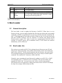
2. Pin-Out and Description
Pin
Name
Description
1
2
4
SD_MISO
SD_MOSI
VBAT
5
6
7
8
9
10
11
12
13
VDD 1.8V
RESET#
VSS
TRST#
TMS
TCK
X1
X2
UART_TX
SPI_DATARDY
I2C_DATARDY
14
15
16
17
18
19
20
UART_RX
SPI_BUSY
I2C_BUSY
TDI
TDO
VCC
I2C_SCL
VSS
RTXC1
21
22
23
24
25
I2C_SDA
SPI_SCK
SPI_MISO
SPI_MOSI
RTXC2
26
27
28
31
36
37
RTCK
DBGSEL
SPI_SSEL#
VSSA
CD_SSEL#
MISC
SD card signal
SD card signal
Power source for the internal RTC. Connect to 3V
battery or VCC. Always use 2 diodes to connect a
battery and VCC in case the battery runs out of power.
1.8V power source
uALFAT reset signal.
Ground
Do not connect
Do not connect
Do not connect
Pin 1 for 10 MHz oscillator
Pin 2 for 10 MHz oscillator
UART mode: Transmit pin of UART (output)
SPI and I2C modes: When high, it signals that
uALFAT wants to send some data and the host must
read it
Receive pin of UART (input)
SPI and I2C: When high, it signals that uALFAT is
being busy and not ready for new data.
Do not connect
Do not connect
3.3V power source
Clock pin for I2C
Ground
Pin 1 for 32.768 KHz oscillator. Optional for RTC with
backup battery.
Data pin for I2C
Clock pin for SPI
Master In Slave out for SPI (output)
Master Out Slave In for SPI (input)
Pin 2 for 32.768 KHz oscillator. Optional for RTC with
backup battery.
Do not connect
Do not connect
Slave Select for SPI (input)
Analog Ground
SD card signal
A miscellaneous pin. Functionality will be determined
in special releases
GHI Electronics, LLC.
5
User Manual
uALFAT™
File System Made Easy
Pin
Name
Description
42
43
44
VCC
VSS
SD_SCK
BL#
WAKE
3.3V Power source
Ground
SD card signal. This pin must be high when RESET# is
low. Also, when sending deep sleep command, a toggle
on this pin will wake up uALFAT
All pins that are not listed in the table above must be left unconnected. Always consult
uALFAT-SD schematics.
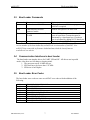
3. Boot Loader
3.1. General description
The boot loader is used to update the firmware of uALFAT. When there is a new
firmware release, you can simply download the file from our website and, using simple
commands, uALFAT can update itself. At power up uALFAT will send 2 characters ‘B’
and ‘L’ indicating that the boot loader is ready to load new file. To exit the boot loader
and start uALFAT firmware, send ‘R’ character. If uALFAT chip detects invalid
firmware then it returns ‘BL’ again. In such case, reprogramming uALFAT chip is
required. If uALFAT powers up in standalone mode, it will execute the firmware
immediately, no BL will be sent.
3.2. Boot Loader Use
The easiest way to update uALFAT is by placing the new firmware on any SD card
using any PC and a card reader. Once you have the firmware on the card, connect the
same card to uALFAT. The file must be placed in the root directory, not in any folder.
We recommend using newly formatted media. Now you are ready to send the update
command. The command is 3 characters, LOK (Load OK)
If needed, a user can update the new firmware by sending it over SPI, I2C or UART.
All commands return ‘!‘ followed by the error number. Also, the boot loader will
respond with ‘Wxx<CR>’ on every sector write, where xx is the sector number.
The firmware file is encrypted file. Loading an incorrect file on uALFAT can damage
the chip. Never tamper with the firmware files.
GHI Electronics, LLC.
6
User Manual
uALFAT™
File System Made Easy
3.3. Boot Loader Commands
Command
R
Use
Load and run uALFAT firmware
LOK
Load firmware file from
connected media
Write one sector to internal
FLASH
W
Notes
If Boot loader return BL then reprogramming
uALFAT is required
Returns !00 if pass or !xx error code
Follow ‘W’ by the sector number then 512
bytes of sector data. Transaction must be
terminated by a checksum byte. Checksum
byte is calculated by adding all 512 data bytes
V
Returns the loader version
Returned value is ASCII
Note: The boot loader is entirely separate program that loads uALFAT firmware. The
version number of the boot loader may not mach the version number of uALFAT. New
uALFAT chips come with no firmware loaded and must load the latest firmware
available on our website.
3.4. Communication Interfaces in boot Loader
The boot loader runs simpler drivers for UART, SPI and I2C. All drivers run in pooled
mode. Also, there are few things to keeping mind:
1. The processor runs at 10 MHz always.
2. SPI clock has to be lower than 1.25 MHz
3. SPI driver is half duplex.
3.5. Boot Loader Error Codes
The boot loader error codes are same as uALFAT error codes with the addition of the
following.
0xD1
0xD2
0xD3
0xD4
0xD7
0xD8
0xDA
0xDB
0xDE
GHI Electronics, LLC.
ERROR_FLAHS_NOT_BLANK
ERROR_VERIFY
ERROR_INTERNAL
ERROR_CHECKSUM
ERROR_INVALID_FRMWARE
ERROR_BR_COMMAND
ERROR_FILE_IS_EMPTY
ERROR_FILE_NOT_FOUND
ERROR_UNKNOWN_COMMAND
7
User Manual
uALFAT™
File System Made Easy
4. uALFAT™ Interfaces
uALFAT uses UART, I2C or SPI to communicate with any external microcontroller. At
power up, uALFAT samples SPI_SSEL# and SPI_SCK pins to determine what interface to
use. The following table describes the states
SPI_SSEL#
SPI_SCK
Interface
0
0
UART
0
1
Skip boot loader*
1
0
I2C
1
1
SPI
* Do not use.
4.1. UART Interface
In UART interface mode, UART_TX pin is used to send data to your microcontroller
and UART_RX pin to receive commands from your microcontroller. The default baud
rate for UART is 9600. Always use 8 bit with no parity and 1 stop bit. Baud rate is
changeable through BR command. CTS and RTS lines must be used to insure not loss
of data at high speeds. CTS pin is an input to uALFAT and when it is high uALFAT
will not send data and will wait for it to go low. CTS should be high as long as possible
to not slow down uALFAT. RTS pin is output from uALFAT and it is set high when
uALFAT FIFO is full. Depending on data transfer speed, RTS pin may never go high
because uALFAT is contentiously emptying the FIFO.
Note: The internal UART have a hardware TX FIFO that is 16 byte long. After
asserting CTS, uALFAT may still send the internal FIFO, up to 16 bytes.
Important: uALFAT will NOT send any data if CTS pin is high! If this pin is not
used then it must be connected to ground.
4.2. SPI Interface Mode
In SPI mode six pins are used for communication, to implement slave SPI. Two pins
are used for handshaking. SPI_SSEL, SPI_SCK, SPI_MISO, and SPI_MOSI are the
standard SPI pins where SSEL is used for Slave Select, SCK is the Serial Clock, MISO
is the data line going from uALFAT to your microcontroller, and MOSI is the data line
going from your microcontroller to uALFAT.
The Handshaking lines are SPI_DATARDY and SPI_BUSY. When uALFAT has data
to send to the PC, it raises DATARDY line. The host (SPI master) must read the data
from uALFAT as fast as possible. Data and commands can be sent to uALFAT at any
time except when SPI_BUSY is high.
GHI Electronics, LLC.
8
User Manual
uALFAT™
File System Made Easy
In the nature of SPI, the data flow is full duplex. On every SPI transaction, a data is
swapped between the master (your system) and the slave (uALFAT). This is great until
you need to read data from uALFAT but you don’t want to send a command. uALFAT
implements a software mechanism to handle this issue. Two special numbers are used to
handle the flow control. 0xFF and we will call it NDT (No Data Token) and 0xFE and
will call it HDT (Half Data Token)
Whenever uALFAT SPI sees NDT (again, it is 0xFF,) it will ignore it. This allows you
to read uALFAT without sending data. Of course you are sending NDT but it will be
ignored by uALFAT SPI driver.
This is everything you need to do if you are using numbers from 0 to 0xFD. Usually,
this is good in most cases as uALFAT commands are ASCII based and most users save
files as ASCII text. If you need to send 0xFF to uALFAT, you have to send HDT
followed by NDT. uALFAT will understand this as real 0xFF number and will not
ignore it. For 0xFE, you have to send HDT followed by HDT. Here is a simple example
in ‘C’ language on how your transmit routine should work:
SendData(char c)
{
if( (c==FF) || (c==0xFE) )
SendSPI(0xFE);
SendSPI(c);
}
If pooling is a preferred, it is possible to keep pooling uALFAT and not check
DATARDY pin at all. When there is no data, uALFAT will return NDT (0xFF)
Important: uALFAT requires the following in order for SPI to work:
• SCK is output from your system.
• SCK is idle High.
• SCK is slower than 8 MHz in full power mode and slower than 1.25 in rediced
power mode.
• Data is shifted out MSB first.
• Data is latched on the rising edge of SCK.
4.3. I2C Interface Mode
Four pins are needed for I2C communication. The USER_I2C_SCL and
USER_I2C_SDA are the two I2C bus lines. I2C_DATARDY and I2C_BUSY lines
work exactly the same way as SPI_DATARDY and SPI_BUSY work except the
interface is half duplex. When DATARDY is high, you can’t send data to uALFAT
until all the data is read and DATARDY is back low.
uALFAT runs in slave I2C mode always. The slave address of uALFAT is 0xA4. This
address is fixed and can’t be changed.
GHI Electronics, LLC.
9
User Manual
uALFAT™
File System Made Easy
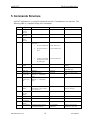
5. Commands Structure
uALFAT implements a very simple commands structure. Commands are one character. The
following table is a complete listing of the commands
CMD
Usage
Parameters
Example
Notes
A
Change
(access)
directory
Make new
directory
Erase an
empty
directory
Open File
Folder Name string
A MYFOLDER
Folder must exist
Folder Name string
M MYFOLDER
Folder must not exist
Folder Name string
E MYFOLDER
Folder must exist
filehandle Openmode>filename
Openmode :
1. R Open to Read only
O 0R>TEST.TXT
M
E
O
2.
W Open new file to
write.
O 1W>TEST2.TXT
3.
A Open to write data
starting from the end
of existing file.
O 3A>DATA.LOG
Close file
handle
Flush File
Filehande
C2
Filehandle
F1
D
W
Delete file
Filename
D test.txt
Writes data to
an open file
W B>4D
Must open file for write
first
R
Read data
from an open
file
Filehandl>datasize
Datasize (1 – FFFFFFFF)
bytes
FilehandleFiller>datasize
Datasize (1 – FFFFFFFF)
bytes
R 0Z>E8
Must open file for read first
P
Seek read file
pointer
P 0>FFA3
This function works on files
open for read only
@
Initialize the
file entry
pointer
Get next file
Filehande>newposition
newposition is a hex number
(0 - (filesize-1))
none
C
F
N
?
V
Q
Get File
Information
Version
number
Quick Format
GHI Electronics, LLC.
Always close when done
writing
Flush guarantees the data is
on the SD card.
@
none
Use @ command first
Filename
? file.txt
None
V
Confirming string which is:
CONFIRM FORMAT
Q CONFIRM
FORMAT
10
Memory cards must be
formatted on a PC first
User Manual
uALFAT™
File System Made Easy
CMD
Usage
Parameters
Example
Notes
B
Set baud rate
divider
Enable Echo
Divider value
B 1234
1 to enable and 0 to disable
#1
Media
Statistics
Sleep
None
K
F for full
R for reduced
H for hibernate
B for backup and S for shared
Read “UART Baud Rate”
section below
Always disable echo for
speed and when using SPI
and I2C
Can take a bit of time
depending on the media size
Read Power Modes section
for more details
TS
#
K
Z
T
S
Init time
DWORD hex Time&Date
structure †
X for hex Time&Date structure
and F for formatted
{
Set Time and
Date
Get current
Time and
Date
Read sector
}
Write sector
G
Not fully implemented yet
GF
Displays the current time
SectorNumber
{ 1234
SectorNumber
} 1234
Sector size is always 512
bytes
Use only if you know what
you are doing!!
** File Attributes are one byte Standard Attribute Structure in FAT system
File attributes:
ATTR_READ_ONLY
ATTR_HIDDEN
ATTR_SYSTEM
ATTR_VOLUME_ID
ATTR_DIRECTORY
ATTR_ARCHIVE
0x01
0x02
0x04
0x08
0x10
0x20
† Time & Date DWORD structure
struct FATtime
// 32 bits
{
WORD Second2:5;
// seconds divided by 2 (0..30)
WORD Minute:6;
// 0..59
WORD Hour:5;
// 0..23
WORD Day:5;
// 1..31
WORD Month:4;
// 1..12
WORD Year1980:7;
// Years since 1980
};
GHI Electronics, LLC.
11
User Manual
uALFAT™
File System Made Easy
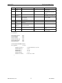
5.1. UART Baud Rate
uALFAT contains a fancy divider for baud rate. Using the divider we can set the
UART to almost any possible baud rate. Below is a table with some standard baud
rates. Note that the values do not work in boot loader. Always run boot loader at
default 9600 and after firmware execution, change the baud rate. The table contains
two sets of divider values, at 10 MHz and 70 MHz. Use the 70 MHz when run in full
power mode and the 10 MHz when running reduced power mode.
Baud Rate
9600
119200
38400
57600
115200
230400
460800
921600
Divider at 70 MHz
DCEF
6EEF
37EF
43F2
1EF4
0FF4
05A9
028B
Divider at 10 MHz
1FAB
0386
067C
08E5
04E5
02E5
01E5
Not possible!
For example: B 1EF4 will set the baud rate to 115200 when using full power mode.
uALFAT responds with !00 if command is accepted at the old baud rate and then it
changes the baud rate. You will then receive a second !00 at the new baud rate.
6. Getting Started
All commands are text based. User can use a terminal program to type in the commands
(if using a PC and RS323 level converter.) Also, any microcontroller can send
commands to write/read files/folders. NOTE: Each line is terminated by carriage return
only, to make parsing easier. If you use Hyper Terminal (or similar) program you have
to configure it to append LF to each CR. In Hyper terminal, you will find it at
“propertiesSettingsASCII SetupAppend Line Feed”
Important: uALFAT doesn’t echo back the data by default. Use ‘# 1’ command to
enable echo if needed.
At power up uALFAT will send BL (Read boot loader section for more details.)
Follow BL by ‘R’ and you should get the following. No carriage return is needed.
GHI Electronics, LLC
uALFAT(TM) 1.xx
GHI Electronics, LLC.
12
User Manual
uALFAT™
File System Made Easy
>
The > prompt means that uALFAT is ready to take commands
uALFAT can connect to two kinds of media types, SD and MMC cards.
To initialize the media, use the ‘I’ (initialize) command followed by carriage return.
uALFAT doesn’t detect card removal or replacement. The final application must
detect card removal. Also, uALFAT doesn’t check the protection switch on SD
cards. This means uALFAT will write on protected cards.
No harm will be caused to the card if removed as long as no files were open for write.
For step-by-step on how to use the commands, consult uALFAT Tutorial.
6.1. Directories (Folders)
Folders are fully supported by uALFAT. uALFAT doesn’t display what folder it is
accessing but it will keep track of the folders internally.
M UALFAT this command will create “UALFAT” folder
6.2. Files
Files can be opened for read, write or append. Opening a file for read requires that the
file exists on the media. Opening a file for write requires that the file doesn’t exist on
the media or it will be overwrited. Opening a file to append data to it will add data to a
file if it exists. If the file doesn’t exist then new file will be made.
With uALFAT you can open up to 4 files at the same time using file handles.
Keep in mind that all values here are ASCII based so when you need to send 0 to
uALFAT you will have to press 0 key on keyboard but when sending it through
external microcontroller you would have to end ASCII 0 which is 0x30
hexadecimal.
When sending data to the opened file, data can be anything, ASCII or binary!
Handles are used for fast access to a file. If a user needs to log data to 2 files at the same
time, “VOLTAGE.LOG” and “CURRENT.LOG” file handles become very use full.
GHI Electronics, LLC.
13
User Manual
uALFAT™
File System Made Easy
To do so, open VOLTAGE.LOG under handle 1 and CURRENT.LOG under handle
2. Now start sending your data to handle 1 and 2 instead to the file name.
To open a file use,
O 1W VOLTAGE.LOG
The previous command will create new file at the current directory with name
“VOLTAGE.LOG” and the file handle is 1. Now to save data to that file use
W 1>10
Now the “W” will write data to a file that is open at handle 1 and will write 16
bytes (10 hexadecimal = 16 decimal) to it. After sending carriage return (enter,)
uALFAT will return !00. This indicates that uALFAT is ready for your data. Now,
start sending your 16 byte of data. When 16 bytes are sent, uALFAT will return
another error code.
Note: All numbers given to uALFAT commands are hexadecimal numbers.
This is an example session:
>M LOG_DATA
!00
>A LOG_DATA
!00
>O 1W>VOLTAGE.LOG
!00
>O 2W>CURRENT.LOG
!00
>W 1>7
!00
12.123V
!00
>W 7>A
!00
1234567890
!00
W 1>7
!00
10.194V
!00
>
create new directory
change directory
create new file for write inside LOG_DATA folder
create new file for write inside LOG_DATA folder
command to write 7 bytes (characters) to file at handle 1
uALFAT accepted the write command
enter the data to go to the file
data written successfully
writes 10 bytes to file at handle 7
uALFAT accepted the write command
enter your data
data written successfully
add 7 bytes(characters) to file at handle 1
uALFAT accepted the write command
enter the data to go to the file
data written successfully
uALFAT is ready for more commands.
Note1: file names must not contain its path (i.e. “\sub1\file.txt”). Only pure names
are allowed (i.e. “file.txt”).
Note2: Folders and files use naming convention that is same of DOS naming
convention. Names must be 8 characters or less and 3 characters or less for the
extension and they must be upper case. All upper case letters, numbers and
underscore’_’ can be used for names and extensions.
Example
“DATA.LOG”, “NOEXT”, “FOLDER”, “FOLDER.123”,
“NO_SPACE.TXT”, “12345678.123”
GHI Electronics, LLC.
14
User Manual
uALFAT™
File System Made Easy
If an error occurred, uALFAT returns the symbol ‘!’ followed by the error
number.
GHI Electronics, LLC.
15
User Manual
uALFAT™
File System Made Easy
7. uALFAT™ Error Codes
All Commands return with prompt or with error codes.
Error Number
0x00
0x01
0x02
0x03
0x11
0x12
0x13
0x14
0x21
0x22
0x23
0x24
0x25
0x31
0x32
0x33
0x34
0x35
0x40
0x41
0x42
0x43
0x44
0x45
0x46
0x47
0x48
0x49
0x4A
0x4B
0x4C
0x4D
0x4E
0x4F
0x61
0x62
0x63
0x64
0x65
0x66
0x67
0x68
0xFD
GHI Electronics, LLC.
Description
No Error
ERROR_READ_SECTOR
ERROR_WRITE_SECTOR
ERROR_ERASE_SECTOR
ERROR_MBR_SIGNATURE_MISSMATCH
ERROR_BS_SIGNATURE_MISSMATCH
ERROR_SECTOR_SIZE_NOT_512
ERROR_FSINFO_SIGNATURE_MISSMATCH
ERROR_CLUSTER_OVER_RANGE
ERROR_CLUSTER_UNDER_RANGE
ERROR_NEXT_CLUSTER_VALUE_OVER_RANGE
ERROR_NEXT_CLUSTER_VALUE_UNDER_RANGE
ERROR_NO_FREE_CLUSTERS
ERROR_FILE_NAME_FORBIDDEN_CHAR
ERROR_FILE_NAME_DIR_NAME_OVER_8
ERROR_FILE_NAME_DIR_EXTENSION_OVER_3
ERROR_FILE_NAME_FIRST_CHAR_ZERO
ERROR_MEDIA_FULL
DIR_ENT_FOUND
DIR_ENT_NOT_FOUND
ERROR_FOLDER_IS_CORRUPTED_FIRST_CLUSTER
ERROR_FOLDER_IS_CORRUPTED_DIR_DOT_NOT_FOUND
ERROR_FOLDER_IS_CORRUPTED_DIR_DOTDOT_NOT_FOUND
ERROR_ROOT_DIRECTORY_IS_FULL
ERROR_OPEN_FOLDER_FILE
ERROR_WRTIE_TO_READ_MODE_FILE
ERROR_SEEK_REQUIER_READ_MODE
ERROR_INVALID_SEEK_POINTER
ERROR_FOLDER_NOT_EMPTY
ERROR_IS_NOT_FOLDER
ERROR_READ_MODE_REQUIRED
ERROR_END_OF_DIR_LIST
ERROR_FILE_PARAMETERS
ERROR_INVALID_HANDLE
ERROR_COMMANDER_BAD_COMMAND
ERROR_COMMANDER_STR_LEN_TOO_LONG
ERROR_COMMANDER_NAME_NOT_VALID
ERROR_COMMANDER_NUMBER_INVALID
ERROR_COMMANDER_WRITE_PARTIAL_FAILURE
ERROR_COMMANDER_UNKNOWN_MEDIA_LETTER
ERROR_COMMANDER_FAILED_TO_OPEN_MEDIA
ERROR_COMMANDER_INCORRECT_CMD_PARAMETER
ERROR_COMMANDER_UNKNOWN_ERROR
16
User Manual
uALFAT™
File System Made Easy
8. Power Modes
In some applications power consumption is very critical. uALFAT is designed with low
power in mind. Although you can completely shut off uALFAT’s power for zero power
consumption, some user may prefer to put uALFAT to sleep instead of power off to
keep the file handles open. Also, uALFAT can run at 2 different speeds.
uALFAT oscillator is 10 MHz. When executing the boot loader or the firmware,
uALFAT runs in reduced power mode. In this mode, uALFAT draws about 8mA
including 1.8V regulator.
If high performance is required, you can run uALFAT at full power where the core runs
at 70 MHz. In this mode, the complete uALFAT-SD board draws about 38mA.
Hibernation is also another option. If the system doesn’t need and file operations,
uALFAT can hibernate and the core draws about 10uA. Keep in mind that regulators
have their own current draw and a minimum draw. uALFAT-SD board draws 1mA
when in hibernate.
The command to change the power mode is ‘Z’. When changing the clock speed, you
have to keep many things in mind. For example, the SPI clock can be the system clock
divided by 8 maximum. So if the system is in reduced power mode running at 10 MHz,
the SPI SCK can be 1.25 MHz maximum. Also, the UART baud rate needs to be
adjusted to hold the correct divider value. Look at “UART Baud Rate” section for more
details on the divider values.
Z F>DCEF
switch to run at 70 MHz and set the UART baud rate to 9600.
Z R>1FAB
set the system to run at 10 MHz and baud rate of 9600
Now, what if we are using SPI or I2C interfaces? Even in this case you are required to
set the UART divider and you can use any one of the values.
When uALFAT goes in hibernation mode, it can be woken up by toggling the WAKE
pin. This in is multi purpose and must always be left disconnected from your system
except when there is a need to wake uALFAT. This can be accomplished by setting the
pin of your micro that connects to WAKE to be input. When there is a need to wake
uALFAT, set your pin to low then make the pin output, wit for few micro seconds and
then set the pin back to input.
GHI Electronics, LLC.
17
User Manual
uALFAT™
File System Made Easy
9. Power and Oscillator
uALFAT is very simple to add to your new or existing designs, it requires very few
components. Two voltages are needed; 3.3V and 1.8V, crystal and very few RCs, Check
the pin description and schematics for more details. You can also find more details on
the chipset base (LPC2103) data sheet on Philips website
www.semiconductors.philips.com and the schematics of uALFAT-SD on our website
www.ghielectronics.com
10. Special Firmware
uALFAT’s standard firmware contains many features to suite any application. If your
application requires a special need, we can implement a special firmware to suite your
needs. Loading the updated firmware or special firmware is extremely easy. Look at the
boot loader section.
Cost for special firmware is fairly low. We charge $60/h with a minimum of 25 hours.
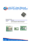
11. Development and OEM Circuit Boards
uALFAT-SD is our uALFAT chip on a small size board. The low cost and the ease of
use make uALFAT-SD the ultimate solution for OEMs or hobbyists. The SD/MMC
media connector is placed on one side of the board, making it possible to mount the
uALFAT-SD board inside your product case using 90 degree brackets. The full
schematic and board layout is on our website www.ghielectronics.com.
uALFAT-SD board contains 1.8 V regulator onboard. You will only need 3.3V for
power. The pin out of the board gives you access to SD card detect and pins to all
uALFAT’s signals.
We are also capable of designing special boards to fit your needs.
GHI Electronics, LLC.
18
User Manual
uALFAT™
File System Made Easy
12. Licensing
Each uALFAT chip comes with unconditional license of use from GHI Electronics,
LLC. There are many patented technologies utilized in uALFAT that must be account
for.
•
The SD card is used in MMC compatibility mode; therefore, no license is required
from the SD organization.
•
FAT file system is a patent of Microsoft Corporation. Licensing fee for using FAT
file system must be paid by companies who wish to use FAT file system in their
products. For more information, visit Microsoft’s website.
http://www.microsoft.com/mscorp/ip/tech/fat.asp
GHI Electronics, LLC provides a technology that allows users to read and write raw
sectors and read and write FAT files. If FAT functions are used by uALFAT users
then they must contact Microsoft for licensing. GHI Electronics, LLC should be
liable for any unpaid licenses.
Copyright GHI Electronics, LLC. Trademarks are owned by their respective companies.
ALFAT, µALFAT, ALFATxp, USBizi and USBwiz are trademarks of GHI Electronics, LLC
………………… DISCLAIMER …………………
IN NO EVENT SHALL GHI ELECTRONICS, LLC. OR ITS CONTRIBUTORS BE LIABLE FOR ANY DIRECT, INDIRECT,
INCIDENTAL, SPECIAL, EXEMPLARY, OR CONSEQUENTIAL DAMAGES (INCLUDING, BUT NOT LIMITED TO,
PROCUREMENT OF SUBSTITUTE GOODS OR SERVICES; LOSS OF USE, DATA, OR PROFITS; OR BUSINESS
INTERRUPTION) HOWEVER CAUSED AND ON ANY THEORY OF LIABILITY, WHETHER IN CONTRACT, STRICT IABILITY,
OR TORT (INCLUDING NEGLIGENCE OR OTHERWISE) ARISING IN ANY WAY OUT OF THE USE OF THIS SOFTWARE,
EVEN IF ADVISED OF THE POSSIBILITY OF SUCH DAMAGE.
COMPANIES, WHO UNITIZE uALFAT OR USBwiz IN THEIR PRODUCTS, MUST CONTACT MICROSOFT CORPORATION
FOR FAT FILE SYSTEM LICENCING. GHI ELECTRONICS, LLC SHALL NOT BE LIABLE FOR UNPAID LICENSE(S).
SPECIFICATONS ARE SUBJECT TO CHANGE WITHOUT ANY NOTICE.
GHI Electronics, LLC.
19
User Manual