
1
» User’s Guide «
KBox C-101
User’s Guide (Version 2.00)
1055-6575
www.kontron.com
This page is intentionally left blank.
www.kontron.com
1. Table of Contents
KBox C-101 – User’s Guide (Version 2.00)
1. Table of Contents
1. Table of Contents ..................................................................................................................................... 1
1.1. Table of Figures...................................................................................................................................... 4
2. Introduction ........................................................................................................................................... 6
2.1. Symbols used in this Manual..................................................................................................................... 7
3. Important Instructions............................................................................................................................. 8
3.1. Obligation of Diligence............................................................................................................................ 8
3.2. Personnel ............................................................................................................................................. 8
3.3. Appropriate Use, Field of Application ......................................................................................................... 8
3.4. Warranty Note ....................................................................................................................................... 8
3.5. Exclusion of Accident Liability Obligation.................................................................................................... 8
3.6. Liability Limitation / Exemption from the Warranty Obligation ........................................................................ 8
4. General Safety Instructions for IT Equipment............................................................................................... 9
4.1. Electrostatic Discharge (ESD) ..................................................................................................................10
4.1.1. Grounding Methods.........................................................................................................................10
5. Electromagnetic Compatibility (Class B Device) ..........................................................................................11
5.1. Electromagnetic Compatibility (EU) ..........................................................................................................11
5.2. FCC Statement (USA)..............................................................................................................................11
5.3. EMC-Compliance (Canada) ......................................................................................................................11
6. Shipment and Unpacking .........................................................................................................................12
6.1. Unpacking ...........................................................................................................................................12
6.2. Scope of Delivery...................................................................................................................................12
6.2.1. Standard.......................................................................................................................................12
6.2.2. Optional Parts ................................................................................................................................12
6.2.3. Optional System Extension ...............................................................................................................12
6.3. Spare Parts ..........................................................................................................................................12
6.4. Type Label and Product Identification .......................................................................................................13
7. System Overview.....................................................................................................................................14
7.1. RTC .....................................................................................................................................................15
7.1.1. RTC Buffer Time ..............................................................................................................................15
7.1.2. Setting the RTC...............................................................................................................................16
7.2. System Expansion Capabilities .................................................................................................................16
7.2.1. Mini PCI Express® Interfaces.............................................................................................................16
7.2.2. Standard PCI Express® Interfaces ......................................................................................................16
7.2.3. SATA Interfaces ..............................................................................................................................16
7.2.4. mSATA (MO-300) ............................................................................................................................16
7.3. Front Side ............................................................................................................................................18
7.3.1. X101 - Power Input Connector ...........................................................................................................20
7.3.2. X102/X103/X104 - Ethernet Connectors (ETH) .....................................................................................20
7.3.3. X105/X106 - USB 3.0.......................................................................................................................20
7.3.4. X107/X108 - USB 2.0.......................................................................................................................20
7.3.5. X109 - DisplayPort ..........................................................................................................................20
7.3.6. SDCARD Slot ..................................................................................................................................21
7.3.7. X110 - RS232 .................................................................................................................................21
www.kontron.com
1
1. Table of Contents
KBox C-101 – User’s Guide (Version 2.00)
7.3.8. POWER Button and PWR LED ............................................................................................................. 22
7.3.9. RESCUE Button and RSQ LED ............................................................................................................. 22
7.3.10. Status and General Purpose LEDs ..................................................................................................... 23
7.3.11. X205 - Optional FIELDBUS Interface ................................................................................................. 23
7.3.12. PCIe Expansion Slots 1 and 2 .......................................................................................................... 23
7.3.13. SATA Drive Bays............................................................................................................................ 24
7.4. Left and Right Side View......................................................................................................................... 25
7.5. Top and Bottom Side View ...................................................................................................................... 25
7.6. Rear Side View...................................................................................................................................... 26
7.6.1. Functional Earth Stud ..................................................................................................................... 26
7.7. Internal View ....................................................................................................................................... 27
7.7.1. Integrated COMe Module ................................................................................................................. 28
7.7.2. mSATA Socket................................................................................................................................ 28
7.7.3. Expansion Slots for PCIe Mini Cards.................................................................................................... 29
7.7.4. Expansion Slots for PCIe x4 Cards ...................................................................................................... 29
8. Thermal Considerations........................................................................................................................... 30
8.1. Available Processors.............................................................................................................................. 30
8.2. Convection Cooling ............................................................................................................................... 30
8.3. Active Cooling via the optional Fan Tray .................................................................................................... 30
8.4. Minimum System Clearance..................................................................................................................... 30
8.5. Maximum Temperatures ......................................................................................................................... 30
8.6. Third Party Components ......................................................................................................................... 31
8.7. Processor Thermal Monitoring ................................................................................................................. 31
8.8. Processor Thermal Trip Feature ................................................................................................................ 31
9. Installation Instructions......................................................................................................................... 32
9.1. Instructions for Control Cabinet Mount Installation..................................................................................... 32
10. Accessing Internal Components.............................................................................................................. 33
10.1. Top Cover .......................................................................................................................................... 34
10.2. Opening and Closing the KBox C-101 ...................................................................................................... 35
10.2.1. Installing/Removing the PCIe Expansion Cards................................................................................... 37
10.2.2. Installing/Removing the PCIe Mini Card ............................................................................................ 37
10.2.3. Installing an mSATA SSD ................................................................................................................ 38
11. Control Cabinet Mounting...................................................................................................................... 39
11.1. DC Power Connection ........................................................................................................................... 40
11.1.1. Cabling....................................................................................................................................... 40
12. Starting Up.......................................................................................................................................... 41
12.1. Connecting to DC Main Power Supply....................................................................................................... 41
12.2. Power OFF/ON Procedure ...................................................................................................................... 42
12.3. Operating System and Hardware Component Drivers .................................................................................. 43
13. Maintenance and Cleaning ..................................................................................................................... 44
14. System Extensions................................................................................................................................ 45
14.1. Serial Port RS232/RS422 ...................................................................................................................... 46
14.2. CAN Port............................................................................................................................................ 46
14.3. DVI-D Interface Connector .................................................................................................................... 46
14.4. UPS Battery (Uninterruptable Power Supply) TBD ...................................................................................... 46
14.5. Optional KBox C-101 Version with Fan Tray............................................................................................... 47
2
www.kontron.com
1. Table of Contents
KBox C-101 – User’s Guide (Version 2.00)
14.6. Fan Tray .............................................................................................................................................48
14.6.1. Replacing the Fan Tray ...................................................................................................................48
14.6.2. Cleaning the Air Filter ....................................................................................................................49
15. uEFI BIOS.............................................................................................................................................51
15.1. uEFI Shell Introduction, Basic Operation..................................................................................................51
15.1.1. Entering the uEFI Shell...................................................................................................................51
15.1.2. Exiting the uEFI Shell.....................................................................................................................51
15.1.3. Kontron-Specific uEFI Shell Commands .............................................................................................52
15.2. uEFI Shell Scripting..............................................................................................................................52
15.2.1. Startup Scripting ..........................................................................................................................52
15.2.2. Create a Startup Script ...................................................................................................................53
15.2.3. Examples of Startup Scripts.............................................................................................................53
15.3. Updating the uEFI BIOS ........................................................................................................................54
15.3.1. uEFI BIOS Recovery .......................................................................................................................54
15.3.2. Determining the Active Flash...........................................................................................................54
16. Technical Specification ..........................................................................................................................55
16.1. Mechanical Specifications of the KBox C-101.............................................................................................56
16.2. Mechanical Specifications of the KBox C-101 with Fan Tray Option ................................................................57
16.3. Environmental Specifications.................................................................................................................58
16.4. CE-Directives and Standards ..................................................................................................................59
17. KBox C-101 CPLD Specific Registers.........................................................................................................60
17.1. Reset Status Register (RSTAT) ................................................................................................................60
17.2. Interrupt Status Register (INTSTAT) ........................................................................................................61
17.3. Shutdown Control Register (SHDN_CTRL) .................................................................................................61
17.4. SPI Flash Control Registers (SPIFCTRL).....................................................................................................62
17.5. LED Control / Status Register (LCTRLSR)...................................................................................................62
18. Standard Interfaces – Pin Assignments....................................................................................................63
18.1.1. (X 101) Power Input Connector........................................................................................................63
18.1.2. (X 110) Serial Interface RS232.........................................................................................................63
18.1.3. DisplayPort ..................................................................................................................................64
18.1.4. (X 107, X 108) USB 2.0 Port ............................................................................................................64
18.1.5. (X 105, X 105) USB3.0 Port .............................................................................................................64
18.1.6. (X 102, X 103, X 104) Ethernet Connectors.........................................................................................65
18.2. Optional Interfaces via Adapter Modules ..................................................................................................66
18.2.1. DVI-D (Single Link)........................................................................................................................66
18.2.2. Serial Port RS232/RS422 ................................................................................................................67
18.2.3. CAN Bus Port ................................................................................................................................68
18.2.4. UPS Connector (TBD) .....................................................................................................................68
19. Technical Support .................................................................................................................................69
19.1. Returning Defective Merchandise............................................................................................................69
www.kontron.com
3
1. Table of Contents
KBox C-101 – User’s Guide (Version 2.00)
1.1. Table of Figures
Fig. 1: Type label.........................................................................................................................................13
Fig. 2: RTC buffer time depending on temperature .............................................................................................15
Fig. 3: Bottom side view ...............................................................................................................................17
Fig. 4: Right side view ..................................................................................................................................17
Fig. 5: Front side view config. with removable drives..........................................................................................17
Fig. 6: Front side view config. without removable drives .....................................................................................17
Fig. 7: Left side view ....................................................................................................................................17
Fig. 8: Top side view ....................................................................................................................................17
Fig. 9: Rear side view ...................................................................................................................................17
Fig. 10: KBox C-101 - front view (shown with removable drive bays) .....................................................................18
Fig. 11: Block Diagram - KBox C-101 ...............................................................................................................19
Fig. 12: X101 - 24VDC power input connector ...................................................................................................20
Fig. 13: SDCARD slot ....................................................................................................................................21
Fig. 14: SD card (not included) ......................................................................................................................21
Fig. 15:Detail - Power button and PWR LED/Rescue button and RSQ LED ................................................................22
Fig. 16: Detail - Status and General Purpose LEDs ..............................................................................................23
Fig. 17: X205 - Optional FIELDBUS interface .....................................................................................................23
Fig. 18: PCIe 1 and PCIe 2 slots ......................................................................................................................23
Fig. 19: Drive 1 and Drive 2 for removable 2.5" SATA HDD/SSD (option); closed drive bays........................................24
Fig. 20: Drive bay 1 with opened drive bay cover ...............................................................................................24
Fig. 21: Inserting/removing a 2.5" removable SSD ............................................................................................24
Fig. 22: Right side of the KBox C-101 system ....................................................................................................25
Fig. 23: Left side of the KBox C-101 system ......................................................................................................25
Fig. 24:Top side of the KBox C-101 system .......................................................................................................25
Fig. 25: Bottom side of the KBox C-101 system .................................................................................................25
Fig. 26: Rear side of the KBox C-101 system .....................................................................................................26
Fig. 27: KBox C-101 - internal view .................................................................................................................27
Fig. 28: KBox C-101 - internal view with COM Express module ..............................................................................28
Fig. 29: Inside of the top cover with fixing brackets ...........................................................................................34
Fig. 30: This movment allow you to remove the centring and fixing bracket of the top cover (detail of the KBox C-101) ..35
Fig. 31: Removing the cover (detail of the KBox C-101) ......................................................................................35
Fig. 32: KBox C-101 without top cover - removing the rihgt side cover...................................................................36
Fig. 33: KBox C-101 without top and right side cover .........................................................................................36
Fig. 34: Detail inside of the KBox C-101 with PCIe Riser card for 2x PCIe x4 slots......................................................37
4
www.kontron.com
1. Table of Contents
KBox C-101 – User’s Guide (Version 2.00)
Fig. 35: Keep out area for mounting around KBox C-101 (front side view).............................................................. 39
Fig. 36: Phoenix power plug terminal ............................................................................................................. 40
Fig. 37: KBox C-101 with removable drive bays and optional interfaces ................................................................. 45
Fig. 38: KBox C-101 with optional interfaces and without removable drive bays and ................................................ 45
Fig. 39: KBox C-101 equipped with the optional fan tray .................................................................................... 47
Fig. 40: Fan tray of the KBox C-101 (cable connection between fan and fan connector are included in this assembly).... 48
Fig. 41: Detail KBox C-101 with fan tray extension: air filter holder on the bottom side ............................................ 49
Fig. 42: KBox c-101 with removed fan tray and removed air filter ......................................................................... 50
Fig. 43: Holder without air filter .................................................................................................................... 50
Fig. 44: Holder with air filter......................................................................................................................... 50
Fig. 45: Air filter......................................................................................................................................... 50
Fig. 46:Dimensions: right side ...................................................................................................................... 56
Fig. 47: Dimensions: front side with key holes .................................................................................................. 56
Fig. 48:Dimensions: detail key hole................................................................................................................ 56
Fig. 49: Dimensions: top side........................................................................................................................ 56
Fig. 50:Dimensions: right side (with fan tray option)......................................................................................... 57
Fig. 51: Dimensions: front side with key holes (with fan tray option) .................................................................... 57
Fig. 52:Dimensions: detail key hole................................................................................................................ 57
Fig. 53: Dimensions: top side (with fan trayoption)........................................................................................... 57
www.kontron.com
5
2. Introduction
KBox C-101 – User’s Guide (Version 2.00)
2. Introduction
Kontron would like to point out that the information contained in this manual may be subject to technical alteration,
particularly as a result of the constant upgrading of Kontron products. The attached documentation does not entail any
guarantee on the part of Kontron with respect to technical processes described in the manual or any product
characteristics set out in the manual. Kontron does not accept any liability for any printing errors or other inaccuracies in
the manual unless it can be proven that Kontron is aware of such errors or inaccuracies or that Kontron is unaware of
these as a result of gross negligence and Kontron has failed to eliminate these errors or inaccuracies for this reason.
Kontron expressly informs the user that this manual only contains a general description of technical processes and
instructions which may not be applicable in every individual case. In cases of doubt, please contact Kontron.
This manual is protected by copyright. All rights are reserved by Kontron. Copies of all or part of this manual or
translations into a different language may only be made with the prior written consent of Kontron. Kontron points out
that the information contained in this manual is constantly being updated in line with the technical alterations and
improvements made by Kontron to the products and thus this manual only reflects the technical status of the products by
Kontron at the time of printing.
© 2014 by Kontron Europe
Printing and duplication, even of sections, is only permissible with the express approval of
Kontron Europe GmbH
Lise-Meitner-Str. 3-5
86156 Augsburg
Germany
6
www.kontron.com
2. Introduction
KBox C-101 – User’s Guide (Version 2.00)
2.1. Symbols used in this Manual
Symbol
Meaning
This symbol indicates the danger of injury to the user or the risk of damage to the product if the
corresponding warning notices are not observed.
This symbol indicates that the product or parts thereof may be damaged if the corresponding warning
notices are not observed.
This symbol indicates general information about the product and the user manual.
This symbol indicates detail information about the specific product configuration.
This symbol precedes helpful hints and tips for daily use.
www.kontron.com
7
3. Important Instructions
KBox C-101 – User’s Guide (Version 2.00)
3. Important Instructions
Prior performing any installation or commissioning work with the device, this manual must be read carefully to become
familiar with the device. The general safety instructions and information apply to all Kontron equipment for industrial
control applications.
This manual provides important information required for the proper operation of the KBox C-101!
This chapter contains instructions which must be observed when working with the KBox C-101.
3.1. Obligation of Diligence
The operator must ensure that industrial PCs of the KBox Series are only used in control cabinet environments, the
operation manual is understood and the personnel has the necessary authorization and regularly training about relevant
standards, regulations and instructions.
Further the operator must ensure that the industrial PC is mounted, operated and maintained according to the instruction
of this manual.
Depending on the target application the operator must observe the current applicable national and international
regulations and standards.
3.2. Personnel
Only personnel with appropriate qualifications, trainings and authorization are permitted to install and work with the
Kontron KBox C-101 industrial PC.
All applicable technical standards, regulations and guidelines for the installation and usage of the device must be
understood and followed. Further accident prevention regulations and directives must be observed.
Every user of this system must be familiar with the instructions described in this manual.
3.3. Appropriate Use, Field of Application
The KBox C-101 is to be used in control cabinet applications only. Necessary fire enclosures and similar safety measures
are to be provided by the control cabinet. The operator must ensure that the place of installation complies with applicable
national and international standards and regulations.
3.4. Warranty Note
Due to their limited service life, parts which by their nature are subject to a particularly high degree of wear (wearing
parts) are excluded from the warranty beyond that provided by law. This applies e.g., to buffer battery storage media like
SD cards.
3.5. Exclusion of Accident Liability Obligation
Kontron shall be exempted from the statutory accident liability obligation if the user fails to observe the included
document: “General Safety Instructions for IT Equipment” the hints in this manual or eventually the warning signs label
on the device.
3.6. Liability Limitation / Exemption from the Warranty Obligation
In the event of damage to the device caused by failure to observe the included document “General Safety Instructions for
IT Equipment” in this manual or eventually the warning signs label on the device, Kontron shall not be required to honor
the warranty even during the warranty period and shall be exempted from the statutory accident liability obligation.
8
www.kontron.com
4. General Safety Instructions for IT Equipment
KBox C-101 – User’s Guide (Version 2.00)
4. General Safety Instructions for IT Equipment
Please read this chapter carefully and take careful note of the instructions, which have been compiled for
your safety and to ensure to apply in accordance with intended regulations. If the following general
safety instructions are not observed, it could lead to injuries to the operator and/or damage of the
product; in cases of nonobservance of the instructions Kontron is exempt from accident liability, this
also applies during the warranty period.
The product has been built and tested according to the basic safety requirements for low voltage (LVD) applications and
has left the manufacturer in safety-related, flawless condition. To maintain this condition and to also ensure safe
operation, the operator must not only observe the correct operating conditions for the product but also the following
general safety instructions:
❏ The product must be used as specified in the product documentation, in which the instructions for safety for the
product and for the operator are described. These contain guidelines for setting up, installation and assembly,
maintenance, transport or storage.
❏ The on-site electrical installation must meet the requirements of the country's specific local regulations.
❏ If a power cable comes with the product, only this cable should be used. Do not use an extension cable to connect the
product.
❏ To guarantee that sufficient air circulation is available to cool the product, please ensure that the ventilation
openings are not covered or blocked. If an air filter is provided, this should be cleaned regularly. Do not place the
system close to heat sources or damp places. Make sure the system is well ventilated.
❏ Only devices or parts which fulfill the requirements of SELV circuits (Safety Extra Low Voltage) as stipulated by
IEC 60950-1 may be connected to the available interfaces.
❏ Before opening the device, make sure that the device is disconnected from the mains.
❏ Switching off the device by its power button does not disconnect it from the mains. Complete disconnection is only
possible if the power cable is removed from the wall plug or from the device. Ensure that there is free and easy access
to enable disconnection.
❏ The device may only be opened for the insertion or removal of add-on cards (depending on the configuration of the
system). This may only be carried out by qualified operators.
❏ If extensions are being carried out, the following must be observed:
• all effective legal regulations and all technical data are adhered to
• the power consumption of any add-on card does not exceed the specified limitations
• the current consumption of the system does not exceed the value stated on the product label.
❏ Only original accessories that have been approved by Kontron can be used.
❏ Please note: safe operation is no longer possible when any of the following applies:
• the device has visible damages or
• the device is no longer functioning
In this case the device must be switched off and it must be ensured that the device can no longer be operated.
www.kontron.com
9
4. General Safety Instructions for IT Equipment
KBox C-101 – User’s Guide (Version 2.00)
Additional safety instructions for DC power supply circuits
❏ To guarantee safe operation of devices with DC power supply voltages larger than 60 volts DC or a power consumption
larger than 240 VA, please observe that:
• the device is set up, installed and operated in a room or enclosure marked with “RESTRICTED ACCESS”, if there are no
safety messages on product as safety signs and labels on the device itself.
• no cables or parts without insulation in electrical circuits with dangerous voltage or power should be touched
directly or indirectly
• a reliable protective earthing connection is provided
• a suitable, easily accessible disconnecting device is used in the application (e.g. overcurrent protective device,), if
the device itself is not disconnectable
• a disconnect device, if provided in or as part of the equipment, shall disconnect both poles simultaneously
• interconnecting power circuits of different devices cause no electrical hazards
❏ A sufficient dimensioning of the power cable wires must be selected – according to the maximum electrical
specifications on the product label – as stipulated by EN60950-1 or VDE0100 or EN60204 or UL508 regulations.
❏ The devices do not generally fulfill the requirements for "centralized DC power systems“ (UL 60950-1, Annex NAB; D2)
and therefore may not be connected to such devices!
4.1. Electrostatic Discharge (ESD)
A sudden discharge of electrostatic electricity can destroy static-sensitive devices or micro-circuitry. Proper packaging
and grounding techniques are necessary precautions to prevent damage. Always take the following precautions:
1. Transport boards in static-safe containers such as boxes or bags.
2. Keep electrostatic sensitive parts in their containers until they arrive at the ESD-safe workplace.
3. Always be properly grounded when touching a sensitive board, component, or assembly.
4. Store electrostatic-sensitive boards in protective packaging or on antistatic mats.
4.1.1. Grounding Methods
The following measures help to avoid electrostatic damages to the device:
1. Cover workstations with approved antistatic material. Always wear a wrist strap connected to workplace as well as
properly grounded tools and equipment.
2. Use anti-static mats, heel straps, or air ionizes to give added protection.
3. Always handle electrostatic sensitive components by their edge or by their casing.
4. Avoid contact with pins, leads, or circuitry.
5. Turn off power and input signals before inserting and removing connectors or connecting test equipment.
6. Keep work area free of non-conductive materials such as ordinary plastic assembly aids and styrofoam.
7. Use field service tools such as cutters, screwdrivers, and vacuum cleaners which are conductive.
8. Always place drives and boards PCB-assembly-side down on the foam.
10
www.kontron.com
5. Electromagnetic Compatibility (Class B Device)
KBox C-101 – User’s Guide (Version 2.00)
5. Electromagnetic Compatibility (Class B Device)
5.1. Electromagnetic Compatibility (EU)
This product complies with the European Council Directive on the approximation of the laws of the member states relating
to electromagnetic compatibility (2004/108/EC), Class B limits for Information Technology Equipment according to
European Standard EN 55022.
5.2. FCC Statement (USA)
This equipment has been tested and found to comply with the limits for a Class B digital device, pursuant to Part 15 of the
FCC Rules. These limits are designed to provide reasonable protection against harmful interference in a residential
installation. This equipment generates, uses and can radiate radio frequency energy and, if not installed and used in
accordance with the instructions, may cause harmful interference to radio communications. However, there is no
guarantee that interference will not occur in a particular installation.
If this equipment does cause harmful interference to radio or television reception, which can be determined by turning
the equipment off and on, the user is encouraged to try to correct the interference by one or more of the following
measures:
❏ Reorient or relocate the receiving antenna.
❏ Increase the separation between the equipment and receiver.
❏ Connect the equipment into an outlet on a circuit different from that to which the receiver is connected.
❏ Consult the dealer or an experienced radio/TV technician for help.
5.3. EMC-Compliance (Canada)
The method of compliance is self-declaration to Canadian ICES-003:
(English): This Class B digital apparatus complies with the Canadian ICES-003.
(French) : Cet appareil numérique de la class B est conforme à la norme NMB-003 du Canada.
www.kontron.com
11
6. Shipment and Unpacking
KBox C-101 – User’s Guide (Version 2.00)
6. Shipment and Unpacking
6.1. Unpacking
Proceed as follows to unpack the unit:
1. Remove packaging.
2. Do not discard the original packaging. Keep it for future relocation.
3. Check the delivery for completeness by comparing it with your order.
4. Please keep the associated paperwork. It contains important information for handling the unit.
5. Check the contents for visible shipping damage.
6. If you notice any shipping damage or inconsistencies between the contents and your order, please contact Kontron
for help and information.
6.2. Scope of Delivery
6.2.1. Standard
KBox C-101 (corresponding to the ordered system configuration)
POWER-SUBCON PSC 1,5/ 3-F, 3-pin plug
General Safety Instructions for IT Equipment
6.2.2. Optional Parts
Front accessible drive bays for 2.5" HDD/SSDs
Mini-PCIe cards
mSATA cards (MO-300)
PCIe cards
6.2.3. Optional System Extension
RS232/RS422 Port: via internal factory mounted and configured RS232/RS422 adapter module
CAN Port: via internal factory mounted CAN adapter module
DVI-D (single Link) Port: via internal factory mounted DVI-D adapter module
External UPS (Uninterruptable Power Supply): via internal factory mounted UPS adapter module
Optional system expansion with fan tray
6.3. Spare Parts
The following spare parts are available for field replacement:
Spare Part
Part Number
Fan tray
1055-4009
Air filter
1055-4670
12
www.kontron.com
6. Shipment and Unpacking
KBox C-101 – User’s Guide (Version 2.00)
6.4. Type Label and Product Identification
The type label (product name, serial number) and the inspection status label of your KBox C-101 system are located on
the right side of the device (refer to Fig. 1 and Fig. 22, pos. 9).
Fig. 1: Type label
www.kontron.com
13
7. System Overview
KBox C-101 – User’s Guide (Version 2.00)
7. System Overview
The KBox C-101 System is a highly scalable and flexible industrial automation process monitor and control system. As
such, it is designed to provide application process visualization and supervisory interaction capability. Performance
scalability is achieved through the use of various Kontron COM Express® CPU modules (form factor: basic and type 6
pinout).
KBox C-101 offers maintenance free ("Wartungsfrei") operation. That means it operates without battery, fans and
rotating media (HDD's). The system flexibility is a result of the basic design concept of the KBox C-101:
❏ use of a prime carrier board which provides COM Express® and a set of standard IO interfacing
❏ a comprehensive set of optionally available IOs and devices.
The following interfaces are available with the KBox C-101:
Standard front panel:
❏ 24VDC input power (X101)
❏ 3x Gigabit Ethernet (X102, X103, X104)
❏ 2x USB 3.0 (X105, X106)
❏ 2x USB 2.0 (X107, X108)
❏ DisplayPort (X109)
❏ SD Card slot (without X numbered slot)
❏ RS232 serial (X110)
❏ Switches with integrated LEDs:
• RSQ (rescue)
• PWR (power)
❏ LEDs:
• GP1 to GP4 (general purpose LEDs)
• THERM (thermal status)
• DRIVE (SSD/HDD drive status)
• SD (SDHC/SDXC status)
• WD (Watchdog status)
❏ Standard carrier onboard and system expansion capabilities
• 2x SATA plus device power
• 2x mSATA (MO-300 sites)
• 2x Mini PCIe x1 slots (one slot is on the top side, the second one on the bottom side of the baseboard
• 2x PCIe x4 slots on Riser card
14
www.kontron.com
7. System Overview
KBox C-101 – User’s Guide (Version 2.00)
The KBox C-101 is a fanless system with a compact aluminum chassis with cooling fins.
The rated voltage of the mains can be found on the type label. The type label is located at the right side of the device.
The device is designed be operated wall mounted inside a control cabinet, in vertical position, except
with the top side facing down.
When switching on the KBox C-101, make sure that the air exhaust openings on the top side Fig. 24,
pos. 12), the air intake openings on the bottom side (Fig. 25, pos. 11) and the cooling fins of the
chassis (Fig. 23, Fig. 24 and Fig. 25, pos. 6) are not obstructed (covered) by any objects.
To provide sufficient heat dissipation by the cooling of the device, do not cover the cooling fins of the
KBox C-101. Do not place any objects on the device. When installing the system, please note the
clearance recommendation in the section 16.1 “Mechanical Specifications”.
7.1. RTC
The KBox C-101 comprises a chipset external RTC. This RTC is connected to the SMBus of the processor module. A RTC of
type RV-8564 or compatible is used. To provide a valid date and time when no power is connected to the KBox C-101, the
RTC is equipped with a goldcap buffer.
7.1.1. RTC Buffer Time
The RTC buffer time is depending of the ambient temperature. To better understand the different behavior of the goldcap
buffer of your system refer to the diagram below:
Fig. 2: RTC buffer time depending on temperature
www.kontron.com
15
7. System Overview
KBox C-101 – User’s Guide (Version 2.00)
If the time is not valid this is indicated by a status bit in the RTC registers. For details see the RV-8564 application manual.
To get the maximum buffer time it is necessary to have the system a certain time powered on. This ensures
that the buffer capacitors are fully loaded.
The buffer time depends on the ambient temperature and on how long the box is connected to its power
supply.
7.1.2. Setting the RTC
During startup, the uEFI performs a comparison of chipset clock and external RTC and sets the chipset clock accordingly if
the RTC time is valid. Further it is possible to set the time manually by accessing the RTC over the SMBus.
7.2. System Expansion Capabilities
For the configuration of your KBox C-101 please follow the ordering options specified in:
“Configuration Guides – KBox C-101“ on our web site www.kontron.com.
7.2.1. Mini PCI Express® Interfaces
There are two Mini PCIe interfaces on the KBox C-101 baseboard. One Mini PCIe interface connector is accessible from the
top of the KBox C-101 when the top panel is removed. The other Mini PCIe interface connector is located on the bottom
site of the baseboard and is not accessible in the field. This interface connector is intended to be used for the Fieldbus
expansion. If a customer requires this system expansion, it must be so stipulated when ordering, as the device must be
installed at the factory.
7.2.2. Standard PCI Express® Interfaces
The KBox C-101 provides two half-length standard height PCIe slots which are accessible when the top cover is removed.
7.2.3. SATA Interfaces
The KBox C-101 offers two SATA interfaces for. These are either connected to two internal drive bays or optional to front
accessible drive bays for 2.5" HDDs or SSDs (refer to the subsection 7.3.13 “SATA Drive Bays”.
7.2.4. mSATA (MO-300)
The KBox C-101 has two mSATA interfaces which are accessible when the top panel is removed.
16
www.kontron.com
7. System Overview
KBox C-101 – User’s Guide (Version 2.00)
Fig. 3: Bottom side view
Fig. 4: Right side view
Fig. 5: Front side view config. Fig. 6: Front side view config.
with removable drives
without removable drives
Fig. 7: Left side view
Fig. 8: Top side view
Fig. 9: Rear side view
www.kontron.com
17
7. System Overview
KBox C-101 – User’s Guide (Version 2.00)
7.3. Front Side
Fig. 10: KBox C-101 - front view (shown with removable drive bays)
18
1
Side of KBox C-101 with cooling fins
2
Top side cover with knurled screws
www.kontron.com
7. System Overview
KBox C-101 – User’s Guide (Version 2.00)
GP4
GP3
GP2
GP1
WD
SD
PWR LED
DRIVE
THERM
LEDs
KBox C-101
System
SPI Flash
Power Button
EPROM
RESCUE BIOS
CPLD
CPU Options
USB1
USB0
ETH (RJ45)
X 102
Gb LAN
Gb LAN
Controller
PCIe x1
PCIe x4
PEG12-15
Power Supply
and Power Monitor
PCIe1
PCIe x1
USB 2.0
VCC
10 ms Hold-Up
BIOS
Flash
PCIe2
USB5
PCIe x1
USB 2.0
UPS
USB8
X 201
SATA0C
onnector
SATA1
Internal or Removable
PCIe 1
Slot
PCIe 2
Slot
PCIe4
USB4
Uninterruptible
Power Supply
Connector
SATA
PCIe x4
PEG8-11
PCIe3
GBE
PWR IN
24 VDC
X 101
mSATA2
to CPLD
FAN_TACHIN
/PWMOUT
FAN_CTRL
via Adapter
Module
Tacho
FIELDBUS
X 205
Connector
Gb LAN
PCIe x1
Connector (MO-300)
Connector
X 104
Gb LAN
Controller
SATA3
6 Gb/s
mSATA1
Mini PCIe
Gb LAN
Connector (MO-300)
Connector
2x ETH (RJ45)
X 103
SATA2
6 Gb/s
Connector
2x USB (3.0)
X 105
X 106
USB7
for
2.5" HDD/SSD
PCIe x4
USB6
Drive 2
Connector
2x USB (2.0)
X 107
X 108
for
2.5" HDD/SSD
PCIe x4
DDI1
Repeater
SATA1
3 Gb/s
Drive 1
FAN
DisplayPort
X 109
DDI2
PCIe x8 Connector
Display Port
SATA0
6 Gb/s
Mini PCIe
DVI
USB2
Ultra low power
FAN
Control
DVI
DP to DVI
Converter
DVI
Redriver
DVI Port
X 202
SD Card
Controller
Gold
CAP
RTC
SMBUS
LPC
SATA
Super I/O
Connector
SD Card
SD Card
Slot
Serial RS232
X 110
Temperatur Sensor
i5 / i7 / Celeron®
Riser Card
via Adapter Module
Repeater
RS232/RS422
X 204
COM Express® - Basic
Type 6 Module
galvanic
isolation
CAN
X 203
SJA
1000
galvanic
isolation
SPI
RESCUE Button
I2C
RSQ LED
to external
Fan Tray
(Option)
Baseboard
Legend
Baseboard
COMe
Module
Onboard
connectord
External
interfaces
Optional ext. interfaces and
onboard components
Onboard
controller
Complex
function
Fig. 11: Block Diagram - KBox C-101
www.kontron.com
19
7. System Overview
KBox C-101 – User’s Guide (Version 2.00)
7.3.1. X101 - Power Input Connector
The 3-pin connector (X101, Fig. 10) provides the power connection of the KBox C-101 to the appropriate DC main power
supply. For pin assignments refer to the subsection 18.1.1.
The external cable connector is a Phoenix PSC 1,5/ 3-M, 3-pin plug with an SCT-D-SUB 9-KG housing. This power plug is
delivered along with the KBox C-101. Please observe the section 12.1 “Connecting to DC Main Power Supply”. The mating
connector is a Phoenix PSC 1,5/ 3-F connector.
Pin 1
Pin 2
Pin
Signal Name
1
+24 VDC (input)
2
Functional Earth
3
0V (input)
Pin 3
Fig. 12: X101 - 24VDC power input connector
7.3.2. X102/X103/X104 - Ethernet Connectors (ETH)
These connectors (X102/X103/X104, Fig. 10) are Gigabit Ethernet 10/100/1000 Mbit/s, IEEE 1588 capable interfaces.
The connectors are standard 8-pin RJ45 type connectors with status LEDs:
Activity/link: green = link up; green blinking = activity.
Speed: off, green, yellow (10/100/1000 MBit/s).
For pin assignment refer to subsection 18.1.6.
7.3.3. X105/X106 - USB 3.0
The KBox C-101 provides two USB 3.0/2.0 interfaces. These connectors (X105/X106, Fig. 10) allow connection of USB 3.0
or USB 2.0 compatible devices to the system. For pin assignment refer to subsection 18.1.5.
7.3.4. X107/X108 - USB 2.0
The KBox C-101 provides two USB 2.0/1.1 interfaces. These connectors (X107/X108, Fig. 10) allow connection of USBcompatible devices to the system. For pin assignment refer to subsection 18.1.4.
7.3.5. X109 - DisplayPort
This is a DisplayPort compliant interface realized using a standard DisplayPort connector. An external (digital) display can
be connected to the DisplayPort connector (X109, Fig. 10). For pin assignment refer to subsection 18.1.3.
20
www.kontron.com
7. System Overview
KBox C-101 – User’s Guide (Version 2.00)
7.3.6. SDCARD Slot
This slot, marked “SDCARD” is an SDHC/SDXC compliant interface realized using a standard SD card connector. It is
accessible at the front side of the KBox C-101 (Fig. 10) and is located between the serial interface (RS232/X110) and
DISPLAYPORT.
•
This SD card reader supports SD, SDHC and SDXC cards.
•
SD card activity is indicated by the SD LED on the KBox C-101 front side.
•
This interface permits hot-plugging of SD card. The system can also be booted from this interface.
Fig. 13: SDCARD slot
Fig. 14: SD card (not included)
This interfaces support hot-swapping.
To prevent data loss when removing the SD or SDHC or SDXC card, it may not be removed during a read
or write access [while the green SD LED (Fig. 16) of the drives is green flashing].
To install a card please perform following steps:
1. Insert the SD/SDHC/SDXC card into the SDCARD slot marked “SDCARD” (see Fig. 10. and Fig. 13) on the front side of
the KBox C-101.
2. Gently push the card into the open slot until it snaps (clicks) into place. When the card was inserted correctly, the
green SD LED (Fig. 16) of the multi card reader lights up (provided that the computer is switched on and booted up).
Do not act with force when inserting the memory card. If this seems to be necessary, the card is not
inserted properly in the guide of the slot. Remove the card from the slot and re-insert it with care.
3. The card is ready for use.
To remove a card, proceed as follow described:
1. Push the SD/SDHC/SDXC card in all the way and then let it “push” itself out (there is a spring loaded mechanism in the
holder which does this).
2. Once the card is released, grasp the protruding part of the card and remove the card from the holder.
7.3.7. X110 - RS232
This interface (X110, Fig. 10) is provided as a 9-pin D-SUB connector; it is RS232 configured and allows the connection of
a serial peripheral. For pin assignment refer to subsection 18.1.2.
www.kontron.com
21
7. System Overview
KBox C-101 – User’s Guide (Version 2.00)
7.3.8. POWER Button and PWR LED
2
1 Power button (PWR)
2 Power LED (PWR)
1
3 Rescue button (RSQ)
3
4 Rescue LED (RSQ)
4
Fig. 15:Detail - Power button and PWR LED/Rescue button and RSQ LED
This power button (PWR, Fig. 10, Fig. 15, pos. 1) is used to initiate a system power shut down or power start up after a
power shut down. A forced system shutdown can be initiated by pressing the power button for longer than four seconds.
The power LED (marked PWR, Fig. 10, Fig. 15, pos. 2) is on green steady when power is applied to the system.
Prerequisite:
The KBox C-101 has to be connected to an appropriate main power supply (DC).
Even when the system is turned off via the power button there is still a standby voltage on the
baseboard. The unit is only completely disconnected from the DC mains, when the power is removed
As soon as external power is applied to the main input power connector, X101, the KBox C-101 begins to operate (boots
up and then starts the operating system and application where available).
To perform an orderly shutdown of the system, press the PWR button and the system shuts down under the control of the
operating system.
To perform an immediate forced shutdown of the system, press the PWR button for more than four seconds and the system
power is buttoned off (no matter what the state of the application or operating system is). Performing a forced shutdown
can lead to loss of data or other undesirable effects.
Once the system has been shutdown, it can restarted by pressing the PWR button (assuming that power is still applied to
the main input power connector, X101).
7.3.9. RESCUE Button and RSQ LED
The rescue function is not intended for use with a system in an application environment. It is designed
for a maintenance environment (where the standard BIOS flash is corrupted) to attempt to get the
system to boot in a defined and safe state for further failure resolution.
Please refer to the chapter 17 “KBox C-101 CPLD Specific Registers”.
The RESCUE button (RSQ, Fig. 10, Fig. 15, pos. 3) is used to force using the backup flash for system booting. The RESCUE
LED (RSQ, Fig. 10, Fig. 15, pos. 4) blinks red when the backup flash is selected for booting. The backup flash contains a
cloned BIOS (uEFI) version. In the event the system does not properly start-up or gets hung-up and restarting (cold
booting) the system does not help, it is possible to switch to the backup boot flash and then restart the system. To do
this, press the RSQ button for more than five seconds, whether or not the system is running it will now start-up using the
backup flash for booting.
To revert to using the standard boot flash, the system must be cold started using the PWR button or remove power
completely from the system and then reapply.
22
www.kontron.com
7. System Overview
KBox C-101 – User’s Guide (Version 2.00)
7.3.10. Status and General Purpose LEDs
After power is applied and the KBox C-101 performs the boot procedure the LEDs show the POST code. In case of a boot
failure within the uEFI the last post code is displayed. When the boot phase is passed without errors, the LEDs change to
their status and general purpose function.
The following table provides information concerning these LEDs (Fig. 10 and Fig. 16).
Status and General Purpose LEDs
Designator
Function
Color
Description
THERM
Thermal
Red blinking
The system turns off due to
over temperature
DRIVE
Drives (SSD/HDD)
Green
SSD/HDD active
SD
SD Card
Green
SD card active
WD
Watchdog
Red blinking
Watchdog timeout occurred
GP1
General Purpose 1
Red/Green/Orange
User general purpose 1
GP2
General Purpose 2
Red/Green/Orange
User general purpose 2
GP3
General Purpose 3
Red/Green/Orange
User general purpose 3
GP4
General Purpose 4
Red/Green/Orange
User general purpose 4
Fig. 16: Detail - Status and General Purpose LEDs
7.3.11. X205 - Optional FIELDBUS Interface
The optional interface (FIELDBUS) on the front side of the KBox C-101 must
be ordered separately. To add a FIELDBUS interface to the KBox C-101 the
second mPCIe slot, on the bottom of the baseboard, will be used. This
connection can be implemented at factory only.
Fig. 17: X205 - Optional FIELDBUS interface
7.3.12. PCIe Expansion Slots 1 and 2
The KBox C-101 provides two PCIe x4 slots for half-length PCIe add-on cards. The two PCIe x4 expansions utilize a subset
of the connections from the processor chipset PEG port. To access these slots (Fig. 10, PCIe 1 and PCIe 2) in order to
install or remove PCIe x4 expansion cards you have to remove the top side access cover. For better accessibility of the
expansion slots you should to remove the right side access cover (Fig. 24 and Fig. 22, pos 1 and 3) also.
For installation/removing of the mSATA SSD refer to the subsection 10.2.3, “Installing an mSATA SSD”.
1
2
1 PCIe 1 slot
2 PCIe 2 slot
Fig. 18: PCIe 1 and PCIe 2 slots
www.kontron.com
23
7. System Overview
KBox C-101 – User’s Guide (Version 2.00)
7.3.13. SATA Drive Bays
Depending on the ordered system configuration, your KBox C-101 can be equipped with up to two removable drive bays
(refer to Fig. 10 and Fig. 19) or two internal 2.5" SATA HDD. The internal HDDs/SSDs are not accessible from the outside.
The two 2.5” removable drive bays (DRIVE 1 and DRIVE 2) are accessible from the front side (Fig. 10) of the KBox C-101.
Both drive bays are designed for removable 2.5” SATA SSD/HDDs (without mounting frames).
The drives support following dive speeds:
DRIVE 1: up to SATA 6 Gb/s.
DRIVE 2: up to SATA 3 Gb/s.
If the KBox C-101 configuration with internal SATA HDD/SSD was chosen, the Drive 1 and Drive 2 for
removable SATA HDD/SSD are not available (refer to Fig. 6).
If the KBox C-101 configuration with removable SATA HDD/SSD was chosen, no installation of an internal
SATA HDD (with mounting frame) is possible.
4
3
1
Fig. 19: Drive 1 and Drive 2 for removable 2.5" SATA HDD/SSD
(option); closed drive bays
2
Fig. 20: Drive bay 1 with opened drive bay cover
These interfaces support hot-swapping.
To prevent data loss when removing the
removable HDD/SSD, it may not be removed
during a read or write access [while the green
DRIVE LED (Fig. 16) of the drives is green
flashing].
5
Fig. 21: Inserting/removing a 2.5" removable SSD
Legend for Fig. 19, Fig. 20 and Fig. 21:
1 Slide button to release the drive bay cover
2 Cover of the drive bay
3 Drive bay for 2.5" removable SATA HDD/SSD
4 Opened drive bay cover
5 Inserting or removing a 2.5" removable SATA HDD/SSD
To install/remove a drive, please perform the following steps:
1. Slide the drive cover release button to the right (Fig. 19, pos. 1). The drive cover will spring up.
2. Pull the drive cover up.
3. Insert/remove the drive into /out from the bay receptacle.
4. Close the cover.
The drive is now ready for operation.
24
www.kontron.com
7. System Overview
KBox C-101 – User’s Guide (Version 2.00)
7.4. Left and Right Side View
1
1
4
2
8
6
3
9
7
7
5
8
2
Fig. 23: Left side of the KBox C-101 system
Fig. 22: Right side of the KBox C-101 system
Legend for Fig. 22, Fig. 23, Fig. 24 and Fig. 25:
1 Top side access cover with knurled screws
2 10x screws that secure the right side access cover
3 Right side access cover
4 Upper mounting plate with key holes
5 Lower mounting plate with M4 ground stud and key holes
6 Cooling fins of the chassis
7
8
9
10
11
12
Screws that secure the COMExpress module
Screws that secure the cooling fins to the chassis
Type label
Hole for further system fan try extension
Air intake openings on the bottom cover
Air exhaust openings on the top cover
7.5. Top and Bottom Side View
4
1
6
11
6
12
10
5
1
Fig. 24:Top side of the KBox C-101 system
Fig. 25: Bottom side of the KBox C-101 system
When powering on the KBox C-101, make sure that the air intake and exhaust openings are not
obstructed. To provide sufficient heat dissipation for the cooling of the KBox C-101 platform, never cover
the cooling fins of the chassis. Do not place any objects onto the device.
www.kontron.com
25
7. System Overview
KBox C-101 – User’s Guide (Version 2.00)
7.6. Rear Side View
The KBox C-101 is designed for wall mounting, in vertical position inside of a control cabinet.
Please do not remove the screws marked with red (Fig. 26, pos. 2 and 4).
Please observe the mounting instructions included in the section 9.1 “Instructions for Control Cabinet Mount
Installation”, and the outline dimensions in the subsection 16.1 “Mechanical Specifications”. For the dimension of the
KBox C-101 version with the optional fan expansion refer to the subsection 16.2 “Mechanical Specifications of the KBox
C-101 with Fan Tray ”
1
4
1 Key holes on the upper mounting
plate
2 Screws that secures the upper
mounting plate of the KBox C-101
3 Key holes on the lower mounting
plate
4 Screws that secures the lower
mounting plate of the KBox C-101
5 Chassis bottom
6 Functional Earth stud
5
4
3
6
Fig. 26: Rear side of the KBox C-101 system
7.6.1. Functional Earth Stud
There is an M4 functional earth terminal on the lower mounting plate of the KBox C-101 (Fig. 26, pos. 6). This terminal
may be connected as required.
The KBox C-101 with the stud marked with a “Functional Earth” symbol (Fig. 26) has to be grounded to
an appropriate “common earth” connection point.
26
www.kontron.com
7. System Overview
KBox C-101 – User’s Guide (Version 2.00)
7.7. Internal View
15
14
1
13
2
12
3
11
4
10
5
9
6
7
8
Fig. 27: KBox C-101 - internal view
1 Cover retaining bracket on the front side
9 SATA cable connections (power and data)
2 LED indicators circuit
10 Baseboard
3 Screws that secure the PCIe slot brackets
11 2x mSATA slots
4 1x Mini PCIe slot for PCIe Mini card (please observe
the note below)
12 Mechanical fixing assemblies for:
2x 2.5" mSATA SSD and 1x PCIe Mini card (two fixing
bolts for each mSATA SSD and PCIe Mini card) (please
observe the note below)
5 PCI x8 slot
6 Riser card with 2x PCIe x4 slots
7 Mounting frame for removable 2.5" drive bays
8 Lower mounting bracket with key holes
13 Cover retaining bracket on the rear side
14 Cooling fins
15 Upper mounting bracket with key holes
The KBox C-101 provides two internal Mini PCIe slots. One of them you can see in Fig. 27, pos. 4.
The second Mini PCIe slot is on the bottom of the baseboard and can be only at the factory fitted with an
expansion card.
www.kontron.com
27
7. System Overview
KBox C-101 – User’s Guide (Version 2.00)
7.7.1. Integrated COMe Module
Depending on the ordered system configuration, your KBox C-101 accommodates a baseboard with either a COMe-bHL6
i5-4402E or a COMe-bHL6 i7-4700EQ module.
9
8
1
2
7
3
4
6
5
Fig. 28: KBox C-101 - internal view with COM Express module
1 COM Express module
6 Cover retaining plate on the rear side
2 Baseboard
7 Mechanical fixing assemblies for 2x 2.5" mSATA SSD
(two fixing bolts for each mSATA SSD)
3 Mechanical fixing assemblies for 1x PCIe Mini card;
(two fixing bolts for each PCIe Mini card)
4 Screws that secure the PCIe slot brackets
8 Upper mounting bracket with key holes
9 Cooling fins
5 Riser card with 2x PCIe x4 slots
Refer to the information and technical data in the user manual of the installed COMe-bHL6 i5-4402E / i74700EQ Module.
The user’s manual of the installed COMe Module can be downloaded from our web page www.kontron.com .
Search for the name of the installed board.
7.7.2. mSATA Socket
Depending on the system configuration ordered your KBox C-101 can be extended with up to two mSATA SSD.
For installation/removing of the mSATA SSD refer to the subsection 10.2.3, “Installing an mSATA SSD”.
28
www.kontron.com
7. System Overview
KBox C-101 – User’s Guide (Version 2.00)
7.7.3. Expansion Slots for PCIe Mini Cards
Depending on the system configuration ordered your KBox C-101 can be extended with up to two PCIe Mini cards.
The KBox C-101 provides two internal Mini PCIe slots for PCIe Mini cards.
One of them you can see it in Fig. 27, pos. 4). The second Mini PCIe slot is on the bottom side of the
baseboard and can be only at the factory fitted with an expansion card.
For installation/removing of the PCIe Mini card (Fig. 27, pos. 4), please refer to the subsection 10.2.2
“Installing/Removing the PCIe Mini Card”.
7.7.4. Expansion Slots for PCIe x4 Cards
Depending on the system configuration ordered your KBox C-101 can be extended with up to two PCIe x4 cards (fullheight, half-length form factor).
For installation/removing of the PCIe x4cards (Fig. 27, pos. 6), please refer to the subsection 10.2.1
“Installing/Removing the PCIe Expansion Cards”.
To expand your system with additional cards, please observe the power consumption specified in the
chapter 16 “Technical Specification”. The power consumption of each additional card does not exceed
15 W.
www.kontron.com
29
8. Thermal Considerations
KBox C-101 – User’s Guide (Version 2.00)
8. Thermal Considerations
8.1. Available Processors
Please refer to the chapter 16 “Technical Specification”.
The list of processors is not complete and may be extended over the product lifetime. 8.2. Convection Cooling
The KBox C-101 is designed for ambient air convection cooling within the specified ambient air temperature ranges.
Therefore it is imperative that air flow to and from the unit is guaranteed.
In addition, implementers must empirically verify the cooling concept for the KBox C-101 including optionally installed
devices prior implementing the unit in the intended application.
8.3. Active Cooling via the optional Fan Tray
For applications where convection cooling is not sufficient, there is the possibility to use the optional fan tray (externally
mounted to the KBox C-101). The optional fan tray extension allows the KBox C-101 to operate at higher ambient
temperature conditions and provides a higher airflow through the chassis providing better cooling of the system internal
components.
8.4. Minimum System Clearance
To provide a maximum of airflow through and around the box, minimum distances to surrounding parts must be observed
(please refer to the chapter 11 “Control Cabinet Mounting” and Fig. 35).
8.5. Maximum Temperatures
As the Intel® processors provide only certain settings for maximal power consumption, some typically are used for the
following table. This table can be seen as a guideline.
KBox C-101 without Fan Tray
Processor Power
Consumption
Max. ambient
Temperature [°C]
Approx. System internal
Temp. Rise [°C]
KBox C-101 with Fan Tray
Max. ambient
Temperature [°C]
Approx. System internal
Temp. Rise [°C]
25W
65
5
70
2
37W
59
5
65
2
47W
50
5
55
2
The maximum system ambient temperature depends mostly on the power consumption of the processor
and the chipset.
30
www.kontron.com
8. Thermal Considerations
KBox C-101 – User’s Guide (Version 2.00)
For the temperature evaluation a specialised tool from Intel® was used to set the processor to a defined workload.
Depending on the power consumption one or more cores were set to 75% workload. This includes the graphics core. The
tool also handles the usage of the "Turbo Mode" of certain processor types.
The processor utilisation depends highly on the software used. Software using multicore feature will run
on several cores whereas standard software will only utilise one core. In this case the processor will use
the "Turbo Mode" to increase the clock for the core with the highest workload, as long as the
temperature is within limits. 8.6. Third Party Components
When the KBox C-101 is extended and configured with third party components like PCIe extension cards and hard drives
(HDD or SSD), it has to be taken into account that the air temperature inside the system is higher than the ambient
temperature. An approximately internal temperature rise is given for assistance.
8.7. Processor Thermal Monitoring
The processor used with the KBox C-101 system provides internal thermal monitoring. Every core of the processor
comprises a temperature sensor.
To allow an optimal operation and long-term reliability, the processor must operate in the specified temperature range.
To avoid overheating the processor performs an automatic thermal management, which intends to keep the processor
temperature below the highest value of the temperature range. This behavior is a CPU standard feature.
8.8. Processor Thermal Trip Feature
The Processor Thermal Trip feature protects the processor from catastrophic overheating. The Thermal Trip Tensor
threshold is set well above the normal operating temperature to ensure that there are no false trips. The processor will
stop all executions when the junction temperature exceeds approximately 125°C. This event will be indicated by the red
blinking "Thermal" LED on the front panel. This behavior cannot be altered. Once activated, the event remains latched
until power is cycled.
www.kontron.com
31
9. Installation Instructions
KBox C-101 – User’s Guide (Version 2.00)
9. Installation Instructions
9.1. Instructions for Control Cabinet Mount Installation
The KBox C-101 comes with attached wall mount brackets. The available mounting key holes of the wall mount brackets
allow the unit attaching to a wall of a fire resistant enclosure.
Expansion card installation should be performed before installing the KBox C-101 into the control
cabinet.
Whenever possible, unpack or pack this product only at EOS/ESD safe work stations. Where a safe work
station is not guaranteed, it is important for the user to be electrically discharged before touching the
product with his/her hands or tools. This is most easily done by touching a metal part of the system
chassis.
Do not handle this product out of its protective enclosure while it is not used for operational purposes
unless it is otherwise protected.
Prior any installation work ensure that there are no live wires on the installation site
Do not handle the device if there is any damage visible.
Do not operate the KBox C-101 with foreign objects inside the chassis.
Further do not insert any retrieval device into the device while it is connected to power.
Kontron rejects all liability for any and all damages resulting from operation of the unit with foreign
objects inside the chassis.
The KBox C-101 has to be installed and operated only by trained and qualified personnel.
The KBox C-101 system is designed for usage within control cabinets only.
Only personnel with appropriate qualifications, trainings and authorization are permitted to install and
work with the Kontron KBox C-101.
This device shall only be installed in or connected to systems that fulfill all necessary technical and
specific environmental requirements.
The KBox C-101 system is designed to be operated in vertical position with attached mounting plates as
shown in Fig. 5. It is not allowed to install the KBox C-101 as a stand-alone (desktop) device.
Do not remove the wall mounting plates.
The unit must be placed such that there is sufficient space in front of it for connecting the cables to the
I/O interface connectors and for operating the power button.
Leave sufficient free space around the unit to prevent the device from possibly overheating!
To ensure proper operation, we recommended free space as specified below:
• above and below: 100 mm (3.937")
• left and right: 50 mm (1.96").
Refer also to Fig. 35 and chapter 16.1 “Mechanical Specifications”.
It must be observed that all ventilation opening are not covered/obstructed by objects.
The KBox C-101 must be firmly attached to a clean flat and solid mounting surface. Use proper fastening
materials suitable for the mounting surface. Ensure that the mounting surface type and the used
mounting solution safely support the load of the KBox C-101 and the attached components.
Please follow the local/national regulations for grounding.
The voltage feeds must not be overloaded. Adjust the cabling and the overcurrent protection to
correspond with the electrical figures indicated on the type label.
The type label is located on the right side of the system.
It is recommended that the last cable attached to the system should be the power cable! Refer to the
section 11.1 “DC Power Connection” and chapter 12 “Starting Up”.
32
www.kontron.com
10. Accessing Internal Components
KBox C-101 – User’s Guide (Version 2.00)
10. Accessing Internal Components
This section contains important information that you must read before accessing the internal components. You must
follow these procedures properly when installing, removing or handling any board.
It is recommended to expand your system with additional PCIe/ PCIe Mini cards before it is installed into an industrial
control cabinet. Please consider following instruction when you install (or remove) expansion cards.
Before installing/removing an add-on card, please pay attention to the following information:
Please observe the “General Safety Instructions for IT-Equipment” provided with the system (refer
to the chapter 4) and the installation instructions in this manual. The KBox C-101 system shall be
mounted into a control cabinet.
Only personnel with appropriate qualifications, trainings and authorization are permitted to
install and work with the KBox C-101.
The installation/removal of HDD/SSD and/or expansion cards may only be performed by a qualified
person, according to the description in this manual.
Before removing the cover of the device, make sure that the device is switched off and
disconnected from the power supply.
Before you upgrade the KBox C-101 with add-on cards, pay attention to the power specifications in
chapter 16 “Technical Specification” and make sure that the power consumption of the add-on
cards does not exceed 15 W per card.
Please follow the safety instructions for components that are sensitive to electrostatic discharge
(ESD). Failure to observe this warning notice may result in damage to the device or the latter’s
components.
Please pay attention to the manufacturer’s instructions before installing/removing an add-on
card.
www.kontron.com
33
10. Accessing Internal Components
KBox C-101 – User’s Guide (Version 2.00)
10.1. Top Cover
When used as intended the KBox C-101 is to operate only in closed condition.
Only when the right side cover is fixed with the screws (Fig. 22, pos. 2) and top cover is properly installed,
secured with the knurled screws (Fig. 10, pos. 3) on the front side it is ensured that the user doesn’t have
access to the internal parts of the KBox C-101.
The cover will be fixed to the chassis using the fixing bracket at the rear side of the cover (Fig. 29, pos.3) and the fixing
bracket with captive knurled screws at the front side of the cover (Fig. 29, pos.5).
When inserting the cover, make sure that:
At the rear: the fixing bracket (Fig. 29, pos.3) is inserted properly into the corresponding cover retaining bracket of
the chassis (Fig. 27 pos. 13).
At the front side: the fixing bracket with knurled screws of the cover (Fig. 29, pos.5), is matching properly over the
cover retaining bracket on the front side (Fig. 27 pos. 1).
The fixing bracket with knurled screws (Fig. 29, pos.5) secures the top cover on the front side (Fig. 10, pos. 3).
5
4
1
2
3
Fig. 29: Inside of the top cover with fixing brackets
1 Inside of the top cover
3 Fixing bracket (on the rear side)
2 Rear part of the top cover
4 Air exhaust openings
5 Fixing bracket with knurled screws on the front side
34
www.kontron.com
10. Accessing Internal Components
KBox C-101 – User’s Guide (Version 2.00)
10.2. Opening and Closing the KBox C-101
For opening and closing the KBox C-101, please perform the following steps:
Before opening the KBox C-101, the system must be switched off and disconnected from the main power
supply. Also, disconnect all peripheral devices from the KBox C-101. Before you begin, ensure that you
have a clean, flat and ESD-safe surface to work on.
1. Close all applications. Shut down the system properly and disconnect the connection to the power source.
Disconnect all peripherals.
2. The KBox C-101should lay on a flat, clean surface with the top side facing upwards.
3. Loosen the knurled screws, which secure the top cover on the front of the system (refer to Fig. 10, pos. 3 and Fig. 30).
4. Pull the cover out a little bit, as shown in Fig. 30, to release the cover centering and fixing brackets.
Fig. 30: This movment allow you to remove the centring and fixing bracket of the top cover (detail of the KBox C-101)
5. Lift the top cover up (on the front edge) and remove it (Fig. 31). Now you have access to the internal PCIe /Mini PCIe
and mSATA slots or cards respectively HDD/SSD in order to remove or install hardware components.
Fig. 31: Removing the cover (detail of the KBox C-101)
www.kontron.com
35
10. Accessing Internal Components
KBox C-101 – User’s Guide (Version 2.00)
Fig. 32: KBox C-101 without top cover - removing the rihgt side cover
6. For better accessibility of the internal PCIe slots, PCIe slot for Mini card and the mSATA SSD connectors you may also
remove the right side cover of the KBox C-101 (Fig. 33). Loosen the externally accessible fastening screws that secure
the right side cover (Fig. 32 and Fig. 22, pos. 2 and 3), Pull the right side cover out, to detach it from the sideways
mounted bolts. Put the right side cover and the screws aside for later use.
8
1
2
3
7
4
6
5
Fig. 33: KBox C-101 without top and right side cover
1 Fixing bolts to secure the the PCIe Mini card
5 Mounting frame for removable SATA 2.5"HDD/SSD
2 1x Mini PCIe slot for PCIe Mini card
6 SATA cable connections (power and data)
3 Screws to fix the PCIe slot bracket or the I/O
bracket of the PCIe card
7 2x mSATA slots
8 Fixing bolts to secure the 2x 2.5" mSATA SSD
4 Riser card with 2x PCIe x4 slots
36
www.kontron.com
10. Accessing Internal Components
KBox C-101 – User’s Guide (Version 2.00)
10.2.1. Installing/Removing the PCIe Expansion Cards
The PCIe expansion cards for the performance extension of your KBox C-101 can be installed into the free PCIe slots on
the front side of the system (Fig. 10). The slots are marked with “PCIe 1” and “PCIe2”. Please consider following
instruction when you install (or remove) PCIe expansion cards. It is recommended to expand your system with additional
PCIe cards before the KBox C-101 is installed on a wall into a control cabinet.
1. Close all applications; shut down the system properly and disconnect the connection to the power source.
Disconnect all peripherals.
2. To have access to the PCIe x4 slots you have to open the KBox C-101 as described in the subsection 10.2 “Opening and
Closing the KBox C-101” (step 1-6).
3. To remove/install an expansion card, you have to remove the corresponding expansion card/slot bracket (refer to Fig.
10 and Fig. 34). Loosen the corresponding fastening screw on the internal side, which secures the slot/card bracket
and remove it. Retain the screws for later use (refer to Fig. 10 and Fig. 34, pos. 2).
1
4
2
5
3
6
Fig. 34: Detail inside of the KBox C-101 with PCIe Riser card for 2x PCIe x4 slots
1 Slot bracket for the for the PCIe 1 expansion slot
4 Riser card with 2x PCIe x4 expansion slots
2 Screws to secure the expansion slot/cards brackets
5 Free PCIe x4 slot (for PCIe 1 slot)
3 Slot bracket for the for the PCIe 2 expansion slot
6 Free PCIe x4 slot (for PCIe 2 slot)
4. Insert/remove the expansion card into/from the corresponding free PCIe x4 slot of the Riser card (Fig. 34).
5. If you have removed an expansion card, re-insert a slot bracket.
6. Secure the bracket (slot bracket or card bracket) to the chassis with the retained fastening screw.
7. In order to close the KBox C-101, proceed in reverse order.
10.2.2. Installing/Removing the PCIe Mini Card
To have access to the Mini PCIe slot please proceed according to the steps described:
1. Open the device as described in the subsection 10.2 “Opening and Closing the KBox C-101” (step 1-6).
2. Locate the PCIe Mini card slot and the corresponding fixing bolts. (Fig. 33, pos. 1 and 2).
3. Insert the PCIe Mini card into the slot (Fig. 33, pos. 2) and rotate it down with the fixing holes of the card over the
fixing bolts.
4. Press the PCIe Mini card down on (the side with the fixing holes) until the card snaps in.
5. In order to close the KBox C-101, proceed in reverse order.
www.kontron.com
37
10. Accessing Internal Components
KBox C-101 – User’s Guide (Version 2.00)
10.2.3. Installing an mSATA SSD
To have access to the mSATA slots please proceed according to the steps described:
1. Open the device as described in the subsection 10.2 “Opening and Closing the KBox C-101” (step 1-6).
2. Locate the mSATA slots and the corresponding fixing bolts. (Fig. 33, pos. 7 and 8).
3. Insert each mSATA SSD into the corresponding slot (Fig. 33, pos. 7) and rotate it down with the fixing holes of the
mSATA SSD over the fixing bolts (Fig. 33, pos. 8).
4. Press each mSATA SSD down on (the side with the fixing holes) until the mSATA SSD snaps in.
5. In order to close the KBox C-101, proceed in reverse order.
38
www.kontron.com
11. Control Cabinet Mounting
KBox C-101 – User’s Guide (Version 2.00)
11. Control Cabinet Mounting
Please observe the “General Safety Instructions for IT Equipment” (included) and the installation
instructions (refer to the chapters 4 and 9).
Your KBox C-101 is supplied with assembled mounting plates. The key holes of the upper and lower mounting plates
(Fig. 26, pos. 1 and pos. 3) allow you to mount the KBox C-101 to a mounting side of the control cabinet in vertical
position. This is the only permitted operating position.
For a sufficient air circulation around the device, we recommend not to place (mount) or operate any
other devices within the “keep out area” marked with “50mm” and “100mm” around the KBox C-101;
refer to the marked area in Fig. 35.
Fig. 35: Keep out area for mounting around KBox C-101 (front side view)
Prepare the mounting surface with four screws and if necessary anchors corresponding to the mounting surface type (fireresistant material). Please refer to the information for mounting to Fig. 47, Fig. 48 and the chapter 16.1, “Mechanical
Specifications” or refer to the drawings for KBox C-101 on our web site. The drawings can be downloaded from our web
site www.kontron.com by selecting the product.
www.kontron.com
39
11. Control Cabinet Mounting
KBox C-101 – User’s Guide (Version 2.00)
11.1. DC Power Connection
The KBox C-101 is connected by a Phoenix connector to a DC power source via a DC power supply wiring (only the Phoenix
power plug terminal is included).
The KBox C-101 is delivered with a DC power plug terminal (3-pin Phoenix connector). For DC connection prepare the
connecting wires using the supplied Phoenix plug terminal: PSC 1,5/ 3-F.
1
2
3
5
4
Fig. 36: Phoenix power plug terminal
1
3-pin Phoenix plug terminal
4
Location for inserting the “24V” wire
2
Cover over the slotted pan head screws
5
Location for inserting the “0V” wire
3
Location for inserting the functional earth wire
11.1.1. Cabling
For the pin assignment Phoenix power plug terminal refer to the subsection 7.3.1 “X101 - Power Input Connector”.
1. Cut the required length three isolated wires (1 mm2) AWG18 and strip each end 5 –7 mm.
2. Twist the striped wire-ends and provide them with ferrules.
3. Open the cover (Fig. 36, pos. 2) to have access to the slotted pan head screws.
4. Loosen the three slotted pan head screws of the DC plug terminal far enough so that you can insert the end of the
prepared wires.
5. Insert the wires into the corresponding clamp of the Phoenix plug terminal. Make sure that you have the right polarity
of the connection [refer to Fig. 36, Fig. 12 or subsection 18.1.1, (X 101) Power Input Connector].
6. Fasten the screws to secure the wires into the clamps of the plug terminal.
7. Close the cover (Fig. 36, pos. 2).
40
www.kontron.com
12. Starting Up
KBox C-101 – User’s Guide (Version 2.00)
12. Starting Up
The KBox C-101 must be only operated with the nominal voltage of 24V DC of type SELV. For details refer
to the chapter 16 “Technical Specification”. 12.1. Connecting to DC Main Power Supply
The DC input connector (Fig. 10 and Fig. 12 marked X101) is located on the front side of the KBox C-101. The KBox C-101
will be connected to a DC main power supply via the supplied Phoenix power plug terminal (see Fig. 36) and
corresponding power wires (not included).
Before using your system, become familiar with the system components and check that everything is
connected properly. Following a proper cabling procedure will prevent a false power-on condition, which
could result in unit operational failure.
When you install/disconnect the unit, the functional earth connection must always be made first and
disconnected last.
Also, it is recommended that the last connections attached to the system should be the power wires!
The KBox C-101 must be connected DC mains power supply complying with the SELV (Safety Extra Low
Voltage) requirements of EN 60950-1 standard. It must be observed that wiring and shortcircuit/overcurrent protection is performed according to the applicable standards, regulations and
respect to the electrical specification of the KBox C-101.
Even when the system is turned off via the power button (Fig. 10 and Fig. 15, marked PWR) parts of the
system are still energized.
The disconnecting device (fuse /circuit backer) rating must be in accordance with the wire cross-section
and the rated current of the KBox C-101.
The wires used for power connections must be clearly marked (+/-/functional earth) to ensure that they
will be proper connected to the DC IN connector of the KBox C-101 and to the main power source,
corresponding to signals marked. Refer to Fig. 12 and Fig. 36.
In addition, the cables must have some form of support so as to minimize the strain on the unit’s
connectors.
To connect the KBox C-101 to a corresponding DC main power supply, please perform the following steps:
1. Ensure that the DC power source is switched off via a disconnecting device (circuit breaker), in order to ensure that no
power is flowing from the external DC power source during the connection procedure.
2. Connect at first the wire for “Functional Earth stud” (Fig. 26, pos. 6) to an appropriate “common earth” connection
point.
3. Connect the Phoenix power terminal prepared as described in the subsection 11.1.1 “Cabling” to the DC input
connector (Fig. 10 and Fig. 12 marked X101) of the KBox C-101. The DC input connector is located on the front side
and is marked “24VDC”.
4. Connect the other ends of the DC power wires to the connections of the DC main power supply. Pay attention to the
polarity of the connections.
5. Switch on the disconnecting device (circuit breaker) in order to apply voltage to the terminals of the power wires.
www.kontron.com
41
12. Starting Up
KBox C-101 – User’s Guide (Version 2.00)
12.2. Power OFF/ON Procedure
As the KBox C-101 is equipped with an internal hold-up buffer, it can’t be switch off/on immediately.
The buffer time depends on the power consumption and load on the KBox C-101 processor and peripherals. Therefore the
following procedure must be observed.
1. Remove power from the system.
2. Wait until the green power-LED (Fig. 15, pos. 2) stops blinking.
3. Wait at least 3 seconds.
4. Reapply power.
42
www.kontron.com
12. Starting Up
KBox C-101 – User’s Guide (Version 2.00)
12.3. Operating System and Hardware Component Drivers
Your system can be supplied optionally with a pre-installed operating system.
If you have ordered your KBox C-101 with a pre-installed operating system, all drivers are installed in accordance with the
system configuration ordered (optional hardware components). Your system is fully operational when you switch it on for
the first time. Please pay attention to the following note.
Important information on the use of the pre-installed “WINDOWS 7 ULTIMATE FOR EMBEDDED
SYSTEMS” or “WINDOWS 7 PROFESSIONAL FOR EMBEDDED SYSTEMS“ operating systems:
The terms and conditions for the use of the pre-installed operating systems are specified in the
document “MICROSOFT SOFTWARE LICENSE TERMS”.
You can download this document from our web site www.kontron.com by selecting Product/ Downloads
tab/Windows.
If you have ordered The KBox C-101 without a pre-installed operating system, you will need to install the operating
system and the appropriate drivers for the system configuration you have ordered (optional hardware components)
yourself.
You can download the relevant drivers for the installed hardware from our web site at www.kontron.com
by selecting the product.
Pay attention to the manufacturer specifications of the operating system and the integrated hardware
components.
www.kontron.com
43
13. Maintenance and Cleaning
KBox C-101 – User’s Guide (Version 2.00)
13. Maintenance and Cleaning
Equipment from Kontron requires only minimum servicing and maintenance for proper operation.
For light soiling, clean the KBox C-101 with a dry cloth.
Carefully remove dust from the surface of the cooling fins of the chassis using a clean, soft brush.
Stubborn dirt should be removed using a mild detergent and a soft cloth.
Do not use steel wool, metallic threads or solvents like abrasives, alcohol, acetone or benzene for
cleaning the KBox C-101.
44
www.kontron.com
14. System Extensions
KBox C-101 – User’s Guide (Version 2.00)
14. System Extensions
Optional your KBox C-101 can be equipped by factory only with following ports and additional components:
Serial port RS232 or RS422 via an adapter module
CAN port: via an adapter module
DVI-D: via an adapter module
UPS (Uninterruptable Power Supply): an additional component connected to the KBox C-101
Fan Tray: an additional component connected to the KBox C-101
These components you have to order separately in order to extend your KBox C-101 at the factory.
Example of system configuration, see below:
1
1
2
2
3
3
4
4
Fig. 37: KBox C-101 with removable drive bays and optional
interfaces
Fig. 38: KBox C-101 with optional interfaces and without removable
drive bays and
Legend for Fig. 37 and Fig. 38:
1 Serial port RS232/RS422
2 CAN port
3 DVI-D (Single Link) port
4 UPS (Uninterruptable Power Supply) connector
www.kontron.com
45
14. System Extensions
KBox C-101 – User’s Guide (Version 2.00)
14.1. Serial Port RS232/RS422
This port can be factory installed and configured only.
When you order the KBox C-101 with this extended interface via RS232/422 adapter module, you have to
specify in your ordering:
the needed configuration of this port as RS232 or RS422 and
for RS422 configuration: if the onboard termination resistor (120Ω) should be enabled or
disabled.
Your KBox C-101 can be extended, via an adapter module, with an additional serial interfaces RS232/RS422. This serial
port (Fig. 37, pos. 1) is an optional port available as 9-pin D-SUB connector (male), marked as “RS232/422”on the front
side of the system. It must be factory configured as RS232 or RS422 corresponding your ordered port configuration. The
serial port will be configured via an on-board DIP switch (SW1) for RS232 or RS422 serial communication. The
corresponding DIP switch is not accessible for end user.
Your system order with RS422 port must also contain the specification about termination resistor (120Ω). If your
application requires the termination resistor, it must be enabled at factory only. The corresponding DIP switch is not
accessible for end user.
For pin assignment refer to subsection 18.2.2.
14.2. CAN Port
Your KBox C-101 can be extended, via an adapter module, with a CAN port that allows you CANBus communication. The
optional CAN port (Fig. 37, pos. 2) a sub-D 9 pin male connector is galvanically isolated (500V), For pin assignment refer
to the section 18.2.3.
If termination resistor (120Ω) is required, you have to make a connection (bridge) between pin 1 and 2, in
order to enable the onboard termination resistor (120Ω).
14.3. DVI-D Interface Connector
Your KBox C-101 can be extended with a DVI-D interface. The DVI-D port (Single Link) (Fig. 37, pos. 3) marked “DVI”
supports digital connections. Digital devices can be connected directly to this interface of the KBox C-101.
For pin assignment refer to subsection 18.2.1.
14.4. UPS Battery (Uninterruptable Power Supply) TBD
For pin assignment of this connector refer to subsection 18.2.4.
46
www.kontron.com
14. System Extensions
KBox C-101 – User’s Guide (Version 2.00)
14.5. Optional KBox C-101 Version with Fan Tray
The KBox C-101 with the optional fan tray can be operated in a control cabinet with extended operating ambient
temperature (up to 55°C); refer to the specified values in the section 16.3 “Environmental Specifications” and chapter 8
“Thermal Considerations”.
All chapters of this manual are valid for this optional KBox C-101 version under consideration of the
mechanical dimensions differences and the description in this section. Please refer also to the section
16.2 “Mechanical Specifications of the KBox C-101 with Fan Tray Option”. This KBox C-101 version with optional chassis extension (named in this manual as fan tray slot) and installed fan tray is
designed to provide forced cooling through the system chassis. The KBox C-101 can be only factory equipped with the
optional fan tray (Fig. 39). The fan tray slot is external mounted to the bottom side of the KBox C-101 chassis and
comprises a fan tray (Fig. 39, pos. 1) with one fan.
8
1 Fan tray with knurled screws
2 Air filter holder with knurled screws
3 Air filter
7
4 Functional earth stud
5 Lower mounting bracket with key holes
6 Fan tray slot with installed fan tray
7 KBox C-101 variant with optional fan tray
8 Upper mounting bracket with key holes
6
5
1
2
3
4
Fig. 39: KBox C-101 equipped with the optional fan tray
The fan is integrated in a user-friendly, replaceable fan tray (hot-swap). The fan tray is designed to be inserted into the
fan tray slot (Fig. 39, pos. 6) on the bottom side of the KBox C-101. The fan tray simplifies the installation and removal of
this component, even during operation.
The fan rotation speed is temperature controlled in dependence on the CPU temperature. Thus, a reliable air circulation
for optimal active cooling of the KBox C-101 is ensured.
The temperature conditions of the system (depending on the environmental temperature and the system load) are
detected by the CPU temperature sensor.
In order to ensure a clean air circulation through the system, there is integrated in the fan tray slot assemblies on the
bottom side of the system, a holder (Fig. 39, pos. 2) with an installed air filter (Fig. 39, pos. 3).
The air filter, which protects your system against dust and dirt, is washable and may be replaced during operation refer to
subsection 14.6.2 “Cleaning the Air Filter”.
www.kontron.com
47
14. System Extensions
KBox C-101 – User’s Guide (Version 2.00)
14.6. Fan Tray
Important Instructions!
The fan tray can be replaced during operation. This should only be carried out by qualified personnel,
aware of the associated dangers (see subsection 14.6.1 “Replacing the Fan Tray”).
2
3
1 Fan tray with knurled screws
2 Fan (temperature controlled)
3 Connector for fan control
1
Fig. 40: Fan tray of the KBox C-101
(cable connection between fan and fan connector are included in this assembly)
14.6.1. Replacing the Fan Tray
The operation of the KBox C-101 version with fan tray extension is permitted only with a functional fan
tray!
Defective components may only be replaced by Kontron original spare parts:
Part number of the fan tray: 1055-4009.
The fan tray can be replaced during operation. This should only be carried out by qualified personnel
aware of the associated dangers.
The fan will not stop immediately when the fan tray is removed during operation. Pull out the fan tray
only a few centimeters and wait until the fan comes to stop.
To replace fan tray, proceed as follows:
1. Ensure to have access to the bottom side of the KBox C-101. The fan tray (Fig. 41, pos. 1) and (Fig. 42, pos. 2) may be
replaced without removing the air filter holder (Fig. 41, pos. 4).
2. Loosen the two knurled screws (Fig. 41, pos. 2) of the fan tray.
3. Pull the fan tray (Fig. 42, pos. 2) out from the fan tray slot (Fig. 42, pos. 3) in order to disconnect the connector for
fan control (Fig. 40, pos. 3) from the internal fan control socket (Fig. 42, pos. 10).
4. Pull the fan tray completely out from the fan tray slot (Fig. 42, pos. 3).
5. Replace the defective fan tray with a new one.
6. Insert the functional fan tray (Fig. 42, pos. 2) into the fan tray slot (Fig. 42, pos. 3)
7. Secure the fan tray by fastening the knurled screws. By fastening of the knurled screws is ensured the proper insertion
of the connector (Fig. 42, pos. 2) into the internal fan control socket (Fig. 42, pos. 10).
48
www.kontron.com
14. System Extensions
KBox C-101 – User’s Guide (Version 2.00)
14.6.2. Cleaning the Air Filter
The air filter is inserted in the holder (Fig. 39, pos. 2) at the bottom side of the fan tray slot (Fig. 39, pos. 6). The soiling
of the air filter (Fig. 39, pos. 3) is caused by the pollution of the operating environment. A heavily soiled air filter can
cause excessive heating of the device. For this reason we recommend to clean the air filter as often as necessary. The air
filter can be changed during operation of the system.
2
1
3
2
4
5
1 Fan tray
2 Knurled screws of the fan tray
3 Knurled screw of the air filter holder
4 Air filter holder
1
3
5 Fan tray slot
2
Fig. 41: Detail KBox C-101 with fan tray extension: air filter holder on the bottom side
To replace the air filter, proceed as follows:
1. Ensure to have access to the bottom side of the KBox C-101. The air filter may be replaced without removing the fan
tray (Fig. 41, pos. 1).
2. Loosen the knurled screw (Fig. 41, pos. 3) that secures the air filter holder (Fig. 41, pos. 4) to the fan tray slot (Fig.
41, pos. 5); refer to step 1 in Fig. 41.
3. Pull the air filter holder out of the positioning holes, (Fig. 42, pos. 9) into the marked direction (see Fig. 41) and pull
it down. Put the air filter holder aside for later reassembly; refer to step 2 and 3 in Fig. 41.
4. Remove the soiled air filter (Fig. 41, pos. 3) and (Fig. 42, pos. 6).
5. Clean the air filter as follows:
Rinse in water (up to approx. 40°C; possibly with the addition of a standard mild detergent).
It is possible to clean the air filter with compressed air.
For dirt that contains grease/oil, the air filter should be rinsed with warm water with the addition of a degreaser.
Air filter should not be cleaned with powerful water jets or wrung out.
6. After cleaning and drying the air filter, place it in the air filter holder.
7. Reattach the air filter holder to the bottom side of the fan tray slot by inserting the positioning latches (Fig. 42, pos.
8) into the positioning holes (Fig. 42, pos. 9).
8. Secure the air filter holder by tightening the knurled screw to the tapped hole (Fig. 42, pos. 4) of the fan tray slot
(Fig. 41, pos. 5) or (Fig. 42, pos. 3).
Defective components may only be replaced by Kontron original spare parts.
Air filter: part number: 1055-4670.
www.kontron.com
49
14. System Extensions
KBox C-101 – User’s Guide (Version 2.00)
8
1
2
10
3
4
5
6
7
9
Fig. 42: KBox c-101 with removed fan tray and removed air filter
Fig. 43: Holder without air filter
Fig. 44: Holder with air filter
Fig. 45: Air filter
Legend for Fig. 42 and Fig. 43:
1 KBox C-101 assembled with the optional fan tray slot 6 Removed air filter
2 Removed fan tray
7 Air filter holder with knurled screw
3 Fan tray slot without inserted fan tray
8 Positioning latches of the air filter holder
4 Air intake openings at the bottom side of the fan tray 9 Positioning holes for the air filter holder
slot
10 Socket for fan power and control (on internal rear side
5 Tapped hole to secure the knurled screw of the air
of the fan tray slot)
filter holder
50
www.kontron.com
15. uEFI BIOS
KBox C-101 – User’s Guide (Version 2.00)
15. uEFI BIOS
The integrated COMExpress® module (COMe-bHL6) integrated in the KBox C-101 is equipped with Phoenix SecureCore,
which is located in an onboard SPI serial flash memory. The uEFI (Unified Extensible Firmware Interface)/BIOS is set at
the factory, corresponding to the system’s standard hardware configuration and for normal operating conditions.
Therefore there is no need to set or change the BIOS environment to operate your system.
A detailed BIOS description can be found in the manual of the installed COMExpress® module. You can
download the corresponding manual from our web site www.kontron.com by selecting the product
name.
The Kontron uEFI BIOS features a built-in and enhanced version of the uEFI Shell. For a detailed description of the
available standard shell scripting refer to the EFI Shell User’s Guide. For a detailed description of the available standard
shell commands, refer to the EFI Shell Command Manual. Both documents can be downloaded from the EFI and
Framework Open Source Community homepage (http://sourceforge.net/projects/efi-shell/files/documents/).
Please note that not all shell commands described in the EFI Shell Command Manual are provided by the
Kontron uEFI BIOS.
15.1. uEFI Shell Introduction, Basic Operation
The uEFI Shell forms an entry into the uEFI boot order and is the first boot option by default.
15.1.1. Entering the uEFI Shell
To enter the uEFI Shell, follow the steps below:
1. Power on the board.
2. Ignore the message: “Press the <F2> key”.
3. Press the ESC key within 5 seconds after a message such as the one below appears:
EFI Shell version 2.31 [4660.22136]
Current running mode 1.1.2
Device mapping table
blk0
:Removable HardDisk - Alias hd33b0b0b fs0
Acpi(PNP0A03,0)/Pci(1D|7)/Usb(1, 0)/Usb(1, 0)/HD(Part1,Sig17731773)
...
Press the <ESC> key within 5 seconds to skip startup.nsh, and any other key to
continue.
The output produced by the device mapping table can vary depending on the board’s configuration.
If the <ESC> key is pressed before the 5-second timeout has elapsed, the shell prompt is shown:
Shell>
15.1.2. Exiting the uEFI Shell
To exit the uEFI Shell, follow one of the steps below:
1. Invoke the exit uEFI Shell command to select the boot device in the boot menu for the OS to boot from.
2. Reset the board using the reset uEFI Shell command.
www.kontron.com
51
15. uEFI BIOS
KBox C-101 – User’s Guide (Version 2.00)
15.1.3. Kontron-Specific uEFI Shell Commands
The Kontron uEFI implementation provides the following additional commands related to the specific HW features of the
Kontron system.
COMMAND
DESCRIPTION
kBoardInfo
Shows a summary of board-specif ic data and displays/checks various parameters such as the current
uEFI BIOS revision, etc.
kBootScript
Manages the flash-stored startup script
If the shell is launched by the boot process, it executes a shell script stored in the flash. If the shell
script terminates, the shell will continue the boot process. However, the shell script can also contain
any other boot command.
kNvram
Manages the NVRAM to restore the system’s default settings
Since all uEFI settings are stored inside the NVRAM, the default settings are loaded af ter invoking
this command.
kFlash
Programs and verif ies the SPI boot flashes holding the uEFI BIOS code
uEFI BIOS binary files must be available from connected mass storage devices, such as USB flash
drive or harddisk.
kRamdisk
Creates and manages RAMdisks
This command is used to perform f ile operations when no real f ilesystem is connected to the
system.
kWatchdog
Configures the Kontron onboard Watchdog
This command is used to enable the Kontron onboard Watchdog with reset target before OS boot.
This can be used to detect if the OS fails to boot and react by reset.
kUpdate
Controls the Kontron common update tool
When using the kUpdate command, the structure of the ZIP archive must not be altered.
kUpdate automatically starts the update procedure via kUpdate -u. If a certain image is intended to
be used, enter kUpdate -s to select the respective image.
The uEFI Shell commands are not case-sensitive. Each uEFI Shell command is provided with a detailed
online help that can be invoked by entering “<cmd> <space> <-?>” in the command line. To
display the uEFI Shell command list, enter <help> or <?> in the command line.
15.2. uEFI Shell Scripting
15.2.1. Startup Scripting
If the ESC key is not pressed and the timeout is run out, the uEFI Shell tries to execute some startup scripts automatically.
It searches for scripts and executes them in the following order:
1. Kontron flash-stored startup script.
2. If there is no Kontron flash-stored startup script present, the uEFI-specified startup.nsh script is used. This script
must be located on the root of any of the attached FAT formatted disk drive.
3. If none of the startup scripts is present or the startup script terminates, the default boot order is continued.
52
www.kontron.com
15. uEFI BIOS
KBox C-101 – User’s Guide (Version 2.00)
15.2.2. Create a Startup Script
Startup scripts can be created using the uEFI Shell built-in editor edit or under any OS with a plain text editor of your
choice. To create a startup shell script, simply save the script on the root of any FAT-formatted drive attached to the
system. To copy the startup script to the flash, use the kBootScript uEFI Shell command.
In case there is no mass storage device attached, the startup script can be generated in a RAM disk and stored in the SPI
boot flash using the kRamdisk uEFI Shell command.
15.2.3. Examples of Startup Scripts
15.2.3.1. Execute Shell Script on Other Harddrive
This example (startup.nsh) executes the shell script named bootme.nsh located in the root of the first detected
disc drive (fs0).
15.2.3.2. Execute Shell Script on Other Harddrive
This example (startup.nsh) executes the shell script named bootme.nsh located in the root of the first detected
disc drive (fs0).
fs0:
bootme.nsh
15.2.3.3. Enable Watchdog
The uEFI Shell provides environment variables used to control the execution flow.
The following sample start-up script shows the uEFI Shell environment wdt_enable, used to control the Watchdog.
echo -off
echo “Executing sample startup.nsh...”
if %wdt_enable% == “on” then
kwatchdog -t 15
echo “Watchdog enabled”
endif
To create uEFI Shell environment variable, use the set uEFI Shell command as shown below:
Shell> set wdt_enable on
Shell> set
wdt_enable : on
Shell> reset
www.kontron.com
53
15. uEFI BIOS
KBox C-101 – User’s Guide (Version 2.00)
15.2.3.4. Handling the Startup Script in the SPI Boot Flash
In case there is no mass storage device attached, the startup script can be generated in a RAM disk and stored in the SPI
boot flash using the following instructions:
1. Press <ESC> during power-up to log into the uEFI Shell.
2. Create a RAM disk and set the proper working directory as shown below:
Shell> kramdisk -s 3-c -m myramdisk
Shell> myramdisk:
3. Enter the sample start-up script mentioned above in this section using the edit uEFI Shell command:
myramdisk:\> edit boot.nsh
4. Save the start-up script to the SPI boot flash using the kBootScript uEFI Shell command:
myramdisk:\> kbootscript -p boot.nsh
5. Reset the board to execute the newly installed script using the reset uEFI Shell command:
myramdisk:\> reset
6. If a script is already installed, it can be edited using the following kBootScript uEFI Shell commands:
myramdisk:\> kbootscript -g boot.nsh
myramdisk:\> edit boot.nsh
15.3. Updating the uEFI BIOS
The standard SPI boot flash can be updated with the latest uEFI BIOS from the ZIP archive using the kUpdate -u or the
kFlash -p uEFI Shell command. When using the kUpdate command, the directory structure of ZIP archive must not be
altered. The update status is indicated in the log file located in the directory where the firmware images are stored.
To have the same content in both SPI boot flashes, clone the standard SPI boot flash to the recovery SPI
boot flash using the kflash -c uEFI Shell.
15.3.1. uEFI BIOS Recovery
In case of the standard SPI boot flash being corrupted and therefore the system is not starting up, it can be booted from
the recovery SPI boot flash. For further information, refer to Chapter 7.3.9 “RESCUE Button and RSQ LED”.
The uEFI BIOS code and settings are stored in the SPI boot flashes. Changes made to the uEFI BIOS
settings are available only in the currently selected SPI boot flash. Thus, switching over to the other SPI
boot flash may result in operation with different uEFI BIOS code and settings.
15.3.2. Determining the Active Flash
Sometimes it may be necessary to check which flash is active. The information is available using the kboardinfo uEFI Shell
command.
54
www.kontron.com
16. Technical Specification
KBox C-101 – User’s Guide (Version 2.00)
16. Technical Specification
KBox C-101
Installed COM Express Module and
Baseboard
Baseboard with COMe-bHL6 i5-4402E or
Baseboard with COMe-bHL6 i7-4700EQ or
Baseboard with COMe-bHL6 Celeron® 2002E
Processor
i5-4402E: Dual-Core 1.6 GHz, 3MB cache, 37W max. power consumption,
i7-4700EQ: Quad-Core 2.4 GHz, 6MB cache, 47W max. power consumption,
Celeron® 2002E, Dual-Core 1.5 GHz, 2MB cache, 25W max. power consumption
RAM
Up to 16 GB
Internal Drive Bays
(from the outside not accessible)
or
External accessible Drive Bays (Option)
2x internal drive bays for non removable SATA
Options for Storage Media
Up to 2x removable SATA HDD/SSD or up to 2x SATA HDD/SSD for:
• DRIVE 1: up to SATA 6 Gb/s.
• DRIVE 2: up to SATA 3 Gb/s.
or
2x removable SATA drive bays
Up to 2x mSATA
1x SD Card
BIOS
Phoenix uEFI
Interfaces
(front side accessible)
3x Ehternet (10/100/1000 Mbit/s) with IEEE1588 support
2x USB 3.0
2x USB 2.0
1x DisplayPort
1x SD Card slot
1x RS232
Optional:
1x FIELDBUS (PROFIBUS or CAN BUS) free expansion slot (the expansion
have to be installed at the factory only)
Free Expansions Slots
(internal)
2x full size Mini PCIe x1
2x PCIe x4 or 2x PCIe x1 (via Riser card) (power consumption less than 15W is allowed)
Controls
(at the front side)
Power button (PWR)
RESCUE button (RSQ)
Indicators
(at the front side)
PWR (Power LED)
RSQ
(Rescue LED)
THERM (Thermal LED)
DRIVE (HDD/SSD status LED)
SD
(SD Card status LED)
WD
(Watchdog status LED)
GP1 … GP4 (General purpose LEDs)
DC IN Connector (at the front side)
3-pin DC input connector
Protection Class
IP20
Rated Voltage (tolerance)
24 VDC (+20%/-15%), 10ms hold-up
www.kontron.com
55
16. Technical Specification
KBox C-101 – User’s Guide (Version 2.00)
16.1. Mechanical Specifications of the KBox C-101
56
Fig. 46:Dimensions: right side
Fig. 47: Dimensions: front side with key holes
Fig. 48:Dimensions: detail key hole
Fig. 49: Dimensions: top side
www.kontron.com
16. Technical Specification
KBox C-101 – User’s Guide (Version 2.00)
16.2. Mechanical Specifications of the KBox C-101 with Fan Tray Option
Fig. 50:Dimensions: right side (with fan tray option)
Fig. 51: Dimensions: front side with key holes (with fan tray
option)
Fig. 52:Dimensions: detail key hole
Fig. 53: Dimensions: top side (with fan trayoption)
www.kontron.com
57
16. Technical Specification
KBox C-101 – User’s Guide (Version 2.00)
Dimensions
KBox C-101 (Standard Version)
KBox C-101 (with optional Fan Tray)
Height
with mounting plates: 290 mm (11.42")
with mounting plates: 324 mm (12.756")
Width
155 mm (6.10")
155 mm (6.10")
Depth
with mounting plates: 210 mm (8.26 ")
with mounting plates: 210 mm (8.26 ")
Weight
(without packaging,
without expansions)
Approx. 4.75 kg (10.47 lbs.)
Approx. 5.35 kg (11.79 lbs.)
Chassis
Cooling fins, black
Chassis: steel sheet, light grey (RAL 7035)
Side with External Interfaces : trim strips, traffic grey (RAL 7043)
16.3. Environmental Specifications
KBox C-101 (Standard Version)
KBox C-101 (with optional Fan Tray)
Thermal Management
Fanless cooling
1x external accessible system fan (option)
Operating Temperature
0°C … +50°C (32 … 122°F)
0°C … +55°C (32°F… 131°F)
Storage / Transit Temperature
-40 °C … +85 °C (-40 °F … +185 °F)
Relative Humidity (Operating)
93 % @ 40 °C (non condensing) acc. to IEC 60068-2-78
Max. Operation Altitude
Max. Storage / Transit
Altitude
Operating Shock
Operating Vibration
58
2,000 m (6,560 ft)
10,000 m (32,810 ft)
15 G, 11 ms, half sine, acc. to IEC 60068-2-27:2010-2
5Hz - 57,6Hz 0,075mm amplitude
57,6 Hz - 150 Hz, 1 G,
acc. to IEC 60068-2-6:2008-10
www.kontron.com
16. Technical Specification
KBox C-101 – User’s Guide (Version 2.00)
16.4. CE-Directives and Standards
CE Directive
Elektrical Safety
General Product Safety Directive (GPSD) 2001/95/EC
Low Voltage Directive (LVD) 2006/95/EC
Electromagnetic
Compatibility (EMC)
EMC Directive 2004/108/EC
CE Marking
CE Directive 93/68/EEC
RoHS II Directives
2011/65/EU
Elektrical Safety
Harmonized Standards
EUROPE
Information technology equipment - Safety - Part 1: General requirements
EN 60950-1:2006+A11:2009+A12:2011+A1:2010+AC:2011
U.S.A. / CANADA
Conform UL STD 60950-1
Conform UL STD 508
Certified to CAN/CSA C22.2 No. 60950-1
CB Report
IEC 60950-1(ed.2);am1, am2
Listed Mark
ETL
EMC
Harmonized Standards
EU
Generic standards - Emission standard for industrial environments (Emission):
EN 55011, Class B (conducted Emission)
EN 55022, Class B
EN 61000-6-4
Generic standards - Immunity for industrial environments (Immunity):
EN 55024, EN 61000-6-2, EN 61000-4-3
EN61131-2 (Standard for programmable controllers, part 2 equipment requirements and
tests)
www.kontron.com
59
17. KBox C-101 CPLD Specific Registers
KBox C-101 – User’s Guide (Version 2.00)
17. KBox C-101 CPLD Specific Registers
ADDRESS
REGISTER NAME
0x103
Reset Status Register (RSTAT)
0x107
Interrupt Status Register (INTSTAT)
0x108
Shutdown Control Register (SHDN_CTRL)
0x10A
SPI Flash Control Register (SPIFCTRL)
0x10B
LED Control / Status Register (LCTRLSR)
17.1. Reset Status Register (RSTAT)
Address
0x103
Bit
7
6
5
4
3
2
1
0
PORS
Res.
SYS_RESET#
Res.
THRMTRIP
RESCUE
SHUTDOW
N
Res.
Access
R/W
-
R/W
-
R/W
R/W
R/W
-
Reset
N/A
-
N/A
-
N/A
N/A
N/A
-
Name
BITFIELD
7
5
3
2
1
60
DESCRIPTION
PORS
Power-on reset status:
0 = System reset not generated by power-on (cold) reset
1 = System reset generated by power-on (cold) reset
Writing a ’1’ to this bit clears the bit.
SYS_RESET#
System reset status:
0 = System reset not generated by CPLD
1 = System reset generated by CPLD
Writing a ’1’ to this bit clears the bit.
THRMTRIP
THRMTRIP generated by COMe:
0 = THRMTRIP not generated by COMe
1 = THRMTRIP generated by COMe
Writing a ’1’ to this bit clears the bit.
RESCUE
Boot from RESCUE flash:
0 = Boot not from RESCUE flash
1 = Boot from RESCUE flash
Writing a ’1’ to this bit clears the bit.
SHUTDOWN
Forced system shutdown (intentionally or result of power failure):
0 = System not forcefully shutdown
1 = System forcefully shutdown
Writing a ’1’ to this bit clears the bit.
www.kontron.com
17. KBox C-101 CPLD Specific Registers
KBox C-101 – User’s Guide (Version 2.00)
17.2. Interrupt Status Register (INTSTAT)
Address
0x107
Bit
7
6
5
4
3
2
1
0
Name
PWR_BUT
Reserved
SDRQINT_0
Access
R
-
R/W
Reset
0
-
0
BITFIELD
7
0
DESCRIPTION
PWR_BUT
Power Button state:
0 = Power Button released
1 = Power Button pressed
SDRQINT_0
Shutdown Request Interrupt 0
0 = No interrupt requested
1 = Power fail detected
This bit is set even if the Shutdown Request Interrupt is disabled.
Writing a ’1’ to this bit clears the bit.
17.3. Shutdown Control Register (SHDN_CTRL)
Address
0x108
Bit
7
6
5
4
3
2
1
0
Name
Reserved
SDRQ_INT
Access
-
R/W
Reset
-
00
BITFIELD
1..0
SDRQ_INT
www.kontron.com
DESCRIPTION
Shutdown Request Interrupt configuration:
00 = Interrupt disabled
01 = Interrupt sent using LPT_ACK# to SuperIO
10 = Interrupt sent as SERIRQ IRQ5
11 = Interrupt sent as SERIRQ IRQ10
61
17. KBox C-101 CPLD Specific Registers
KBox C-101 – User’s Guide (Version 2.00)
17.4. SPI Flash Control Registers (SPIFCTRL)
Address
0x10A
Bit
7
6
5
4
3
2
1
0
Name
Reserved
SPIFORBU
Res.
Access
-
R/W
R/W
Reset
-
0
1
BITFIELD
1
DESCRIPTION
SPIFORBU
Force use of backup SPI Flash:
0 = Normal operation (use COMe Flash)
1 = Force BIOS_DISx# to select carrier on-board SPI Flash
17.5. LED Control / Status Register (LCTRLSR)
The LED Control / Status Register holds a series of bits defining the onboard configuration for the front panel General
Purpose LEDs and enables the user to switch on and off the front panel General Purpose LEDs.
Address
0x10B
Bit
7
6
5
4
3
2
1
0
Name
LED_CMD
LED_SEL
Reserved
LED_COLOR
Access
R/W
R/W
-
R/W
Reset
0
000
-
00
BITFIELD
7
6..4
1..0
62
DESCRIPTION
LED_CMD
LED Command
0 = Get LED
1 = Set LED
LED_SEL
LED Select
000 = LED GP1
001 = LED GP2
010 = LED GP3
011 = LED GP4
1xx = nothing selected
LED_COLOR
Select LED color
00 – OFF
01 – Green
10 – Red
11 – Amber
www.kontron.com
18. Standard Interfaces – Pin Assignments
KBox C-101 – User’s Guide (Version 2.00)
18. Standard Interfaces – Pin Assignments
Low-active signals are indicated by a minus sign.
18.1.1. (X 101) Power Input Connector
Pin Signal Name
1
+24 VDC (input)
2
Ground
3
0V (input)
3-pin POWER SUBCON (male)
18.1.2. (X 110) Serial Interface RS232
Pin
Signal Name
1
DCD
(Data Carrier Detect)
2
RXD
(Receive Data)
3
TXD
(Transmit Data)
4
DTR
(Data Terminal Ready)
5
GND
(Signal Ground)
6
DSR
(Data Set Ready)
7
RTS
(Request to Send)
8
CTS
(Clear to Send)
9
RI
(Ring Indicator)
www.kontron.com
9-pin D-SUB Connector
63
18. Standard Interfaces – Pin Assignments
KBox C-101 – User’s Guide (Version 2.00)
18.1.3. DisplayPort
Pin#
Signal Name
DisplayPort
Signal Name
Pin#
1
ML Lane 0 (p)
GND (ML Lane 0)
2
3
ML Lane 0 (n)
Lane 1 (p)
4
5
GND (ML Lane 1)
Lane 1 (n)
6
7
Lane 2 (p)
GND (ML Lane 2)
8
9
Lane 2 (n)
Lane 3 (p)
10
11
GND (ML Lane 3)
Lane 3 (n)
12
13
AUX SEL#
Pull-down to GND
14
15
AUX CH (p)
GND (AUX CH)
16
17
AUX CH (n)
Hot Plug
18
19
GND (GND_DDC)
3.3V (DDC EEPROM power
500 mA fused
20
18.1.4. (X 107, X 108) USB 2.0 Port
Pin
Signal Name
1
VCC
2
Data-
3
Data+
4
GND
4-pin USB Connector
Typ A Version 2.0
18.1.5. (X 105, X 105) USB3.0 Port
Pin Signal Name
USB 2.0 contact pins
USB 3.0 contact pins
9 VCC, fused (900 mA max.)
13 StdA_SSRX-
10 Data-
14 StdA_SSRX+
11 Data+
15 GND_DRAIN
12 GND
16 StdA_SSTX-
9-pin USB Connector
Type A Version 3.0/2.0
17 StdA_SSTX+
64
www.kontron.com
18. Standard Interfaces – Pin Assignments
KBox C-101 – User’s Guide (Version 2.00)
18.1.6. (X 102, X 103, X 104) Ethernet Connectors
Pin#
Signal Name
1
MDI0+
2
MDI0-
3
MDI1+
4
MDI2+
5
MDI2-
6
MDI1-
7
MDI3+
8
MDI3-
3x ETH (RJ45 female)
LINK/ACT
Speed (Mbps)
LINK
ACTIVE
10
off
on
orange on (blinking)
100
green
on
orange on (blinking)
1000
orange
on
orange on (blinking)
www.kontron.com
65
18. Standard Interfaces – Pin Assignments
KBox C-101 – User’s Guide (Version 2.00)
18.2. Optional Interfaces via Adapter Modules
18.2.1. DVI-D (Single Link)
Pin
Signal Name
Description
1
TMDS2–
Differential TMDS Data 2–
2
TMDS2+
Differential TMDS Data 2+
3
GND
TMDS Shield
4–5
NC
6
DVI_SCL
DDC EDID data clock
7
DVI_SDA
DDC EDID data
8
NC
9
TMDS1–
Differential TMDS Data 1–
10
TMDS1+
Differential TMDS Data 1+
11
GND
TMDS Shield
12–13
NC
14
DVI_5V
5V / 100mA Power Supply
15
GND
Ground
16
DISPDET
Hot Plug Detection
17
TMDS0–
Differential TMDS Data 0–
18
TMDS0+
Differential TMDS Data 0+
19
GND
TMDS Shield
20–21
NC
22
GND
TMDS Shield
23
TMDSSCL+
Differential TMDS Clock+
24
TMDSSCL-
Differential TMDS Clock -
66
DVI-D Connector
(female)
17
www.kontron.com
18. Standard Interfaces – Pin Assignments
KBox C-101 – User’s Guide (Version 2.00)
18.2.2. Serial Port RS232/RS422
This port must be factory installed and configured only.
When you order the KBox C-101 with this extended interface via RS232/422 adapter module, you have to
specify in your ordering:
the needed configuration of this port as RS232 or RS422 and
for RS422 configuration: if the onboard termination resistor (120Ω) should be enabled or
disabled.
18.2.2.1. Serial Port RS232/RS422 configured as RS232
Pin Signal Name
1
DCD
(Data Carrier Detect)
2
RxD
(Receive Data)
3
TxD
(Transmit Data)
4
DTR
(Data Terminal Ready)
5
GND
(Signal Ground)
6
DSR
(Data Set Ready)
7
RTS
(Request to Send)
8
CTS
(Clear to Send)
9
RI
(Ring Indicator)
9-pin D-SUB Plug (male)
18.2.2.2. Serial Port RS232/RS422 configured as RS422
Pin Signal Name
1
NC
2
RxD- (Receive Data-)
3
TxD-
4
NC
5
GND
6
NC
7
TxD+ (Transmit Data+)
8
RxD
9
NC
9-pin D-SUB Connector (female)
(Transmit Data-)
(Signal Ground)
(Receive Data+)
www.kontron.com
67
18. Standard Interfaces – Pin Assignments
KBox C-101 – User’s Guide (Version 2.00)
18.2.3. CAN Bus Port
If termination resistor (120Ω) is required, you have to make a connection (bridge) between pin 1 and 2, in
order to enable the onboard termination resistor (120Ω).
Pin
Signal Name
9-pin D-SUB Plug (male)
1
TERM L
2
CAN_L
CAN_L bus line (dominant low)
3
CAN_GND
(CAN Ground) Reference potential
4
NC (not connected)
5
NC (not connected)
6
NC (not connected)
7
CAN_H
8
TERM H
9
NC (not connected)
120Ω
CAN_H bus line (dominant high)
120Ω
18.2.4. UPS Connector (TBD)
68
Pin
Signal Name
1
UPS charging voltage V+
2
UPS buffer voltage V+
3
GND, 0V
4
UPS I2C clock
5
UPS I2C data
5-pin Phoenix Connector
MC 1,5/ 5-GF-3,5 (male)
(OUTPUT)
(INPUT)
www.kontron.com
19. Technical Support
KBox C-101 – User’s Guide (Version 2.00)
19. Technical Support
For technical support, please contact our Technical Support department:
e-mail: mailto:[email protected]
http://www.kontron.com/support
Web:
Make sure you have the following information on hand when you call:
• the unit part id number (PN),
• the serial number (SN) of the unit; the serial number can be found on the type label, placed on the right side of the
system.
Be ready to explain the nature of your problem to the service technician.
If you have questions about Kontron or our products and services, you can reach us by the above-mentioned telephone
number and on e-mail address or at: www.kontron.com .
19.1. Returning Defective Merchandise
Please follow these steps before you return any merchandise to Kontron:
1. Download the corresponding form for returning a device with an RMA No. [RMA (Return of Material Authorization)]
from our website www.kontron.com / Support /.RMA Information; contact our Customer Service department to obtain
an RMA No.
[email protected]
e-mail:
2. Ensure that you have received an RMA number from Kontron Customer Services before returning any device. Write this
number clearly on the outside of the package.
3. Describe the fault that has occurred.
4. Please provide the name and telephone number of a person we can contact to obtain more information, where
necessary. Where possible, please enclose all the necessary customs documents and invoices.
5. When returning a device:
• Pack it securely in its original box.
• Enclose a copy of the RMA form with the consignment.
Corporate Offices
Europe, Middle East & Africa
North America
Asia Pacific
Lise-Meitner-Str. 3-5
86156 Augsburg
Germany
Tel.: +49 (0) 821/ 0
Fax: +49 (0) 821/111
[email protected]
14118 Stowe Drive
Poway, CA 92064-7147
USA
Tel.: +1 888 294 4558
Fax: +1 858 677 0898
[email protected]
17 Building,Block #1,ABP.
188 Southern West 4th Ring
Beijing 100070, P.R.China
Tel.: + 86 10 63751188
Fax: + 86 10 83682438
[email protected]
www.kontron.com
69


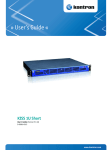
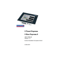


![[Insert the picture here]](http://vs1.manualzilla.com/store/data/005750886_1-61b7896b0a61bec1f004b64a994fc9d3-150x150.png)