1
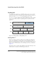
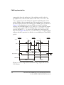
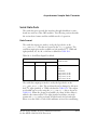
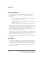
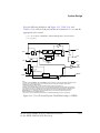
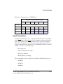
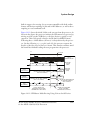
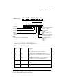
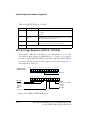
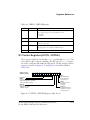
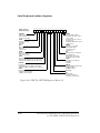
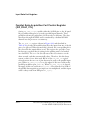
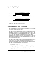
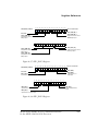
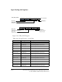
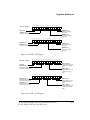
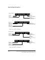
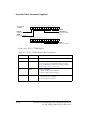
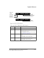
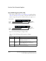
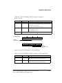
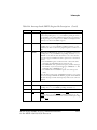
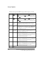
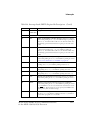
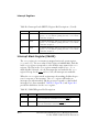
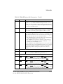
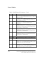
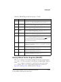
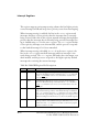
Serial Ports
• When the MCEA or MCEB bits are cleared (=0), all multichannel operations are disabled.
Multichannel operation is activated three serial clock cycles after the MCEA
or MCEB bits are set. Internally-generated frame sync signals activate four
serial clock cycles after the MCEA or MCEB bits are set.
Setting the MCEA or MCEB bits enables multichannel operation for both
receive and transmit sides of the SPORT0/1, SPORT2/3 or SPORT4/5
pair. A transmitting SPORT0, 2, or 4 must be in multichannel mode if
the receiving SPORT1, 3, or 5 is in multichannel mode.
Select the number of channels used in multichannel operation by using
the 7-bit NCH field in the multichannel control register. Set NCH to the
actual number of channels minus one:
NCH
= Number of channels – 1
The 7-bit CHNL field in the multichannel control registers indicates the
channel that is currently selected during multichannel operation. This
field is a read-only status indicator. The CHNL(6:0) bits increment modulo
NCH(6:0) as each channel is serviced.
The 4-bit MFD field (bits 4-1) in the multichannel control registers
(SPMCTL01, SPMCTL23, and SPMCTL45) specifies a delay between the frame
sync pulse and the first data bit in multichannel mode. The value of MFD is
the number of serial clock cycles of the delay. Multichannel frame delay
allows the processor to work with different types of telephony interface
devices.
A value of zero for MFD causes the frame sync to be concurrent with the
first data bit. The maximum value allowed for MFD is 15. A new frame sync
may occur before data from the last frame has been received, because
blocks of data occur back to back.
ADSP-2136x SHARC Processor Hardware Reference
for the ADSP-21362/3/4/5/6 Processors
4-29