1
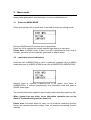
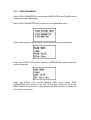
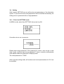
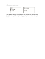
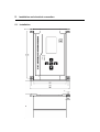
Universal monitoring controller UC-5m
User’s Manual
Single-line lubrication control
Dual-line lubrication control
Suzhou Leetern Industry Control
Ver 1.0
Oct. 2011
Contents
1.Display and control panel
1.1
LED pilot lights
1.2
Keys
1.3
LCD display
2.Main lubrication function
2.1
Auto lubrication
2.1.1
Timer lubrication
2.1.2
Counter lubrication
2.1.3
Combined control mode
2.2
Insert lubrication
2.3
External control interlock
2.4
Fault monitoring
2.6
Information storage
3. Menu mode
3.1
Enter menu mode
3.2
Lubrication
3.3
View information
3.3.1
View system information
3.3.2
View parameters
3.3.3
View monitoring information
3.4
Setting
3.4.1
Enter setting menu
3.4.2
System setting
3.4.3
Parameters setting
3.4.4
Monitoring setting
4. Faults
4.1
Oil/grease level monitoring and gives alarm
4.2
Compressed Air pressure monitoring and alarm
4.3
Oil/grease pressure monitoring and alarm
4.4
Cycle Switch signal monitoring and alarm
4.5
Fault message display and handle
5.
Installation and electrical connection
5.1
Installation
5.2
Power supply
5.3
Electrical connection
6. Technical specification
Universal Monitoring Controller UC-5 is designed for controlling and
monitoring of both single line and dual line Lubrication systems. It is
applicable to lubrication systems for all kinds of machinery equipment.
The controller UC-5 intuitively displays operating information like operating
state and parameters with LCD. It is easy to use. UC-5 stores configuration
data and parameters in EEPROM, which made those data can be stored
safely for long time.
UC-5 is of completely sealed design, Its protection grade reaches IP65, thus it
can work steadily in severe Industrial working environment.
Safety Warning!
Mounting and connecting controller UC-5 must be done under power cut-off
condition. Hot-line work is prohibited to prevent electric shock hazard. Ground
terminal of UC-5 must be well grounded. The system should be protected with
specified fuse to ensure controller safe and personal security.
UC-5 must be mounted, tested and maintained only by trained qualified
personnel. In order to guarantee system operating safely and properly,
its safe condition should be periodically inspected.
Although UC-5 complies with relevant safety technical requirements, the
use of the controller may still entail dangers leading to personal injury of
the user or third parties or damage to property. Therefore, the operation
must strictly comply with operation manual. Errors that may affect
safety must be rectified immediately.
UC-5 is designed for controlling and monitoring centralized lubrication
systems. The user himself shall be liable for any damage caused by
improper use.
1. Display and control panel
Display and control panel of UC-5
1.1
LED pilot lights
POWER – power pilot light. When power supply to the controller is normal,
the green pilot light of POWER is on.
INFO – Information pilot light. When controller detects fault, the red pilot light
will be continuously flashing.
1.2 Keys
-Key UP. Scroll up key. When selecting menu, press key UP to scroll up
the menu; under setting mode, to increase the displayed value at cursor
position with this key.
-Key DOWN. Scroll down key. When selecting menu, press key down to
scroll down the menu; under setting mode, to decrease the displayed
value at cursor position with key DOWN.
-Key LEFT. Scroll left key. To move cursor left in setting mode.
-Key RIGHT: scroll right key. To move cursor right in setting mode.
-Key OK: To start setting mode with key OK in display mode; Confirm
menu or programmed parameters; this key also has function to exit fault
state or advance terminate OIL DRAINING.
1.3 LCD monitor
LCD displays operating status and parameters of the lubrication system.
When controller is operating, LCD mainly displays current states.
PAUSE means lubrication system is now in PAUSE state. Displayed content
may be: LUBRICATION, PAUSE and STOP etc.
TIMER means PAUSE control mode is TIMER mode. Displayed content may
be TIMER (timer mode) and COUNTER (counter mode).
“0024h 00min 00s” shows the preset PAUSE time. (Preset PAUSE time is 24
hours.)
“0016h 30min 00s” shows the remaining PAUSE time at present . (There is
still 16 hours 30 minutes left for PAUSE state.)
In LUBRICATION phase, the two values represent preset value and remaining
value for LUBRICATION.
Under external control or inserted lubrication states, when system detects
faults, LCD will display other messages. Please refer the detail information in
follow chapters.
2. Main lubrication functions
Controller supports multi lubrication control modes to meet actual lubrication
project needs.
Lubrication control modes include Auto lubrication mode, insert lubrication
mode, external control interlock mode. During controller operation time, it can
monitor external fault signal. Once controller detects any fault, it will gives
alarm signal and get into stop state.
2.1
Auto lubrication
Under normal operating conditions, if the controller is set as AUTO lubrication
mode, the controller controls lubrication system working in continuous cycle of
“PAUSE-LUBE-PAUSE…..” Auto lubrication control mode have two modes,
TIMER control mode and COUNTER control mode.
2.1.1 Timer Lubrication
TIMER lubrication control is the basic lubrication control mode. In this way,
controller is set as TIMER mode for both LUBRICATION and PAUSE, and
controller will automatically carries out the lubrication task in continuous cycle
of “Timer mode of PAUSE-Timer mode of LUBE-Timer mode of PAUSE…..
In TIMER control mode, the 2nd line of the message displayed on LCD monitor
is TIMER. This means it is operating in TIMER mode. If the lubrication system
is now in LUBRICATION state, the 1st line of the message displayed on LCD
monitor is LUBRICATING. If system is right in PAUSE state, the 1st line is
PAUSE, and the 3rd line and 4th line will show the corresponding preset
parameter and remaining value.
In TIMER control mode, PAUSE time and LUBRICATION time can be set
separately. And programmable PAUSE time range is 0min to 9999h 59min,
programmable LUBRICATION time range is 1s to 99h 59min 59s.
In TIMER control mode, PAUSE time can be set as “0”, In this case, lube
system operates in LUBRICATION state all the time and will not go to PAUSE
state any more.
2.1.2
Counter lubrication
LUBRICATION control can be set as COUNTER mode according to
lubrication requirement. This is very useful for those single-line systems that
need to be lubricated according to distributors’ movement times, or dual-line
lubrication system that needs to be lubricated according to movement times of
pressure difference switch at the end of the lines.
In COUNTER control mode, controller will automatically carries out the
lubrication task in continuous cycle of “TIMER mode of PAUSE - COUNTER
mode of LUBRICATION – TIMER mode of PAUSE…. When preset PAUSE
time ends, system goes into LUBRICATION state. In lubrication state,
controller receives external COUNTER signal, when it receives the preset
COUNTER signal numbers, lubrication state ends and system goes back to
PAUSE state again.
In COUNTER control mode, the 2nd line of the message displayed on LCD
monitor is COUNTER, which means lubrication system is now in COUNTER
control mode.
Counter signals (counting semaphore) must be input controller via CS-1
terminal. Although CS-1 is served as counter signal input terminal, this does
not affect its CS (Cycle Switch) monitoring signal input function.
It is recommended to initiate CS monitoring function, to enable controller to
monitor if the system operates within the specific lubrication time.
2.1.3
Combined control mode
In special cases, PAUSE can be set as COUNTER control mode;
LUBRICATION can be set as TIMER mode or COUNTER mode. In this
control mode, controller can control large gear or chain’s lubrication.
2.2
Insert a lubrication
Under normal situation, controller controls lubrication system working in
continuous cycle of “PAUSE-LUBE-PAUSE…..”. When user need to do
lubrication system’s testing and maintenance, or wants to lubricate the system
occasionally, INSERT A LUBRICATION function will help.
It is easy to insert lubrication in MENU mode. After initiate a lubrication,
controller will stop current PAUSE or LUBRCATION task and perform the
inserted lubrication. When the preset lubrication value ends, system will go to
PAUSE state.
During the inserted lubrication period, displayed information on LCD is
“LUBRICATING﹒”. The mark ”﹒” follows LUBRICATING remind user it is a
INSERTED lubrication.
The inserted lubrication operation can be early ended by briefly press key OK .
When inserted lubrication finishes or being manually ended, system
automatically returns back to PAUSE state.
2.3 External control
Some lubrication system needs to be interlocked control with host machine of
the lubricated equipment. In this case, user may initiate the EXTERNAL
CONTROL function.
Once EXTERNAL CONTROL is initiated, controller can accept external
interlock signal’s control. When external interlock switch closes, controller
performs normal control. When external interlock switch opens, controller
pauses its control and the information displayed on LCD is:
When external interlock switch closes again, controller will then continue its
control tasks from the interrupted point.
During PAUSE state under external control mode, controller’s operation will
be frozen. In this case, controller does not perform any lubrication control and
fault monitoring task.
2.4
Fault monitoring
Controller has perfect fault monitoring function that can monitor lubrication
system’s operation situation. Once it detects fault, the controller will stop the
system and then gives alarm.
Controller has the following monitoring functions:
Lubrication oil level monitoring
Compressed air pressure monitoring
Lubrication oil pressure build-up situation monitoring
Cycle Switch monitoring. There are 3 CS monitoring levels. CS
monitoring can be set as OFF, ALARM BUT NOT STOP and ALARM AND
STOP.
System power down monitoring
For detailed information, please refer to relevant Fault monitoring chapters.
2.5
Information storage
Controller can store preset working parameters permanently. Those
parameters will not lose because of power down.
Once SYSTEM POWER DOWN MEMORY function is initiated, controller will
automatically store those operational states and remaining parameters at the
point of power down when power down occurs. And controller continues carry
out operation from the interrupted state when power re-supplied again.
Please note: Due to the situation that the power supply to controller is
different from that to lubrication system, user should use power down memory
function cautiously. Because this may cause lubrication system and control system out of
synchronous.
3. Menu mode
In menu mode, user can set every function and control parameters, to review
those preset parameters and information, to insert a lubrication etc.
3.1
Enter into MENU MODE
Press and hold key OK for more than 3 seconds to enter into setting mode.
Use key DOWN and UP to select item to operate/set.
Press key OK to confirm the current selected item and go to next step.
Please note: In MENU mode, if there is no KEY operations for more than 2
minutes, controller will automatically goes back to display mode.
3.2
Lubrication (Insert lubrication)
Once the item LUBRICATION in menu is selected, controller will quit MENU
mode then goes to LUBRICATION phase (this is INSERTED LUBRICATION).
Starting value of inserted LUBRICATION is the preset time value of
LUBRICATION. It reduces progressively until lubrication ends and goes to
PAUSE state again.
The inserted lubrication operation can be early ended by briefly press key OK.
When system has any faults, insert lubrication operation can not be
started. Troubleshooting must be done first
Please note: Controller does not carry out oil pressure monitoring function
during the inserted lubrication phase even oil pressure monitoring function
initiated.
3.3
View information
Enter into VIEW INFORMATION menu to review every function and settings
of the lubrication system. But user cannot change those settings under this
mode. This can avoid those settings being modified accidentally.
3.3.1
View system information
VIEW SYSTEM INFO. can view system information and those function items
that do not belong to lubrication control function.
Select VIEW SYSTEM INFO item to enter into view system information menu.
LCD monitor first display controller’s serial number and P.D. MEMORY (Power
Down MEMORY) setting.
Press key DOWN, LCD monitor displays EXTERNAL CONTROL setting and
“----END----”, END means VIEW SYSTEM INFO. menu ends.
Press key OK to quit MENU MODE and gets back to operational state display
mode. Or press key UP to return last screen.
3.3.2
VIEW PARAMETER
Select VIEW PARAMETER to view preset LUBRICATION and PAUSE control
modes and control parameters.
Select VIEW PARAMETER item to enter into view parameter menu.
LCD monitor begins to show PAUSE control mode and control parameter.
Press key DOWN, LCD monitor displays LUBRICATION control mode and
control parameter.
Press key DOWN, LCD monitor displays END, which means VIEW
PARAMETER menu comes to the end. At this time, press key OK to quit
MENU MODE and gets back to operational state display mode. Or press key
UP to return last screen.
3.3.3
VIEW MONITOR (review monitoring function settings)
Select VIEW MONITOR to view monitoring function setting situation.
LCD monitor begins to show CS (Cycle Switch) monitoring setting situation. If
the monitoring function of one Cycle Switch is closed, LCD shows OFF. (For
example: CS2 monitoring function is OFF. ) If monitoring function of one Cycle
Switch is initiated, then the corresponding CS monitoring setting will be the
preset monitoring time value.
Once CS monitoring is initiated, there will be a letter postfix “-A” or “-T” follows
the CS monitoring time value to show monitoring level.
The postfix “-A” means CS monitoring level is ALARM BUT NOT STOP. When
controller detects CS error, controller will give alarm signal, but it will not stop
the lubrication system; Postfix “-T” means CS control level is STOP. When
controller detects CS error, it will give alarm and get the lubrication system
stop to wait for user to handle faults.
Press key DOWN, LCD displays the setting situation of CS3 and CS4.
Press key DOWN, to see monitoring setting situation of other Cycle Switches.
When all Cycle Switches are displayed, press key DOWN to display OIL
LEVEL and CA (Compressed Air pressure) monitoring function settings.
Press key DOWN, LCD displays OIL PRESSURE monitoring setting and
“----END----“, this means VIEW SYSTEM INFO. menu comes to the end.
Press key OK to quit MENU MODE and gets back to operational state display
mode. Or press key UP to return last screen.
3.4
Setting
With function SETTING can set all function and parameters of the lubrication
system. To prevent functions and parameters will be modified accidentally, the
setting menu is protected with a 4-digit password.
3.4.1
Enter into SETTING mode
In MENU mode, select item SETTING, then press key OK.
Controller will then ask for password.
Please input 4-digit password. If the password is correct, user can go to next
step. If user continue input wrong password 3 times, controller automatically
exits MENU mode and goes back to display mode.
The initial password is“0000”
After enter the setting mode, all functions and control parameters of UC-5 can
be modified.
3.4.2
SET SYSTEM ( System setting)
Select SET SYSTEM and press key OK to enter system setting menu. This
menu is mainly used to set those items that relate to system management.
Select PASSWORD item, press key OK, the least significant digit of password
then start blinking (the blinking position is called cursor position). User can
modify password at this time.
Use key DOWN and UP to change the value at cursor position. Use key LEFT
and RIGHT to move the cursor position.
Press key OK to confirm the new password.
Password setting range is 0000~9999.
Press key DOWN, then select item P.D. MEMORY (Power Down memory)
and press key OK. At this time, the next line on the screen begins to blink.
Use key DOWN and UP to change the setting.
OFF: to shut down the power down memory function.
ON: to initiate power down memory function.
Press key OK to confirm the new P.D. MEMORY setting.
Press key DOWN, LCD then displays EXTERNAL CONTROL setting and
“----END----“(EXIT SETTING). Select EXTERNAL CONTROL, then press key
OK, the next line begins to blink at this time. User may change the setting with
key DOWN and UP.
OFF: to shut down external control function.
ON: to initiate external control function.
Press key OK to confirm the new setting.
If user select “----END----“(EXIT SETTING) and press key OK at this time,
controller will quit MENU mode and gets back operational state display mode.
If press key UP at this time, then goes back to last function.
3.4.3
SET PARAMETERS (Parameter setting)
SET PARAMETER menu is used for LUBRICATION and PAUSE control mode
and control parameters setting.
Select SET PARAMETER and press key OK, LCD displays:
then select PAUSE MODE and press key OK, the setting of PAUSE MODE
begin to blink, which means this setting can be changed. Use key DOWN and
UP to select specific control mode. There are two control modes TIMER and
COUNTER for user to choose from. Press key OK to confirm the new control
mode.
Press key DOWN, select PAUSE VALUE and press key OK, the cursor
position digit of the preset PAUSE VALUE begins to blink, user can change
the PAUSE VALUE.
Use key DOWN and UP can change the digit at cursor position. Use key
LEFT and RIGHT can move cursor position.
Please note: controller does real-time checking on the parameters change
situation. Once the new value input is beyond the programmable range,
controller then refuses the change.
PAUSE value programmable range is 0-9999h 59min.
If PAUSE is set as COUNTER mode, then the programmable range is 0-9999
9999.
Press key OK to confirm the new PAUSE VALUE setting.
With the same operation steps can change LUBRICATION MODE and LUBE
VALUE settings. Please note: LUBRICATION VALUE cannot be set as 0
(zero). If LUBRICATION MODE is set as TIMER, then the programmable
LUBE VALUE range is 1s – 99h 59min 59s. If LUBE MODE is set as
COUNTER, the programmable LUBE VALUE range is 1-999 999 impulses.
Press key DOWN, LCD displays END, which means parameter setting menu
comes to the end.
At this time, if user select END and press key OK, controller will quit MENU
mode and gets back operational state display mode. If press key UP at this
time, then user can select last programmed item.
3.4.4
SET MONITOR (Monitoring function setting)
SET MONITOR menu is used to set monitoring functions.
Select SET MONITOR and press key OK, LCD then displays
If monitoring function of one CS is shut down, the corresponding setting is
OFF. If monitoring function of a CS is initiated, then the displayed setting is
preset monitoring time value and monitoring level.
Use key DOWN to select a CS and press key OK. If monitoring function of the
selected CS is already initiated, the least significant digit of the monitoring
time value on the next line begin to blink, user can edit the parameter. If the
monitoring function of the selected CS is shut down, then the monitoring time
value is showed as all digit “0” and the digit at cursor position begin to blink.
Use key DOWN and UP can change the digit at cursor position. Use key
LEFT and RIGHT can move cursor position.
Programmable monitoring time range of CS is 0-17h 59min 59s. If the value is
set as 0, which means the monitoring function of this CS is shut down.
If CS monitoring time value is not set as 0 (zero), which means CS monitoring
function is initiated. Press key OK to get into CS monitoring level setting.
Postfix parameters (postfix may be “-A” (give alarm but not stop system) or
“-T” (alarm and stop the system)) that represents monitoring level is flashing
and user can use key UP or DOWN to change CS monitoring level now.
For example, CS1 monitoring level is changed to “-T”, this means once CS1
has faults, the system will stop.
After user select the proper CS monitoring level, press key OK and the postfix
of the monitoring level stop flashing. And the setting is stored until next
change via setting.
If system is stop due to CS error, to turn off CS monitoring function or lower
monitoring level (change “-T” to “-A”), controller will control and adjust the
system accordingly.
Press key DOWN or UP can view and set all Cycle Switches’ monitoring
function.
Press key DOWN until LCD displays
User then can set oil level monitoring and Compressed Air pressure
monitoring functions.
Factory setting for LOW OIL LEVEL monitoring is ON. Use key DOWN and
UP to select LOW OIL LEVEL, then press key OK to get into setting menu. At
this time, the preset content of the function is blinking, use key DOWN or UP
to change the setting. The setting can be ON or OFF.
Press key OK to confirm the new oil level monitoring function.
Please note: we DO NOT suggest shutting down oil level monitoring function
unless for temporary test need. If set LOW OIL LEVEL as OFF means to shut
down the oil level monitoring function, this will make the lubrication system in
a state of insecurity.
Select CA MONITORING, the press key OK to change compressed air
pressure monitoring setting. At this time, the preset content of the function is
blinking, use key DOWN or UP to change the setting. The setting can be ON
or OFF.
Press key OK to confirm the new CA MONITORING setting.
Press key DOWN, LCD displays OIL PRESSURE setting.
Select OIL PRESSURE and press key OK to change the oil pressure
monitoring setting. At this time, the preset content of the function is blinking,
use key DOWN or UP to change the setting. The setting can be ON or OFF.
Press key OK to confirm the new OIL PRESSURE setting.
Press key DONW. At this time, if user select “----END----“(EXIT SETTING) and
press key OK, controller will quit MENU mode and gets back operational state
display mode. If press key UP at this time, then user can select last
programmed item.
4. Faults
Controller has ability to monitor the lubrication system and detect faults, gives
alarm signals, which protect the system operate safe and reliable.
4.1
Oil level monitoring and alarm signal
Controller can detect oil level situation via oil level switch. When it detects the
oil level is low, it gives alarm signal and get the system into stop state. And,
fault information displayed on LCD will be:
Oil level switch must be Normally Closed switch. Please refer to chapter 5,
<installation and electrical connection> for the connection.
Factory setting of oil level monitoring is ON. If it is necessary, user may shut
down this function in setting menu.
4.2
Compressed Air pressure monitoring and alarm signal
Some lubrication systems use compressed air as the driving force. In this
case, compressed air pressure need to be monitored to ensure lubrication
system operates properly.
Use Normally Closed pressure switch to detect the CA pressure. The pressure
switch opens once pressure is too low. When controller detects the pressure
switch is open, it gives alarm signal and gets the system into stop state.
The Compressed Air pressure fault information displayed on LCD will be:
Factory setting of CA PRESSURE monitoring is ON. If it is necessary, user
may shut down this function in setting menu.
4.3
Oil pressure monitoring and alarm signal
If the pressure built-up situation during lubrication period needs to be
monitored, user may set OIL PRESSURE monitoring setting as ON (to initiate
oil pressure monitoring function)
Once this function is initiated, controller will monitor the oil pressure switch
condition during lubrication period. If the pressure is not in closed condition
when the lubrication period finish, controller will give alarm signal and get the
system into stop state.
Please note: If the lubrication is INSERTED lubrication, then the oil pressure
monitoring function will not be carried out during lubrication period.
Factory setting of OIL PRESSURE monitoring is OFF. If it is necessary, user
may initiate this function in setting menu.
4.4
Cycle Switch signal monitoring and alarm signal
For systems that use distributors to distribute oil/grease, or dual-line
lubrication system that uses end pressure difference switch to control
lubrication process, user need to use CS (Cycle Switch) monitoring function to
monitor the functioning of the system.
Controller UC-5 can monitor 8 CS at the same time (max.). Each CS can be
individually initiated or shut down. The CS monitoring time and monitoring
level for those initiated CS can be set individually.
The role of monitoring time is:
Each CS (Cycle Switch) corresponding matches an internal timer Tc. When
lubrication starts, Tc begins to countdown. If CS signal is received during the
countdown, Tc clears and re-start countdown. If no CS signal received until
the Tc countdown to the preset monitoring time, this means CS error occur. If
CS monitoring level is set as “-A”, controller will give alarm signal to remind
user the CS fault and carry on lubrication task. If CS monitoring level is set as
“-T”, controller will give alarm signal and get the system into stop state at the
same time.
4.5
Fault display and handle
When controller detects fault, LCD monitor will display corresponding fault
information in text, meanwhile, FAULT pilot light (INFO)on control panel
flashes. Fault output relay’s contact open to transfer the fault signal to control
room or to connect other control system.
Inside controller, there is fault alarm drive to directly drive 220V alarm device
like warning light, alarm bell and so on.
If power down memory function is enabled, the fault information that caught
by controller will be stored in EEPROM. It will not disappear (even power-off)
until user clears the fault manually.
If the fault is just a warning of general nature (example: one CS monitoring
occur warning fault), the information displayed on LCD will be switching
between FAULT INFO. screen and normal operational screen, and switching
time is 1 second. If the fault is a serious fault that causes system stop, LCD
will display the fault info. only. When WARNING INFO. and STOP INFO. exist
at the same time, controller will alternately display the two types of
information.
As show in the figures above, in the left figure, the first line displays ”STOP”,
which means the lubrication system stop already. Controller also points out
that the stop caused by S2 (Cycle Switch 2) failure. In the right figure, the first
line displays “NO SIGNAL”, which means this is warning information.
Controller also points out the cause of the failure is CS1.
During the period that controller is switching between two screens, press and
hold key UP, controller will pause to switch the screens and the screen
displayed (at the time when user press key UP) will stay. This helps user to
get clear information.
When release key UP, controller will continue switching screen. If more than
one CS occur warning faults or stop faults, controller will show all the failure
CS information on the screen.
After handling the fault, briefly press key “OK” to quit Fault State and clear
fault information on LCD. Controller then goes back to normal lubrication cycle.
But if the reason that causes the fault still exists, the above operation does not
work.
5.
Installation and electrical connection
5.1
Installation
Installation dimensions of the controller are show as figure above.
The control panel of the controller should be perpendicular to the earth, and
controller to be fixed on a place that is secure, non-violent vibration, no
corrosive atmosphere and out of direct sunlight. It is recommended to fix the
controller with machine screws. (Self-tapping screws should not be used to
prevent fall off damage to the controller with time passing.)
5.2
Power supply
Required power supply to the controller is: Voltage: 18-32V DC.
For the controller is designed with multiple level power supply filtering, UC-5
can effectively filter those strong interference that superimposed in power
supply, which ensures control system work well. Even so, it is still necessary
to supply the controller a separate power supply and avoid being power
supplied together with large-scale electrical equipment (such as frequency
transformer) that creates electrical interference easily. If the interference of
the power supply is too strong that the controller cannot work steady, user
may connect another filter to the power input side of the controller.
5.3
Electrical connection
Cut off power first. Carefully pry off the small covers at four corners with
small slotted screwdriver, remove four screws inside. Lift top case and
disconnect the flat cable that connecting the Operate & control unit with
Power and Input Output unit.
Put the top case aside carefully, the inside Power and InputOutput unit is
shown as figure.
Connect external electrical equipment onto this Power and Input Output unit.
Electrical input and output terminals are indicated in the figure. From left to
right (face to the PCB), the terminal code is 1, next is “2”, “3”etc. The
definition of each terminal is as follow. (Terminals that are not listed in the
follow chart are reserved terminals, please DO NOT connect onto them.)
Power input terminal J3
Terminal
code
1
24V
DC 24V input
2
0V
DC 0V input
Definition
instruction
Output terminal J4
Terminal
code
1
Pump control A
24V power supply
2
Pump control B
pump power supply input
3
Alarm output A
24V power supply
4
Alarm output B
Output 24V alarm signal
5
SL output A
24V power supply
6
SL output B
Connect external 24V pilot light.
7
Reserved
8
Reserved
9
Reserved
10
Reserved
Definition
instruction
For pump
For alarm
For signal
1st input terminal JP1
Terminal
Definition
code
1
DC 24V
instruction
Connect oil level switch B
2
Oil level signal input
Connect oil level switch A
3
DC 0V
DC 0V circuit
4
DC 24V
Connect oil pressure switch B
5
Oil pressure signal input
Connect oil pressure switch A
6
DC 0V
DC 0V circuit
7
DC 24V
Air pressure signal input B
8
CA pressure signal input
CA pressure signal input A
9
DC 0V
DC 0V circuit
Oil level
signal
Oil pressure
signal
CA pressure
signal
2nd input terminal JP2
Terminal
Definition
code
1
DC 24V
2
instruction
External control signal input B
External control signal input External control signal input A
3
DC 0V
DC 0V circuit
4
DC 24V
Input B for CS1
5
Input for Cycle Switch 1
Input A for CS1
6
DC 0V
DC 0V circuit
7
DC 24V
Input B for CS2
8
Input for Cycle Switch 2
Input A for CS2
9
DC 0V
DC 0V circuit
External
control
signal
Cycle
Switch 1
Cycle
Switch 2
3rd input terminal JP3
Terminal
definition
code
1
DC 24V
instruction
Input B for CS3
2
Input for Cycle Switch 3
Input A for CS3
3
DC 0V
DC 0V circuit
4
DC 24V
Input B for CS4
5
Input for Cycle Switch 4
Input A for CS4
6
DC 0V
DC 0V circuit
7
DC 24V
Input B for CS5
8
Input for Cycle Switch 5
Input A for CS5
9
DC 0V
DC 0V circuit
Cycle
Switch 3
Cycle
Switch 4
Cycle
Switch 5
4th input terminal JP4
Terminal
Definition
code
1
DC 24V
Instruction
Input B for CS6
2
Input for Cycle Switch 6
Input A for CS6
3
DC 0V
DC 0V circuit
4
DC 24V
Input B for CS7
5
Input for Cycle Switch 7
Input A for CS7
6
DC 0V
DC 0V circuit
7
DC 24V
Input B for CS8
8
Input for Cycle Switch 8
Input A for CS8
9
DC 0V
DC 0V circuit
Cycle
Switch 6
Cycle
Switch 7
Cycle
Switch 8
When delivery, there is no openings on the controller’s shell (case). User
should make openings and connect wires depend on his own needs. Wires
should be brought out from PG waterproof joint to keep the tightness of the
controller.
In order to protect the Power and InputOutput unit from damage, please
remove it before making holes.
Typical connection method for internal circuit and external circuit are as follow
figures:
Please note:
① The 24V power that the terminal supplies is only for sensors and external
switch’s excitation. Due to its limit load capacity, it is NOT allowed to use
for any other purposes. Otherwise, it may cause controller erro
② In order to meet control requirements, proximity switches must be
Three-wire PNP proximity switch of no load current≤50mA.
6. Technical specification
Voltage of power supply
18V~30V DC
Max. output
>5A (resistive load)
Lubrication time range
1s~99min 59s
Pause time range
0~9999h 59min
Lubrication counting range
1~999 999
Pause counting range
0~9999 9999
External input signal
5V ~30V DC,low level effective
External switch signal
N.C. contact, open effective.
Cycle Switch monitoring
8 Cycle Switches
Cycle Switch monitoring time
0~17h 59min 59s
Local fault indication
5A Max
Fault relay output
250V AC,5A Max,N.C.
Operation temperature
-20℃~+55℃
Fuse Spec.
250V 0.5A
Protective grade
IP65(fully against dust and moisture)
Without our written permission, any forms of translation, excerpt, copy,
print and reproduce of this USER MANUAL and its content is prohibited.
We reserve all rights to this USER MANUAL. We reserve the right to
revise it without prior notice.
Manufacturer: Suzhou Leetern Industry Control
Office: Rm. 501, Bldg. 45, No. 188, West Guoxin Road,
Wuzhong Dist. Suzhou, China
Technical Support Fax: +86-512-68661838
Technical Support Email: [email protected]
[email protected]
Website: http://www.leetern.com