1
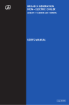
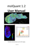
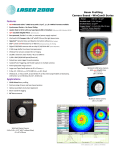
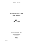
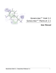
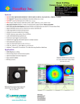
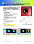
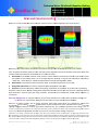
Te echnical N Note: WinCamD B Baseline S Setting DataRa ay Incc. Win nCamD Series s Tap perCamD Seriies Win nCamD Baseline e Settingg – DataRayy Confidentiaal A Applies to: All current WinCaamD series pro oducts. Software version 7.1H H10 & higher ffor the currentt iteration. SSummary: Thhis Technical Note describes the t four baseline setting moddes of DataRayy WinCamD series software. Note: Competitor assertions that theirs is the t only beam profiler algoriithm that sets the baseline in n the center off the noise t electrronic noise belo ow zero are sim mply incorrectt. and does not truncate Auto‐base eline: This defaault real‐time mode, presentt in various iteerations since tthe 90’s, hand dles most beam ms. On the laser poin nter in the exaample above, the un‐averagged diameter rreadings in a ttypical lab envvironment aree stable to ≈ 0.05% rm ms, ≈ 0.25% pkk‐to‐pk, a direcct consequence e of the auto‐bbaseline algoritthm stability. Baseline Lock: L Use with beams which overfill the sen nsor. Locks autto‐baseline at iits current valu ue. Backgroun nd Subtraction n: Use if there is substantial optical o backgroound to deal w with. HyperCal™ ™: Real‐time su ubtraction of electronic e shad ding. Importantt in Use equivaalent slit mode & with comett tailing. Real‐time, fram me‐by‐frame, baseline b settin ng & the background subtracttion option haave been features of DataRayy software ssince the nineties ‐ what we e simply call ‘doing it properly’. Auto‐baselline has recenttly been furtheer refined. Hyp perCal is a new feature. TTechnical Bacckground: For a perfect Gauussian, the 1/ee2 beam diametter error is neaarly twice the bbaseline settingg error. e.g. a 0.1% error in the baseline seetting results in n a 0.18% erro r in the measuured beam diam meter. TThere are no perfect senso ors, and no perfect electronics. Real wo rld cameras m must set a baaseline for anaalysis that o zero irradiance. Negative irrradiance doess not exist, butt electronic noise and offsetss at the input to the ADC corresponds to (Analog to Diggital Converter) can drive signal above an nd below the zero irradiancce equivalent input voltage. [ADC’s are unipolar so zero irrradiance is alwayss a non‐zero voltage at the ADC inpu ut, servoed to aroound 2% of the AD C range in DataRaay systems with AD DC’s external tto the sensor.] Be ecause backgro ound & noise can c vary over time, real‐time baseline settin ng is important. [Historically, noise, offsets and offset drifts were higher h than with current generati on sensors and eelectronics, and p processing powerr was lower. O easurement sessio on allowing everytthing to stabilize, taking and processsing a reference frame in the One approach was to spend time at the start of a me d ming a live image co orrection based on subtraction of th his processed refeerence data. This w was then applied to all subsequent b beam images dark, and perform in the session untiil a recalibration was w deemed appro opriate. DataRay considers now this approach no longger necessary or ap ppropriate.] W WinCamD Baseline Setting Ver. 1202a 1 Page 1 of 3 D DataRay Inc. Bella Vista, CA (203) 2 210-5065 www.d dataray.com Implementation Descriptions: Real‐time auto‐baseline ‐ No user intervention required. a) Philosophically, the aim is to establish and subtract the ADC level corresponding to zero irradiance. This requires us to find the peak in the levels near zero irradiance outside the beam area. b) If the Capture Block is H x V pixels, the software inscribes a circle of diameter H or V, whichever is smaller. Pixels outside this circle but within the Capture Block constitute the data to be processed for baseline setting. E.g. For a square capture region, this selects the corners of the image – the hatched areas above. c) The software creates an internal histogram of ADC level versus number of pixels at this level. It also performs a 32 frame rolling average of the histogram. Because a 16‐bit ADC word has 65,536 levels, the histogram is smoothed by a 32 level wide, equal weight, smoothing function (0.05% of the total ADC range). Without this smoothing, such a histogram is too peaky to be useful. d) The software analyzes the histogram to determine the first peak above zero in the histogram, Ibaseline, typically around the 1300 level (the ≈2% level of the ADC range). # in Level e) Create the array to be processed as an image: IImage(x,y) = IRaw(x,y) ‐ Ibaseline This approach: Level Is the default mode of operation and works really well for the vast majority of beams, those roughly centered in the Capture Block but which do not overflow the Capture Block. Real‐time. No ‘accuracy’ versus ‘ease of use’ tradeoff required. Requires no warm‐up time and no user intervention. Works with Auto‐exposure & Auto‐gain, as well as at fixed Exposure &/or Imager Gain. Is simply confirmed by observing the profile baseline in log 40dB mode. Residual noise is typically below 0.1%. May be further improved by simply using the Average function. Baseline Lock ‐ for large beams which overfill the camera. Set once. [User Manual Sec. 3.4, p. 56] a) Philosophically, the aim is to establish and subtract the ADC level corresponding to zero irradiance for beams which overfill the camera, negating histogram peak finding in the default auto‐baseline function. b) The padlock style Lock and Unlock buttons allow you to Lock the baseline at the current level set by the auto‐ baseline function, above. This allows the measurement of beams which overfill the sensor and are therefore too large to allow the determination of a good zero level while the beam is on the camera. c) With the beam on the camera, uncheck auto exposure. Then block the beam and click on the Lock padlock‐style button. Then unblock the beam. The zero level from which clip levels are determined will be now be based upon the level determined while the beam was blocked. Obviously (?), if beam wings are absent, second moment (4σ) widths calculated for such a beam are invalid. To disable this feature, click on the Unlock padlock button. Background Subtraction ‐ for beams on top of an optical background which needs to be rejected. Set once. [User Manual Sec. 3.4, p. 57] a) Philosophically, the aim is to subtract an unwanted optical background. b) Right-click on the Exposure time box & disable auto-exposure. Click OK. If appropriate set Average=20, especially if the background to be subtracted is noisy. c) Click the button to initiate background subtraction. The box shown right will appear. Block the beam, allow any selected averaging to complete, and then click OK. The captured background (optical and electrical) is subtracted from subsequent images. If Average is still engaged, subtraction will be gradual. d) Auto-baseline operates on the difference image. e) Press the bracket button to turn it off. WinCamD Baseline Setting Ver. 1202a Page 2 of 3 DataRay Inc. Bella Vista, CA (203) 210-5065 www.dataray.com HyperCal™ ‐ for occasions where ‘shading’ in the electrical offset need to be rejected. Set once. [User Manual Sec. 3.4, p. 57] a) Philosophically, the aim is to subtract any unwanted electronic offset which is non‐uniform across the sensor. Tends to matter most when Use Equivalent Slit is engaged, when baseline tilt – always present but normally negligible for practical purposes – can become significant in the integrated line profile. Can be engaged at any time for any reason, at exposures >0.4 ms. b) HyperCal alternately takes exposures at the lowest possible exposure and at the auto or set exposure and differences the frames. Auto-baseline operates on the difference image. HyperCal therefore completely removes electronic offsets at the ADC that do not result from the presence of an image. c) Press the button again to turn it off. Log profile displays, no averaging. Without HyperCal™ 0.3% noise + baseline tilt WinCamD Baseline Setting Ver. 1202a With HyperCal™ Noise <0.1% & flat baseline Page 3 of 3 DataRay Inc. Bella Vista, CA (203) 210-5065 www.dataray.com