1
Diagnostic Rolling Element
Analysis Module
(DREAM)
Version 4.x
for the “Bruel&Kjaer” Type 7107-M Sentinel software
and Type 2526 data collector
USER'S MANUAL
OPERATOR'S MANUAL
Copyright 2003,05
VibroTek, Inc.
Copyright 1996,97
VAST
All rights reserved
DREAM
Chapter 1. Specification
1-3
ABSTRACT
DREAM is the Diagnostic Rotating Element Analysis Module. It
is a software that runs on the IBM PC/AT compatible personal
computer and when coupled to an FFT analyzer or data collector,
fitted with an envelope detector, forms a complete monitoring
system for rolling element bearings.
The software is designed to be used either by nonspecialized
maintenance team (mechanics not trained in diagnostics) or expert
alike (high level engineer).
According to the diagnostic unit specified, the program recommends a measurement setup of the data collector. After the
measurements are done, the data are downloaded to the computer
and the DREAM makes analysis of the unit current condition.
DREAM identifies up to 14 possible machine units' defects in three
levels of danger. According to its condition DREAM determines
when the next measurement should be made, or recommends what
maintenance should be made, or recommends to replace the unit.
Since everything can be made in an automatic mode, the program
works extremely efficient. An operator can process up to a 100
spectra an hour, and working in one shift a team of two mechanics
can monitor the condition of up to ten thousand unit.
The Manual describes the operation of the application software
starting from its installation and up to report generation.
1-4
Operator’s Guide
DREAM
Contents
REGISTRATION FORM .................................................................................1-1
ABSTRACT ..................................................................................................1-3
1. SPECIFICATION ......................................................................................1-6
1.1. WHAT THE DREAM PROGRAM DOES ...............................................1-6
1.2. DREAM FEATURES ..........................................................................1-6
1.3. SYSTEM REQUIREMENTS ................................................................1-8
2. STARTING UP ........................................................................................2-1
2.1. INSTALLATION ................................................................................2-1
2.2. TECHNICAL SUPPORT .....................................................................2-4
2.3. USER INTERFACE ............................................................................2-5
3. OPERATING THE DREAM PROGRAM .......................................................3-1
3.1. CONFIGURATION ............................................................................3-1
3.1.1. CONFIGURATION OF THE ROLLING ELEMENT BEARING .........3-3
3.1.2. CONFIGURATION OF THE ROLLING ELEMENT BEARING
AND GEARBOX ............................................................................3-9
3.1.3. CONFIGURATION OF THE ROLLING ELEMENT BEARING
AND SHAFT LINE ....................................................................... 3-12
3.1.4. CONFIGURATION OF THE FLUID FILM BEARING.................... 3-12
3.1.5. CONFIGURATION OF THE FLUID FILM BEARING
AND GEARBOX .......................................................................... 3-12
3.1.6. CONFIGURATION OF AN ELECTRIC MACHINE
(INDUCTION MOTOR, SYNCHRONOUS MACHINE) ..................... 3-12
3.1.7. CONFIGURATION OF A BLADED MACHINE (PUMP, TURBINE) 3-13
3.2. SETTING UP MEASUREMENTS ...................................................... 3-15
3.3. GETTING ROUTE MAPS ................................................................. 3-19
3.4. COLLECTING AND PROCESSING DATA .......................................... 3-20
3.5. DETAILED DIAGNOSTICS ............................................................... 3-21
3.5.1. DETAILS ............................................................................... 3-23
3.5.2. EXPERTISE ........................................................................... 3-26
3.6. ANALYSIS ...................................................................................... 3-27
3.7. REPORTING .................................................................................. 3-31
3.8. RECOMMENDED MODE OF PROGRAM OPERATION ...................... 3-35
DREAM
Chapter 1. Specification
4. MENU DESCRIPTION ..............................................................................4-1
4.2. THE DATABASE MENU ....................................................................4-1
4.3. THE MEASUREMENT POINT MENU ..................................................4-2
4.3.1. CONFIGURATION ....................................................................4-2
4.3.2. SETUP ....................................................................................4-8
4.3.3. MAINTENANCE .......................................................................4-9
4.3.4. LAST RESULTS .....................................................................4-11
4.3.5. ANALYSIS ............................................................................. 4-13
THE FILE MENU ..................................................................4-14
THE VIEW MENU.................................................................4-15
THE GRAPHS MENU ...........................................................4-17
THE OPTIONS MENU .......................................................... 4-20
THE WINDOW MENU .......................................................... 4-21
THE HELP MENU ................................................................ 4-22
4.3.6. DELETE DATA ....................................................................... 4-23
4.4. THE SPECTRA MENU .................................................................... 4-23
4.5. THE REPORTS MENU .................................................................... 4-29
4.5.1. THE STATISTICS COMMAND .................................................4-30
4.5.2. POINTS' CONFIGURATION ....................................................4-33
4.5.3. MEASUREMENT SETUPS ...................................................... 4-33
4.5.4. POINTS TO BE MEASURED ................................................... 4-35
4.5.5. CONDITIONS ........................................................................4-36
4.5.6. RECOMMENDATIONS ...........................................................4-37
4.5.7. HISTORY .............................................................................. 4-39
4.6. THE HELP MENU ...........................................................................4-40
4.7. FLOATING MENU ...........................................................................4-41
APPENDIX 1. THE FILES OF THE DREAM FOR SENTINEL SOFTWARE .........5-1
GLOSSARY .................................................................................................5-2
1-5
1-6
Operator’s Guide
DREAM
1. SPECIFICATION
1.1. WHAT
THE DREAM PROGRAM DOES
Detects and identifies the unit’s defects after mounting and
during operation
Diagnoses the unit’s condition by one vibration measurement
Makes a long-term prediction of the unit’s condition by one
vibration measurement
Collects and saves the data about the units’ condition during
their operation
1.2. DREAM FEATURES
Automatic processing of the envelope spectrum and mean high
frequency bearing housing vibration, detecting the diagnostic
parameters and displaying them.
Automatic identification of 12 types of unit defects with an
indication of their levels (incipient, medium or severe).
Automatic prediction of the unit’s non-failure operation until
the next measurement (the time period between measurements
can be up to 20% of its MTBF)
Practically unlimited number of units in configuration which
the customer can make by himself. The configuration can be
corrected or added very simply.
Automatic determination of recommended danger defect levels
and the ability to adjust them in compliance with the collected
data.
Automatic speed compensation and correction of the number
of rolling elements during data processing.
Storage of the results of intermittent vibration measurements
and an unlimited number of successive measurements for each
of the units.
The simplicity of diagnostic measurements and the automatic
test of the compatibility of the current spectrum and previous
ones.
Advanced search and output facilities.
A detailed diagnostic process with the ability to display the
results of different stages of the process on the screen.
Context-sensitive helps
DREAM
Chapter 1. Specification
1-7
Output and printing of the following data:
- the list of the bearings’ designations with their specification data
- the list of the analyzer setup during the measurements.
- the history of diagnostic data of the chosen unit
- the list of the units’ condition with an indication of most
severe defect, its depth and recommended date of the next
measurement
- the list of recommendations on maintenance of the units
- the list of units which conditions require diagnostic
measurements on the day the operator states
1-8
Operator’s Guide
DREAM
1.3. SYSTEM
REQUIREMENTS
Personal Computer .............. IBM PC/AT or compatible
With the Bruel&Kjaer Type 7107-M Sentinel
software installed
10 Mb on Hard Disk or more (for the program
and the database)
Data collector ...................... Type 2526
The DREAM Application Software is supplied on floppy disks.
The software is protected by an electronic key which must be
attached to the parallel port. The key is supplied with the software,
as well as the key driver to work with Windows (the Security
software).
DREAM
Chapter 2. Starting Up
2-1
2. STARTING UP
DREAM for Sentinel is a Windows software that works with the
Bruel&Kjaer Type 7107 Sentinel database. To install and operate
DREAM, you must be familiar with the basic operation of
Microsoft Windows and have installed Sentinel software of version
M or higher.
2.1. INSTALLATION
The DREAM application software is supplied on distribution
diskettes. It have to be installed with an automated installation
program that's called 'Setup'.
The DREAM distribution diskettes contains:
DREAM application software with an installation program for
the SETUP.EXE
Borland Database Engine software that is used to work with
databases.
Security software to install driver for the hardware protection
key to work with Windows.
You should use the SETUP program to install DREAM software
onto your computer system. This will insure that all the files that
form the DREAM software would be transferred to the right place.
SETUP will automatically create the directories and copy files from
the distribution disks to your hard disk.
To install DREAM for Sentinel, follow the instructions below. To
start installation:
1. Launch Microsoft Windows.
2. Insert disk “DREAM for Sentinel Setup 1” into your floppy
drive.
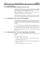
3. From the Program Manager, go to the File menu and selectRun
command.
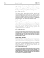
Note
Under Windows 9x, select Run... from the Start button menu. Another
way is to select Start > Settings > Control Panel and on the Control
Panel displayed - Add/Remove Programs.
2-2
Operator’s Guide
DREAM
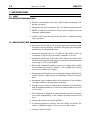
Fig. 2.1
Use command Run
from the File menu of
Program Manager to
start the installation
process
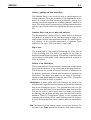
4. Type “a:\setup” in the Run dialog box and press OK button or
use the Browse... button to select the setup.exe file.
Fig. 2.2
Enter the setup.exe
file name and click
the OK button
Note
If you are installing the software from floppy drive b: type in b:\setup
above.
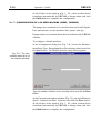
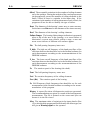
Now you will see the Welcome window of the installation program:
Fig. 2.3
Starting installation
window
DREAM
Chapter 2. Starting Up
2-3
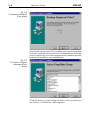
Fig. 2.4
The Select Destination Directory dialog
The dialog provides you with selection of a directory to copy the
software files. To select another directory than the displayed, click
the Browse button. It displays a dialog to explore your disks for path
to a directory to be created.
Fig. 2.5
The Select Sentinel
Directory dialog
If no path to the existing Sentinel directory is displayed, select the
Browse button and find it manually.
2-4
Operator’s Guide
DREAM
Fig. 2.6
The Backup Replaced
Files dialog
Selecting the backup option ('Yes') enables you to revert your system
to the pre-installation state in the case of uninstallation. Although
it may be useful only if no other programs will be installed in period
between the installation and uninstallation.
Fig. 2.7
The Select Program
Manager Group
dialog
Using this dialog, you may change the name of the icon group for
the software or confirm the name displayed.
DREAM
Chapter 2. Starting Up
2-5
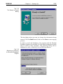
Fig. 2.8
The Ready to Install
dialog
The last dialog where you may yet change the information being
entered. Click the Back button to do it or the Next to start copying
process.
In order to work with databases, the program need the Borland
Database Engine to be installed. It is the shared component which
may be used by many programs. The following dialog will be
displayed to select a directory for the BDE installation.
Fig. 2.9
Selecting a directory
for Borland Database
Engine
2-6
Operator’s Guide
DREAM
After the copying process (illustrated with the process bar) is
completed, the message on it will be displayed.
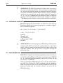
Fig. 2.10
Message on installation completion
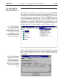
After the installation of DREAM for Sentinel, insert disk labeled
Security into your floppy drive. From the Program Manager, go to
the File menu and select the Run. Type or select by the Browse file
DDINSTAL.EXE.
At the dialog box appeared, press the Express button:
Fig. 2.11
The dialog of the
Security program
DREAM
Chapter 2. Starting Up
2-7
The driver for the hardware protection key to work with Windows
will be installed onto your computer.
After the installation of DREAM for Sentinel, the Setup program
will automatically create a program group 'DREAM for Sentinel'
in the Program Manager and add there two items: 'DREAM' and
'Report Preview'. You can easily drag this items with a mouse to any
program group you prefer.
Fig. 2.12
A program group is
created by the Setup
program
To ensure that DREAM software was installed successfully, attach
the electronic key to the parallel port and try to start DREAM by
double-clicking its icon.
You should see the “DREAM for Sentinel” window with the menu
bar.
Fig. 2.13
The main window of
the DREAM software
before opening the
database
2-8
Operator’s Guide
)
DREAM
ATTENTION! The DREAM application software runs only when it
finds the electronic protection key. The electronic key is supplied with
the software and should be attached to the parallel (printer) interface.
If a printer is already attached to the interface, the key should be
attached to the interface first and the printer should be attached to
the key. The key is transparent to the printer and does not influence
printing. If the program fails to find the key, it displays a message:
"The hardware protection key or security driver needs to be installed."
2.2. TECHNICAL SUPPORT
DREAM software was developed by the VibroTek, Ltd. from St.
Petersburg, Russia. If you have any questions, comments, suggestions or need help, please,
call +7 (812) 327 5563 or fax +7 (812) 324 6547
e-mail: [email protected]
or write:
Vibrotek Ltd.,
140, Stachek pr.,
St. Petersburg, 198207
RUSSIA
)
ATTENTION! The technical support for DREAM is provided for those
customers who filled and sent the registration form to the above
address. When you apply for the support make sure that you know your
registration number that will be sent to you after receiving the
registration form.
2.3. USER INTERFACE
DREAM for Sentinel is a Windows application and we assume you
are familiar with the Microsoft Windows operating system. DREAM
has the standard Windows interface and we will focus on the
peculiarities of DREAM.
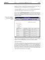
Once you started the DREAM program you see the main window
(see Fig.2.14). Choose the Open command from the DataBase
menu. The program had read the Sentinel database and shows the
plant tree created with the Sentinel software, as well as all the
DREAM menus.
DREAM
Chapter 2. Starting Up
2-9
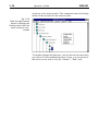
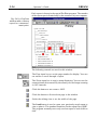
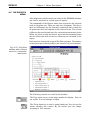
Fig. 2.14
The main window of
the DREAM software
after using the Open
command
To select a node in the plant tree, click it with a left mouse button.
To display the next level in the plant hierarchy, double click the
closed door near a node in the plant tree. To collapse a branch in
the tree, double click an opened door with the left mouse button.
The measurement points have different icons in the plant tree. To
display the condition of the measurement point, double click its
icon with the left mouse button.
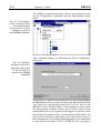
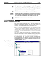
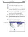
Fig. 2.15
The main window of
the DREAM software
with the Diagnostics
Results dialog box
All operations in DREAM can be made with a selected node in the
plant tree. For example, if you selected a node and issued a report,
the report will be created for the whole branch below this node.
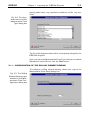
Besides the standard menu bar, you can access several commands
by the floating menu. To access it, click with the right mouse button
2-10
Operator’s Guide
DREAM
anywhere in the main window. The commands from the floating
menu will be executed for the selected node.
Fig. 2.16
Click the right mouse
button to display the
floating menu with the
most common commands
To navigate through the plant tree, you can also use the arrow keys
(up, down). If the expanded plant tree is large, you can go fast to
the end or to the root of it by the <Home>, <End> keys.
DREAM
Chapter 3. Operating the DREAM Program
3-1
3. OPERATING THE DREAM PROGRAM
The DREAM program is used to provide the user of Sentinel the
means for automatic diagnostics and condition prediction of
rotating machinery. The operation with DREAM can be divided
into three main stages: preliminary configuration of DREAM and
Sentinel databases, field measurements and condition diagnostics.
3.1. CONFIGURATION
During its operation DREAM uses two databases: the one of
Sentinel where the names of measurement points, their hierarchy
and corresponding spectra are stored and its own database where
DREAM stores additional parameters of the equipment to be
diagnosed that it needs as an expert system.
The configuration process - it means to set up all the required
parameters of your equipment and measurements - should be done
in both Sentinel and DREAM databases.
First of all make sure that all necessary measurement points are
configured in the Sentinel database. Then, before starting DREAM
exit Sentinel software.
Start DREAM program, choose the Open command from the
DataBase menu. DREAM will open the database of Sentinel and
read all the plants' structure. After this DREAM will display in its
main window the names of all the plants from the Sentinel database:
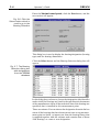
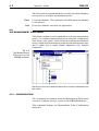
Fig. 3.1. Main window
of the DREAM software with the names
of the plants configured in the Sentinel
database.
To display the names of the areas that belong to a plant, double-click
its name. The same way you can open the units, machines and
measurement points.
3-2
Operator’s Guide
DREAM
To configure a measurement point, select it in the plant tree and
use the Configuration command from the Measurement Point
menu:
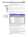
Fig. 3.2. The Configuration command from
the Measurement
Point menu is used to
configure a point in
the DREAM database.
This command displays the Measurement Point Configuration
dialog box.
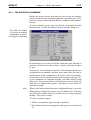
Fig. 3.3. The Measurement Point Configuration dialog box
is used to set up a
point in the DREAM
database
This dialog box contains several pages that can be switched by Next
and Prev buttons. Here you have to choose the Measurement Point
Type from the corresponding drop-down list box, and set the
Maximal Control Period (in days). This parameter is used to plan
the measurement schedule. If there was no defect found in this
measurement point, the program would suggest to measure it next
time in this very number of days, if some defects will be found - this
period will be decreased depending on the types and severities of
the existing defects. For rolling element bearings it is recommended
to state this period equal to 20% of MTBF for this very type of
DREAM
Chapter 3. Operating the DREAM Program
3-3
bearing under these very operation conditions on this very machine.
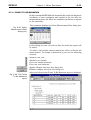
Fig. 3.4. The dropdown list box of the
Measurement Point
Type dialog box
The list of the diagnosed units will be consequently enlarged by the
DREAM designers.
Once you select the Measurement Point Type and type or confirm
Maximum Control Period, click the Next button.
3.1.1. CONFIGURATION OF THE ROLLING ELEMENT BEARING
To configure a rolling element bearing, choose this type in the
Measurement Point Setup dialog box.
Fig. 3.5. The Rolling
Element Bearing type
selected in the Measurement Point Configuration dialog box
3-4
Operator’s Guide
DREAM
Enter the Maximal control period, click the Next button, and the
new section will appear:
Fig. 3.6. Click the
Select button which is
used to go to the
Bearing Selection
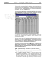
This dialog box is used to display the bearing designation (bearing
type) and the bearing dimensions.
Click the Select button and the Bearing Selection dialog box will
appear:
Fig. 3.7. The Bearing
Selection dialog box
with designations
from the DREAM
database
In this dialog box you have to choose the designation (the identifier
under which the bearings are listed in the specification documents
of the manufacturer where all the technical data of the bearings are
specified) that is installed in this measurement point.
There are variants. You can choose the designation from the list box
where all the bearings that have been entered once in any measurement point are listed, or import one from the bearing library that
is supplied together with the software and contains data of about
5000 bearings, or create a new designation.
DREAM
Chapter 3. Operating the DREAM Program
3-5
To choose the designation from the database - the bearings that were
entered once in a measurement point - click the desired designation
name from the list - the designation will be highlighted and marked
by triangle, and click the OK button.
To choose a bearing from the external bearing library that contains
4000-5000 bearings of mainly Soviet and SKF production, click the
Import button. The following dialog box will appear:
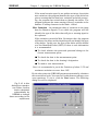
Fig. 3.8. The Bearing
Import dialog box lists
several thousands of
bearing's designations.
Use the Mask text box to find the desired designation. When you
enter the first symbols of the designation, the list advances to the
corresponding names.
You can choose one of the bearings by its designation and verify its
dimensions. Once you click theOK button, this bearing designation
will be included in the DREAM database and will appear in the list
of designations in the Bearing Selection dialog box.
To create a new designation, click the Add button. A blank line will
appear in the list of bearings. Type the parameters of the bearing:
designation ID in the designation column and all other parameters
in corresponding columns:
Din - the diameter of the inner race (or the inner raceway).
Dout - the diameter of the outer race (or the outer raceway, if Din
was the diameter of the inner raceway).
Note: if you do not know the diameters of races you can put in the
cage diameter as a diameter of both inner and outer race. The
program actually needs only the cage diameter that is calculated
as a mean value of inner and outer race diameters. It is also
recommended to enter the cage diameter for the thrust bearings.
3-6
Operator’s Guide
DREAM
Angle - the contact angle in degrees between the rolling elements
and the race.
Drol - the diameter of rolling elements.
Nrol - the number of rolling elements in the bearing.
dNrol - the acceptable variations in the number of rolling elements
set by the operator. During the analysis of the envelope spectrum
the program will correct the number of rolling elements in the
limits Nrol+dNrol, if there is a mistake in the input data. If the
variations in the number of rolling elements exceed +dNrol the
program is not able to identify the type of defect.
Note: Our experience shows that it is rather typical for the bearing
manufacturers to vary the cage design and thus the number of
rollers in the same type of bearing.
After the bearing designation had been selected and confirmed by
the OK button, click the Next button and enter the following
parameters:
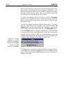
Fig. 3.9. The second
section of the Measurement Point Configuration dialog.
Type the Rotation
Speed and its Variations from measurement to measurement
for this machine.
Rotation Speed - the rotation speed of the bearing can be entered
in Hz.
Variation - possible variations in rotation frequency (fr) from
measurement to measurement.
From the point of the program, the variations could be normal
(set by the operator, for example, Rotation Speed+Variations)
or maximal.
The more variations and maximal variations values the less
certainty (the probability of the exact type of the defect that is
displayed by the program), and it takes more time to make
diagnostics.
DREAM
Chapter 3. Operating the DREAM Program
3-7
If the actual rotation speed is not within variations, but within
max variations, the program identifies the type of the defect but
gives a warning that the data have variations and while processing, the program has revised them to identify the defect. The
program generates the same warning if there is a mistake in the
number of rolling elements in the limits +dNrol.
Max. Variations - the maximum value of variations in the input
data for Rotation Speed (%) at which the program will still
identify the type of the defect but will give a warning signal to
the operator.
If the variations exceed the Max. Variations value, the program
will detect the defect and its depth but will not identify the type
of the defect. In this case, the type of the defect will be defined
as a Not Identified Defect (NID). If there is such information
it is recommended:
To check whether the processed spectrum belongs to the
chosen measurement point
To check the data in the measurement point
To check the data in the bearing’s designation
To make a new measurement.
Note: it is recommended to put in the Variations of about 2-3% and
maximum variations not more than 10%.
By the above data the DREAM program automatically calculates
the severe defect levels. You can view or edit them according to your
own experience. To do it, click the Next button. The following
dialog box will be displayed:
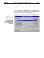
Fig. 3.10. In this
dialog box operator
can either confirm
levels calculated
automatically by
DREAM or change
them according to his
experience
3-8
Operator’s Guide
DREAM
Here are listed all types of defects with actual and default levels. The
defect levels are presented in the percentage of modulation. And
the level for the defect of lubrication is in dB. To change values select
the type of defect and type a new value in the input line under the
list. This way you can edit all the defect levels.
To restore the default values for all defects, click the All default
button; to set a default lever for a certain defect type, select the
defect in the list and click the button next to the level input line with
the default value.
You can also change all defect levels by a certain factor. To do this,
type the change factor in percentage in the input box below All
Default button and click this button. For example, to increase all
defect levels in two times, enter 200% and click All Default button.
Click the Finish button to complete configuration. Now DREAM
is ready to receive spectra for diagnostics, but it has to get spectra
from the Sentinel database. After a new measurement point was
configured or a setup for an old measurement point was significantly
changed, DREAM displays the following dialog box:
Fig. 3.11. To read
spectra for a newly
configured measurement point, DREAM
needs to reread
Sentinel's database
Click Yes button to reread new spectra from the Sentinel database
or click No to proceed with configuration. If you click No, the new
spectra will be accessible by DREAM when you will close and open
database next time.
DREAM
Chapter 3. Operating the DREAM Program
3-9
3.1.2. CONFIGURATION
OF THE ROLLING ELEMENT BEARING AND GEARBOX
If you have to configure a rolling element bearing of gearbox,
choose this option in the Measurement Point Configuration dialog
box and confirm it by the Next button.
Fig. 3.12. The starting
window of the Configuration dialog for
choosing the Measurement Point Type
After clicking the Select button at the intermediate window (which
is appeared) and choosing a bearing designation at the Bearing
Selection window (more detailed description of these operations
you can get in previous section 3.1.1. Configuration of Rolling
Element Bearing), which one you confirm by clicking the OK
button, the intermediate window appears again with inputted
parameters of the chosen bearing.
Click the Next button, and the gearbox configuration window
should be present.
Fig. 3.13. The Measurement Point Configuration dialog box
in which there is the
drop-down list box of
gearbox types yet
configured.
3-10
Operator’s Guide
DREAM
If there are no gearbox types configured by you, the list is empty
and the gearbox scheme is absent. You must choose the Gearbox
Specification via clicking the New button.
Fig. 3.14. The Gearbox Specification
dialog box
Moving through input boxes in turn by striking the Tab key or
mouse-button-clicking, you must name the gearbox type that you
are setting at the Type box, type axes number in the Axes box and
teeth number in the Teeth boxes column. Each gear has its own
combined number. The first figure indicates the number of the axis
on which the gear is placed, the second figure indicates the number
of the axis on which the connecting gear is placed. For example,
Z12 is the gear placed on the first axis (input shaft) and connecting
to a gear placed on the second axis.
To complete the gearbox specification, click the OK button.
You will be back to the gearbox configuration window. To change
or delete the gearbox type, use relative buttons (Change, Delete).
Note:
If the certain gearbox type used yet for the several measurement points,
you can not delete that type at once. First, you have to know all the
measurement point with that type configured, by means of the Statistics
command from the Report menu. Then you have to delete all data from
them by the Delete Data command from the Measurement Point menu.
Only after that you can delete an improper type in the gearbox
configuration window.
Here you have to put in all the frequency parameters: "First axis
rotation frequency", "Rotation frequency variation" and may be
"Maximum Variation" (more detailed description of these param-
DREAM
Chapter 3. Operating the DREAM Program
3-11
eters you can get in the previous section 3.1.1. Configuration of the
Rolling Element Bearing). Click the Next button to confirm all the
inputted data.
The last section of the Measurement Point Configuration, the
defect levels window, should appear. The last configuration step is
the same as for the rolling element bearing. Refer to it.
This way you can configure the DREAM database for all the
measurement points that were created in the Sentinel software.
Fig. 3.15. In this
dialog box operator
can either confirm
levels calculated
automatically by
DREAM or change
them according to his
experience
3-12
Operator’s Guide
DREAM
3.1.3. CONFIGURATION
OF THE ROLLING ELEMENT BEARING AND SHAFT LINE
Configure this measurement point type the same way as the rolling
element bearing. Choose only the Rolling element bearing and Shaft
Line on the first stage of configuration (Fig. 3.4).
There are differences in the defect list on the last stage of
configuration in regard to the shaft coupling.
This measurement point type is required not only the envelope
spectra (as for the rolling element bearing) but autospectra as well.
3.1.4. CONFIGURATION OF THE FLUID FILM BEARING
Configuration of the fluid film bearing is done the same way as for
the rolling element bearing excluding the bearing selection which
is absent. The list of the defects that can be indicated differs,
certainly.
So, refer to Configuration of the Rolling Element Bearing section.
For configuration of the fluid film bearing, the following windows
are used: the bearing type selection window (Fig. 3.4), the
frequency parameters window (Fig. 3.9), the defect levels window
(Fig. 3.10).
3.1.5. CONFIGURATION OF THE FLUID FILM BEARING AND GEARBOX
In addition to the Fluid Film configuration you must specify the
gearbox.
To configure a point of this type 1. Select the Fluid Film and Gearbox in the first section of the
configuration dialog (Fig. 3.4).
2. Select or specify the gearbox type as well as frequency parameters
(Fig. 3.13, 3.14).
3. Set up or confirm defect levels (Fig. 3.10).
DREAM
Chapter 3. Operating the DREAM Program
3-13
3.1.6. CONFIGURATION OF AN ELECTRIC MACHINE (INDUCTION MOTOR,
SYNCHRONOUS MACHINE)
At the Configuration dialog box (Fig. 3.4), choose the Measurement Point Type - Induction Motor or Synchronous Machine, and
click the Next button.
At the Frequency parameters window (Fig. 3.9), put in the Rotation
Speed, Variation and Max. Variation and click the Next button.
The Electric Machine Setup section appears:
Fig. 3.16. The Electric
Machine section of
configuration.
Put in Mains Power Supply in Hz and
Number of slots
Number of slots in the rotor (for induction
motor) - number of bars (rods) for the squirrel cage type rotors
or the number of slots for the phase type rotors. Number of slots
in the stator (for synchronous machine).
Note:If you do not know the actual number of slots, in the majority
cases you can define this number by the analysis of autospectrum
of electric machine body vibration. To do this look for the slot
passing frequency and divide it by the rotation speed.
Point for Tangential Measurements Choose a measurement
point in which you will store the tangential measurements
results. In this case the current machine should contain additional point not configured in DREAM. Choose a point for
tangential measurements from the list box. If there are no
additional points configured in DREAM for the current machine, DREAM will present an error message and the electric
machine would not be configured.
Click the Next button.
3-14
Operator’s Guide
DREAM
At the Defect levels window (Fig. 3. 10), either confirm levels
(calculated automatically by DREAM) or change them, and click
the Finish button to complete the configuration.
3.1.7. CONFIGURATION OF A BLADED MACHINE (PUMP, TURBINE)
The pumps are considered to be a machine that works with liquids.
Fans and turbines are the machines that operate with gas.
Pumps can have a cavitation defect that can be detected by DREAM
software.
To configure a bladed machine:
At the Configuration dialog box (Fig. 3.4), choose the Measurement Point Type - Pump Impeller or Fan (turbine) wheel, and click
the Next button. The Bladed machine setup dialog appears:
Fig. 3.17. The specialized dialog box for
the bladed machine.
Type the number of blades on the working wheel and click theNext
button.
At the Frequency parameters window (Fig. 3.9), put in the Rotation
Speed, Variation and Max. Variation and click the Next button.
At the Defect levels window (Fig. 3. 10), either confirm levels
(calculated automatically by DREAM) or change them, and click
the Finish button to complete the configuration.
DREAM
Chapter 3. Operating the DREAM Program
3-15
3.2. SETTING UP
MEASUREMENTS
According to the configuration data of measurement points DREAM
will require to set up the measurements in the appropriate way. This
should be done in the Sentinel database. Preliminarily, you can issue
a list of the measurement setups required for DREAM diagnostics
on all measurement points, have a look at them and set up
measurements for the points in Sentinel according to this list. For
that purpose, select in the DREAM software a machine or a unit
to which the measurement points to be configured belong and use
the Measurement Setups command from the Reports menu:
Fig. 3.18. The Measurement Setups
command from the
Reports menu is used
to issue the list of
settings to set up
measurements in the
Sentinel database
There is also the Setup command in the Measurement Point menu
(and in the floating menu as well). This command presents the
Measurement Setup information box (for a single measurement
point only):
Fig. 3.19. The Setup
command from the
floating menu presents the Measurement Setup information box (for a single
measurement point
only)
3-16
Operator’s Guide
DREAM
In this dialog box there can be one or the two sections - for
envelope and auto- spectrum. Click the title of a section to see
it.
Fig. 3.20. The Measurement Setup with
the selected
Autospectrum section.
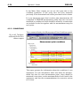
The Status column may contain the letters: L, R, A.
L - leading spectrum that is presented in reports,
R - required spectrum,
A - additional spectrum.
Fig. 3.21. The Measurement Setup
information box with
the Autospectrum
section visible.
Type can be Baseband or Zoom to be set in the Sentinel
measurement setup.
Note:
Due to the fact that Type 2526 data collector can measure only 400
lines resolution spectra in some cases DREAM will require to measure
two spectra with different settings for diagnostics (for example a bearing
with a number of balls more than a hundred). For DREAM these two
spectra are both one measurement and it will identify this measurement
by a time of the leading spectrum. So, for diagnostics DREAM needs
leading and required spectra to be measured, additional spectra may
be used to refine some types of defects, but not required. Leading
DREAM
Chapter 3. Operating the DREAM Program
3-17
spectra are used to identify the measurement and only the date of
leading spectrum is presented in all reports and lists.
The button OK lets you come back to the DREAM main window.
The other parameters contains also in the report.
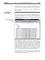
We return to the Measurement Setups command from the Reports
menu. The program automatically issues the list that contains
required setup parameters for all measurement points in the chosen
machine or unit.
Fig. 3.22. The Measurement Setups
report
The report can be printed or saved by clicking the corresponding
buttons. Click the Exit button to close the report window.
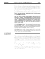
Now start Sentinel.
The task is to change the setup for all measurement points that will
be used for diagnostics by DREAM. To do it, choose machine in
the plant tree of Sentinel software and enter the Measurement
Setup. We will discuss indetailes the Envelope Spectrum dialog box
for envelope spectrum measurement of the corresponding point.
The settings for autospectra are similar.
3-18
Operator’s Guide
DREAM
Fig. 3.23. Measurement Setup: Envelope
Spectrum dialog box
is used to setup
envelope spectrum
measurement in the
Sentinel database
Here set for each measurement point:
Averages - Number of averages should be in the range 16-30. The
more averages you select the more reliable results in diagnostics
you receive, but the measurements will take more time.
Averaging Mode - Set to Spectrum.
Weighting Mode - Set to Hanging.
Trigger - Set to Free Run.
Detector - Set to RMS.
Integrations - Set to None.
Frequency Mode - Set to Absolute.
Frequency Span - Set as required by DREAM in the Fs column
in the Measurement Setup list for this measurement point.
Lower Frequency - Set as recommended by DREAM in the Flow
column in the Measurement Setup list for this measurement
point.
Upper Frequency- Set as recommended by DREAM in the F_high
column in the Measurement Setup list for this measurement
point.
All other parameters are not essential for DREAM but, of course,
you should set a proper gain factor.
The choice of Lower and Upper frequency (thus the bandpass filter
for envelope detector) is a very important factor. The DREAM only
recommends a 1/3 octave band, but the choice of the actual band
should be done after the analysis of the autospectrum in this point.
The detailed description of how to choose that frequency band for
the envelope analysis can be found in the third part of this manual,
but the basic rule says: look at the shape of the autospectrum in the
region of the recommended bandpass filter. If there are some
DREAM
Chapter 3. Operating the DREAM Program
3-19
resonances or strong harmonic components, it is recommended to
set the bandpass filter to the nearest flat region of the autospectrum.
This way you have to configure all points for DREAM in the
Sentinel database.
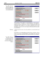
3.3. GETTING
ROUTE MAPS
Once measurement points are configured, DREAM can form a list
of bearings to be measured. To do it, select a node on the plant tree
in DREAM and choose the Points To Be Measured command from
the Reports menu.
Fig. 3.24. The Points
To Be Measured
report
When DREAM will diagnose some spectra, it will give either a
recommendation on some corrective actions to be done for the unit
or give a non failure operation period prediction. Then DREAM
will automatically follow up the conditions of your equipment and
include in the list only the measurement points for which the
condition prediction is expired according to the day you chosen.
In the Meas. Date column you can see the expiry date of the
condition prediction. If this point have not been measured previously, "Not determined" will be presented in this column.
Once you've got the list of measurement points to be measured, you
can go to Sentinel and form a corresponding route and download
it to the Type 2526 data collector.
3-20
Operator’s Guide
DREAM
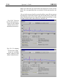
3.4. COLLECTING
AND PROCESSING DATA
The vibration data are collected by the Type 2526 data collector
according to the routes formed and loaded through the Sentinel
software. After measurements, unload the routes from the data
collector into the Sentinel database.
To process data by DREAM, exit Sentinel and start DREAM. In
the plant tree choose unit, machine or point for data processing and
select the Diagnose command from the Spectra menu:
Fig. 3.25. The Diagnose command from
the Spectra menu
The command is used to diagnose spectra and store results of
diagnostics in the DREAM database.
Note: the higher level you choose the more measurement points you can
diagnose (but not higher than the machine group).
By this command the Diagnose New Spectra dialog box is
displayed:
Fig. 3.26. In the
Diagnose New Spectra dialog box you
can choose a spectrum from the Sentinel database for
processing with
DREAM
DREAM
Chapter 3. Operating the DREAM Program
3-21
If in the plant tree you have chosen a machine group node, you can
choose a machine from the list of machines for diagnostics. If you
have chosen a machine or a measurement point, you can choose
only a measurement point and a spectrum.
In this dialog box you can choose one by one all the spectra for the
points below the selected node and process them in turn.
Choose Machine if possible, Measurement point, Spectrum. Enter
or confirm Rotation Speed.
Only new spectra from the Sentinel database, that have not been
processed by DREAM, are included in the list of spectra when the
New Only box is checked. In another way you can process the old
spectra. To diagnose all previous spectra to see the defect development from measurement to measurement, check the History
check box. In the last case much more time may be needed to
process all the spectra.
Click the Diagnose button. The spectrum will be processed automatically and the results of diagnostics displayed in the Detailed
Diagnostics dialog box (see the next section Detailed Diagnostic).
Use scroll bar to check all the defects in the list.
Click Done button, and the diagnostic results will be saved in the
DREAM database for future reporting. This way you can process
all new spectra from the Sentinel database.
3.5. DETAILED
DIAGNOSTICS
This mode is an optional utility that displays you the diagnostic
process and explains why the DREAM says that this type of defect
is found in the measurement point and why this or that recommendation is given. In other words, it provides an operator with all
available data to make a correct decision about the condition of the
unit.
The starting point for this mode is the Detailed Diagnostics dialog
box that appears on the screen as the result of diagnostics for any
spectrum (see Fig. 3.25).
The dialog box contains three fields: a list of defects, date of the next
measurement (prediction of the non-failure operation period) and
a list of recommendations.
3-22
Operator’s Guide
DREAM
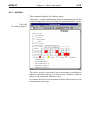
Fig. 3.27. The Detailed Diagnostic
dialog box with the
list of defects and
recommendations
The severity of the defects is represented by a color (green incipient, yellow - medium, red - severe). Besides, for each defect
found the program presents its severity in modulation index and
probability for a defect to be of this particular type (in the
parentheses). Please, refer to the 4th part of this manual for the table
of probabilities.
Warning
A defect may be not seen. Use the scroll bar to view the whole list of
defects.
Each defect or recommendation of the list has a check box. If you
check a box near a recommendation, the program will check the
boxes near the defects that were the reasons for this very recommendation.
Fig. 3.28. Check a
check box of the
recommendation to
see the reason for
this very recommendation
DREAM
Chapter 3. Operating the DREAM Program
3-23
In the right part of this dialog box there are three buttons (which
function is described more detailed in the next sections):
Done
Saves the results of diagnostics in the database and closes Detailed
Diagnostics dialog box.
Details
Displays you the spectrum with all lines and the defects found. In
this mode DREAM can display you the diagnostic symptoms for
each defect or recommendation.
Expertise
Displays the expertise of the spectrum including all recommendations with reasons for them, all the defects with their reasons, all
warnings or comments in the text form.
3.5.1. DETAILS
Click the Details button in the Detailed Diagnostics dialog box to
get this mode. Before you can check on the defect or recommendation you are interested in from the corresponding list. The
following window will be displayed:
Fig. 3.29. The results
of diagnostics are
presented in this
window together with
the spectrum, frequencies and modulation indexes of lines
found in the envelope
spectrum and their
identification
The Diagnosis dialog box contains three fields. You can change the
size and shape of each window by dragging field separators. The first
window presented a spectrum. In the second window all lines found
in the spectrum are presented and classified by their origin. For
example,Frot is the rotation speed,Fout and Finare the ball passing
frequencies on outer and inner races, etc. In the third window you
can see all the defects found in the bearing.
3-24
Operator’s Guide
DREAM
When you check on any check boxes for frequencies in the second
field, the corresponding lines are marked in the spectrum by red
lines.
If you check on any check box near the defect, you will see reasons
for diagnosis: in the first window you will see the lines by which the
defect had been found, the lines will be marked by red lines; in the
second window these lines will been checked on.
Fig. 3.30. To find a
line in the spectrum,
check on the check
boxes of the corresponding frequency.
Fig. 3.31. To display
all the lines symptoms for a certain
defect, check on the
defect check boxes.
DREAM
Chapter 3. Operating the DREAM Program
3-25
The menu of the Details window contains the following commands:
Envelope
Displays diagnosis by the envelope spectrum. This command
equals to the Envelope button from the speed bar.
Envelope History
Displays diagnosis by the envelope spectrum history. This command equals to theEnv. Historybutton from the speed bar. It would
be disabled if you measured only one spectrum for this measurement point or checked off the History check box in the Diagnose
New Spectra dialog box. The command allows you to display a
diagnosis for the previous spectra, compare two spectra and see how
the defect has developed (do it by clicking the Envelope and Env.
History buttons in turn).
Direct
Displays diagnosis by the autospectrum. This command equals to
the Direct button in the speed bar. This command is disabled for
the measurement points that do not require autospectra for
diagnostics, e.g. for rolling element bearings.
Direct History
Displays diagnosis by the autospectra history. This command
equals to the Dir. History button in the speed bar. This command
is disabled for the measurement points that do not require autospectra for diagnostics, e.g. for the rolling element bearings.
Close
Closes this window.
Fig. 3.32. The Diagnosis menu with the
pop-up line at the
bottom of the dialog
box
Results of diagnostic you can easily require in the main window of
DREAM. To do it, select the measurement point and double-click
it with the left mouse button.
3-26
Operator’s Guide
DREAM
Fig. 3.33. The Diagnostics results box
with the list of defects
You can get this box also by the Last Results command from the
Measurement Point menu.
3.5.2. EXPERTISE
Click the Expertise button in the Detailed Diagnostics dialog box
to get the expert estimation of the spectrum, recommendations and
all defects and their symptoms together with the warnings and
comments. By this command the following window will be displayed:
Fig. 3.34. The expert
estimation of the
spectrum includes
recommendations
with the reasons for
them, all defects and
their symptoms together with the possible warnings and
comments
DREAM
Chapter 3. Operating the DREAM Program
3-27
3.6. ANALYSIS
Besides data processing in automatic mode described above
DREAM has detailed analysis mode for all spectra stored in the
database. To access it, choose point in the plant tree in DREAM
and choose the Analysis command from the Measurement Point
menu.
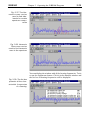
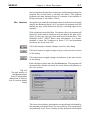
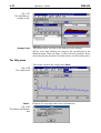
By this command the Spectra Display window is displayed :
Fig. 3.35. The main
window of PLOT
program that is used
for the analysis and
diagnostics of spectra
within DREAM software
The window of the plot program contains the Analysis window
where the spectra are displayed, the Date that allows you to choose
spectra for displaying and analysis, the Section that displays the
history of certain spectra component's development from measurement to measurement, and 3-D Plot that displays the 3-d surface
representation of the spectra development in period from measurement to measurement.
The choice of spectra for displaying can be done in the Date
window. Click the certain date to toggle display/hide for a
corresponding spectrum. You can trend spectra by displaying them
all together at the Analysis window.
The cursor can be placed anywhere in the Analysis window by
clicking the mouse button in the desired location or it can be moved
by cursor keys or by pressing the
buttons in the speed bar. The
position of the cursor and its amplitude readouts are displayed in
the speed bar of the main window. The color of the spectrum
coincides with the color square near the date and color of the cursor
readout.
3-28
Operator’s Guide
DREAM
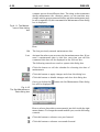
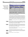
Synchronous to the movement of the cursor in the Analysis window,
the section in the Section window changes (the horizontal axis here
represents the intervals between spectra measurements and the
vertical axis - amplitude of the spectra at the position of the cursor
in the Analysis window) and the cursor moves in the 3-D Plot
window.
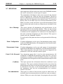
Fig. 3.36. The cursor
is controlled in the
Analysis window,
synchronously it
moves in the 3D-Plot
window, in the Section window you can
see trends on the
spectra components
at the cursor position.
Besides the normal cursor you can display two harmonic cursors.
One is called Harmonics and can contain both harmonics and
sidebands, another is called Harmonic Row and can contain only
harmonics. The number of harmonics in these cursors and number
of side bands and modulation frequency for the Harmonics cursor
are controlled by the Harmonics command from the Options menu.
To display harmonic cursors, use corresponding commands from
the View menu, or click the following buttons on the speed bar:
to display Harmonics cursor;
to display Harmonic Row.
Buttons are used to move Harmonic cursor.
Alt +
buttons are used to move Harmonic Row cursor .
DREAM
Chapter 3. Operating the DREAM Program
3-29
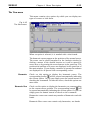
Fig. 3.37. The Harmonics cursor can be
used to find sidebands for certain
spectrum components
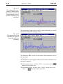
Fig. 3.38. Harmonic
Row cursor can be
used to find harmonic
rows in the spectrum
You can display the window with all the bearing frequencies. To do
so use the right mouse button. Click it in the Analysis window and
the list box of bearing frequencies will be displayed.
Fig. 3.39. The list box
presents all the characteristic frequencies
of a bearing.
3-30
Operator’s Guide
DREAM
To move cursor to the frequency position in the Analysis window,
click the frequency you are interested in.
To create a report in a standard text editor with any pictures from
the Spectra Display window, you can copy into clipboard contents
of any window. Two commands from the Graphs menu can be used
to do it. These are Copy and Copy to commands.
Fig. 3.40. The Graphs
menu for printing and
copying graphics.
Besides, you can immediately print the contents of the active
window using the Print or Print Preview commands. The graph will
be stretched to the paper size and orientation of the default printer.
To change these parameters use the Printer Setup command.
Attention!
If you try to run more than one Spectra Display, you will fail. You must
find Spectra Display yet opened, close it, and run again for the new
selected node.
DREAM
Chapter 3. Operating the DREAM Program
3-31
3.7. REPORTING
After diagnostics all the results are stored in the DREAM database
and can be retrieved in several types of reports:
The commands of the Report menu issue reports for the selected
node in the plant tree. There are only two exceptions. The first is
the List of Bearings (by the Statistics command) that is made for all
plants and does not depend on the selected node. The second is
History that can be made only for a selected measurement point.
When you select a node and issue a report all measurement points
that are below this node in the tree hierarchy are included in the
report.
List of Bearings
This report presents all designations and specifications of the
bearings included in the bearing database. These are the bearings
that you have on your plant at any measurement point. This report
is issued for all the equipment. Its contents are not depending on
the node or bearing designation you have selected. This report is
created with the command Statistics.
For each node of the plant tree there can be generated the following
reports:
Points' Configuration
Contains information on the type of measurement points configured in the DREAM database, the designation of the installed units,
the rotation speed.
Measurement Setups
Contains information on the type and setups of measurements
required by DREAM for the diagnostics of all measurement points.
These setups depend on the type of the unit to be diagnosed, the
parameters of the unit and the rotation speed.
Points To Be Measured Very important report that is used to plan measurements. All
configured in DREAM measurement points that have not been
measured or condition of which should be refined by a certain date
are included in the list together with the measurement setup for each
point.
Conditions
This report presents the information about the condition of your
equipment. The report contains information when were done the
measurements last time for each measurement point, when should
be measured it next time, on the maximum defect level found in
the equipment, and lists the recommendations for corrective
actions to be done.
Recommendations
This report is a subset of the previous report in which there are
included only the measurement points that have some recommendations. When you create this report, the program asks you which
3-32
Operator’s Guide
DREAM
of recommendations to include in the list. The possible recommendations are:
Refine the defect type - it means that a defect is found but the
type of it can not be determined, actually it may be not the
defect of a bearing, for example, but an interference from
other units;
Check the lubrication quality - the defect of lubrication was
detected that usually results in the increase of the high
frequency vibration level.
Replace the bearing - dangerous combination of defects
occur. This recommendation is given when the system
considers that in the next 1% of MTBF 10% of the bearings
in such a condition may fail.
Correct misalignment - it means that the mounting defect of
the bearing was found - the misalignment of inner and
outer races. This is not a very dangerous defect that leads
to the immediate failure of the bearing, but it significantly
decreases the service life of the bearing.
Correct nonuniform radial tension - it means that the mounting defect of the bearing was found - the nonuniform
clearances. This is not a very dangerous defect that
normally does not lead to immediate failure of the bearing,
but it may significantly decrease the service life of the
bearing.
For each measurement point there can be shown the
History
Contains information of all measurements and the results of
diagnostics that were made for this measurement point.
To issue a report, choose a node in the plant tree and use the
corresponding command from the Reports menu.
Fig. 3.41. The Reports menu
DREAM
Chapter 3. Operating the DREAM Program
3-33
Besides the reports on the selected node you can get the statistics
reports on the selected bearing designation or gearbox type. They
are List of Bearings, Measurement Points, Conditions, Recommendations.
To issue a statistic report, select the Statistics command from the
Report menu. It calls the Statistic Report Settings dialog box.
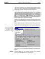
Fig. 3.42. The dialog
to choose a bearing
designation or gearbox type for reporting
By this dialog box you can choose the component type (bearing or
gearbox) you want to issue a report, and type of report as well.
You can see in this dialog box the list of the bearings (gearboxes)
used, and how many times they are used. It can be useful, for
example, if you want to know whether you need the bearing of this
type. Or, if you configured an improper bearing, and that caused
wrong diagnostics, you need to know in which points it is used,
delete the data and reconfigure these points. Only then you can
delete the improper bearing.
Note:
When to find points with the improper configured bearing, you use the
Measurement Configuration report, select the highest level. Only then
you find all the similar points. In another way you can get program
message "The report is empty".
Here 1. Select a component type (bearing or gearbox).
2. Select from the list the bearing/gearbox type you are interested
in.
3. Select a type of the statistic report.
Confirm your choice by the OK button or escape this dialog by the
Cancel button.
3-34
Operator’s Guide
DREAM
Each report is shown in the special PrePrint program. The number
of the report open is limited only by the resources of your computer.
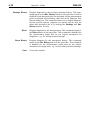
Fig. 3.43. A PrePrint
window with a History
report for a measurement point.
The following controls are used in this window:
The Page input box to set the page number for display. You can
use arrows to scroll through a report.
The Zoom input box is used to setup displaying. You can use the
arrows advance this control. By the arrows you can change zooming
in 10% intervals.
Click this button to set zoom to 100%.
Click this button to fit the whole page in the window.
Scales the editing view to see the width of the page.
The Load button is used to open your previously saved report to
view or print it. The standard extension for the report files is QRP.
The program normally saves only one last report of each kind on
disk.
DREAM
Chapter 3. Operating the DREAM Program
3-35
The Save button is used to save a report on disk. The standard
extension for the report files is QRP. The program normally saves
only one last report of each kind on disk, so to be able to open and
print reports later you have to save them manually.
Click this button to print a report on the default printer.
When this check box is checked on, the Print dialog box is displayed
before setting the report to printer. In this dialog box you can setup
your printer, set the print range, the number of copies, etc.
The Exit button is used to close this window.
3.8. RECOMMENDED
MODE OF PROGRAM OPERATION
Here we will discuss an optimum way of DREAM operation once
you have configured you database and how use the system as a
condition monitoring and predictive maintenance tool.
First of all when you come to your office, you can issue the Points
To Be Measured report for the whole equipment for today or for
any later time, e.g. by the next Monday if you are not going to work
on weekend. You can analyze the amount of work to be done during
this period.
Next you set up the corresponding route in the Sentinel software,
load it into the 2526 data collector, make measurements and unload
them into Sentinel. Then exit Sentinel and start DREAM.
In DREAM select one by one all the units from which the
measurement points were measured. Once you selected a unit click
the right mouse button to display the floating menu and select the
Diagnose command from it.
Fig. 3.44. The floating
menu is the most
convenient way to
work with the plant
tree. It is simply
accessed by the right
mouse button
3-36
Operator’s Guide
DREAM
In the DREAM main window you can get an additional menu which
contains the main commands. To do it select any element of the
plant tree and click the right mouse button.
The Diagnose New Spectra dialog box will be displayed. Check on
the New Only check box, select one by one all machines and
measurement points from the lists and diagnose all the new spectra.
In case of doubts in diagnostics you can use the Details and
Expertise modes to confirm the diagnosis.
After you finished with one unit, select another one in the plant tree
and process all spectra.
When you have processed all new spectra it is worth creating new
reports: Conditions to print the updated report on condition of your
equipment with the dates of the next measurements, it can help you
to optimize orders for the spare parts, so that you minimize the stock
and have enough time to order only the needed ones in advance;
andRecommendationsto plan the maintenance works. You can print
separate reports for "Bearings To Be Replaced" by including only
this recommendation in the list, "Bearings To Check the Lubrication" or "Bearings With Mounting Defects" by including in the list
only some of recommendations. This can be rather helpful when
different persons are responsible for certain corrective actions.
Sometimes it may be worth printing the Bearing History reports to
make a decision whether to replace a bearing or not. Usually,
DREAM recommends to make only 5-7 measurements during the
bearing service life, and you can see how the defects change and
develop within a bearing. Typical situation is when first a small wear
of, say the outer race, develops, then in half a year it transforms in
medium cavities on the same race, then in 1-3 months it changes
up to severe cavities and medium wear of the same race and some
medium defects on another one, and in this case you have to be
more careful and measure more often. As soon as another severe
defect develops - cavities on the inner race or rolling elements (this
usually happens after another 2 weeks - 2 months) DREAM
recommends to replace the bearing.
DREAM
Chapter 4. Menu Description
4-1
4. MENU DESCRIPTION
This chapter of the manual will describes all the commands and
features of the DREAM software.
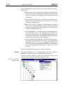
4.2.
THE DATABASE MENU
This menu is used to work with database.
Fig. 4.1
Menu Database of
the DREAM software
The following commands are included in the menu:
Open
Opens the database of Sentinel and reads all plants' structure and
spectra that can be used by DREAM for diagnostics.
Note:
To start DREAM and open the database of Sentinel, you should exit
Sentinel. Otherwise this command will be disabled. When DREAM
reads all the spectra it closes the Sentinel database and you can work
simultaneously with Sentinel and DREAM.
View
This command can be executed independent on the database of
Sentinel being opened. By this command DREAM 1. Opens its database in the same state as it was closed last time.
In this case new spectra from the Sentinel database can not be
used.
2. Displays in the DREAM plant tree only the measurement
points configured in DREAM. The tree branches that do not
contain such points are not present at all.
3. The measurement points configuration command is disabled,
but all other commands including reports, diagnostics, analysis
work as in normal mode.
4-2
Operator’s Guide
DREAM
The View mode is recommended when you do not need to diagnose
new spectra or configure measurement points.
Close
Exit
Closes the database. The command is disabled when the database
is not opened.
Closes the database and quits the application.
4.3.
THE MEASUREMENT POINT MENU
This menu contains several commands to work with measurement
points - to configure measurement points (and edit configuration
data: delete, copy, paste) , enter and retrieve information about the
setup, condition of measurement points and last maintenance date;
also it enable you to make manual diagnostics (the Analysis
command).
Fig. 4.2
The Measurement
Point menu of the
DREAM software
Below you can see a detailed description of each command from
this menu.
4.3.1. CONFIGURATION
The Configuration command from the Measurement Point menu
is used to configure (set up) a point in the DREAM database.
This command displays the Measurement Point Configuration
dialog box:
DREAM
Chapter 4. Menu Description
4-3
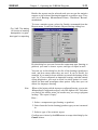
Fig. 4.3
Measurement Point
Configuration dialog
box is used to set up
a point in the DREAM
database
This dialog box contains three sections that can be switched by the
Next and Prev buttons. The first section have the following
controls:
Measurement Point Type A list box where you have to choose one of the measurement point
types from the list. Click the button to open the list.
Maximal Control Period An input box. Enter the period in days that will be an interval
between measurements for a measurement point that has no
defects according to the last diagnostic results. For rolling element
bearings we recommend to enter 20% of MTBF.
Click this button to disable changes and close this dialog box
Click this button to apply changes and advance to the next section
of the dialog box
The following, for example, is the rolling element bearing configuration. Click the Next button to advance to the next section:
Fig. 4.4
The second section
of the Measurement
Point Configuration
dialog is used to
select a bearing
designation
4-4
Operator’s Guide
DREAM
The second section displays information about the bearing designation and has the following controls:
Click this button to choose a designation from the database or enter
a new one
Click this button to disable changes and close this dialog box
Click this button to apply changes and go to the previous section
of this dialog
Click this button to apply changes and advance to the next section
of this dialog box
When you click the Select button the Choose a Bearing dialog box
will be displayed on the screen:
Fig. 4.5
Bearing Selection
dialog box is used to
work with the database of bearings'
designations
This dialog box lists all the bearings' designations that were used for
any measurement points previously. To select a bearing, click a
desired row. To change a bearing parameters, simply click a
parameter to be changes and enter the new value.
The following abbreviations are used in the list:
Din - the diameter of the inner race (or the inner raceway).
Dout - the diameter of the outer race (or the outer raceway, if Din
was the diameter of the inner raceway).
Note: if you do not know the diameters of races you can enter the cage
diameter as a diameter of both inner and outer race. The program
actually needs only the cage diameter that is calculated as a mean
value of inner and outer race diameters.
Angle - the contact angle in degrees between the rolling elements
and the race.
DREAM
Chapter 4. Menu Description
4-5
Drol - the diameter of rolling elements.
Nrol - the number of rolling elements in the bearing.
dNrol - the acceptable variations in the number of rolling elements
set by the operator. When analyzing the envelope spectrum, the
program will correct the number of rolling elements in the limits
Nrol+dNrol if there is a mistake in the input data. If the
variations in the number of rolling elements exceed +dNrol, the
program is not able to identify the type of defect.
Note: Our experience shows that it is rather typical for the bearing
manufacturers to vary the cage design and thus the number of
rollers in the same type of bearing.
This dialog box has the following controls:
Click this button to add a blank line to the list where you can fill
in the designation and dimensions of the new bearing
Click this button to access the bearing library that is supplied with
the DREAM software and contains 4000-5000 bearing designations from different manufacturers
Click this button to delete a selected bearing from the database
Click this button to choose a selected designation for the measurement point and close this dialog
Click this button to disable your selection and close this dialog
When you click the Import button, the Import a Bearing dialog box
will be displayed.
Fig. 4.6
Import a Bearing
dialog box is used to
work with the external
library of bearings'
designations
4-6
Operator’s Guide
DREAM
This dialog box lists bearings' designations from the external bearing
library. To make a choice, select the desired bearing and click the
OK button.
This dialog box has the following controls:
A text box that is used to find the desired designation. When you
enter the first symbols of the designation, the list advances to the
corresponding names.
Click this button to accept choice and add the selected designation
to the DREAM database and close the dialog box.
Click this button to disable your choice and close the dialog box.
Once you click the Next button at the second section of the
Measurement Point Configuration dialog box, you advance to the
next section:
Fig. 4.7
The third section of
the Measurement
Point Configuration
dialog box is used to
enter the parameters
of the rotation speed
The third section has the following controls:
Rotation Speed
Variation
An input box to enter the rotation speed of the machine in Hz.
An input box to enter possible variations in rotation frequency from
measurement to measurement.
From the point of the program the variations could be normal (set
by the operator, for example, Rotation Speed+Variations) or Max
Variation.
The more Variations and Max Variations are, the less the certainty
(the probability of the exact type of the defect that is displayed by
the program) and it takes more time to make the diagnostics.
If the actual rotation speed is not within Variations, but within Max
Variations, the program identifies the type of the defect but gives
DREAM
Chapter 4. Menu Description
4-7
the warning that the data have variations, and during processing the
program has revised them to identify the defect. The program
generates the same warning if there is a mistake in the number of
rolling elements in the limits +dNrol.
Max. Variations
An input box to enter the maximum value of variations in the input
data for the Rotation Speed ( in %) at which the program will still
identify the type of the defect but will give a warning signal to the
operator.
If the variations exceed the Max. Variations value, the program will
detect the defect and its depth but will not identify the type of the
defect. In this case, the type of the defect will be defined as a "Not
identified defect" (NID). When such information, it is recommended to enter the Variations of about 2-3% and maximum
variations not more than 10%.
Click this button to disable changes and close this dialog
Click this button to apply changes and go to the previous section
of this dialog
Click this button to apply changes and advance to the next section
of this dialog
Enter the above values and click the Next button. The program will
automatically calculate the levels for severe defects and advance to
the next section:
Fig. 4.8
The last section of
the Measurement
Point Configuration
dialog box is used to
set or confirm defect
levels
The last section displays information on the default (calculated by
the program) and actual levels for severe defects. The actual levels
are presented in the Level column and the default in the Default
4-8
Operator’s Guide
DREAM
column. To change level for a particular defect, select it and use the
following controls:
Type a new level in this input box.
Click this button to restore the default level for the selected defect.
Click this button to set default levels multiplied by the below
percentage to all defect types in the list.
Click this button to disable changes and close this dialog box.
Click this button to apply changes and go to the previous section
of this dialog.
Click this button to apply changes and close this dialog box.
For the different types of the measurement point the program calls
the different configuration dialog boxes on the second stage of
configuration. On the other stages of configuration the dialog boxes
will be the same as for the example above on the rolling element
bearing.
4.3.2. SETUP
This command is used to display the information on the measurement setup that is required by DREAM to process diagnostics for
the particular measurement point. By this command the Measurement Setup information box is displayed:
Fig. 4.9
The Measurement
Setup information box
with the Envelope
spectrum section
visible.
There may be the one of or the two sections if necessary for
measurements: Envelope Spectrum, Autospectrum.
Here:
DREAM
Chapter 4. Menu Description
4-9
F_span is the Frequency Span to be set in the Sentinel measurement setup.
F_low is the Lower Frequency to be set in the Sentinel measurement setup.
F_high is the Upper Frequency to be set in the Sentinel measurement setup.
The Status column may contain letters L, R, A that mean:
L - leading spectrum that is presented in reports,
R - required spectrum,
A - additional spectrum.
Fig. 4.10
The Measurement
Setup information box
with the Autospectrum section visible.
Type can be Baseband or Zoom to be set in the Sentinel
measurement setup.
Note:
Due to the fact that Type 2526 data collector can measure only 400
lines resolution spectra in some cases DREAM will require to measure
two spectra with different settings for diagnostics (for example a bearing
with a number of balls more than a hundred). For DREAM these two
spectra are as one measurement and it will identify this measurement
by the date of the leading spectrum. So, for diagnostics DREAM needs
leading and required spectra to be measured, additional spectra may
be used to refine some types of defects, but not required. Leading
spectra are used to identify the measurement, and only the date of
leading spectrum is presented in all reports and lists.
Click this button to close the window.
4.3.3. MAINTENANCE
This command is used to display the information about the
maintenance and repair works that have been done for this very
measurement point and enables the operator to enter new dates of
maintenance. This information can be vital if you would like to
4-10
DREAM
Operator’s Guide
compare spectra from different dates. The thing is that sometimes
during maintenance the vibration pattern on the machine may
change and the spectra measured before and after maintenance may
be not compatible. By this command the Maintenance Date dialog
box is displayed:
Fig 4.11. The Maintenance Date dialog
box
Here:
Old
The last previously entered maintenance date.
Last
An input line where you can enter the last maintenance date. If you
enter a maintenance date in this line, next time you call this
command this date will be displayed in the Old text box.
The following controls are used to operate this dialog box:
Click this button to call the calendar for choosing the date of
maintenance.
Click this button to apply changes and close this dialog box.
Click this button to disable changes and close this dialog box.
Once you clicked the
box will be displayed:
button the Set Maintenance Date dialog
Fig. 4.12
The Set Maintenance
Date dialog box
Here to select a date within current month, just click it with the right
mouse button. To change the month and the year, use the following
controls:
Click this button to advance one year forward.
Click this button to advance one month forward.
DREAM
Chapter 4. Menu Description
4-11
Click this button to advance one month backward.
Click this button to advance one year backward.
Click this button to apply changes and close this dialog box.
Click this button to disable changes and close this dialog box.
4.3.4. LAST RESULTS
This command is used to display the information about the current
condition of the measurement point or the results of the last
diagnostics. This command can also be accessed through just
double-clicking the measurement point node in the main window
of the DREAM software. This command calls the Diagnostics
Results dialog box:
Fig. 4.13
The Diagnostics
Results dialog box
with the list of defects
Here all the defects, their severities and probabilities are listed
together with the recommendations on maintenance and date of
the next measurements. The following fields are displayed in this
dialog box:
Defects
Date of the Next
Measurement
This table contains all the defects that can be found by the DREAM
software for this type of measurement point. The defects that have
been found have the severity and probability on to be the defect of
this very type.
The condition prediction or the non failure operation time for this
measurement point. If this date have passed, it is painted with the
4-12
Operator’s Guide
DREAM
red color. It means that the system is unsure about the current
condition of the unit and you should check its condition by new
measurements and diagnostics.
Recommendations
Recommendations for corrective actions to be made for this
measurement point. Possible recommendations are:
Refine the defect type - it means that a defect is found
but the type of it can not be determined, actually it
may be not a defect of a bearing, for example, but an
interference from other units;
Check the lubrication quality - defect of lubrication was
detected that usually results in the increase of high
frequency vibration level.
Replace the bearing - dangerous combination of defects
occurs. This recommendation is given when the
system considers that in the next 1% of MTBF 10%
of the bearings in such a condition may fail.
Correct misalignment - it means that a mounting defect
of the bearing was found - a misalignment of inner
and outer races. This is not a very dangerous defect
that leads to immediate failure of the bearing, but it
significantly decreases the service life of the bearing.
Correct nonuniform radial tension - it means that a
mounting defect of the bearing was found - a
nonuniform clearances. This is not a very dangerous
defect that normally does not lead to immediate
failure of the bearing, but it may significantly
decrease the service life of the bearing.
Note:
Be sure to scroll the lists of defects and recommendations to view all
the defects and recommendations issued by the program.
Click this button to close the window
DREAM
Chapter 4. Menu Description
4-13
4.3.5. ANALYSIS
This command is used to enter the manual mode of diagnostics.
Despite DREAM is thought to be an automatic systems for
diagnostics of different types of rotating equipment it has an
advanced tools for an expert to deal with spectra. A special Plot
application is started by this command that provides an experienced operator with graphic interface for diagnostics. By this
command the Spectra Display window appears:
Fig. 4.14
The main window of
PLOT program that is
used for analysis and
diagnostics of spectra
within DREAM software
Here are presented dates of all envelope spectra measurements that
are stored in the database of Sentinel and can be used for the
diagnostics of the chosen (in DREAM) point.
The main window of the plot program contains the Analysis
window where the spectra are displayed, the Date that allows you
to choose spectra for display and analysis, the Section that displays
the history of certain spectra component's development from
measurement to measurement and 3-D Plot that displays the 3-d
surface representation of the spectra development in the period
from measurement to measurement.
Under the menu bar there is a speed bar with control buttons for
controlling the cursors and operating the active window contents
(copying, printing). Their uses are as follows:
to display/hide the Harmonics cursor. The button correspond to
the Harmonics command from the View menu.
To display/hide the Harmonic Row. The button correspond to the
Harmonic Row command from the View menu.
4-14
Operator’s Guide
DREAM
Buttons are used to move the standard cursor. It can be moved by
the arrow keys too.
Buttons are used to change the cursor width.
Buttons are used to move the Harmonic cursor. It can be moved
also by the <Ctrl > + arrow keys.
buttons are used to move the Harmonic Row cursor. It can be
moved also by the <Ctrl> + <Alt> + arrow keys.
Alt +
Click this button to copy the active window contents and put it on
the clipboard. This button correspond with the Copy command
from the Graphs menu.
Click this button to copy the active window contents into file. This
button correspond with the Copy to... command from the Graphs
menu.
Click this button to print the active window. This button correspond with the Print... command from the Graphs menu.
Click this button to view the page layout for printing. This button
correspond with the Print Preview... command from the Graphs
menu.
The window menu bar lists five menu names: File, View, Graphs,
Window and Help.
The File menu
This menu contains the single command: Exit.
Fig. 4.15
The File menu
Exit
Closes the Spectra Display window .
DREAM
Chapter 4. Menu Description
4-15
The View menu
This menu contains view options by which you can display two
types of cursors or hide them.
Fig. 4.16
The View menu
When an option is selected, it is marked with a check mark.
The harmonic cursors appear at the position of the normal cursor.
The cursor can be placed anywhere in the Analysis window by
clicking a mouse in the desired location or it can be moved by
cursor keys or by pressing the arrow buttons in the speed bar. The
position and readouts of a cursor are displayed in the speed bar of
the main window. If you display a number of spectra the readouts
are displayed for all spectra with corresponding colors.
Harmonics
Check on this option to display the harmonic cursor. The
corresponding button
will be pressed automatically indicating
the chosen option. Or you can simply press the button instead of
checking the command. To hide the cursor, check this option one
more time.
Harmonic Row
Check on this option to display the harmonic row corresponding
to the current cursor position. The corresponding button
will
be pressed automatically indicating the chosen option. Or you can
simply press the button instead of check on the command.
Harmonics cursor can contain any number of harmonics and side
bands.
Harmonic Row cursor can contain only harmonics, not bands.
4-16
Operator’s Guide
DREAM
Fig. 4.17
The Harmonics command is marked (and
the button is pressed)
and harmonics of the
chosen frequency are
displayed
The harmonics cursor can be used to find sidebands for certain
spectrum components (see fig. 4.16.).
Fig. 4.18
The Harmonics Row
command is marked
(and the button is
pressed)
The Harmonic Row cursor can be used to find harmonic rows in
the spectrum.
The harmonics cursors appear at the position of the standard cursor
and can be moved:
The Harmonics cursor - by the <Ctrl> + arrow keys or by
buttons in the speed bar.
The Harmonic Row - by the <Alt>+<Ctrl>+arrow keys or by
<Alt > +
buttons in the speed bar.
DREAM
Chapter 4. Menu Description
4-17
The Graphs menu
This menu allow you to copy contents of any window in clipboard
to paste in any other application, e.g. text editor or saved as a file
in the Windows bit map format or printed. This menu also enables
you to print the contents of all windows directly by your printer
from the DREAM program.
Fig. 4.19
The Graphs menu for
printing and copying
commands
Copy
Copies the active window contents and puts it on the Clipboard.
The corresponding button in the speed bar is . Afterwards, you
can paste the contents of the clipboard to any application, e.g. MS
Word text editor, include it in the documents and print.
Copy to...
Copies active window contents into file. The corresponding button
in the speed bar is
. The file is saved in the Windows Bitmap
format and can be edited and printed by graphic editors (e.g.
Paintbrush) or imported to the most text editors.
By the Copy to... command the Copy Image to File dialog box is
displayed:
Fig. 4.20
The Copy Image to
File dialog box
4-18
Operator’s Guide
DREAM
In this dialog box you can choose the directory and file name for
copying a picture.
Print Preview...
Displays the page layout for printing. The corresponding button in
.
the speed bar is
By the Print Preview... command from the Graphs menu the
corresponding window is displayed:
Fig. 4.21
The window of the
page layout.
Here you can see how the page will be printed.
This window has the following controls:
Click these buttons to go from one page to another.
Click these buttons to display one or facing pages.
Click this button to display the Print dialog box and print the page.
Click this button to close the page layout window.
Note: The program will automatically fit your picture to the full size
of the default paper size of the default printer in Windows. To get
better results you can use the Printer Setup command to adjust the
paper size for better outlook. It is also recommended to use the
"Wide" or "Landscape" paper orientation.
DREAM
Chapter 4. Menu Description
Print...
4-19
Displays the Print dialog box for printing the active window. The
corresponding button in the speed bar is
.
By the Print... command from the Graphs menu the Print dialog
box appears:
Fig. 4.22
The Print dialog box
In this dialog box you can set up your printer, set the print range,
the number of copies, etc. Click the OK button to start printing.
Printer Setup
Displays the Print Setup dialog box.
Once you click the Printer Setup command in the Graphs’ menu
the Print Setup dialog box appears:
Fig. 4.23
The Print Setup dialog
box.
This is a standard dialog box of Windows for setting up the default
printer. Here you can set up your printer, paper size, etc.
4-20
Operator’s Guide
DREAM
The Options menu
This menu contains the Harmonics command only. The command
allows you to set the number of harmonics in the Harmonics and
Harmonic Row cursors and number of side bands and modulation
frequency for the Harmonics cursor.
Harmonics
This command is used to set options for two types of harmonic
cursors. By this command the Harmonics dialog box is displayed:
Fig. 4.24
The Harmonics dialog
box
Here:
Main Rows
is the number of harmonics in the main Harmonics cursor
Additional Row
is the number of harmonics in the Harmonic Row cursor.
Side Bands
is the number of the sidebands for each of harmonics in the
Harmonics cursor. Note that if you have more than one harmonic
in this type of cursor, not all the side bands may be displayed. Only
those side bands are displayed that fit in the closest half of the
interval between nearby harmonics, others are hidden.
Modulation Frequency
the distance between sidebands in the Harmonics cursor. You can
enter it or select one of the most typical frequencies from the list
box.
Click the OK button to apply changes and close this dialog or
Cancel button to disable changes.
DREAM
Chapter 4. Menu Description
4-21
The Window menu
The Window menu includes the commands for windows' management.
Fig. 4.25
The Window menu
The first part of this menu contains three commands:
Cascade
This command arranges open windows so that they overlap each
other, with the title bar of each window remaining visible.
Fig. 4.26
The windows arranged in cascade
Tile
This command arranges open windows so that no windows overlap
and all windows are visible.
4-22
Operator’s Guide
DREAM
Fig. 4.27
The windows arranged in tile.
Arrange Icons
This places all in one line at the bottom of the desktop.
All the icons and windows are listed in the second part of the
Window menu. There are Date, 3-d Plot, Section, Analysis. If you
select the window from the list of this menu, it will become active.
The Help menu
This menu contains the single item About..
Fig. 4.28
The Help menu
About..
Fig. 4.29
The About information
box
Displays the copyright and version information.
DREAM
Chapter 4. Menu Description
4-23
4.3.6. DELETE DATA
This command deletes the configuration data for the selected
measurement point. Then you can configure the measurement
point once again and all the spectra stored in the Sentinel database
may be proceeded by DREAM as new ones.
The command requires the confirmation and displays the corresponding dialog box:
Fig. 4.3
The dialog box for the
confirmation of the
Delete Data command
Click the OK button to delete date or the Cancel button to disable
changes.
4.4. THE SPECTRA
MENU
This menu contains the Diagnose command only.
Fig. 4.31. The Spectra menu
Diagnose
The command is used to diagnose spectra for the selected
measurement point and store results of diagnostics in the DREAM
database.
4-24
Operator’s Guide
DREAM
By this command the Diagnose New Spectra dialog box is
displayed:
Fig.4.32. In the Diagnose New Spectra
dialog box you can
choose spectrum
from the Sentinel
database for processing with DREAM
In this dialog box you can choose spectrum from the Sentinel
database for processing with DREAM.
It contains three lists: Machine, Measurement point and Spectrum. Dependent on what node you selected in the plant tree you
can select the machine measurement point from this machine and
corresponding spectra. If you selected a unit you can make choice
in all lists, if you had selected a measurement point, the first two
lists are disabled. The spectra are listed by the time and date of
measurement (the time and date of the leading spectrum are
presented).
Select this option to display only new spectra from the Sentinel
database, that have not been processed by DREAM, in the third
list. Another way you can process the all spectra stored in the
Sentinel database and suitable for DREAM.
Select this option to diagnose all previous spectra together with the
selected one. This can be valuable to review the defect development
from measurement to measurement. In this case much more time
may be needed to process all the spectra.
In the Rotation Frequency input box enter the actual rotation
frequency during measurements.
At the bottom of the dialog box there are two buttons:
Click this button and the spectrum will be processed automatically
and the results of diagnostics displayed in the Detailed Diagnostics
dialog box.
Click this button to close this dialog box.
DREAM
Chapter 4. Menu Description
4-25
When you click the Diagnose button the spectrum will be
processed:
Fig. 4.33. The Detailed Diagnostic
dialog box with a list
of defects and recommendations
The dialog box contains three fields: a list of defects, date of the
next measurement (prediction of the non failure operation period)
and a list of recommendations.
The severity of the defects is represented by a color (green incipient, yellow - medium, red - severe). Besides, for each defect
found the program presents its severity in modulation index and
probability for a defect to be of this particular type (in the
parentheses).
Each defect or recommendation of the list has a check box. If you
check a box corresponding to a recommendation the program will
check the boxes near the defects that were the reasons for this very
recommendation.
The following buttons are used in this dialog box:
Saves the results of diagnostics in the database and closes Detailed
Diagnostics dialog box.
Displays the spectrum with all lines and the defects found. In this
mode DREAM can display you the diagnostic symptoms for each
defect or recommendation.
4-26
Operator’s Guide
DREAM
Displays the expertise of the spectrum including all recommendations with reasons for them, all the defects with their reasons, all
warnings or comments in the text form.
Fig. 4.34. The Expertise information box
Once you •click the Details button (before it you can check on the
defect or recommendation in which you are interested in the
corresponding list) the following window will be displayed:
Fig. 4.35. The Diagnosis dialog box
DREAM
Chapter 4. Menu Description
4-27
The results of diagnostics are presented in this window together
with the spectrum, frequencies and modulation indexes of lines
found in the envelope spectrum and their identification.
The Diagnosis dialog box contains three fields. You can change the
size of each window by dragging field separators. The first window
presented a spectrum. In the second window all lines found in the
spectrum are presented and classified by their origin. For example,
Frot is the rotation speed, Fout and Fin are the ball passing
frequencies on outer and inner races, etc. In the third window you
can see all the defects found in the bearing.
When you check on any check boxes for frequencies in the second
field, the corresponding lines are marked in the spectrum by red
lines.
If you check on the any check box near the defect, you will see
reasons of defect diagnosis: in the first window you will see the lines
by which the defect had been found, the lines will be marked by
red lines; in the second window these lines will been checked on.
Fig. 4.36. The Diagnosis menu with the
pop-up line at the
bottom of the dialog
box
The menu of the Details window contains the following commands:
Envelope
Displays diagnosis by the envelope spectrum. This command
equals to the Envelope button in the speed bar.
4-28
Operator’s Guide
DREAM
Envelope History
Displays diagnosis by the envelope spectrum history. This command equals to the Env. History button in the speed bar. It will be
disabled if you measured only one spectrum for this measurement
point or checked off the History check box in the Diagnose New
Spectra dialog box. The command allows you to display diagnoses
for the previous spectra, compare two spectra and see how the
defect has developed (do it by clicking the Envelope and Env.
History buttons in turn).
Direct
Displays diagnosis by the autospectrum. This command equals to
the Direct button in the speed bar. This command is disabled for
the measurement points that do not require autospectra for
diagnostics, e.g. for rolling element bearings.
Direct History
Displays diagnosis by the autospectra history. This command
equals to the Dir. History button in the speed bar. This command
is disabled for the measurement points that do not require
autospectra for diagnostics, e.g. for the rolling element bearings.
Close
Closes this window.
DREAM
Chapter 4. Menu Description
4-29
4.5. THE REPORTS
MENU
After diagnostics all the results are stored in the DREAM database
and can be retrieved in several types of reports:
The commands of the Report menu issue reports for the selected
node in the plant tree. There are only two exceptions. The first is
the List of Bearings (by the Statistics command) that is made for
all plants and does not depend on the selected node. The second
is History that can be made only for a selected measurement point.
When you select a node and issue a report all measurement points
that are below this node in the tree hierarchy are included in the
report.
Each report is shown with a special PrePrint program. The number
of the report open is limited only by the resources of your computer.
Fig. 4.37. A PrePrint
window with a History
report for a measurement point.
The following controls are used in this window:
The Page input box to set the page number for display. You can
use arrows to scroll through a report.
The Zoom input box is used to setup displaying. You can use the
arrows advance this control. By the arrows you can change
zooming in 10% intervals.
4-30
Operator’s Guide
DREAM
Click this button to set zoom to 100%.
Click this button to fit the whole page in the window.
Scales the editing view to see the width of the page.
The Load button is used to open your previously saved report to
view or print it. The standard extension for the report files is QRP.
The program normally saves only one last report of each kind on
disk.
The Save button is used to save a report on disk. The standard
extension for the report files is QRP. The program normally saves
only one last report of each kind on disk, so to be able to open and
print reports later you have to save them manually.
Click this button to print a report on the default printer.
When this check box is checked on, the Print dialog box is
displayed before setting the report to printer. In this dialog box you
can setup your printer, set the print range, the number of copies,
etc.
The Exit button is used to close this window.
To issue a report, choose a node in the plant tree and use the
corresponding command from the Reports menu.
Fig. 4.38. The Reports menu
DREAM
Chapter 4. Menu Description
4-31
4.5.1. THE STATISTICS COMMAND
Besides the reports on the selected node you can get the statistics
reports on the selected bearing designation or gearbox type. They
are List( of Types), Measurement Points, Conditions, Recommendations.
To issue a statistic report, select the Statistics command from the
Report menu. It calls the Statistic Report Settings dialog box.
Fig. 4.39. The dialog
to choose a bearing
designation or gearbox type for reporting
By this dialog box you can choose the component type (bearing or
gearbox) on which you want to issue a report, and type of report
as well.
You can see in this dialog box the list of the bearings (gearboxes)
configured in the database, and how many times they are used in
measurement points configuration. It can be useful, for example,
if you want to know whether you need the bearing of this type. Or,
if you configured an improper bearing, and that caused wrong
diagnostics, you need to know in which points it is used, delete the
data and re-configure these points. Only then you can delete the
improper bearing.
Note:
When to find points with the improper configured bearing, you use the
Measurement Configuration report, select the highest level. Only then
you find all the similar points. In another way you can get program
message "The report is empty".
To issue a statistics report:
1. Select a component type (bearing or gearbox).
2. Select from the list a bearing/gearbox the type you are interested
in.
4-32
Operator’s Guide
DREAM
3. Select a type of the statistic report.
Confirm your choice by the OK button or escape this dialog by the
Cancel button.
The report will be issued on the selected bearing designation or
gearbox type. The form of the statistic reports (Measurement
Points, Conditions, Recommendations) is the same as the nonstatistic's ones that are described below.
The List of Bearings you can get only by the Statistics command.
It is independent report: its contents are not depend on your
selections. It tells about all the plant tree's bearings.
The report contains the designations of all the bearings which had
been configured in the program:
Fig. 4.40. The List of
Bearings report.
This report presents all designations and specifications of the
bearings included in the bearing database. These are the bearings
that you have on your plant in any measurement points.
The report can be issued for any selected node of the plant tree in
the same form.
Here are:
Din - diameter of the inner race (or the inner raceway).
Dout - diameter of the outer race (or the outer raceway, if Din was
the diameter of the inner raceway).
DREAM
Chapter 4. Menu Description
4-33
Angle - contact angle in degrees between the rolling elements and
the race.
Drol - diameter of rolling elements.
Nrol - number of rolling elements in the bearing.
dNrol - acceptable variations in the number of rolling elements set
by the operator. During the analysis of the envelope spectrum
the program will correct the number of rolling elements in the
limits Nrol+dNrol if there is a mistake in the input data. If the
variations in the number of rolling elements exceed +dNrol the
program is not able to identify the type of defect.
4.5.2. POINTS' CONFIGURATION
This command displays the Measurement Points report:
Fig. 4.41. The Measurement Points
report.
The report contains information on the type of measurement
points configured in the DREAM database, the designation of the
installed bearings, the rotation speed.
4-34
Operator’s Guide
DREAM
4.5.3. MEASUREMENT SETUPS
This command displays the Measurement Setups report:
Fig. 4.42. The Measurement Setups
report.
The report contains information on the type and setups of
measurements required by DREAM for the diagnostics of all
measurement points. These setups depend on the type of the unit
to be diagnosed, the parameters of the unit and the rotation speed.
Here are:
Measurement Point contains the name of the measurement point.
Measurement Type may be either Envelope or Auto- spectrum.
F_span is the Frequency Span to be set in the Sentinel measurement setup. It is the span of the analysis.
F_low is the Lower Frequency to be set in the Sentinel measurement setup for the envelope spectra.
F_high is the Upper Frequency to be set in the Sentinel measurement setup for the envelope spectra.
F_centr is the Center Frequency to be set in the Sentinel
measurement setup for the zoomed autospectra.
F_low and F_high form the bandpass filter for envelope detector.
The report is used to look at the measurement parameters, required
for DREAM diagnostics, you need to set up in the Sentinel.
DREAM
Chapter 4. Menu Description
4-35
4.5.4. POINTS TO BE MEASURED
By this command DREAM will automatically check the diagnosed
conditions of your equipment and include in the list only the
measurement points for which the condition prediction is expired
by the stated day.
This command displays the Select Measurement Date dialog box:
Fig. 4.43. Select
Measurement Date
dialog box:
In this dialog box you can select a date for which the report will
be issued.
To select a date within current month just click it with the left
mouse button. To change a month and a year use the following
controls:
advances one year.
Advances one month.
Goes one month backward.
Goes one year backward.
Applies changes and close this dialog box.
Disables changes and close this dialog box.
After your selection the Points To Be Measured report is displayed.
Fig. 4.44. The Points
To Be Measured
report
4-36
Operator’s Guide
DREAM
In the Meas. Date column you can see the expiry date of the
condition prediction. If this point have not been measured
previously a Not determined note will be presented in this column.
It is very important report that is used to plan measurements. All
configured in DREAM measurement points that have not been
measured or condition of which should be refined by a certain date
are included in the list together with the measurement setup for
each point.
4.5.5. CONDITIONS
This command displays the Measurement Point Conditions report:
Fig. 4.45. The Measurement Point Conditions report:
This report presents the information about the condition of your
equipment. It is the information when were done the measurements last time for each measurement point, when should be
measured it next time, on the maximum defect level found in the
equipment, and lists the recommendations for corrective actions
to be done.
DREAM
Chapter 4. Menu Description
4-37
4.5.6. RECOMMENDATIONS
The command displays the Select Recommendations dialog box.
Fig. 4.46. The Select
Recommendations
dialog box.
As a default all recommendations are selected (each contains an
asterisk in the first column). To deselect a recommendation click
with a mouse on the asterisk. To select it again repeat this action.
So, you can select the needed recommendations.
Select the desired recommendations and click the OK button. The
Measurement Point Recommendations report will be displayed.
Fig. 4.47. The Measurement Point Recommendations report.
This report is a subset of the Measurement Points' Conditions
report in which there are included only the measurement points
that have some recommendations. Possible recommendations are:
Refine the defect type - it means that a defect is found
but the type of it can not be determined, actually it
4-38
Operator’s Guide
DREAM
may be not the defect of a bearing, for example, but
an interference from other units;
Check the lubrication quality - the defect of lubrication
was detected that usually results in the increase of the
high frequency vibration level.
Replace the bearing - dangerous combination of defects
occur. This recommendation is given when the
system considers that in the next 1% of MTBF 10%
of the bearings in such a condition may fail.
Correct misalignment - it means that the mounting
defect of the bearing was found - the misalignment
of inner and outer races. This is not a very dangerous
defect that leads to the immediate failure of the
bearing, but it significantly decreases the service life
of the bearing.
Correct nonuniform radial tension - it means that the
mounting defect of the bearing was found - the
nonuniform clearances. This is not a very dangerous
defect that normally does not lead to immediate
failure of the bearing, but it may significantly
decrease the service life of the bearing.
The recommendations are included in the report in the form of
numbers. Their meaning is described at the bottom of the report.
If there are no recommendations, then a message appears:
Fig 4.48. The Error
information box.
DREAM
Chapter 4. Menu Description
4-39
4.5.7. HISTORY
This command displays the History report.
This report •contains information about all measurements and the
results of diagnostics that were made for this measurement point.
Fig. 4.49
The History report.
The defect severity is presented in the percentage of modulation
(figures) and three degrees of severity: severe, medium, incipient
(letters) and marked by different colors.
It contains also the list of enumerated defects that depend on the
measurement point type.
4-40
Operator’s Guide
DREAM
4.6. THE HELP MENU
This menu enable you to display the information about application's
features by means of the standard Windows Help.
Fig. 4.50
The Help menu
This menu contains two command:
Contents
About
Starts the Help system and displays the Help table of contents.
When you choose the About command, the dialog box appears with
copyright and version information.
DREAM
Chapter 4. Menu Description
4-41
4.7. FLOATING MENU
In the DREAM main window you can access the additional menu
which contains the main commands needed for operation. It is
called by the right mouse button.
Fig. 4.51
The DREAM main
window with the
additional menu which
supplies you the main
commands
The floating menu is the most convenient way to work with the
plant tree.
This menu contains commands from other two menus: Measurement Point and Spectra.
The commands from this menu are applied to the selected node in
the plant tree.
Select the desired node with the left mouse button and press the
right mouse button anywhere on the desk top.
DREAM
5-1
Appendixes. Glossary
APPENDIX 1. THE FILES OF THE
DREAM FOR SENTINEL SOFTWARE
The following files are located on the Sentinel directory
dream_fs.exe
preprint.exe
The main executable of DREAM for Sentinel
Report Preview main executable
Additional modules required by DREAM for Sentinel
com16.dll
bids47.dll
edd.dll
oriondb.dll
rdm330.dll
detaildl.dll
bc453rtl.dll
plot.exe
plotlib.dll
owl253.dll
dream.hlp
Files located in the DLL subdirectory
omdllrdm.dll
library required by DREAM for Sentinel
Database of DREAM for Sentinel is located in the DREAMDB subdirectory and consists
of the following files
bearns.db
bearns.px
bearns.val
bearns.x02
bearns.y02
defects.db
defects.px
defects.val
defects.x05
defects.y05
dirparam.db
dirparam.px
dirparam.val
elmach.db
elmach.px
elmach.val
elmach.x02
elmach.y02
envparam.db
envparam.px
envparam.val
gearbox.db
gearbox.px
gearbox.val
gearbox.x02
gearbox.y02
mpoints.db
mpoints.mb
mpoints.px
mpoints.val
mpoints.x03
mpoints.x04
mpoints.y03
mpoints.y04
mptypes.db
mptypes.mb
mptypes.px
mptypes.val
mptypes.x06
mptypes.xg0
mptypes.y06
mptypes.yg0
otree.db
otree.px
results.db
results.mb
results.px
results.val
roll.db
roll.px
rtyp_10.db
rtyp_10.px
rtyp_10.val
rtyp_10.x02
rtyp_10.y02
rtyp_4.db
rtyp_4.px
rtyp_4.val
rtyp_4.x02
rtyp_4.y02
rtyp_6.db
rtyp_6.px
rtyp_6.val
rtyp_6.x02
rtyp_6.x03
rtyp_6.y02
rtyp_6.y03
spectra.db
spectra.mb
spectra.px
spectra.val
strings.db
strings.px
strings.val
turbin.db
turbin.px
turbin.val
5-2
Operator’s Guide
DREAM
GLOSSARY
Angle The contact angle in degrees between the rolling elements
and the race.
Data Variations (DV) During machine operation some variations
can appear in process parameters, for example, in rotation
frequency (fr). There can also be some mistakes in data, such
as in the number of rolling elements (Nrol) or in the dimensions
of bearing elements.
Defect Level The danger of a defect depends on the stage of its
development.
Each defect, according to the stage of its development, can be
considered as an incipient, a medium or severe defect.
The incipient level means that the defect is detected and
identified, but in normal operating conditions it cannot lead to
a failure in a predictable period, which is considered to be about
20% of its specified service life.
The severe level means that the defect is in such a state of
development that there is no possibility to ensure its work for a
long period without failure. The bearing must be either replaced
or, if its operation is prolonged, the period between measurements must be reduced to 1 - 5% of its specified service life.
Under these conditions, the operation of the bearing can be
prolonged up to the moment of appearance of an automatic
indication on danger to fail.
Defect type
The following types of defects are identified for the rolling
element bearing:
1. Revolution around outer race
2. Nonuniform radial tension of bearing
3. Misalignment of outer race
4. Wear of outer race
5. Cavities on outer race
6. Wear of inner race
7. Cavities on inner race
8. Wear of balls, rollers or cage
9. Cavities, spallings on balls and rollers
10. Complex defect (on two or more roll surfaces)
11. Slip of race
12. Defects of lubrication
DREAM
Appendixes. Glossary
5-3
Each type of defect is rated into four levels, according to the
stage of its development:
1.
2.
3.
4.
No defects
Incipient defect
Medium defect
Severe defect.
The exceptions are made for defect types such as “Revolution
around outer race” and “Slip of race”, which are united into one
group. “Defects of lubrication” is divided into two levels medium and severe.
The program generates an automatic indication of failure
danger only after setting up the levels for severe defects. The
levels are set up for each type of defect by the customer himself
according to the recommendations in the software instructions
and the experience in the program operation.
Revolution around the outer race
The revolution around the outer race is characterized by
appearance of dynamic forces applied to the outer race by the
rotor or shaft. These forces revolve around the outer race
synchronously with the rotor or shaft rotation. So, it is not a
defect of the bearing itself, but, in many mechanisms, the forces
increase in the bearing, which decrease its service life. Such a
situation is abnormal and it should be identified during diagnostics. The revolution can be a result of rotor imbalance, misalignment of half-coupling, connecting the rotors of different machines, self-excited rotor oscillations and so on.
Nonuniform radial tension of bearing
Nonuniform radial tension is the bearing’s state when the radial
load on the friction surface is significantly dependent on the
angle of the inner (rotating) race position. It is the bearing unit’s
defect which influences its service life. It can, for example, lead
to seizure of the bearing, slip of the races in the housing and even
the cage or race breaks.
Usually, such a state is caused by the defects in a bearing’s
housing production or high axial loads and is detected during
quality control after housing production, maintenance of the
machine or in the beginning of machine operation.
Misalignment of the outer race
The misalignment of the outer race is the bearing’s state when
the maximum load applied to the races is concentrated in two
5-4
Operator’s Guide
DREAM
opposite points of the outer race. It is a result of a maintenance
defect of the bearing unit and can lead to rapid wear of races in
the points of the maximum load. The situation is detected during
quality control of the bearing unit (the replacement of the
bearing) or in the beginning of the machine operation.
Wear of the outer race
This bearing defect appears during machine operation and
results in pitting of a part of the outer race. When the rolling
elements roll through this wear zones the friction coefficient
increases but the shock pulses do not occur on the outer race.
This defect, as a rule, appears as one of the first in the bearings
with a fixed outer race and develops relatively slowly.
Cavities on the outer race
This bearing defect is the result of the race wear, the appearance
of cracks, the impact loads during maintenance, transportation
and so on. It is characterized by the appearance of shock pulses
from the rolling elements impacts on the outer race in the defect
zone and by the quick development of the defect level. The
defect can appear in any stage of bearing operation and
significantly decreases its service life.
Wear of the inner race
This bearing defect appears during machine operation resulting
in pitting of a part of the inner race. When the rolling elements
roll through this wear zones, the friction coefficient increases but
the shock pulses do not occur on the inner race. The defect
develops relatively slowly.
Cavities on the inner race
This bearing defect is the result of the race wear, the appearance
of cracks, the impact loads during maintenance, transportation
and so on. It is characterized by the appearance of shock pulses
from the rolling elements impacts on the inner race in the defect
zone and by the quick development of the defect level. The
defect can appear in any stage of bearing operation and
significantly decreases its service life.
Wear of balls, rollers or cage
This bearing defect appears during machine operation resulting
in pitting of a part of one or a group of rolling elements. It is
characterized by a periodic increase in the friction coefficient
during cage rotation reaching maximum when the maximum
load is applied to the defective element.
DREAM
Appendixes. Glossary
5-5
Cavities, spallings on balls and rollers
This bearing defect is the result of wear or shock impacts on
rolling elements. There is a possibility of the appearance of this
defect as a result of rolling elements production - facing. It is
characterized by the appearance of rolling elements’ impacts on
races. The defect leads to rapid wear of rolling element surfaces
and the cage, which results in a significant decrease of service
life.
Complex defect (on two or more roll surfaces)
This bearing defect consists of two or more defects of different
roll surfaces. It appears in the final development stage of the
single surface defects and represents a danger for future operation because of the possible appearance of dynamic loads
applied to the cage. This can lead to cage break.
Slip of race
This bearing defect is the result of slackening one of the race fit
in the mounting seat. The defect can appear in any stage of
machine mounting and operation. The bearing’s operation with
such a defect is undesirable. Such a bearing must be replaced as
soon as possible.
Defects of the lubrication
This bearing defect is characterized by an increase in the friction
forces with the absence of any other types of developed defects.
The defect can be a result of the lack or excess of lubrication in
the bearing, destruction of lubrication structure or impurities in
lubrication. The defect can appear in any stage of a bearing’s
operation and significantly decreases its service life. The defect
must be corrected as soon as possible.
Designation A name under which the bearings are listed in the
manufacturer’s specification documents, where all the technical
data of the bearings are given. The program has only one file
with such data and takes all its specification data from this file.
You do not need to put in these data every time you describe
the bearing - the program will take these data by itself from the
database. There is a designation library in the program that
contains almost all the Soviet-made bearings and the designations of the bearings of the most common western manufacturers.
Din The diameter of the bearing’s inner race or inner raceway. In
the latter case, Dout must be the diameter of the outer raceway.
5-6
Operator’s Guide
DREAM
dNrol The acceptable variations in the number of rolling elements
set by the operator. During the analysis of the envelope spectrum
the program will correct the number of rolling elements in the
limits +dNrol if there is a mistake in the input data. If the
variations in the number of rolling elements exceed+dNrol, the
program will not be able to identify the type of defect.
Dout The diameter of the bearing’s outer race or outer raceway.
In the latter case Din must be the diameter of the inner raceway.
Drol The diameter of the bearing’s rolling elements.
Failure Danger The bearing failure danger indication is generated
when a slip of the race in the housing, or a severe defect of
lubrication, a severe wear of balls, rollers or cage, or two and
more severe defects of different roll surfaces appear.
Fin
The ball-passing frequency inner race.
F_high The high cut off frequency of the band pass filter of the
envelope detector that should be set in the Sentinel software for
each measurement according to the recommendations of the
DREAM software.
F_low The lower cut off frequency of the band pass filter of the
envelope detector that should be set in the Sentinel software for
each measurement according to the recommendations of the
DREAM software.
Fr
The rotation speed of the bearing (the shaft).
Fout The ball-passing frequency outer race.
Frol The rotation frequency of the rolling elements.
Frot (Hz)
The rotation speed of the bearing.
Fs Full Frequency Scale frequency that should be set for each
measurement in the Sentinel software according to the recommendations of the program.
History A report file where all diagnostics results are presented.
The recommendations are given as a result of the last diagnostic
measurement. The file is printed on the screen and you can
browse it in the file viewer.
Max The maximum value of variations in the input data for Frot
(%) with which the program will still identify the defect type, but
will give a Warning signal to the operator.
DREAM
Appendixes. Glossary
5-7
Not identified defect (unidentified defect) A defect that differs from
the 12 types that the program can identify. In this case the
program will give only its depth and the recommendation to
replace the bearing.
The operator can
1. Check whether the processed spectrum belongs to the
chosen measurement point
2. Check the data in the measurement point
3. Check the data in the bearing’s designation
4. Make a new measurement.
Nrol
The number of rolling elements in the bearing.
Service life The period in months during which the bearing is
intended to work without replacement (mean time before
failure).