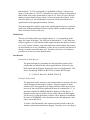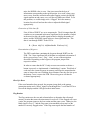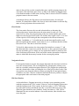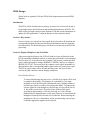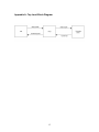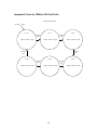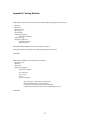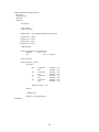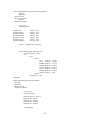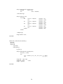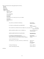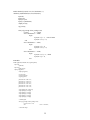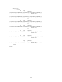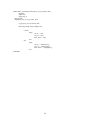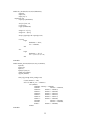
1
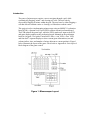
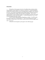
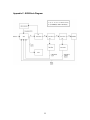
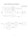
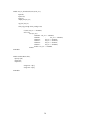
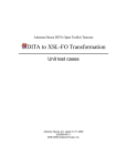
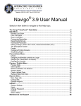
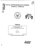
Minesweeper
Final Project Report
December 12, 2002
E155
Gigi Au and Daniel Vaughan
Abstract:
Minesweeper is a game where the user is challenged to identify hidden mines and clear
safe cells. Since the existing version of the game is only available for a computer, users
who are bored of staring at the monitor may want to play the game using a different
display. This project prototypes minesweeper using a keypad, an HC11 microcontroller,
a Spartan FPGA, and a perforation board containing a grid of ‘minefield’ LEDs, six
seven-segment game status displays, and win/lose LEDs. The user uses a keypad to
navigate through the grid, clear or flag mines, or reset the game. The FPGA decodes the
keypress and sends it to the microcontroller, which controls the game logic. The
microcontroller, in turn, sends data back to the FPGA, which decodes the input signals
and routes them to the LED grid and game status displays.
Introduction
The game of minesweeper requires a user to navigate through a grid, while
systematically flagging “mines” and clearing safe cells. The user wins by
successfully flagging all mines within the grid. The user loses by either flagging a
cell that does not contain a mine or clearing a cell that does contain a mine.
This project involves implementing minesweeper using an M68HC11 evaluation
board (EVB), a Spartan xcs10-3pc84 FPGA, and an external perforated board.
The EVB controls the game logic, while the FPGA sends user input to the EVB
and game display updates to the perforation board. Mounted on the perforation
board is a keypad, a 5x6 grid of ‘minefield’ LEDs, a ‘win’ LED, a ‘lose’ LED,
and four dual 7-segment displays to show current game information (row and
column indices, time, and number of mines adjacent to current position). Figure 1
below illustrates the layout of the game. Please refer to Appendix A for a top level
block diagram of the game control.
Figure 1: Minesweeper Layout
2
Schematics
The hardware for the project is placed on a breadboard and a perforation board.
The breadboard consists of the FPGA, transistors, and resistors. The perforation board
consists of the 5x6 grid of LEDs, six seven-segment displays, a keypad, a win LED and a
lose LED. The LED grid is illuminated using a polling method: LED status information
is sent to the appropriate column while that column is being polled. The six sevensegment displays are time-multiplexed using a selector signal driven by the system clock
and transistors to switch between the displays. A similar polling method is also used to
interpret the button press on the keypad.
The FPGA and EVB communicate through Ports A, B and C. The FPGA sends
the keypress signal to the EVB through Port A. The EVB determines the new game
status update and then sends 2 bytes of data, A and B, back to the FPGA through Ports B
and C, respectively.
A schematic of the integrated system appears on the following page.
3
5V
SCHEMATIC
Row Display
VDD6
A6
B6
C6
7-Segment D6
E6
Display
F6
G6
1 kOhm
Column Display
VDD5
A5
B5
C5
7-Segment D5
E5
Display
F5
G5
LED Grid
# of mines
display
VDD4
A4
B4
C4
7-Segment D4
Display
E4
F4
G4
100
ohms
47k
Ohm
5V
Sel[5:0] Gridcol[4:0]
Minutes Display
A3
B3
C3
7-Segment D3
E3
Display
F3
G3
Columns[3:0]
Poller[5:0]
VDD3
FPGA
10s of sec
display
Keypad
EVB
Rows[3:0]
VDD2
A2
B2
C2
D2
7-Segment
E2
Display
F2
G2
47kohms
5V
Sec
Display
Win
330
ohms
Seg[6:0]
A1
B1
C1
7-Segment D1
Display
E1
F1
G1
Lose
VDD1
330
ohms
Keypress[2:0]
A[7:0]
B[7:0]
4
Win
LED
Lose
LED
PORTA
PORTB
PORTC
Microcontroller Design
Logical control of minesweeper is conducted within the HC11 Microcontroller. The
breakdown of the HC11 game management code is organized as follows:
1. Definitions and Initializations
2. Pattern Generation
3. Start Routine
a. Position Check Routine
b. Write output data
c. Read input data
d. Determine Keypress
4. Clear Routine
5. Flag Routine
6. Navigation Routines
7. Win/Lose Routines
An .rst file of our assembly code appears in Appendix B, while a block diagram of the
EVB game logic appears in Appendix C. The following descriptions will walk the reader
through the primary routines and algorithms used in the HC11 code.
Port Definitions
Define memory locations for PORTA, PORTB, PORTC, DDRC, and TCNT.
Variable Definitions
Patterns are defined for: navigation directions, clear, flag, reset, loser, winner, and
various masks. Memory locations $C100 - $C167 are set aside for the mine
pattern plus a perimeter of empty cells, where each memory location contains a
‘cell cleared’ indicator and a ‘mine’ indicator in the least two significant bits,
respectively. Memory locations are also reserved for storing the win/lose signal
(WINLOSE), row and column indices (RINDEX, CINDEX), blink and status
signals (BLINK, STATUS), the number of mines surrounding a cell
(NUMMINE), and the signal that enables the number of mines to be displayed
(NUMEN). Additional locations are reserved for various counters used internally
to generate the output signals.
Pattern Generator
We have developed a routine for generating a seemingly random mine sequence.
A mine pattern is generated by iteratively examining the lowest 8 bits of the EVB
timer for 30 cycles. For a single cycle, the timer bits are added to a seed, and this
value becomes the new seed for each successive cycle. A mine will be placed in
the memory location corresponding to the cycle number only if the seed is less
5
than decimal# –78. This corresponds to a probability of about 1/5 because the
range of seed values is (-128:127). Alternatively, a mine will not be designated in
that location if the seed is greater than or equal to -78. After 30 cycles, the total
number of mines should average 6 (but it is not restricted to this value!). At the
end of the final cycle, the information for each cell will be stored in the least
significant bit of the appropriate memory location.
The pattern generator could be improved by multiplying the timer by a relatively
prime seed, adding an additional relatively prime number, and then setting that
value as the new seed for each cycle.
Initializations
The row and column indices are initially both set to ‘1’ (corresponding to the
upper left corner of the grid). The LEDs are all initialized to ‘1’ (on), blink and
win/lose signals to ‘0’ (off) and the enable signal to display the number of mines
to ‘0’ (off). Various counters, such as the total mine counter and the flag counter
are also initially set to zero. In addition, a value of zero is stored in a perimeter of
memory locations around the mine grid – this allows for the use of a common
procedure to recursively count adjacent mines.
Start Routine
Generation of 8-bit data (A)
The program begins by generating an 8-bit output that consists of the
column and row indices in the 6 most significant bits, followed by the
blink signal and on/off status signal in the least two significant bits. This
data is sent through PORTB to the FPGA to control the LED grid.
A = [ Col(2:0) Row(2:0) BLINK STATUS]
Check for Cleared Cell
The program uses the current row and column indices to reference the byte
stored in that particular memory location. Since the number of mines
around a cell is not supposed to be displayed if that cell has not yet been
uncovered, the second least significant bit must be examined for a ‘1’ to
determine whether NUMMINE should be displayed. If this bit is a ‘1,’
then the user has uncovered this cell previously and the NUMEN signal
will be set to 1 so that the number of mines can be displayed. In addition,
the value of NUMMINE is also determined so that the appropriate value
can be sent to the FPGA.
To achieve full functionality, this routine must also include a check for
whether a particular mine has been flagged. Currently, once a user flags a
6
mine, the BLINK value is set to 1 but is not stored in the byte of
information corresponding to that grid location. As a result, when a user
moves away from the current location after flagging a mine, the BLINK
signal remains on and causes every cell the user lands on to blink. To fix
this problem, we could simply store a “flagged” bit in the memory
location for each cell and use that value to adjust the blink signal
appropriately.
Generation of 8-bit data (B)
First, all bits of PORTC are set to output mode. The 8-bit output data (B)
contains a reset command in the most significant bit, the number of mines
in the next four bits, the enable signal needed to display the number of
mines, and the WINLOSE signal in the two least significant bits. This
data is sent through PORTC to the FPGA.
B = [ Reset Adj(3:0) AdjMineEnable WinLose(1:0) ]
Determination of Keypress
The FPGA sends data containing the keypress through PORTA to the
EVB. The 3 least significant bits of the data are examined to determine if
the key pressed was ‘reset’, ‘flag’, ‘clear’, or one of the navigation
directions. Depending on the keypress, the program jumps to the
respective routine.
In order to ensure that the HC11 only executes one routine each time a
button is pressed, we implemented a “handshaking” routine. This block of
code stores the current keypress in memory and keeps the output data the
same as long as the user is holding down a button. Once the user lets up on
the button, a zero is sent to the EVB. The next keypress will then be
evaluated appropriately.
Check for Reset
If the reset button has been pressed, the program jumps back to the pattern
generation routine and a “Reset” signal is sent through Port C to tell the FPGA to
reset all the displays and the LED grid to their initial states.
Flag Routine
The flag routine uses the row and column indices to determine the referenced
memory location that stores the mine status for each cell. If the flagged cell is not
a mine, the program jumps to the lose routine and the game resets. Otherwise, the
blink signal is set to ‘1’ and the flag count is incremented to keep track of the
number of correctly flagged mines. If the flag count equals the total number of
7
mines in the grid, the user has completed the game, and the program jumps to the
win routine, after which the game resets. As long as the number of flagged mines
is less than the number of total mines, the flag count is stored in FLGCNT and the
program returns to the start routine.
As mentioned above, the flag status is not stored into memory for each grid
location. We should have added a few lines of code in this routine to store the flag
status of each grid point to the associated cell.
Clear Routine
The clear routine first uses the row and column indices to determine the
referenced memory location that stores the mine status for each cell. If the
cleared cell is a mine, the program jumps to the lose routine and the game resets.
Otherwise, the user has cleared a safe cell, and the status signal is set to ‘0’ to turn
off the respective LED in the grid that corresponds to the referenced memory
location. In addition, a ‘1’ is loaded into the second least significant bit (recall
that least significant bit contains ‘mine status (0 or 1)’) to indicate that the cell has
been uncovered. This data is stored into memory.
To check for adjacent mines, the clear routine first initializes a counter ‘Y’ and
then determines the current user position. Because we have generated a perimeter
of zeros around the grid, we simply use one routine that checks for mines in each
of the 8 adjacent grid locations. At the end of this routine, the number of adjacent
mines is stored into the memory location for the current grid position.
Navigation Routine
If a navigation button is pressed, the program determines the direction in which to
move the current position. This is accomplished by changing the column or row
index in accordance with the navigation direction. The program also prohibits the
row and column indices from exceeding the size of the grid. In other words, if the
user position were along the leftmost column, pressing the left navigation button
would have no effect. After the routine has determined the new position, it adjusts
the appropriate index and returns to the main program.
Win/Lose Routines
As described above, flagging incorrectly or clearing a space containing a mine
sends the program to the ‘Lose’ routine. Likewise, correctly flagging all the mines
sends the program to the ‘Win’ routine. In the lose routine, a ‘Lose’ LED lights
up on the game board to remind the user they’ve just been blown to pieces, after
which the game should be reset. Similarly, in the win routine, a ‘Win’ LED is
illuminated for one second to indicate a successful mission, after which the user
resets the game.
8
FPGA Design
(Please refer to Appendix D for the FPGA block diagram and associated FSM
digrams)
Introduction
The FPGA will be divided into two primary sections. One section will decode a
keypad input into a specified format and send this information to the EVB. The
other section will input control signals from the EVB and use this information to
update the LED grid and the 7-segment displays on the perforation board.
Section 1: Key decoder
Upon receiving a row input from the keypad, the key decoder will determine the
corresponding column position and decode this information once the signal has
been debounced. The decoded keypress will then be sent directly to the EVB for
processing.
Section 2: Display Multiplexer and Grid Poller
After processing the keypress, the EVB will send two bytes of data back to the
FPGA containing information on how to control the grid and the various displays.
The first byte (A), as described in the Assembly Code section, contains bits that
specify which grid point to change (RINDEX, CINDEX), and how to change it
(BLINK, STATUS). The second byte (B) contains a reset signal, the number of
adjacent mines and a corresponding enable signal, and a two-bit win/lose signal.
The FPGA signal control can be divided into three parts: the clock dividerselector, the grid controller, and the display multiplexer.
Clock Divider/Selector
To ensure that blurring does not occur, a divided clock signal will be used
to multiplex the displays. The displays are controlled by a six-input
multiplexer while the LED grid is illuminated using a polling method. A
one-hot logic scheme is used to select among the inputs. To generate the
selector signal for each multiplexer, the first step is to tap out the lowest
11 bits of the system clock. This will yield a divided clock signal
operating at approximately 1 kHz. By choosing six 11-bit reference
numbers that are approximately evenly spaced apart, it is ensured that the
multiplexer inputs will be selected at even intervals. Before entering the
multiplexers, the six 11-bit numbers will be encoded using one-hot logic
so that the appropriate signals can be selected.
9
Grid Controller
The grid controller inputs the A byte and outputs six column vectors to be
multiplexed and sent to the LED grid. The grid controller uses the
reference position information stored in byte A to determine which LED
to alter, and the blink and status bits are used to determine how the
selected LED is to be altered (e.g. ON à OFF or ONà BLINK).
Display Multiplexer
The display multiplexer extracts the row and column indices from byte A,
the number of mines from byte B, and timer information (minutes, 10’s of
seconds, and seconds) from the time decoder. These six inputs are
multiplexed using selector signals that are generated by slowing down the
system clock. The selected signal is then decoded and sent to the
appropriate seven-segment display.
10
Results
For the most part, the game meets the original specifications: the perforation board and
game components behave correctly, the FPGA interfaces correctly with the EVB and
perforation board, and the HC11 code is reliable except for the flag routine. After loading
the .s19 file into the HC11 and running power to the FPGA, the game is ready to operate.
Upon reset, the LEDs all turn on, and the game timer starts over.
Perforation Board
The perforation board served as an excellent template for mounting the various
displays and routing many of the wires. Color-coded wires were used to tie
together common segments of the digital displays, which greatly reduced the
number of wires crossing between the board and the FPGA. A similar scheme was
used to illuminate the LED grid. In retrospect, a better-planned wiring diagram
would have eliminated much of the wire clutter. Most importantly, though, the
board and game components operated appropriately.
FPGA
The FPGA also operates properly. The keypress is successfully decoded and sent
to the EVB. The seven segment displays show the appropriate values of row and
column index, number of adjacent mines, and game time. The win and lose LEDs
both function appropriately. The grid of LEDs accurately displays the current
game status – LEDs can be turned on, off, or to a blinking state. One unusual
characteristic of the display that could not be accounted for is the tendency for the
‘seconds’ timer to bleed onto the ‘row index’ display. This may have to do with
the time multiplexing rate used to illuminate the 6 displays.
EVB
Within the EVB, the mine pattern is generated and stored in the proper memory
locations. Each of the EVB routines except for the flag routine behaves normally:
the navigation routines adjust user position appropriately, the clear routine sends
the correct status signal to the FPGA and outputs the appropriate number of
adjacent mines plus an enable signal. The win/lose routines also function as
planned. The position check routine accurately determines whether the current
position has been cleared and decides whether to display the number of adjacent
mines.
The primary unresolved problem with the HC11 code lies in the flag routine. By
not storing the flag status of each grid point, the BLINK signal that is sent to the
FPGA remains high indefinitely following the first successful flag. As mentioned
before, storing flag data in the memory location for each grid point could easily
fix this issue.
11
References:
[1] Franzon, Paul D. and David R. Smith. Verilog Styles for Synthesis of Digital Systems.
Upper Saddle River, New Jersey: Prentice Hall, 2000.
[2] M68HC11EVB Evaluation Board User’s Manual. First Edition. Motorola, Inc. 1986.
Parts List
Part
Perforated Board
Source
MarVac
Vendor Part #
4700T
12
Price
$15.97
Appendix A: Top Level Block Diagram
13
Appendix B: HC11 Assembly Code
0001
0002
0003
0004
0005
0006
0007
0008
0009
0010
0011
0012
0013
0014
0015
0016
0017
0018
0019
0020
0021
0022
0023
0024
0025
0026
0027
0028
0029
0030
0031
0032
0033
0034
0035
0036
0037
0038
0039
0040
0041
0042
0043
0044
0045
0046
0047
0048
0049
0050
0051
0052
0053
0054
0055
0056
0057
0058
0059
0060
0061
0062
0063
0064
0065
0066
0067
0068
0069
* mineswpr.asm -- Minesweeper Game Control
*
* Authors: Daniel Vaughan ([email protected]) and Gigi Au ([email protected])
* Date:
December 10, 2002
*
* This file inputs a keypad command through Port A from the FPGA and determines
* how to update the LED grid based upon the nature of the command.
* Output is stored in two bytes and sent out through ports B and C.
*
*
* Code Layout:
*
*
Subsection
Location
*______________________________________________________
*
Port Definitions.....................0031
*
Reserved Memory Locations............0042
*
Program Masks........................0073
*
Pattern Generator....................0100
*
Initializations......................0152
*
Start routine........................0200
*
Flag routine.........................0308
*
Clear routine........................0344
*
Win/Lose routine.....................0522
*
Navigation routines..................0535
*______________________________________________________
*
*
*
**************************
*
Port Definitions
*
**************************
1000
1004
1003
1007
100f
PORTA
PORTB
PORTC
DDRC
TCNT
EQU
EQU
EQU
EQU
EQU
$1000
$1004
$1003
$1007
$100F
************************************
*
Reserved Memory Locations
*
************************************
* Registers are reserved for the mine pattern
c032
WINLOSE
EQU
$C032
c033
c043
c034
c044
c045
RINDEX
RITEMP
CINDEX
CITEMP
KPTEMP
EQU
EQU
EQU
EQU
EQU
$C033
$C043
$C034
$C044
$C045
*
*
*
*
Store row
Temporary
Store col
Temporary
c035
c036
c037
c038
c03a
c039
c03b
c03c
c03d
c03e
BLINK
STATUS
REF1
REF2
NUMMIN1
NUMMINE
TOTMINE
NUMEN
FLGCNT
MINECT
EQU
EQU
EQU
EQU
EQU
EQU
EQU
EQU
EQU
EQU
$C035
$C036
$C037
$C038
$C03A
$C039
$C03B
$C03C
$C03D
$C03E
*
*
*
*
*
*
*
*
*
*
Blink LED command
LED on/off command
index reference
index reference
least significant byte of NUMMINE, number of adjacent mines
number of adjacent mines
total number of mines
enable number of adj. mines display (on/off)
number of flagged mines counter
number of adj. mines counter
c046
c048
c049
c050
SEED
MEMX
MEMX1
LOOPNUM
EQU
EQU
EQU
EQU
$C046
$C048
$C049
$C050
* pattern generator seed number
* memory to store current row position
number
rindex
number
cindex
in memory location $33
storage
in memory location $34
storage
* memory to store loop number in pattern gen.
14
0070
0071
0072
0073
0074
0075
0076
0077
0078
0079
0080
0081
0082
0083
0084
0085
0086
0087
0088
0089
0090
0091
0092
0093
0094
0095
0096
0097
0098
0099
0100
0101
0102
0103
0104
0105
0106
0107
0108
0109
0110
0111
0112
0113
0114
0115
0116
0117
0118
0119
0120
0121
0122
0123
0124
0125
0126
0127
0128
0129
0130
0131
0132
0133
0134
0135
0136
0137
0138
0139
0140
0141
0142
0143
0144
0145
c052
TEMP
EQU
$C052
*********************************
*
Program Masks
*
*********************************
0002
0005
0004
0001
UP
DOWN
LEFT
RIGHT
EQU
EQU
EQU
EQU
%00000010
%00000101
%00000100
%00000001
0003
0007
0006
0000
CLEAR
FLAG
RESET
NOPRESS
EQU
EQU
EQU
EQU
%00000011
%00000111
%00000110
%00000000
* Masks for action selections
0002
0003
00ff
0007
0005
0006
0095
CLRMASK
CLRMSK2
PCMASK
NAVMASK
FIVE
SIX
TESTNUM
EQU
EQU
EQU
EQU
EQU
EQU
EQU
%00000010
%00000011
%11111111
%00000111
%00000101
%00000110
%10010101
* Cleared location check mask
0002
0001
LOSER
WINNER
EQU
EQU
%00000010
%00000001
* lose mask
* win mask
*
*
*
*
*
* Masks for navigation directions
Port C --> output mask
navigation button mask
number five
number six
Pattern generator seed (dec. #149)
**************************
*
Pattern Generator
*
**************************
d100
d100
d103
d107
d109
d10c
d10e
d111
d114
d116
d119
d11b
d11c
d11f
d121
d125
d128
d12b
d12d
d12f
d132
d135
d137
d13a
d13d
d13e
d140
d142
d145
d147
d149
d14c
d14f
d150
d153
d155
d157
d159
d15c
d15f
d160
d163
ce
18
86
b7
86
b7
b6
8b
b7
c6
3a
8c
2e
18
ff
f6
18
86
b7
b6
8b
b7
b6
4c
81
2e
b7
c6
18
b6
f6
1b
b7
81
2e
86
18
f6
5c
f7
7e
00
ce
95
c0
00
c0
10
95
c0
10
00
00 01
00
4d
ce
c0
c0
3a
00
c0
10
95
c0
c0
50
pattern
46
3b
0f
rowloop
52
c0 01
48
49
50
0f
52
50
06
cf
c0 50
01
3a
10 0f
c0 46
c0 46
b2
0f
01
a7 ff
c0 3b
c0 3b
d1 32
colloop
ORG
$D100
LDX
LDY
LDAA
STAA
LDAA
STAA
LDAA
ADDA
STAA
LDAB
ABX
CPX
BGT
LDY
STX
LDAB
ABY
LDAA
STAA
LDAA
ADDA
STAA
LDAA
INCA
CMPA
BGT
STAA
LDAB
ABY
LDAA
LDAB
ABA
STAA
CMPA
BGT
LDAA
STAA
LDAB
INCB
STAB
JMP
#$00
#$01
#TESTNUM
SEED
#$00
TOTMINE
TCNT
#TESTNUM
TEMP
#$10
* Initialize row counter
* Initialize row + column counter
* Store test seed (#149) in memory
#$50
start
#$C001
MEMX
MEMX1
* Stop incrementing at bottom row of grid
#$00
LOOPNUM
TCNT
#TESTNUM
TEMP
LOOPNUM
*
*
*
*
Load lower 8 bits of counter
Add to test seed
Store in memory
Increment row address (2nd least sign. hex digit)
* Initialize row + column counter
* Store row number
* Use Y to store row + column
*set column loop counter to 0
* stop incrementing at far right column of grid
#$06
rowloop
LOOPNUM
#$01
* Increase column position by 1
TCNT
SEED
* Load bottom 8 bits of timer in accumulator A
* Load "random" seed into accumulator B
SEED
#$B2
setzero
#$01
$FF,Y
TOTMINE
*
*
*
*
*
TOTMINE
colloop
* Store the number of total mines in TOTMINE
* This will be generally around 6, but the unknown
15
Add timer and seed to form new seed
Compare (-128 -- 127) to (-78)
If greater than -78 (4/5 probability), set mine = 0
Otherwise (1/5 probability), set mine = 1
0146
0147
0148
0149
0150
0151
0152
0153
0154
0155
0156
0157
0158
0159
0160
0161
0162
0163
0164
0165
0166
0167
0168
0169
0170
0171
0172
0173
0174
0175
0176
0177
0178
0179
0180
0181
0182
0183
0184
0185
0186
0187
0188
0189
0190
0191
0192
0193
0194
0195
0196
0197
0198
0199
0200
0201
0202
0203
0204
0205
0206
0207
0208
0209
0210
0211
0212
0213
0214
0215
0216
0217
0218
0219
0220
0221
d166 86 00
d168 18 a7 ff
d16b 7e d1 32
setzero
LDAA
STAA
JMP
#$00
$FF,Y
colloop
* number makes the game a little more challenging
*****************************************
*
Initializations
*****************************************
d16e
d170
d173
d176
86
b7
b7
b7
01
c0 33
c0 34
c0 36
d179
d17b
d17e
d181
d184
d187
d18a
d18d
d190
d193
86
b7
b7
b7
b7
b7
b7
b7
b7
b7
00
c0
c0
c0
c0
c0
c0
c0
c0
c0
d196
d199
d19c
d19f
d1a2
d1a5
d1a8
d1ab
d1ae
d1b1
d1b4
d1b7
d1ba
d1bd
d1c0
d1c3
d1c6
d1c9
d1cc
d1cf
d1d2
d1d5
d1d8
d1db
d1de
d1e1
b7
b7
b7
b7
b7
b7
b7
b7
b7
b7
b7
b7
b7
b7
b7
b7
b7
b7
b7
b7
b7
b7
b7
b7
b7
b7
c1
c1
c1
c1
c1
c1
c1
c1
c1
c1
c1
c1
c1
c1
c1
c1
c1
c1
c1
c1
c1
c1
c1
c1
c1
c1
start
*
LDAA
STAA
STAA
STAA
#$01
RINDEX
CINDEX
STATUS
*
* Set initial row index to one
* Set initial column index to one
* Set initial Status signal to one (all LEDs on)
35
32
3c
3d
3e
45
50
39
3a
LDAA
STAA
STAA
STAA
STAA
STAA
STAA
STAA
STAA
STAA
#$00
BLINK
WINLOSE
NUMEN
FLGCNT
MINECT
KPTEMP
LOOPNUM
NUMMINE
NUMMIN1
*
*
*
*
*
*
*
*
*
*
00
01
02
03
04
05
06
07
10
20
30
40
50
60
17
27
37
47
57
67
61
62
63
64
65
66
STAA
STAA
STAA
STAA
STAA
STAA
STAA
STAA
STAA
STAA
STAA
STAA
STAA
STAA
STAA
STAA
STAA
STAA
STAA
STAA
STAA
STAA
STAA
STAA
STAA
STAA
$C100
$C101
$C102
$C103
$C104
$C105
$C106
$C107
$C110
$C120
$C130
$C140
$C150
$C160
$C117
$C127
$C137
$C147
$C157
$C167
$C161
$C162
$C163
$C164
$C165
$C166
* Create perimeter of zeros around mine grid to
* simplify adjacent mine counting procedure
*
* Actual mine sequence stored in
*
Row 1: $C111 - $C116
*
Row 2: $C121 - $C126
*
Row 3: $C131 - $C136
*
Row 4: $C141 - $C146
*
Row 5: $C151 - $C156
Set
Set
Set
Set
Set
Set
Set
Set
************************************
*
*
Start routine
*
*
************************************
Blink command to 'off'
WIN/LOSE command to 'off'
number of adjacent mines display to 'off'
flag counter to 0
adjacent mine counter to 0
initial keypress to 0
LOOPNUM to 0
number of mines to 0
*
*
*******************************
* Current Position Cleared? *
*******************************
d1e4 bd d3 ce
nav
JSR
posclr
* check if current position has been cleared
********************************
* send data out through PORT B *
********************************
d1e7
d1ea
d1eb
d1ec
d1ed
d1f0
d1f1
b6 c0 34
48
48
48
bb c0 33
48
bb c0 35
LDAA
LSLA
LSLA
LSLA
ADDA
LSLA
ADDA
CINDEX
*
*
*
*
RINDEX
BLINK
16
Generate an eight bit output with
column index in [7:5], row index in
[4:2], Blink in bit 1, and Status in
bit 0
0222
0223
0224
0225
0226
0227
0228
0229
0230
0231
0232
0233
0234
0235
0236
0237
0238
0239
0240
0241
0242
0243
0244
0245
0246
0247
0248
0249
0250
0251
0252
0253
0254
0255
0256
0257
0258
0259
0260
0261
0262
0263
0264
0265
0266
0267
0268
0269
0270
0271
0272
0273
0274
0275
0276
0277
0278
0279
0280
0281
0282
0283
0284
0285
0286
0287
0288
0289
0290
0291
0292
0293
0294
0295
0296
0297
d1f4 48
d1f5 bb c0 36
d1f8 b7 10 04
LSLA
ADDA
STAA
STATUS
PORTB
* Send information out over port B
********************************
* send data out through PORT C *
********************************
d1fb
d1fd
d200
d203
d204
d207
d208
d209
d20c
d20f
d211
#PCMASK
DDRC
NUMMIN1
c0 32
10 03
00
c0 3c
LDAA
STAA
LDAA
LSLA
ADDA
LSLA
LSLA
ADDA
STAA
LDAA
STAA
WINLOSE
PORTC
#$00
NUMEN
* WINLOSE in bits [1:0]
* Send information out over port C
* Set enable signal to 0
d214 b6 c0 32
d217 81 00
d219 27 1b
LDAA
CMPA
BEQ
WINLOSE
#$00
keyprs
* Branch to keypress if WINLOSE = 0
LDY
LDX
CPY
BEQ
INY
CPX
BEQ
INX
JMP
JMP
#$0000
#$0000
#$002A
pat2
* Display the win or lose LED for 1 second
* after user wins or loses
d21b
d21f
d222
d226
d228
d22a
d22d
d22f
d230
d233
86
b7
b6
48
bb
48
48
bb
b7
86
b7
18
ce
18
27
18
8c
27
08
7e
7e
ff
10 07
c0 3a
skipc
c0 3c
ce
00
8c
0b
08
0e
f0
00 00
00
00 2a
onesec
one_st
4e
one_lp
d2 2a
d1 00
pat2
NUMEN
* Set port C to all output mode
* Generate a seven bit output with the number of mines
* adjacent to current position in [6:3]
* NUMEN in bit 2
#$0E4E
one_st
one_lp
pattern
************************
* Determine Keypress *
************************
* Evaluates keypress and jumps to appropriate subroutine
d236
d239
d23b
d23d
d23f
d242
d245
d248
d249
d24b
d24e
d251
d253
d255
d257
d259
d25b
d25d
d25f
d261
d263
d265
d267
d269
d26b
d26d
b6
84
81
26
b7
7e
f6
11
26
7e
b7
81
27
81
27
81
27
81
27
81
27
81
27
81
27
7e
10
07
00
06
c0
d1
c0
00
keyprs
45
e4
45
noprs
03
d1 e4
c0 45
06
1b
07
1a
03
19
02
18
05
17
04
16
01
15
d1 e4
d270 7e d1 00
d273 7e d2 88
d276 7e d2 c3
holdon
pat
flg
clr
LDAA
ANDA
CMPA
BNE
STAA
JMP
LDAB
CBA
BNE
JMP
STAA
CMPA
BEQ
CMPA
BEQ
CMPA
BEQ
CMPA
BEQ
CMPA
BEQ
CMPA
BEQ
CMPA
BEQ
JMP
PORTA
#NAVMASK
#NOPRESS
noprs
KPTEMP
nav
KPTEMP
holdon
nav
KPTEMP
#RESET
pat
#FLAG
flg
#CLEAR
clr
#UP
up1
#DOWN
down1
#LEFT
left1
#RIGHT
right1
nav
JMP
JMP
JMP
pattern
flagged
cleared
*
*
*
*
Load value sent from FPGA
Only look at bottom three bits
If no button being pressed, keep sending same data
out ports B and C
* Load previous keypress
* If button being held down, keep sending same data
* out ports B and C
* Store current keypress in temporary location
* If reset pressed, then return to pattern generator
* If flag pressed, go to FLAG routine
* If clear pressed, go to CLEAR routine
* If up pressed, go to UP subroutine
* If down pressed, go to DOWN subroutine
* If left pressed, go to LEFT subroutine
* If right pressed, go to RIGHT subroutine
* Otherwise, return to start routine
17
0298
0299
0300
0301
0302
0303
0304
0305
0306
0307
0308
0309
0310
0311
0312
0313
0314
0315
0316
0317
0318
0319
0320
0321
0322
0323
0324
0325
0326
0327
0328
0329
0330
0331
0332
0333
0334
0335
0336
0337
0338
0339
0340
0341
0342
0343
0344
0345
0346
0347
0348
0349
0350
0351
0352
0353
0354
0355
0356
0357
0358
0359
0360
0361
0362
0363
0364
0365
0366
0367
0368
0369
0370
0371
0372
0373
d279
d27c
d27f
d282
7e
7e
7e
7e
d4
d4
d4
d4
12
20
2e
3c
up1
down1
left1
right1
d285 7e d1 e4
JMP
JMP
JMP
JMP
navup
navdown
navleft
navrt
JMP
nav
* Once done with routine, return to start
****************************
*
*
Flag Routine
*
*
****************************
*
*
* Checks to see if mine in current location. If no, user loses. If yes, stores
* a 1 in the blink signal, increments the flag counter, and returns to start
d288
d28b
d28c
d28d
d28e
d28f
d292
d294
d297
d29a
d29d
d29e
d2a0
d2a2
d2a4
d2a7
d2a9
d2ac
d2ae
d2b1
d2b4
d2b5
d2b8
d2ba
d2bd
d2c0
b6
48
48
48
48
bb
8b
b7
f6
ce
3a
a6
81
27
7e
86
b7
86
b7
b6
4c
b1
27
b7
7e
7e
c0 33
c0
01
c0
c0
c0
ff
01
03
d4
01
c0
00
c0
c0
c0
06
c0
d1
d4
flagged
34
37
37
00
05
flag1
35
36
3d
3b
3d
e4
0a
winner
LDAA
LSLA
LSLA
LSLA
LSLA
ADDA
ADDA
STAA
LDAB
LDX
ABX
LDAA
CMPA
BEQ
JMP
LDAA
STAA
LDAA
STAA
LDAA
INCA
CMPA
BEQ
STAA
JMP
JMP
RINDEX
* Shift RINDEX 2^4 = 1 hex number to left
CINDEX
#$01
REF1
REF1
#$C000
* Set X to zero
$FF,X
#$01
flag1
lose
#$01
BLINK
#$00
STATUS
FLGCNT
* Load B'th element of X (B'th element of mine pattern)
*
* If it was not a mine, they lose
* Otherwise, load BLINK with blink signal
*
*
*
*
*
TOTMINE
winner
FLGCNT
nav
win
*************************
*
*
Clear Routine
*
*
*************************
Load current flag count
Increment flag count by one
Compare it to total number of mines
If user has flagged every mine, they win
If not, then store new flag count and return to start
*
*
* Checks to see if mine in current location. If yes, user loses. If no, checks adjacent
* spaces for mines, records number of adjacent mines, and returns to start
******************************
*
Mine Check
*
******************************
d2c3
d2c6
d2c7
d2c8
d2c9
d2ca
d2cd
d2cf
d2d2
d2d5
d2d8
d2d9
d2db
d2dd
d2df
d2e2
d2e4
d2e7
b6
48
48
48
48
bb
8b
b7
f6
ce
3a
a6
81
26
7e
c6
f7
8b
c0 33
c0
01
c0
c0
c0
cleared
34
37
37
00
ff
01
03
d4 05
00
c0 36
02
clear1
LDAA
LSLA
LSLA
LSLA
LSLA
ADDA
ADDA
STAA
LDAB
LDX
ABX
LDAA
CMPA
BNE
JMP
LDAB
STAB
ADDA
RINDEX
* Shift RINDEX 2^4 = 1 hex number to left
CINDEX
#$01
REF1
REF1
#$C000
$FF,X
#$01
clear1
lose
#$00
STATUS
#CLRMASK
* Set X to zero
* Load B'th element of X (B'th element of mine pattern)
* If it was a mine, go to lose (you lose)
*
* Store 0 into STATUS to turn off LED
*
18
0374
0375
0376
0377
0378
0379
0380
0381
0382
0383
0384
0385
0386
0387
0388
0389
0390
0391
0392
0393
0394
0395
0396
0397
0398
0399
0400
0401
0402
0403
0404
0405
0406
0407
0408
0409
0410
0411
0412
0413
0414
0415
0416
0417
0418
0419
0420
0421
0422
0423
0424
0425
0426
0427
0428
0429
0430
0431
0432
0433
0434
0435
0436
0437
0438
0439
0440
0441
0442
0443
0444
0445
0446
0447
0448
0449
d2e9 a7 ff
STAA
$FF,X
* Store 1 into "cleared" to indicate spot has been cleared
************************
*
Mine Count
*
************************
* Check mine pattern to see if there's a mine. Earlier routines choose which
* mine count routines to jump to, depending on current grid position
d2eb 18 ce 00 00
d2ef
d2f2
d2f5
d2f8
d2fa
d2fd
d300
d303
d306
d309
d30b
d30e
d311
d314
d316
d319
d31c
d31e
d321
d324
d327
d329
d32c
d32f
d332
d335
d338
d33a
d33d
d340
d342
d345
d348
d34b
d34d
d350
d353
d355
d358
d35b
d35e
d360
d363
d366
d369
d36c
d36f
d371
d374
d377
d379
d37c
b6
b7
b6
8b
b7
bd
b6
b7
b6
8b
b7
bd
b6
8b
b7
b6
8b
b7
bd
b6
8b
b7
b6
b7
bd
b6
8b
b7
b6
8b
b7
bd
b6
8b
b7
b6
8b
b7
bd
b6
8b
b7
b6
b7
bd
b6
8b
b7
b6
8b
b7
bd
c0
c0
c0
ff
c0
d3
c0
c0
c0
01
c0
d3
c0
ff
c0
c0
ff
c0
d3
c0
ff
c0
c0
c0
d3
c0
ff
c0
c0
01
c0
d3
c0
01
c0
c0
ff
c0
d3
c0
01
c0
c0
c0
d3
c0
01
c0
c0
01
c0
d3
33
43
34
d37f
d383
d386
d387
d388
d38b
d38e
d38f
d390
18
b6
48
48
b7
b6
48
48
48
ff c0 39
c0 3a
44
ad
33
43
34
44
ad
33
LDY
#$00
nextl
LDAA
STAA
LDAA
ADDA
STAA
JSR
LDAA
STAA
LDAA
ADDA
STAA
JSR
LDAA
ADDA
STAA
LDAA
ADDA
STAA
JSR
LDAA
ADDA
STAA
LDAA
STAA
JSR
LDAA
ADDA
STAA
LDAA
ADDA
STAA
JSR
LDAA
ADDA
STAA
LDAA
ADDA
STAA
JSR
LDAA
ADDA
STAA
LDAA
STAA
JSR
LDAA
ADDA
STAA
LDAA
ADDA
STAA
JSR
RINDEX
RITEMP
CINDEX
#$FF
CITEMP
adj_chk
RINDEX
RITEMP
CINDEX
#$01
CITEMP
adj_chk
RINDEX
#$FF
RITEMP
CINDEX
#$FF
CITEMP
adj_chk
RINDEX
#$FF
RITEMP
CINDEX
CITEMP
adj_chk
RINDEX
#$FF
RITEMP
CINDEX
#$01
CITEMP
adj_chk
RINDEX
#$01
RITEMP
CINDEX
#$FF
CITEMP
adj_chk
RINDEX
#$01
RITEMP
CINDEX
CITEMP
adj_chk
RINDEX
#$01
RITEMP
CINDEX
#$01
CITEMP
adj_chk
* look in cell left of current position
STY
LDAA
LSLA
LSLA
STAA
LDAA
LSLA
LSLA
LSLA
NUMMINE
NUMMIN1
* Store total mine count in NUMMIN1
nextr
nextul
43
34
44
ad
33
nextu
43
34
44
ad
33
nextur
43
34
44
ad
33
nextbl
43
34
44
ad
33
nextb
43
34
44
ad
33
nextbr
43
34
44
ad
c0 3a
c0 33
* Initialize mine counter
* look in cell right of current position
* look in cell above, left of current position
* look in cell above current position
* look in cell to right of current position
* look in cell below, left of current position
* look in cell below current position
* look in cell below, right of current position
NUMMIN1
RINDEX
19
0450
0451
0452
0453
0454
0455
0456
0457
0458
0459
0460
0461
0462
0463
0464
0465
0466
0467
0468
0469
0470
0471
0472
0473
0474
0475
0476
0477
0478
0479
0480
0481
0482
0483
0484
0485
0486
0487
0488
0489
0490
0491
0492
0493
0494
0495
0496
0497
0498
0499
0500
0501
0502
0503
0504
0505
0506
0507
0508
0509
0510
0511
0512
0513
0514
0515
0516
0517
0518
0519
0520
0521
0522
0523
0524
0525
d391
d392
d395
d397
d39a
d39d
d3a0
d3a1
d3a3
d3a5
d3a8
d3aa
48
bb
8b
b7
f6
ce
3a
a6
84
bb
a7
7e
c0
01
c0
c0
c0
LSLA
ADDA
ADDA
STAA
LDAB
LDX
ABX
LDAA
ANDA
ADDA
STAA
JMP
34
37
37
00
ff
03
c0 3a
ff
d1 e4
* Shift RINDEX 2^4 = 1 hex number to left
CINDEX
#$01
REF1
REF1
#$C000
* Set X to zero
$FF,X
#CLRMSK2
NUMMIN1
$FF,X
nav
* Load B'th element of X (B'th element of mine pattern)
* store number of mines in memory for this
* cell location
************************************
* Adjacent Mine Check Subroutine *
************************************
d3ad
d3b0
d3b1
d3b2
d3b3
d3b4
d3b7
d3b9
d3bc
d3bf
d3c2
d3c3
d3c5
d3c7
d3c9
d3cb
d3cd
b6
48
48
48
48
bb
8b
b7
f6
ce
3a
a6
84
81
26
18
39
c0 43
c0
01
c0
c0
c0
adj_chk
44
38
38
00
ff
01
01
02
08
chk_out
LDAA
LSLA
LSLA
LSLA
LSLA
ADDA
ADDA
STAA
LDAB
LDX
ABX
LDAA
ANDA
CMPA
BNE
INY
RTS
RITEMP
* Shift RINDEX 2^4 = 1 hex number to left
CITEMP
#$01
REF2
REF2
#$C000
* Set X to zero
*
* Check mine pattern to see if there's a mine
* Examine adjacent position for mine
$FF,X
#$01
#$01
chk_out
* Increment mine counter if mine found nearby
*******************************
* Current Position Cleared? *
*******************************
d3ce
d3d1
d3d2
d3d3
d3d4
d3d5
d3d8
d3da
d3dd
d3e0
d3e3
d3e4
d3e6
d3e8
d3ea
d3ec
d3ee
d3f1
d3f3
d3f4
d3f5
d3f8
d3fa
d3fd
d3ff
d401
d404
b6
48
48
48
48
bb
8b
b7
f6
ce
3a
a6
84
81
26
86
b7
a6
44
44
b7
86
b7
20
86
b7
39
c0 33
c0
01
c0
c0
c0
posclr
34
37
37
00
ff
02
02
13
01
c0 3c
ff
c0 3a
00
c0 36
05
01
c0 36
skippos
skp2
LDAA
LSLA
LSLA
LSLA
LSLA
ADDA
ADDA
STAA
LDAB
LDX
ABX
LDAA
ANDA
CMPA
BNE
LDAA
STAA
LDAA
LSRA
LSRA
STAA
LDAA
STAA
BRA
LDAA
STAA
RTS
RINDEX
* Shift RINDEX 2^4 = 1 hex number to left
CINDEX
#$01
REF1
REF1
#$C000
* Set X to zero
$FF,X
#CLRMASK
#CLRMASK
skippos
#$01
NUMEN
$FF,X
* Load B'th element of X (B'th element of mine pattern)
* Check to see if current position has been cleared
* If not, don't display number of adjacent mines
* If clear, activate enable signal to display # adj. mines
NUMMIN1
#$00
STATUS
skp2
#$01
STATUS
**************************
*
*
* Win/Lose Subroutine
*
*
**************************
* Load a zero into status to turn off LED
* If position has not been cleared, keep LED on
*
20
0526
0527
0528
0529
0530
0531
0532
0533
0534
0535
0536
0537
0538
0539
0540
0541
0542
0543
0544
0545
0546
0547
0548
0549
0550
0551
0552
0553
0554
0555
0556
0557
0558
0559
0560
0561
0562
0563
0564
0565
0566
0567
0568
0569
0570
0571
0572
0573
0574
0575
0576
0577
0578
0579
0580
0581
0582
0583
0584
0585
0586
d405
d407
d40a
d40c
d40f
86
b7
86
b7
7e
02
c0 32
01
c0 32
d1 e4
lose
win
LDAA
STAA
LDAA
STAA
JMP
#LOSER
WINLOSE
#WINNER
WINLOSE
nav
* Set win/lose to lose
* Set win/lose to win
*******************************
*
*
*
Navigation Subroutines
*
*
*
*******************************
* Checks current grid position and adjusts row/column indices
* according to navigation direction specified by user.
**********
*
up
*
**********
d412
d415
d417
d419
d41a
d41d
b6
81
27
4a
b7
7e
c0 33
01
04
c0 33
d1 e4
navup
LDAA
CMPA
BEQ
DECA
STAA
up
RINDEX
#$01
up
RINDEX
JMP
*If already at top row, do not decrease row index
nav
* Return to start routine when done
**********
* down *
**********
d420
d423
d425
d427
d428
d42b
b6
81
27
4c
b7
7e
c0 33
05
04
c0 33
d1 e4
navdown
down
LDAA
CMPA
BEQ
INCA
STAA
JMP
RINDEX
#$05
down
* If already at bottom row, do not increase row index
RINDEX
nav
* Return to start routine when done
CINDEX
#$01
left
* If already at leftmost column, do not decrease
* column index
CINDEX
nav
* Return to start routine when done
CINDEX
#$06
right
* If already at rightmost column, do not increase
* column index
CINDEX
nav
* Return to start routine when done t increase
**********
* left *
**********
d42e
d431
d433
d435
d436
d439
b6
81
27
4a
b7
7e
c0 34
01
04
c0 34
d1 e4
navleft
left
LDAA
CMPA
BEQ
DECA
STAA
JMP
***********
* right *
***********
d43c
d43f
d441
d443
d444
d447
b6
81
27
4c
b7
7e
c0 34
06
04
c0 34
d1 e4
navrt
right
LDAA
CMPA
BEQ
INCA
STAA
JMP
21
Appendix C: EVB Block Diagram
22
Appendix D: FPGA Block Diagram and FSM Diagrams
23
Appendix D (Cont’d): Keypad Debouncer FSM
Nopress = 1
Reset
Nopress = &rows
Nopress = 0
S0
00
S1
01
Nopress = 1
Nopress = 0
Nopress = 0
Nopress = 1
Nopress = 0
S3
10
S2
11
Nopress = 1
Output Logic
En = state[1]&state[0]
24
Appendix D (Cont’d): Keypad Scanner FSM
Nopress_bar
Reset
Nopress_bar
Nopress = 1111
Nopress
S0
0111
S1
1011
Nopress
Nopress
Nopress_bar
Nopress_bar
S3
1110
S2
1101
Nopress
25
Appendix D (Cont’d): FSM for LED Grid Poller
Poller FSM for LED Grid
Reset
011111
110111
101111
Posedge
sclk
Output = Column 1 of grid
Posedge
sclk
Output = Column 2 of grid
Output = Column 3 of grid
Posedge
sclk
Posedge
sclk
111110
111101
Posedge
sclk
Output = Column 6 of grid
111011
Posedge
sclk
Output = Column 5 of grid
26
Output = Column 4 of grid
Appendix E: Verilog Modules
module Final_Project(rows,clk,reset,keypress,columns,A,B,seg,gridcol,poller,sel,win,lose);
input clk;
input reset;
input [3:0] rows;
input [7:0] A;
input [6:0] B;
output [2:0] keypress;
output [3:0] columns;
output [6:0] seg;
output [5:0] poller,sel;
output [4:0] gridcol;
output win, lose;
FPGA2EVB FPGA2EVB2(rows,clk,reset,keypress,columns);
minesweeper minesweeper2(clk,reset,A,B,seg,gridcol,poller,sel,win,lose);
endmodule
module FPGA2EVB(rows,clk,reset,keypress,columns);
input [3:0] rows;
input clk;
input reset;
output [2:0] keypress;
output [3:0] columns;
wire sclk, bclk;
wire [11:0] y;
wire en;
wire [3:0] columns;
slow_clock slow_clock3(clk,reset,sclk,bclk,y);
debouncer debouncer3(reset,rows,sclk,en);
keyscanner keyscanner3(sclk,reset,rows,columns);
keydecoder keydecoder3(clk,reset,rows,columns,keypress,en);
endmodule
27
module debouncer(reset,rows,sclk,en);
input reset;
input [3:0] rows;
input sclk;
output en;
wire nopress;
reg [1:0] state;
reg [1:0] nextstate;
assign nopress = (rows[3]&rows[2]&rows[1]&rows[0]);
parameter S0 = 2'b00;
parameter S1 = 2'b01;
parameter S2 = 2'b11;
parameter S3 = 2'b10;
// State Register
always @(posedge sclk or posedge reset)
if (reset)
state <= S0;
else
state <= nextstate;
//Next state logic
always @(state or nopress)
case (state)
S0:
S1:
S2:
S3:
if (nopress)
else
if (nopress)
else
if (nopress)
else
if (nopress)
else
nextstate <= S0;
nextstate <= S1;
nextstate <= S0;
nextstate <= S2;
nextstate <= S3;
nextstate <= S2;
nextstate <= S0;
nextstate <= S1;
default: nextstate <= S0;
endcase
// Output Logic
assign en = (state[1]&state[0]);
endmodule
28
module keydecoder(clk,reset,rows,columns,keypress,en);
input clk;
input reset;
input [3:0] rows;
input [3:0] columns;
input en;
output [2:0] keypress;
wire [7:0] A;
reg [2:0] keypress;
parameter UP
parameter LEFT
parameter DOWN
parameter RIGHT
parameter CLEAR
parameter FLAG
parameter RESET
= 8'b1011_0111;
= 8'b0111_1011;
= 8'b1011_1011;
= 8'b1101_1011;
= 8'b0111_1101;
= 8'b1011_1101;
= 8'b1101_1101;
assign A = {columns[3:0], rows[3:0]};
always @(posedge clk or posedge reset)
if (reset) keypress <= 3'b0;
else
if (en)
case(A)
UP:
keypress <= 3'b010;
LEFT: keypress <= 3'b100;
DOWN: keypress <= 3'b101;
RIGHT: keypress <= 3'b001;
CLEAR: keypress <= 3'b011;
FLAG: keypress <= 3'b111;
RESET: keypress <= 3'b110;
default: keypress <= 3'b0;
endcase
else keypress <= 3'b0;
endmodule
module keyscanner(clk,reset,rows,columns);
input clk;
input reset;
input [3:0] rows;
output [3:0] columns;
reg [3:0] state;
reg [3:0] nextstate;
parameter nopress = 4'b1111;
parameter S0 = 4'b0111;
parameter S1 = 4'b1011;
parameter S2 = 4'b1101;
parameter S3 = 4'b1110;
// State Register
29
always @(posedge clk or posedge reset)
if (reset)
state <= S0;
else
state <= nextstate;
// Next State Logic
always @(state or rows)
case (state)
S0:
S1:
S2:
S3:
if (rows == nopress)
else
if (rows == nopress)
else
if (rows == nopress)
else
if (rows == nopress)
else
default:
nextstate <= S1;
nextstate <= state;
nextstate <= S2;
nextstate <= state;
nextstate <= S3;
nextstate <= state;
nextstate <= S0;
nextstate <= state;
nextstate <= S0;
endcase
// Output Logic
assign columns = state;
endmodule
module slow_clock(clk,reset,sclk,bclk,y);
input clk;
input reset;
output sclk;
output bclk;
output [10:0] y;
reg [19:0] q;
always @(posedge clk or posedge reset)
if (reset) q <= 20'b0;
else
if (q == 20'b1111_1111_1111_1111_1111) q <= 20'b0;
else
q <= q + 1;
assign sclk = ~q[6]; //q[6]
assign bclk = q[16];
//q[16]
assign y = q[10:0];
endmodule
30
module minesweeper(clk,reset,A,B,seg,gridcol,poller,sel,win,lose);
input clk;
input reset;
input [7:0] A;
input [6:0] B;
output [6:0] seg;
output [5:0] poller,sel;
output [4:0] gridcol;
output win, lose;
wire [1:0] blinkstatus;
wire sclk, bclk;
wire [59:0] L;
wire [10:0] y;
wire [4:0] row_in, col_in, mine_num, sec, ten_sec, minutes;
wire [4:0] loc;
wire [4:0] q;
wire [5:0] poller,sel;
wire en;
slow_clock slow_clock2(clk,reset,sclk,bclk,y);
//input clk,reset
//output sclk,bclk,y
loc_decoder loc_decoder2(clk,reset,A,loc,blinkstatus);
//input A
//output loc,blinkstatus
index_decoder index_decoder2(clk,reset,A[7:2],B[6:2],row_in,col_in,mine_num);
//input A,B
//output row,col,mine#
blinkoff_fsm blinkoff_fsm2(clk, reset, loc, blinkstatus, L);
//input loc,blinkstatus,reset
//,sclk,bclk,output L
gridpoller gridpoller2(sclk,bclk,reset,L,gridcol,poller);
//input sclk,reset,L
//output gridcol,poller
sec_decoder sec_decoder2(clk,reset,sec,en);
ten_sec_decoder ten_sec_decoder2(clk,reset,en,ten_sec);
minute_decoder minute_decoder2(clk,reset,en,ten_sec,minutes);
//input clk,reset
//output seconds,ten_sec
//,minutes
selector selector2(clk,reset,y,sel);
mux6 mux62(row_in,col_in,mine_num,sec,ten_sec,minutes,sel,q);
//input row,col
//mine#,sec,
//ten_sec,minutes
//sel,output q
sevenseg sevenseg2(q,seg);
//input q, output seg
winlose winlose2(B[1:0],win,lose);
//input B, output w/l
endmodule
31
module blinkoff_fsm(clk, reset, loc, blinkstatus, L);
//blinkoff_fsm(blinkstatus,loc,reset,clk,bclk,L);
input clk;
input reset;
input [4:0] loc;
input [1:0] blinkstatus;
output [59:0] L;
reg [59:0] L;
always @(posedge clk or posedge reset)
if (reset)
L <= 60'b0;
else if (blinkstatus == 2'b00)
begin
L[2*(loc-1)] <= 1; // turn off LED
L[2*(loc-1)+1] <= 0;
end
else if (blinkstatus == 2'b01)
begin
L[2*(loc-1)] <= 0;
L[2*(loc-1)+1] <= 0;
end
else if (blinkstatus == 2'b10)
begin
L[2*(loc-1)+1] <= 1; //blink
L[2*(loc-1)] <= 0;
end
endmodule
module gridpoller(sclk,bclk,reset,L,gridcol,poller);
input sclk;
input bclk;
input reset;
input [59:0] L;
output [4:0] gridcol;
output [5:0] poller;
reg [5:0] state;
reg [5:0] nextstate;
reg [4:0] gridcol;
parameter S0 = 6'b011111;
parameter S1 = 6'b101111;
parameter S2 = 6'b110111;
parameter S3 = 6'b111011;
parameter S4 = 6'b111101;
parameter S5 = 6'b111110;
assign poller[5:0] = state[5:0];
assign poller[4] = state[4];
assign poller[3] = state[3];
assign poller[2] = state[2];
assign poller[1] = state[1];
assign poller[0] = state[0];
// State Register
always @(posedge sclk or posedge reset)
if (reset) state <= S0;
else
state <= nextstate;
// Next State Logic
32
always @(state)
case (state)
S0:
begin
gridcol[4:0] =
{(L[49]&bclk|L[48]),(L[37]&bclk|L[36]),(L[25]&bclk|L[24]),(L[13]&bclk|L[12]),(L[1]&bclk|L[0])};
nextstate <= S1;
end
S1:
begin
gridcol[4:0] =
{(L[51]&bclk|L[50]),(L[39]&bclk|L[38]),(L[27]&bclk|L[26]),(L[15]&bclk|L[14]),(L[3]&bclk|L[2])};
nextstate <= S2;
end
S2:
begin
gridcol[4:0] =
{(L[53]&bclk|L[52]),(L[41]&bclk|L[40]),(L[29]&bclk|L[28]),(L[17]&bclk|L[16]),(L[5]&bclk|L[4])};
nextstate <= S3;
end
S3:
begin
gridcol[4:0] =
{(L[55]&bclk|L[54]),(L[43]&bclk|L[42]),(L[31]&bclk|L[30]),(L[19]&bclk|L[18]),(L[7]&bclk|L[6])};
nextstate <= S4;
end
S4:
begin
gridcol[4:0] =
{(L[57]&bclk|L[56]),(L[45]&bclk|L[44]),(L[33]&bclk|L[32]),(L[21]&bclk|L[20]),(L[9]&bclk|L[8])};
nextstate <= S5;
end
S5:
begin
gridcol[4:0] =
{(L[59]&bclk|L[58]),(L[47]&bclk|L[46]),(L[35]&bclk|L[34]),(L[23]&bclk|L[22]),(L[11]&bclk|L[10])};
nextstate <= S0;
end
default:
begin
gridcol[4:0] =
{(L[49]&bclk|L[48]),(L[37]&bclk|L[36]),(L[25]&bclk|L[24]),(L[13]&bclk|L[12]),(L[1]&bclk|L[0])};
nextstate <= S0;
end
endcase
endmodule
33
module index_decoder(clk,reset,A,B,row_in,col_in,mine_num);
input clk;
input reset;
input [5:0] A;
input [4:0] B;
output [4:0] row_in, col_in, mine_num;
reg [4:0] row_in,col_in,mine_num;
always @(posedge clk or posedge reset)
if (reset)
begin
col_in <= 5'b0;
row_in <= 5'b0;
mine_num <= 5'b0;
end
else
begin
col_in <= {2'b00,A[5:3]};
row_in <= {2'b00,A[2:0]};
mine_num <= {~B[0],B[4:1]};
end
endmodule
34
module loc_decoder(clk,reset,A,loc,blinkstatus);
input clk;
input reset;
input [7:0] A;
output [4:0] loc;
output [1:0] blinkstatus;
wire [2:0] row, col;
reg [4:0] loc;
reg [1:0] blinkstatus;
assign col = A[7:5];
assign row = A[4:2];
always @(posedge clk or posedge reset)
if (reset)
begin
blinkstatus <= 2'b01;
loc <= 5'b00001;
end
else
begin
blinkstatus <= A[1:0];
loc <= ((row-1) * 6) + col;
end
endmodule
module minute_decoder(clk,reset,en,ten_sec,minutes);
input clk;
input reset;
input en;
input [4:0] ten_sec;
output [4:0] minutes;
reg [4:0] minutes;
always @(posedge clk or posedge reset)
if (reset) minutes <= 5'b0;
else if (en && ten_sec == 5'b00101)
case (minutes)
5'b00000 : minutes <= 5'b00001;
5'b00001
:
minutes <= 5'b00010;
5'b00010 :
minutes <= 5'b00011;
5'b00011 :
minutes <= 5'b00100;
5'b00100 :
minutes <= 5'b00101;
5'b00101 :
minutes <= 5'b00110;
5'b00110 :
minutes <= 5'b00111;
5'b00111 :
minutes <= 5'b01000;
5'b01000
:
minutes <= 5'b01001;
5'b01001
:
minutes <= 5'b00000;
default :
minutes <= 5'b00000;
endcase
endmodule
35
module mux6(d0,d1,d2,d3,d4,d5,sel,q);
input [4:0] d0, d1, d2, d3, d4, d5;
input [5:0] sel;
output [4:0] q;
parameter sel0 = 6'b011111;
parameter sel1 = 6'b101111;
parameter sel2 = 6'b110111;
parameter sel3 = 6'b111011;
parameter sel4 = 6'b111101;
parameter sel5 = 6'b111110;
assign
q = (sel == sel0) ? d0 : {5'bzzzzz},
q = (sel == sel1) ? d1 : {5'bzzzzz},
q = (sel == sel2) ? d2 : {5'bzzzzz},
q = (sel == sel3) ? d3 : {5'bzzzzz},
q = (sel == sel4) ? d4 : {5'bzzzzz},
q = (sel == sel5) ? d5 : {5'bzzzzz};
endmodule
module sec_decoder(clk,reset,sec,en);
input clk;
input reset;
output en;
output [4:0] sec;
reg [23:0] q;
reg [4:0] sec;
reg en;
always @(posedge clk or posedge reset)
if(reset) begin
sec <= 5'b0;
q <= 24'b0;
en <= 0;
end
else if (q[23:20] == 4'b1010)
begin
q <= 24'b0;
en <= 1;
else
end
begin
q <= q + 1;
en <= 0;
sec <= {1'b0,q[23:20]};
end
endmodule
36
module selector(clk,reset,y,sel);
input clk;
input reset;
input [10:0] y;
output [5:0] sel;
reg [5:0] sel;
always @(posedge clk or posedge reset)
if(reset) sel <= 6'b111111;
else
if (y >= 11'b0 && y <= 11'b001_0101_0101)
sel <= 6'b011111;
else if (y >= 11'b001_0101_0110 && y <= 11'b010_1010_1010)
else if (y >= 11'b010_1010_1011 && y <= 11'b011_1111_1111)
else if (y >= 11'b100_0000_0000 && y <= 11'b101_0101_0100)
else if (y >= 11'b101_0101_0101 && y <= 11'b110_1010_1001)
else if (y >= 11'b110_1010_1010)
sel <= 6'b111110;
sel <= 6'b101111;
sel <= 6'b110111;
sel <= 6'b111011;
sel <= 6'b111101;
endmodule
module sevenseg(s,seg);
input [4:0] s;
output [6:0] seg;
assign seg[0] = (s[4]|((s[3]&s[2]&~s[1]&~s[0]) | (~s[3]&~s[2]&~s[1]) | (~s[3]&s[2]&s[1]&s[0])));
assign seg[1] = (s[4]|((~s[3]&~s[2]&s[1]) | (~s[3]&s[1]&s[0]) | (s[3]&s[2]&~s[1]&s[0])));
assign seg[2] = (s[4]|((~s[3]&s[2]&~s[1]) | (~s[3]&s[1]&s[0]) | (s[3]&~s[2]&~s[1]&s[0])));
assign seg[3] = (s[4]|((s[2]&s[1]&s[0]) | (~s[2]&~s[1]&s[0]) | (s[3]&~s[2]&s[1]&~s[0]) | (~s[3]&s[2]&~s[1]&~s[0])));
assign seg[4] = (s[4]|(((s[3]&s[2])&(s[1] | ~s[0])) | ((~s[3]&~s[2])&(s[1]^s[0]))));
assign seg[5] = (s[4]|((s[0]&((~s[3]&~s[1]) | (s[3]&s[1]))) | (s[2]&~s[0])&(s[1] | s[3])));
assign seg[6] = (s[4]|(((~s[3]&~s[1])&(s[2]^s[0])) | ((s[3]&s[0])&(s[2]^s[1]))));
endmodule
module slow_clock(clk,reset,sclk,bclk,y);
input clk;
input reset;
output sclk;
output bclk;
output [10:0] y;
reg [19:0] q;
always @(posedge clk or posedge reset)
if (reset) q <= 20'b0;
else
if (q == 20'b1111_1111_1111_1111_1111) q <= 20'b0;
else
q <= q + 1;
assign sclk = ~q[6];
assign bclk = q[16];
assign y = q[10:0];
endmodule
37
module ten_sec_decoder(clk,reset,en,ten_sec);
input clk;
input reset;
input en;
output [4:0] ten_sec;
reg [4:0] ten_sec;
always @(posedge clk or posedge reset)
if (reset) ten_sec <= 5'b00000;
else if (en)
case (ten_sec)
5'b00000 : ten_sec <= 5'b00001;
5'b00001
:
ten_sec <= 5'b00010;
5'b00010 :
ten_sec <= 5'b00011;
5'b00011 :
ten_sec <= 5'b00100;
5'b00100 :
ten_sec <= 5'b00101;
5'b00101 :
ten_sec <= 5'b00000;
default : ten_sec <= 5'b00000;
endcase
endmodule
module winlose(B,win,lose);
input [1:0] B;
output win;
output lose;
assign lose = B[1];
assign win = B[0];
endmodule
38