1
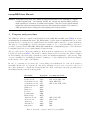
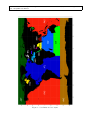
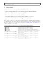
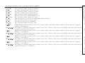
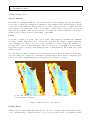
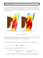
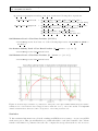
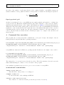
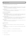
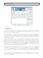
File: SO-UM-BEC-0007-remapISEA-0.3.pdf , version 1.0
Title: remapISEA User Manual.
Institution: SMOS Barcelona Expert Centre, ICM-UTM-CSIC / UPC
Authors: Justino Martı́nez.
Contact: [email protected]
Date: 06/03/2012
File: SO-UM-BEC-0007-remapISEA-0.3.pdf
Version: 1.0
Date: 06/03/2012
Page: 1 of 14
remapISEA User Manual.
Abstract: remapISEA interpolates some SMOS georeferenced products to be expressed in a regular
latitude-longitude grid. The resulting netCDF file contains the desired SMOS products
fields expressed as a function of latitude and longitude. This file can also include helpful
information about the interpolation process for each interpolated variable: The number of
ISEA grid points used to interpolate each resulting value and its variance.
1
Purpose and procedure
The SMOS products are computed and distributed in the ISEA 4H8 and 4H9 grids [DEI04] as well as
in 100x100 km and 200x200 km grids. The ISEA family of grids ensures a minimum distortion of the
areas in the globe, but the most popular libraries and software still are unable to operate with them.
The purpose of remapISEA is to provide a fast and confidence tool to convert the SMOS georeferenced
products, expressed in the ISEA 4H9, ISEA 4H8, 100x100 km or 200x200 km grids, to the well known
rectangular grids based on a regular latitude-longitude mesh.
The procedure used to interpolate SMOS products from their original grid to the desired regular latlon grid is described in [MB11]. The method of interpolation is based on average the values contained
in each resulting cell but keeping, as much as possible, the statistical significance of the average. This
one is accomplished by expanding the distance of influence of each original grid point along longitude
as the inverse of the cosine of the latitude.
In case of converting sea products, the corresponding sea identification for each cell is activated
internally. In this case, for a given cell, only grid points that belong to seas connected to the sea of
the cell are included to compute the average in this cell. Table 1 and map 1 show the predefined seas,
their limits and the connection among them.
Sea name
Atlantic Ocean
Pacific Ocean
North Indic Ocean
South Indic Ocean
Mediterranean Sea
Baltic Sea
Black Sea
Red Sea
Persian Gulf
Hudson Bay
Antarctic Ocean
Arctic Ocean
Japan Sea
Arabian Sea
Bengal Sea
Acronym
ATL
PAC
NIN
SIN
MED
BAL
BLA
RED
PER
HUD
ANT
ARC
JAP
ARA
BEN
is connected with...
SIN, ANT, ARC
SIN, ANT, ARC, JAP
ARA, BEN,SIN
ATL, PAC, ANT, NIN
ATL, PAC, SIN
ATL, PAC
PAC
NIN
NIN
Table 1: Seas and oceans recognised by remapISEA
File: SO-UM-BEC-0007-remapISEA-0.3.pdf
Version: 1.0
Date: 06/03/2012
Title: remapISEA User Manual.
Figure 1: Seas limits and acronyms
Page: 2 of 14
File: SO-UM-BEC-0007-remapISEA-0.3.pdf
Version: 1.0
Date: 06/03/2012
Page: 3 of 14
Title: remapISEA User Manual.
2
The products
RemapIsea can convert to lat-lon grid the following SMOS products:
• Browse Brightness Temperature L1 data (BWLF1C/BWSF1C/BWSD1C/BWLD1C)
• Sea Surface Salinity Level 2 User Data Product (OSUDP2)
• Soil Moisture Level 2 User Data Product (SMUDP2)
• Sea Surface Salinity Level 3 User Data Product (M
• Soil Moisture Level 3 User Data Product (M
Oxxxxn n = {1, 3, 4, 5})
Lxxxxn n = {1, 3, 4, 5})
These ones are georeferenced products and the resulting netCDF file contains dimensions lat (latitude)
and lon (longitude). The extracted fields are expressed as functions of these dimensions. The fields
that can be extracted from products are the following (see [IND10], [IND11] and [GMV11] for a
complete description of these fields):
Browse Brightness Temperature L1 data (BWLF1C/BWSF1C/BWSD1C/BWLD1C).
Altitude
Local altitude taken from GETASSE30
BT Value HH
Brightness Temperature. HH polarisation
BT Value VV
Brightness Temperature. VV polarisation
BT Value ReHV
Brightness Temperature. Real part of HV polarisation
BT Value ImHV
Brightness Temperature. Imaginary part of HV polarisation
Pixel Radiometric Accuracy HH
Error accuracy measurement in Brightness Temperature.
HH polarisation
Pixel Radiometric Accuracy VV
Error accuracy measurement in Brightness Temperature.
VV polarisation
Pixel Radiometric Accuracy ReHV Error accuracy measurement in Brightness Temperature.
Real part of HV polarisation
Pixel Radiometric Accuracy ImHV Error accuracy measurement in Brightness Temperature.
Imaginary part of HV polarisation
File: SO-UM-BEC-0007-remapISEA-0.3.pdf
Title: remapISEA User Manual.
Version: 1.0
Date: 06/03/2012
Sea Surface Salinity Level 2 User Data Product (OSUDP2).
SSS1
Sea Surface Salinity using roughness model 1
Sigma SSS1
Theoretical uncertainty computed from SSS1
SSS2
Sea Surface Salinity using roughness model 2
Sigma SSS2
Theoretical uncertainty computed from SSS2
SSS3
Sea Surface Salinity using roughness model 3
Sigma SSS3
Theoretical uncertainty computed from SSS3
A card
Effective Acard retrieved with minimalist model
Sigma Acard
Theoretical uncertainty computed for Acard
WS
10m neutral wind module derived from ECMWF UN10 and VN10
Sigma WS
Theoretical uncertainty associated to WS
SST
Sea Surface Temperature from ECMWF
Sigma SST
Theoretical uncertainty associated to SST
Tb 42 5H
Brightness Temperature at surface level for 42.5◦ incidence angle derived with default forward model and retrieved geophysical
parameter. H polarisation
Sigma Tb 42 5H Uncertainty for brightness Temperature at surface level for 42.5◦ incidence angle derived with default forward model and retrieved
geophysical parameter. H polarisation
Tb 42 5V
Brightness Temperature at surface level for 42.5◦ incidence angle derived with default forward model and retrieved geophysical
parameter. V polarisation
Sigma Tb 42 5V Uncertainty for brightness Temperature at surface level for 42.5◦ incidence angle derived with default forward model and retrieved
geophysical parameter. V polarisation
Tb 42 5X
Brightness Temperature at surface level for 42.5◦ incidence angle derived with default forward model and retrieved geophysical
parameter. X polarisation
Sigma Tb 42 5X Uncertainty for brightness Temperature at surface level for 42.5◦ incidence angle derived with default forward model and retrieved
geophysical parameter. X polarisation
Tb 42 5Y
Brightness Temperature at surface level for 42.5◦ incidence angle derived with default forward model and retrieved geophysical
parameter. Y polarisation
Sigma Tb 42 5Y Uncertainty for brightness Temperature at surface level for 42.5◦ incidence angle derived with default forward model and retrieved
geophysical parameter. Y polarisation
Page: 4 of 14
File: SO-UM-BEC-0007-remapISEA-0.3.pdf
Version: 1.0
Date: 06/03/2012
Page: 5 of 14
Data Product (SMUDP2).
Local altitude taken from GETASSE30
Retrieved soil moisture value
DQX for Soil Moisture
Nadir optical thickness estimate for vegetation layer
DQX for nadir optical thicknes
Surface temperature
DQX for surface temperature
Optical thickness coefficient for polarisation H
DQX for TTH
Ratio of optical thickness coefficients TTH/TTV
DQX for RTT
Scattering albedo for horizontal polarisation
DQX for scattering albedo
Difference of albedos Wh-Wv
DQX for difference of albedos
Roughness parameter estimate
DQX for roughness parameter estimate
Real part of the dielectric constant from MD retrieval
DQX for real part of the dielectric constant from MD retrieval
Imaginary part of the dielectric constant from MD retrieval
DQX for imaginary part of the dielectric constant from MD retrieval
Real part of the dielectric constant from retrieval models other than MD
DQX for real part of the dielectric constant from retrieval models other than MD
Imaginary part of the dielectric constant from retrieval models other than MD
DQX for imaginary part of the dielectric constant from retrieval models other than MD
Surface level brightness temperature computed from forward model. Incidence angle 42.5◦ . H polarisation
DQX for surface level brightness temperature computed from forward model. Incidence angle 42.5◦ . H polarisation
Surface level brightness temperature computed from forward model. Incidence angle 42.5◦ . V polarisation
DQX for surface level brightness temperature computed from forward model. Incidence angle 42.5◦ . V polarisation
Top of atmosphere brightness temperature computed from forward model. Incidence angle 42.5◦ . H polarisation
DQX for top of atmosphere brightness temperature computed from forward model. Inc. an. 42.5◦ . H polarisation
Top of atmosphere brightness temperature computed from forward model. Incidence angle 42.5◦ . V polarisation
DQX for top of atmosphere brightness temperature computed from forward model. Inc. an. 42.5◦ . V polarisation
Title: remapISEA User Manual.
Soil Moisture Level 2 User
Altitude
Soil Moisture
Soil Moisture DQX
Optical Thickness Nad
Optical Thickness Nad DQX
Surface Temperature
Surface Temperature DQX
TTH
TTH DQX
RTT
RTT DQX
Scattering Albedo H
Scattering Albedo H DQX
DIFF Albedos
DIFF Albedos DQX
Rougness Param
Rougness Param DQX
Dielect Const MD RE
Dielect Const MD RE DQX
Dielect Const MD IM
Dielect Const MD IM DQX
Dielect Const Non MD RE
Dielect Const Non MD RE DQX
Dielect Const Non MD IM
Dielect Const Non MD IM DQX
TB ASL Theta B H
TB ASL Theta B H DQX
TB ASL Theta B V
TB ASL Theta B V DQX
TB TOA Theta B H
TB TOA Theta B H DQX
TB TOA Theta B V
TB TOA Theta B V DQX
File: SO-UM-BEC-0007-remapISEA-0.3.pdf
Version: 1.0
Date: 06/03/2012
Page: 6 of 14
Title: remapISEA User Manual.
Sea Surface Salinity
SSS1
Var L2 SSS1
Anomaly SSS1
Error SSS1
Nr measurements SSS1
Reference SSS1
Error Reference SSS1
SSS2
Var L2 SSS2
Anomaly SSS2
Error SSS2
Nr measurements SSS2
Reference SSS2
Error Reference SSS2
SSS3
Var L2 SSS3
Anomaly SSS3
Error SSS3
Nr measurements SSS3
Reference SSS3
Error Reference SSS3
Background
Error Background
Level 3 User Data Product (M Oxxxxn n = {1, 3, 4, 5}).
Sea Surface salinity using roughness model 1
Variance of input SSS1 values contributing to the output SSS1 values
Difference between the absolute value and a predefined temporal mean
Theoretical uncertainty computed for SSS1
Number of input SSS1 values contributing to the output SSS1 values
Predefined mean value
Theoretical uncertainty of predefined mean value
Sea Surface salinity using roughness model 2
Variance of input SSS2 values contributing to the output SSS2 values
Difference between the absolute value and a predefined temporal mean
Theoretical uncertainty computed for SSS2
Number of input SSS2 values contributing to the output SSS2 values
Predefined mean value
Theoretical uncertainty of predefined mean value
Sea Surface salinity using roughness model 3
Variance of input SSS3 values contributing to the output SSS3 values
Difference between the absolute value and a predefined temporal mean
Theoretical uncertainty computed for SSS3
Number of input SSS3 values contributing to the output SSS3 values
Predefined mean value
Theoretical uncertainty of predefined mean value
Background Salinity Value
Error of the Background Salinity Value
File: SO-UM-BEC-0007-remapISEA-0.3.pdf
Version: 1.0
Date: 06/03/2012
Page: 7 of 14
Title: remapISEA User Manual.
Soil Moisture Level 3 User Data Product (M Lxxxxn n = {1, 3, 4, 5})
Altitude
Local altitude taken from GETASSE30
Soil Moisture
Soil Moisture (SM)
SM Var L2
Variance of input SM values contributing to the output value
Difference between the absolute value and
SM Anomaly
a predefined temporal mean
SM Error
Theoretical uncertainty computed for soil moisture
SM Reference
Predefined mean value
SM Error Reference
Theoretical uncertainty of predefined temporal mean
SM Nr measurements
Number of input values contributing to the output values.
Optical Thickness
Optical Thickness
OT Var L2
Variance of input Optical Thickness used values
OT Anomaly
Optical Thickness anomaly
Optical Thickness uncertainty
OT Error
OT Reference
Optical Thickness predefined mean value
Optical Thickness predefined mean value uncertainty
OT Error Reference
OT Nr measurements
Number of L2 Optical Thickness used values
Vegetation Water Content Vegetation Water Content
Soil Roughness
Soil Roughness
SR Var L2
Variance of L2 SR used values
SR Error
Soil Roughness uncertainty
SR Reference
Soil Roughness predefined mean value
SR Error Reference
Soil Roughness predefined mean value uncertainty
SR Nr measurements
Number of L2 SR used values
Dielectric Constant Real Real part of Dielectric Constant (DCR)
DCR Var L2
Variance of L2 DCR used values
DCR Anomaly
DCR anomaly
DCR Error
DCR uncertainty
DCR Reference
DCR predefined mean value
DCR Error Reference
Real part of Dielectric Constant predefined mean value uncertainty
DCR Nr measurements
Number of L2 DCR used values
Dielectric Constant Imag Imaginary part of Dielectric Constant (DCI)
DCI Var L2
Variance of L2 DCI used values
DCI anomaly
DCI Anomaly
DCI Error
DCI uncertainty
DCI Reference
DCI predefined mean value
DCI Error Reference
DCI predefined mean value uncertainty
DCI Nr measurements
Number of L2 DCI used values
3
Advanced issues
remapISEA takes some decisions automatically. Thus, the values for mesh size provided by the user
(-incLon and -incLat) are slightly modified if, according to the geospatial coverage of the product,
they don’t generate a grid with an integer number of cells. Another automatic decision concerns to
the connection between seas. As have been mentioned before, for a given cell which center belongs to
a given sea (see figure 1) only grid points that belongs to a sea connected to this one (see table 1) will
contribute to the average value of the cell.
Nevertheless, remapISEA admits some additional parameters that allow to the user to improve the
File: SO-UM-BEC-0007-remapISEA-0.3.pdf
Version: 1.0
Date: 06/03/2012
Page: 8 of 14
Title: remapISEA User Manual.
resulting remapped data.
Area of interest
By default, the resulting netCDF file covers the same region as the original product file. Nevertheless,
it is possible to change the resulting area defining the desired latitude and longitude ranges by means
of lat and/or lon parameters. These parameters accept two values separated by commas: The first
value stands for the initial value of the corresponding coordinate whereas the second one fixes its
final value. For instance -lat=-30,-20 -lon=-10,10 restricts the output netCDF file to the region
included in the rectangle defined by (30S, 10W ) − (20S, 10E).
Coast
Coast can be adjusted by means of the option -land. This parameter establishes the minimum
percentage of land contained in a cell to consider this cell as land. For example, -land=5 means that
cells containing a 5% of land or more, are considered as land. Note that, following this definition, sea
products will be void if -land=0 is defined. Therefore, in this case, remapISEA stops its execution
and warns about the convenience in increasing the value of land parameter. The default value of this
parameter is 10%.
Note that with low values of land some holes can appear in sea products (see figure 2). In the same
way, some values can be shown in oceans when converting land products. Don’t be surprised, these
zones corresponds to small islands that probably will not be drawn in your maps.
(a) Case with -land=5. Note the hole produced
by the small island of Bingaram
(b) Case with -land=95
Figure 2: Differences in the coast definition
Quality Flags
SMOS products contain quality flags that allows to the user to discard points in which the measures
or the computational processing have failed or not provide acceptable values. remapISEA is capable
File: SO-UM-BEC-0007-remapISEA-0.3.pdf
Version: 1.0
Date: 06/03/2012
Page: 9 of 14
Title: remapISEA User Manual.
to generate remapped products applying these quality flags (figure 3). By default no quality flags are
applied and all points included in the original product are used to recalculate the desired fields in the
new regular grid. In order to include only the points flagged as acceptable the flag -qualityFlags
must be included. The name of the original quality flags applied are stored as a global attribute in
the resulting netCDF file.
(a) Case with -qualityFlags.
Points with no quality are discarded
(b) No quality flags applyied.
All points present in the original product are included
Figure 3: Effect of qualityFlag tag
The presence of -qualityFlags flag imposes that a given grid point is only taken in consideration if
its failedFlag value is false. This flag depends on the original SMOS product and it is defined as
follows (see [IND10], [IND11] and [GMV11] for additional information):
Browse Brightness Temperature L1 product (BWLF1C/BWSF1C/BWSD1C/BWLD1C)
• failedFlag is true if RFI strong or RFI point are true
Sea Surface Salinity Level 2 User Data Product (OSUDP2)
• failedFlag is true if Fg ctrl poor geophysical or Fg ctrl poor retrieval are true
If the product was generated with a version of the L2 processor prior to 3.17 these flags are
not available. In this case, the previous definition is also applied but remapISEA calculates
File: SO-UM-BEC-0007-remapISEA-0.3.pdf
Version: 1.0
Date: 06/03/2012
Page: 10 of 14
Title: remapISEA User Manual.
Fg ctrl poor geophysical and Fg ctrl poor retrieval following these expressions:
Fg ctrl poor retrieval = Fg ctrl range + Fg ctrl sigma + Fg ctrl chi2 +
Fg ctrl chi2 P + Fg ctrl reach maxiter + Fg ctrl marq
Fg ctrl poor geophysical = Fg sc TEC gradient + Fg sc suspect ice + Fg sc rain +
Fg ctrl many outliers + Fg ctrl sunglint +
Fg ctrl moonglint + Fg ctrl gal noise +
Fg ctrl gal noise pol + Fg ctrl num meas low
Soil Moisture Level 2 User Data Product (SMUDP2)
• failedFlag is true if at least one of the following flags is true: FL NO PROD, FL RANGE or
FL Chi2 P
Sea Surface Salinity Level 3 User Data Product (M
Oxxxxn n = {1, 3, 4, 5})
• failedFlag is true if Fg Failed is true
Soil Moisture Level 3 User Data Product (M
Lxxxxn n = {1, 3, 4, 5})
• failedFlag is true if FL Failed is true
Figure 4: Zonal averages of number of points used to interpolate each cell in a SMOS salinity map (Sea Surface
Salinity Level 3 User Data Product remapped with a mesh size of 0.5◦ ). Green line stands for remapISEA
enhanced usual method whereas red line corresponds to -nocos flag activated case.
Statistics
To have statistical information stored in the resulting netCDF file it is necessary to execute remapISEA
with -stat option. This option will include two additional fields for each desired variable: One of them
stands for the number of points used in each cell to compute the average whereas the second one stores
File: SO-UM-BEC-0007-remapISEA-0.3.pdf
Version: 1.0
Date: 06/03/2012
Page: 11 of 14
Title: remapISEA User Manual.
the value of the variance of grid interpolation for the computed variable. remapISEA computes an
unbiased estimator of the population variance for interpolation of variable X following the expression:
2
SX
PN
=
Xi − X
N −1
i=1
2
Equal-populated grid
As has been mentioned before, remapISEA uses an equal-populated grid method to calculate the
average in each cell. This method assumes that the grid points contribute to cells located at a distance
which increases with the inverse of the cosinus of the latitude (see [MB11] for additional information).
This method allows an equal-populated grid even in zones close to the poles maintaining the statistical
significance of the average far from the equatorial zones. Nevertheless this method can be avoided
activating the flag -nocos. In this case, the grid points that contribute to the value assigned to a
cell are only those that are included in the cell itself (see figure 4 to compare both cases in a real
interpolation).
4
Command line execution
The program can be executed from the command line or as a part of script. An example of use in
Linux (64 and 32 bits) and Mac Intel operating systems is:
bin/remapISEA -input=data/SM_OPER_MIR_OSUDP2_20101121T192742_20101121T202143_316_001_1/
SM_OPER_MIR_OSUDP2_20101121T192742_20101121T202143_316_001_1.DBL
-output=salinity.nc -incLon=0.5 -extract=SSS3,WS -land=5 -stat -qualityFlags
remapISEA also runs in 32 bit Windows operating systems. In this case, an example of use could be:
C:\remapISEA\bin\remapISEA\.exe
-input=C:\data\SM_OPER_MIR_OSUDP2_20101121T192742_20101121T202143_316_001_1\
SM_OPER_MIR_OSUDP2_20101121T192742_20101121T202143_316_001_1.DBL
-output=salinity.nc -incLon=0.5 -extract=SSS3,WS -land=5 -stat -qualityFlags
The binary file to be executed is stored in the bin folder. The folder structure (bin and seasmask )
must remain unchanged to ensure a correct execution of the program.
Some mandatory parameters are needed to get a correct execution of remapISEA: .
MANDATORY PARAMETERS
-input= Product DBL file
Data Block file of the product to be remapped.
-output= netCDF file
Location and name of the resulting netCDF file
-extract= comma separated fields
List of fields to be extracted from the product file (see tables of section 2)
File: SO-UM-BEC-0007-remapISEA-0.3.pdf
Version: 1.0
Date: 06/03/2012
Page: 12 of 14
Title: remapISEA User Manual.
and the command line must include at least one of the following:
-incLon= degrees
Mesh size for longitude in the resulting grid. Minimum allowable value depends on the original
grid resolution (0.1 for ISEA 4H9, 0.2 for ISEA 4H8, 1 for 100x100 km and 2 for 200x200 km).
Default value: The value indicated by -incLat parameter.
-incLat= degrees
Mesh size for latitude in the resulting grid. Minimum allowable values have been indicated
above. Default value: The value indicated by -incLon parameter
OPTIONAL PARAMETERS
-lat= degrees,degrees
Comma separated values limiting the desired region latitude. If the first one is omitted −90 is
assumed as default value. If the second one is omitted 90 is assumed. If this parameter is not
included the latitude range coincides with the given by the original product.
-lon= degrees,degrees
Comma separated values limiting the desired region longitude. If the first one is omitted −180
is assumed as default value. If the second one is omitted 180 is assumed. If this parameter is
not included the longitude range coincides with the given by the original product.
-land= percent
Maximum land percentage in a sea cell.Cells with a land percentage higher than the by this
parameter are treated as land. Its default value is 10
OPTIONAL FLAGS
-stat
Computes the variance and the number of points used to interpolate each extracted field
-qualityFlags
Quality flags for the corresponding product are applied and only measures that pass the quality
test are considered
-nocos
A grid point only contributes to one cell, independently from its latitude.
-q
Quiet mode. remapISEA does not send any information to the standard output
-h
Shows quick help
-v
Shows version information
File: SO-UM-BEC-0007-remapISEA-0.3.pdf
Version: 1.0
Date: 06/03/2012
Page: 13 of 14
Title: remapISEA User Manual.
Figure 5: XBEC interface for remapISEA
5
XBEC GUI
In order to provide a friendly execution environment, remapISEA is accompanied by a GUI (Graphical
User Interface). This GUI is known as XBEC and it has been written in java allowing to be executed
from a wide variety of operating systems.
The XBEC GUI can be started in Linux systems by executing the shell script named remapISEA that
is located in the main folder of the application. In 32 bit Windows systems and Mac Intel systems the
graphical interface can be initiated by double clicking on the XBEC java application. The apperance
of XBEC is shown in figure 5.
The list of allowed fields that can be extracted is filled once the input product DBL file is provided.
This list is shown in the text area located at the bottom of the panel. In some operating systems the
DBL file can be dragged into the corresponding text field or selected from conventional files browsing.
To activate the execute remapISEA button it is necessary to give an output netCDF file name and
to select at least one field to extract. Once the execute remapISEA button is pressed the conversion
starts, the button is deactivated and the message Processing data... appears behind the button.
This message disappears when the resulting file is created.
The mesh size in the resulting grid is assumed as 0.5◦ but it can be changed to any value within
the allowable interval [αmin , 90.0) where αmin = 0.1◦ for ISEA 4H9, αmin = 0.2◦ for ISEA 4H8,
αmin = 1.0◦ for 100x100 km and αmin = 2.0◦ for 200x200 km). Also the maximum percentage in a
sea cell is assumed with its default value (10%) but it can be changed from 0% to 100% in intervals
of 5%
The optional flags -stat, -qualityFlags and -nocos described in the previous section can be activated by means of XBEC panel. Note that if the GUI is used, remapISEA will show error messages
but not information messages.
File: SO-UM-BEC-0007-remapISEA-0.3.pdf
Version: 1.0
Date: 06/03/2012
Page: 14 of 14
Title: remapISEA User Manual.
References
[DEI04]
DEIMOS. SMOS L1 Processor Discrete Global Grids Document SMOS-DMS-TN-5200,
June 2004. version 1.4.
[GMV11] GMV. SMOS CP34 Product Output Format Definition CP34-PS-0001, Sep 2011. version
2.9d.
[IND10]
INDRA. SMOS Level 1 and Auxiliary Data Products Specifications SO-TN-IDR-GS-0005,
Dec 2010. version 5.18.
[IND11]
INDRA. SMOS Level 2 and Auxiliary Data Products Specifications SO-TN-IDR-GS-0006,
May 2011. version 6.0.
[MB11]
J. Martı́nez and J. Ballabrera. Remapping isea grid to lat-lon grid in smos context. Technical
report, BEC-TN.2011.02.10 SMOS Barcelona Expert Centre, 2011.