1
_,--
:I
CAV!:
t
i,:
*Si~;ACMSRI
E,
I C*
CAM4MIDXE,
khnrr-
A
.A .F
m
<iW.EB
T
. L
ROOM 3¢5*e
I,
UKT SOr ,iC-j.4C
MASSAO tJu~ TS
I
:
OUY
9,;g
U .SA.
_
-
,#
_
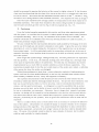
AN EXPERIMENTAL FACILITY FOR SEQUENTIAL DECODING
C. W. NIESSEN
h
imf
PA,
TECHNICAL REPORT 450
SEPTEMBER 13, 1965
MASSACHUSETTS
INSTITUTE OF TECHNOLOGY
RESEARCH LABORATORY OF ELECTRONICS
CAMBRIDGE, MASSACHUSETTS
I
The Research Laboratory of Electronics is an interdepartmental
laboratory in which faculty members and graduate students from
numerous academic departments conduct research.
The research reported in this document was made possible in
part by support extended the Massachusetts Institute of Technology, Research Laboratory of Electronics, by the JOINT SERVICES ELECTRONICS PROGRAMS (U.S. Army, U. S, Navy, and
U.S. Air Force) under Contract No. DA36-039-AMC-03200(E);
additional support was received from the National Science Foundation (Grant GP-2495), the National Institutes of Health (Grant
MH-04737-05), and the National Aeronautics and Space Administration (Grants NsG-334 and NsG-496).
The research reported in this document was also performed at
Lincoln Laboratory, a center for research operated by the Massachusetts Institute of Technology, with the support of the United
States Air Force under Contract AF 19(628)-5167.
Reproduction in whole or in part is permitted for any purpose
of the United States Government.
Qualified requesters may obtain copies of this report from DDC.
MASSACHUSETTS
INSTITUTE
OF
TECHNOLOGY
RESEARCH LABORATORY OF ELECTRONICS
Technical Report 450
LINCOLN LABORATORY
Technical Report 396
September 13, 1965
AN EXPERIMENTAL
FACILITY FOR SEQUENTIAL DECODING
C. W. Niessen
This report is based on a thesis submitted to the Department of Electrical Engineering, M. I. T., September 3, 1965, in partial fulfillment
of the requirements for the Degree of Doctor of Science.
Abstract
Sequential decoding is one of the few practical methods known for communicating over
a noisy channel which, for interesting rates, attains the error-correction capability predicted by Shannon's coding theorem. Since analytical investigations are limited by the
difficulty of the mathematics involved, experimental studies into the behavior of sequential decoding are necessary. This report describes the system design and implementation
of a facility for the experimental study of sequential decoding that may be used at M. I. T.
by graduate researchers in communications theory. Flexibility and ease of use are the
primary requirements of this system.
Thorough investigation of the characteristics of sequential decoding and likely problems to be studied led to a system based upon the Project MAC PDP-6 computer. The
design reflects constraints imposed by time, cost, equipment availability, and the anticipated class of users. A portable data-acquisition system, consisting of a digital tape
recorder and analog-to-digital conversion equipment, is provided to make available to the
computer the outputs of experimental demodulation equipment.
The experimenter can
decode the acquired data sequentially in accordance with an algorithm specified and easily written by him in a version of Fortran modified for this purpose.
The modified
Fortran contains statements for the use of special subroutines provided, such as a convolutional coder. The program is run within a monitor system which handles most inputoutput automatically and provides for man-machine interaction with the program. The
monitor also collects statistics on the decoding process to aid the user in evaluating his
algorithm.
All sequential decoding algorithms may ultimately be described as tree search
rithms in which it is desired to find the "best" path through a tree. A display of the
searched by the algorithm has therefore been made the principal tool for the
machine interaction. The user watches this display and controls the running of the
rithm via a light pen and commands typed to the monitor.
algopaths
manalgo-
The system has been successfully implemented and tested, and experimental results
are described.
I`
I
TABLE OF CONTENTS
I.
II.
III.
IV.
V.
SYSTEM DESIGN AND OBJECTIVES
1
A.
Introduction
1
B.
Description of Sequential Decoding
1
C.
System Design Considerations
8
DATA-COLLECTION
SYSTEM
11
A.
Form of Input
12
B.
Recording Equipment
12
C.
Restrictions on Channels
13
D.
Hardware for Playback
14
E.
Ordered Lists
14
F.
Programs for Ordered Lists
15
OPERATING
16
SYSTEM
A.
Available Subprograms
16
B.
Output Display
20
C.
Monitor System
23
SPECIAL
LANGUAGE
25
A.
Requirements to Describe Algorithm
25
B.
Requirements to Manipulate Coder
26
C.
Requirements to Control Display
27
D.
Requirements to Reference Input Data
27
E.
Requirements to Collect Statistics
28
EXAMPLES,
TESTS AND CONCLUSIONS
28
A.
Example Chosen
28
B.
Example of Display
30
C.
Example of Statistics
33
D.
Conclusions
34
APPENDIX AI.
II.
37
User's Manual
Introduction
37
Data Collection
37
III.
Ordered List Formation
38
VI.
Writing the Algorithm
40
V.
Running the Programs
60
APPENDIX B - Data-Collection System
67
APPENDIX C - Display of Tree
69
APPENDIX D - Syntax-Directed Compiler
72
Acknowledgments
75
References
76
iii
I
AN EXPERIMENTAL FACILITY FOR SEQUENTIAL DECODING
I.
SYSTEM DESIGN AND OBJECTIVES
A.
Introduction
In 1948,
C. E. Shannon published the fundamental paper
which first proved the existence of
methods for making as small as desired the probability of error in the reception of signals distorted by noise.
This result, called the coding theorem, holds true only so long as the rate of
transmission is less than a particular value (known as channel capacity) which is determined
by the statistical characteristic of the noise.
Unfortunately,
attempts to realize systems meeting
the performance predicted by the coding theorem have been largely unsuccessful,
since all the
obvious implementations require either an extremely large amount of receiving equipment or
an exceedingly long time to process the received signals.
To date,
sequential decoding 2 ' 3 is one of only two processes (the other is that of Forney 4 )
which have shown promise of attaining the results predicted by the coding theorem while still
using only a reasonable amount of terminal equipment and processing time.
Because of mathematical difficulties encountered in trying to analyze the properties of
sequential decoding, in some cases it seems more profitable to study the process experimentally.
This can be done either by constructing equipment to perform sequential decoding, by simulating
such equipment on a digital computer,
or by a combination of both of these.
The objective of designing and implementing an experimental facility for the study of sequential decoding has been a challenging problem in system design, which at many stages has required
detailed comparison of several alternative ways to implement the system.
A design problem of
this nature is never a "pure" one; it always involves constraints imposed by many factors such
as time, money, availability of equipment and, above all, the characteristics of the process to
be studied and the problems to be investigated with the system.
This report not only describes the system which was finally implemented, but indicates the
alternatives that were available and the reasons behind the choices that were made.
Before
discussing the details of the system, it is necessary to look closely at the process of sequential
decoding.
We assume that the reader is familiar with the basic concepts of error-correcting
codes and modern communications theory, which will be used freely.
For a background refer-
ence, we recommend Wozencraft and Jacobs.5
B.
Description of Sequential Decoding
1.
Coding and Decoding
Sequential decoding refers to a class of error-correcting coding/decoding methods which
may be used to communicate data over a communications channel with extreme reliability,
i
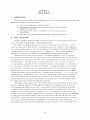
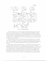
N BRANCHES
13-6Z-3661
2 NODES
V
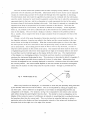
f
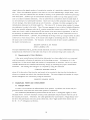
Fig. 1. Tree structure of information bits.
1
13-62-36621
/-RIT SHIFT RFGISTER
m
2
CHANNEL WAVEFORMS
Fig. 2. Convolutional encoder.
2
despite the presence of a random disturbance on the channel.
To be specific, let us consider
the problem of communicating a string of statistically independent equiprobable binary digits
generated by some hypothetical data source.
The channel is assumed to be memoryless, and
communication is carried on by sending a sequence of waveforms over the channel.
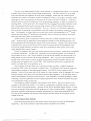
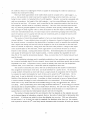
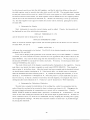
consider a string of N bits from the source.
tions (called messages),
In particular,
These N bits can be any of 2N different combina-
and the sequences can be represented in the form of a tree (Fig. 1),
where the tree is of depth N and has 2N terminal branches, one for each message.
To send a
message, the transmitter might use the channel N times, each time sending one of the binary
digits along the path through the tree corresponding to the desired message by sending one of
two waveforms over the channel.
However,
because of noise in the channel, the receiver will
occasionally make a mistake on one or more digits.
When such a mistake is made, the output
of the receiver is a string of binary digits which is exactly like some message other than that
which was sent - the receiver will be unable to detect the fact that an error has been made.
To combat the noise on the channel,
a coding process is employed.
mitter may first be changed so that it is able to send M = 2
stead of just 2.
For example,
the trans-
(m > 1) different waveforms in-
The coding may consist of assigning a signal chosen from this set of M (call
it {s}) to each of the branches in the tree.
In order to send a particular message, the trans-
mitter then sends the sequence of waveforms assigned to the path through the tree corresponding
to the desired message.
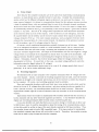
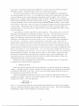
A particularly simple implementation of this assignment procedure is
that of a convolutional or shift-register encoder.
the last v binary digits from the source.
In this device (Fig. 2), the shift register holds
Each time the assignment for the next branch in the
tree is needed, the information bit for that branch is shifted into this register (which already
contains the last v digits describing the path through the tree to this node).
Then m parity
nets form the sum modulo 2 of the bits of the shift register to which the adder is connected.
(This matrix of connections therefore specifies the code.)
The m binary digits generated by the
parity nets is an m-bit binary number which selects one channel waveform from the set of
2m = M signals.
With this encoding method, if an error is made at the receiver (which must
have a "copy" of the tree and the assignments made to each branch), hopefully the received
sequence will not be identical to any of the other paths through the tree, but will appear to be
"closest" in some sense to the correct path.
Now we must define some function for measuring the "closeness" of the received signals
and the allowed message sequences.
r = (ri,
r 2 ...
Let us denote the sequence of N received signals by
rN), the N information digits of message i by mi = (mi, mi2.
.
. miN), and the
corresponding sequence of transmitted waveforms by si = (sil, si2, ..
SiN ) .
the path through the tree which maximizes Pr(r Lmi), hence Pr(r|
Ideally, then, what the
receiver should do is compute all 2N of the numbers Pr(r
a very large number if N
si).
Suppose we choose
si) and pick the largest.
But 2N is
50, say, and such a huge amount of computation is clearly impractical.
We must find some other method.
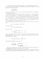
As a preliminary, when we assume that the N successive
uses of the channel are statistically independent,
we may write
N
Pr(rsi )=
ii
Pr(rnlin)
(1)
n=l
and, instead of maximizing this over {Si}, maximize
3
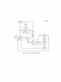
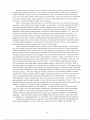
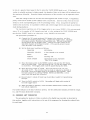
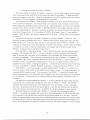
Fig. 3.
Word flow chart of Fano algorithm.
4
LN(i)=
)
log Pr(r si
N
=
E
logPr(rn sin)
n=l
N
=
in
(2)
n=1
over {si}.
In this form, we see that the total "closeness of fit" between the received signal and
each path through the tree is the sum of the measures of the closeness of fit (in)
for each branch
in the tree along the path corresponding to s i .
It is this form which suggests the possibility of using a tree search algorithm to find the
best path through the tree, i.e., the best s..
i
The receiver will move forward through the tree,
one branch at a time, keeping a running total of the increments (in)
along the path leading from
the origin to the current position in the tree. If the algorithm chooses the correct path, this
k
number, Lk(i)
=
Xin, should become more negative only slowly as k increases.
Along an
n=l
incorrect path, however, it should grow negative rapidly. By observing the behavior of Lk, an
algorithm can make a decision whether to continue moving forward through the tree, or whether
to back up and try some other path.
Just what rules are used to determine when to back up de-
pend on the details of the particular algorithm.
In the example discussed above, the tree was binary (it had two branches stemming from
each node) because each branch represented one information bit.
node can be constructed by assigning v
Trees with 2 0 branches per
information bits to each branch.
Also, the assignment
may be such that a sequence of p. channel symbols is assigned to each branch of the tree instead
of just one.
In addition, the restriction to a memoryless channel can be eliminated by changing
the tree structure through which the decoder searches.
In the example discussed above, this
tree was the same as the tree generated at the transmitter;
but, for a time-variant channel,
the tree structure at the receiver might be changed so that at each node there would be a branch
for every combination of information bits and channel state, instead of just for every combination
of information bits.
Thus, there are many quite different communication problems to which
sequential decoding is applicable,
and all have the common characteristic of being tree search
algorithms.
2.
Example of an Algorithm
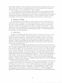
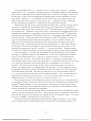
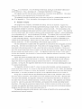
To clarify later discussions and to provide an example which will be used throughout this
report, we will describe in detail the particular sequential decoding algorithm (shown as a flow
chart in Fig. 3) which is a variation by Jacobs and Wozencraft
Fano.
of an algorithm described by
3
This algorithm uses a decision criterion which may be represented as a horizontal line in
a plot of total "metric" vs depth in the tree.
of the "threshold increment" T o .
This "threshold" may take on only integer multiples
Instead of the Xin of Eq. (),
the
hypothesis (on a tree with one channel use per branch) is defined as
t This is not a true metric in the strict mathematical sense.
5
metric"t
used for each
Xin =log
Pr(r S nI
n
Pr(r )
-R
(3)
where n is the node depth, rn is the received data about the branch at this depth, and sin is the
signal associated with the branch in question.
R (which equals vo ) is the information trans-
mission rate in information bits per branch, and serves as a "bias" that causes the total metric
along a typical incorrect path to decrease on the average, and the total metric along the correct
path to increase.
Thus, a plot of metric vs node depth along the correct path should be a line
which has an average positive slope, despite occasional dips which are caused by the noise in
the channel.
The algorithm searches the tree in the following manner.
It evaluates X.in for all i (all
branches) at the current node (at depth n) and orders them numerically.
(The one with the
highest value is that which is a posteriori most
likely.)
The algorithm then adds this "best" Xn
-~~~~~~~~~~~~~~~~~in
to the total metric L, and checks to see if this new value of L is at least equal to the current
value of the threshold T.
next node.
If so, the algorithm accepts this branch and advances along it to the
The algorithm then increases the threshold by as many increments of To as it can
and still keep L > T.
This process continues until some "best" branch has a negative value
which causes the total metric to fall below the current value of the threshold.
When this occurs,
the algorithm begins to search the tree for a better path.
Actually, the threshold may be violated for two reasons:
either the decoder was on the right
path all the time but a bad period of noise on the channel caused the metric along the right path
to fall, or the decoder made a wrong turn at some previous node but the error was not detected
until now because noise on the channel made the bad path look good.
The decoder responds to this threshold violation by searching all paths leading from all
previously searched nodes which lie above the threshold to see if any of these paths remain above
the threshold.
It does this by backing up one branch at a time (without changing the threshold)
and exploring all other paths leading from this node until each falls below the threshold.
Note
that the decoder does not actually look at all of them- if the jth most likely branch at a node
falls below the threshold, so must the j + 1 th, etc., so there is no point in looking at any of
these.
Eventually, the coder backs up (along the original path) to a point which lies below the
threshold.
At this point, it has searched all paths leading from this node and has found that
they all eventually fall below the threshold.
The decoder then lowers the threshold to T' = T - T
0
and begins to search all these paths again, just as if it had never seen any of them before.
The
difference is that this time the decoder will not allow the threshold to be raised again until it
arrives at a new node, one it has never reached before.
However, it has searched all the paths
leading from the current node until they fell below T; thus, any new node must be one which
lies on an extension of these paths at a point below T and, of course, if it is to be successful,
above T' = T - To . Only after the decoder finds one of these new nodes does it allow the threshold to be raised again, when it advances successfully beyond this node. This control over the
threshold is maintained by means of a flag F in the algorithm. It is set to 1, thereby inhibiting
the threshold from being raised, whenever a path which has been tried fails.
The flag is cleared
to 0, allowing the threshold to be increased as needed, when the decoder finds one of the new
nodes, i.e., the nodes lying less than T above the current threshold.
6
Should all paths (even the new ones) fall below the new threshold, the decoder will again
work its way back to a point on the original path which is below the new threshold, reduce the
threshold by To , and try again.
In this manner, the decoder will successively reduce the thresh-
old until either the metric along the correct path stays above this threshold,
or the point on the
current path where a wrong choice was made is brought above the threshold,
allowing the correct
path to be searched.
Of course, this decoding process need not stop after N branches.
a path through the tree to be of indefinite length;
cedure.
The coding method allows
hence, the decoding is also a continuous pro-
We must now decide when the information bits corresponding to the path taken through
the tree will be given out by the decoder.
Since analysis indicates that the probability of searches
requiring a backup of more than 2v or 3v branches is very small,
one possibility is to consider
The
a decision at a node final after the decoder advances 2v or 3v branches beyond this point.
information bits for this branch are then said to be "decoded" and are put out by the decoder.
3.
Why Sequential Decoding Is of Interest
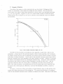
The reason that sequential decoding is of practical interest is the fact that the average number of branches looked at in order to decode one branch (called the average number of computations) is a finite quantity which is independent of v,
so long as the rate of transmission (in infor-
mation bits/channel symbol) is less than some number Rcomp which is characteristic of the
channel and the modulation/demodulation system used.
The number Rcomp is,
than channel capacity, but for many channels it is a sizable fraction of capacity.
of course, less
In contrast,
the number of computations to decode a branch in a tree using a coder with shift register of
length v is exponential in
v when all paths in the tree must be searched to depth v/v
This
o .
reduction in the amount of work done to decode N branches is paid for by the fact that the actual
number of computations is a random variable.
Practical considerations require a closer in-
vestigation of the behavior of this random variable,
since a receiver must have a finite buffer
memory of some sort in which to remember the received data until the decoder is ready for it.
If the decoding algorithm should take too long in searching a section of the tree, the buffer might
fill up and there would be no place to store incoming data, resulting in complete breakdown of
communications.
The error-correction capabilities of the sequential decoder are also bf interest.
It can be
shown that the probability that the decoder will make a mistake on an information bit, and still
succeed in getting back on the right path (by getting v correct information bits into the shift
register) without correcting the mistake, decreases exponentially with v, the same exponential
behavior with v long known for block decoding.
4.
Need for Experimental Study of Sequential Decoding
The communications analyst interested in sequential decoding is faced with computing
quantities such as the distribution of the random variable of number of computations, the probability of buffer overflow, and the probability that the decoder will advance N nodes beyond a
point in the tree where it made a wrong turn and still not detect the error.
quantities to analyze;
memoryless channels.
These are difficult
but a good deal of progress has been made, particularly for discrete,
6
Some extensions to time-varying channels have also been made.
Never-
theless, many cases of interest have not been analyzed, and for each particular case there are
7
numerical constants in the algorithm which must be optimized.
Further, most of the results
obtained by analysis are in the form of bounds on the quantity of interest, bounds which are correct in their exponential behavior but not tight to within constants.
Much greater accuracy than
is provided by analysis is required for the actual design of equipment for sequential decoding.
For solution of such problems, computer simulation of the decoder is very useful.
Another important area for investigation is the design of new sequential decoding algorithms.
Here again, experimental investigation would be very useful.
C.
System Design Considerations
1.
Preliminary System Specifications
From the previous description of sequential decoding,
coder can be broken into four parts.
it should be clear that any such de-
The first part we shall call the signal processor;
it takes
as its input the set of voltages produced by the receiver each time the channel is used, and converts these voltages to a digital representation which is stored away in a buffer memory until the
decoder is ready for the data.
The second part of the decoder is the convolutional coder,
which
is identical to the one in the transmitter and is used to generate the signal assignments made to
each branch of the tree.
The third part of the decoder is the metric evaluator, which computes
the metric increments associated with each branch at the node in the tree where the algorithm
is in its search.
The inputs to the metric evaluator are the signal assignments made to the
branches at this node (supplied by the convolutional coder) and the data about the received signal
for this branch (supplied by the signal processor).
With the information provided by the metric
evaluator, the fourth part of the decoder executes the particular sequential decoding algorithm
desired and decides on which branch to advance or whether to back up in the tree.
The capabilities required of each of these four elements of the decoder are determined by
the types of experiments which are likely to be of interest.
Although it is impossible to specify
in advance all the problems that will be studied using this system, a crucial part of the system
design is the thoughtful anticipation of many modes of investigation and the insurance that each
element of the decoder is flexible enough to handle them.
Once the capabilities of each part are
determined, the details of implementing each of them can be studied.
First of all, what are the general types of experiments to be performed?
Certainly,
evalua-
tion of operating characteristics and optimization of parameters in the algorithm will be done
for particular algorithms and channels.
Another more difficult class of problems involves the
invention of new decoding techniques (for example, finding some way to reduce the variability
of the number of branches looked at in order to reduce the probability of buffer overflow).
A
further problem of this type would be to find ways to resynchronize the decoder (get it back on
the right path) once buffer overflow has occurred.
Extending present algorithms so that they
will work on a broader class of channels, particularly time-variant channels, will also be important.
As suggested previously, this would probably be done by changing the decoding tree
structure (and therefore the algorithm) to include a hypothesis on the state of the channel as
well as on the information bits.
The experimental facility will also be useful in studying modulation techniques for coding
on channels of various types.
In particular, both time-variant and time-invariant narrow band-
width channels with a high signal-to-noise (S/N) ratio need to be studied.
Also of interest will
be wide bandwidth channels with low S/N ratios.
8
I
Although not exhaustive,
the scope of the experimentation anticipated above is sufficiently
great that a facility flexible enough to handle these problems may be expected to be flexible
enough to cope with a large variety of other problems as well.
2.
Preliminary Design Decisions
Before it is possible to go any further in the system design, it is necessary to make some
preliminary decisions about the form of the system.
While for clarity of presentation the de-
cision process may seem to be linear (with one decision leading to another), this is not so.
There is a tremendous amount of interaction between decisions.
made in this section depends on all its consequences,
later.
The ultimate value of a decision
which may not be apparent until much
Although one might be tempted to describe the decision process as having a tree struc-
ture itself, with a few early decisions each leading to many later, more detailed decisions, this
would neglect the interactions of these smaller decisions with others seemingly far removed.
The best design procedure seems to be partly trial and error:
making decisions and carrying
out their consequences until inconsistencies or difficulties appear, and then, in the light of new
knowledge,
revising the original decisions.
A very basic decision that must be made early in the system design is how much of the total
communications system the experimental facility should attempt to provide.
Since each channel
and each modulation technique is unique, it would be difficult to design equipment to handle all
cases of interest.
Furthermore,
we are unable to model mathematically (hence, to simulate)
most interesting channels, and there is already a good deal of experimental work in modulation/
demodulation techniques being performed at M.I.T.
perimental facility should require,
real communications systems.
For these reasons, we decided that the ex-
as its main form of input, the outputs of demodulators in
Since these outputs are precisely the inputs to the signal-
processor portion of the sequential decoder, this decision means that the experimental facility
need provide only that part of the communications system which is the actual sequential decoder.
Given this decision, a way must be found to make the output of the demodulation equipment
available as the system input.
Since it is unlikely that any way can be found either to bring the
demodulator to the sequential decoding system or vice versa, it seems that some kind of portable
data-gathering and recording equipment is a necessary part of the experimental system.
This
data-collection system must record all the significant outputs of the demodulator for any of
many different channels, probably on magnetic tape.
the experimental facility.
This tape must then be played back into
The design of this data-acquisition system and the system considera-
tions affecting it are detailed in Sec. II.
The choice of ways to realize the system now comes down to either building special-purpose
equipment or simulating it on a general-purpose digital computer, or some combination of the
two.
The only decision obvious at the start is that, if the experimental facility is to study dif-
ferent algorithms,
it is unlikely that special equipment could be built for executing the algorithm
that would permit sufficient flexibility.
This means that a general-purpose digital computer
must be the heart of the system and that the algorithm will be programmed into the computer.
Arguments as to whether the coder, distance evaluator and signal processor should be
software or hardware now revolve around whether hardware implementation can increase the
operating speed of the system sufficiently to justify the (obviously) higher initial cost.
This is
likely to be the case only if one or more of the sections of the system required an amount of
9
computation many times greater than that required to execute the programmed algorithm.
(It
should be noted that the computer will obviously also be used to collect statistics on the decoder
and output these results, resulting in a further amount of computation time required of the
computer, thus biasing the decision even more in favor of the software system.)
It should also
be remembered that interfacing special-purpose equipment with a large computer system presents a host of problems, both technical and administrative.
Preliminary speed calculations,
as outlined above, were made early in the system design,
but to go into the details here would distract from the main lines of thought.
Suffice it to say
that the problems just mentioned, particularly the large initial cost, made it clear that the
construction of special-purpose equipment would be unprofitable.
There are constraints imposed on the experimental facility other than just its capability of
performing experiments of interest.
How the system is implemented determines its usefulness
quite as much as its capabilities do.
In the early stages of system design, it is useful to study
previous related work and benefit from experience already gained.
Fortunately,
some of the
requirements for making our system useful were pointed out by previous experience with computer simulation of sequential decoding.
A great deal of simulation was performed at Lincoln Laboratory,
construction of both SECO
and Jordan.10
7
8 9
and LET. '
prior to the design and
One report on this simulation work is that of Blustein
This simulation included both the channel and the decoder,
study one particular algorithm.
and was intended to
From the experience gained at Lincoln, two conclusions can
be drawn about an entirely programmed system for studying sequential decoding.
First, simula-
tion is a useful tool which is capable of providing quite accurate answers to specific problems,
such as optimization of parameters in an algorithm and measurement of the statistical behavior
of the decoding process.
gramming effort.
Second,
simulation programs require a great deal of expert pro-
Each new problem to be investigated usually means revisions in a tightly
written machine-coded program.
While not too great a problem at Lincoln, such revisions
would be an entirely different matter at M.I.T., where the system is to be used by communications
students - not computer specialists.
The graduate student who is most likely to be responsible
for the programming probably is not an expert programmer, nor does he have the time to become one.
This problem suggests the need for some special programming language which would
be easy to learn and use.
The large investment of time required to get a simulation effort going
is often enough to discourage its use.
Furthermore,
it is difficult to make one person's program
useful to another person doing work in the same area but on a somewhat different problem.
While there may be many sections of their programming which do the same thing, format differences and lack of communication between the programmers make the likelihood of their using
the same programs small.
Clearly, the difficulty in the programming is not so much in describing the algorithm for
searching the tree as in the details of the programming.
Either the channel must be simulated,
or real data from some channel must be made available to the computer.
The decoder will need
to simulate a convolutional coder (not easily done in Fortran, for instance).
be put out concerning what the algorithm has done in searching the tree.
Information must
All these things re-
quire programming effort and much of it is I/O programming, which is particularly difficult
for an inexperienced programmer.
10
_
____
The aim of our experimental facility, based entirely on a programmed system,
is to provide
a system which will do many of these things automatically.
The user should have to do little
more than describe his algorithm in some special language,
which will also contain special
statements for control of a monitor system consisting of control, I/O program and other useful
subprograms which will simulate the functions of the coder and metric evaluator.
attention must be paid to the simplicity of the programming language,
learning effort.
Particular
in order to minimize the
At the same time, the compiler for this language must produce efficient code;
this is necessitated by the need to process large volumes of data to obtain statistically significant data about events of low probability.
Even so, collection of statistically significant
data on events of extremely low probability would still require an excessive amount of machine
For example, to collect data on an event which occurs with probability of 10
time.
require that more than 1012 branches be processed;
would
even at 100 sec per branch, this would
take more than three years of machine time!
Another obvious area of importance concerns the form of output available from the comPrinted output is sufficient for describing the statistics of the decoding process, but
puter.
seems inadequate for describing the details of the search process.
Clearly, this could be done
in tabular form, but such a form does not aid much in visualization of the decoding process.
The facility should therefore incorporate some form of graphical output which can be more
easily digested than reams of paper.
Choice of computers for use in the system involves several factors, among which availability
is of prime importance.
An IBM-7094,
operated in a time-sharing system,
was available at
Project MAC at M.I.T., but a major problem in the use of this machine was the fact that it is
being phased out and a new GE-635 is being introduced.
Thus, any part of the experimental
facility which would involve machine language programming would be obsolete when the new
machine goes into general use in early 1966.
This would have given time to implement the
system, but little time to run problems on it.
Also available at Project MAC was a somewhat smaller machine,
Corporation PDP-6 (Ref. 11) installed in October 1964.
long enough to perform all the experiments desired.
a Digital Equipment
The lifetime of this machine should be
The PDP-6 is by no means a small
machine - it has a 36-bit word with 16,000 words of 2-jLsec memory, plus 16 registers of 0.4-pLsec
flip-flop memory which serve as accumulators and/or index registers.
connect nonstandard I/O devices to this machine.
It is also quite easy to
Also available is an advanced display system
containing a character generator and line segment generator which would be excellent for graphical presentation of data in real time.
This brings up another desirable characteristic of the PDP-6, which was chosen as the
computer to be used in the system.
from the MAC time-sharing system.
It is used as a programmer-operated machine,
separate
Because of this and the excellent display facility, a whole
new area of operator interaction with the program as it runs is made possible, a feature which
was never available in the previous computer simulations on a batch-processing IBM-7094.
The uses of this capability will become more obvious when the details of the system are discussed in Sec. III.
II.
DATA-COLLECTION
SYSTEM
Given the decision that input to the system should come from the output of demodulation
equipment,
a way must be found to make these outputs available to the system.
11
.
II
_-
I*
I
-
I_
A.
Form of Input
Since data for the computer simulation are to be taken from experimental communications
systems,
we must decide upon a suitable format for such data.
Consider the communications
system which has M different orthogonal signal waveforms it can send over the channel.
many cases of interest,
it is shown in communications theory that the optimum receiver involves
a bank of matched filters,
with one matched filter for each of the allowable channel waveforms.
At the end of each use of the channel,
matched filter number "i" has at its output a voltage which
is monotonically related to Pr(r I si), the probability of the received signal r
number "i" was sent.
For
given that waveform
This set of M voltages then represents the total information attainable
at the receiver about each use of the channel.
If the waveforms are not orthogonal, less than
M matched filters will be needed, but the receiver would combine their outputs to produce M
voltages related to Pr(rl
i).
For more complex situations,
such as adaptive receivers which
estimate the characteristics of a time-variant channel, the objective of the optimum receiver
is still to produce a set of M voltages related to Pr(r I si).
Of course, not all modulation/demodulation methods of interest are of this type.
Sending
one of M orthogonal waveforms is useful on a wide bandwidth channel, but on a narrow bandwidth channel where the S/N ratio is high, something like amplitude (or phase) modulation of
one basic waveform might be used.
The output of the demodulator for this case might be a single
voltage which is an estimate of the amplitude (or phase) which was used at the transmitter.
The
signal processor should be capable of processing this voltage by storing it away as a digital
number.
Ultimately, however, the receiver should again relate the voltage produced by the
demodulator to Pr(r I si).
It is just that, in this case,
one output voltage suffices to carry the
information about the signal instead of M voltages.
In any event, restricting the system input to be a set of M voltages entails little loss of
generality,
B.
if M can be chosen sufficiently large.
Recording Equipment
We therefore seek to make available to the computer simulation these M voltages for each
use of the channel.
Clearly, some kind of recording equipment must be used,
since the receiver
can seldom be brought to the computer and the data rate of the receiver is seldom that required
by the computer.
Of course, any recording equipment must be portable.
Since real sequential decoders would most likely have some analog circuits which would be
driven by the set of M voltages from the receiver,
least
-percent accuracy,
and since analog circuits are capable of at
any recording system should have an equal accuracy.
Otherwise,
experimental results might be as much a function of the tape recorder as of the communications
channel.
Experiments which were made on multichannel FM recorders indicate that this accuracy is
barely attainable and only after elaborate alignment procedures.
It was therefore decided that
digital tape recording techniques offer the best means of preserving the data.
It was also decided very early that there was no point in trying to record data on
-in.
tape
in IBM format, since it would be impossible to adjust the timing of the communications system
so that data would be written on tape at the exact density required by IBM tape machines.
the recorder chosen need not write IBM compatible tapes.
then standard computer tape drives will not be able to read it.
must also be used to play the tape back into the computer.
12
__
Thus,
If the tape produced is nonstandard,
Therefore, the portable recorder
The list of portable digital tape recorders is quite limited.
After ruling out the very high
priced recorders intended for airborne or other mobile use, we selected a Precision Instrument
Company model PS-216-D recorder.
tion on a
-in.
tape (10½-in. reel).
This machine provides up to 16 tracks of binary informa-
The recorder will operate at tape speeds of
60
/2n in./sec
(n = 0 through 5), which provides for a wide range of speed compression between recording and
playback.
At 60 in./sec, one bit of data may be recorded on each track every 50 fsec.
It is an
important system consideration that this recorder is not capable of being started or stopped
quickly -the
time for these operations is 1 to 3 sec.
Analog-to-digital conversion equipment is required to change the voltages at the outputs of
the receiver into a form acceptable for the recorder.
Since all M receiver output voltages are
produced simultaneously, we must have M sample-and-hold (S-H) devices which will simultaneously sample these outputs.
An M channel multiplexer must then transfer each of these
voltages to an analog-to-digital (A-D) converter.
Each time a conversion is finished, the binary
output of the A-D converter is written out on tape as one word,
the next S-H unit.
and the multiplexer advances to
When all M signal values have been written on tape, a longitudinal parity
word is written on tape and then the equipment is ready to record the next use of the channel.
If M = 1, writing this longitudinal parity word would result in a low data density on the tape,
since every other word would be a parity word.
To improve this situation, the parity word may
be omitted if desired.
It would be desirable to have a large number of S-H units so that large values of M may be
used.
Unfortunately,
such devices are very expensive, so a compromise of ten was chosen.
Part of the rationale for this decision was that experimental modulation/demodulation systems
would not be built with more than ten matched filters, due to the amount of equipment required.
Moreover, for a narrow bandwidth channel of particular interest (the telephone line) when frequency orthogonal pulses are used, most of the inner-symbol interference results from frequencies located ±5 tones around any frequency of interest,
sufficient.
enough.
so ten output voltages would be
The A-D converter has an accuracy of 10 bits (0.1 percent),
which is more than
The additional accuracy of the A-D converter was obtained at very little extra cost and
will make the data-acquisition system useful for other purposes,
such as recording speech.
The logical design of the digital equipment used for recording was completed as part of this
report.
The detailed engineering and construction was done by Adage, Inc.
A more complete
description of the equipment will be found in Appendix B.
C.
Restrictions on Channels
The decision to provide only ten S-H units does place some restrictions on the system
capabilities.
In particular,
it would seem at first glance that the channel alphabet would be
restricted to <10; this is not necessarily so.
When the M channel waveforms are not orthog-
onal, fewer than M voltages can describe the receiver output; in some cases, ten may be
enough.
Also, when the channel is symmetrical,
i.e., all channel symbols are disturbed equally
by the noise, sending the all-zero information-bit sequence is equally as good as sending any
other message when performance criteria are to be measured.
the ability to record larger alphabets directly.
For example,
This fact sometimes leads to
in the case of M = 16 orthogonal
signals in white Gaussian noise, if the outputs for channel symbols 0 through 7 are recorded
13
when channel waveform 0 is sent, and then the same outputs are recorded again when no waveform is sent, this second set of eight outputs will have the same statistics as the outputs for
symbols 8 through 15.
Thus an alphabet of 16 may be simulated.
Use of nonsymmetrical channels presents another problem as well as restricted alphabet
size.
Since sending the all-zero information bit sequence may be an insufficient test, a real
convolutional coder may be required to generate the sequence of channel symbols corresponding
to the particular sequence of information bits used.
For the symmetrical channel, the coder
is not needed, since the zero information bit sequence always codes into channel symbol 0.
D.
Hardware for Playback
Having recorded data on the digital tape, means must be provided to connect the tape recorder to the PDP-6 for playback.
This connection requires that a special I/O buffer unit be
built, which consists essentially of a flip-flop register to hold each word as it comes off the
recorder,
and logic so that the computer may read in the contents of this register.
check on each word is also performed.
A parity
The recorder is not under program control by means
of this device - the recorder must be started and stopped manually.
A detailed description of
the input buffer is found in Appendix B.
E.
Ordered Lists
Although a real sequential decoder would have all the M voltage values available, it would
probably not use them all directly.
Perhaps the optimum function of these M variables to
evaluate the metric increment for a branch would be too complex to be useful; some simpler
function of fewer than M variables could be used without much degradation of operating characteristics.
Indeed, one anticipated use of the system is the evaluation of performance as a
function of various schemes for reducing the number of bits required to store in digital form
the data about the received signal.
Since the decoder has to reference the input data about a particular use of the channel more
than once if there is any searching required in this part of the tree, the input data must be stored
away - probably in digital form in a core memory.
But, if each of the M voltages is converted
to 10-bit binary numbers, this requires 10M bits of memory storage,
when M is large.
which is a large number
Therefore, it is natural to seek some way of reducing the number of bits of
storage required for data about each use of the channel.
One rather drastic solution is to re-
member only which one of the M voltages was the largest, i.e., which one of the M signals was
most probable.
Saving only this much information about each use of the channel clearly will
result in a reduction of channel capacity and Rcomp, hence more and longer searches by the
algorithm.
(Channel capacity and R
are always measured taking into account the modulation/
comp
demodulation and decision process used.)
There are many alternatives within the two extremes of saving everything (soft decision) and
saving only the information as to which signal was most probable (hard decision).
for instance,
form a list of which
of the M signal voltages were the largest, along with the
values of these voltages, each to k bits accuracy.
storage for each use of the channel.
This would require
[k + log 2 M] bits of
Saving such an ordered list would reduce R omp below
that obtained by saving everything, but perhaps not by too much.
Wozencraft
One could,
A paper by Kennedy and
indicates just how much is lost when orthogonal signals are used in white Gaussian
14
__
C_
noise.
The conclusion drawn from this paper is that it may be unprofitable to save a list longer
than M/2,
F.
and even for M = 64 a list of 16 seems sufficient.
Programs for Ordered Lists
Because of the generality of the ordered list (
=
and
= M are the extreme cases),
shall take this form as the standard input to the sequential decoding algorithm.
we
This requires
that we have some way to convert the raw data from the tape recorder into ordered lists of any
length desired.
Unfortunately,
a computer requires a good deal of computation to perform this type of
sorting operation.
The time required to form the ordered list can easily exceed the time re-
quired to do the actual decoding.
Thus,
size.
The problem is worse the larger the list length and alphabet
if the ordered lists are constructed as the algorithm runs, the decoding speed
There is another serious disadvantage to preparing the ordered lists at the
will be cut down.
same time that the algorithm is being run:
Since data are coming in from the recorder at a
constant rate and cannot be stopped in less than 2 sec (even then, data would be lost), we would
have a waiting line problem just as in a real sequential decoder.
But, we cannot afford the solu-
tion to this problem used by the real decoder, namely, to operate with a ratio of time to advance
one node to time to receive one baud of
/10 to 1/20. If we did so, by slowing down the data
input rate, the computer would be waiting for input data most of the time; only during long
searches would it be working to capacity.
If we
There is still another reason for not preparing the ordered lists while decoding.
desire to stop decoding, to decode very slowly so that the details of the search can be observed
(in a way yet to be determined),
or to back up and repeat a section of the search for the benefit
of the operator, there is again no way that the tape recorder can be stopped, or slowed down,
or rewound under control of the computer.
An effective solution to this problem is to prepare the ordered lists beforehand and store
them away in some other medium which can be manipulated more easily by the computer,
as a drum or disk memory or standard computer magnetic tape, which can be started,
and backed up.
such
stopped
Since the lists prepared in this way could be used over and over again by differ-
ent decoding programs, the computation time required to prepare them would be shared by each
of these programs, thereby increasing the effective speed of the system.
The decoding program can run at full speed only if the data transfer rate from the secondary
storage device used to store the lists is high enough so that the program will not have to wait
for data.
For example, if the decoding program took about
average),
and there was one baud per branch with an ordered list of length
alphabet of size M, the transfer rate required would be
52
msec to decode a branch (on the
from a channel
(10 + log2 M) 103 bits/sec.
For an
alphabet of 32 and a list of 16, this would be 2.4 x 10 bits/sec, or somewhat more than 100
for a 36-bit word.
1
sec
This is not an unreasonable transfer rate to expect with modern I/O devices.
Of course, the rate needed would be higher for longer lists and lower for shorter lists.
On one hand, the computation required to form an ordered list, the amount of storage required to preserve it,
length
;
and the transfer rate required to make use of it,
all increase with the
12
indicate that long lists may not be needed
on the other hand, Wozencraft and Kennedy
for large alphabets.
A limit of 16 was therefore placed on the list length which can be prepared.
15
The capability of preparing ordered lists is provided by the set of programs known as the
input system which consists of four programs:
MAIN, PG1,
PG2 and PG3.
ization program that asks the operator questions via the teletype,
size and what list length is desired.
they are asked.
back.
MAIN is an initial-
such as what is the alphabet
The operator types in the answers to these questions as
MAIN then gives the operator instructions to start the tape recorder for play-
PG1 accepts data from the recorder and puts it in a buffer;
PG2 turns it into ordered
lists of the desired length (,<16) and puts the ordered lists into a second buffer.
Each list mem-
ber requires 18 bits of storage (one-half word) of which 10 bits is the signal value and 8 bits is
the number of the "matched filter" to which the voltage corresponds.
Thus, alphabets of up to
8
M = 2 = 256 can be handled. PG3 takes the ordered lists in the second buffer and writes them
out on DEC-Tape (a small magnetic-tape unit) where they will be available later to the decoding
algorithm.
The choice of DEC-Tape for a secondary storage device was motivated strictly by availability; it is currently the only mass storage device available on the PDP-6.
Initially,
it was
expected that there would be a high-speed data channel between the PDP-6 and the IBM-7094 at
Project MAC, through which an IBM tape drive could be controlled, resulting in a higher data
rate and a much larger amount of data storage than is available using the DEC-Tape; however,
this data channel has not yet been procured by Project MAC.
The DEC-Tape units can store 73,800 words (36 bits each) of data, meaning that if the list
length is
, a DEC-Tape can hold 147,600/i ordered lists.
Thus, with a list of four,
36,900
nodes can be stored - not very much data to provide information about events of probability
-4
or -10
5
.
The transfer rate from DEC-Tape is a maximum of one word (36 bits) per
400 psec, or 200
sec per ordered list.
Thus, with a list of 4, the absolute maximum decoding
speed is 1250 nodes/sec, a not unrealistic speed.
For longer lists, decoding speed is DEC-
Tape limited.
The programs PG1,
PG2 and PG3 are intended to be as modular as possible, in order to
permit changes to be made easily which would remove some of the present restrictions on inputs.
For instance, if a program should be written to simulate a channel,
PG1 quite easily.
it could be substituted for
If output to some device other than DEC-Tape is desired, only PG3 need be
changed.
Details of the use of the input system will be found in the User's Manual, which is included
as Appendix A of this report.
III. OPERATING SYSTEM
Based on the preliminary design decisions of Sec. I-C, and on the information obtained by
study of the data-collection system in Sec. II, further design decisions can be made and specific
ways of implementing the system requirements may be found.
The choices made and the reasons
for them are described below.
A.
Available Subprograms
1.
Coder
Since the sequential decoder must have a copy of the signal assignments made to the tree,
it must contain a convolutional encoder with the same set of parity nets used by the coder.
general form of the shift register encoder is very well defined,
The
and it is possible to implement
16
_
_I
_
_
__
_
_
the coder by means of a subprogram which is capable of simulating the coder for almost any
situation that could prove useful.
There are three parameters of the coder which must be variable over a wide range (v,
and
j),
o
but basically the coder must just be capable of forming several check bits, each one
being the sum modulo 2 of selected bits of a shift register.
only two parameters:
be formed at one time.
shift register,
Initially, we need be concerned with
the length of the shift register v and how many different check bits can
(Of course, each is specified by the connections made to the bits of the
and this must be completely arbitrary.)
Once the check bits have been formed,
they may then be grouped together to form binary numbers which specify channel signals.
Note
that, although the shift register coder is often formulated so that the output is formed by grouping
check bits with information bits, the same output can be achieved by grouping check bits only,
since the special case of a parity net with only one connection gives an output the same as the
information bit to which it is connected.
The number of check bits grouped together to form one baud determines the size of the
channel alphabet.
Large alphabet sizes are useful on dispersive channels (channels with memory)
for several reasons, among them the desirability of making as small as possible the probability
that a signal sent during one baud will also be assigned to one of the branches on the next baud.
Since the channel is dispersive, energy from the last baud could produce a voltage at the output
of the matched filter in the next baud, which might lead to an erroneous decision as to which
branch to take initially, causing unnecessary searches.
Remembering that one matched filter
will usually be necessary for each channel symbol, it seems unlikely that alphabets of more
than 256 or 512 would be of practical interest.
Thus, no more than 8 or 9 checks bits per baud
need be formed.
If the modulation technique used is amplitude modulation of one waveform (as might be used
for a narrow bandwidth high S/N ratio channel), these check bits would then specify the particular
amplitude to be used.
Component accuracy makes it unlikely that more than 128 amplitudes
would be used, so no more than 7 check bits would be required for this case.
The number of branches per node in the tree is determined by the number of information
bits assigned to each branch of the tree, and must therefore be a power of two.
On one hand,
a large number of branches at each node means a large amount of calculation will be required
to compute the metric increments for each of them and to select the nth most likely.
On the
other hand, it may be desirable to have many information bits per branch to improve the reliability of the decision at each node.
A problem is often formulated in terms of being allowed
a certain amount of energy for each information bit to be transmitted.
If the baud energy-to-
noise ratio is very small when the baud includes energy for only one information bit, errors
are likely.
This is particularly true when using incoherent detection.
3
If the energy for several
information bits is lumped together in one baud before detection, the S/N ratio will improve and
the degradation is reduced.
The practical considerations involved lead us to compromise and
assume that no more than four information bits per node will be required.
The number of bauds required for each branch in the tree depends on the alphabet size and
on the desired degree of redundancy required, that is,
per branch.
the ratio of check bits to information bits
A limiting case might be where the alphabet size was two.
With one information
bit per branch, 6 or 8 check bits might be required; for alphabets other than two, the computation required to select the nth most likely branch increases with the number of bauds per branch.
17
I
II
I
--
-·----P-l-·---
--·--------·--r-·-·--·---·----··
I s-- -·--·----··--
·__l______·_X
I
In any event,
10 bauds per branch seem sufficient as a limit to what the subroutine should be
expected to provide.
Wozencraft and Jacobs
5
(Ch. 5) confirm this decision.
The only other parameter on which a limit must be set is the length of the shift register the constraint length of the code.
It is this length which enters into the expressions for bounds
on the probability of error (which decreases exponentially with the length).
Still, practical
problems such as buffer overflow probability (which is mainly a function of how close the transmission rate in information bits per channel symbol is to R comp) indicate that there is no point
in having probability of error much lower than the probability of buffer overflow, unless a feedback channel is used; hence, there is no gain in increasing the length of the shift register beyond
Experimental work at Lincoln Laboratory has used a constraint length of 60
a certain point.
information bits.
It would seem that a length of 108 bits (which represents three PDP-6 words)
should be sufficient.
A way must now be found to provide the coder subroutine.
subroutine is implemented also influences features of the coder.
The particular way in which the
The brute-force way to com-
pute a check bit would be to have 108 bits to specify a parity net (1 implies connection, 0
implies no connection),
then count up the number of
's in the shift register bits to which a
connection is specified and see if the total is odd or even.
each check bit.
This process could be repeated for
Fortunately, a better implementation is available by using a table look-up
method which enables 36 check bits to be formed in the same time it takes to form one, and the
time to form one check bit is about 1/6 that of the brute-force method.
The subroutine not only
computes these 36 check bits for one branch at a node in the tree, but actually computes the check
bits for all branches at a node simultaneously.
sired way into groups of upto ten bauds.
bits per branch are allowed.
The coder subroutine arranges these bits any de-
For trees up to 16 branches per node, up to 4 information
The output from the coder is a set of tables, one for each baud,
into which the check bits have been placed in accordance with the user's specifications.
The
information bits along a particular branch are used as the index on these tables, and the corresponding table entry is the check bits for that branch.
Details on how the arrangement of the check bits may be specified and how the subroutine
is initialized and called are found in Appendix A.
2.
Ordered List Sorts
Since we formed the ordered lists from the input data, we must now decide how to make use
of them.
Choosing a branch to advance along from a node requires the computation of the metric
increment for each branch at the node,
which in turn will usually require some kind of sort on
the ordered lists of input data for that node.
Just what mathematical expressions will have to be evaluated to determine the metric increment for a branch?
This may vary with the algorithm used, but some insight can be provided
by study of the metric in the Fano algorithm,
Pr(rI Sjl
log[
Pr(r)
] -R
where r is the received information about this baud (the ordered list or any part of it desired),
and s. is a particular hypothesis signal number obtained from the coder.
of receiving r,
taken over the ensemble of convolutional codes.
18
Pr(r) is the probability
For some channels Pr(r) = C, a constant for all r, and the metric reduces to computing
log [Pr(r sj)/C] - R.
An example of this type channel is M orthogonal signals in white Gaussian
noise, when r is the ordered list of signal numbers only.
If the list is of length
, then C has
the value (M - )!/M!, since all ordered lists are equally likely over the ensemble of convolutional codes.
However, if r is considered to be the ordered list of both signal numbers and
signal values, then Pr(r) is clearly not the same for all r.
In both these cases, sending the
all-zero information bit sequence is a sufficient test for experimental purposes.
When there is only one baud per branch and the probability that a particular channel symbol
was sent is a monotonically increasing function of its received signal value, the decision of
what branch to take is quite easy.
on the ordered list.
In this case, the j
most likely branch is the jth hypothesis
Therefore, if the metric used is a monotonically increasing function of the
likelihood of the hypothesis, it is possible to select the branch which has the jt largest metric
increase simply by picking the jth hypothesis on the list.
provided to do this.
A subroutine called "FIND" has been
It finds the position on the ordered list of the jth hypothesis, and also re-
turns the information bits associated with this hypothesis.
Once the position is known, the
signal value can be found and any arbitrary function of list position and signal value may be
used for the metric.
Quite often this function can be implemented as a simple table reference.
For example, if the list were of length
, and the metric increase was only a function of the
position of the hypothesis on the list, a table of
+ 1 values would suffice.
Using the position
on the list as an index on this table, the value of the metric increase could be found immediately.
If the list length is
, and there are B branches per node (B hypotheses), it is possible
that only k < B hypotheses appear on the ordered list.
In this case, requests for the position
of the jth most likely branch for k < j < B will all return the value Q + 1 to indicate that the
hypothesis is not on the list.
This means that all these B - k branches are equiprobable, so
some arbitrary choice must be made from among them.
The subroutine also does this by picking
in a random (yet repeatable) way the information bits corresponding to one of these B - k
branches.
The choice must be random so that, when the all-zero message is used to test a
channel, the algorithm will not accidentally favor this message.
It must be repeatable so that
the algorithm will be able to search all branches at a node, and always do it in the same order
if it should return to this node.
The choice is made in such a way that successive values of
j (k < j ~ B) will return the information bits for different branches.
returned by the subroutine are unique for all j (
j
Thus, the information bits
B), but the position returned will be
different for only k + 1 values of j, since B - k values of j return
+ 1.
The more general case, in which the metric increase for a branch is not a monotone function
of its position on the list, requires that the metric increase for all hypotheses be computed first,
then the jth largest selected.
To aid in this process, a subroutine (a Fortran function called
"XPFINDF") is provided which returns the position on the ordered list of the hypothesis (signal
number) specified as the argument of the subroutine.
In the case of more than one baud per branch, the metric increase for each baud of a branch
must be computed and totaled for the branch, and this process must be repeated for each branch.
Only when the sums for all the branches are complete may the jt
largest be chosen.
The second
subroutine, XPFINDF, provided will prove useful here as well.
There are several other extensions of these sorts that suggest themselves.
For instance,
similar routines could be written specifically for channels with multi-amplitude signals, and
1i9
__
_
CI·
__
IIC_I_^____
--I--IICIIIC-FI
__L_
I I_
for phase-modulated channels.
Most of these are quite specific in their applications; hence, it
is felt they should be implemented by the user.
Collection of Statistics
3.
One decision made in specifying the system was that it should be able to collect statistics
on the performance of the decoder, and yet we must not require the user to do much programming
A look at the character of sequential decoding suggests likely statistics to
to accomplish this.
collect and ways in which this might be implemented.
The behavior of the waiting line (received signals waiting to be processed) is of great importance in the design of a sequential decoder.
If a search in a section of the tree takes too
long, the buffer memory storing input data will overflow, resulting in complete loss of communications.
J. Savage has studied this problem extensively,1
4
and has found that for memory-
less discrete channels the probability that the waiting line exceeds K behaves as K
for large values of K.
The number
insensitive to machine speed.
limited,
(a > 1)
a depends primarily on the ratio R/Rcomp, and is relatively
Experimental verification of these ideas has been somewhat
so it would be useful to collect such statistics for several kinds of channels.
and
If we model the sequential decoder as taking T sec either to advance or retreat 1 node,
sec for one branch to be received, then each time the decoder advances one node, the
it takes
waiting line (if nonzero) changes by (T/T) - 1; if the decoder backs up one node, it changes by
(T/T) + 1.
We can then sample the waiting line every T sec, and use these samples to make a
histogram on the value of the waiting line.
quired only to specify T/T.
This can be done automatically,
with the user re-
At the end of the run, the histogram is automatically outputted.
Data on the behavior of the algorithm during searches are also useful.
In particular,
it
would be useful to know the distribution of the number of nodes back the algorithm has to search,
and the distribution of the number of computations made during searches,
appropriately defined.
One possible definition is that a search begins when the algorithm fails to advance (provided a
search is not already in progress), and the search terminates when the algorithm first succeeds
in advancing to a depth beyond the point at which the search started.
Two histograms, one of
search depth and one of the number of branches looked at during searches,
are collected auto-
matically if desired.
B.
Output Display
Just what information about a sequential decoding tree search is most important to that
user?
The answer to this question is not always clear.
One thing is certain, however:
by the
very nature of the process, a complete description of what the decoder has been doing consists
of the paths it
has taken in searching the tree, together with the values of the increments in
measuring function along these paths.
This information can clearly be presented in the form
of a printed table of some kind, but such an output form does not aid much in visualization of the
decoding process.
One is likely to end up with reams of data, mostly uninteresting, through
which one has to plod in order to find the few events which are really of interest.
such printed output comes after the fact.
Furthermore,
Should an interesting section of the tree search be
found and more data about this section be desired, one would have to run the problem again and
wait for the printed listing to be ready.
20
The man-machine interaction possible with the PDP-6 display facility affords a vast improvement over the situation just described.
Information about the tree search can be displayed
visually by constructing a picture of the actual tree through which the algorithm is searching.
The information about which path the algorithm has taken may be combined with the information
about the metric increase for each branch to generate a plot of the tree in which the x-dimension
represents depth in the tree, and the y-dimension at a node represents the total of the metric
increases along all the branches leading to this node.
Each branch is entered as a straight-line
segment whose slope is proportional to the metric increase on that branch.
algorithm advances on a new branch, the branch is entered on the display.
Each time the
As the algorithm
backs up, its position in the tree is indicated and all the branches it has already searched remain on the display.
The use of such a display is clearly a solution to the problem posed in
Sec. I, namely, how to improve the form of output available from the simulator over that of the
printed page.
Clearly, not all of the many thousands of branches searched can be displayed at once.
As
the algorithm advances, branches are added to the display and the current position in the tree
moves closer to the edge of the display.
When the current position gets too close to the edge,
the entire picture of the tree must slide to the left (preferably slowly so that the observer will
not be disoriented). This drifting process must be able to move in any direction, in order to
keep the current position on the screen at all times. This implies that there must be some way
of regenerating branches which have first slipped off one edge as the display drifts in one direction and then must be returned again as the display drifts the other way.
The implementation
of this display is a challenging problem; the method used here results in an interesting list
structure for storing and displaying the tree.
This structure is described in detail in Appendix C.
The display program provided shows a section of the tree 16 nodes deep.
Information about
branches investigated but not currently displayed is stored for a distance about 200 nodes behind
the current position.
The actual number depends on the total number of branches investigated
rather than the number of nodes away from the current location - storage is provided for 512
branches.
3-62-36661
ENT
ION
EE
Fig. 4. Possible display of tree.
When many branches are displayed, it is desirable to make the path presently being searched
by the decoder stand out from all the others.
any other path.
This is accomplished by making it brighter than
Such a difference in brightness is also helpful in distinguishing between any
ambiguities in the display.
For instance, in Fig. 4 it is impossible to tell which is the current
path without having this path brighter than the other.
The ability to resolve ambiguities in the
display of this nature by means of a difference in intensity is something that is worthwhile having
for branches other than the current path.
This can be done by using the light pen to select a
particular node on the display and then increasing the intensity of the unique path leading from
this point back to the origin (or to the edge of the screen).
21
-
I
--
I
- -I^-I-I^III1I1
·-C- 111 1^.1·1-111___..
---
l--
--
II1
Another necessary feature of such a display is the ability to recall branches which have
slipped off the edge of the screen.
The operator may find it useful to look back at branches no
longer displayed; since all the tree is not displayed at once, it should be possible manually to
This can most easily be controlled
cause the tree to slide around on the screen in any direction.
by use of a light pen which, when touched to one tip of a small eight-pointed star displayed on
the screen,
causes the display to drift in that direction.
There is information about the search, not carried in this plot of the paths that have been
searched,
which should also be made available.
In particular,
it would be desirable to label all
Unfortunately,
the branches displayed with the signal numbers assigned them by the coder.
displaying all these numbers would lead to confusion when there are more than a few branches
displayed,
since numbers might overlap, branches be drawn through numbers, etc.
Also, the
amount of computation time, display time and data storage required would be excessive.
A
compromise has been made by allowing these numbers to be displayed for only the branches
along the current path.
Instead of being displayed alongside these branches, the numbers are
displayed across the top of the screen; here also are displayed the contents of the shift register
as binary digits in groups of vo (the number of information bits per branch), with each group
above the branch along the current path to which it corresponds.
There is further information which should be made available on the display.
In particular,
the critical point in any tree search (and therefore the point about which the most information
should be supplied) is the current point where the algorithm is attempting to advance in the tree.
The information which the algorithm has available is the ordered list for this node and the set
From these data
of signal numbers which have been assigned to all the branches at this node.
(and possibly from other internal data), the algorithm computes a metric increment for each of
these branches and then selects which of these paths it will follow, or whether to back up.
user should have this information available to him.
The
It is provided by displaying the ordered
list in numerical form (both signal value and signal number, expressed in octal) and a table of
the signal numbers assigned to each information bit sequence for this branch.
If the user desires,
and is willing to insert some extra coding in his algorithm program, all the branches at the node
currently under consideration will be displayed, thereby showing the metric increases associated
with each of them.
The extra coding is necessary because it is sometimes possible to choose
the branch on which to advance without actually computing the metric increase for all branches,
such as choosing the branch which is the jt
other branches,
hypothesis on the ordered list.
code to evaluate their metric increases must be included.
To display the
These branches will
also be labeled with the signal number to which they correspond (expressed in octal).
The
ordered list from a previous node can be displayed instead by selecting the desired node with the
light pen.
However, the table of coder assignments for this node is not shown.
The depth in the tree (in number of nodes
A few other useful items are also displayed.
from the origin) of the current position is displayed as a decimal number, and the node depth
every 10 nodes is marked across the bottom of the screen.
Also available is a display of a
number of equally spaced horizontal lines which may be used as "thresholds" in the decoding
algorithm.
Any one of them may be shown brighter than the rest to make it stand out for use
as a display of a running threshold, or, if desired, only a single horizontal line can be drawn.
The purpose of the display is to provide as much information about what the algorithm has
been doing as possible, in a form which is as easy for the user to digest as possible.
The
22
I
U
particular features available in the display program were determined by studying the properties
of the process to be investigated.
Each feature included fulfilled a recognizable need for in-
formation about a particular aspect of sequential decoding.
There are several uses for the display feature as a whole.
excellent way to debug new algorithms.
First of all, it provides an
By watching the searches made, one can easily deter-
mine whether the algorithm is performing properly.
Second,
it may be used to observe more
closely the behavior of an algorithm when the search gets into trouble by getting far off the right
path.
If there is a pattern to these searches, a pattern relating to why they leave the correct
path, it may be possible to use this information to design new algorithms which will perform
better.
Third, but by far the best, the display feature may be used to gain a better feeling for
the behavior of the algorithms.
The dynamics of the decoding process are something about
which people have little appreciation.
display,
ficult.
If it is possible to strengthen intuition by observing this
new algorithms may result for channels for which mathematical investigation is difAlternatively, the results obtained from the simulation may point the way to further
mathematical investigations.
C.
Monitor System
Control over the algorithm as it is executed is maintained by a monitor system.
The
monitor has some automatic internal functions and will also accept a variety of commands from
the teletype.
A complete listing and description of these commands is given in Appendix A.
The functions included in the monitor are based partly on requirements of the display feature
and partly on the desire to make the programming effort of the user as small as possible.
Com-
mands given to the monitor via the teletype allow the monitor system to satisfy the need for
man-machine interaction established in Sec. I.
1.
Control of Display
One aspect of the monitor system which is obviously necessary is control of the display of
the tree search.
Clearly, the algorithm cannot proceed to search the tree at computer speed,
since the display would change so fast there would be no time for the operator to comprehend
it.
On the other hand, if the algorithm is forced to step through the tree slowly enough for the
operator to follow it, not very many branches will get searched.
Thus, the monitor must have
commands which will control the speed at which the algorithm advances.
to turn off the display completely,
It must also be able
so that data can be processed rapidly in large volumes.
If
the display is turned off, and then turned on again later, the display program will have no information about the tree structure at the new location; hence, only branches newly searched
will be entered on the display.
This suggests that a third mode of operation would be desirable -
one in which the display program continues to remember the tree structure at all times, but
does not generate a display from this information.
history of the searches made can be displayed.
When the display is turned back on, the past
This mode of operation is midway in speed
between the other two, and all three are available through commands on the teletype.
Control of the display speed is maintained by means of an internal clock in the PDP-6,
which indicates the passage of every 1/60 of a second.
In addition, the user must insert control
statements in his program describing the algorithm which serve as "check points."
The algorithm
is allowed to run until it reaches a check point in the program, where it is required to wait until
23
1
1111111-1 11111 11--··1-·-··11----·-----·lyl___
I___
-_
I
I
l
_
__
a specified amount of time has passed and is then allowed to go on.
is waiting at the check point, the display will not change.
During the time the algorithm
The waiting time at the check points
may be set to seven different multiples of 1/60 of a second (ranging from 2 to 1/30 sec) by means
of a command on the teletype; when the display program is turned off completely, there is no
waiting time at the check points.
When the display program is operating in the third mode de-
scribed above, the waiting time at the check points is only long enough to add information to the
tree structure which is being stored away, but this information is not used to generate the display.
It is expected that the user will insert these check points in the algorithm every place
where the algorithm advances or retreats a node, so that each change in the tree will be displayed
long enough for the operator to see it.
2.
Control of Data Input
Another basic feature of the monitor system is its automatic control of data input.
This
feature is necessitated by the system requirement that the user should have to do as little I/O
programming as possible.
Again, the monitor makes use of the clock, and every 1/60 of a
second checks to see how deep the algorithm is in the tree.
If the algorithm is on the verge of
running out of input data (ordered lists), the monitor system tells another program to get more
data from the DEC-Tape.
The monitor system will force the algorithm to wait until these data
have been brought into memory.
this wait is not necessary;
The request for new data is usually made soon enough so that
only when the decoder advances unusually rapidly will the wait be
required.
Input data are stored in memory in a ring buffer, i.e., as a table in which new entries are
made at the beginning of the table after it has filled up.
The length of this ring buffer (in branches)
determines the number of nodes which an algorithm may back up before running into an area
where new data have been written over the old.
This length ranges from 256 ordered lists when
the list length is 16, to 2048 ordered lists when the list length is one or two.
These lengths
seem adequate in view of the 108-bit maximum constraint length of the coder.
The purpose of the automatic data input function of the monitor system is to remove from
the user the necessity of including any programming dealing with input data.
He need merely
reference this table as if the data are there, and they will be.
Occasionally, he may desire to modify the input data which have come off the tape; for instance, to answer the question:
"What would happen if the ordered list at node 5 were---?"
Data for individual nodes may be inserted manually by means of a command on the teletype,
providing another form of man-machine interaction.
3.
Control of Algorithm
Two other basic classes of monitor commands must be made available.
running command to start or stop the algorithm.
First is the simple
It is also possible to command the monitor to
run the algorithm until it reaches a particular node depth and then stop; or, the monitor will
run the algorithm until a specified number of check points have been passed.
command dealing with restarting the algorithm at a particular node depth.
Second is that
Once an interesting
point in the tree has been found, the user may desire to rerun this critical part of the search
several times to observe it more closely.
A good procedure to follow would be first to run the
data through rapidly without the display being turned on, and then, on the basis of data collected
about the search (such as the node depths where the search depth exceeded a certain number,
24
__
I_
or the waiting line was larger than a certain number),
return to examine some points in detail
with the display turned on.
In order to provide the restart capability, the user is required to specify what quantities in
his algorithm represent the "state" of the decoder,
such as the total metric, the contents of the
shift register, the state of any program flags and the contents of the tables which provide information required to back up in the tree.
the algorithm will restart.
If these quantities are reset to the proper values,
These data will usually include the contents of several tables (an
amount of data that cannot be stored in core memory for lack of room).
The procedure chosen
is to write these data out on DEC-Tape every so many nodes (the frequency being specified by
the user).
The user can also force restart data for the present node to be stored away regardless
of the nominal depth at which this storage would occur.
When these data are stored away, the
user may restart the algorithm at any one of the points saved by means of a monitor command
on the teletype.
One other feature available through a monitor command is access to DDT, a debugging program.
Use of DDT provides limited ability to make changes in the algorithm, provided the user
is willing to make the changes in machine code.
A more likely use for DDT would be to change
values of parameters in the decoding algorithm,
since this is done very easily.
IV.
SPECIAL LANGUAGE
Since the user is required to program the algorithm,
and we desire to make this programming
effort as small as possible, a special programming language has been developed to express the
algorithm to be investigated.
This language must also be capable of controlling the display
facility and the various subroutines discussed in Sec. III.
The design of the language is discussed
below.
A.
Requirements to Describe Algorithm
The characteristics required of this language are quite stringent, but because of the relative
narrowness of the type of computation required it has been possible to arrive at a suitable solution.
The first and foremost requirement of the language must be the ease with which it may be
learned.
To aid the learning process, the language must use notation as familiar as possible
to the mathematically oriented person.
All the fine generalities of a language such as ALGOL
are not necessary - the algorithms to be investigated will not be that complex.
of ALGOL would most likely be lost on the inexperienced programmer anyway.)
(The fine points
The objective
is not to allow an expert programmer to describe all possible types of tree search algorithms
as elegantly as possible, but to allow an inexperienced programmer to describe simple algorithms as easily as possible.
A look at the algorithms which have been developed so far shows
that the type of computation required is almost exclusively the evaluation of algebraic expressions
(using subscripted variables) and the comparison of two numbers and branch on the result.
These
functions are provided in a very simple format in almost any of the algebraic languages available
today.
This is as anticipated:
the actual description of the algorithm is relatively simple; the
difficult part lies in the I/O programming and in deciding on data formats, etc.
This work al-
ready has been performed to a great extent in the programs of the monitor and display systems.
Therefore, it is not necessary to be able to use the language to write a program to draw the
display of the tree on the scope, and it is not necessary to be able to describe the convolutional
25
-
-11-
-1-11-^--1-··1----^
·IXI·-·IX17
111_14-11111
I
coder in the language, nor is it necessary to write a program in this language to control the input
of the ordered lists.
All that is required of the language is that it has statements which can
control those programs already written.
Since an algebraic language satisfies many of the requirements for a language to describe
the sequential decoding algorithm, it seems sensible to try to modify an existing language rather
than to construct a completely new one, which would only result in a great deal of work duplicating what is already available.
Of course,
modifying an existing compiler can be very difficult;
it depends upon the method by which the compiler has been implemented.
The PDP-6 is supplied with a version of Fortran II
DEC, and is patterned after the work of Irons
syntax-directed compiler,
9- 2
6
'17
i 5
which was written by P. Samson of
and Bastian.18
This is implemented as a
which takes its name from its use of a syntax table to perform
translation from the input language (Fortran II) to the machine language.
The syntax table
specifies the syntactical elements of the input language and the ways in which they may be combined into larger syntactical units.
It gives the rules by which the characters of the input lan-
guage may be combined to form complete statements in Fortran II.
The great advantage of syntax-directed compilers in general, and for our purpose in particular, is the ease with which additions or modifications can be made to the programming language.
Only the syntax table need be changed, not the programs which interpret it.
For additions to
the language, new rules are added to the syntax table; for modification, rules in the syntax
table must be changed.
In either event, the work required to make changes is relatively minor.
With the algebraic capabilities of Fortran II to start with, the number of changes and additions
required is reasonably small.
This was a major reason why this implementation of the special
language was chosen, and its availability on the PDP-6 was another reason why this machine
was chosen.
A description of the syntax-directed compiler is found in Appendix D.
The following sections describe the special features of the language, features which are
determined by the requirements of the other programs already described and by the nature of
sequential decoding.
The examples given are by no means all the special statements available
in the language (a specific description of all the special statements and their use is found in
Appendix A).
An example of how these statements compile into machine code is found in
Appendix D.
B.
Requirements to Manipulate Coder
One set of special statements deals with manipulation of the convolutional coder.
be found true for the other types of statements, these may be divided into two types:
tion statements and executable statements.
As will
initializa-
The former are placed at the beginning of the pro-
gram and are only used once; the latter are used in the description of the algorithm and are
executed many times.
Initialization statements for the convolutional coder must include descrip-
tion of the parity nets, and how the check bits will be grouped to form one branch of the tree.
The executable statements must include a suitable call to the subroutine which simulates the
coder.
Statements must also allow the shift register to be manipulated directly - shifted right
or left and digits removed or inserted at the ends.
An example of the initialization statement,
showing how to group the check bits, is
SEQUENCE 1 (S, S, I, P,
26
B, I, P2)
which says that the output of the coder for the next branch in the tree is generated by first shifting right two bits (S, S,) thereby entering two information bits, then to specify the first baud by
putting out two bits which are the first information bit followed by a check bit from parity net
P1(I, Pi), and finally by putting out two bits to specify the second baud, namely, the second inThe symbol B is used to separate the
formation bit and a check bit from parity net P2(I, P2).
bauds.
The parity net Pi is specified by writing P
gives the connections to the shift register.
=
and then a 36-digit octal number which
Then, whenever the next branch is to be generated
The 1 refers to the
in the program, the executable statement GENERATE 1 should be used.
particular SEQUENCE statement given above; up to ten different SEQUENCE statements could
be used and each of them is given an identifying number.
For example,
more than one SE-
QUENCE statement would be used when simulating a decoder for a time-variant channel,
feedback, where the transmission rate R would be changed as the channel changed.
using
A different
SEQUENCE statement would be used for each rate.
C.
Requirements to Control Display
Control of the display program requires another class of statements.
Rather than re-
quiring a user to pass along to the display program the metric increment he computes for a new
branch, only a single initialization statement is required in which the user specifies the name
(This variable is most likely
of the variable he will use to represent the metric increments.
The presence of this initialization
a subscripted variable and the subscript is the node depth.)
statement causes the values of metric increments to be passed along automatically to the display
program.
For example, if the name of the table of metric increments is LAMBDA,
the state-
ment will be
DISPLAY INCREMENTS LAMBDA
A similar initialization statement is used to control the display of the threshold lines.
In
this case, both the names given to the threshold and the threshold increments must be given, as
in
DISPLAY THRESHOLD IT,
ITO
If the value of the threshold increment (ITO in this case) is zero,
only the line corresponding to
the threshold will be drawn.
Initialization statements are also used to specify a table whose entries will be used to label
the current path.
It will be up to the user to program his algorithm to store in this table the
signal numbers corresponding to each branch of the tree along the current path.
Such a state-
ment, when the table name is HYP and there is only one baud per branch, would be
LABEL PATH HYP, 1
(the number 1 means there is one baud per branch).
To set up the "check points" where the algorithm must wait a length of time determined by
the monitor system, two executable statements are provided:
after calculating the metric increment for a new branch;
D.
ENTER BRANCH, to be used just
and WAIT, to be used at all other points.
Requirements to Reference Input Data
Still another class of statements is used to control the referencing of input data (ordered
lists) and subscripted variables.
Several forms of an open subroutine for referencing either the
27
_
_ ___ ___
II_
_I_
___
-11--
1-
signal value or the signal number of a particular member of a particular ordered list are available.
Thus, the reference appears to the user as if he were referencing a simple table, which
he is not,
since the ordered lists are stored in memory in the packed form which has previously
been described.
Another type of initialization statement is used to set up what appears to the
user as a table of infinite dimension.
This is used when it is desired to have the node depth N
as one subscript of a subscripted variable.
Since each value of the subscript requires one word
of core storage, this table would take up all of memory.
initialization statement is of finite length No.
any reference is made to the table.
Actually, the table assigned by this
The value of N is always taken modulo No before
Thus, the user appears to have a table of infinite dimension,
but he can actually reference only the No entries around the current value of N.
The ability to
make use of such a table is determined by the nature of the tree search algorithms; it will not
be necessary to reference data about nodes too far away in order to make a decision on how to
proceed with the search.
Likewise, the probability of having to back up a large number of nodes
in the tree is very small; hence, if the actual table length is something like 256, the effect is
the same as if it were infinite.
For example, to keep this kind of table (named LAMBDA) of
the metric increments use
BACKUP DEPTH IS 256 NODES
SAVE LAMBDA (256)
The first statement sets N o and the second statement acts like a Fortran DIMENSION statement,
except that all references to this table will result in the subscript being taken modulo 256.
E.
Requirements to Collect Statistics
A few more miscellaneous initialization statements have been added which are concerned
with the automatic collection of statistics on the decoding process.
A histogram of (1) the
waiting line, (2) the search depth and number of computations on searches, and (3) any other
variable desired will be collected automatically simply by inserting the proper initialization
statement.
The waiting line histogram is computed by using the statement
COMPUTE WAITING LINE 20
where 20 is the ratio of the time for one branch to be received to the time for the decoder to
advance or retreat one node in the simulated decoder.
The search depth and number of compu-
tations histograms are collected by using the statement
COMPUTE SEARCH DEPTH
V.
EXAMPLES, TESTS AND CONCLUSIONS
A.
Example Chosen
In order to demonstrate the effectiveness of the system, a problem was chosen and programmed which would exercise most of the system's capabilities.
The modulation/demodulation process tested is that of M = 8 orthogonal signals in white
Gaussian noise.
The tree structure is binary (one information bit per branch) with one use of
the channel per branch.
Therefore, the coder generates for each branch a 3-digit binary num-
ber from the information bit and 2 parity check bits; this 3-digit number then selects one of
the M = 8 = 23 orthogonal waveforms.
28
The demodulator forms an ordered list of length = 4 of the channel signal numbers; the
actual signal voltages are not saved. With this channel and using the Fano algorithm, the correct
function for the metric increment is
g2[
Pr(r| sI.)
P(r
] -
where r is the ordered list, and R = 1 is the rate in information bits per baud. The set {sj} is
the 8 orthogonal waveforms.
Note that Pr(r sj) is only a function of the position of sj on the list r. (If sj is off the list,
+ .) On one hand, if s is on the list, the - I other members
we shall say it is in position
zero mean Gaussian random numbers; hence, all (M - 1)!/
on the list are selected from M (M - f)! combinations of - I numbers are equally likely. On the other hand, if sj is not on the
zero mean Gaussian random
members of the list are all chosen from a set of M numbers are equally likely. Thus,
- ). combinations of
numbers; hence, all (M - 1)1/(M the set of numbers {Pr(rI sj)} consists of only £ + 1 values.
We shall define Pij as the value of Pr(rI sj) when sj is in position i on the list r. We also
list, the
define
qij
=
Pr (sj in position i when s. sent)
which clearly equals
qi
=
Pr (sent signal in position i)
Thus, we can write
qi =
+ 1
i=
-1)!
Pij(M-1)/(M
ij
Also, we can see that Pr(r) is a constant over the ensemble of convolutional codes used in the
random coding theorem, since all M!/(M - f)! ordered lists are equally likely when each of the
s. are equally likely.
(Evaluate
M
M
P(r sj)
P(r sj) P(sj) =
Pr(r) =
j=l
j=1
to check this.) Therefore, the metric becomes
l
Po(rg
| s.)
g2 [ p(5j) ]
-R='log
2
log
1og2
[Mqij]- R
i &<
R
[M
M - I-R
i=f
+t
The values of qi depend on the S/N ratio, and unfortunately are not readily available. The
22
values needed for this example were obtained from K. L. Jordan.
The S/N ratio used determines Rcomp for this channel now that the other parameters have
2E/N = 2.5 represents
an S/N ratio
been fixed. From the paper by Wozencraft and Kennedy,
°
29
an Rcomp of 1.2 bits/baud.
(E is the energy of one baud, and No/2 is the double-sided noise-
power spectrum.)
Thus, operating at R = 1 bit/baud represents R
0.8 R
comp
The signals used for this test were recorded from a Gaussian noise generator.
One signal
value was given a bias appropriate for the desired S/N ratio.
The sequential decoder described here is the same one used as a programming example in
Sec. IV of Appendix A.
B.
Thus, the details of the program will not be discussed here.
Example of Display
The program was compiled, assembled and loaded, and ran as expected.
through (1) show an example of the display generated during a simple search.
the algorithm at depth 73 in the tree, attempting to advance one node.
Figures 5(a)
Figure 5(a) shows
The two branches at the
current node are displayed and labeled with their coded channel symbols, 0 and 7.
The algorithm
is on the correct path, but is about to advance on the incorrect path, labeled 7, which corresponds
to an information bit of 1 (see the displayed GEN table).
The ordered list for this node shows
that signal number 7 is in position 1 on the list, while signal number 0 is in position 2; hence,
7 is the most likely branch.
The fact that branch 7 is about to be chosen is indicated by the
contents of the shift register,
shown at the top of the screen.
The entry for this branch is a
1.
Directly under this 1 is the corresponding coded channel signal number 7.
The two alternatives available after the algorithm has advanced on the wrong path are shown
in Fig. 5(b).
Even the most likely branch 4 falls below the running threshold.
looks back to the previous node (73) and,
The algorithm
since this node is above the threshold, it backs up to
see if the second most likely branch at node 73 will stay above the threshold.
that the second most likely branch, 0, fails.
Figure 5(c) shows
The algorithm looks back to node 72 and, since it
is below the threshold, the threshold is lowered and the algorithm advances from node 73 along
the most likely branch, 7.
Figure 5(d) shows the display after this advance.
The algorithm is now attempting to ad-
vance from node 74, and this time branch 4 succeeds,
since the threshold has been lowered.
Figure 5(e) shows the algorithm trying to advance from node 75.
succeeds.
The most likely branch, 1,
In Fig. 5(f), the algorithm finds that even the most likely branch extending from node
76 violates the threshold.
The algorithm retreats to node 75, since it is above the threshold, and here examines the
second most likely branch.
It is shown in Fig. 5(g) that this branch, 0, fails.
Again, the algorithm
backs up to node 74, because it is above the threshold, to examine the second most likely branch.
This branch, 3, succeeds [as shown in Fig. 5(h)], so the algorithm advances on it to node 75.
In Fig. 5(i) it is shown that both the alternatives from node 75 fail; branches 2 and 5 have
the same metric increment,
since neither are on the ordered list for this node.
Because node
74 is above the threshold, the algorithm retreats to it but discovers that there is no branch at
this node which it has not already examined, as shown in Fig. 5(j).
The algorithm now retreats
to node 73, since it is also above the threshold, and examines the second most likely branch
[Fig. 5(k)].
This time the second most likely branch, 0 (which we know to be the correct one)
succeeds; the algorithm has finally worked its way back to this node with the threshold reduced
enough so that the dip in the correct path stays above it.
The algorithm advances on this branch, and is shown in Fig. 5(1) on the correct path after
moving forward several branches.
30
(a)
PREPARE TO ADVANCE ON 7.
(C)
BACK UP AND CHECK 2nd
LIKELY; FAIL.
(e)
(b)
(d) LOWER THRESHOLD, MOVE FORWARD.
PREPARE TO ADVANCE ON 1.
Fig. 5(a-I).
TRY TO ADVANCE; FAIL.
(f) TRY TO ADVANCE; FAIL.
Example of a search.
31
(g)
(h)
BACK UP AND CHECK 2nd
LIKELY; FAIL.
(i)
TRY TO ADVANCE; FAIL.
(k)
BACK UP AND CHECK 2nd
LIKELY.
BACK UP AND CHECK 2nd
LIKELY.
(i) BACK UP; NO MORE BRANCHES TO
TO TRY.
(I)
Fig. 5.
Continued.
32
BACK ON RIGHT PATH.
C.
Example of Statistics
The ability of the system to collect statistical data was also tested.
Histograms of the
number of computations, search depth and waiting line were collected. The same data (for
35,000 nodes) were used to collect these statistics for various values of the threshold increment
T o in the Fano algorithm.
Figure 6 is a plot vs N of the number of times a search took place
of depth greater than or equal to N; this curve is shown for three different values of the threshold increment.
T
en
m
Ir
L
o
n
w
z
N
Fig. 6.
Plot of number of searches of depth Ž>N vs N.
The effect of this parameter on the behavior of the algorithm is quite clear, and not at all
unexpected.
A large value for the increment results in fewer shallow searches, but it increases
the number of deep searches since the algorithm may advance several branches along an incorrect
path before violating a threshold.
A small value for the threshold increment causes many shallow
searches, because even a small downturn in the metric brings on a search.
However, it prevents
the need for some deeper searches by catching the downturn early. Having too small a threshold
increment is just as bad as having too large a threshold out on the tail of the curve. The tail
represents situations where the correct path is considerably lower than some incorrect path.
With a very small increment, the threshold may have to be lowered many times to get below the
low point on the correct path and, effectively, each time the threshold is lowered, a search is
counted.
Of course, it is the tail of these curves that is of most interest, since it is this portion of the
curves which affects the behavior of the waiting line.
The curves show that there is an optimum
value for the threshold increment which is neither too large nor too small.
33
More than 35,000 nodes
should be processed to examine the behavior of the curves for higher values of N, but it seems
clear even from these data that the slope of the curves on the tails is a constant and is the same
for all the curves.
This means that the distribution function behaves as KN -
not seem to be a strong function of the threshold increment.
, and that a! does
This supports the work of Savage. 1 4
Data were also collected on the average number of computations for the three values of the
threshold increment.
The value which resulted in the lowest average number of computations
was the same one which gave the curve in Fig. 6 with the smallest tail, ITo = 50.
D.
Conclusions
From the limited examples presented in this section, and from other experiences gained
with the system, we conclude that the system is indeed capable of being used to study problems
in sequential decoding.
That is to say, the mechanics of the system work as intended.
The
ultimate conclusion as to usefulness must wait until several persons have used the system, to
study their particular original problems.
We also conclude that the man-machine interaction made possible by the display of the tree
and the use of the light pen and monitor commands is very useful.
It gives the user a far better
description of, and a far better feeling for, the behavior of the algorithm than can be obtained
from printed output.
It will be particularly useful to researchers relatively new to the area of
sequential decoding,
since intuition about the process can be built up relatively quickly with the
aid of this system.
Some insight into system design,
with this problem.
although hardly new, has been gained from our experience
First of all, the essential starting point of the design was a thorough study
of the types of experiments likely to be performed.
The next step was realization that system
implementation has as much effect on system usefulness as does technical capabilities.
This
realization prompted study of what the user would require of the system and, indeed, a definition
of the person for whom the system was designed.
Without these guideposts to start from, various alternative methods of implementing the
system could not have been studied effectively to see how they satisfied these criteria and the
usual boundary conditions of time, money and equipment availability.
The important characteristic of the decision process involved in these choices was the
tremendous interaction between seemingly distant decisions.
The process which seemed to work
best was to push forward a little at a time in all areas, look for inconsistencies between decisions, and then push forward again.
A willingness to accept the possibility that an earlier
decision was not the best, and an ability to keep in mind all the previously discarded solutions
for use as a substitute,
are necessary.
Otherwise, there is danger that,
instead of revising a
decision, the design will be warped by forcing adaptation to the decision which proved inferior.
The author feels that the "flow chart" method often employed in system design is not entirely
adequate, particularly for our problem,
since it ignores the interactions which do exist and are
important.
There is a rather obvious area in which further work is necessary to increase the effectiveness of the system.
One problem is to include the ability to simulate channels on the computer
during execution of the algorithm.
This would eliminate the dependence on data collected from
experimental equipment, and provide much larger volumes of data than could be obtained otherwise.
Of course, this probably cannot be done for many channels of interest, but the ability
could be made available for simple channels.
34
-------
A second problem is to incorporate some device other than DEC-Tapes for storing the
ordered lists.
The amount of data which can be collected on the tape recorder is at least an
order of magnitude larger than the amount of data the DEC-Tape can hold.
is a bottleneck in using all the collected data.
the PDP-6 system evolves.
35
-·
C II_
_
_ _-·---XII_-__l_-l...·.-
Thus, the DEC-Tape
Other devices will probably become available as
ii
APPENDIX A
USER'S MANUAL
I.
INTRODUCTION
The primary purpose of the User's Manual is to provide a reference which gives the following
information necessary to use the system:
(a) Use of the portable data-collection system.
(b) Description of the features of the special version of Fortran used to
program the algorithm.
(c) Description of the monitor commands to be used during execution of
the algorithm.
(d) Mechanics of using the computer to prepare a problem for execution.
II.
DATA COLLECTION
The data-collection system provides the ability to record, for later playback into the computer, the outputs of experimental communications systems.
The system was designed primarily for use with a particular form of receiver. The receiver is assumed to be time discrete, and during each use of the channel one of M signals is
sent. On receiving a signal r, the receiver produces as its output simultaneously M different
voltages related to P(rl si), one for each of the M signals {si). The recording equipment is
designed to record these M voltages, each represented as a 10-bit binary number.
Equipment used consists of ten S-H units, a 10-channel multiplexer, an A-D converter
and a Precision Instrument PS-216D digital tape recorder. The outputs of the receiver should
10 can be
be connected to the inputs of the S-H units, which are labeled from 0 to 9; thus, M
V- +1 volt. An input of
recorded directly. The input voltage V must be in the range -1
-1 volt results in an output from the A-D converter of all l's, while an input of +1 volt gives all
0's. An input of 0 volts gives an output of 1000000000. The input impedance of the S-H units
is 10,000 ohms.
Note that a separate coaxial cable (marked LVR) is provided for the common
ground return of the S-H units because the coaxial shields are not grounded at the S-H inputs.
10 1sec, and
This has been done to prevent ground loops. A trigger pulse of duration t, 2 t
channel is
each
time
the
must
be
supplied
negative polarity, swinging from +2.5 to -2.5 volts,
used, at the time when the M outputs of the receiver are to be sampled.
Again note that the
so a ground wire must be provided between
coaxial shield on this input lead is not grounded,
the trigger pulse source and the demodulation equipment.
Upon receipt of the trigger pulse, the S-H units sample and hold the voltage at their inputs,
and the multiplexer begins to scan through them, feeding these voltages one at a time to the
A-D converter where they are converted to 10-bit binary numbers and written as successive
words by the tape recorder. Along with each word, a parity bit is written which is the sum
modulo 2 of the 10 bits from the A-D converter. A 1 is also written on the clock track. The
number of words to be written is determined by the number of S-H units used, which is specified
by setting the knob labeled CHANNEL SELECT to the number of the last S-H unit used. The
time between trigger pulses must be long enough to allow all the data to be written on the tape.
The maximum allowable repetition rate depends on the setting of the TAPE SPEED knob. If
the repetition rate is too high, the ALARM light will go on.
Of course, the tape recorder must
37
_____
1
-111__1-111_1_--
-----
-.I-------
be run at a speed at least equal to that to which the TAPE SPEED knob is set.
If the tape re-
corder is actually moving at a higher speed, the density of data on the tape will be reduced from
the maximum allowable.
Somewhat better performance of the recorder can be expected in this
case.
After the voltage on the last S-H unit has been digitized and written on tape, a longitudinal
parity word will be written (if the PARITY knob is turned on).
modulo 2 of the corresponding bit in the M preceding words.
Each bit of this word is the sum
Thus, along with the parity bit
written with each word, it is possible to detect and correct single errors (at least) in each block
made during playback.
The maximum repetition rate of the trigger pulse is once every 3000(M +
)/s microseconds,
where M is the number of S-H channels used and s is the setting of the TAPE SPEED knob,
provided the PARITY knob is on; otherwise,
every 3000 M/s microseconds.
The operational procedure is:
(a)
Connect the M lowest numbered S-H inputs to the receiver, and also
connect the common ground (LVR).
Connect the trigger pulse, adjusting
for proper polarity, duration and repetition rate. Be sure to provide a
ground return for the trigger pulse. Connect the output cables to the
specified channels of the tape recorder. (The special ground coaxial
cable provided is not needed.)
(b)
Set the front panel switches as follows:
TRIGGER
EXTERNAL
CHANNEL SELECT
to last channel to be scanned
DATA
OFF
PARITY
normally ON
TAPE SPEED
appropriate for the repetition
rate of the trigger
(c)
Move the DATA switch to the RESET position and push the SET button
and the ALARM light. (The light must go out, or else the trigger pulse
is incorrect.) The trigger pulse must be applied during this time.
(d)
Move the DATA switch to TAPE. This will switch on the 117-volt
AC outlet at J55. The receiver may be reset or adjusted as desired at
this point, since the trigger pulse is not needed in this position. Start
the tape transport by pushing POWER, DRIVE and RECORD, in that
order (with the speed set correctly).
(e)
Record about 1 minute of blank tape to provide a leader for repositioning
the tape.
(f) Turn the DATA switch to DATA.
the next trigger pulse.
(g)
Recording will begin with receipt of
When recording is finished, move the DATA switch back to TAPE; then
turn off all equipment.
For further details on the data-collection system,
see the instruction manuals provided by Adage,
Inc. and Precision Instrument Company.
III. ORDERED LIST FORMATION
The procedure for playback of data recorded on the digital tape recorder is described in
this section, together with instructions on the use of the programs for forming the ordered lists
for each baud.
38
__
__
__
I_
A.
Tape Recorder
Adjustment of the digital tape recorder to obtain a minimum number of errors on playback
A special program to aid in this adjustment is described in the
is quite critical and difficult.
Essentially, there are two adjustments for each channel which
must be made each time playback speed is changed. It is recommended that this be done as insystem maintenance information.
frequently as possible.
One adjustment is the gain of the read amplifier, and the other is the
The tape recorder manual should be consulted
voltage level for deciding between a 1 and a 0.
for details.
When DEC-Tape is used for storage of the ordered lists, the maximum playback speed is
is the desired list length. It is recom15M/P in./sec, where M is the alphabet size and
mended that 15 in./sec be used at all times, however, to avoid having to readjust the recorder.
The tape recorder is connected to the computer through a special I/O interface. Thirteen
coaxial cables are provided and should be connected to the recorder outputs specified by their
labels.
B.
1.
Use of Ordered List Programs
Put the DEC-Tape labeled SEQ. DECODING SYSTEM on any free drive, and set it to number
Mount the tape on which the ordered lists are
Be sure no other drive is set to number 1.
to be written on another drive, and set this to number 7, with the switch on WRITE. Set the
address keys to all 0's. Push STOP, IO RESET and READ IN, in this order. The system tape
should spin and the teletype give a carriage return.
labeled MACDMP must be read in.t)
(If this does not happen, the paper tape
Type the word INPUT followed by carriage return to load
the proper program, which will start automatically.
The program will begin by asking several questions on the teletype.
typed in and terminated by carriage return.
Answers should be
The questions are:
(1) ALPHABET SIZE IS:
(2) DATA BLOCK SIZE IS:
(3) LONGITUDINAL PARITY?
(4) LIST LENGTH IS:
(5)
IS MOST PROBABLE SIGNAL POSITIVE?
(6)
ADD TO SIGNAL ZERO THE VALUE:
(7)
ARE YOU READY TO START?
Question (1) asks for the size of the channel
The answers to most questions are obvious.
alphabet; question (2) asks for the number of S-H units used to record the data. Question (3)
asks if the PARITY switch was ON or OFF when recording; the answer is YES or NO, respectively.
Question (4) asks for the desired length of the ordered list; it must be no longer
Question (5) asks for the polarity of the recorded signals - should the ordered list be
most positive or most negative signals. Question (6) asks if a constant value
made up of the
than 16.
should be added to the signal corresponding to channel symbol number 0.
The number given
should be an octal number, representing the 10 bits which would have been the noiseless output
of the A-D converter had the desired input voltage been applied. This is provided for the case
t'Use of MACDMP' Memorandum MAC-M-248, Project MAC, M.I.T. (1 July 1965).
39
II - --
-
-
-
--·· --
p
--r
-~~~~ - 111
~ --I~~~~~~~~~---OI
"--
I
where the zero message has been sent, and the simulated S/N ratio can be adjusted simply by
adding a constant to the output of the filter corresponding to channel symbol 0.
Question (7) gives the operator time to check his answers to the questions and make sure
that DEC-Tape 7 is ready to go.
When this question is answered YES, the program rewinds
tape 7 (be sure the tape comes to a complete stop after it rewinds) and instructs the operator
to start the digital tape recorder.
the start of the data,
The recorder must be positioned at the blank leader before
since the program must find at least 1 sec of blank tape before it will accept
After positioning the tape, playback is started by pushing DRIVE.
the data.
The operator must
then return immediately to the computer console and push the levers marked IO RESET and
INSTRUCTION CONTINUE,
in that order.
If the program fails to find at least 1 sec of blank
tape, it assumes the tape was not positioned properly and notifies the operator to reposition the
tape and begin again.
When data begin to come from the tape recorder, the DEC-Tape will begin
When the DEC-Tape is full, the computer will notify the operator and then halt, after
to move.
printing out some error statistics about the performance of the tape recorder,
ber of parity errors it detected due to playback errors.
such as the num-
Of course, most of these will have been
corrected by the program, if the longitudinal parity word was recorded.
Should the program or the DEC-Tape be unable to keep up with the rate at which the data are
arriving from the tape recorder, an error message will be printed out.
try the whole playback procedure again with a smaller list length.
If this should happen,
Should this also fail, the
only solution is to slow down the playback speed of the recorder, which means completely reInstead, the data can be re-recorded at a lower bit density on the
adjusting the tape recorder.
This type of overflow should not happen during playback at 15 in./sec.
tape.
IV.
WRITING THE ALGORITHM
A.
Language
The special language provided for the description of the sequential decoding algorithm is a
modification of the Fortran II compiler supplied with the PDP-6 computer by Digital Equipment
Corporation.
This language is described in their manual "PDP-6 Programming Manual, Fortran
II Language."
Other manuals on Fortran are available from IBM, but there will be minor
differences.
It is not the purpose of this User's Manual to teach Fortran programming,
although this
knowledge is necessary to some extent in order to use the modified Fortran provided with this
system.
We shall confine this section to a description of the differences between Fortran II, as
described in the DEC manual,
specifically mentioned,
and the version used in the sequential decoding system.
Unless
all features available in the DEC Fortran are also available in this
system.
Table A-1 is a listing of special statements added to Fortran, together with a few variable
and subroutine names which have special significance.
in Secs.
through 5 below.
All the entries in this table are discussed
It should be noted that the special statements are generally two types:
initialization statements (I), and executable statements (E).
The former will be placed near the
beginning of the program, where they are executed only once; the latter may be used as often
as needed.
The entries in Table A-1 for which no type is given are not complete statements;
they are variable or subroutine names.
Those entries marked N are nonexecutable statements
and must be placed before the I statements in the program.
Before going into a statement-by-
statement discussion of this table, some general remarks must be made.
40
TABLE A-1
SPECIAL STATEMENTS IN FORTRAN
Statement
Statement
Type
Type
1. CONSTRAINT IS <int. number>
28. COMPUTE SEARCH DEPTH
2. P <int.> = <octal number>
29. COMPUTE WAITING LINE
<int. number>
3. SEQUENCE <int.>
(<seq. description>)
4.
E
GENERATE <int.>
E
5. SHIFT LEFT <int.>
7.
ENTER SR (<int.> , <int. exp.>)
8.
ENTER SR END (<int.>,
E
<int. exp.>)
E
E
9. SR1, SR2, SR3
10. SR END
11.
SR -0
12.
GEN or GEN <int.>
13.
DISPLAY INCREMENTS <sub. var.>
DISPLAY THRESHOLD <name>,
<name>
16.
BITS PER BRANCH = <int. number>
17.
LABEL PATH <int. sub. var.>, <int.>
I
18.
ENTER BRANCH
E
20.
I,E
E
24.
LIST LENGTH IS <int. number>
25.
BAUDS PER BRANCH = <int. number>
34.
E
CLEAR <var.>
35. PUSH TO <statement label>
E
36. POP
E
37.
E
GO TO MONITOR
41.
RECNUM (<baud number>,
<node number>, <list position>)
42.
RECNUM (<node number>,
<list position>)
44. CALL FIND (<position>,
<inf. bits>, <likelihood>,
<branches/node>,
<node number>, <baud number>)
21. OTHERT, TOHERT
BACKUP DEPTH IS <int. number>
NODES
E
E
43. MODE
OTHERS
23.
33. SET <var.>
40. RECVAL (<node number>,
<list position>)
E
22. CALL CHANGE
SEARCH DEPTH
E
E
39. RECVAL (<baud number>,
<node number>, <list position>)
I
19. WAIT
31.
38. RESTART DATA EVERY
<int. number> NODES IS
(<var. list>)
E
14. SCALE <number>
15.
BEGIN SEARCH
32. WAITING LINE
E
6. SHIFT RIGHT <int.>
30.
45.
E
XFINDF (<hypothesis>,
<node number>, <baud number>)
46. XPFINDF (<hypothesis>,
<node number>)
26. PROB <int. var.> , <int. number>
47. SAVE
N
27.
48. COMMON SAVE
N
LOG PROB <real var.>
.l
41
I
I
,
,
-
-
,..
I
.I...-..I----
--
_
1.
Variable Names and Array Specifications
One minor, but important,
with any of the letters H, I, J,
change is that variable names are of type integer if they begin
K, L, M, N, O and P,
and are of type real (floating point) if the
The integer name N is reserved for use as the node
variable name begins with any other letter.
depth in the tree and should not be used for any other purpose.
for use as the index on the input data, that is,
The integer name K is reserved
on the ordered lists.
that when there are three bauds per branch in the tree, K = 3N.
This means, for example,
Although under certain con-
ditions (explained under statement 25 on p. 47) it may be possible to omit use of K as index on
the input data, the name K may still not be used for any other purpose.
Use of the declarations DIMENSION, COMMON and EQUIVALENCE are also different from
DEC Fortran.
EQUIVALENCE statements are not permitted.
Special forms of DIMENSION and
COMMON are provided to permit direct use of the node depth N as one of the subscripts in a
subscripted variable.
These special statements are SAVE and COMMON
SAVE.
The statements DIMENSION A(256) and SAVE A(256) both reserve 256 memory locations
for a table of values of the subscripted variable A; they differ in the way A may be used in
arithmetic expressions later in the program.
If DIMENSION is used, the allowed value of the
subscript of A in these arithmetic expressions is confined to lie between 1 and 256 (inclusive);
if SAVE is used, the subscript may take on any positive value, but is taken modulo 256 before
the table is referenced.
Thus, SAVE A(256) sets up a ring buffer of length 256.
If the variable
name appearing in the SAVE statement has more than one subscript, as in SAVE B(10, 256),
it
is understood that in later uses of the variable B in arithmetic expressions, the rightmost subscript will always be taken modulo the number appearing as the rightmost subscript in the SAVE
statement (256 for this example).
The intent is to provide a ring buffer in which data on the
current path through the tree may be kept.
The user may reference these data with a subscript
of the node depth and get the correct address.
The number 256 is suggested as a likely length
for the ring buffer, since this is more than twice the maximum allowable constraint length of
the coder.
Use of a ring buffer having one dimension of 256 would mean, of course, that only
the data for the 256 nodes adjacent to the current value of N would be stored at any one time.
The statement COMMON SAVE bears the same relation to SAVE as COMMON does to
DIMENSION in normal Fortran.
The statements SAVE and COMMON SAVE are used only in
conjunction with the statement
BACKUP DEPTH IS <int. number>
NODES
The (integer) number supplied as an argument of this statement must be the same number that
appears as the last subscript of all subscripted variables in SAVE and COMMON SAVE declarations, and must be a power of 2.
Each subscripted variable used in the program must appear in one and only one of the following statements:
DIMENSION
COMMON
SAVE
COMMON SAVE
The arguments of all these statements are of the standard form required by a Fortran DIMENSION statement.
42
Names which appear in COMMON or COMMON
SAVE may be in any order.
The main pro-
gram must contain all variables which are to appear in common in a COMMON or COMMON
Subroutines need only have in these statements the variables which the sub-
SAVE statement.
routine actually uses, but they must be the same name as in the main program.
COMMON is
implemented by allocating storage for the variable (or array) within the main program and making
the name of the variable a global symbol.
value of this symbol.
The linking loader provides the subroutines with the
No specific area of core memory is assigned to the storage of common
variables.
2.
IF Statements
An important variation on the standard form of the Fortran "IF"
statement is provided.
The
new form is
IF (e 1 op. e 2 ) n1 , ELSE n2
where e
and e 2 are expressions not necessarily of the same kind (integer or real),
op. is an
operator chosen from the following set:
Meaning
Operator
and n
.G.
greater than
.GE.
greater than or equal
.E.
equal
.NE. or .N.
not equal
.LE.
less than or equal
.L.
less than
and n2 are statement labels.
ELSE may be omitted if desired.
If ", ELSE n 2 " is omitted,
a value for n2 is assumed which represents the succeeding statement in the program.
last form of the IF statement which is so useful in describing the algorithm.
inequality (or equality) is true upon evaluating the expressions e
executed is that labeled n;
It is this
If the indicated
and e 2 , then the next statement
if it is false, the next statement executed is n 2 .
The standard form
of DEC Fortran IF statement is also allowed.
3.
Coder Statements
Special statements 1 through 12 in Table A-1 have been added to control a convolutional
coder subprogram.
The form of the coder modeled is shown in Fig. A-i.
used to generate all the hypotheses for a single node.
The coder consists of a shift register into
which information bits enter from the left each time the coder is used.
check bits are generated by parity nets.
It is intended to be
A number of binary
A check bit is formed by taking the sum modulo 2 of
the contents of all the stages of the shift register to which its modulo-2 adder is connected.
The incoming information bits, plus these check bits, are then grouped as desired into bauds.
The output of the coder for each baud thus is a binary number of, say, x bits, thereby specifying
one of 2x different channel waveforms.
Statement 1
CONSTRAINT IS <int. number>
43
_
~ ~~~
~
~
~ ~~~~~~~~~~~~~~~~~~~~
___1
_1_11_
L
I -__
-
-
SH-IFT RFGITFR--II
Tn 1nR
ITS
I.......I
BAUDS
BAUDS
Fig. A-1.
Convolutional coder.
is used to set the length of the shift register, up to a maximum of 108 bits.
Statement 2
P <int.> = <octal number>
is used to specify the parity nets by giving an octal number which, when expanded to binary form,
indicates whether or not each bit of the shift register is connected to the modulo-2 adder.
implies connection;
a 0 implies no connection.)
number P1 is the sum modulo 2 of bits 1,
Thus,
5, 6 and 9 of the shift register.
must be filled out with zeros to some multiple of 12 octal digits.
octal digits are allowed.
(A 1
P1 = 4 3 1 (100011001) means check bit
The octal number
Of course, no more than 36
Any number of parity nets may be specified,
but only 36 may be used.
Statement 3
SEQUENCE <int.> (<seq. description>)
is used to specify how the information and check bits are to be grouped to form the complete
branch signal.
Since several different groupings may be needed, several different SEQUENCE
statements may be used.
Each is given, as an identifying number, the number before the "(."
The sequence description consists of a string of symbols separated by commas.
The allowed
symbols are:
Symbol
Meaning
S
shift right one bit
I
information bit
B
end of baud
P <int.>
check bit from parity net P <int.>
Thus, the statement
SEQUENCE
1 (S, S, I, P1, B, I, P2)
means that, when called upon to do so, the coder is to shift right two places, then output the
sequence of one information bit followed by a check bit from parity net P1 for baud 1, and the
second information bit followed by a check bit from parity net P2 for baud 2.
a tree with four branches per node and two bauds per branch.
is 4.
This represents
The alphabet size for each baud
Note that the number of S's must be at least equal to the number of I's, and must be less
44
I
than or equal to 4 (thus allowing trees with up to 24 = 16 branches per node).
Any number of
SEQUENCE statements may be used, so long as the over-all total number of I's and P's does
not exceed 36.
There can be no more than nine B's in any SEQUENCE statement.
Statements 1, 2 and 3 are initialization statements, and should be executed only once by
placing them at the beginning of the program (after the DIMENSION and SAVE statements).
CONSTRAINT statement must appear before any use of SEQUENCE.
When it is desired to use
the convolutional coder which has been initialized by these statements,
GENERATE
should be used.
The
statement 4
<int.>
The integer in this statement refers to a particular SEQUENCE statement.
The
effect of the GENERATE statement is to generate the signal numbers on all the branches stemming
from the present node in the tree.
After execution of the GENERATE statement, the channel
signal numbers for the first baud along one of the branches may be obtained by referencing a
table GEN1(I),
where I is a variable having value equal to the decimal number to which the in-
formation bits on the desired branch correspond.
Likewise,
second baud will be found in the table GEN2, etc.
The table GEN has the complete sequence of
binary digits for the entire branch.
the channel signal numbers for the
If there is only one baud per branch, then only GEN will
contain the encoded channel symbols,
since GEN1 would be identical to GEN in this case.
Note
x
that GEN1(I) is an integer valued quantity ranging from 0 to Z - 1, where x is the number of
check and information bits in the first baud, despite the fact that G generally means a real
variable.
Each time GENERATE is used, the shift register will be shifted right, pushing information
bits off the end of the shift register.
The integer variable SREND is given a value equal to
these binary digits, and if they are to be preserved they must be saved before the next execution
of GENERATE.
Execution of GENERATE causes the left end of the shift register to be filled in
with O's as shifting occurs.
Other information bits may be entered into the left end of the shift
register after execution of GENERATE by use of statement 7
ENTER SR (<int.>,
<int. exp.>)
where the integer is the number of bits (<4) to be entered; these bits are taken from the low
order end of the integer expression presented as a binary number.
Any number of bits less than
or equal to 4 may also be entered at the right end of the shift register by use of statement 8
ENTER SR END (<int.>,
<int. exp.>)
The shift register may be shifted right or left up to 4 bits by use of statements 5 and 6
SHIFT LEFT
<int.>
SHIFT RIGHT <int.>
The shift register may be cleared to all O's by statement 11
SR - 0
The shift register is actually stored as three computer words of 36 bits each.
may also be directly referenced as the integer variables SR1,
4.
Display Statements
Several statements have been added to control the display.
All except two are initialization
statements and should be placed at the beginning of the program.
Statement 13
45
_
These words
SR2 and SR3.
I__·_
___
I
1_1 ··_11·1
-
DISPLAY INCREMENTS <sub. var.>
is used to specify what name has been given to the increments in metric for each branch in the
tree.
It is expected that, if this statement is used, the name chosen will have appeared in a
SAVE statement as a single subscripted variable.
The name may be either real or integer.
An
example of use of this statement is
SAVE LAMBDA (256)
BACKUP DEPTH IS 265 NODES
DISPLAY INCREMENTS LAMBDA
The effect of statement 13 is to insert additional code after every assignment statement involving
the variable so named, such that each new branch increment is passed along to the display
routines.
Statement 14
SCALE <number>
is used to set the display size.
The number should be the same type as the name used in state-
ment 13 and have a positive value equal to that which, when taken on by a branch increment,
will cause a branch to be displayed having a 45 ° slope.
If it is desired to display a horizontal line as a threshold, statement 15
DISPLAY THRESHOLD
is used.
<name>,
<name>
The two names must be the same type, integer or real.
The first name is to be given
to the threshold, and the second name is that given to the unit by which the threshold may be
incremented.
Horizontal lines will be plotted at the value of the threshold and at all increments
above and below it.
be displayed.
If the value of the threshold increment is zero, only the threshold line will
The effect of this statement is to insert additional code after every assignment
statement involving the threshold name.
The channel signal numbers along the current path through the tree may be displayed by use
of statement 17
LABEL PATH
<int. sub. var.>,
<int.>
The first argument of this statement is the name of an integer subscripted variable (appearing
in a SAVE statement), into which the user has caused the program to insert the appropriate channel signal numbers.
The contents of this table are displayed as octal numbers across the top of
the display, above the branch to which they correspond.
If the second argument of statement 17
is not 1, it is expected that the variable given as the first argument of the statement will be
doubly subscripted, the first subscript having maximum value equal to the second argument of
statement 17.
For example,
SAVE HYP (3, 256)
LABEL PATH HYP, 3
The contents of the shift register itself are displayed from right to left across the top of the
screen as binary digits, grouped into the number of information bits per branch (above the branch
to which they correspond),
which is specified in statement 16
BITS PER BRANCH = <int. number>
46
It
This statement may appear anywhere in the program,
at will.
However,
so that the tree structure may be changed
to do so will cause a temporarily incorrect display of the shift register.
As the algorithm is executed and the tree search is accomplished,
the display of the tree
structure changes; normally this would be done at computer speed, which would result in change
so rapid the eye could not follow it.
To slow down this change,
statements 18 and 19
ENTER BRANCH
WAIT
Both these statements cause a delay for a fixed time before the next statement is
are used.
time for the human eye to react.
executed:
The length of this time is set by the monitor com-
Statement 18 may be inserted only at a point in the algorithm where an advance
mand SPEED.
through the tree has occurred since the last execution of statement 18 (i.e.,
statement using the argument of statement 13 has been executed).
when backing up,
after an assignment
Statement 19 should be used
or as a second delay point after a branch has been entered.
(For example,
use 18 after the new branch has been computed, and use 19 after the branch has been accepted
and N increased.)
So far, the display does not show all the branches at a node, only the one branch the algorithm is considering.
It is possible to display and label all the other branches at the node by use
of the monitor command OTHERS = 1.
This requires that the user insert in his algorithm a test
on the value of the variable OTHERS and, if it is nonzero, all the branch increments at this node
should be computed and placed in the table OTHERT (which must not appear in a DIMENSION
statement) if the increments are type integer, and in the table TOHERT if the increments are
type real.
They should be placed in the table in an order such that the index on the table entries
will be the information bits for the branch to which the increment corresponds.
branches have been computed,
After all the
statement 22
CALL CHANGE
must be executed to cause the new table entries to be displayed.
this computation should not be done.
If OTHERS has a value of zero,
OTHERS is automatically set to zero when the display is
turned off by the monitor command MODE0, in order not to slow down the tree search with unnecessary computation.
5.
Other Special Statements
A large number of more-general statements has also been included, and will now be explained.
47.
Statement 23 has already been discussed as used in conjunction with statements 46 and
Statement 24
LIST LENGTH IS <int. number>
is an initialization statement which is very important.
It requires that the user specify the
length of the ordered lists which had previously been formed and written out on DEC-Tape.
Of
course, the user need not make use of the entire list, but he must specify the length of the list
that was formed.
This statement allows the monitor system to put the input data in memory as
needed and in the correct place to be referenced by the user's program.
Statement 25
BAUDS PER BRANCH = <int. number>
47
-
---
I
I
I
-II--
I'----I
-
serves an important function.
each branch of the tree.
Its presence determines that there is a fixed number of bauds on
If this is the case, a direct translation can be made between N and the
index K of the ordered list for the first baud of branch N.
Thus, K is no longer needed and
the user need not update K whose value is then automatically set to the value of N.
If statement
25 is not used, N and K become separate variables and it is the responsibility of the user to
keep K up to date, as well as N.
This is more difficult, but is necessary if the user desires
to assign two bauds to one branch,
one baud to the next branch, and three bauds to the following
branch.
Statement 25 is an initialization statement and may be used only once, at the beginning
of the program.
Statements 26 and 27
PROB <int. var.>,
<int. number>
LOG PROB <real var.>
are used to collect statistical data about the values attained by some quantity.
a real variable,
use statement 27,
If the quantity is
with the name of the variable as its argument.
ment causes a histogram on the log 2 of the specified variable to be computed.
2 which are measurable range from +127 to -127.
This state-
The powers of
If the quantity is an integer variable,
use
statement 26, with the first argument the name of the variable and the second argument an integer
number which is the grain size for the histogram to be recorded.
valued only.
The variable must be positive
Maximum value allowed is 256 times the grain size; any higher value will show up
in the highest entry in the histogram.
The result of these statements is found in a table of 256
entries, which is put out automatically when the program exits.
ment 26 or 27, but not both,
Only one use of either state-
is allowed and it must be at the beginning of the program.
Statement 28
COMPUTE SEARCH DEPTH
computes histograms of the number of nodes backed up in tree searches and of the number of
computations performed during these searches.
Both histograms have 128 sample values.
The
grain size of the search depth is 1, while the grain size of the number of computations is 4.
Statement 28 is an initialization statement and appears at the beginning of the program.
State-
ment 30
BEGIN SEARCH
must be used with statement 28, and should be placed so that it is executed whenever a search
has begun.
It does not matter if it is executed again during the course of the search.
A search
is defined to be over when the value of N exceeds the value which N had when the search began.
The search depth is this initial value of N minus the minimum value of N attained in the search.
A computation is counted every time the statements N
the search.
N + 1 or N - N - 1 are executed during
The search depth at any time may be known by the program from the value of the
special integer variable,
SEARCH DEPTH (statement 31).
Statement 29
COMPUTE WAITING LINE
<int. number>
computes a histogram of the waiting line sampled at uniform intervals of "time."
of statement 29 is an integer number,
The argument
which gives the ratio of time for one baud to be received
48
to time to advance (N -N
coder.
+ 1) or retreat (N -N
- 1) one node in the tree of the simulated de-
A sample of the waiting line is taken every time a baud is "received." The histogram has
128 sample values, from 0 to 127.
The value of the waiting line at any time may be known from
the value of the special integer variable WAITING LINE
(statement 32).
Statement 29 is an
initialization statement and must be placed at the beginning of the program.
Both statements 28 and 29 rely on the presence of statements N - N + 1 and N
N - 1, which
are the only allowable ways to change N if these statements are to be used, and they both insert
additional code after N
N + 1 and N - N - 1 which construct the required histograms.
Statements 33 and 34
SET <var.>
CLEAR
<var.>
Cleared flags have value 0, and
may be used to set and clear flags having any name desired.
should always be tested against 0 when used in an IF statement.
Statements 35 and 36
PUSH TO <statement label>
POP
provide ways to enter and exit internal subroutines.
If an identical sequence of statements must
appear more than one place in a program, they need not be rewritten every time.
They should
be written out once at some location in the program where they cannot be reached directly (e.g.,
immediately following a GO TO statement), terminated with the statement POP, and the first
statement given a label.
Then, wherever this sequence needs to be used, statement 35 should
be inserted instead, with its argument being the statement label of the start of the statements
required.
The results of this are that PUSH TO has the same effect as GO TO, but when POP
is executed control returns to the statement right after the PUSH TO.
Obviously,
PUSH TO
saves the return location in the program on a push-down list and then transfers control to the
specified statement.
POP retrieves this information from the push-down list and transfers con-
trol back to the return point.
Statement 37
GO TO MONITOR
transfers control to the monitor system when executed.
The monitor will type READY on the
teletype and will stop the execution of the decoding algorithm in the same manner as if the operator had typed STOP on the teletype.
Statement 38
RESTART DATA EVERY
is a very important one,
<int. number>
NODES IS (<var. list>)
since it allows the algorithm to be restarted (so that a particular part
of the tree search may be repeated) and it allows the display to be turned off and then turned
Data that will allow the algorithm to be restarted are automatically saved each
back on again.
time the algorithm advances the specified number of nodes.
a finite number of restart points, usually about ten.
Data may be stored away for only
The data that the user decides must be
stored away to enable the algorithm to be restarted should be put on the variable list, which is
a sequence of variable names separated by commas.
The first entry in the variable list must
49
^
I
I
__I
___1_1_
1
_I
_·_
..
.
be the name whose value is the total of the branch increments to the current point in the tree.
It is usually necessary to save several complete tables of information;
after putting the word
TABLES on the variable list, the names of these subscripted variables are placed last.
Each
table name must be followed by an entry on the variable list which is the total dimension of the
table, obtained by multiplying together all the maximum subscripts of the variable,
the DIMENSION or SAVE statement.
as given in
An example of the correct form would be:
RESTART DATA EVERY 5000 NODES IS (L, T, TABLES, HYP, 256, LMBD, 256)
(The contents of the shift register are automatically saved.)
Statement 38 must appear once and only once in the program.
It must be placed in the main
flow of the program, where it will be reached each time the algorithm advances.
reached by means of the PUSH TO statement.
It cannot be
When the monitor commands REPEAT or RE-
START are used, the specified data are restored and execution of the algorithm begins with the
statement just after statement 38.
Statement 38 works by checking the value of N each time
it is executed, and if N has reached the next restart point, the current values of all the variables
on the list are computed and stored away on a push-down list.
on the variable list is written out on DEC-Tape number 6.
Each table whose name appears
The amount of storage required on
the push-down list for each restart point is
6 + 2A + B
where A is the number of variable names, and B is the number of tables on the list (in the previous example, A = 2 and B = 2).
The push-down list is 192 long,
so the number of restart
points which may be saved is easily computed.
Statements 39, 40,
41 and 42
RECVAL
(<baud number>,
<node number>,
RECVAL (<node number>,
<list position>)
RECNUM (<baud number>,
<node number>,
RECNUM (<node number>,
<list position>)
are used to reference the input data (the ordered lists).
as a simple integer variable,
statement.
list member.
<list position>)
These expressions are to be treated
except that they may not appear on the left side of an assignment
They are actually open subroutines.
of the specified list member,
<list position>)
RECVAL has a value equal to the signal value
and RECNUM has value equal to the signal number of the specified
Statements 39 and 41 should be used when statement 25 has been used with an
argument greater than 1; otherwise,
statements 40 and 42 should be used.
If statement 25 has
been used with an argument of 1, the node depth N should be the first argument of statements
40 and 42.
If statement 25 has not been used at all, the first argument of statements 40 and
42 should be the index on the ordered lists K.
Statement 43
MODE
is an integer variable whose value is
0 after the monitor command MODE0 has been used to
turn off the display.
MODE has value -1
turn on the display.
(It is initially turned on.)
if the monitor command MODEl has been used to
Statement 44 is a subroutine call which has six arguments.
A typical use might be
CALL FIND (POS, INFB, LI, 4, N, 2)
50
·
_
_
which gives to POS a value equal to the position on the ordered list of the LIth most likely hypothesis, that is,
baud 2.
Simultaneously,
INFB is given a value equal to the information bits to which this
When there is only one baud per branch in the tree, the last argument
hypothesis corresponds.
must be 0.
at node N and
encoded signal number, when there are four branches per node,
A hypothesis is counted as being the LI
the ordered list of signal numbers for this baud.
th
most likely if it is the LI th
hypothesis on
if the four hypotheses (from an
For example,
alphabet of 16) were 0, 7, 3 and 10, and the ordered list of signal numbers (of length 8) for this
baud was 1, 0, 3, 5, 7, 12, 2, 11, then signal number 0 is the most likely signal and is in position
2 on the ordered list; 3 is second most likely, being in position 3; 7 is third most likely, being
in position 5; and 10 is fourth most likely, being in position 9 (off the list).
If not all the hypoth-
eses are on the ordered list (e.g., only two are on the list), then for some values of LI (>2),
will have value
POS
is the list length) indicating that the hypothesis is off the list.
+ 1 (where
Since there may be more than one hypothesis off the list, and these hypotheses are all considered
equiprobable, a "random" choice is made between them to find the value of INFB.
This choice
and no other value of LI will yield the same value of INFB.
is random, but repeatable,
Statement 45
XFINDF (<hypothesis>,
<node number>,
<baud number>)
is an integer function whose value is the position on the ordered list of signal numbers of the
hypothesis (the encoded symbol) specified by the first argument for the node,
by the second and third arguments.
the value returned is
If the list length is
and baud specified
and the hypothesis is not on the list,
+ 1.
Statement 46
<node number>)
XPFINDF (<hypothesis>,
is the same as statement 45, except that only one baud per branch is assumed.
If K is being
used to index the ordered lists, it may be used as the second argument of statement 46.
Statements 47 and 48 have already been discussed.
B.
Use of Language
The first step in writing the
Use of the special language can best be explained by example.
algorithm is to formulate it in terms of a word flow diagram.
We shall take as a starting point
the word flow diagram of the Fano algorithm used by Wozencraft and Jacobs (see Fig. 3).
description of the flow chart is included in Sec. I-B-2.
Actually,
A
formulating one's ideas in
precise enough detail to be able to write this flow diagram is half the programming effort.
1.
Symbolic Flow Chart
Note that there are two types of boxes in the word flow diagram:
are carried out, and one in which a question is asked.
one in which operations
The question boxes have two (or possibly
more) exits, depending on the answer.
The next step is
(Fig. A-2).
to reformulate this flow diagram in terms of mathematical notation
We have carefully chosen names for the variables, keeping in mind whether the
quantities they represent are to be real or integer.
and IT is the threshold value.
in a table named LMBD.
The name L has been used for total metric,
The threshold increment is ITO.
Metric increments are stored
Note that we have implemented the problem of what likelihood branch
51
it
o
C
II
Um
t
o
E
cc
C")
LL
IX
<1
52
to examine at box 1 by setting a subscripted variable LI(N) to the likelihood of the branch to be
tried next.
In Fig. A-2, we draw a distinction between the two kinds of boxes in the word flow diagram
by drawing the question boxes as diamonds.
of two algebraic expressions,
inequality.
All questions must be formulated as comparison
with the routes leaving the diamond labeled with the appropriate
The other boxes, where operations are carried out, can almost always be formulated
in terms of evaluating an algebraic expression and assigning this value to a variable.
After all the boxes have been numbered, a translation to Fortran can be made.
Each diamond
box becomes an IF statement, and each of the other boxes will usually be a series of assignment
statements, terminated by a GO TO n statement,
box in the flow diagram.
where n is the number assigned to the next
The Fortran statements for each box are then written down, labeling
the first statement with the box number.
These groups of statements may be written down in
any order, but following more or less the same order as the flow diagram enables removal of
many GO TO statements and the use of the IF statement of one argument, since the following
statements are those to be executed next.
Fortran program shown in Fig. A-3.
Making this translation, we obtain the skeleton
Clearly,
statement labels 2, 3, 4, 6, 9, 13, 14, 15, 16, 17
and 19 are unnecessary since they are never used in a GO TO or an IF; however,
since they
do no harm, we shall leave them.
2.
Statements for Metric and Coder
Before going further, we must specialize the algorithm to a particular tree structure and
metric function.
We will use the example of a binary tree, alphabet of 8,
ordered list length
of 4, and a metric that is only a function of the position of the hypothesis on the list.
now add to the skeleton program, obtaining the program shown in Fig. A-4.
We shall
The additions will
be made by inserting statements according to type rather than by starting at the beginning of
the program and working forward.
The evaluation of the metric increase LMBD takes place at statement 1 in the program, and
for a given hypothesis consists only of getting a value from a table, say IDIST, of 4 + 1 = 5
entries, where the index to be used on the table is the position of the hypothesis on the ordered
list.
(If not on the list, use 5 as the index.)
POS of the LI(N)
th
most likely branch.
We can use the subroutine FIND to get the position
When we compute LMBD for a branch, we must save this
value in case we back up - thus, LMBD is a table (indexed by the node depth) and must appear
in a SAVE statement.
The values shown for the table IDIST represent metric increments ap-
propriate for an S/N ratio
2E/N
= 2.5, when the additive Gaussian channel is modulated with
eight orthogonal signals.t
Next, we must insert the statements for using the convolutional coder.
First of all, the
SEQUENCE statement will be
SEQUENCE 1 (S,I,PI, P2)
The CONSTRAINT statement and the definitions of Pi and P2 must also be entered at the beginning
of the program.
We must insert the GENERATE statement before computing the new LMBD, at
statement 1 in the program.
After selection of a particular branch to try, the information bit
tThese numbers were computed from data supplied by K. Jordan of Lincoln Laboratory.
53
_
__
I·
___
___11
I
__
I __
__1_1
I-62-4087l
20:
N
0
IT - 0
L
-0
SR
0
CLEAR FLAG
LI(0) - 1
1:
LMBD(N) - ???
LT - L + LMBD(N)
2:
IF
3:
N - N+1
4:
IF [FLAG .NE. 0] 8
5:
IF [IT + ITO .G. LT] 7
6:
IT *-IT + ITO
GO TO 5
7:
L - LT
LI(N) - 1
GO TO 1
8:
IF
9:
IF [IT + ITO .LE. LT] 7
LT .L. IT] 11
IT + ITO .G.
L]
10: CLEAR FLAG
GO TO 5
11:
SET FLAG
12: IF [N .E. 0] 18
13: LB - L - LMBD(N-1)
14: IF (LB .L. IT]
15:
18
N - N-1
L
LB
16: IF [LI(N)
.E. 2] 12
17: LI(N) - LI(N) + 1
GO TO 1
18: IT - IT - ITO
19: LI(N) - 1
GO TO 1
Fig. A-3. Skeleton program.
54
10
-
4-088
TITLE DECODE
SAVE LI(256), HYP(256), LMBD(256),
ISR(256)
DIMENSION IDIST(5)
BACKUP DEPTH IS 256 NODES
LIST LENGTH IS 4
BITS PER BRANCH : 1
BAUDS PER BRANCH - 1
DISPLAY THRESHOLD IT, ITO
DISPLAY INCREMENTS LMBD
LABEL PATH HYP, 1
COMPUTE WAITING LINE 20
COMPUTE SEARCH DEPTH
CONSTRAINT IS 60
SEQUENCE 1 (S, I, P1, P2)
P1 = 7360 3601
4576 2426 3054 0000
P2 = 5431 2256 7722 3264 7642 0000
SCALE 32
IDIST(I)
IDIST(2)
IDIST(3)
IDIST(4)
IDIST(5)
- 17
-
-13
-29
-41
-64
ITO + 50
20: N4- 0
0
IT
L- 0
SR - 0
CLEAR FLAG
LI(O) - 1
IWLM - 100
ISDM - 25
Fig. A-4. Complete program.
55
_
___I _·_ __
--· IIIIU-ll--
__I_I_II
_I
__
__^_
I_
_
_·
__
1:
RESTART DATA EVERY 5000 NODES IS (L, IT, FLAG, TABLES, LI, 256,\
LMBD, 256, ISR, 256, HYP, 256)
ICOUNT -ICOUNT + 1
IF [WAITING LINE .L. IWLM] 31
TYPEOUT 51, WAITING LINE
51:
FORMAT (17H WAITING LINE IS ,I7)
GO TO MONITOR
31: IF [SEARCH DEPTH .L. ISDM] 32
TYPEOUT 52, SEARCH DEPTH
52:
FORMAT (17H SEARCH DEPTH IS ,I5)
GO TO MONITOR
32: GENERATE 1I
CALL FIND (POS, J, LI(N), 2, N, 0)
ISR(N) - SREND
ENTER SR (1, J)
HYP(N) - GEN(J)
LT - L +
LMBD(N)
IDIST(POS)]
IF [OTHERS .E. 0] 2
OTHERT(1) - IDIST[XPFINDF(GEN(l),N)]
OTHERT(2) - IDIST[XPFINDF(GEN(1),N)]
CALL CHANGE
Fig. A-4. Continued.
56
2:
ENTER BRANCH
IF [LT .L. IT] 11
3:
N-
4:
IF [FLAG .NE. 0] 8
5:
IF
6:
IT - IT + ITO
GO TO 5
7:
L - LT
LI (N) - 1
WAIT
GO TO 1
8:
IF
9:
IF [IT + ITO .LE. LT] 7
N+
IT + ITI
.G. LT] 7
IT + ITO .G. L] 10
10: CLEAR FLAG
GO TO 5
11: BEGIN SEARCH
SET FLAG
SHIFT LEFT 1
ENTER SR END (1, SREND)
12: IF [N .E. 0] 18
13: LB - L - LMBD(N-1)
14: IF
LB .L. IT]
18
15: N - N-1
SHIFT LEFT I
ENTER SR END (1, ISR(N))
L - LB
WAIT
16: IF [LI(N)
.E. 2] 12
17: LI(N) - LI(N) + 1
GO TO 1
18: IT - IT - ITO
19: LI(N) - 1
GO TO 1
END
Fig. A-4.
Continued.
57
-
..I
I ----"
I--
for this branch must be put into the shift register,
and the bit which has fallen out the end of
the shift register must be saved in the table which we will call ISR.
The encoded signal number
for the path chosen will be saved in a table HYP which must appear in a SAVE statement.
Should
the branch tried be unsuccessful, the shift register must be shifted back to its original position
and the bit on the end restored (at statement 11).
15),
Should it be necessary to back up (statement
the shift register must again be shifted left and the end bit restored,
getting the bit from
the table ISR.
3.
Next,
Statements for Display
statements to cause the correct display must be added.
Clearly, the threshold will
be displayed by use of the initialization statement
DISPLAY THRESHOLD IT,
ITO
and the branches will be displayed by use of
DISPLAY INCREMENTS LMBD
Since we saved the channel signal number (the encoded symbol) for the branch we have taken in
the table HYP, the use of
LABEL PATH HYP, 1
will cause the current path to be labeled.
The SCALE of the display depends on the numbers
assigned to ITO and IDIST.
If we want to display both hypotheses at the current node by use of the OTHERS = 1 monitor
command, we must evaluate the metric increase for each hypothesis and put these values in the
table OTHERT.
This must be done along with the statements for box 1.
the function XPFINDF to calculate the metric increases.
We will make use of
Of course, we will bypass these state-
ments if OTHERS has the value 0.
The most critical part of the display is positioning the checkpoints in the algorithm.
just after a new branch has been computed we must insert ENTER BRANCH.
done at point A in the flow chart.
Clearly,
This should be
After the branch has been accepted and the threshold raised,
we should insert another checkpoint at B.
If the branch fails, we should insert a checkpoint
after the threshold has been lowered (point C).
If,
duced by 1, we should have a checkpoint at D.
Note that point D is also inside the loop from
box 16 to box 12,
so that if a retreat of more than one node happens, the program will reach a
checkpoint after each reduction of N.
4.
instead of lowering the threshold, N is re-
Points B, C and D should have a WAIT statement.
Statements for Collection of Statistics
We shall also compute the distribution of the waiting line, under the assumption that the
ratio of time for one baud to be received to time to advance one branch is 20.
Histograms for
the search depth and number of computations on a search will be computed also.
BEGIN SEARCH should be inserted when a path fails, at statement 10.
Clearly,
At statement 1, we will
check to see if the waiting line exceeds 100 or the search depth is greater than 25.
If either of
these conditions exists, we shall GO TO MONITOR, thereby stopping the decoding, after typing
out an appropriate message.
We shall also count the number of times box 1 is passed through
by placing the statement
58
_
_
_
ICOUNT -
ICOUNT
+
with the statements for box 4.
5.
Restart Ability
In order to restart the algorithm, we will insert the statement RESTART DATA... at statement 1.
The quantities which must be saved are L, IT
HYP and ISR must also be saved.
and FLAG.
The tables LI, LMBDA,
If all these entries are known, then the state of the coder is
known and the algorithm can be restarted at this point.
Note that the contents of the shift register
are automatically saved.
A few more obvious initialization statements are needed.
algorithm, the variables IT,
FLAG, N and L must be set to 0 and the shift register cleared.
Values must also be assigned to ITO,
C.
Before entering box 1 in the
IWLM and ISDM.
LI(O) must be set to 1.
Use of Compiler and Assembler
To compile and assemble a Fortran program, the following procedure should be used.
the tape marked SEQ. DECODING SYSTEM on drive 1, and the user's tape on drive 2.
tape should be write locked.
Put
Neither
It is assumed that the program to be compiled has been entered
as a DEC-Tape file on the user's tape by using TECO (see below).
Start MACDMPt by pushing STOP, IO RESET and lifting READ IN.
followed by carriage return to load the compiler.
Next,
type FORTRN
Type
iEIZER<name>)C®®
where <name> is the name of the file to be compiled, and
©
is the key marked ALT. MODE.
A name is constructed of one or two combinations of up to six characters each.
(if there are two halves) must be separated by a space.
there have been any errors in the program.
The two halves
When Fortran is finished, it will tell if
Now type
EFTEMP(©)D®(®
D
to enter the machine language program (just compiled by FORTRN onto the system tape) under
the name TEMP, and return to MACDMP.
If there were no errors in the compilation, proceed to the assembly.
they must be found as follows and corrected.
may be found by use of TECO.
If there were errors,
The statements which Fortran refused to parse
Type
TECO
(by A we mean carriage return), then
1ERTEMP(Y(
The machine coded program will appear on the display.
Now type
St@@XD
and a statement which Fortran could not translate will be found on the line above the blinking
pointer.
Other such statements may be found by typing
t "Use of MACDMP," Memorandum MAC-M-248, Project MAC, M.I.T. (1 July 1965).
59
t.S
__
_
_
I~
_1·_1_
_11111-1_
--
-
ILSt ((
Changes must then be made in the original program by use of TECO.
Once a compilation has been made with no errors, the machine coded program may be
assembled into a relocatable binary file by (while in MACDMP) typing
MIDAS<u
to load the assembler, then
2EI1ERTEMP)A®()®
The assembler will type the name of the program twice and then type out the location of the constants storage area.
When this typing is completed, type
EF <name> ()D
)
Note that this
and the binary file will be entered on the user's tape under the name specified.
name should be different from the original Fortran program,
in order to preserve them both.
The procedure described here will work, but it is not the only one.
scription of TECO,
A more complete de-
MACDMP and MIDAS will be found in the appropriate MAC memoranda, and
knowledge of their command structure will suggest variations which may be used.
Likewise,
the use of TECO to write micro-tape files from punched paper tape and edit corrections into
programs will not be discussed in detail here, but should be learned by the user from the TECO
memorandum.
Briefly, to write a micro-tape file from a paper tape, enter MACDMP and type
TECO,
Then type
2EIY100PEF <name>()®
where <name> is the name to be assigned to the file to be written on tape 2.
V.
RUNNING THE PROGRAMS
A.
Loading the Programs
Before loading the programs for a run, make sure the tape marked SEQ. DECODING
SYSTEM is on drive 1, the user's tape is on drive 2, the data tape (of ordered lists) is on drive
7, and a scratch tape is on drive 6 and is not write locked.
MACDMP should now be started by
depressing STOP and IO RESET and then lifting READ IN.
Once all the programs needed have been assembled, they must be put together into one program by using the Linking Loader which is on the system tape along with the system programs.
Using MACDMP,
load the Linking Loader by typing LOADER followed by carriage return.
file directory for any tape may now be listed by typing <tape number>)F(®(.)
(The
Now load the
systems programs by typing
IMSYSTEM)N()
Then, when the tape stops, type
MFORSE. N(®(`)
t"PDP-6 TECO (July 1965)," Memorandum MAC-M-250, Project MAC, M.I.T. (23 July 1965).
60
L
if there are any I/O statements in the user's program, or if the automatic collection of statistics
is used.
If FORSE. is not loaded, the programs will still run, but no I/O will take place.
Next,
load the user's programs from the user's tape by typing
) L(© ()
2M <name>
where 2 is the user's tape number and <name> is the name of the relocatable binary file to be
loaded.
Any number of programs may be loaded this way.
After these programs have been
loaded, type
MLIBRARY®N(®®
to load any library programs which may have been requested.
Next, type
and the loader will print out the names of all the programs which have been loaded and where
they are located in memory.
If any unsatisfied library requests remain, they will be printed
out under the name of the program requesting them.
If there are no missing programs, type
TD I
to load DDT.
The entire contents of memory may now be
All programs have now been loaded.
saved as a single program by typing 2®
followed by D® )<name>
user's tape, number 2, is not write locked.
be loaded by using MACDMP,
(In the future, this entire set of programs may then
followed by <name> i.)
simply by typing 2®
Execution of the program may be started by typing G)
B.
after making sure that the
followed by START®G.
Use of Monitor System
Table A-2 lists the monitor commands which may be executed by using the teletype.
erase all typing back to the last carriage return.
All
Typing rub-out will
commands must be terminated by a carriage return to cause execution.
Commands which end with the character "="
Spaces are
take a numerical argument, which must be typed in before the carriage return.
ignored.
61
_
_~~~~~~~~~~~~~~~~~~~~~~~~~~~~~~~~~~~~~~~~~~~~~~~~~~~
4
-·
-11----C1·4
L41
1
I
sX
I
I_
1.
Running Commands and Control of Display
When the program is started, the display is turned on, but the main program is not running.
This is indicated by the word STOP in the lower left corner of the display.
of the main program, type RUN.
the display.
To begin execution
While it is running, the word RUN appears in the lower left of
The main program may be stopped by typing STOP.
If the program so instructs, as the algorithm advances in the tree, the branches which have
been searched are displayed.
An internal clock in the computer waits a certain amount of time
before letting the algorithm advance one more node.
When released by this clock, the algorithm
advances to the next occurrence of WAIT or ENTER BRANCH in the program and then waits for
the clock before going on.
Instead of constantly advancing, the monitor will force the algorithm
to advance through exactly M of these steps if STEPS = M is typed, where M is any positive
integer.
After M steps, the monitor returns to the STOP state.
A single step will be executed
by typing G.
The speed at which steps are made is specified by using the SPEED = command.
argument should be an integer from 0 to 6.
Other speeds are 2
The
Speed 0 is the slowest, taking about 2 sec per step.
sec per step, where N is the argument of the command.
a special command which causes the algorithm to advance very rapidly.
is turned off, in order to allow the rapid speed.
SPEED = 7 is
In this mode, the display
The display may be turned on again by the
SPEED = command with an argument of other than 7.
If the algorithm is advancing rapidly, it may be difficult to stop at just the desired point in
the tree.
The command GO TO N =
has the same effect as RUN, except that when the node
depth N reaches the value given as the argument of this command, the monitor types READY
and stops the algorithm.
This command is extremely useful after a SPEED = 7 or MODEO.
In
the algorithm, after every assignment statement which could increase N, code is automatically
inserted to match N against the stopping value of N and, if it has been reached, control is
transferred to the monitor,
stopping the algorithm.
It should be noted that this kind of stop does
not occur at the WAIT or ENTER BRANCH statements, as does the stop from STEPS = or G.
Even SPEED = 7 is not fast enough to process large numbers of nodes; it is useful for advances of 5000 to 10,000 nodes, which should take less than 1 minute.
command MODEO should be used.
For longer searches, the
This command, like SPEED = 7, turns off the display and
allows rapid execution of the algorithm; but the speed is such that 40,000 nodes may be advanced
in 1 to 2 minutes.
The display may be turned on again by typing MODEl, followed by RUN, G
or STEPS =.
The difference between MODEO and SPEED = 7 is that in MODEO the display does not keep
a past history of the paths taken through the tree, while in SPEED = 7 it does.
The SPEED = 7
command stops only the generation of the display list, the actual display, and any waiting for
the clock.
Traps still occur from the main program so that the new branches may be entered
on the list structure describing the tree.
In MODEO, the display program is never entered.
When the display is restarted (with a SPEED = 2 command) after being turned off by a
SPEED = 7 command, the display will consist of all branches searched;
it will be just the same
as if this point in the tree had been reached with the display turned on all the time.
When the
display is restarted after being turned off by a MODEO command, the display will consist of only
the current branch, since no other data about the tree have been stored away by the display program.
If the algorithm now requires a retreat in the tree, the display program is able to display
62
this branch only because it has been programmed to look in the table given as argument to the
DISPLAY INCREMENTS statement for the value of the metric increment along the branch.
Display is actually restarted when the statement RESTART DATA. .. is next executed after
a MODEl command.
This is necessary because only at that point in the program does the display
know the correct value for the total of the branch increments.
This is why the first entry on
the variable list of the RESTART DATA... statement had to be the name of the variable whose
value was the total of the branch increments.
The monitor command OTHERS = has only two allowed arguments,
1 and 0.
This command
turns on and off, respectively, the display of all the hypotheses at the present node in the tree,
provided the user has included the appropriate statements in the algorithm.
2.
Examination and Modification of Ordered Lists
The system normally displays the ordered list for the current value of N along with the
current contents of the GEN table.
All numbers displayed here are octal.
other nodes may be displayed by using the light pen.
After positioning the tree so that the de-
sired node is displayed, the light pen should be touched to the word DATA.
will appear at the top of the screen.
The ordered list for
A number of dots
If there are n bauds per branch, there will be a column
of n dots above each node depth, one for each baud (counting from the top).
Touching the light
pen to one of the dots will cause the corresponding ordered list to be displayed.
This display
will remain until the word ERASE is touched with the light pen.
The ordered list for a value of N may be modified by use of the monitor command DATA
AT N =.
The argument of this command is taken to be the node depth if BAUDS PER BRANCH
has appeared in the program; otherwise, the argument is taken as the index on the input data K.
Following this command, numbers should be typed in the same form as the list would be displayed
(as octal numbers), that is,
<signal value>
<space>
<signal number>
Each line of data should be terminated with a carriage return, except for the last line to be
entered, which should be terminated with a rub-out.
inally on the ordered list.
The numbers typed in replace those orig-
This replacement is made only on the copy of the ordered list which
is in memory; the original list on DEC-Tape is not changed.
The only ordered lists kept in
memory are those for bauds near the current value of N; hence, only these ordered lists may
be changed.
The number of lists kept in memory varies with the list length, but it is always at
least 100 bauds on either side of the current value of N.
When changing an ordered list, the character , instead of a number may be typed, in which
case the value for this quantity will remain unchanged.
When the statement BAUDS PER
BRANCH = indicates more than one baud per branch, the data for the first baud are opened for
change by the command DATA AT N =. Succeeding bauds may be reached by typing
* <space> ,
(n - 1) times, where
3.
<carriage return>
is the list length and n is the baud number.
Restart Commands
The algorithm may be restarted at some previous depth in the tree (at points for which restart data have been saved) by using the monitor command
63
I _I_
··ll·-L·l(llll-·-----_--
II1·-·-·-·-----·-1·1131-·11
1_1--^^11__··1111yl_
_11·___1_.
----I ·
-
I-
_I_
RESTART AT N =
with an argument of the desired node number.
algorithm will restart at the requested point;
If restart data for this node have been saved, the
execution of the algorithm begins at the point in
the program after the statement
RESTART DATA EVERY...
If restart data are not available for this node, the algorithm will be restarted at the next lower
value of N for which restart data have been stored.
The command REPEAT may be used to
restart the algorithm at the last value of N for which restart data have been stored.
Once the algorithm has been restarted at a given value of N, a larger value of N may be
reached only through normal execution of the algorithm,
i.e., the following sequence of commands
is illegal:
RESTART AT N = 1000
RESTART AT N = 5000
The second command will result in a restart at the same place the first command started,
since
the first command destroys the restart data for all N > 1000.
The command
STORE
will cause restart data to be stored the next time the statement RESTART DATA... is executed
in the algorithm.
4.
Program Modification via DDT
The command DDT is used to enter the debugging routine called DDT.
tion of the algorithm to be made; in particular,
changed quite easily.
This allows modifica-
values of constants in the algorithm may be
It is beyond the scope of this report to describe DDT completely (there
are manuals available from Digital Equipment Corporation),
but a simple use is to change the
value of a variable which requires that the operator type the name of the variable followed by
/ (slash).
The current value of the variable will be typed out by DDT.
typed followed by a carriage return, the change is
<alt. mode>
P.
accomplished.
(<ALT. MODE> is a key on the teletype.)
integer only if it is followed by a decimal point.
If the new value is then
To leave DDT, type
DDT interprets a number as decimal
If there is any number after the decimal point,
the whole number is taken to be type real.
5.
Miscellaneous Commands
If it is desired to end execution of the algorithm, the command
EXIT
should be used.
This has the same effect as executing the statement END in the algorithm.
causes any output file which has been opened to be closed out after any automatic output generated by COMPUTE WAITING
LINE, COMPUTE SEARCH DEPTH, PROB or LOG PROB.
Control is then transferred to the monitor.
The command NO =
is a general flag; the variable NO, which may be referenced by the
user's program, takes on the value given as argument to this monitor command.
64
It
The command IO =
may have two arguments, 1 and 0, which allow and suppress input-
output statements, respectively.
6.
When IO = 1 is used, all further I/O statements are ignored.
Use of Light Pen
In addition to changing the display of the ordered list, the light pen may be used for two
other purposes.
First, the light pen may be used to move the entire display around by touching the light pen
to the word MOVE, which is displayed on the screen.
appear on the screen.
Immediately, an 8-pointed star will
If the light pen is then touched to one of the tips of this star, the entire
display of the tree will drift in the direction to which this tip points, and will contine to move
as long as the light pen is touching the star.
SPEED =
The speed at which the display drifts is set by the
The display may be reset to its former position by touching the
monitor command.
light pen to the word RESET which will have appeared on the display.
Second, the light pen may be used to intensify one path in the tree.
Normally, the path
through the tree which leads to the current position (as indicated by a small blob at the node for
the present value of N) is made brighter than all the rest.
This allows ambiguities of path to
be resolved which can be caused by two different paths crossing at a node.
paths which are not intensified may have the same difficulty.
However, other
These paths may be made dis-
tinguishable by touching the light pen to one of the nodes along one of the paths.
The path leading
from the point touched back to the left edge of the display will then be intensified as long as the
light pen is not removed.
65
_
I
_
I
_
_
X1_
1
_
· 1II^IIII1I ·---·IPI·IIXIII.Y_I^_
3-62-3663-1
CLOCK
FRAME
PARITY
SIGN
1
2
TO TAPE
3
RECORDER
4
5
6
7
8
9
ANALOG
INPUTS
* END OF CONVERSION
Fig. B-1.
Data-collection hardware.
13-62-3664[
DATA-LINE
DRIVERS
ICE
TION
FLIP - FLOP
REGISTER
LEVEL
CONVERTERS
9
8
7
6
5
4
3
2
1
S
P
F
C
FROM TAPE RECORDER
Fig. B-2. 1/O buffer from recorder to PDP-6.
66
APPENDIX B
DATA-COLLECTION SYSTEM
The data-collection system is centered around a Precision Instruments Company model
PS-216-D digital tape recorder which reads and writes up to 16 tracks of binary information on
a
-in.-wide tape.
Transport speeds are 60, 30,
rate at 60in./sec is one word every 50~isec;
15,
72 and 3 in./sec.
The maximum transfer
for lower speeds, this is scaled proportionally.
Equipment to sample and hold (S-H) up to ten analog voltages, convert them to a digital
number, and write them on tape was designed.
performed by Adage, Inc.
The detailed engineering and construction was
A block diagram of this equipment is shown in Fig. B-1.
An external trigger pulse, supplied by the user,
voltages at their inputs.
causes the 10 S-H devices to sample the
The trigger pulse also turns on a clock,
lected speeds to match the speed of the recorder.
which runs at one of six se-
Each pulse from the clock causes the multi-
plexer (MPX) to advance to the next channel, thereby connecting the output of the next S-H unit
to the input of a 10-bit analog-to-digital converter (ADC).
10 vsec after the MPX advances,
The ADC begins its conversion
and completes it 30 tsec later.
At this end of the conversion,
each output bit of the ADC which is a 1 causes the corresponding flip-flop in the nonreturn-tozero (NRZ) converter to be complemented.
tape recorder,
Each of these flip-flops drives one channel of the
thus converting the level output of the ADC into the NRZ form required by the
recorder.
At the end of the conversion, an (even) parity digit on the ten converter output digits is
produced and written on the tape recorder in an eleventh channel.
on the tape,
a 1 is written in a twelfth channel (the clock channel).
Every time a word is written
On playback, the recorder
uses the presence of a 1 on this channel to detect a data word and to provide automatic skew
correction.
The number of S-H units to be used is manually selected using a control on the MPX.
the MPX senses that the last channel to be used has been reached,
pulse.
When
it puts out an end-of-scan
The effect of this pulse depends on whether or not the user has elected to write a longi-
tudinal parity word.
The longitudinal parity word is an 11-bit word whose bits are the sum modulo 2 of the corresponding bit in all the previous words written,
NRZ converter.
and is formed by resetting the flip-flops in the
If one of these flip-flops has written an even number of l's, it will already be
in the 0 state; hence, the reset pulse will have no effect.
If an odd number has been written,
it will be in the 1 state, and the reset pulse will return it to the 0 state, thereby writing a 1
on the tape recorder.
If the longitudinal parity word is not to be written, the end-of-scan pulse turns the clock off
and nothing more happens until the next trigger pulse is received.
If the longitudinal parity word
is to be written, the clock is not turned off until this is done.
Coincident with the last word to be written in a block (be it the longitudinal parity word or
just the word for the last MPX channel),
a 1 is written in a thirteenth channel which is used as
a framing bit.
To connect the recorder to the PDP-6 for playback, a special I/O buffer unit was designed
and constructed (see the block diagram shown in Fig. B-2).
The I/O requirements of the PDP-6 are handled by a 7-channel priority interrupt system;
all I/O devices are connected to the central processor by means of the I/O bus.
67
_I
~111~ ~Z
__11
)ly---.__
One set of 36
lines serves all I/O devices for transmission of data in both directions.
The particular device
which receives or transmits data is selected by the (binary) number on the seven device-selection
lines; each I/O device is assigned one of the 128 possible numbers.
central processor,
To request service from the
the I/O device grounds one of the seven priority interrupt lines.
If the central
processor is not servicing an I/O device of higher priority, it will honor the request by executing
the instruction found at location 40 + 2n (octal), where n is the priority interrupt number.
When
an instruction to read in data from an I/O device is executed, the corresponding number is put
on the device-selection lines, and
sec later a 2.5-BLsec pulse appears on the DATAI line.
pulse is the command for the data to be put on the 36 data lines.
This
Just before the end of the
DATAI pulse, the central processor reads in the state of the data lines and then releases the
device-selection lines.
The output of the tape recorder is a 0- to 11-volt pulse of 4.5-~tsec duration to indicate the
presence of a 1.
This input to the I/O buffer is first converted to a -3
and then fed to the enable inputs of a flip-flop register.
volt-to-ground pulse
The clock channel on the tape recorder
drives a 3-isec delay, the output of which is used to read the other 12 channels into the flip-flop
register.
If a 1 is present on the frame channel,
another priority interrupt line is grounded.
an exclusive OR parity tree.
one priority interrupt line is grounded; if not,
The parity of the remaining 11 bits is computed in
If this parity is odd, an error was made by the recorder.
The
presence of the proper device-selection number and the DATAI pulse places the 10 bits representing the output of the ADC on the data lines in bits 19 through 28, and a 1 in bit 0 if there
was a parity error.
At the beginning of the DATAI pulse, the priority interrupt lines are cleared;
at the end of the DATAI pulse, the flip-flop register is cleared.
68
APPENDIX C
DISPLAY OF TREE
Display of the tree through which the algorithm is searching presents some interesting
data-storage and retrieval problems.
Methods used are described in this appendix.
The unit of output for the tree display is a line segment representing one branch, specified
by the x- and y-coordinates of its starting point and the x- and y-increments of the branch.
(The
x-increment is constant; the y-increment depends on the metric increment for this branch.)
PDP-6 display requires two binary words of data to display each branch.
The
The data words posi-
tion the electron beam to the proper x- and y-coordinates and draw a line segment of the proper
length and slope using the display's line segment generator.
The program is organized so that
it makes up a list of words for all the branches at once; then the display looks at these words
one at a time as rapidly as possible, and displays singly the branches specified by the data
words.
When all the words on this display list have been used, the display stops.
is to be free of flicker,
If the picture
each element of the display must be retraced about 30 times per second.
Since the picture of the tree is constantly moving, new branches are being added as a result of
the search process,
and branches are disappearing or reappearing at the edges of the display
because of drift of the tree,
the display is to be retraced.
it is necessary to make up a completely new display list every time
This requires an efficient storage and retrieval system to reduce
the computation necessary to make up the display list.
Data are stored in a list structure, which can be described as a cross-threaded tree.
simple tree and its data storage are shown in Fig. C-1.
Two tables,
256 entries provide entry data to the cross threads of the tree.
A
CPATH and CPATHY, of
The pointer in the left half of
CPATH entry N indicates the beginning of a loop which contains data on all branches at depth
N in the tree.
This pointer denotes the particular branch at depth N which is on the path from
the algorithm's present position in the tree back to the origin of the tree.
this branch is shown separately in the right half of the CPATH entry.
in the CPATHY table gives the y-position of the start of this branch;
from the index on the CPATHY table.
display);
numbers,
The y-increment for
The corresponding entry
the x-position is known
All values of position are absolute (not relative to the
hence, they do not have to be changed as the tree moves.
scaled to the size of the display,
They are kept as integer
as set by the SCALE statement in the special Fortran
language.
The data for each branch require two words of storage.
are the data on the y-increment of this branch,
In the left half of the second word
stored in a form which the display will accept
in order to draw a line segment of the appropriate slope.
pointer to a second branch at this depth in the tree.
In the right half of this word is a
In the right half of the first word, the
value which must be added to the y-position of the first branch to obtain the y-position of the
second branch is stored.
this depth in the tree.
The downward chain of pointers continues through all branches at
The last branch has a pointer back to the first branch on the chain,
thereby closing the loop.
The left half of the first data word for a branch contains a "back"
pointer, which indicates the location of the data for the branch terminating at the beginning of this
branch.
This previous branch is obviously at a depth in the tree one less than the original branch.
Thus, in Fig. C-1,
f points to c which points to a.
These backward pointers define the tree
structure of the stored data, giving information about how the individual branches are connected.
69
_I
_
~-
11
111~_
--
_YI_
_I___
I
CPATHY:
CPATH:
Fig. C-1.
List structure of the tree.
The portion of the tree which is to be displayed is determined by the position of the lower
left corner of the display in the tree.
The display screen may thus be thought of as a window
which may be moved around through the tree.
The display list may be generated by entering
CPATH at the index corresponding to the x-position of the display screen corner and going down
the loop of branches,
selecting those branches whose starting value of y is on the screen.
Since
the display shows 20 branches of depth in the tree, the 19 succeeding loops will also be searched
for branches to go on the display.
The backward pointers are used to obtain data to intensify any path desired by retracing it
(entering it on the display list a second time).
Given the x- and y-values of some node in the
tree, a branch extending forward from this node may be found by searching down the appropriate
loop.
Once found, the preceding branches may be found simply by following the backward
pointers.
A new branch in the tree is entered as follows.
so the loop on which it will go is known.
The x-position of its starting point is given,
But perhaps this is not a new branch; it could be a
previously searched path in the tree which the algorithm is searching again.
If it is an old branch,
one of the branches on the loop will have the same y-increment as this "new" branch.
tion, its backward pointer will indicate the top branch of the previous loop.
In addi-
(Remember that
this top branch is on the current path through the tree, and any advances through the tree at
this node must be made from the tip of this branch.)
Note also that, for the "new" branch to be
matched with some branch already on the loop, it is insufficient that the two branches have the
70
same y-increment and the same y starting point.
current path are at the top of the loops.
This is one reason why the branches of the
Another reason is that,
should it be desired to move
forward along the current path without specifying the y-increments of each branch, there is no
way to tell which branch to take unless the correct one is known by placing it on the top of the
loop.
If it has been determined that the branch to be entered is indeed new, a new two-word block
of data is entered and the pointers are adjusted to make it the top branch of the loop.
CPATHY and CPATH entries must also be changed.
The
If the branch to be entered is not a new
branch, only the pointer and values in CPATH and CPATHY must be adjusted to put the old
branch at the top of the loop.
Storage for 512 branches has been provided (about 10 screen widths); when storage is
depleted, the oldest branches are removed a whole loop at a time to obtain storage space for
new branches.
Since CPATH and CPATHY have only 256 entries each, all node depths are
taken modulo 256 before referencing these tables.
To avoid overlap between the data for node
N and N - 256, every time an advance is made to a depth not reached before, the loop for
N - 250 is removed (if it has not already been removed to provide storage room).
71
_II
I
i
_llls_L_________·_· .--11111-(1--··-
LI- I1I-·_
I-II_-
APPENDIX D
SYNTAX-DIRECTED
COMPILER
The syntax-directed compiler takes its name from use of a syntax table to perform translation
from the input language (Fortran in this case) to the output language (machine code acceptable to
the Midas assembler). The syntax table gives the rules by which characters of the input language
may be combined into complete Fortran statements.
Entries in the syntax table are called "rules" and are usually written in Bachus Normal
Form.22 For example, in Fortran II the syntactical elements "variable" and "arithmetic expression" may be put together with a - to form an "assignment statement."
written
The rule would be
<assign. statement> ::= <variable> - <arith. exp.>
Quantities in "metabrackets," < >,
of the input language.
are called "metavariables," and are the syntactical elements
The symbol ::= is
Other symbols are characters of the input alphabet.
used to separate the "subject" of the rule (on the left) from the "definition," which consists of a
string of "components" (on the right). If a subject can be formed in more than one way, the
"alternatives" (each a string of components) are written on the right of the ::= sign and are
separated by
signs.
For example,
<letter> ::= AIBIC]D
Rules may be recursive, as in the example
<number> <digit>
<number> ::= <digit>
For each alternative in a rule, there is a "production" - a list of actions to be taken by the
compiler which result in machine code being put out.
A syntax-directed compiler scans the string of symbols in the input language and combines
them according to the rules in the syntax table, and outputs the results of the productions associated with the particular rules which were used to combine the input characters. This scanning
of the rules is performed by a parse algorithm, which parses the Fortran statement much as an
English sentence may be parsed into subject, verb, etc. We will not go into the details about
operation of algorithms which may be used, but the reader should refer to Refs. 16 through 21.
Below is an example showing how the statement A- B + C is parsed using the following rules:
<+->
::=+
<exp.>
::= <name>
I -
<exp.> <+-> <name>
<name> ::= AIBIC
<as.>
::= <name> - <exp.>
A -B+C
<as.>
A
I
B+C
<name>
A
<exp.>
B
+
C
<exp.>
<+->
<name>
+
C
I
B
<name>
B
72
Il
I
I
The really difficult aspect of the syntax-directed compiler is the creation of suitable forms
for the productions of the rules which will result in efficient machine code, and which will not
require that the rules themselves reflect the structure of the machine for which the compiler
is intended.
It is in this area that compiler research is currently being performed.
Rules for the PDP-6 syntax-directed compiler are not written in the Bachus Normal Form
just described.
Instead, the rules are reversed; the subject is on the right, and each alternative
is written as a separate rule.
For example,
<letter> ::= AIBICID
becomes four rules:
A =:: <letter>
B =:: <letter>
C =:: <letter>
D =:: <letter>
Since in each of these rules we know that the last metavariable on the right is the subject of the
rule, we may omit the =::
signs.
The production associated with each rule is then written on
the right and enclosed in brackets [ ].
Productions are formed from three distinct elements:
(1) symbols of the output alphabet,
(2) functions, and (3) the productions associated with the metavariables,
components of the rule.
identifying the rule.
Functions are written as $n\arg\arg 2 !,
if any, which are
where n is a decimal number
The character \ is used to separate arguments of the function (there may
be any number of arguments, or none at all), and
! terminates the function.
A function may
cause symbols of the output alphabet to be inserted in its place, or it may take actions which
influence other functions.
The components of the rule are referred to as #m!,
where m is a
decimal number and means that the production associated with the mth component (counting from
the right, but not counting the subject of the rule) is to be inserted in its place.
A very simple example of a rule added to the syntax table is
SHIFTLEF T<INUMB><NS> [ MOVEI
PUSHJ 1, %SHFTL""
15, #1 !
The statement
SHIFT LEFT 2
causes the number 2, which is the production of the metavariable <INUMB> (meaning integer
number),
to be substituted for #1! when the production of <NS> is evaluated, resulting in the two
machine instructions
MOVEI
PUSHJ
15,2
1,%SHFTL"
being put out.
A more interesting, yet still simple, rule is that for collecting a histogram of log 2 of the
values of any real variable:
LOGPROB <NAME><I>[MOVEI $9!,
HRLM $9!,
.PR""
JRST .+257
%PR: BLOCK 256
$4\ #1! <LEFT>[MOVEM $9!, '#1!"'
LDB 15,
"[XWD 331000"',$9!"]
AOS %PR(15)
I !
%PR
73
I-I --
-
-- - ----·c-P
---------
-(-·--
-I-IIL-·------·
-- -
I
-
The statement LOG PROB A will cause A to be substituted for #1! (NAME means real
variable name).
The function $9! substitutes a number for itself which is the number of the
accumulator which the machine is to reference; this number is set to 3 at the beginning of each
statement and can be increased by one by use of $15!,
and decreased by one by use of $16!.
The
function $4 causes the new rule which is given as its argument to be added to the syntax table.
The rule added is
A<LEFT)[MOVEM $9!, A"'
LDB 15,"[XWD 331000"',$9!"]
AOS %PR(15)
]
In the original rule, inside the production of the rule to be added, we used '#1! to refer to
what became A.
The character
' is used to signify that this #1! refers to a component of the
rule LOGPROB <NAME> rather than to a component of the rule in whose production this '#1!
appears.
However,
' to be put out, we must prefix it with " to
when we want the character
indicate that it is to be treated in this manner.
Other symbols which have special meaning,
hence must be preceded by " when they are to be put out, are [ ], < >,
-,
#, $, ! and
" itself.
The production of the rule LOGPROB <NAME> results in the following output in addition to
the insertion of the new rule:
MOVEI 3, %PR
HRLM 3,.PR"
JRST .+257
%PR: BLOCK 256
The first two instructions notify the I/O program that the histogram is to be printed out automatically, and the last two reserve a block of 256 registers for the histogram.
The new rule which has been inserted works in conjunction with the rule
<LEFT> <-)
<EXP> ? <ASI> [# 2!#4!]
which is a rule for the construction of an assignment statement.
(The character
? is inserted
by the compiler at the end of each statement as a termination character before the syntax table
is applied to the statement.)
The statement
A -B
causes the production of <EXP> (expression) to be
MOVE 3, B'
and the production of <LEFT> with the aid of the new rule is
MOVEM 3, A'
LDB 15, [XWD
AOS %PR(15)
Therefore,
331000', 3]
the production of <ASI> is
MOVE 3, B'
MOVEM 3, A'
LDB 15, [XWD
AOS %PR(15)
331000', 3]
74
I
Before the new rule was added,
<LEFT> would have been formed using another rule, so
that the production of <ASI> would have been
MOVE 3, B'
MOVEM 3, A'
Thus, the effect of the new rule is to append two machine instructions to the code for the assignment statement. The first instruction loads into accumulator 15 the 8 bits from the exponent
part of the value of A, and the second instruction adds one bit to the entry in the table %PR
whose index is the contents of accumulator 15.
ACKNOWLEDGMENTS
I would like to express my sincere appreciation to Professor J.M. Wozencraft for the
guidance and encouragement he has given me during this work.
I wish to thank my
readers, Professors R.M. Fano and J.B. Dennis, for their help, particularly in the
preparation of this dissertation.
I also thank Professor Fano for making the PDP-6
computer at Project MAC available to me.
Thanks are due to the Research Laboratory of Electronics for the facilities provided
me, and to the National Science Foundation for its financial support throughout my
graduate studies. My thanks are also due to Lincoln Laboratory for its continued
interest in this project.
75
___·I
___
_
1
1^-_1_111
-----
----
I-X·l--·II·I-IIII
-
I-
1__
_
_~·__
__~_·_
~
_
_
REFERENCES
1. C.E. Shannon, "A Mathematical Theory of Communication," Bell System Tech. J. 27, 379 (1948).
2. J.M. Wozencraft and B. Reiffen, Sequential Decoding (M.I.T. Press and Wiley, New York,
1961).
3.
R.M. Fano, "A Heuristic Discussion of Probabilistic Decoding," Trans. IEEE, PGIT IT-9, 64
(April 1963).
4. D. Forney, "Concatenated Codes," Sc. D. Thesis, Department of Electrical Engineering, M. .T.
(June 1965).
5.
J.M. Wozencraft and I.M. Jacobs, Principles of Communication Engineering (Wiley, New York,
1965).
6.
H. Yudkin, "Channel State Testing in Information Decoding," Ph.D. Thesis, Department of
Electrical Engineering, M.I.T. (September 1964).
7.
K.E. Perry and J.M. Wozencraft, "SECO:
Trans. IRE, PGIT IT-8,. 128 (1962).
A Self-Regulating Error Correcting Coder-Decoder,"
8. P.R. Drouilhet, Jr., "The Lincoln Experimental Terminal Signal Processing System," IEEE Annual
Communications Convention, Boulder, Colorado, 7-9 June 1965.
9. P. Rosen and R.V. Wood, Jr., "The Lincoln Experimental Terminal," IEEE Annual Communications
Convention, Boulder, Colorado, 7-9 June 1965.
10.
G. Blustein and K. L. Jordan, "An Investigation of the Fano Sequential Decoding Algorithm by
Computer Simulation," Group Report 62G-5, Lincoln Laboratory, M. I.T. (12 July 1963),
DDC 412632, H-525.
11. "Programmed Data Processor-6 Handbook," Digital Equipment Corporation, Maynard, Mass. (1964).
12. R. Kennedy and J.M. Wozencraft, "Coding and Communication," paper presented at URSI
Conference, Japan, 1963.
13. M.H. Check and B. Reiffen, "A Note on Sequential Decoding Applied to Large Alphabet
Incoherent Channels - Rcomp Determination," Group Report 65G-6, Lincoln Laboratory, M. I. T.
(31 May 1963), DDC 410883, H-519.
14.
J.E. Savage, "The Computation Problem with Sequential Decoding," Technical Report 371,
Lincoln Laboratory, M.I.T. (16 February 1965), DDC 621713.
15.
"PDP-6 Programming Manual - FORTRAN II Language," Digital Equipment Corporation,
Maynard, Mass. (1965).
16. E.T. Irons, "A Syntax Directed Compiler for ALGOL 60," Commun. ACM 4, 51 (1961).
17.
, "The Structure and Use of the Syntax Directed Compiler," in Annual Review
of Automatic Programming, Vol. 3 (Pergamon Press, Oxford, 1962), p. 245.
18. A. Bastian, Jr., "A Phrase-Structure Language Translator," Report AFCRL-62-549, Air Force
Cambridge Research Laboratories, Bedford, Mass. (August 1962).
19. T.E. Cheatham, Jr., and K. Sattley, "Syntax Directed Compiling," Proceedings of the Spring
Joint Computer Conference (Spartan, Baltimore, 1964), p. 31.
20. R.S. Ledley and J.B. Wilson, "Automatic-Programming-Language Translation Through
Syntactical Analysis," Commun. ACM 5, 145 (1962).
21. S. Warshall, "A Syntax Directed Generator," Proceedings of the Eastern Joint Computer
Conference (Macmillan, New York, 1961), p. 295.
22. J.W. Bachus, "The Syntax and Semantics of the Proposed International Algebraic Language
of the Zurich ACM-GAMM Conference," Proceedings of the International Conference on
Information Processing, UNESCO, Paris, June 1959, p. 125.
76
JOINT SERVICES ELECTRONICS PROGRAM
REPORTS DISTRIBUTION LIST
AFRSTE
Hqs. USAF
Room ID-429, The Pentagon
Washington, D.C. 20330
Department of Defense
Dr. Edward M. Reilley
Asst Director (Research)
Ofc of Defense Res & Eng
Department of Defense
Washington, D. C. 20301
Office of Deputy Director
(Research and Information Room 3D1037)
Department of Defense
The Pentagon
Washington, D. C. 20301
Director
Advanced Research Projects Agency
Department of Defense
Washington, D. C. 20301
Systems Engineering Group (RTD)
Technical Information Reference Branch
Attn: SEPIR
Directorate of Engineering Standards
and Technical Information
Wright-Patterson AFB, Ohio 45433
Defense Documentation Center
Attn: TISIA
Cameron Station, Bldg. 5
Alexandria, Virginia 22314
ARL (ARIY)
Wright-Patterson AFB, Ohio 45433
AFAL (AVT)
Wright-Patterson AFB, Ohio 45433
Director
National Security Agency
Attn: Librarian C-332
Fort George G. Meade, Maryland
20755
Weapons Systems Evaluation Group
Attn: Col. Finis G. Johnson
Department of Defense
Washington, D. C. 20305
AFCRL (CRMXLR)
AFCRL Research Library, Stop 29
L. G. Hanscom Field
Bedford, Massachusetts 01731
Department of the Air Force
"
"
Commanding General
Attn: STEWS-WS-VT
White Sands Missile Range
New Mexico 88002
RADC (EMLAL-1)
Griffiss AFB, New York 13442
Attn: Documents Library
Central Intelligence Agency
Attn: OCR/DD Publications
Washington, D. C. 20505
--
AFAL (AVTE/R. D. Larson)
Wright-Patterson AFB, Ohio 45433
Office of Research Analyses
Attn: Technical Library Branch
Holloman AFB, New Mexico 88330
National Security Agency
Attn: R4-James Tippet
Office of Research
Fort George G. Meade, Maryland 20755
-
Space Systems Division
Air Force Systems Command
Los Angeles Air Force Station
Los Angeles, California 90045
Attn: SSSD
Det #6, OAR (LOOAR)
Air Force Unit Post Office
Los Angeles, California 90045
Headquarters
Defense Communications Agency (333)
The Pentagon
Washington, D. C. 20305
-
93523
SSD(SSTRT/Lt. Starbuck)
AFUPO
Los Angeles, California 90045
Director for Materials Sciences
Advanced Research Projects Agency
Department of Defense
Washington, D. C. 20301
AUL3T-9663
Maxwell AFB, Alabama
AFFTC (FTBPP-2)
Technical Library
Edwards AFB, Calif.
36112
I
--
-
"-^
I-----'-'
.
-
-
-
JOINT SERVICES
REPORTS DISTRIBUTION LIST (continued)
Commanding Officer
U. S. Army Materials Research Agency
Watertown Arsenal
Watertown, Massachusetts 02172
Academy Library DFSLB)
U. S. Air Force Academy
Colorado 80840
FJSRL
USAF Academy,
Colorado
APGC (PGBPS-12)
Eglin AFB, Florida
80840
32542
AFETR Technical Library
(ETV, MU-135)
Patrick AFB, Florida 32925
AFETR (ETLLG-1)
STINFO Officer (for Library)
Patrick AFB, Florida 32925
ESD (ESTI)
L. G. Hanscom Field
Bedford, Massachusetts
01731
AEDC (ARO, INC)
Attn: Library/Documents
Arnold AFS, Tennessee 37389
European Office of Aerospace Research
Shell Building
47 Rue Cantersteen
Brussels, Belgium
Lt. Col. E. P. Gaines, Jr.
Chief, Electronics Division
Directorate of Engineering Sciences
Air Force Office of Scientific Research
Washington, D. C. 20333
Commanding Officer
U. S. Army Ballistics Research Laboratory
Attn: V. W. Richards
Aberdeen Proving Ground
Aberdeen, Maryland 21005
Commandant
U. S. Army Air Defense School
Attn: Missile Sciences Division C&S Dept.
P.O. Box 9390
Fort Bliss, Texas 79916
Commanding General
Frankford Arsenal
Attn: SMUFA-L6000 (Dr. Sidney Ross)
Philadelphia, Pennsylvania 19137
Commanding General
U. S. Army Missile Command
Attn: Technical Library
Redstone Arsenal, Alabama 35809
U. S. Army Munitions Command
Attn: Technical Information Branch
Picatinney Arsenal
Dover, New Jersey 07801
Commanding Officer
Harry Diamond Laboratories
Attn: Mr. Berthold Altman
Connecticut Avenue and Van Ness St. N. W.
Washington, D. C. 20438
Department of the Army
U. S. Army Research Office
Attn: Physical Sciences Division
3045 Columbia Pike
Arlington, Virginia 22204
Research Plans Office
U. S. Army Research Office
3045 Columbia Pike
Arlington, Virginia 22204
Commanding General
U. S. Army Materiel Command
Attn: AMCRD-RS-PE-E
Washington, D.C. 20315
Commanding General
U. S. Army Strategic Communications
Command
Washington, D. C. 20315
I
Commanding Officer
U. S. Army Security Agency
Arlington Hall
Arlington, Virginia 22212
Commanding Officer
U. S. Army Limited War Laboratory
Attn: Technical Director
Aberdeen Proving Ground
Aberdeen, Maryland 21005
Commanding Officer
Human Engineering Laboratories
Aberdeen Proving Ground, Maryland 21005
Director
U. S. Army Engineer
Geodesy, Intelligence and Mapping
Research and Development Agency
Fort Belvoir, Virginia 22060
-
JOINT SERVICES REPORTS DISTRIBUTION LIST (continued)
Commandant
U. S. Army Command and General
Staff College
Attn: Secretary
Fort Leavenworth, Kansas 66270
Department of the Navy
Dr. H. Robl, Deputy Chief Scientist
U. S. Army Research Office (Durham)
Box CM, Duke Station
Durham, North Carolina 27706
Commanding Officer
U. S. Army Research Office (Durham)
Attn: CRD-AA-IP (Richard O. Ulsh)
Box CM, Duke Station
Durham, North Carolina 27706
Superintendent
U. S. Army Military Academy
West Point, New York 10996
The Walter Reed Institute of Research
Walter Reed Medical Center
Washington, D. C. 20012
Commanding Officer
U. S. Army Engineer R&D Laboratory
Attn: STINFO Branch
Fort Belvoir, Virginia 22060
Commanding Officer
U. S. Army Electronics R&D Activity
White Sands Missile Range,
New Mexico 88002
Dr. S. Benedict Levin, Director
Institute for Exploratory Research
U. S. Army Electronics Command
Attn: Mr. Robert O. Parker, Executive
Secretary, JSTAC (AMSEL-XL-D)
Fort Monmouth, New Jersey 07703
Commanding General
U. S. Army Electronics Command
Fort Monmouth, New Jersey
Attn: AMSEL-SC
AMSEL-RD-D
RD-G
RD- MAF- 1
RD-MAT
RD-GF
XL-D
XL-E
XL-C
XL-S
HL-D
HL-L
HL-J
HL-P
-
-
-
----
-
.
07703
HL-O
HL-R
NL-D
NL-A
NL-P
NL-R
NL-S
KL-D
KL-E
KL-S
KL-T
VL-D
WL-D
.
Chief of Naval Research
Department of the Navy
Washington, D. C. 20360
Attn: Code 427
Chief, Bureau of Ships
Department of the Navy
Washington, D. C. 20360
Chief, Bureau of Weapons
Department of the Navy
Washington, D. C. 20360
Commanding Officer
Office of Naval Research Branch Office
Box 39, Navy No 100 F. P. O.
New York, New York 09510
Commanding Officer
Office of Naval Research Branch Office
1030 East Green Street
Pasadena, California
Commanding Officer
Office of Naval Research Branch Office
219 South Dearborn Street
Chicago, Illinois 60604
Commanding Officer
Office of Naval Research Branch Office
207 West 42nd Street
New York, New York 10011
Commanding Officer
Office of Naval Research Branch Office
495 Summer Street
Boston, Massachusetts 02210
Director, Naval Research Laboratory
Technical Information Officer
Washington, D. C.
Attn: Code 2000
Commander
Naval Air Development and Material Center
Johnsville, Pennsylvania 18974
Librarian, U. S. Electronics Laboratory
San Diego, California 95152
Commanding Officer and Director
U. S. Naval Underwater Sound Laboratory
Fort Trumbull
New London, Connecticut 06840
Librarian, U. S. Naval Post Graduate School
Monterey, California
.
...
JOINT SERVICES REPORTS DISTRIBUTION LIST (continued)
Commander
U. S. Naval Air Missile Test Center
Point Magu, California
Dr. H. Harrison, Code RRE
Chief, Electrophysics Branch
NASA, Washington, D. C. 20546
Director
U. S. Naval Observatory
Washington, D. C.
Goddard Space Flight Center
NASA
Attn: Library, Documents Section Code 252
Green Belt, Maryland 20771
Chief of Naval Operations
OP-07
Washington, D. C.
Director, U. S. Naval Security Group
Attn: G43
3801 Nebraska Avenue
Washington, D. C.
Commanding Officer
Naval Ordnance Laboratory
White Oak, Maryland
Commanding Officer
Naval Ordnance Laboratory
Corona, California
Commanding Officer
Naval Ordnance Test Station
China Lake, California
Commanding Officer
Naval Avionics Facility
Indianapolis, Indiana
Commanding Officer
Naval Training Device Center
Orlando, Florida
U. S. Naval Weapons Laboratory
Dahlgren, Virginia
Weapons Systems Test Division
Naval Air Test Center
Patuxtent River, Maryland
Attn: Library
Other Government Agencies
Mr. Charles F. Yost
Special Assistant to the Director
of Research
NASA
Washington, D.C. 20546
NASA Lewis Research Center
Attn: Library
21000 Brookpark Road
Cleveland, Ohio 44135
I
National Science Foundation
Attn: Dr. John R. Lehmann
Division of Engineering
1800 G Street N. W.
Washington, D. C. 20550
U.S. Atomic Energy Commission
Division of Technical Information Extension
P.O. Box 62
Oak Ridge, Tennessee 37831
Los Alamos Scientific Library
Attn: Reports Library
P.O. Box 1663
Los Alamos, New Mexico 87544
NASA Scientific & Technical Information
Facility
Attn: Acquisitions Branch (S/AK/DL)
P.O. Box 33
College Park, Maryland 20740
Non-Government Agencies
Director
Research Laboratory for Electronics
Massachusetts Institute of Technology
Cambridge, Massachusetts 02139
Polytechnic Institute of Brooklyn
55 Johnson Street
Brooklyn, New York 11201
Attn: Mr. Jerome Fox
Research Coordinator
Director
Columbia Radiation Laboratory
Columbia University
538 West 120th Street
New York, New York 10027
Director
Stanford Electronics Laboratories
Stanford University
Stanford, California
Director
Coordinated Science Laboratory
University of Illinois
Urbana, Illinois 61803
-
I-
------
JOINT SERVICES REPORTS DISTRIBUTION LIST (continued)
Director
Electronics Research Laboratory
University of California
Berkeley 4, California
Hunt Library
Carnegie Institute of Technology
Schenley Park
Pittsburgh, Pennsylvania 15213
Director
Electronics Sciences Laboratory
University of Southern California
Los Angeles, California 90007
Mr. Henry L. Bachmann
Assistant Chief Engineer
Wheeler Laboratories
122 Cuttermill Road
Great Neck, New York
Professor A. A. Dougal, Director
Laboratories for Electronics and
Related Sciences Research
University of Texas
Austin, Texas 78712
University of Liege
Electronic Institute
15, Avenue Des Tilleuls
Val-Benoit, Liege
Belgium
Division of Engineering and Applied
Physics
210 Pierce Hall
Harvard University
Cambridge, Massachusetts 02138
University of California at Los Angeles
Department of Engineering
Los Angeles, California
California Institute of Technology
Pasadena, California
Attn: Documents Library
Aerospace Corporation
P. O. Box 95085
Los Angeles, California 90045
Attn: Library Acquisitions Group
University of California
Santa Barbara, California
Attn: Library
Professor Nicholas George
California Institute of Technology
Pasadena, California
Carnegie Institute of Technology
Electrical Engineering Department
Pittsburgh, Pennsylvania
Aeronautics Library
Graduate Aeronautical Laboratories
California Institute of Technology
1201 E. California Blvd.
Pasadena, California 91109
University of Michigan
Electrical Engineering Department
Ann Arbor, Michigan
Director, USAF Project RAND
Via: Air Force Liaison Office
The RAND Corporation
1700 Main Street
Santa Monica, California 90406
Attn: Library
New York University
College of Engineering
New York, New York
Syracuse University
Dept. of Electrical Engineering
Syracuse, New York
The Johns Hopkins University
Applied Physics Laboratory
8621 Georgia Avenue
Silver Spring, Maryland
Attn: Boris W. Kuvshinoff
Document Librarian
Yale University
Engineering Department
New Haven, Connecticut
Bendix Pacific Division
11600 Sherman Way
North Hollywood, California
School of Engineering Sciences
Arizona State University
Tempe, Arizona
General Electric Company
Research Laboratories
Schenectady, New York
Dr. Leo Young
Stanford Research Institute
Menlo Park, California
_
II
_____·___·1_1___
___
__
I
11
_II_·_
I_
_
_
_
JOINT SERVICES REPORTS DISTRIBUTION LIST (continued)
Airborne Instruments Laboratory
Deerpark, New York
Lockheed Aircraft Corporation
P.O. Box 504
Sunnyvale, California
Raytheon Company
Bedford, Massachusetts
Attn: Librarian
·
UNCLASSIFIED
Security Classification
DOCUMENT CONTROL DATA- R&D
f{rmritv claitlcalton 1of title, body of abstract and indexing annotation must be entered when the overall report is classified)
1. ORIGINATING ACTIVITY (Corporate author)
2.
Research Laboratory of Electronics,
M. I. T.
REPORT SECURITY
C
LASSIFICATION
Ilnrl.qifiri
2 b GROUP
None
3. REPORT TITLE
An Experimental Facility for Sequential Decoding
4. DESCRIPTIVE NOTES (Type of report and inclusive datee)
Technical RePort
5. AUTHOR(S) (Last name. first name, initial)
Niessen, Charles W.
6. REPORT DATE
7a.
88
September 13. 1965
Se. CONTRACT
TOTAL NO. OF PAGES
| 7b. NO. OF REFS
24
OR GRANT NO.
9a. ORIGINATOR'S REPORT NUMBER(S)
DA36-039-AMC-03200(E)
200-14501-831F
NSF Grant GP-2495
Technical Report 450
b. PROJECT N.
NIH Grant MH-04737-05
9.Sb OTHER RPORT NO(S) (Any othernumber
that may be aeeined
ESD-TDR- 65-442; Lincoln Laboratory
Technical Report 396
NASA Grant NsG-334
NASA Crant Nc.G-496
10. AVA IL ABILITY/LIMITATION NOTICES
Qualified requesters may obtain copies of this report from DDC
II.
12. SPONSORING MILITARY ACTIVITY
SUPPLEMENTARY NOTES
Joint Services Electronics Program
thru USAECOM, Fort Monmoitth, N. J.
None
13
ABSTRACT
This report describes the system design and implementation of a facility for
the experimental study of sequential decoding that may be used at M. I. T. by
graduate researchers in communication theory. Flexibility and ease of use are
the primary requirements of this system.
Through investigation of the characteristics of sequential decoding and likely
problems to be studied led to a system based upon the MAC PDP-6 computer.
A portable data-acquisition system, consisting of a digital tape recorder and
analog-to-digital conversion equipment, is provided to make available to the
computer the outputs of experimental demodulation equipment. The experimenter
can decode the acquired data sequentially in accordance with an algorithm specified
and easily written by him in a version of Fortran modified for this purpose. A
display system is used for man-machine interaction.
The system has been successfully implemented and tested, and experimental
results are described.
I1%
UU
I
-
=
fl
U
I'JAN64
A
t
1 4/31
-
UNCLASSIFIED
Security Classification
...
~~~~~~~
,
.E
_--
.
-
.
c
UN CLASST FT En
Securitv Classification
............
.
....
14.
LINK A
KEY WORDS
ROLl
LINK
Wt
ROL.E
LINK C
WT
ROLE
WT
sequences
decoding
communication
information theory
PDP- 6
Fortran
algorithms
man- machine
signal-to-noise ratio
light pen
INSTRUCTIONS
1. ORIGINATING ACTIVITY:
Enter the n.am
and addr.a
of the contractor, subcontractor, grantee, Department of Defense activity or other organization (corporate author) issuing
the report.
2a. REPORT SECURITY CLASSIFICATION: Enter the overall security classification of the report. Indicate whether
"Restricted Data" Is included. Marking is to be in accordance with appropriate security regulations.
2b. GROUP: Automatic downgrading Is specified in DoD Directive 5200. 10 and Armed Forces Industrial Manual. Enter
the group number. Also, when applicable, show that optional
markings have been used for Group 3 and Group 4 as authorized.
3. REPORT TITLE: Enter the complete report title in all
capital letters. Titles in all cases should be unclassified.
If a meaningful title cannot be selected without classification, show title classification in all capitals in parenthesis
immediately following the title.
4. DESCRIPTIVE NOTES: If appropriate, enter the type of
report, e.g., interim, progress, summary, annual, or final.
Give the inclusive dates when a specific reporting period is
covered.
5. AUTHOR(S): Enter the name(s) of author(s) as shown on
or in the report. Entet last name, first name, middle initial.
If -ilitary, show rank and branch of service. The name of
the principal .a:thor is an absolute minimum requirement.
6. REPORT DATr Enter the date of the report as day,
month, year; or month, year. If more than one date appears
on the report, use date of publication.
7a. TOTAL NUMBER OF PAGES: The total page count
should follow normal pagination procedures, Le., enter the
number of pages containing information.
7b. NUMBER OF REFERENCES Enter the total number of
references cited in the report.
8a. CONTRACT OR GRANT NUMBER: If appropriate, enter
the applicable number of the contract or grant under which
the report was written.
8b, 8c, & 8d. PROJECT NUMBER: Enter the appropriate
military department identification, such as project number,
subproject number, system numbers, task number, etc.
9a. ORIGINATOR'S REPORT NUMBER(S): Enter the official report number by which the document will be identified
and controlled by the originating activity. This number must
be unique to this report.
9b. OTHER REPORT NUMBER(S): If the report has been
assigned any other repcrt numbers (either by the originator
or by the sponsor), also enter this number(s).
10. AVAILABILITY/LIMITATION NOTICES: Enter any limitations on frthr
-f . ...
-i..min;Q*in
-- i-a .noe
- --_-_,....,.--.
- '...eport
other than thosel
imposed by security classification, using standard statements
such, as:
(1) "Qualified requesters may obtain copies of this
report from DDC."
(2) "Foreign announcement and dissemination of this
report by DDC is not authorized."
(3) "U. S. Government agencies may obtain copies of
this report directly from DDC. Other qualified DDC
users shall request through
(4)
"U. S. military agencies may obtain copies of this
report directly from DDC Other qualified users
shall request through
(5)
"All distribution of this report is controlled.
ified DDC users shall request through
Qual-
If the report has been furnished to the Office of Technical
Services, Department of Commerce, for sale to the public, indicate this fact and enter the price, if known.
It. SUPPLEMENTARY NOTES: Use for additional explanatory notes.
12. SPONSORING MILITARY ACTIVITY: Enter the name of
the departmental project office or laboratory sponsoring (pay
ing for) the research and development. Include address.
13. ABSTRACT: Enter an abstract giving a brief and factual
summary of the document indicative of the report, even though
it may also appear elsewhere n the body of the technical report. If additional space is required. a continuation sheet shall
be attached.
It is highly desirable that the abstract of classified reports
be unclassified. Each paragraph of the abstract shall end with
an indication of the military security classification of the information in the paragraph, represented as fTS), (S), (C). or (U)
There is no limitation on the length of the abstract. However, the suggested length is from 150 to 225 words.
14. KEY WORDS: Key words are technically meaningful terms
or short phrases that characterize a report and may be used as
index entries for cataloging the report. Key words must be
selected so that no security classification is required. Identifiers, such as equipment model designation, trade name, military
project code name, geographic location, may be used as key
words but will be followed by an indication of technical context. The assignment of links, rules, and weights is optional.
__
UNCLASSIFIED
Security Classification