1
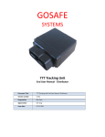
TABLE OF CONTENTS 1. Device Introduction 1.1 Device Introduction 1.2 Physical Appearance 1.3 Front view 1.4 Device Features 1.5 Scope of this file 1.6 Specification 1.7 Terms and Abbreviation 01 01 02 02 03 03 03 2. Quick Install Instructions 2.1 Remove sim socket cover 2.2 Insert SIM 2.3 Power on 2.4 Set User No 2.5 Modify Password 2.6 Set User Work Mode 2.7 Set Time Zone 2.8 Location poll 2.9 Set APN 2.10 Set TCP server Work Mode 04 04 05 06 07 08 09 11 00 00 3. Dual Communication 3.1 FM radio setting 3.2 Answer a call 3.3 Quick Dial a call 3.4 Step to dial a call 14 16 17 18 4.1 Power off alarm 4.2 Enable/Disable move alarm 4.3 Enable/Disable Over Speed Alarm and Set Parameter 4.4 Anti-jamming alarm 4.5 Enable/Disable Goe-fence Alarm 4.6 Clear alarm 19 19 19 20 20 20 4. Alarm 5. Power saving mode setting 5.1 GPS power save conditions 21 22 6. Other Functions 6.1 Adjusting Volume 6.2 Change ring tone and FM match music 6.3 Hotline number 6.4 Voice monitor 23 23 23 24 6.5 Query the phone conversation time 6.6 Wireless immobilizer 6.7 Combine Command 7. Structures of SMS from Device 7.1 Normal Location SMS (TXT format) 7.2 Normal Location SMS (Hyperlink Format ) 7.3 Error Command Alert 7.4 Alarm 8. LED Flashes & Relevant Device Status 9. Trouble shooting 9.1 Cannot receive reply SMS 9.2 GSM cannot online 9.3 Cannot start voice monitor 9.4 No ring from FM radio when calling 10. Appendix 10.1 User command list and default setting 24 24 25 26 26 26 27 28 29 29 30 30 31 1.DEVICE INTRODUCTION G717 is a simple tracking device which can be plugged into cigarette lighter port unlike anything else. Also it can fulfill dial‐communication with its inside microphone and using vehicle FM radio as speaker. Just by connecting to the cigarette lighter port, you can know within one minute the exact location of your G717. 1.2 PHYSICAL APPERANCE U SB SIM USB Configuration cable Wireless relay set (optional) 1 1.3 FRONT VIEW LED Calling Button Mini USB Reset Button SIM Socket MIC 1.4 DEVICE FEATURES Gets power from cigarette lighter port. Quick Dial Buttons that allow the device to call up to 3 pre‐determined numbers A sensitive microphone for using the cellular phone functions Using vehicle FM radio as speaker G‐force sensor to detect car accident 2.4G wireless immobilize relay to keep your car safety LED’s showing device status Quad‐band modem for worldwide coverage, with a highly sensitive GPS module Secure online account access for device personalization and tracking Use the Geo‐fence feature (also known as Safety Zone) to set defined perimeters around device and receive alert notifications 2 1.5 SCOPE OF THE FILE This file is only used for the user, who uses the mobile phone to fulfill the tracking. Other operations like server are not included in this document. 1.6 SPECIFICATION Physical Size Weight 108(L)x32(W)x32(H)mm 55g Environmental Temperature Humidity - 20 °C to + 60 °C 5‐75% Power Voltage Battery Power Consumption 9‐34V DC Li‐Ion 3.7V 180mAh 70mA(Active)500 uA(Sleep) GSM Antenna Modem Internal 500 uA Quad - Band 850/900/1800/1900MHZ GPS Antenna Receiver Channels Position Accuracy Sensitivity Internal uBlox NEO 6M 50 Parallel Channels Autonomous<2.5M -162dBm 1.7 TERMS AND ABBREVIATIONS Abbreviation APN MCC MNC GPRS GSM TCP UDP SMS IP LBS Description Access Point Network Mobile Country Code Mobile Network Code General Packet Radio Service Global System for Mobile Communications Transmission Control Protocol User Datagram Protocol Short Message Service Internet Protocol Location Based Service 3 2.QUICK INSTALL INSTRUCTIONS 2.1 REMOVE SIM SOCKET COVER 2.2 INSERT SIM CARD Insert SIM card into SIM socket.. Connect the device to cigarette lighter port. Wait until the blue LED always be ON (within 3 minutes). Note Before starting, please prepare the SIM card. SIM card should be network card with call number display, voice call. If you also want to use the TCP/UDP server, please open GPRS internet function of the SIM card. Please do activate the SIM card, disable its PIN code function, and make sure SIM card has enough balance. 4 2.3 POWER ON Connect the device to cigarette lighter port. Wait until the blue LED always be ON (within 3 minutes). 5 2.4 SET USER NO. To set user No., you can use any mobile phone to send the following SMS command to the SIM card No. which is inside the device: with country code Message 1234,UNO;+8613912345678 1234,UNO;13912345678 without country code Command Control Word Send SMS UNO:13912345678 Reply UNO:+8613912345678 Note “86” is country code of China. If the device is not used for international roaming, you can also ignore the country code and just send the phone number like “1234,UNO;13912345678”. Device will send SMS to user each 30 min or alarm triggered. To protect device, if there is any error in this command, device will not send back any error warning. Then user can fulfill other functions by sending user commands. After user sending command, device will reply one confirmation SMS back to user mobile phone. 6 2.5 MODIFY PASSWORD To modify user password at the first usage is strongly suggested. To modify password, you can use user No. Send following SMS command to the SIM card No.: New Password Message 1234,UPW;5678 Command Control Word Old Password Send SMS Reply UPW: 5678 Note Please memorize your New Password and wait for confirmation SMS for password modification from device. Only if this command is sent by user No. the system can process this command. 7 2.6 SET USER WORK MODE Device will send location information SMS or call to user by time set (default is 30 min). User can send following command to change the interval and data format. Data format of SMS Message 1234,UUM;30M;G;T Upload Mode Upload internal Command Control Word Password Send SMS Reply UUM: 30M;G;T Note: upload internal: “M” is the time unit. This unit can be “S”( second)/ “M” (min)/ “H(hour). ”30M” means upload interval is 30min. The range of this parameter is (30~900S)/(15~59M)/(1~240H). upload mode: “O”: close unloading. Then device will not send SMS to user by time set.“G”: upload GPS data by interval set. when there is no GPS , upload LBS (base station) data.“S”: upload LBS (base station) data by interval set with hexadecimal format.“L”: monitoring. Device call to user by interval set. Data format of SMS: “T”: text “W”: hyper‐link. In this format, device will send a web link. Example of close upload: 1234,UUM;30M;O;W Default :UUM0;30M;G;W 8 2.7 SET TIME ZONE After setting the time zone, device will send the local time in the SMS , provided that GPS data is valid. Also you can set the daylight saving time and device will automatically shift the time. If there is no GPS, data device will not send the time. 2.7.1 SET TIME ZONE COMMAND FORMAT Time Zone Message 1234,TZN;‐10:00 Command Control Word Password Send SMS Reply TZN:‐10:00 Note: “‐10:00” Time Zone. Enter the time zone parameter from ‐12:00 to 12:00. 9 2.7.2 SET DAYLIGHT SAVING TIME COMMAND FORMAT Message 1234, DST;03.27;10.01;00:00 1234, DST;03.F5;10.A0;00:00 DST:03.27;10.01;00:00 DST: 03.F5;10.A0;00:00 Start time End date Start date Command Control Word Password Send SMS Reply Note: “03.27”/” 03.F5”: Daylight saving time start date. You can use two formats. The first one is “month month. day day”. “03.27” represents March 27. The second one is ““month month. week day of week”. Week can be set “A B C D F”. "A" for the first week, "B" for the second week, and so on, the fifth week or last week can use the "F" to represent. Day of week can be set to “0 1 2……6”. Beginning on Sunday (“0” represent Sunday) to Saturday (“6” represent Saturday). ”03.F5” represents Friday on the last week of march. “10.01”/” 10.A0”: Daylight saving time start date. You can use two formats. Definition of format is same as parameter 3. “10.01” represents October 1st. “10.A0” represents Sunday on the first week of October “00.00”:start time, format is “hour hour: minute minute”.”00:00” represents time is “00:00” 10 2.8 LOCATION POLL There are two ways to poll the location from the device. 1) By sending PQR SMS to device: Command Control Word Message 1234,PRQ Password Send SMS Reply PRQ 2) User mobile can call to the device number and hang up after first ring. The device will send back the GPS location to the user mobile. 11 2.9 SET APN Only if the APN is set, you can goes to our web for tracking by using GPRS. Make sure your SIM card inside the device has turned on GPRS. APN Password Message 1234,APN;cmnet;internet;internet APN user name Access Point Name (Confirm Access Point Name from the service provider) Command Control Word Password Send SMS Reply APN:cmnet;internet;internet Note: If you only set the APN without the username and password “APN:cmnet, APN username: empty, APN password: empty”, command is: 1234,APN;cmnet Reply is: APN:cmnet;; 12 2.10 SET TCP SERVER WORK MODE Device will send location information to TCP server by time set (default is 60S). User can send following command to change the interval and data format. Data format of SMS Message 1234,TPM;30M;G;T Upload Mode Upload internal Command Control Word Password Send SMS Reply TPM:30M;G;T Note: upload internal: “M” is the time unit. This unit can be “S”( second)/ “M” (min)/ “H(hour). ”30M” means upload interval is 30min. The range of this parameter is (5~900S)/(15~59M)/(1~240H). upload mode: “O”: close unloading. Then device will not send SMS to user by time set.“G”: upload GPS data by interval set. when there is no GPS , upload LBS (base station) data.“S”: upload LBS (base station) data by interval set with hexadecimal format. Data format of SMS “T”: data format of SMS. Can set to: “T”: text “B”: binary Example of close upload: 1234,TPM;30M;O;W Default : TPM;60S;G;B 13 3 DUAL COMMUNICATION Note: This function is fulfilled by press “calling button”. There is a common definition for the button and buzzer. Please refer to “Trouble shooting‐ LED flashes and buzzer”. The maximum dial‐communication time is 3 minutes. 3.1 FM RADIO SETTING There is a microphone inside the device. And the speaker function is fulfilled by vehicle FM radio. Set a frequency parameter to device. Then when start Dual‐communication, device will send voice information to radio on the frequency set. The drawing bellow shows the structure for dial‐communication. FM Signal User mobile phone Device G717 (microphone inside) FM Radio (work as speaker) Use the following steps to set the FM radio. 14 3.1.1 SET FM RADIO MATCHING FREQUENCY User must avoid the frequency that is used by other companies. Set FM radio matching frequency parameter to device by using the following command. Sr. Description Ctrl Word Command 1 Set FM radio matching FMF frequency Reply 1234,FMF;8600 FMF: 8600 Remarks “8600”: Frequency. Parameter setting = real radio frequency /1000. If one want to use the frequency of 86MHz, then the, parameter should set to 8600 because parameter= 86,000,000/10000=8600. 3.1.2 MATCH BY BUTTON Here are steps for the matching. LED Hold on for 1~2 seconds Be -(last for 1 second) Red LED always on Hold on for 2~5 seconds Be -, Be- each last for 1 second Red LED flash frequency is 1 second Operation wait status Red LED flash frequency is 1 second Adjust FM radio to the matching frequency A song rings when Match successfully Red LED flash frequency is 1 second Matching Step 5 Release “calling button” Status Step 6 Step 4 Step 1 Step 2 Buzzer/sound Be (Buzzer on stimultaneously for button press) Step 3 Operation Press “calling button” Press “calling button” to exist No song Blue LED always on Standby status 15 3.2 ANSWER A CALL Following are the steps to answer a call: LED Status Phone calling in Pickup phone (turn on FM radio and set to matching frequency. Press “calling button for less then 1 second) Blue LED fresh frequencyis 1 second Dual Communication Device stop dual communication (press “calling button for less then 1 second) Blue LED always on Exist Dual Communication (goes to standby status Blue LED always on Exist Dual Communication (goes to standby status Blue LED always on Standby status Step 5 Step 4 Red LED and blue LED flash alternatively Step 2 Phone calling in Buzzer/sound Step 3 Step 1 Operation Pickup phone Hang up phone Calling phone stop dualcommuncation Hang up phone (press “calling button for more then 2 seconds) Be-, Be Be & Song rings Be Be Be 16 3.3 QUICK DIAL A CALL You can save 3 quick dial phone numbers in the device by using the following command: Message 1234,FCL0;13862563211 1234,FCL1;+8613845673456 Command Control Word Password Send SMS FCL0:13862563211 FCL1:+8613845673456 Reply Note “FCL0” is used for phone number 1 “FCL1” is for number 2 and “FCL2” is used for number 3. “13862563211”/”+8613845673456”: phone number. If device or phone number may be in roaming function, please add “+country code” in front of the number like Exp. ”+8613845673456”. 17 3.4 STEP TO DIAL A CALL Following are the steps to dial a call; Step 1 Hold on for 1~2 second Be-(last for 1 second) release “calling button” Pick up Device stop dual-communication (press “calling button for less then 1 second”) Step 7 Step 5 Dial to first number: Press one time within 1 second Dial to second number: Press 2 times within 1.5 second Dial to third number: Press 3 times within 2 second (please dial out within 5S after button released. otherwise device exist will to standby status) Step 6 Step 4 Turn on FM radio and set to the matching frequency. Press “calling button” Step 2 Buzzer/sound Be (buzzer on simultaneously for button press) Step 3 Operation phone stop dual-communication or phone number does not exist buzzer on simultaneously for each button press Be Be Be LED Status red LED always on operation wait status red LED always on operation status Red LED and blue Calling out LED flash alternatively Blue LED fresh frequency is 1 second Dual-communication Blue LED always ON Exist dualcommunication (goes to Standby status) Blue LED always ON Exist dualcommunication (goes to Standby status) 18 4. ALARM When alarm triggered, device will send one SMS to user mobile phone with the location information. In default setting, device will send alarm twice and interval is 3 min. Then it will automatically clear alarm and send alarm again when new alarm will be triggered. You can use OEM software to set upload times and interval and clear alarm by receiving command (setting method is not mentioned in this document). Here is a sample of moving alarm when GPS location is valid. Device send alarm: http://maps.google.com/maps?q=23.164472,113.428360&t=m&z=16 Alarm: Moving COMMANDS FOR ALARMS Sr. Description Ctrl Word Command Reply Remarks 4.1 Power off alarm When device is disconnected with the external power, this alarm will be triggered. 4.2 Enable/Disable move alarm MOT MOT;0 MOT;1 MOT:0 MOT:1 There is a movement sensor inside the device. When device status shift from stop to moving, it will send move alarm. You can enable / disable this alarm by disable the movement sensor. “1”/“0”: enable/disable movement sensor. can set to “0”(disable)/ “1”(enable”). When disable the movement sensor, device status will always be stopped (No movement status) 4.3 Enable/Disable Over Speed Alarm SPO and Set Parameter SPO;0 SPO;1 SPO:0 SPO:1 “0”/”1”: enable/disable alarm. Can set to “0”(disable)/ “1”(enable”). Default is disable over‐speed alarm. SOP; 100;120 “120”: alarm speed. unit: KM/H. in this sample, “120” means alarm speed is 120KM/H. SOP: 100;120 Default is “1234, SOP;80;100” which means alarm speed threshold is 100KM/H. Set the alert and SOP alarm speed 19 Sr. Description Ctrl Word Command Reply Remarks Our device can test whether there is a jamming and send alarm to user after jamming is cleared . Then user can get the information that somebody is trying to steal the device or doing something bad. 4.4 Anti‐jamming alarm 4.5 Enable/Disable Goe‐fence Alarm GOF GOF;0 GOF;87 GOF:0 GOF:87 There are 28 fences in total, from numbers 0 to 27. You can enable/disable alarm for different fence independently by sending the following command. “0”/”87”: enable/disable alarm for different geo‐fence. Range:0~ FFFFFFF hexadecimal format. Each bit of this parameter represents one geo‐fence. Bit0 represent geo‐fence0 and bit1 represent geo‐fence 1.….. definition of each bit is: “0”:disable geo‐fence “1”:enable geo‐fence In this sample, user want to “enable alarm for fence 0&1&2&7”, which means bit0&bit1&bit2&bit7 are set to “1” (enable) and the other bits are set to “0”(disable). Shown in binary format is “0000 0000 0000 0000 0000 1000 0111” which equals to “0000087” in hexadecimal. The front data of “00000” can be ignored. Then the parameter 3 is set to “87”. Default :GOF;FFFFFFF (means enable all the goe‐fence) 4.6 Clear alarm UAC UAC In default, device will clear alarm after it sends twice for one alarm triggered. UAC 20 5. POWER SAVING MODE SETTING In order to save the power, device can power off GPS and GSM modem separately when device is standby. Working process: When the upload time set is up or an alarm is triggered, modems will wake up. The maximum wake up time is 6 minutes. If there is GSM signal, device uploads data. If there is no GSM signal, device will save the data in flash. When upload works are finished, device will power off the modems again. User can enable power save function by the following command. Message GSM power save function 1234,PSM;1;0 GPS power save function Command Control Word Password Send SMS PSM:1;0 Reply Note “1”(enable) and “0”(disable). Only if the upload intervals for user and server are larger then 15 min, power save function can be used. 21 5.1 GPS POWER SAVE CONDITIONS Because some functions are related to GPS location data, in order to fulfill GPS power save function, you need to close the following functions: Close mileage upload function (OEM configuration software or web setting using MGE command. default is open) Close geo‐fence alarm function (user can set, please refer to part “4 Alarm”. Default is open ) Close over‐speed alarm function (user can set, please refer to part “4 Alarm”. Default is close) Close upload data when harsh turn occurred (OEM configurationsoftware or web setting using TRN command. Default is close). Close function of “upload data by distance”. (OEM configuration software or web setting using DIS command. Default is close). Close upload data when speed changed occurred (OEM configuration software or web setting using SPD command. Default is close). 22 6. OTHER FUNCTIONS COMMAND TABLE Sr. Description Ctrl Word Command 6.1 Adjusting Volume AGN 6.2 Change ring tone and FM match music TON 6.3 Hotline number HOT Reply Remarks AGN;9;10 AGN:9;10 Please do not adjust the volume if there is no issue because some noise may be occurred. “9”: microphone volume. Set this parameter to change the volume of the microphone. The lager number represents larger voice volume. Range: 0~18. “90”: speaker volume. Set this parameter to change the volume of the speaker. The lager number represents larger voice volume. range: 0~16 default: AGN; 18;4 TON;1;6 TON:1;6 When a phone is calling to device, device rings. When FM radio frequency matched during the setting process, device has a music come up. Use can change the ring tone and music by the command. “1”: One number relate to one kind of ring tone.Range:0~8 “6”:FM match music. One number relate to one kind of music.range: 0~18 Default: TON;1;6 When hotline number calls to device, device will pick up automatically. This can forced the device to start dual‐communication. You can set 15 hotline numbers and user number can be one of them. Please use OEM configuration or our web to set the numbers. When SOS alarm triggered, device will also send alarm to hotline HOT0; +8613912 HOT0:+8613912 numbers. Hotline number can also clear the SOS alarm by calling to device. User number 323456 323456 can also fulfill this function by the following or or command. HOT0; 13912323 HOT0:13912323 “+8613912345678”: Call back number. “+” is 456 456 country code mark while “86” is country code of China. If the device is not going to dial to international phone, you can also ignore the country code and just send command like “1234,CAL;13912345678”. After device received this command, it will dial back to the number and start dual‐communication. 23 Sr. Description Ctrl Word Command 6.4 Voice monitor VOM Reply Remarks This function is used to start the voice monitor without knowing by the device holder or when device holder is in dangerous, it is batter to start voice monitor. There are two methods. “+8613912345678”: Call back number. “+” is VOM; +86139123 VOM: +8613912 country code mark while “86” is country code of China. If the device is not going to dial to 45678 345678 international phone, you can also ignore the country code and just send command like “1234,VOM;13912345678”. After device received this command, it will dial back to the number of “para3” and only open microphone (do not open speaker). Then user starts to monitor. set voice monitor number When voice monitor number calls to device, device will pick up automatically and only open microphone (do not open speaker). You can set 5 numbers. The voice monitor numbers you set cannot use dual‐communication function because when these numbers call to device, device will pick up quickly and start monitor function. Please use OEM configuration or our web to set the numbers. 6.5 Query the phone conversation time “50”: total incoming call time. unit is seconds. This time will reset to “0” after it is up to 2 32 seconds. Reply, “180”: total incoming call time. Total outgoing call time. unit is seconds. This time will reset to “0” after it is up to 232 seconds. CTR CTR CTR:50;180 6.6 Wireless immobilizer Only if you have the wireless relay, this function can be fulfilled.Please <install manual GSI‐470> to install the immobilize relay on your vehicle. 1)control the IMM immobilizer output IMM;1 IMM:1 “1”: Immobilizer output control. This parameter can be: "0" : immobilize output OFF "1”: immobilize output ON 2)to check immobilizer connected. RFS RFS:1 “1”: indicate whether there is immobilizer connected. This parameter can be: “0”(disconnect) or “1” (connected) RFS 24 6.7 COMBINED COMMANDS To save time and SMS resource on configuration, user can apply combine command, in which there is more than one command, to operate configuration. The combine command would begin with user password, which is followed by commands (commands order is flexible). Pw , Command word ; Parameter First command ; Parameter , Command word ; Parameter Second Command If there is duplication of the same command in the same combine command, just the last piece of command would be processed; if there is error in the command, the command with error would be discarded, and device would only confirm setting of correct commands with no error warning. If all the commands are error, an alarm will be sent. All setting commands, except user No. setting command under the condition of the user number has never been changed, can be set by combine command. Example:1234,UUM;30M;G;T,UPW;1234 25 7. STRUCTURES OF SMS FROM DEVICE 7.1NORMAL LOCATION SMS (TXT FORMAT) (Located Successful) G717 V1.38 GPS 8/3 UTC 12‐06‐26 12:24:20 N23.164536 E113.428459 SPD:10km/h 5 TMP=35.6C PWR=12.2V Device Name and Version Satellites Connected &Time used for Location (secs) Greenwich date and time(if time zoon is set, start head is “LTM”) Latitude in degree‐minute format Longitude in degree‐minute format Device speed and Move Direction Temperature Power (Located Unsuccessful) use LBS G717 V1.38 UTC 12‐06‐26 12:24:20 MCC=460 MNC=1 LAC=2503 CID=962C TMP=35.6C PWR=12.2V Device Name and Version Greenwich date and time(if time zoon is set, start head is “LTM”) Mobile Country Code Mobile Network Code Location Area Code Cell Identity Temperature Power 7.2 NORMAL LOCATION SMS (HYPERLINK FORMAT) (Located Successful)Google link G717 V1.38 http://maps.google.com/maps?q=23.164375,113.4284 21&t=m&z=16 TMP=35.1C PWR=12.2V Device Name and Version Google Map Link Temperature Power (Located Unsuccessful) use LBS G717 V1.38 UTC 12‐06‐26 02:24:20 MCC=460 MNC=1 LAC=2503 CID=962C TMP=30.6C PWR=12.2V Device Name and Version Greenwich date and time(if time zoon is set, start head is “LTM”) Mobile Country Code Mobile Network Code Location Area Code Cell Identity Temperature Power 7.3 ERROR COMMAND ALERT Gosafe G717 V1.38 Error command! 26 7.4 ALARM Alarm type SMS received (hyperlink) SMS received (TXT) SMS received (LBS) Power off G717 V1.38 http://maps.google.com/map s?q=23.164472,113.428360&t =m&z=16 Alarm: Power Off G717 V1.38 GPS 8/3 UTC 12‐06‐26 11:44:20 N23.164472 E113.428672 SPD:1km/h 0 Alarm: Power Off G717 V1.38 UTC 12‐06‐26 01:47:08 MCC=460 MNC=0 LAC=2503 CID=962C Alarm: Power Off move G717 V1.38 http://maps.google.com/map s?q=23.164472,113.428360&t =m&z=16 Alarm: Moving G717 V1.38 GPS 8/3 UTC 12‐06‐26 11:44:20 N23.164472 E113.428672 SPD:1km/h 0 Alarm: Moving G717 V1.38 UTC 12‐06‐26 01:47:08 MCC=460 MNC=0 LAC=2503 CID=962C Alarm: Moving over‐speed G717 V1.38 http://maps.google.com/map s?q=23.164472,113.428360&t =m&z=16 Alarm: Over Speed G717 V1.38 GPS 9/3 UTC 12‐06‐08 12:24:20 N23.164614 E113.428672 SPD:100km/h 8 Alarm: Over Speed G717 V1.38 UTC 12‐06‐26 01:47:08 MCC=460 MNC=0 LAC=2503 CID=962C Alarm: Over Speed anti‐jamming G717 V1.38 http://maps.google.com/map s?q=23.164472,113.428360&t =m&z=16 Alarm: Anti‐Jamming G717 V1.38 GPS 9/3 UTC 12‐06‐08 12:24:20 N23.164614 E113.428672 SPD:10km/h 5 Alarm: Anti‐Jamming G717 V1.38 UTC 12‐06‐26 01:47:08 MCC=460 MNC=0 LAC=2503 CID=962C Alarm: Anti‐Jamming geo‐fence G717 V1.38 http://maps.google.com/map s?q=23.164472,113.428360&t =m&z=16 Alarm: Geo‐Fence in G717 V1.38 GPS 9/3 UTC 12‐06‐08 12:24:20 N23.164614 E113.428672 SPD:10km/h 5 Alarm: Geo‐Fence in G717 V1.38 MCC=460 MNC=0 LAC=2503 CID=962C Alarm: Geo‐Fence in 27 8. LED FLASHES & RELEVANT DEVICE STATUS There is an external LED light to reflect device status in G717. When device is working correctly and can go online, device LED indication is shown as follow: Status LED Flashes Standby status Blue LED always being on (low luminance) Operation wait status Red LED always being on (low luminance) Calling in or out Blue and red LED fresh alternatively. Frequency is 1 second During dual‐communication Blue LED fresh, Frequency is 1 second Matching successfully Red LED fresh, Frequency is 1 second Device also uses red LED flashes to indicate relevant error if any of the following situations happens: Device Error, SIM card no balance, GSM network cannot register. User can count LED quick flashes then compare it to below table: Error Details LED Flashes Solutions GSM module Communication Error 1 flash Power OFF then check GSMmodule power supply and communication SIM card Error 2 flash Power OFF then check whether SIM installation is good and PIN is disabled Cannot register at GSM network 3 flash To check whether SIM card is overdue and/or device in an area there is no GSM signal GPS module Error 4 flash Power OFF then check GPS module power supply and communication SMS Sending Error 5 flash To check whether there is SIM card SMS center setting error and/or SIM card is overdue Can’t use GPRS 6 flash To check whether the APN is correct and SIM has GPRS function or not TCP connection Error 7 flash To check if the server is normal Unknown Error 8 flash Power OFF then Power ON, if there is still the error, please contacts us. 28 9. TROUBLE SHOOTING Sr. Description Ctrl Word Command 9.1 Cannot receive SCN reply SMS Reply Remarks when device power is on, it will search the SMS center number cannot search by device. Solution: send command to change the SMS center number. Make sure that the number is SCN;+861380013 SCN:+86138001 correct. 8000 38000 “+” is country code mark while “86” is country code of China. This number must have country code. 9.2 GSM cannot online 1) Check GSM REG register 2) Check the signal quality CSQ 3) Check TCP TPS connect REG CSQ TPS REG:1 “1”: indicate weather GSM can register. This parameter can be: “0”: no registered. Mobile Equipment is not searching new telecom provider. “1”: registered local telecom provider “2”: not registered. Mobile Equipment is searching new telecom provider. “3”: register rejected “4”: not registered. Unknown reason. “5”: registered roaming. If reply is “0” or “2” or “3”, please contact the tech support engineer. CSQ:1 para‐“1”: indicate the GPS signal quality. This parameter can be: "0": no signal "1": weak signal "2": not good signal "3"/"4": good signal "5": best signal Please contact to tech engineer if reply parameter is “0”. TPS:1 “1”: indicate weather TCP can connect. This parameter can be: "0": no connection "1": connect to fixed IP "2": connect to domain Please contact to tech engineer if reply parameter is “0”. 29 Sr. Description Ctrl Word Command Reply 9.3 Cannot start voice monitor 9.4 No ring from FM radio when FMS calling Remarks SIM card inside device do not have call number display function. Then device will not pickup automatically because it does not recognize the number. Please open this function. 1) Please confirm that the FM radio setting is correct and matched to device. If during matching process, there is a song comes up. FMS FMS:ERROR 2) If setting is correct, please send the command “ERROR”: if parameter is “ERROR”, please contact support engineer. If reply digit number, need to check other problems. 30 10. USER COMMAND LIST AND DEFAULT SETTING ID Command Explain Default DFP command Upgrade firmware parameters reset to default reset to default Set user phone number empty √ × words 1 UNO 2 UPW Set user password UPW;1234 √ × 3 UUM User upload mode UUM0;30M;G;W UUM1;12H;G;W √ × 4 UAC User alarm clear none × × PRQ Request location information none × × 6 SCN SMS center number empty × × 7 APN APN none × √ 8 CAL Dual communication none × × 9 VOM Voice monitor none × × 10 SPO enable/disable over Speed SPO;0 √ × 11 SOP Speeding alarm parameters setting SOP;80;100 √ × 12 MOT Enable/ disable movement sensor MOT;1 √ × 13 GOF Enable /disable Geo‐fence GOF;FFFFFFF √ × 14 TZN Time zone setting TZN;0:00 √ × 15 IMM Immobilize output IMM;0 √ × 16 FCL Quick call list empty × √ DST Daylight‐saving time setting DST;0 √ × 8600 √ × empty × × empty × × 5 17 18 FMF 19 CTR 20 CSQ FM frequency setting Query the phone conversation time Query GSM signal quality 31 ID Command Explain words Default DFP command Upgrade firmware parameters reset to default reset to default 13 RFS Query wireless 2.4G status 12 ERS Query error status empty 14 FMS Query FM status empty × × × × 15 AGN Audio volume setting AGN;8;4 √ × 16 TON Ringing tone setting/ FM match music TON;1;6 √ × 15 REG Query GSM register status empty × × 16 TPS Query TCP connection status empty × × empty × × 32 www.gosafesystem.com