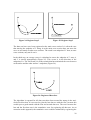
1
REHAB Tech- Monash Rehabilitation Technology Research Unit assume no liability for any claim of adverse effects resulting from misapplication of the information presented here in. While every effort is made to ensure the accuracy of the guide no responsibility or liability will be taken for any inaccuracies. REHABTech is finance and supported by In collaboration with © Copyright 1998 All rights reserved. No part of this publication may be reproduced or transmitted in any form or by any means, electronic or mechanical, including photocopy, recording or any information storage and retrieval system, without permission in writing from the publisher. Requests for permission to make copies of any part of the work should be addressed to: REHAB Tech- Monash Rehabilitation Technology Research Unit C/- C.G.M.C. 260 - 294 Kooyong Road CAULFIELD VIC 3162 AUSTRALIA Email [email protected] A SYSTEM FOR NON-CONTACT MEASUREMENT OF AMPUTEE STUMPS. 1995 Bearsley A, Brown T I H, Ng K-Centre for Biomedical Engineering Andrew Beasley- Biomedical Engineering (Monash University) undertook a study involving the programming and application of three dimensional imaging to lower limb anatomical features in particular a trans-tibial stump. A system known as Computer Aided Non-contact Volumetric Analysisof Stumps (referred to as CANVAS) was designed to measure accurately the shape and volume of a below-knee stump. The CANVAS System was designed to be used in a clinical environment, allowing precise quantification of volumetric changes that are occurring in the residual limb. CANVAS uses the Monash 3-D Shape Measurement System for acquiring stump surface data. The measurement system consists of a Charge Coupled Device camera and a light projector with a liquid crystal filter. The Shape Measurement System projects a series of stripes onto the stump, then uses triangulation to calculate a set of discrete points on the stump surface. At least 5 measurements from around the stump are required to cover the full 360 degree surface. CANVAS processes the data sets, merging them into a cylindrical model representing the surface. Multiple surfaces were superimposed and presented graphically, allowing visual comparison. The prototype CANVAS System was tested on a plaster case of a below-knee stump, simulating volumetric changes with plasticine.These localised volumetric changes could be clearly quantified. Abstract The CANVAS System was designed to enable volumetric measurement of belowknee stumps in a clinical environment. It allows prosthetists to observe volumetric changes that are occurring in the residual limb, so they are better informed to decide when repacking or replacement of the prosthesis socket is necessary. CANVAS uses the Monash 3-D Shape Measurement System for acquiring stump surface data. The measurement system has a fast imaging time and is capable of precise non-contact surface measurements. The data sets acquired from a plaster cast of a below-knee stump were processed by CANVAS and merged into a cylindrical model representing the surface. Multiple surfaces were presented graphically allowing visual comparison. Localised volumetric changes could be clearly identified. Before the CANVAS System is ready for clinical operation, the method of data set registration needs improvement, stump registration must be implemented and a physical set up should be constructed and tested. Table of Contents 1. Abstract ......................................................................................................................3 2. Table of Contents .......................................................................................................4 3. Table of Figures..........................................................................................................6 4. Stake Holders .............................................................................................................8 5. Background ................................................................................................................9 5.1 Possible Reasons for Amputation.........................................................................9 5.2 Method of Below-Knee Amputation ....................................................................9 5.3 Why the Prosthetist is Interested in Volume Changes........................................10 5.4 Prosthetic CAD/CAM Systems ..........................................................................11 5.5 The Monash 3-D Shape Measurement System...................................................13 5.6 Advantages of the 3-D Shape Measurement System..........................................15 6. The CANVAS System..............................................................................................16 6.1 An Overview.......................................................................................................16 6.2 The CANVAS Environment...............................................................................17 6.3 Calibration of the 3-D Shape Measurement System...........................................18 6.4 Acquisition of Stump Data Sets .........................................................................19 6.4.1 The 3-D Shape Data Set...............................................................................19 6.4.2 Capturing a Full 360 Degree Surface...........................................................19 6.4.3 Calculating the Centre of Rotation ..............................................................20 6.5 Loading Data Sets into CANVAS ......................................................................23 6.5.1 Loading Calibration Files.............................................................................23 6.5.2 Loading Shape Data Files ............................................................................23 6.5.3 Calculation of Missing Points......................................................................24 6.5.4 Clipping the Data Set ...................................................................................25 6.5.5 Filtering Outlier Points ................................................................................25 6.6 Choice of Coordinate System .............................................................................27 6.7 Sampling Data Sets.............................................................................................29 6.7.1 Properties of Cardinal Spline Patches..........................................................29 6.7.2 Intersecting a Cardinal Patch with a Grid Line............................................31 6.7.3 The CANVAS Subdivision Algorithm ........................................................31 6.7.4 CANVAS Subdivision: Operation Details...................................................33 6.7.5 CANVAS Subdivision: Screen Output........................................................34 6.8 Registration of Data Sets ....................................................................................35 6.8.1 The Reason for Position Error .....................................................................35 6.8.2 The CANVAS Registration Algorithm........................................................36 6.8.3 CANVAS Registration: Screen Output .......................................................38 6.8.4 Linking Data Sets.........................................................................................40 6.9 Presentation of Data............................................................................................41 6.9.1 3-D Wireframe View ...................................................................................41 6.9.2 Cross Section View......................................................................................42 6.9.3 Cross Section Area Chart.............................................................................43 2 7. Results ......................................................................................................................45 7.1 Method of Testing CANVAS System ................................................................45 7.2 Calculating the Centre of Rotation .....................................................................45 7.3 Loading and Sampling Data Sets........................................................................46 7.4 Registration of Data Sets ....................................................................................47 7.5 Data Set Coverage of Surface.............................................................................48 7.6 Comparison of Stump Surfaces ..........................................................................49 7.7 System Accuracy ................................................................................................49 8. Other Issues ..............................................................................................................51 8.1 Registration of Stump Surfaces ..........................................................................51 8.1.1 Landmark Registration.................................................................................51 8.1.2 Centroid Registration ...................................................................................52 8.1.3 Manual Software Registration .....................................................................52 8.1.4 Manual Physical Registration ......................................................................52 8.2 Physical Set Up of Equipment............................................................................53 8.2.1 Measurement System Configuration............................................................53 8.2.2 Patient Support.............................................................................................55 9. Future Work .............................................................................................................56 10. Conclusion..............................................................................................................57 11. Acknowledgments..................................................................................................59 12. References ..............................................................................................................60 13. Appendix A ............................................................................................................62 3 Table of Figures FIGURE 1: MONASH 3-D SHAPE MEASUREMENT SYSTEM 13 FIGURE 2: CALIBRATION FRAME WITH TARGET POINTS 14 FIGURE 3: ORIGINAL PLASTER CAST OF STUMP USED AS MODEL FOR CANVAS 17 FIGURE 4: MODIFIED PLASTER CAST USED TO SIMULATE VOLUMETRIC CHANGE 17 FIGURE 5: TOP VIEW OF CALIBRATION FRAME ON TURNTABLE 20 FIGURE 6: STEP 1. CALCULATE THE INTERSECTION BETWEEN PRINCIPAL AXES 1, 2 22 FIGURE 7: STEP 2,3. CALCULATE LINES A, B WHICH PASS THROUGH I 12 22 FIGURE 8: STEP 4. REPEAT THE PROCESS FOR PRINCIPAL AXES 2, 3 22 FIGURE 9: STEP 5. CALCULATE COR, THE INTERSECTION BETWEEN LINES B 1 AND B2 22 FIGURE 10: WEIGHTED AVERAGE 24 FIGURE 11: INTERSECTING SPLINES 24 FIGURE 12: CANVAS WITH LOADED DATA SET 25 FIGURE 13: CANVAS WITH 6 LOADED DATA SETS 26 FIGURE 14: CYLINDRICAL COORDINATE SYSTEM 28 FIGURE 15: CARDINAL PATCH WITH CONTROL POINTS 30 FIGURE 16: FLOW CHART OF CANVAS SUBDIVISION ALGORITHM 32 FIGURE 17: SURFACE PATCH 33 FIGURE 18: PROGRESS AFTER 5 ITERATIONS 33 FIGURE 19: DATA SET SAMPLED WITH CARDINAL PATCHES 34 FIGURE 20: CENTRE AT ORIGIN 35 FIGURE 21: CENTRE NOT AT ORIGIN 35 FIGURE 22: UNREGISTERED DATA SETS 36 FIGURE 23: REGISTRATION STEP 1 36 FIGURE 24: REGISTER STEP 2 37 FIGURE 25: REGISTER STEP 3 37 FIGURE 26: REGISTERED DATA SETS 37 FIGURE 27: CROSS SECTION OF DATA SETS BEFORE REGISTRATION 38 FIGURE 28: CROSS SECTION OF DATA SETS AFTER REGISTRATION 39 FIGURE 29: MULTI CROSS SECTION OF DATA SETS AFTER REGISTRATION 39 FIGURE 30: 3-D WIREFRAME VIEW OF STUMP DATA 41 FIGURE 31: 3-D VIEW CONTROL 42 FIGURE 32: CROSS SECTION VIEW OF STUMP DATA 43 FIGURE 33: TOTAL CROSS SECTION AREA VERSUS Z-AXIS 44 FIGURE 34: CROSS SECTION AREA FOR SPECIFIC SECTOR VERSUS Z-AXIS 44 FIGURE 35: SQUARE AND DIAMOND SHAPED NEIGHBOURHOODS CARDINAL PATCHES 46 FIGURE 36: HYPOTHETICAL GRAPH OF REGISTRATION ERROR VS. POSITION ON Z-AXIS 47 FIGURE 37: POSSIBLE CONFIGURATION OF MEASUREMENT SYSTEM USING MIRRORS 54 FIGURE 38: POSSIBLE STRUCTURE TO SUPPORT PATIENT FOR STUMP MEASUREMENT 55 FIGURE 39: CANVAS SCREEN: SAMPLED DATA SET (000 DEGREES) 62 FIGURE 40 CANVAS SCREEN: SAMPLED DATA SET (072 DEGREES) 62 FIGURE 41: CANVAS SCREEN: SAMPLED DATA SET (144 DEGREES) 63 4 FIGURE 42: CANVAS SCREEN: SAMPLED DATA SET (216 DEGREES) 63 FIGURE 43: CANVAS SCREEN: SAMPLED DATA SET (288 DEGREES) 64 FIGURE 44: CANVAS SCREEN: 3-D WIREFRAME MODE 64 FIGURE 45: CANVAS SCREEN: MERGED DUAL CROSS SECTION 65 FIGURE 46: CANVAS SCREEN: MERGED DUAL CROSS SECTION SHOWING SMALL VOLUMETRIC CHANGE 65 FIGURE 47: CANVAS SCREEN: CHART OF TOTAL CROSS SECTION AREA VS. Z-AXIS 66 FIGURE 48: CANVAS SCREEN: CHART OF SECTOR AREA VS. Z-AXIS 66 5 Stake Holders A number of people were consulted in relation to this project. Associate Professor Ian Brown of the Computer Systems and Electrical Engineering Department, Monash University supervised the project, and was consulted in relation to the theoretical and practical aspects of prosthetic imaging. Associate Professor Kim Ng of the Computer Systems and Electrical Engineering Department, Monash University co-supervised the project, providing technical expertise with the Monash 3D Shape Measurement System. Dr Andrew Nunn, Director of the Amputee Unit of the Caulfield Medical Centre and Mr Bill Contoyannis of the Caulfield Medical Centre were consulted throughout in relation to clinical aspects of this project. 6 Background 5.1 Possible Reasons for Amputation As a rough estimate, one in every thousand Australians will have an amputation at some stage of their lives. Of these, 60 to 80 percent will have below-knee amputations. Personal communication with Dr Andrew Nunn and Bill Contoyannis of the Caulfield Medical Centre (21/1/94) has indicated that around 10 percent of below-knee amputations are associated with trauma, such as motor accidents. Most of the remaining 90 percent of amputations are related to blood circulation problems. The two main causes for poor circulation are peripheral vascular disease and diabetes. Restricted circulation means that blood has difficulty flowing through the extremities and infection may occur. In the case of a non-viable, non-functional or painful foot, a common place to amputate is below the knee. At this point there are large enough arteries to encourage blood flow through the remaining stump, or residual limb. 5.2 Method of Below-Knee Amputation Trans-tibial (below-knee) amputation involves cutting through the bones that run down the lower leg, namely the tibia and fibula. These bones are bevelled off to remove any sharp corners that may cut through tissue. There are a variety of techniques that involve wrapping a bulk of muscle with good blood circulation (known as a muscle flap) over the bottom of the tibia. The muscles are stitched back onto the tibia and to other muscles. The initially bulbous stump will naturally shrink after the initial swelling resolves until it settles to a constant volume. The circulation of fluid and compression of soft tissues eventually becomes stable. Below-knee ligaments and muscles may also shrink as they are no longer used to their original capacity. The end result 6 to 12 months later is dramatically different from the volume and shape of the immediate postoperation stump. 5.3 Why the Prosthetist is Interested in Volume Changes Within a few weeks after the operation, the patient is fitted with a custom made interim limb as a temporary measure by the prosthetist. This artificial limb 7 (prosthesis) connects to the patient through a socket that applies pressure to the stump. This applied pressure from the socket accelerates the natural shrinkage of the residual limb. If the pressure can be maintained, the stump will stabilise more rapidly and the patient can spend less time in hospital. As the stump shrinks, the temporary socket becomes a loose fit and cannot apply the correct pressure. The aim is total contact between the stump and socket, but pressure tolerant structures are be loaded and vulnerable areas relieved. The prosthetist must alter the socket over the shrinking process so that it stays a comfortable fit, with pressure maintained on the stump. For this reason, it is important that the prosthetist has an understanding of the volumetric changes within the limb. An active knowledge of the changes taking place means that the prosthetist is better informed to decide when and where repacking or replacement of the temporary socket is necessary. If the shape of the stump has stabilised, then the prosthetist can fabricate a definitive (final) prosthesis, which is sturdy and will last for years. If the prosthetist thinks that the stump has almost stabilised, he or she will reduce the frequency of the packing. This in turn means that the shrinking slows. If the prosthetist is mistaken and issues the definitive prosthesis, then it is likely that the fit will become loose and uncomfortable. The patient will need to return to hospital later for another ‘final’ prosthetic limb. The current method of change-estimation is by guessing, and is prone to error. It can be very difficult for the prosthetist to know if the stump has gone from one volume to another unless the changes are visually obvious. The stump can be compared with a plaster cast taken previously, but the comparison of shape is unreliable due to the inaccuracies of the casting technique. It would be useful, therefore, to have a method for quantification of volume and shape changes in a stump over time. A rough approach would be to use Archimedes’ principle, by placing the stump in a body of water and measuring the volume displaced. This would show a net change in volume, but would not illustrate subtle, local changes that are important to the prosthetist. A more accurate approach, showing local shape change would involve detailed measurement and comparison of the stump shape over time. 5.4 Prosthetic CAD/CAM Systems Shape sensing technology for the field of prosthetics and orthotics was introduced in the 1980s, and has become more commercially viable as the capability of computing technology increases, and the cost of hardware decreases. 8 Prosthetic CAD/CAM1 systems have the ability to capture and manipulate stump images, using various forms of technology such as laser contours or touch sensing by mechanical pin. When looking at below-knee stumps, the application of this technology has been focussed on the computer aided manufacture of prosthetic sockets. Carl Saunders, James Foort and others began to explore the possibilities of CAD/CAM for prosthetic design in the mid 1970s. By the mid 1980s, Saunders et al. (1985) had produced a prototype Computer Aided Socket Design (CASD) system for the design and manufacture of trans-tibial (below-knee) sockets. Measurements of the stump were taken manually with callipers at intervals of 1 inch, and a basic conical socket shape was scaled appropriately. A system with a similar purpose, described by Fernie (1984), acquired data through a rotating setup of 9 cameras. A straight line of light was projected onto the stump surface, and the resultant (distorted) line on the stump was captured on camera and interpreted electronically. The measurement by camera took less than a second. A major disadvantage of these two approaches was the parametric model used to represent the shape, involving the scaling of a stump template. Later clinical tests, documented by Konig (1987), Holden and Fernie (1986), showed that this model was difficult to apply to patients with stumps in a general shape other than conical (eg. bulbous or cylindrical). The parametric approach could not model more subtle, local changes of shape to a sufficient accuracy. A non-parametric approach was by taken by the Swedish CAPOD2 system, with some success documented by Öberg et al., (1993). CAPOD used a laser digitiser to obtain a topographical contour of the stump, which was modelled as a set of digital coordinates rather than scaling a template from a database of possible stump shapes. The Bioengineering Centre at the University College of London developed a mechanical system that used a probe in direct contact with a plaster wrap of a stump, as mentioned by Köhler et al., (1989), and described in more detail by Travis and Dewer (1993). The probe was used to trace a helical path inside the wrap, and its displacement encoded to produce a 3-dimensional representation of the surface in cylindrical coordinates. The trend in recent developments in prosthetic imaging is towards systems utilising non-contact shape measurement techniques to capture the surface topography. These systems typically require a scanning device such as a low-powered laser to be rotated around the stump, taking stripe measurements at intervals of less than 5 degrees. 1 2 CAD/CAM: Computer Aided Design / Computer Aided Manufacture CAPOD: Computer Aided Prosthetic and Orthotic Design 9 Some advantages of optical/laser imaging as compared with ultrasound or mechanical digitisation are an increased accuracy of measurement, without the need for a plaster cast. The laser scanner used by Engsberg et al. (1992) achieved an error of less than + 1.5 mm, which was deemed accurate enough for the application. 5.5 The Monash 3-D Shape Measurement System The Monash 3-D Shape Measurement System was developed in the Department of Electrical and Computer Systems Engineering at Monash University, under the direction of Associate Professor Kim Ng. It consists of a CCD3 camera and light projector with a liquid crystal filter, shown in Figure 1. Figure 1: Monash 3-D Shape Measurement System The Shape Measurement System projects a series of stripes onto an object, then uses triangulation to calculate points on the object’s surface. The liquid crystal filter is used to block all light leaving the projector except for a set of 64 horizontal stripes. By activating and deactivating regions of the filter, combinations of stripes are projected in quick succession onto the object. The resultant images are captured by a framegrabber, through the camera, and are processed by the measurement system software on an IBM compatible PC. The principle of active triangulation allows the position of any visible point on a stripe to be calculated, given the camera position and orientation relative to the projector. To obtain this information the system must be calibrated, requiring a precision frame marked with target points, shown in Figure 2. The position of the target points are known hence the position and orientation of the camera and projector, relative to the frame, can be calculated. The system must be re-calibrated if the camera is moved in relation to the projector, or the focus of either lens is changed. The calibration frame defines the world in a right handed (x, y, z) coordinate system, with the origin (0,0,0) at the base vertex and axes along the frame edges. Figure 2: Calibration Frame with Target Points Once the system has been calibrated, a surface of an object can be measured by projecting 64 horizontal stripes onto the object and analysing images of the illuminated surface. To identify each stripe, a sequence of coded patterns is projected 3 CCD: Charge Coupled Device 10 corresponding to each stripe’s identifier. A total of 8 patterns takes approximately 510 seconds for the Matrox PIP-1024 frame grabber, or less than 1 second for the MVP-AT. Image processing occurs after images of the object illuminated with the stripes have been captured. The fast imaging time is a significant advantage of this system when measuring parts of the human body. The ‘biologically acceptable time frame’ was suggested by Dr Andrew Nunn to be 3 to 5 seconds, with longer imaging times increasing the risk of error due to movement of the object. The error for a stationary object is 1:4000, or less than approximately 0.2 mm, which is excellent compared with other available systems. For a further description of the Shape Measurement System, refer to the 3D Shape Measurement System User’s Manual (1989). In 1993, Kucharski worked with data from the Shape Measurement System, developing in particular a method of combining multiple views of an object. He modelled the data as a network of Hermite splines (a class of bicubic surface patches) in Cartesian coordinates and then converted the splines to a cylindrical system. He also describes methods for sampling the data, finding missing data and filtering out incorrect points. 5.6 Advantages of the 3-D Shape Measurement System The task of this project was to design an economical system for stump volume measurement, to be used routinely in Melbourne’s largest amputee centre. There is a need for a volumetric measurement system that can provide clinically useful information. The Shape Measurement System has three distinct advantages over other commercially available 3D imaging systems. First, the Shape Measurement System has a fast imaging time, which makes it especially suited to measuring parts of the human body. The second advantage is that the system is capable of non-contact surface measurements with high accuracy, making it a useful tool for research and clinical applications. The third and most important advantage is that the system is inexpensive compared with other commercially available systems in the area of prosthetics, making it a cost effective alternative. 11 The CANVAS System 6.1 An Overview The aim of this project was to design a system, based on the Monash 3-D Shape Measurement System, that enables precise volumetric analysis of below-knee stumps. The system is known as Computer Aided Non-contact Volumetric Analysis of Stumps (referred to as CANVAS). CANVAS is to be used by the rehabilitation unit of the Caulfield Medical Centre. CANVAS should allow prosthetists to observe volumetric changes that are occurring in a below-knee stump. It should provide clinically useful data so that the prosthetist is better informed to decide when repacking or replacement of the prosthesis socket is necessary. It is hoped that the system will help give physicians a better understanding of the dynamics of tissue changes within the residue limb. CANVAS’ operation involves the following sequential process: 1. 2. 3. 4. 5. Acquisition of 3-D Shape data sets from several viewpoints around the stump. Loading the data sets into the CANVAS program. Sampling of data sets into an appropriate coordinate system. Registration and linking of data sets to produce the full 3-dimensional surface. Output of single and multiple surfaces to a computer screen in cross-section, 3-D wireframe and chart form. CANVAS runs in the Windows TM environment on an IBM compatible PC. 6.2 The CANVAS Environment Minimum hardware requirements for the CANVAS system are an IBM compatible 486DX with VGA screen. A 66 MHz processor (or faster) with maths co-processor is recommended for fast measurement and analysis. The Monash 3-D Shape Measurement System (Figure 1), including SHAPE software, CCD camera and light projector with liquid crystal filter are required to capture and analyse the stump images. A precision calibration frame (Figure 2) is necessary to calibrate the measurement system. The CANVAS program was written in C++ using the Borland® C++ compiler, version 4.02. It was compiled for use in the WindowsTM 3.1 environment. It provides a user- 12 friendly interface, using text files provided by SHAPE to present 3-D wireframe and cross section views with chart information from the stump. For the development of this project, a positive plaster cast was taken from a mature below-knee stump and used as a model for CANVAS. The cast was placed on a turntable for rotation purposes. Plasticine was applied to simulate local volumetric changes. The original and modified casts are shown in Figures 3 and 4 respectively. Figure 3: Original Plaster Cast of Stump Used as Model For CANVAS Figure 4: Modified Plaster Cast Used to Simulate Volumetric Change 6.3 Calibration of the 3-D Shape Measurement System The 3-D Shape Measurement System must be calibrated before it is used for the first time, after the camera has been moved relative to the projector, or after the focus of either lens has been changed. Adjusting the aperture of either lens does not affect calibration. Calibration of the camera requires even, diffuse lighting on the calibration frame. This can be achieved with 2 fluorescent lamps, one on either side of the frame. Calibration of the projector is best done in a slightly darkened environment (away from direct sunlight), to emphasise the projected light stripes. For a further description of calibration, refer to the 3D Shape Measurement System User’s Manual (1989). 6.4 Acquisition of Stump Data Sets 6.4.1 THE 3-D SHAPE DATA SET Each image captured by the measurement system is processed to obtain a 3-D Shape data set. The data set consists of an array of up to 8192 discrete 3-D points, in 64 rows and 128 columns. Each point is identified by a row number (0-63), column number (0128), pixel coordinates and world coordinates. The data set, with header information describing it, is saved as a text file and is loaded into the CANVAS program for further analysis. 13 6.4.2 CAPTURING A FULL 360 DEGREE SURFACE The acquisition of data representing the full 360 degree surface of a below-knee stump presents a challenge, given the stationary nature of the 3-D Shape Measurement System. From a horizontal angle, the measurement system’s field of view covers less than 50 percent of the stump surface. To gain the full coverage, it is necessary to take more than 2 data sets from different viewpoints around the stump. The measurement system can locate points on the surface that are directly visible to both the projector and camera. The shape of the below-knee stump, including hollows and protrusions, creates areas of shadow that the measurement system cannot image from a wide angle. Consequently the effective field of view from the camera covers approximately 80 degrees (or 22 percent) of the surface, making it necessary to take at least 5 data sets from around the stump. There are 3 workable alternatives to gain a complete view of the stump: 1. Rotate the imaging system or the stump around a known axis, and capture data sets from known angles. 2. Use multiple cameras and projectors to view the stump from all angles simultaneously. 3. Use mirrors to increase the field of view for a single image. This project follows the first approach, capturing images at regularly spaced intervals around the stump. The rotation approach was chosen for 3 reasons: 1. A multiple camera / projector setup is an expensive alternative, reducing the cost effectiveness of the system. 2. Time limitations on the project restrict the size and complexity of the system. 3. The merging algorithm, as a proof of concept, requires that a number of views be obtained. It does not require simultaneous measurement using mirrors or multiple camera / projector setups. When capturing the images, it is important to know the (relative) angular positions of the measurement positions to +0.5 degrees. These angles (between 0 and 359 degrees) must be specified when loading the data sets into CANVAS, so that it can rotate the image to a correct position. 6.4.3 CALCULATING THE CENTRE OF ROTATION To correctly rotate the 3-D data points associated with each measurement perspective, CANVAS needs both the angular position (specified by the user) and centre of rotation of the turntable, shown in Figure 5. 14 Figure 5: Top View of Calibration Frame on Turntable If the bottom vertex of the calibration frame (the origin) was placed directly on the centre of rotation during calibration, then the only necessary transformation of the data sets would be a rotation around the z-axis. Unfortunately, this is not usually the case and the data must be moved so that the centre of rotation is at the origin. The centre of rotation can be calculated using data from 3 calibration measurements taken at 5 degree intervals. For the acquisition of calibration data, refer to Kucharski (1993a, section 3.1.1). The relationship between the camera pixels and the world coordinate system defined by the calibration frame is given by the equations from the 3D Shape Measurement System User’s Manual (1989): xp = T 11x + T 12 y + T 13 z + T 14 T 31x +T 32 y +T 33 z + 1 yp = T 21x + T 22 y + T 23 z + T 24 T 31x +T 32 y +T 33 z + 1 In these equations, xp, yp refer to pixel coordinates, x, y, z refers to world coordinates, T11 to T33 refer to the coefficients of the non-linear relationship between the world coordinates and the pixel coordinates. The coefficients are determined by the camera calibration. 15 The principle axis of the camera can be found by combining these equations. Kucharski (1993) describes this line as the ray cast from the centre camera pixel (px, py) onto the x-y plane. The equation for this line was defined by Kucharski (1993a, equation A.1.2) as: (T 11T 23 − T 13T 21 − p x T 31T 23 + p x T 33T 21 − T 11T 33 p y +T 13T 31 p y )x + (T 12T 23 − T 13T 22 − T 32T 23 p x + T 33T 22 p x − T 12T 33 p y + T 13T 32 p y ) y + +T 14T 23 − T 13T 24 − T 23 p x + T 33T 24 p x + T 13 p y − T 14T 33 p y = 0 The line is calculated by substituting for values of px and py.. Since the camera resolution is 512 pixels wide, the centre pixel coordinate in the x direction (px) is 256. In the y direction, the only pixel values that are used correspond to centre coordinates of the stripes. There are 64 stripes, therefore py is 32 (Kucharski, 1993b, line 39-40). The centre of rotation, or COR, can be found using the 3 principal axes that have been calculated. The method is as follows: 1. Find the intersection of principal axes 1 and 2, labelled I12 (Figure 6). 2. Find line A12, passing through I12 at an average angle (Figure 7). 3. Find line B12, passing through I12 with a negative inverse gradient. 4. Repeat the process for principal axes 2 and 3 (Figure 8). 5. Calculate the intercept of line B12 and B23 (Figure 9). This is the centre of rotation. Figure 6: Step 1. Calculate the intersection between principal axes 1, 2 Figure 7: Step 2,3. Calculate lines A, B which pass through I12 16 Figure 8: Step 4. Repeat the process for principal axes 2, 3 Figure 9: Step 5. Calculate COR, the intersection between lines B1 and B2 6.5 17 Loading Data Sets into CANVAS 6.5.1 LOADING CALIBRATION FILES The original CANVAS program required the user to load 3 calibration files before loading data sets, so it could find the centre of rotation. A translation was later applied to each point in the data set, to move the centre of rotation to the origin. The coordinates (cx, cy) locate the centre of rotation calculated in the previous step. The translation is shown as the matrix transformation: x ’ 1 y ’ 0 = z ’ 0 1 0 0 1 0 0 0 −c x x 0 −c y y 1 0 z 0 1 1 If the centre of rotation had not been moved to the origin, then position errors were introduced during rotation. The current version (26/1/95) of CANVAS attempts to correct these errors by data set registration, so the centre of rotation is no longer necessary. Data set registration is described later. In this case: x ’ x y ’ y = z ’ z 1 1 6.5.2 LOADING SHAPE DATA FILES Loading a data set into CANVAS is a simple task. Once a file has been selected, the user is prompted for the angular position, θ, at which the measurement was taken. CANVAS loads the data set and rotates each point θ degrees around the z-axis, shown as the following transformation: x ’’ cos θ y ’’ sin θ = z ’’ 0 1 0 − sin θ cos θ 0 0 0 0 1 0 0 x ’ 0 y ’ 0 z ’ 1 1 18 6.5.3 CALCULATION OF MISSING POINTS After a data set has been loaded, the information is scanned for missing points. A missing point is a data point that the measurement system failed to capture. It can be interpolated if it lies between at least one pair of known data points. The missing point is calculated by weighted average between pairs of opposing neighbours, shown as numbered pairs in Figure 10. The average is weighted towards pairs that are closest together. The minimum number of pairs necessary to find a point can be set (at compile time) from 1 to 4. An alternative method involves averaging cardinal splines that pass through the missing point. This approach should be more accurate when interpolating over a curved surface but it requires a wider neighbourhood of known points. At least 2 known points on opposite sides of the missing point are required to create a spline, as shown in Figure 11. A line of 4 known points (with the same number) are required to create a spline curve. Missing points tend to be on the edge of data sets or grouped in the shadow of protrusions, so it is less likely that there are enough known points around the missing point to meet the spline criteria. 2 2 3 1 4 4 1 3 3 2 1 2 1 4 4 3 4 4 1 3 3 1 2 2 Missing Point Missing Point Figure 10: Weighted Average Figure 11: Intersecting Splines 6.5.4 CLIPPING THE DATA SET After the missing points have been calculated, the data set is clipped to help remove ‘background’ points. Background points are picked up by the measurement system when there is a surface such as a wall behind the stump, even if it is up to 1 metre behind. The background points tend to be towards the edge of the spread of horizontal points, with the stump points in the central area. The background points are filtered out by ignoring data that is outside a given range of columns. 19 6.5.5 FILTERING OUTLIER POINTS As a final check, the distance from each point to its immediate neighbours is calculated. If the distance is over a given threshold, it is an indication of a zero-order discontinuity in the data. The discontinuous points, known as outlier points are removed from the data set. Figure 12 shows a screen shot of CANVAS with a data set that has been loaded, filled, clipped and filtered. Gray spots indicate good points, black spots indicate missing points that have been found by weighted average. Figure 12: CANVAS with Loaded Data Set CANVAS can store up to 6 data sets in memory. Figure 13 shows a screen shot of CANVAS with 6 data sets taken at intervals of 60 degrees around the stump. Figure 13: CANVAS with 6 Loaded Data Sets 6.6 Choice of Coordinate System To enable volumetric calculations of the stump, it is important to merge the data sets from the measurement system into a single model with a common coordinate system. In the current form, each data set consists of an irregular grid of Cartesian (x, y, z) coordinates. A more appropriate coordinate system for CANVAS, given the shape of below-knee stumps, is a cylindrical coordinate system. This coordinate system is appropriate for 2 reasons: 1. The stump has a generally cylindrical shape, with a natural vertical axis. The volume is likely to change in length and radius, keeping the same natural axis. Travis and Dewar (1993) used a cylindrical coordinate system to model above-knee stumps for prosthetic socket design. 2. The camera and projector are rotated a known angular distance around the z axis. Cylindrical coordinates are excellent for rotating points around the z-axis, requiring a simple addition of angles. Kucharski (1993a) used a cylindrical coordinate system for modelling rotated objects. A disadvantage of cylindrical coordinates involves linear transformations such as graphical operations. The data must be converted to Cartesian (x, y, z) coordinates before transformation to screen (x, y) coordinates. This problem can be overcome by 20 storing the point in both cylindrical and Cartesian coordinates. It is easier to manipulate Cartesian coordinates, then find the corresponding cylindrical coordinates, than to manipulate the cylindrical coordinates directly. Storage efficiency is compromised by storing both sets of values, but this has no critical effect on CANVAS’ performance. Cylindrical coordinates locate a point in space by polar coordinates (radius r, angle θ) around some distance z along the z-axis (Figure 14). The transformation from Cartesian to cylindrical coordinates is as follows: r = √(x2+y2) θ = cos-1(x/r) [+nπ] z=z Figure 14: Cylindrical Coordinate System A cylindrical grid has data points spaced at regular intervals of z and θ, with r an independent variable. Care must be taken to ensure that the cylindrical z-axis passes through the centre of the stump, to ensure that all surface points are referenced by a unique (z, θ) coordinate. A regular grid like this enables volumetric properties such as cross-section and volume to be calculated. The next step involves sampling the images to find cylindrical grid points. 21 6.7 Sampling Data Sets Cylindrical grid points can be sampled from the data sets. The method involves fitting a surface over a neighbourhood of data points, then calculating intersections with grid lines of known z and θ. The surface used in this application is a cardinal spline patch. 6.7.1 PROPERTIES OF CARDINAL SPLINE PATCHES A cardinal spline patch is a bicubic surface defined by a neighbourhood of 16 control points (Conway, 1994). The valid surface covers only the middle 2 by 2 neighbourhood, shown as a gray region in Figure 15. The surface is described in the parametric form: T P(u, v) = U B G B VT [ u2 u 0 [ v2 v 0 U = u3 V = v3 ... Equation 1 ] ] − n 2 − n n − 2 n 2 n n − 3 3 − 2 n − n B= 0 n 0 − n 0 1 0 0 p 11 p 12 G= p13 p 14 p21 p22 p23 p24 p31 p32 p33 p34 p41 p 42 p 43 p 44 U and V are parameter matrices, with (u, v) parametric dimensions. G stores the mesh of control points. B is the Cardinal cubic basis matrix with surface curvature determined by n. CANVAS uses (n=0.5), corresponding to Gaussian quadrature (Conway, 1994). 22 Bicubic parametric surfaces such Bezier, B-spline and Cardinal patches are computationally similar. They all involve the matrix multiplication shown in Equation 1, with different matrices for the cubic basis matrix, B. Figure 15: Cardinal Patch with Control Points A mesh of Cardinal patches can be defined using overlapping neighbourhoods. The cardinal patch was specifically chosen for this application because the mesh passes through all control points, unlike Bezier or B-spline surfaces. The end result of the Cardinal mesh is a C04 and C15 surface across the data set. In forcing the Cardinal mesh through all control points, it is assumed that the control points are very accurate. This can be a significant disadvantage if points are prone to error. If the surface is fuzzy or rough, for example on a hairy surface, then the Cardinal mesh is forced through every point and can produce a wildly curved mesh. This contrasts with Bezier and B-spline surfaces that usually follow a smoother path. Previous work with the 3-D Shape Measurement System by Boey (1990) and Kucharski (1993a) has found that the measurement points acquired by the system are reliable and the amount of error is low. Spurious points sometimes occur but they can be filtered out based on points in their immediate neighbourhood. The outlier filter described earlier attempts to remove these points from the stump data sets. If the data is successfully filtered out then the Cardinal patch is safe to use. 4 5 C0: 0th degree continuous surface. C1: 1st degree continuous surface. 23 6.7.2 INTERSECTING A CARDINAL PATCH WITH A GRID LINE Calculating the intersection between a grid line and a parametric bicubic surface poses a difficult problem. There are 3 major approaches (Stone, 1994): direct computation, tessellation and a hybrid of the 2 methods. Direct computation tends to suffer from precision problems and is numerically complex, solving 3 bicubic equations, each with 9 roots, for each intersection. Tessellation is a simpler subdivision method that divides the surface into polygons, but it can be inaccurate if the polygons are too large. CANVAS follows a subdivision algorithm, using a search tree to find the intersection between a ray and a Cardinal patch. The use of a search tree for this application was inspired by Levner et al. (1988), who created a tree of bounding boxes over a bicubic surface. Each bounding box fully enclosed a portion of the surface. Levner et al.’s algorithm iterated up the tree, taking the branches (bounding boxes) through which the ray passed. At some stage the bounding box became so small that it could be approximated by a simple polygon and the intersection was then calculated. Levner et al.’s algorithm works well for β-splines, Bezier and Hermite surfaces because the bounding box that encloses the control points also fully encloses the surface. This algorithm does not work well for Cardinal surfaces used by CANVAS, because the bounding box enclosing Cardinal control points does not fully enclose the Cardinal surface. If the surface passes outside the bounding box, the intersection will not be found. Although the CANVAS Subdivision Algorithm was motivated by Levner et al.’s search tree, the concept of the tree is the only similarity between the two algorithms. 6.7.3 THE CANVAS SUBDIVISION ALGORITHM The CANVAS subdivision algorithm works by subdividing the patch into quarters. The midpoint of each quarter is calculated, and the distances from each midpoint to the intersecting ray are compared. The corner with the closest midpoint is chosen as the new patch. The algorithm iterates until the distance from the midpoint to the intersecting ray is within a given error threshold, or the intersection point cannot be found. Usually 6 iterations are sufficient to achieve a + 0.3 mm accuracy. Figure 16 shows a flow chart of the CANVAS subdivision algorithm. 24 Start. Level = -1 Increment Level. Subdivide the patch into quarters. Calculate the midpoint of each quarter. Find the closest midpoint to the intersecting ray. Choose this quarter as the next patch. No Yes Have all the quarters at this level been tried? No Does the ray pass through this patch? No Decrement Level. Is Level < 0? Yes Is the ray < 0.3mm from the midpoint? Yes Choose another quarter. No Yes Failure! Don’t return an intersection. Finish. Success! Return midpoint as intersection. Figure 16: Flow chart of CANVAS Subdivision Algorithm 25 Figures 17 and 18 illustrate the progress of the algorithm after 5 iterations. Figure 17: Surface Patch Figure 18: Progress after 5 Iterations 6.7.4 CANVAS SUBDIVISION: OPERATION DETAILS • A point on the surface is calculated by substituting values for u and v into P(u, v). Both u and v range between 0 and 1. • The distance from a corner midpoint to the ray is calculated by intersecting the line with a single polygon approximating the corner surface. The distance between these 2 points is calculated. The accuracy of this distance is not critical and is only used to rank the corners in order of proximity. • A search tree remembers the algorithm history, allowing the algorithm to back up a level if it has selected the wrong corner. • If the algorithm exits successfully, then it returns the corner midpoint as the intersection point. This point is accurate as the intersection between the ray and the Cardinal patch to within 0.3 mm. 6.7.5 CANVAS SUBDIVISION: SCREEN OUTPUT Figure 19 shows a screen shot of CANVAS with a data set that has been sampled in cylindrical grid points. Shaded black areas indicate surface patches with 16 good control points. Shaded gray areas indicate surface patches that have 1 or more interpolated control points. An interpolated point is one that was missing, but has been filled by weighted average. The gray areas are more prone to error than the black due to the uncertainty of interpolated control points. 26 Note that the area around the edge of the data set cannot be patched due to the lack of a complete 4 by 4 neighbourhood. Figure 19: Data Set Sampled With Cardinal Patches 6.8 Registration of Data Sets If the data sets were positioned correctly, the sampled data should match up to represent a smooth continuous surface. If the relative data set positions are incorrect then the data sets must be registered, or lined up, to make merging possible. 6.8.1 THE REASON FOR POSITION ERROR Unless the turntable’s true centre of rotation is at the origin (Figure 5), it is likely that the image positions will be incorrect as a result of rotation. Figures 20 and 21 illustrate this concept. Figure 20: Centre at Origin Figure 21: Centre Not at Origin The object in Figure 20 has been rotated 90 degrees anti-clockwise around the origin. The centre of the object has not moved, since it is located exactly on the point of rotation. The object in Figure 21 has been also been rotated 90 degrees anti-clockwise around the origin. Note that the centre of this object has moved because it was not located at the point of rotation. As a result, the object’s position is now incorrect. 27 Since CANVAS falsely assumes that the turntable’s centre of rotation is at the origin, the relative data set positions are incorrect after rotation. The data sets can be registered by simple (but unknown) translations in the (r, θ), or (x, y) plane. 6.8.2 THE CANVAS REGISTRATION ALGORITHM The CANVAS registration algorithm lines up 2 data sets, labelled anchor set A, and candidate set C (Figure 22). It chooses a cross section with unbroken data and matches the 2-D lines, taking into account how well the lines are matched on other cross section levels. The CANVAS registration algorithm has 3 main steps. In the first step, the algorithm searches for a chord in A where the gradient matches that of C’s endpoint to within 5 degrees. C is moved so that its endpoint lies at this point on A (Figure 23). Figure 22: Unregistered Data Sets Figure 23: Registration Step 1 In the second step, C is moved along A such that C’s endpoint follows A’s curve. The relative transformation would be to move A’s endpoint in the opposite direction. A match is found when the trajectory of A’s endpoint intersects with C (Figure 24). When C has moved this far along A, C’s endpoint will lie on A and A’s endpoint will lie on C. For a curved surface, this produces a good match. The algorithm looks at all cross section levels where the trajectory of A intersects with C, and chooses a transformation that minimises the average error for all cross sections. 28 Figure 24: Register Step 2 Figure 25: Register Step 3 The data sets have now been registered at the main cross section. It is often the case that moving the endpoint of C along A at the main cross section does not trace the curve as accurately at other cross sections. The result is an endpoint of C that, at some cross sections, may not lie on A. In the third step, an average vector is calculated to move the endpoint of C onto A, and C is moved appropriately (Figure 25). This vector is in the direction of the endpoint of A. The end result is a surface match that has minimised the error between each surface and the other surface’s endpoints (Figure 26). Figure 26: Registered Data Sets The algorithm is repeated for all data sets taken from around the stump in the anticlockwise direction. It is not used to join the last data set with the first, because this would upset a good match with the first and second data sets. The error between the last and the first data sets is the cumulative error for registering all data sets. As an extension to this approach, the cumulative error could be minimised by registering the 29 data sets in both clockwise and anti-clockwise order, taking the ‘best’ or average registrations. 6.8.3 CANVAS REGISTRATION: SCREEN OUTPUT Figures 27 and 28 show single cross sections of actual data sets before and after registration. Figure 29 shows cross sections for each cylindrical grid row, or tome, of the data sets after registration. Figure 27: Cross Section of Data Sets Before Registration Figure 28: Cross Section of Data Sets After Registration Figure 29: Multi Cross Section of Data Sets After Registration 6.8.4 LINKING DATA SETS After registration, the data sets are no longer in cylindrical grid form. The points that previously corresponded with known values of (z, θ) have been translated and no 30 longer fit the grid. The data sets must be reloaded and translated in the (x, y) plane by vectors determined in the registration procedure. The data sets are translated to move the cylindrical axis into the centre, favouring an even distribution of grid points around the surface. The data sets are resampled and merged into a single cylindrical model. In some cases, duplicate grid points may have been captured by overlapping views. A straight average of duplicate points is taken, unless one duplicate point is marked ‘good’ and the other marked ‘uncertain’. In this case the ‘good’ point is taken and the ‘uncertain’ point is ignored. A point is marked ‘uncertain’ if the Cardinal patch included an interpolated control point. Missing grid points are filled by weighted average, the same way as shown in Figure 10. At this stage, the stump surface is modelled by a single data set in cylindrical coordinates, and volumetric analysis and presentation can be performed. The surface can be saved on disk in text format for later retrieval and analysis. 6.9 Presentation of Data Now that the stump is modelled as a single data set covering a full 360-degree surface, it must be presented in a way that provides useful information to the user. CANVAS displays 1 or 2 stump data sets simultaneously to allow visual comparison. The surfaces are presented in 3 ways: 1. 3-D Wireframe View 2. Cross Section View 3. Cross Section Area Chart 6.9.1 3-D WIREFRAME VIEW In 3-D wireframe mode, CANVAS draws an orthogonal polygon representation of the stump data set, allowing the user to view the stump shape. Figure 30 shows a screen shot of CANVAS in 3-D wireframe mode. The surface of the original plaster cast is displayed on the left. The cast modified with plasticine is displayed on the right. Figure 30: 3-D Wireframe View of Stump Data. The left object represents the original cast, the right object represents the modified cast. It is possible to look at the surface from any direction by clicking and dragging a 3-D view control with the mouse, shown in Figure 31. 31 Figure 31: 3-D View Control The graphical transformation from 3-D world coordinates to screen coordinates uses standard rotation and translation matrices described by Boey (1990). Note that the actual data set drawn in wireframe mode is truncated, so that the jagged edges caused by incomplete data are removed. 6.9.2 CROSS SECTION VIEW In cross section mode, CANVAS draws the cross section of the stump surface at a specific height when looking down the z-axis. The cross section data is taken as a row from the cylindrical grid. The user can select any row by moving a vertical slider up and down. In the full ‘up’ position, CANVAS draws the cross section of every row in the grid. If 2 stump data sets have been loaded, CANVAS superimposes corresponding cross sections of each surface. The cross section provides useful data because it allows the user to view the magnitude and position of localised volume changes, and is most effective when the stump surfaces have been lined up together. The issue of stump registration is discussed later. Figures 28 and 29 show various cross section views of a stump surface. Figure 32 shows a cross section of the original and modified casts, with black and gray outlines respectively. Figure 32: Cross Section View of Stump Data. The black outline represents the original cast. The gray outline represents the modified cast. The cross indicates the centre of the cylindrical system. 6.9.3 CROSS SECTION AREA CHART In cross section chart mode, CANVAS plots a graph of cross section area versus distance along z-axis. A sector of the stump is approximated in polar coordinates as a triangle with vertices at (θ1, Radius1), (θ2, Radius2) and (0,0). The area of the sector is approximated by: Area = 0.5 * Radius1 * Radius2 * sin (θ2-θ1) The area of a full cross section is calculated as the sum of stump sectors. The user can select a chart showing sector area versus distance by clicking the mouse in the sector 32 control, shown as a circle in the top left hand corner. The user can select a chart of total cross section versus distance by clicking outside the control. Figure 33 shows a chart of total cross section area versus distance for the original and modified casts, shown as black and gray lines respectively. Figure 34 shows a chart of sector area versus distance for the same surfaces. Figure 33: Total Cross Section Area Versus Z-Axis. The black and gray lines refer to the original and modified casts respectively. Figure 34: Cross Section Area for Specific Sector Versus Z-Axis. The black and gray lines refer to the original and modified casts respectively. The circle indicates the sector that is graphed. 33 Results 7.1 Method of Testing CANVAS System The CANVAS system was tested on a plaster cast taken from a below-knee stump. Plasticine was applied to the cast to simulate volumetric changes. The original and modified casts are shown in Figures 3 and 4 respectively. The Monash 3-D Measurement System was positioned so that the projector was facing downwards to the inverted stump at an angle of 30 degrees to the horizontal (x, y) plane. The cast was approximately 70 cm from the projector lens. Data sets were acquired from known viewpoints by rotating the turntable. A sequence of 5 sets was taken at angular positions of 0, 72, 144, 216 and 288 degrees. A further sequence of 6 sets was taken at angular positions of 0, 60, 120, 180, 240 and 300 degrees. Each sequence was loaded into CANVAS, sampled, registered, sampled again and merged into a single cylindrical grid representing a stump surface. To validate the sampling and registration process, the original surfaces merged from 5 and 6 data sets were compared. To illustrate the volumetric change between the original and modified casts, the original and modified surfaces merged from 5 data sets were compared. 7.2 Calculating the Centre of Rotation The CANVAS System originally calculated the centre of rotation of the turntable before data sets were processed. This involved calibrating the system at angular positions of 40, 45 and 50 degrees from the calibration frame, then intersecting the camera principal axes. The approach proved unsuccessful due to mathematical errors in the algorithm, and was made redundant by the CANVAS registration algorithm developed later. 7.3 Loading and Sampling Data Sets A sequence of 5 data sets was acquired from the original cast, spaced at 72 degree intervals around the turntable. The sets were loaded, filled, clipped, filtered and sampled by CANVAS. For screen dumps, refer to Figures 39 - 43 in Appendix A. 34 It was found that 5 overlapping data sets were necessary to get a good coverage of the stump surface. The cylindrical grid points were spaced at 5 degree intervals around the stump, with rows every 0.5 cm along the z-axis. The sampling algorithm worked successfully, locating cylindrical grid points from the mesh of Cardinal patches to an accuracy of 0.3 mm. It should be noted that the mesh is only an approximation of the surface, and as such is not 100 percent accurate. The patches are less accurate when control points have been interpolated. It can be seen from Figures 39 - 43 in Appendix A that patches can only be fitted where there is a square 4 by 4 neighbourhood of control points. This means that the area around the edges of the data set cannot be modelled. As a suggested improvement, the algorithm could model some of the invalid edge patches using a skewed (diamond shaped) neighbourhood (shown on the right in Figure 35). The diamond shaped neighbourhood can be used effectively in some areas where the square neighbourhood is invalid due to missing points. Valid Surface Valid Surface Figure 35: Square and Diamond Shaped Neighbourhoods Used for Cardinal Patches. 7.4 Registration of Data Sets Since the data sets were rotated around the origin (as defined by the calibration frame) instead of the actual (unknown) centre of rotation, the data sets are not lined up correctly (Figure 27). Registration is applied to the data sets. Various cross sections after registration are shown in Figure 29. Note that the data sets are well aligned at some levels, but tend to be slightly mismatched at extreme ends of the stump. It is interesting that the mismatch is in opposite directions for either end of the stump, requiring a shift in one direction to line up one end of the stump, and the opposite shift to line up the other end. This suggests that the data must be rotated around some closely matched point halfway between the 2 extremes. 35 The cause of this rotational error is most likely due to the fact that the spine of calibration frame, defining the z-axis, was not perpendicular to the plane of the turntable. During calibration, the frame was placed on supporting objects to bring it into the field of view of the camera. It is likely that the weight of the frame caused an uneven compression on the object beneath, resulting in a sloped calibration frame. The rotation of the stump on the turntable is no longer around the z-axis defined by the frame. Since CANVAS assumes rotation around the z-axis, error is introduced. The CANVAS registration algorithm does not correct rotation error. A possible extension to the project would be to graph the mismatch between data sets and rotate one data set based on the gradient of the graph. This should reduce the error between the data sets. A hypothetical graph is shown in Figure 36. Figure 36: Hypothetical Graph of Registration Error Vs. Position on Z-Axis 7.5 Data Set Coverage of Surface From the 3-D wireframes of the previous surfaces, it can be seen that the lower (distal) end of the stump has been truncated. This has happened because the imaging system was unable to project onto the distal end stripes that could be seen by the camera. The surfaces that are represented have been acquired with the projector at an angle of 30 degrees to the horizontal. From experimentation it was found that moving the projector to angles greater than 30 degrees compromises the data from other parts of the surface. Note that the camera is positioned above the projector and faces the stump at a greater angle. Regions such as the patella bar, directly below the knee, become hidden from the camera’s view by bony protrusions, leaving large holes in the data. Swapping the camera and projector positions is not a viable solution, because it is then the projector’s view that is compromised when the angle of the imaging system to the horizontal is increased. It is the most extreme angle of either camera or 36 projector that is the limiting factor. The difference in angle between the camera and projector can be minimised by moving the stump further away, but this should be done with caution so that the imaging accuracy is not compromised. It was originally thought that distal coverage could be provided by sampling the data in a hemispherical grid, then attaching the hemisphere to the end of the cylinder. The hemispherical grid would find data points at regular intervals around the end of the stump. This approach proved unsuccessful, because (like the cylindrical sampling) it was trying to sample data that the measurement system had not acquired. It is likely that full distal coverage can be acquired by positioning a plane mirror at a 45 degree angle underneath the stump. The issue of using mirrors for greater coverage is discussed later. It should be noted that full distal coverage may not be necessary. It is important that the endpoint of the stump is known, so cross sections can be taken at known distances from the end of the stump. If the endpoint can be located somehow, then the actual surface information for the last 0.5 cm of the stump may not be crucial for system operation. 7.6 Comparison of Stump Surfaces The original surfaces merged from the sequences of 5 and 6 data sets were loaded. It was found that the surfaces merged from different sequences of data sets from the same cast are generally consistent. It was also noted that there was a difference in cross sections resulting from inaccurate registration between data sets. This error can be reduced by improving the registration algorithm and lining up data sets in both clockwise and anticlockwise direction. A small amount of error is attributable to the difference in cylindrical centres, but this is an issue of stump registration. The original and modified surfaces merged from sequences of 5 sets were loaded. The screen outputs in 3-D wireframe, cross section and chart modes are shown in Figures 44 - 48. The results from the screen output clearly show the change in shape and cross section area for the original and modified surfaces. Localised changes can be viewed clearly in cross section mode, and by chart of sector area vs. length. As a crude test of sensitivity, a small body of plasticine was applied to the cast with the other, more obvious volume changes. The changes, although small, can clearly be seen in cross section mode (Figure 46). 7.7 System Accuracy 37 To measure the accuracy of CANVAS, it is necessary to test the system with objects of precisely known dimensions. This could not be performed due to time limitations and is suggested as future work, but an estimation can be made based on current results. The accuracy of the 3-D Shape Measurement System is stated as 1:4000, which is approximately + 0.25 mm. The accuracy of the resampling algorithm is + 0.3 mm, assuming that the Cardinal mesh is a sufficient representation of the actual surface. The worst case error for the whole system is with the registration algorithm, and can be up to 4 mm for cumulative error at extreme ends of the stump. The system accuracy can be increased if: 1. 2. 3. 4. 5. Missing points are calculated by spline interpolation, instead of weighted average. Diamond-shaped patch neighbourhoods are used around edges and missing points. Data set registration is performed in both clockwise and anti-clockwise directions. Rotational correction is introduced into the CANVAS registration algorithm. More grid points are sampled, at the expense of processing time and storage space. 38 Other Issues 8.1 Registration of Stump Surfaces To view the changes in the stump volume over time, the patient should have the stump imaged at regular intervals. The time between measurements can be days, weeks, or months. When the patient comes back for a measurement, it is likely that the stump will be aligned at a slightly different angle or position from the previous measurement. It is important that the stump surfaces be registered before meaningful comparisons of data can be made. At this stage, CANVAS has not implemented stump registration, but it is a strongly recommended feature for future work. There may be many solutions to stump registration, 4 of which are suggested here: 1. 2. 3. 4. Landmark registration Centroid registration Manual software registration Manual physical registration 8.1.1 LANDMARK REGISTRATION Landmark registration takes advantage of the natural geometry of the stump, and assumes that there will always be features of the stump that are identifiable. It is suggested that bony protrusions are less likely to change shape over time. If these bony features could be located consistently with each measurement, then a combination could be used to line up the stump data sets. A group of 3 features is necessary to locate the stump in 3 dimensions. The tibial tuberosity, the head of the fibula and the patella are classically recognisable landmarks. The features could be located automatically, or could be identified by the user. Variations on the landmark approach could involve 3-D markers placed on the skin at specific points. The position for 3-D markers could be defined by tattoo, but noninvasive skin markers are preferable to reduce the chance of infection. The ink points would allow the markers to be consistently placed in the same position for each measurement, so long as the marks were located over bony areas. Simply marking the skin with ink, without 3-D markers, is not useful because the system measures surface position, not colour variation. 39 8.1.2 CENTROID REGISTRATION Centroid registration involves calculating the natural axis of the stump. The centroid is calculated as the centre of mass for each cross section. The trajectory of the centroids through the stump could be calculated then lined up with the previous measurement’s trajectory to register the images. The major disadvantage of this approach is the nature of the volume change. Muscle atrophy within the stump is asymmetrical and may change the centroid position. The net result could be a dramatically different trajectory for each measurement, making it difficult to register the stump correctly. Perhaps this method could be used in the top area of the stump, around the patella, which is an area that may not change significantly. 8.1.3 MANUAL SOFTWARE REGISTRATION Manual Software Registration allows the user to register the surfaces manually, by manipulating the screen images with the mouse. This method would need to show a vertical and horizontal cross section on the screen, which is not a difficult task. The use of software would need to be intuitive and allow easy manipulation of stump data with 6 degrees of freedom. It is likely that manual software registration could be used to fine tune automated registration by landmark or centroid. 8.1.4 MANUAL PHYSICAL REGISTRATION Physical registration involves placing the stump in some kind of known position, hence reducing the degree of freedom. It would be useful to know where the end of the stump is located exactly in space. The stump could be raised or lowered, before measurement, so that the tip is in the same place as it was for the last measurement. The tip of the stump could be marked with semi-permanent ink, to allow exact positioning. Knowing the position of the stump tip can be very useful when combined with centroid or landmark registration, but it is not sufficient on its own for registration. To illustrate this point, consider 2 cylinders each with a known end point. The first cylinder’s main axis is exactly along the z-axis, and the cross section 10 cm from the end is a perfect circle. The second cylinder’s main axis is angled slightly off the zaxis, therefore the cross section 10 cm from the end is elliptical. This indicates that 40 both end point and z-axis registration are the minimum criteria for accurate cross section comparison. 8.2 Physical Set Up of Equipment The CANVAS System incorporates both hardware and software. It is equally as important to create a user friendly, cost effective and workable physical set up as it is to create a program that processes stump data. A physical set up for human measurement has not been implemented in this project, but possible configurations have been considered. The criteria for a physical set up are as follows: • the measurement system must capture a 360 degree surface of the stump, • imaging time must be kept as short as possible, to reduce the chance of leg movement, • the stump should be fixed in a stable position, • the set up should be comfortable for use by the patient, • objects such as the patient’s other leg should not obstruct the view from the measurement system. 8.2.1 MEASUREMENT SYSTEM CONFIGURATION The set up of the measurement system for surface capture is an important issue. The measurement system must be able to image the stump quickly, to reduce the chance of leg movement between images. It has been shown that the CANVAS system can work by rotating the measurement system (or stump), taking measurements from known viewpoints. The longest delay in total measurement time has been the movement from one viewpoint to another. The number of viewpoints should be decreased, if possible, to significantly reduce the total imaging time. As mentioned earlier, a set up with mirrors could be used to increase the field of view of the measurement system. A possible configuration is shown in Figure 37, which allows the measurement system to capture data from 0, 120 and 240 degrees using 2 plane mirrors. If the camera, projector and mirrors are rotated 60 degrees around the stump, then data can be acquired from 60, 180 and 300 degrees. This configuration captures data from 6 directions with only 2 measurements. 41 Figure 37: Possible Configuration of Measurement System Using Mirrors Another plane mirror could be placed at a 45 degree angle below the stump to gain full distal coverage. As a possible extension to this project, it is recommended that the use of mirrors for full 360 degree surface coverage be investigated. 8.2.2 PATIENT SUPPORT The patient should be in a comfortable position while the stump is being measured. The leg which is not being measured must be kept out of the way, so that it does not obstruct the view of the measurement system. A possible set up could involve a ‘half-seat’ that supports the lower body of the patient on one side, allowing the residual limb on the opposing side to hang in a vertical position. The thigh of the patient’s residual limb should be stabilised, to reduce the possibility of leg movement during measurement. This could be done by adjusting firm but padded structures around the leg. Padded arm rests and a (nonimaged) leg rest could provide support so that the patient is in a steady position. The stump could be imaged from either side of the patient. The concept is illustrated in Figure 38. 42 Figure 38: Possible Structure That Could Support The Patient During Stump Measurement 43 Future Work There is more work needed to be done with CANVAS before it is ready for full clinical operation. The work can be divided into 3 main categories: 1. 2. 3. 4. Optimisation of CANVAS techniques and interface. Registration of stump surfaces. Implementation of physical set up. Testing CANVAS on real world data. There are a number of optimisations that would make CANVAS more reliable and useful. Most of these optimisations have been mentioned previously, and include: • • • • • • • • Using a better technique of outlier filtering. Finding missing data by spline intersection, rather than weighted average. Using a diagonal neighbourhood for Cardinal patches around missing points. Registering data sets in clockwise and anticlockwise direction, then taking the average or best registration. Allowing manual registration of data sets using the mouse. Specific measurements of stump data which are useful to the prosthetist. Presentation of more than 3 surfaces at once. CANVAS Compatibility with ShapeMaker6 data files. Both the registration of stump surfaces and the implementation of a physical set up have been previously discussed. The CANVAS system should be tested over a range of plaster casts to ensure robustness. The results should be checked using independent physical measurements to make sure calculations are correct. It is also important that the system is tested on actual human patients. At this stage it is unknown if factors such as hairy surfaces will compromise the data. CANVAS should be presented in the near future to potential users such as Dr. Andrew Nunn and Bill Contoyannis for feedback and suggestions. 6 ShapeMaker: A shareware CAD/CAM program for design of prosthetic sockets 44 Conclusion The CANVAS System was designed to enable volumetric measurement of belowknee stumps in a clinical environment. It allows prosthetists to observe volumetric changes that are occurring over time, so they are better informed to decide when repacking or replacement of the prosthesis socket is necessary. CANVAS uses the Monash 3-D Shape Measurement System for acquiring stump surface data. The measurement system has a fast imaging time and is capable of precise non-contact surface measurements. The operation of CANVAS involved the following sequential process: 1. 2. 3. 4. 5. Acquisition of 3-D Shape data sets from several viewpoints around the stump. Loading the data sets into the CANVAS program. Sampling of data sets into an appropriate coordinate system. Registration and linking of data sets to produce the full 3-D surface. Output of single and multiple surfaces to a computer screen in cross-section, 3-D wireframe and chart form. At least 5 data sets from known viewpoints are necessary to represent a full 360 degree surface. The data sets acquired by the measurement system were loaded into CANVAS for further processing. Missing points were filled if possible, then the data sets were clipped and filtered to remove erroneous data. To combine the data into a single model, the data sets were sampled in a cylindrical grid. The sampling technique involved fitting a mesh of Cardinal patches across the data set. The intersections between the grid lines and the mesh were found by a subdivision algorithm. The data sets needed lining up before they could be combined. The solution developed for CANVAS used translation to register 2-D lines taken from a cross section of stump data. This method worked well in some cases, but produced the largest error for the system. The registration algorithm would need to be improved before the accuracy is at a clinical standard. The stump surfaces merged from a sequence of data sets were presented graphically by CANVAS. The output included 3-D wireframe and cross section views of the data, with charts of total cross section or individual sector area versus distance along the zaxis. The screen output allowed a visual comparison of stump surfaces, allowing localised volumetric changes to be clearly identified. Before the CANVAS System is ready for clinical operation, stump registration must be implemented and a physical set up should be constructed and tested. 45 46 Acknowledgments I would like to thank Assoc. Prof. Ian Brown and Assoc. Prof. Kim Ng for their valuable insight and contribution to this project. Dr. Andrew Nunn and Bill Contoyannis of the Caulfield General Medical Centre were extremely helpful and enthusiastic, and deserve many thanks. I would also like to thank the following people for their patience, endurance and proof-reading skills: Catherine Bearsley Peter Bearsley Deborah McKinlay I am grateful to the following people for their technical support and advice: John Bearsley Brett Fischer Martin Lipka Jon McCormack Chris Skinner 47 References Alexander, B., Ng, K. and Boey, S. (1989), 3D Shape Measurement System User’s Manual, Department of Electrical and Computer Systems Engineering, Monash University Boey, S. (1990), High Accuracy Three-Dimensional Model Generation, Department of Electrical and Computer Systems Engineering, Monash University Conway, D. (1994), Geometric Modelling Course Notes, Department of Computer Science, Monash University Engsberg, J., Clynch, G., Lee, A., Allan, J. and Harder, J. (1992), “A CAD CAM method for custom below-knee sockets”, ”, Prosthetics and Orthotics International, 1992, 16, 183-188 Ferner, H. and Staubesand, J. (ed.) (1983), Sobotta Atlas of Human Anatomy 2, 10th English edition, Kastner & Callwey, Munich Fernie, G. (1984), “Computer Aided Design and Manufacture for Prosthetics and Orthotics”, Biomedizmische Technik, 1984, 29, 335-337 Holden, J. and Fernie, G. (1986), “Results of the pilot phase of a clinical evaluation of computer aided design of trans-tibial prosthesis sockets”, Prosthetics and Orthotics International, 1986, 10, 142-148 Köhler, P., Lindh, L. and Netz, P. (1989), “Comparison of CAD-CAM and hand made sockets for PTB prostheses”, Prosthetics and Orthotics International, 1989, 13, 19-24 Konig, J. (1987), “Rapportage Evaluatie Computer Aided Socket Design Programma”, Productcentrum TNO Delft, 5/3/1987 Kucharski, M. (1993a), Shape Applications Suite: Honours Thesis Report, Department of Electrical and Computer Systems Engineering, Monash University Kucharski, M. (1993b), “line.c”, Shape Applications Suite Source Code, 6/10/93, Department of Electrical and Computer Systems Engineering, Monash University 48 Levner, G., Tassinari, P. and Marini, D. (1988), “A Simple, General Method for Ray Tracing Bicubic Surfaces”, Theoretical Foundations of Computer Graphics and CAD, NATO ASI Series, Vol. F40 Öberg, T., Lilia, M., Johansson, T., and Karsznia, A. (1993), “Clinical evaluation of trans-tibial prosthesis sockets: a comparison between CAD CAM and conventionally produced sockets”, Prosthetics and Orthotics International, 1993, 17, 164-171 Saunders, C., Foort, J., Bannon, M., Lead, D. and Paynch, L. (1985), “Computer aided design of prosthetic sockets for below-knee amputees”, Prosthetics and Orthotics International, 1985, 9, 17-22 Stone, J. (1994), graphics/algorithms-faq, v1.14, ftp://rtfm.mit.edu/pub/usenet-bygroup/news.answers/graphics/mail-lists/comp.graphics.algorithms Travis, R. and Dewar, M. (1993), “Computer-aided socket design for trans-femoral amputees”, Prosthetics and Orthotics International, 1993, 17, 172-179 49 13. Appendix A Figure 39: Sampled Data Set (0 degrees) 62 Figure 40: Sampled Data Set (72 degrees) Figure 41: Sampled Data Set (144 degrees) Figure 42: Sampled Data Set (216 degrees) 63 Figure 43: Sampled Data Set (288 degrees) Figure 44: 3-D Wireframe View (original cast on left, modified cast on right) 64 Figure 45: Cross Section View (original cast is blue, modified cast is red) Figure 45: Cross Section View showing small volumetric change on the left (original cast is blue, modified cast is red) 65 Figure 46: Chart of Total Cross Section Area vs Z-Axis (original cast is blue, modified cast is red) Figure 47: Chart of Sector Area vs Z-Axis (original cast is blue, modified cast is red) 66