1
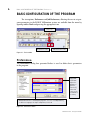
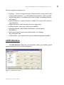
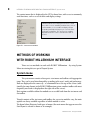
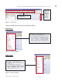
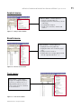
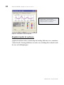
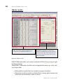
Getting started GUIDE Synopsis: The purpose of this Manual is introduce the novice user to the ROBOT Millennium system and to provide some guidance into the program configuration, menu system and navigation techniques. It will also show the many and varied methods of input of data and extraction of results. It is assumed that ROBOT Millennium Version 20.1 or ROBOT Millennium Free is installed on the PC–to find out more about licensing, please contact [email protected]. GENERAL DESCRIPTION OF THE PROGRAM General description of the program What is ROBOT Millennium? ROBOT Millennium is a single integrated program used for modeling, analyzing and designing various types of structures. The program allows users to create structures, to carry out structural analysis, to verify obtained results, to perform code check calculations of structural members and to prepare documentation for a calculated and designed structure. ROBOT Millennium – key features of the Commercial version are shown below: Linear, nonlinear and dynamic (modal, spectral, seismic, time history, push over, P-Delta, buckling deformation, plasticity) structure analysis working in a multilingual environment (15 languages independently set to user interface, designing and calculation notes) working in a multinational environment - designing according to over 40 design codes frames, plates and shells, plus a powerful GUI modeler and mesher allows the user to define virtually any shape or configuration of structure – you analyze the true structure geometry quality bi-directional integration with Revit® Structure, plus integration through IFC, CIS2 etc. an open API to allow the user to interface their own applications for pre and/or post processing ROBOT Millennium modules ROBOT Millennium is a single product with many functions and a common user environment. Once ROBOT Millennium is activated (click on the appropriate icon on the desktop or choose the appropriate command from the taskbar), the window shown below (Figure 2.1) will appear on the screen. The window is used to select the type of structure that will be analyzed or to load an existing structure. ROBOT Millennium - Getting Started Guide ROBOT MILLENNIUM MODULES Figure 2.1 - ROBOT Millennium modules window NOTE: When the cursor is positioned on an icon, a short description of its function is displayed. The most commonly used icons are described below: 2D Frame Analysis 2D Truss Analysis Grillage Analysis 3D Truss Analysis 3D Frame Analysis 2D FE Plate Analysis Shell Analysis – used to model surfaces of any shape in 3d structures Open the previously created project file Open a new project Table 2.1 - ROBOT Millennium basic modules The ROBOT Millennium Freeware version offers many of the possibilities of the commercial product: ROBOT Millennium - Getting Started Guide ROBOT MILLENNIUM SCREEN LAYOUT Linear analysis 2D and 3D frames – up to 200 beams FE plates and shells (floors, walls etc.) – up to 1500 nodes English language interface Section libraries from around the world ROBOT Millennium API to allow users to integrate their own pre or post processing tools Various upgrades are offered to add the additional functionalities of the commercial version, or to benefit from product support. ROBOT Millennium screen layout STANDARD toolbar – these options are mainly associated with non structural items, such as print, save, undo etc. edit, view, tools, preferences GRAPHIC VIEWER / EDITOR OBJECT INSPECTOR – management of structural objects Layout System – designed to take the new user through a model from start to finish, while opening predefined windows for selected tasks VIEW MANAGER – selection of a work plane; switching between 2D and 3D view Figure 3.1 - ROBOT Millennium typical screen layout ROBOT Millennium - Getting Started Guide STRUCTURE MODEL toolbar – sections, nodes, members, supports, loads etc. BASIC CONFIGURATION OF THE PROGRAM | Preferences Basic configuration of the program The two options, Preferences and Job Preferences, allowing the user to set program parameters in the ROBOT Millennium system, are available from the menu by opening toolbar Tools and pressing the appropriate icon: Tools icon Preferences icon Job Preferences icon Figure 4.1 - Tools toolbar Preferences: The Preferences dialog box presented below is used to define basic parameters in the program: Regional settings adjust the databases (profiles, materials), units and codes to the standards of a country ROBOT Millennium is a multilingual program – the user can independently set different languages for input and printout, if desired Figure 4.2 - Preferences menu ROBOT Millennium - Getting Started Guide BASIC CONFIGURATION OF THE PROGRAM | Job Preferences The most regularly used options are: languages - selection of regional settings (definition of the country whose codes materials and regulations - e.g. code combination regulations - will be used during the design process, calculations and structure design) and working and printout language general parameters (saving parameters, number of recently used structures, sound on/off etc.) display parameters (colors and fonts for screen components) toolbar and menu (menu type and the type of toolbars) printout parameters (colors and fonts for printouts, scale and symbols, line thickness) protection parameters (protection, authorization) - for changing the system protection COM interface - presentation of the registered additional programs/modules Job Preferences: The Job Preferences dialog box, presented below, allows you to define general program parameters to be used in a given project: Figure 4.3 - Job Preferences menu ROBOT Millennium - Getting Started Guide NAVIGATION TECHNIQUES The most important functions are: number units and formats (dimensions, forces, possibility of unit edition) materials (selection of material set, according to the country and the possibility of creating user-defined material) section database (selection of the appropriate database with member sections) structure analysis parameters (selection of the static analysis method and definition of basic parameters for dynamic and non-linear analysis; selection of analysis types, possibility of saving results for seismic analysis – combination of seismic cases) parameters for generation of surface finite element meshes for plates and shells Navigation techniques In the ROBOT Millennium software, various mechanisms have been introduced to make structure definition simple and more efficient. According to the type of operation performed, the mouse cursor changes its shape to: “hand” – a selection mode for highlighting entities “cross pointer” - during node and bar definition, to define precise points e.g. start and end points of members shape of the appropriate feature e.g. when adding sections the cursor is in shape of an I section, when adding supports a support icon appears etc. The cursor operation in a viewer by means of the third mouse button (or wheel) is identical to that in the AutoCAD® program. The following cursor support modes are available: wheel rotation – zoom in / out wheel rotation + Ctrl key – horizontal pan wheel rotation + Shift key – vertical pan pressing the third button - pan double-click with the third button – initial view ROBOT Millennium - Getting Started Guide NAVIGATION TECHNIQUES The user should take note of the work capabilities in 3D views when the menu option Dynamic View (View → Dynamic View → Dynamic View) is switched on. 3D viewing enables work in one of five modes: four simple modes: 3D rotation, 2D rotation, zoom and pan one multi-function mode The user may switch from one work mode to another by selecting an appropriate option in the View / Dynamic View menu, on the View toolbar and in the context menu. After choosing a work mode, the mouse cursor movement (with mouse left button pressed) brings about the relevant change in the 3D view: 3D Rotation – rotates a structure in all planes 2D Rotation - rotates a structure in the plane parallel to the screen plane Zoom – movement down the view – zooming in / zooming out a structure to / from the screen plane Pan – movement in the view plane (structure shift with respect to the screen center) The multi-function mode (Rotation / Zoom / Pan) enables work using all the modes at the same time. The viewer of 3D view is divided into quarters and each of them is ascribed one of the modes: top left: 3D rotation top right: pan bottom left: zoom bottom right: 2D rotation Table 5.1 - Cursor modes Once the cursor is positioned in the relevant quarter of the screen, the cursor shape changes (see the icons above). While working with the graphic editor or a table, clicking the right mouse button opens an additional context menu containing the most widely used options. ROBOT Millennium - Getting Started Guide METHODS OF WORKING WITH ROBOT MILLENNIUM INTERFACE | System menu The context menu that is displayed in the GUI is shown here, with access to commonly used functions, such as access to tables and display settings. CONTEXT MENU that is displayed in the GUI is shown here, with access to commonly used functions, such as coursor modes, access to tables or display settings. It speeds up work by offering easy access to the most frequently used options. The content of the window depends on whether it was activated from a table or the GUI. Figure 5.1 - Context menu window Methods of working with ROBOT Millennium interface There are two methods to work with ROBOT Millennium - by using System Menu to entering data, or special Layout System. System menu The system menu consists of two parts: a text menu and toolbars with appropriate icons. They can be used interchangeably, according to the users’ needs and preferences. Both are displayed in the same way - as a horizontal bar at the top of the screen (additionally, for some layouts in the ROBOT Millennium system, another toolbar with most frequently used icons is displayed on the right side of the screen). Basic options available within the modules are accessible both from the text menu and the toolbar. Though contents of the text menu and toolbars for successive modules vary, the main options are always available regardless of which module is active. The figure below illustrates both types of menus (the main menu that appears once the Start layout is selected is shown as an example): ROBOT Millennium - Getting Started Guide METHODS OF WORKING WITH ROBOT MILLENNIUM INTERFACE | System menu STRUCTURE MODEL bar - additional side toolbar with most frequently used icons SYSTEM MENU – text menu & standard toolbar Figure 6.1 - System menu Options available in the text menu are grouped as follows: File menu: FILE MENU – contains options for: File management (New, Open, Save etc.) Calculation notes and drawing printouts (Screen Capture..., Printout Composition... etc.), a list of information about project and a list of recently open files Figure 6.2 - File menu window Edit menu: EDIT MENU – contains options for: Elements edition (Undo, Redo, Cut, Copy etc.) Selection (Select...,Select All) Selection using filters (Select Special) Model modification (Edit, Complex Edit..., Divide, Intersect etc.) Figure 6.3 - Edit menu window ROBOT Millennium - Getting Started Guide 10 METHODS OF WORKING WITH ROBOT MILLENNIUM INTERFACE | System menu View menu: VIEW MENU – contains options for: 2D/3D view management of a structure’s model (Dynamic View, Zoom, Pan etc, Work in 3D) Structure attributes to be presented on the screen (Display); definition of grid parameters (Grid) Selection of tables with data or results (Tables) and saving defined views of a structure (History) Figure 6.4 - View menu window Geometry menu: GEOMETRY MENU - contains options to: Select or modify a type of a structure Define a model construction axis (Axis Definition) Define structural data - nodes, bars, panels and auxiliary objects Define materials Define bar profiles and their orientation and direction of local coordinate system Define supports and many other structural items Figure 6.5 - Geometry menu window Loads menu: LOADS MENU – contains options to define load cases and combinations Figure 6.6 - Loads menu window ROBOT Millennium - Getting Started Guide METHODS OF WORKING WITH ROBOT MILLENNIUM INTERFACE | System menu Analysis menu: ANALYSIS MENU – contains options to: Start the calculation process Change from linear to non linear, P-Delta or buckling Set up dynamic analyses Design concrete beams, columns and surfaces Figure 6.7 - Analysis menu window Results menu: RESULTS MENU – contains options to: Display beam results graphically Display detailed results for beams graphically Display results for surfaces Display tables that easily be edited, sorted, filtered, exported to MS Excel® etc. Figure 6.8 - Results menu window Tools menu: TOOLS MENU – contains different types of configuration options (Preferences, Job Preferences…) and possibility to define user’s interface, menu, shortcuts and form of calculation notes Figure 6.9 - Tools menu window ROBOT Millennium - Getting Started Guide 11 12 METHODS OF WORKING WITH ROBOT MILLENNIUM INTERFACE | Layout System Window menu: WINDOW MENU – offers options to manage and arrange the graphic windows and an option to activate/deactivate the “Object Inspector” Figure 6.10 - Window menu Help menu: HELP MENU – contains help options and various product information items Figure 6.11 - Help menu window Layout System The second method of work with ROBOT Millennium is by using the special layout system. ROBOT Millennium has been equipped with a layout mechanism that simplifies the design process. The layouts in ROBOT Millennium are specially designed systems of dialog boxes, viewers and tables that are used to perform specific defined operations. Layouts available in ROBOT Millennium were created to make consecutive operations leading to defining, calculating, and designing the structure easier – the layouts guide the user through the process from model generation to results. In order to make the system as easy to use as possible, each layout has its own predefined set of windows which are automatically opened on entering the layout and closed on exit. ROBOT Millennium - Getting Started Guide METHODS OF WORKING WITH ROBOT MILLENNIUM INTERFACE | Layout System Layouts are available from the selection list found in the right, upper corner of the screen: SYSTEM LAYOUT SELECTION WINDOW A list of standard layouts available in ROBOT Millennium. This example shows the layouts for a shell structure and the layouis vary depending on the structure type Figure 6.11 - System layout selection window The layout order and arrangement follows a chronological process, starting from defining nodes, beams, then supports, sections etc. DEFINITION OF STRUCTURE MODEL Contains layouts relating to the geometry and basic definition of a structural model, such as supports, sections etc. RESULTS Contains layouts showing beam results, maps on surfaces etc. DESIGN Contains layouts relating to steel and concrete design, slab design etc. Figure 6.12 - System layout selection window - chronological layout order A typical layout for nodes is shown – note that each window cannot be closed until a new layout is selected. ROBOT Millennium - Getting Started Guide 13 14 METHODS OF WORKING WITH ROBOT MILLENNIUM INTERFACE | Layout System Layout selection pull down menu – in this case layout Nodes is selected graphic viewer / editor Dialog boxes to show entered data. It is also possible to enter data manually in this screen or to paste from programs such as MS Excel® STRUCTURE MODEL toolbar – this (as in other layouts) contains data relating to structural entities, but limited to the type of data that is appropriate to node definition Figure 6.13 - Typical layout for nodes However it is not necessary to define the structure according to the layout order. This may be done in any order chosen by the user. The layout system was introduced in such a way that ROBOT Millennium structure definition is intuitive and efficient. All ROBOT Millennium operations may be performed without using the defined layouts but by using system menu instead or also taking advantage of both methods (simultaneously) according to the user’s needs and preferences. ROBOT Millennium - Getting Started Guide ENTERING THE STRUCTURAL ANALYSIS DATA Entering the structural analysis data There are 3 ways to enter data: 1. By entering data using the appropriate text dialog box or direct in a table (or pasted from MS Excel®) 2. By entering data in the ROBOT Millennium GUI – using tools for graphic structure definition - i.e. snap grids or structural axes. Examples of data entering using the System Layout mechanism (for Bars and Loads options) are presented below: ROBOT Millennium - Getting Started Guide 15 16 ENTERING THE STRUCTURAL ANALYSIS DATA Graphic viewer/editor allows the user to enter and view data Dialog box to load cases definition Dialog box to define different types of loads (node, beam, surface, self-weight) Data concerning defined load cases (case, load type etc.) in tabular form Toolbar with load tools (including advanced options such as soil loading, vehicle loading etc.) Figure 7.2 - Examples of loads data entering with System Layout mechanism NOTE: The updating of data is dynamic – tables reflect graphics and vice versa at all times. ROBOT Millennium - Getting Started Guide ENTERING THE STRUCTURAL ANALYSIS DATA 3. By entering data in another application and importing into ROBOT Millennium several file formats are supported including: DXF, DWG, IFC, SDNF (steel detailing neutral file), CIS/2. A dynamic link to and from Revit® Structure also provides bi-directional integration. As the preparation of the structural model progresses, the user can control exactly what is seen on the screen by using the Display settings (it is available by pressing from context menu or direct from the bottom, right corner on the RM screen): icon DISPLAY allows the user to switch on and off a wide selection of items, including node and members numbers, section shapes, supports, FE mesh and also sets up hidden line and render options. A wide range of customization options allows to the user to define a view of structure as required exactly to user’s preferences. Figure 7.3 - Display window After defining the model data, the user now proceeds to the analysis stage. However, prior to this stage, the model must be “discretized” into finite elements. ROBOT Millennium has wide ranging capabilities for “automeshing” the structure and meshing is generally a very fast process for even the largest of models. Some of the “meshing parameters are shown below: ROBOT Millennium - Getting Started Guide 17 18 ANALYZING THE STRUCTURE Example of structure with meshed panels is shown below: Figure 7.5 - Example of meshing Analyzing the structure Structural analysis can be started by selecting one of the two “calculation” buttons in the horizontal toolbar. Figure 8.1 - Calculation icons ROBOT Millennium - Getting Started Guide ANALYZING THE STRUCTURE The icon on the left side starts the calculation process. The second icon is used to set different analysis parameters. This option allows the user to change specific analysis types from linear to non linear or to set up dynamic analysis. Figure 8.2 - Changing analysis parameters As a default, all analysis is set as “linear static”, unless the user has included some members or parameters such as cables, tension only, hinges etc. In such a case the analysis type is automatically changed to “non linear” and ROBOT Millennium will apply the loads incrementally to ensure the true structural equilibrium and a final exact geometry is reached. ROBOT Millennium has many non linear parameters that the user can set in the case of non convergence of analysis data, including the options to set full or modified NewtonRaphson and “step halving”. In addition to general non linear calculations, the user can also set the following analysis options: P-Delta Modal Seismic (to codes such as IBC, UBC, EC etc.) Spectral response Time history Buckling ROBOT Millennium - Getting Started Guide 19 20 RESULTS PREVIEW | Graphical results for beams Results preview The Results Layout shows a wide range of analysis results presentation. NOTE: All of results preview options are also available through the RESULTS pulldown menu. User can view results of calculations by selecting the results layout, where a set of submenus for particular results then appears Figure 9.1 - Results type selection from results layout Results can be split into various categories, each having their own characteristics. Graphical results for beams: (graphical results for individual beams, or selection of beams, or groups of beams presentation - bending moment, shear, stress, deflection animation of results in .avi format etc.) ROBOT Millennium - Getting Started Guide RESULTS PREVIEW | Graphical results for beams Graphical presentation of results as diagrams in graphic viewer/editor Tables of results – can easily be converted to MS Excel® format by clicking right hand mouse Dialog box selects type of result to be displayed Side toolbar shows additional results of structural analysis in tabular form, graphical form, plus links to design modules Figure 9.2 - Results in the diagrams form There is also easy acces to calculation results for single bars. In context menu of the bar (right mouse click on the element, then select Object Properties option) user can see diagrams and values for selected quantity of internal forces. ROBOT Millennium - Getting Started Guide 21 22 RESULTS PREVIEW | Graphical results for surfaces A right mouse click on any bar displays its properties and results (if analysis has been carried out) Figure 9.3 - Calculation results for single bar Graphical results for surfaces: (graphical results for surfaces, contour maps for bending, deflection, stress, animations; ”reduced results” showing global forces in surface cuts, including direct reduced results for cores and stiff diaphragms) ROBOT Millennium - Getting Started Guide RESULTS PREVIEW | Graphical results for surfaces Graphical presentation of result maps in graphic viewer/editor Dialog box to select type of map to display Side toolbar shows additional results of structural analysis in tabular form, graphical form, plus links to design modules Figure 9.4 - Results in the maps form ROBOT Millennium - Getting Started Guide 23 24 RESULTS PREVIEW | Tabular results Tabular results: Tables can easily be edited, enveloping results, setting limits, filtering data by load case etc. Dialog box used to define contents of the table. It is available from the menu activated by pressing the right mouse button when the cursor is located in the table, and selecting TABLE COLUMNS Figure 9.5 - Tabular results ROBOT Millennium tables can be easily transferred to MS Excel® by pressing the right hand mouse button. Inside ROBOT Millennium, the tables can be manipulated in many ways, in the same way as input tables: filtering data for specific load cases, members or groups of members filtering data inside or outside user defined limits showing global maxima and minima for selected members, nodes or surfaces ROBOT Millennium - Getting Started Guide REPORTS AND PRINTOUT COMPOSITION Reports and printout composition ROBOT Millennium has a built in “report generator” which permits the user to create a user defined printout for a Project. There are two options on the menu bar - “Printout Composition” and “Screen Capture” which help to prepare the final calculations notes, tables and graphic printouts. Dialog box used to define contents of the table - it is available from the menu activated by pressing the right mouse button when the cursor is located in the table, and selecting TABLE COLUMNS Tables can easily be edited, enveloping results, setting limits, filtering data by load case etc. Figure 6.2 - Printout Composition and Screen Capture icons The Standard tab lists a set of predefined options for printout, which can be mixed with screen captures to the user’s requirements. List of final printout, showing order of data to be printed - the dashed red line indicates a page break between each item Predefined list of printout components Figure 6.2 - Printout composition ROBOT Millennium - Getting Started Guide Various method of saving the report – in .doc, html and sxw formats 25 26 ADVANCED ANALYSIS AND DESIGN A key feature of ROBOT Millennium is that all of the data in the program is saved in a common binary file – this data includes input, output, design plus also printout data. When structural data is altered or amended the output and printout (tables and graphics) are automatically updated on re-analysis to reflect the new results of the analysis. This is particularly useful when considering a schematic design or “sensitivity study” since the printout is automatically updated at every analysis step to reflect the current structural configuration. Advanced analysis and design Following analysis of the structure, the user may wish to take advantage of many of the additional features – such as: Steel design Concrete design for beams, columns, floors Advanced analysis – P-Delta, dynamic etc. These items are beyond the scope of this “Getting Started Manual” and are covered in more depth in the “User Manual of ROBOT Millennium”. ROBOT Millennium - Getting Started Guide LIST OF SHORTCUTS List of shortcuts In order to Press select all copy a text or a drawing open a new project open an existing project start printing save the current project cut a text or a drawing repeat the last operation paste a text or a drawing undo the last operation display the 3D view of a structure (3D XYZ) project a structure on XZ plane project a structure on XY plane project a structure on YZ plane zoom in the structure view on screen display the initial view of the structure (defined by the initial angles and scale) “exploded” view of structure elements (on/off) zoom window turn on/off section drawing display screen capture zoom out structure view on screen turn on/off section symbol display rotate continuously around the X axis rotate continuously around the Y axis rotate continuously around the Z axis delete a text or a drawing call ROBOT Help system for the active option in the active dialog box call text editor reduce structure attributes (supports, numbers of nodes, bars, loads) presented on screen enlarge structure attributes (supports, numbers of nodes, bars, loads) presented on screen Ctrl + A Ctrl + C Ctrl + N Ctrl + O Ctrl + P Ctrl + S Ctrl + X Ctrl + Y Ctrl + V Ctrl + Z Ctrl + Alt + 0 Ctrl + Alt + 1 Ctrl + Alt + 2 Ctrl + Alt + 3 Ctrl + Alt + A Ctrl + Alt + D ROBOT Millennium - Getting Started Guide Ctrl + Alt + E Ctrl + Alt + L Ctrl + Alt + P Ctrl + Alt + Q Ctrl + Alt + R Ctrl + Alt + S Ctrl + Alt + X Ctrl + Alt + Y Ctrl + Alt + Z Del F1 F9 PgDn PgUp 27