1
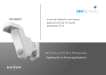
1. Introduction
IMPORTANT
• Some functions are only available with control panel versions 2.0.0 or later (enter
on the control
panel keypad to check the version).
• Operational differences in relation to former ranges are described in the compatibility booklet available in the Daitem Installers
section at www.daitem.co.uk.
The vocal keypad with tag reader and proximity detector can be used to operate an intrusion protection system from outside
or inside the home.
The keypad commands can be accessed:
• using the master code,
• using the 8 user codes,
• using a tag (24 tags max).
Each command is confirmed with a voice message and a visual signal (LED) issued by the keypad. The keypad indicates:
• the system status,
• the status of alarms,
• the status of exit points,
• faults.
The speech synthesis system also helps with keypad use and programming.
The vocal keypad also has an infrared detector able to detect an approaching person.
The keypad is protected against:
• opening,
• removal,
• attempts to discover the access code.
If the level of lighting is low, a key is pressed or the detector triggered (see Infrared detector operation), the buttons and
keypad are back-lit for 10 s.
The back-lighting period is repeated for 10 s when the last key is pressed.
Infrared detector
Two-colour LED
8 command keys
can be personalised
Arm
Disarm
Buttons
for access codes
and programming
Partial 1
Partial 2
Arm Presence
System status query
Not allocated
Not allocated
Blue light
LED and pictogram
indicating tag reading zone.
1.1 LED indications
LED
Red
Green
LED status
steady
1 flash every 5 s
2 flashes every 10 s
3 quick flashes
steady for 2 s
steady for 10 s
Meaning
key pressed correctly
keypad in test mode
keypad in installation mode
handling or programming error, access code invalid
correct programming
access code valid (the 10 s period is repeated after each command)
2
1.2 Voice messages
IMPORTANT: only the commands sent from the vocal keypad result in the following messages. Orders issued by another remote
control unit do not lead to a keypad response.
The keypad issues the following voice messages:
Following a command
Disarm
Arm
Partially arm 1
Partially arm 2
Disarm group X (X = 1 to 8)
Arm group X (X = 1 to 8)
Arm presence
System status query
Change to test mode
Change to installation mode
Change to user mode
Voice message
“bip, off”
“bip, armed”
“bip, armed partial one”
“bip, armed partial two”
“bip, off group X”
“bip, armed, group X”
“bip, armed presence”
“bip, system status, armed”
“bip, system status, armed partial one two”
“bip, system status, off”
“bip, system status, armed group X”
“bip, system status armed presence”
“bip, test mode”
“bip, installation mode”
“bip, user mode”
It also indicates:
• possible alarms following a Disarm command
Following a command
Disarm...
Voice message
“bip, off ..., alarm System”
• faults and the status of exit points following a Disarm, Arm or system status query command
Following a command
Disarm...
Arm...
System status query
Voice message
“bip, off ..., fault system”
“bip, armed ..., fault system”
“bip, armed ..., exit opened”
“bip, system_ status..., fault system”
“bip, system status..., exit opened”
“bip, system status..., exit inhibited”
Example:
The system is in Armed Partial Two mode and the keypad has a battery fault.
When a “System status query” order is sent from the vocal keypad, the keypad and control panel issue the following messages:
“Bip, System_status, Armed Partial
Two, bip, on 12/03 at 12 PM, Fault
Voltage Remote_control_unit 1”
“Bip, System_status,
Armed Partial Two, bip,
Fault System”
The keypad also indicates information feedback as shown below:
Command sent to:
LED status and colour
Meaning
An alarm control panel
lights up steady GREEN for 1.5 s
Total or group DISARMING
flashes GREEN 3 times
Total or group DISARMING with alarm memory
lights up steady RED for 1.5 s
Total, partial or group ARMING
flashes RED 3 times
ARMING blocked (1)
lights up steady GREEN for 1.5 s
Transmission of a home control command
(light, relay, etc.)
A command receiver
or remote-controlled socket
(1) Arming blocked means that the intrusion system has been unable to arm owing to a system fault.
The user must check the control panel for more information.
3
1.3 Infrared detector operation
The vocal keypad has an infrared detector enabling it to detect an approaching person.
It has 2 distinct detection zones:
• The close detection zone
• The distant detection zone
Top view
Top view
1.2 m
0.5 m
0.4 m
2m
Side view
Side view
0.5 m
0.3 m
2m
0.2 m
0,8 m
1.8 m
1.6 m
1.3 m
1.3 m
For an efficient close
detection, infrared
detector must not be
installed at height upper
than 1.3 m.
IMPORTANT: if the infrared detector is directed at the sun it is likely to be triggered for no reason.
Like a conventional infrared motion detector, the keypad
detector is allocated to an intrusion group and its alarm level
can be set.
Different types of triggering are possible:
• immediate,
• delayed,
• combined.
Time-delayed triggering
In the event of intrusion, the alerts and deterrents are
triggered at the end of the entry time delay.
IMPORTANT: it is not advisable to programme the infrared
detector for immediate triggering.
keypad
window
4
door
Combined triggering
A combined detector will trigger immediately if it is the first detector to be set off. It will observe a time delay before
triggering if another time-delayed detector detects something first.
Example:
• The user enters his home:
The door/window detector detects his presence and
the keypad motion detector observes a time delay
allowing the user to reach the keypad and stop the
system.
time-delayed
door/window
detector
• In the event of intrusion via a window:
The door/window detector is not set off whereas the
keypad motion detector is immediately triggered
along with the other alerts and deterrents.
time-delayed
door/window
detector
door
window
keypad
door
keypad
window
Depending on the alarm system status, the keypad will operate as follows:
1. Alarm system status: Disarmed
Detection
Keypad response
Distant
No response
Close
Back-lighting for 10 s
2. Alarm system status: Totally Armed or Group to which the keypad infrared detector has been allocated Armed:
Keypad response
Detection
Infrared
detector
alarm level
Time-delayed
triggering of infrared
detector
(detector programmed
for time delay or
combined operation
and triggered 2nd)
Intrusion
Prealarm
Distant
or
close
Deterrence
Warning
Immediate triggering
of infrared detector
(detector programmed
for combined
operation
and triggered 1st)
no response
• back-lighting
for 10 s
• warning message
“bip, bip, bip,
protection active” (1)
Control panel
response
loud sounding
for 90 s
Siren response
loud sounding
for 90 s + strobe
flashing for 15 min
• back-lighting for 10 s loud sounding
• series of 10 beeps (1) for 15 s
loud sounding
for 15 s + strobe
flashing for 15 s
• back-lighting for 10 s series of beeps
• series of 5 beeps (1) for 5 s
series of beeps
for 5 s + strobe
flashing for 5 s
• back-lighting for 10 s series of beeps
• series of 3 beeps (1) for 2 s
series of beeps
for 2 s + strobe
flashing for 5 s
(1) IMPORTANT: the message or warning beeps are issued if parameter 23 has been enabled (factory disabled).
5
2. Preparation
2.1 Tooling required
6 mm
PH.1
2.5 mm
IMPORTANT: the fixing screws
and plugs are not provided.
2.2 Power supply
1. Unclip the front panel
from the bottom.
2. Remove the front panel.
3. Loosen the 2 screws.
4. Remove the electronic part
from the base.
Philips PH.1
5. Remove the pre-cut part of the sticker and
stick it to the guarantee certificate inside
the user manual supplied with the control
panel. If you are adding to an existing
system, use the guarantee certificate
supplied with this product.
6. Connect the lithium power pack to its support.
SH640AX
A1235A04823
SH640AX
Coller sur certif
A1235A04823
6
7. Push the lithium power pack lock downwards.
The keypad will issue a long beep
and the LED will light up RED for 2 s.
“bip”
3. Changing the operating mode
IMPORTANT
• When the keypad is powered it is in user mode.
• The keypad must be in installation mode for recognition programming and parameter-setting.
The mode can be changed by entering the factory master code “0000” then the factory installer code “1111” as shown
below:
installer code
INSTALLATION
MODE
USER MODE
2 flashes
every 10 s
ins
tal
ler
ins
tal
ler
Operating
mode on
power-up
co
de
co
de
de
co
ter
s
ma
de
co
ter
s
ma
TEST MODE
1 flash
every 5 s
IMPORTANT
• For security reasons, the keypad automatically switches back to user mode after 4 hours without a command being
issued.
• If 5 wrong codes are entered in less than 5 minutes the keypad will be blocked for 5 minutes.
• If the keypad:
- is used without a control panel (e.g. command from external receiver),
- is not or no longer recognised by a control panel,
the operating mode cannot be changed if the tamper pin on the back of the keypad is pressed in.
7
4. Recognition programming
IMPORTANT: the product does not need to be placed next to the control panel for recognition programming. In fact, it is
advisable to move it at least 2 metres away from the control panel.
Recognition programming allows the control panel to recognise the keypad and infrared detector.
1. Make sure the control panel is in
installation mode (see Control panel
installation manual) with its front cover
removed.
2. Switch the keypad to installation mode by entering:
“bip,
test mode”
master code
(factory: 0000)
then
“bip, Installation
mode”
installer code
(factory: 1111)
3. Perform the following recognition programming procedure:
“bip, remote control
unit X, bip, detector X”
“group?”
“time delay?”
“bip, remote control
unit X, bip, detector
X, group Y (immediate, time delayed
or combined)”
“bip”
)))
))
then
to
or
or
10 s max.
Press * then #
on the control
panel keypad
Press and hold
“Off” until the
control panel
responds
The control
panel issues a
voice message
to confirm
keypad
recognition
The control panel
waits to know the
infrared detector
group (from 1 to 8
according to the
type of control
panel). Press the
control panel keypad
to select the group
The control panel waits to
know the type of infrared
red detector triggering:
• 0: immediate,
• 1: time-delayed,
• 2: combined.
Press the control panel
keypad to select the type
The control
panel issues a
voice message
to confirm
infrared detector
recognition
The keypad
issues a long
beep to
confirm
recognition
IMPORTANT
• It is not advisable to programme the infrared detector for immediate triggering.
• The control panel issues 3 short beeps to indicate a programming error. If this happens, the recognition programming
procedure should be performed again from the start.
8
5. Parameter-setting
IMPORTANT
• Before setting any parameters, the keypad must first be in installation mode (see chapter 3. Changing the operating mode).
• A long beep is issued and the LED lights up green for 2 s to indicate correct programming. If an error is made, the red LED
flashes 3 times and the keypad issues 3 short beeps.
5.1 Selecting the language
To select the speech synthesis language, enter:
0: French (factory) 3: Spanish
1: Italian
4: Dutch
2: German
5: English
5.2 Setting the speech synthesis system sound level
To set the speech synthesis system sound level, enter:
1 = low level
4 = average level (factory)
8 = high level
IMPORTANT
• This setting does not affect the sound level of the standard beep issued each time a
keypad key is pressed.
However, it does affect the sound level of the short beep, long beep and 3 error
beeps issued during programming.
• Below -5°C, the sound level automatically switches to low.
5.3 Number of access code digits
IMPORTANT: the number of access code digits can only be modified when all the access codes correspond to the factory
values. To do this, put the keypad in installation mode and enter:
.
Before modifying the keypad access codes, the number of access code digits must be determined (4 digits in the factory
code).
If you extend the number of digits this will apply to all the following:
• the master code,
• the installer code,
• the 8 user codes.
To modify the number of digits, enter:
number of digits (4 to 6)
Example: to extend the access codes to 6 digits, enter:
5.4 Modifying the master code
IMPORTANT
• Forbidden access codes: 0000, 1111, 2222, 3333.
• The master code can be modified in the three operating modes: installation mode, test mode or user mode.
The master code is for use by the main user and enables:
• use of all keypad functions (all commands),
• access to TEST mode and USER mode,
• control (authorisation or non-authorisation) of User codes.
To ensure system confidentiality, the master code must be changed. To do this, enter:
old code
new code
new code
Example: to replace the factory master code “0000” with the new code “1234”, enter:
9
5.5 Modifying the installer code
The Installer code is for use by the installer.
It allows access to all keypad installation, programming and maintenance operations in INSTALLATION mode.
To ensure system confidentiality, the installer code must be changed.
To do this, enter:
new code
old code
new code
Example: to replace the factory installer code “1111” with the new code “6789”, enter:
5.6 Managing user codes
IMPORTANT: there are no factory programmed user codes.
The user codes are for secondary and occasional users (service staff, employees, etc.).
They allow for limited and temporary use of the keypad:
• restricted access to specific commands or specific groups can be programmed for each user code,
• each user code can be enabled or disabled at any time.
The vocal keypad has 8 user codes.
To programme or modify a user code, enter:
master code
1 to 8 (choice
of user number)
user code
user code
Example: after entering the master code (1234), programme user number 1 (1213) by entering:
5.6.1 Disabling and enabling a user code
User codes can be disabled or enabled in the 3 operating modes.
A programmed user code is automatically enabled.
To disable or enable a user code, enter:
master code
1 to 8 (choice
of user number)
0: disabled
1: enabled
Example: to disable user code 1, enter:
5.6.2 Restricted access to commands
User codes can have separate limited access to:
• specific keypad command keys,
• specific groups.
Only selected commands or groups can be accessed when the user code is entered.
• To restrict a user code to (a) specific command key(s), enter:
...
master code
1 to 8 (choice
of user number)
user code
command
key(s)
user code
Example: to restrict user code 1 (1213) to the Partial 1 command, enter:
In this case, only the Partial 1 key can be accessed via user code 1.
• To restrict a user code to (a) specific group(s), enter:
...
master code
1 to 8 (choice
of user number)
user code
user code
groups 1 to 8 depending
on the type of control panel
Example: to restrict user code 1 (1213) to Group 1 and Group 2, enter:
In this case, user code 1 can only disarm and arm Group 1 and Group 2.
10
5.6.3 Restricted access to both a command key and a group
Example: to restrict user code 1 (1213) to Group 1 Arm/Disarm and the Partial 1 key, enter:
In this case, user code 1 can only disarm or arm Group 1
and operate the Partial 1 key.
“Partial one”
command key
Group 1
5.7 Managing tags
Tags dispense with the need for users to enter the master code or user codes when issuing commands.
Each tag can be programmed for restricted access to specific commands or specific groups.
Each tag can be enabled or disabled at any time.
The vocal keypad can work with up to 24 tags maximum.
IMPORTANT
• The tag numbers are automatically allocated by the keypad in increasing order.
• When a tag is deleted this frees up a number, which will be automatically re-allocated when a new tag is registered.
5.7.1 Registering and deleting tags
For a tag to be identified by the keypad, it must first be registered. The registering procedure described below must be
performed for each tag. If the installation has several keypads and a tag must operate with each one, the tag registering
procedure must be performed for each keypad.
Perform the tag registering procedure in installation mode.
1. Press
then
on the keypad.
Perform step 2 within the next 10 s.
2. Hold the tag against the
zone indicated by the
flashing LED.
3. The keypad issues a beep
and announces the tag
number.
“bip, tag n°”
• To delete a registered tag, enter:
tag n° from 01 to 24
The keypad issues a long beep to indicate that the tag has been deleted.
• To delete all registered tags, enter:
5.7.2 Checking tags
Once the keypad is in user mode, a tag number can be checked at any time by performing the following procedure:
1. On the keypad, enter:
2. The LED indicating the reading zone
flashes. Place the tag against the
pictogram
.
3. The keypad issues a long beep and
announces the tag number.
“beeep, tag n°”
master code
11
5.7.3 Disabling and enabling a tag
Tags can be disabled or enabled in the 3 operating modes.
A registered tag is automatically enabled.
To disable or enable a tag, enter:
master code
tag n° from
01 to 24
0: disabled
1: enabled
Example: to disable tag 1, enter:
5.7.4 Restricted access to commands
Tags can have separate and limited access to specific command keys and specific groups.
Only commands or groups selected during programming can be accessed using a tag.
• To restrict a tag to (a) specific command key(s), enter:
...
master code
tag n° from
01 to 24
command
key(s)
tag n° from
01 to 24
Example, to restrict tag 02 to the Partial 1 command, enter:
In this case, only the Partial 1 key can be accessed via tag 02.
• To restrict a tag to (a) specific group(s), enter:
...
master code
tag n° from
01 to 24
tag n° from
01 to 24
groups 1 to 8 depending
on the type of control panel
Example, to restrict tag 01 to Group 2, enter:
In this case, tag 01 can only disarm and arm Group 2.
• To cancel tag restrictions, enter:
master code
tag n° from
01 to 24
tag n° from
01 to 24
Example, to cancel the restrictions linked to tag 02, enter
In this case, the access restrictions linked to tag 02 are deleted.
5.7.5 Combined command key and group restriction
Example, to restrict tag 01 to Arming/Disarming Group 1 and the Partial 1 key, enter:
In this case, tag 01 can only disarm
or arm Group 1 and operate
the Partial 1 key.
Group 1
“Partial one”
command key
12
5.8 Personalising a command button
The 8 keypad command keys can be personalised to adapt keypad commands to user needs (see table below).
Furthermore, this personalisation allows the user to choose between direct or code-based access to keypad commands.
To personalise a key, enter:
IMPORTANT
Key to be
personalised
Command number
(see table below)
Command description
• In installation mode, the keypad commands can be
accessed directly.
• In User mode all Arm or Disarm commands as well as the
System Status command can only be accessed by using a
User code.
Type of access:
0: direct access
1: code-based access
Command n°
Command description
Command n°
Command description
Command n°
OFF (1)
21
Light ON
54
Armed relay 3
84
Panic Alarm
22
Light toggle switch
56
Toggle switch relay 3
86
Armed (1)
23
Light timer
58
Timer relay 3
88
Silent alarm
24
Pulse relay 1
60
Pulse relay 4
90
Armed, Partial 1 (1)
25
OFF relay 1
62
OFF relay 4
92
Armed, Partial 2 (1)
27
Armed relay 1
64
Armed relay 4
94
Fire alarm
32
Toggle switch relay 1
66
Toggle switch relay 4
96
Armed, Presence mode (stay)
33
Timer relay 1
68
Timer relay 4
98
Silent command
36
Pulse relay 2
70
Off relay control panel 1
112
Stop indications (1) (2)
37
OFF relay 2
72
On relay control panel 1
114
Door Bell Chime
38
Armed relay 2
74
Off relay control panel 2
122
Audible signal Chime
42
Toggle switch relay 2
76
On relay control panel 2
124
No command
44
Timer relay 2
78
System status (1)
129
Pulse light
50
Pulse relay 3
80
Light OFF
52
OFF relay 3
82
(1) Command with code access only.
(2) Used to stop indications concerning a technical alarm, an alert or a tamper alarm without changing the system status.
Important: telephone transmissions are not interrupted.
Example, to personalise the
key for an “Alert” command accessed via a code, enter:
5.9 Personalising a command button for arming or disarming groups 1 to 8
IMPORTANT: all disarm and arm commands can only be accessed via a code.
• To personalise a key to arm groups 1 to 8, enter:
...
button to be
personalised
Example, personalise the
groups 1 to 8 depending
on the type of control panel
key to arm group 5 and 6:
• To personalise a key to disarm groups 1 to 8, enter:
...
button to be
personalised
Example, personalise the
groups 1 to 8 depending
on the type of control panel
key to disarm group 7 and 8:
13
5.10 Managing the infrared detector
To modify the alarm level or deactivate the infrared detector, enter:
0:
1:
2:
3:
4:
infrared detector disabled (factory)
intrusion
prealarm
deterrence
warning
IMPORTANT: if the infrared detector is disabled, this does
not disable proximity detection and keypad back-lighting
(see chapter 5.13 Managing back-lighting).
5.11 Activating the warning beeps or message on the keypad
To activate or deactivate the warning beeps or message (see chapter 1.3 Infrared detector operation), enter:
0: disabled (factory)
1: enabled
5.12 Managing back-lighting
If the level of lighting is low, a key is pressed or a presence detected (see Infrared detector operation), the keys and keypad
are back-lit for 10 s.
The back-lighting period is repeated for 10 s when the last key is pressed.
To activate or deactivate back-lighting, enter:
0: disabled
1: enabled (factory)
5.13 Managing the blue light
The blue light lights up briefly when there is movement in front of the keypad infrared detector.
To activate or deactivate the blue light, enter:
IMPORTANT: the blue light only comes
on if the lighting level is low.
0: disabled
1: enabled (factory)
5.14 Consulting parameters
To consult the different parameter settings, put the keypad in installation mode and enter:
parameter n°
Example: consulting parameter 11 allows the user to check the sound level of the speech synthesis system.
To do this, enter:
The keypad issues a “bip” and then announces the parameter number digit by digit. Example:
fi
“bip, four”
Consulting a personalised key
This allows the user to check the command number of a command key. To do this enter:
personalised command button
The keypad issues a “Bip”, then announces the command n° digit by digit, then issues another “Bip”
and announces the digit 1 or 0 (1 = code access key and 0 = direct access key).
Example, direct access to Armed Presence mode:
fi
14
“bip, three,
three, bip, 0”
5.15 Deleting parameters
IMPORTANT: parameters can only be deleted if the keypad is in installation mode.
To delete a parameter, enter:
parameter number
To delete all the access codes, enter:
To return to the factory setting, enter:
5.16 Programming the “above freezing” function
The keypad can be used to detect the “above-freezing” temperature according to a thermo-static principle (a technical alarm
is triggered when the temperature drops below 5 °C).
To programme this, enter:
0: disabled (factory)
1: enabled
6. Installing the device
6.1 Choosing the best place
IMPORTANT: if the infrared detector is directed toward the sun it is likely to be triggered for no reason.
• If the infrared detector is disabled (factory).
The keypad can be installed:
- inside,
- outside the premises in a sheltered location,
- making sure that there is a distance of at least 2 metres between each product, except between two detectors.
The keypad cannot be installed:
- directly on a metal surface or close to sources of interference (e.g. electricity meter).
• If the infrared detector is enabled (factory).
The keypad can be installed:
- inside,
- outside the premises in a sheltered location, and in a place where the infrared detector is not exposed to the sun,
- making sure that there is a distance of at least 2 metres between each product, except between two detectors.
The keypad cannot be installed:
- opposite or above a surface likely to heat up quickly (e.g. fireplace, radiator, etc.),
- opposite a window,
- opposite a stairwell accessible to animals,
- pointing towards a mirror or a moving object (curtains, blinds, etc.),
- in a place that might be exposed to the sun,
- directly on a metal surface or close to sources of interference (e.g. electricity meter).
15
6.2 Testing the radio range
Before fixing the keypad in place, position it in the desired location
and test the radio range.
If it is good, fix the keypad in place, otherwise move it.
1. Press the “Off” key.
NOTE: the keypad will have to be recognised
by the Control panel first , see section 4.0.
2. The control panel issues the
message:
“bip, off, remote
control unit X”
3. The keypad issues a voice message
to confirm.
“bip, off”
6.3 Fixing the keypad in place
1. Remove the fixing washer from
the back of the keypad.
2. IMPORTANT: if the keypad is installed outside,
2,5
IMPORTANT: once
the washer has
been removed,
remove any burrs
from the keypad
and washer.
position the pieces of foam provided around the
fixing slots.
Pieces of foam
3. Position the base on the wall in order to determine the
3 fixing points. Insert the washer removed during step 1
and fix it in place using suitable plugs and screws.
4. Position the electronic part on the base.
IMPORTANT: use
Ø 4 mm max screws
with Ø 8 mm max
heads.
6. ¿ Hook the top of the front face on the 3 clips.
¡ Clip the front face on.
5. Tighten the 2 screws.
¿
Philips PH.1
¡
16
7. Switching to user mode
Once the radio range test has been performed:
1. Switch the keypad to user mode by entering:
“bip, off”
“bip, off”
installer code
IMPORTANT: putting the keypad in user mode automatically puts the control panel in user mode. Consequently, the keypad
should only be switched to user mode when all the parameters have been set on the different system products (keypads,
detectors, etc.).
2. Put the front cover back on the control panel.
8. Maintenance
8.1 Fault indications
The control panel supervises and identifies the keypad.
IMPORTANT: a keypad battery fault is also indicated by
It monitors the state of:
the red LED not being lit and by the absence of back• the battery,
lighting when a button is pressed.
• the radio link,
• the tamper contact.
If a fault has been memorised, the control panel issues a voice message indicating the fault following a system command
(see § Fault indications in the control panel installation manual).
The keypad also issues a voice message about faults following a command issued from the keypad:
Commands
Disarm...
Arm...
System status
Voice messages
“Off ..., faults system”
“Armed..., exit opened, faults system”
“System status..., exit opened, faults system, exit inhibited”
• Example 1: Following a system status query command
issued from the keypad, the keypad battery fault is indicated:
“bip, system status, armed
partial two, bip, on 12/03/2012
at 12 PM, fault, voltage,
remote control unit 1”
• Example 2: Following a partially arm 1 command issued from
the keypad, the keypad indicates that an exit is still open:
“bip, system status,
armed partial two,
bip, fault system”
“bip, armed partial one,
bip, on 12/03/2012 at 12 PM,
exit 3 opened”
“bip, armed
partial one,
bip, exit opened”
8.2 Changing the battery
IMPORTANT
If the battery fails:
• the red LED and back-lighting no longer come on when a key is pressed or when there is movement in front of the infrared
detector,
• the sound level of the speech synthesis system switches to low (see chapter 5.2 Setting the speech synthesis system sound
level).
To change the battery:
1. Switch the system to installation mode
using the keypad to enter:
2. Remove the keypad front panel.
master code
“bip,
test mode”
then
installer code
“bip, Installation
mode”
17
3. Loosen the 2 screws and remove the electronic
part from the base.
4. Push the lithium power pack lock upwards
and then remove it.
Philips PH.1
5. Insert a new lithium power pack.
IMPORTANT: before connecting
the new lithium power pack, press
on a keypad button to delete the
battery fault. The keypad battery
fault is automatically deleted from
the control panel 10 min after the
battery has been changed.
IMPORTANT
• The lithium battery pack must be replaced with the same type of pack with the same technical characteristics,
i.e. 2 x (3 V – 2.4 Ah).
• We advise you to use the DAITEM RXU02X battery available in the catalogue in order to guarantee individual safety
and equipment reliability.
• Dispose of the waste lithium power pack in an appropriate recycling bin. Li
6. Push the lithium power pack lock downwards.
The keypad issues a long beep
and the LED lights up red for 2 s.
“bip”
7. Position the electronic part on the
base.
8. Tighten the 2 screws.
¿
Philips PH.1
10. Switch the system to user mode using the keypad to enter:
master code
9. Put the front panel back on the
keypad.
“bip, off”
IMPORTANT: the keypad parameters are saved when the lithium pack is changed.
18
¡
9. Summary of parameters
Parameter description
Factory
parameters
Parameter-setting sequence
Possible values
Page
Number of access code
digits
Master code
programming
Installer code
programming
Tag registering
* 69 * ? **
4 digits
Code with 4, 5 or 6 digits
9
MMMM * 50 * ? ? ? ? * ? ? ? ? **
0000
Code with 4, 5 or 6 digits
9
I I I I * 51 * ? ? ? ? * ? ? ? ? **
1111
Code with 4, 5 or 6 digits
10
MMMM * # then hold up tag
24 tags maximum
11
Tag deletion
* 194 * XX **
XX: from 01 to 24
11
Command button
personalisation
* 58 * T * n° * access **
13
access
to commands
via code
T: key to be personalised
n°: command n°
access:
0 = direct access
1 = access via code
none
X: 1 to 8
10
User code programming
MMMM * 20 X * UUUU * UUUU **
Access restricted
to specific command
key(s)
MMMM * 20 X * UUUU * UUUU * T **
X: 1 to 8
T: personalised command key(s)
10
Access restricted
to specific groups
User code
enabling/disabling
Tag access restricted
to specific command
key(s)
MMMM * 20 X * UUUU * UUUU * G **
X: 1 to 8
G: groups 1 to 8
X: 1 to 8
Y: 0 = disabled/1 = enabled
XX: from 01 to 24
T: one of the 8 personalisation
command keys
10
Tag access restricted
to specific group(s)
Tag restriction
cancellation
Tag enabling
and disabling
Infrared detector alarm
level
MMMM * 3XX * 3XX * G **
XX: from 01 to 24
G: group(s) 1 to 8
XX: from 01 to 24
12
MMMM * 20 X * Y **
user code not
programmed
enabled
MMMM * 3XX * 3XX * T **
MMMM * 3XX * 3XX * 0 **
MMMM * 3XX * Y **
10
12
12
XX: from 01 to 24
Y: 0 = disabled/1=enabled
proximity detector X = 0: infrared detector disabled
disabled
1: intrusion
2: prealarm
3: deterrence
4: warning
12
Speech synthesis system * 11 * X **
sound level setting
Selection of speech
* 17 * X **
synthesis language
4
9
french
X: from 1 to 8
1 = low level/8= high level
X = 0: French - 1: Italian
2: German - 3: Spanish
4: Dutch - 5: English
Activation of warning
beeps or message
on keypad
* 23 * X **
disabled
X = 0: disabled
1: enabled
14
Activation of blue light
* 34 * X **
enabled
14
Activation of back-lighting * 59 * X **
enabled
Activation of “above
freezing” function
Deletion of all tags
disabled
X = 0: disabled
1: enabled
X = 0: disabled
1: enabled
X = 0: disabled
1: enabled
* 6 * X **
* 77 * X **
* 195 ***
I I I I = installer code
9
14
15
11
Deletion of all access
* 196 ***
codes
Deletion of one parameter * parameter n° * 0 **
MMMM = master code
14
15
15
UUUU = user code
19
10. Technical data
Technical data
Command keys
Back-lighting
Access codes
SH640AX Vocal keypad with tag reader and proximity detector
8 programmable keys
according to lighting level, when a key is pressed or the infrared detector triggered
• 1 installer code
• 1 master code
• 8 user codes
Infrared detector
2 detection zones: • distant detection zone
• close detection zone
Tag reader
identification of up to 24 tags
Speech synthesis
voice indication: • system status
• alarms
• exits
• faults
LED
two-colour LED to support use and programming
Environment
indoor/outdoor in a sheltered location
Power supply
2 x (3 V – 2.4 Ah) lithium battery pack
Battery life
5 years in normal conditions of use
Average humidity rate
5% to 75% without condensation at 25°C possibly varying between 85% & 95%
for 30 days over the course of the year
Radio links
TwinBand® 400/800 MHz
Operating temperature
-25°C to +55°C
Tamper protection
• against opening
• against removal
• against access code search
Degrees of mechanical protection IP 53 / IK 07
Dimensions H x W x D
115 x 176 x 24 mm
Weight
340 g (with battery)
Designed to comply with the requirements of EN50131-3 grade 2 class III
Recommendations
The user must not attempt to access the device’s internal parts, except areas described in this manual. If the user does
access these parts, the product guarantee will be considered null and void and DAITEM shall not be held responsible for any
problems. Touching the device’s internal parts and/or electronic components can damage the product. Furthermore, the
device is designed in such a way that these parts and components do not need to be accessed for operation or
maintenance purposes.
www.daitem.co.uk
A team of qualified technicians will advise you what to do.
DECLARATION OF CONFORMITY
GB
Manufacturer: Hager Security SAS
13
Address: F-38926 Crolles Cedex - France
Product type: Vocal keypad
Trade mark: Daitem
We declare under our sole responsibility that the product to which this declaration
relates is compliant with the essential requirements of the following directives:
• R&TTE Directive: 99/5/EEC
• Low voltage directive: 2006/95/EC
• Directive ROHS: 2002/95/EC
in compliance with the following harmonised European standards:
Products code
EN 300 220-2 V2.3.1
EN 300 330-2 V1.3.1
EN 50130-4 (2001)
EN 55022 & 55024 (2002)
EN 60950 (2006)
EN 301 489-1 V1.8.1
SH640AX
X
X
X
X
X
This product can be used in all EU, EEA Countries and Switzerland.
Crolles, 02.01.2013
Signature:
Patrick Bernard
Director of Research and Development
Non-binding document, subject to modification without notice.
805099/A - 02.2013
To obtain advice when installing your system or before
returning equipment, please contact the Daitem technical
support team (see telephone number at the back of the alarm
system installation manual) or check the web site at