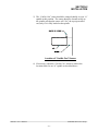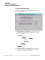
1
HSL-DC5
APM Decorator
High Speed Front End
User’s Manual
Systems Engineering Associates, Inc.
14989 West 69th Avenue
Arvada, Colorado 80007 U.S.A.
Telephone: (303) 421-0484
Fax: (303) 421-8108
www.sea-seg.com
03/2004
HSL-DC5
APM Decorator
High Speed Front End
User’s Manual
Copyright © 2001 Systems Engineering Associates, Inc.
All Rights Reserved!
Revised 15 March 2004
WARNING
To ensure the equipment described by this User Manual, as well as the equipment connected to
and used with it, operates satisfactorily and safely, all applicable local and national codes that
apply to installing and operating the equipment must be followed. This includes the National
Electric Code in the USA and other applicable legislation, regulations, and codes in practice
elsewhere. Since codes can vary geographically and can change with time, it is the user’s
responsibility to determine which standards and codes apply, and to comply with them.
FAILURE TO COMPLY WITH APPLICABLE CODES AND STANDARDS CAN RESULT IN
DAMAGE TO EQUIPMENT AND/OR SERIOUS INJURY TO PERSONNEL.
Persons supervising and performing installation or maintenance must be suitably qualified and
competent in these duties, and should carefully study this User Manual and any other manuals
referred to by it prior to installation and/or operation of the equipment.
The contents of the User Manual are believed to be correct at the time of printing; however, no
responsibility is assumed for inaccuracies. In the interests of a commitment to a policy of
continuous development and improvement, the manufacturer reserves the right to change the
specification of the product or it’s performance or the contents of the User Manual without notice.
Copyright © 2001 Systems Engineering Associates, Inc.
All Rights Reserved !
CONTENTS
1. General Description
1.1
1.2
1.3
1.4
1.5
1.6
1
Features
Functional Description
Mandrel Trip Control
Bad Can and Select-A-Can Pin Chain Blow-off
Alarm Detection
Data Collection
2. Installation
2.1
2.2
2.3
2.4
2.5
2.6
2.7
2.8
2.9
1
2
3
3
4
5
7
What’s Included
Power Required
Mounting and Wiring the HSL-DC5
Mounting the HSL-QCSTA
Mounting the RSV34-MS1 Resolver
Mounting the Mandrel #1 Mark I.D. Sensor
HSL-DC5 Software Installation
2.7.1 Windows Based Setup Program Installation
2.7.2 DOS Based Setup Program Installation
2.7.3 SYSdev Program Development Software
Installation
2.7.4 Application Program Installation
7
7
8
10
10
10
11
11
12
Modify Existing PLC Program
Tuning the HSL-DC5
2.9.1 Default Set-up Variables
2.9.2 Set Machine Zero
2.9.3 Verify Location of Can/No Can Sensor
2.9.4 Set Pin Chain Blow-off Timing “ON” Position
2.9.5 Set Can Gate Timing “ON” Position
2.9.6 Set Canfeed Enable Speed
2.9.7 Set Number of Pins to Pin Chain Blow-off Port
2.9.8 Set Spindle Trip Shift Offset
2.9.9 Set QC Blow-off Shift Offset
2.9.10 Set Number of Cans to Blow-off
2.9.11 Set Pin Chain Blow-off Solenoid
Response Times
2.9.12 Set O’Varnish Roll Speed Calibrate
14
17
18
19
20
22
23
23
23
24
24
25
2.10 M4508/P4500/D4591 Installation
2.10.1 M4508 Module Installation
2.10.2 P4500 Power Supply Installation
2.10.3 D4591 Keypad/Display Installation
2.10.4 Download HSLDC5 Program and
Set-up Data to M4508
HSL-DC5 User’s Manual
13
14
26
26
27
27
29
29
30
SYSTEMS Electronics Group
-i-
CONTENTS
3. Using the Keypad/Display
31
3.1
3.2
Default Screen
“Display Data” Key
3.2.1 Trips per Spindle Data
3.2.2 Current Shift Data
3.2.3 Last Shift Data
3.2.4 Display “Lifetime” Can Count
32
32
33
34
35
35
3.3
“Set-up” Key
3.3.1 Set Speed Parameters
3.3.2 Set Pneumatic Ductor Parameters
3.3.3 Set Pin Chain/QC Blow-off Parameters
3.3.4 Set Machine Timing
3.3.5 Zero Machine (set resolver offset)
3.3.6 Verify Can PRX Location/Timing
36
36
37
37
39
40
41
3.4
3.5
“QC Blow-off” Key
Set “Color Control” Key Passcode
41
41
4. APMDEC Windows Based
Set-up Program Reference
43
4.1
4.2
General Description
The File Menu
4.2.1 The Set-Up Data File
4.2.2 Upload (save) Data
4.2.3 Download Program
4.2.4 Download (restore) Data
4.2.5 Print Report
44
45
46
47
48
50
51
4.3
The Edit Menu
4.3.1 Enable Offline Editing
4.3.2 Setup Comm Port
4.3.3 Color Control Passcode
53
53
54
55
4.4
The View Menu
4.4.1 Target Board Interface
4.4.2 View Online Data
4.4.3 View Offline Data
56
56
58
58
4.5
The Window Menu
4.5.1 The Main Display Window
4.5.2 The Setup Parameters Window
4.5.3 The Shift Data Window
4.5.4 The Color Control Window
59
60
62
69
72
HSL-DC5 User’s Manual
SYSTEMS Electronics Group
- ii -
CONTENTS
5. HSLDC5 DOS Based
Set-up Program Reference
5.1
5.2
5.3
5.4
5.5
5.6
5.7
5.8
5.9
5.10
75
Set Speed Parameters
Set Ductor Parameters
Set Pin Chain/QC Blow-off Parameters
Adjusting Timing Set-points
Number of Trips per Spindle Data
Current Shift Data
Last Shift Data
Download Program to Module
Download (restore) Set-up Data to Module
Upload (save) Set-up Data from Module
76
77
79
82
83
84
85
86
87
88
6. Pneumatic Ductor Color Control
89
6.1
6.2
6.3
6.4
6.5
Features
Functional Description
Ductor Feedback
Operator Adjustable Parameters
Set-up Pneumatic Ductor Parameters
6.5.1 Default Ductor Configurations Settings
89
90
91
91
92
94
6.6
6.7
6.8
6.9
6.10
6.11
Manual/Off/Auto Control
Overview of Keys Relating to the Color Control
Recommended Procedure for Using the Color Control
Selecting the Label Number
Light/Dark Color Adjustment
Changeover Using an Existing Label
94
95
96
97
97
99
7. Recommended Spare Parts
101
LIST OF FIGURES
Recommended Panel Door Cut-out
Machine Zero Position
Location of “Can/No Can” Sensor
Location of Blow-off timing “ON” Position
Keypad/Display Legend
8
18
21
22
31
APPENDICES
Drawings
Appendix A
HSL-DC5 User’s Manual
SYSTEMS Electronics Group
- iii -
SECTION 1
GENERAL DESCRIPTION
This section describes the features of the M4508 APM Decorator
High Speed Logic Module. This includes the functional description,
alarms detected, etc.
________________________________________________________
1.1 FEATURES
•
Performs high speed control functions of the APM Decorator to
speeds in excess of 2400 CPM.
•
High speed front-end upgrade package which interfaces with
existing control system.
•
Accurate detection of misloaded cans and trip cam control
eliminates inside deco and varnish problems.
•
Accurate speed compensated single can (bad can) pin chain blowoff reduces scrap and eliminates silver cans down the line.
•
Single select-a-can QC pin chain blow-off allows operator to blow
off a can from a selected spindle (or blanket) to verify print
quality of each blanket with machine running at full production
speeds.
•
Can gate open/close control.
•
Alarm detection: infeed track jam, no can transfer (can on
mandrel), and timing signal fail detection.
•
Data Acquisition: Total number of good cans printed, total
number of blow-offs, trips per spindle, etc. (for both current shift
and last shift).
•
Built-in 2 Line X 40 character sealed display with 24 key
membrane keypad allows local viewing of collected data (can
count, blow-off count, trips per spindle) by operator and set-up of
all user variables (passcode protected or key switch enabled) by
authorized personnel.
•
Interfaces directly with machine mounted resolver, can/no can
sensor and all trip and blow-off solenoids.
HSL-DC5 User’s Manual
SYSTEMS Electronics Group
-1-
SECTION 1
GENERAL DESCRIPTION
•
Based on high performance M4508 PLC/PLS module which
allows easy trouble-shooting and user customization using
SYSdev (DOS-based) programming package.
•
Built-in PLS provides all machine timing, eliminating need for an
additional PLS.
________________________________________________________
1.2 FUNCTIONAL DESCRIPTION
The HSL-DC5 is an electronic upgrade for the APM
Decorator/Basecoater that detects miss-loaded cans, performs speed
compensated trip cam control, and single can (bad can) blow-off at
speeds in excess of 2400 CPM. In addition, a select-a-can pin chain
blow-off function is used to perform print quality verification of each
blanket. The control system interfaces directly to the machine
mounted resolver, can/no can sensor, trip and blow-off solenoids as
well as the host PLC via discrete DC I/O.
Alarm detection is provided including:
• Infeed Track Jam
• No Can Transfer (can on mandrel)
• Timing Signal Failure
Data collection (both for the current shift and last shift) includes:
• Total Good Can Count
• Blow-Off Counts
• Trips Per Spindle
The control system is not a dedicated “black box”, but is instead
implemented using the high performance SYSTEMS M4508
PLC/PLS module. This allows easy customization by either SEA or
the end user. The M4508 module is programmed using the DOSbased SYSdev programming package, which allows the module to be
programmed in any combination of Ladder or High-level (subset of
“C”), as well as perform on-line monitoring and trouble-shooting.
The M4508 module incorporates a built-in PLS which interfaces
directly with the machine-mounted resolver and provides all machine
timing, eliminating the need for an external PLS.
HSL-DC5 User’s Manual
SYSTEMS Electronics Group
-2-
SECTION 1
GENERAL DESCRIPTION
________________________________________________________
1.3 MANDREL TRIP CONTROL
Trip cam control at speeds in excess of 2400 CPM is incorporated in
the M4508. The appropriate trip cam is accurately extended for the
spindle of the miss-loaded can and retracted back prior to the spindle
following the miss-loaded can at all speeds. This reduces scrap by
providing an accurate single mandrel retract at all speeds. This
eliminates inside litho problems by assuring that the miss-loaded
spindle is completely skipped.
________________________________________________________
1.4 BAD CAN AND SELECT-A-CAN PIN CHAIN BLOW-OFF
Both the “Bad Can Pin Chain Blow-Off” and “Select-A-Can Pin
Chain Blow-Off” incorporate speed compensation to compensate for
the response time of the solenoid regardless of machine speed. This
allows accurate rejection of a single can from the pin chain at all
speeds. The bad can blow-off is activated automatically to reject
miss-loaded cans from the pin chain.
The “Select-A-Can” feature allows the user to dial in a mandrel
number, either at a remote PB station or from the Keypad/Display,
and blow-off one can printed on that mandrel. This provides a way to
verify the print quality of each mandrel. Two other “Select-A-Can
Blow-Off” modes are available. The “Consecutive Blanket” mode
blows off consecutive cans printed on each blanket, starting with
mandrel 1. The “Consecutive Spindle” mode blows off consecutive
cans printed on all mandrels, starting with mandrel 1.
The following variables can be set by the user for the “Bad Can” pin
chain blow-off:
• Number of shifts from machine to blow-off port (up to 999)
• Number of cans to blow-off for each bad can (one is normal, can
be up to 5).
• Both the “on” and “off” solenoid response time (used by the speed
compensation algorithm)
HSL-DC5 User’s Manual
SYSTEMS Electronics Group
-3-
SECTION 1
GENERAL DESCRIPTION
The following variables can be set by the user for the “Select-A-Can”
blow-off:
• Q.C. shift offset, this is used to match the actual mandrel number
to the selected mandrel number
• Both “on” and “off” solenoid response times
________________________________________________________
1.5 ALARM DETECTION
The following alarms are detected:
Infeed Track Jam: The infeed track jam alarm occurs when 7
consecutive empty mandrels are detected by the “Can/No Can
Sensor” after the can gate is opened.
No Can Transfer: The no can transfer alarm occurs when the “No
Can Transfer” sensor detects a can on the mandrel after the disk
transfer location.
Timing Signal Fail: The timing signal fail occurs when any of the
timing signals generated in the PLS section fail to change state while
the machine is running.
The “Encoded Alarm” outputs of the M4508 are as follows:
Alarm
None
Timing Signal Fail
No Can Transfer
Infeed Track Jam
HSL-DC5 User’s Manual
Bit 1
0
0
1
1
Bit 0
0
1
0
1
SYSTEMS Electronics Group
-4-
SECTION 1
GENERAL DESCRIPTION
________________________________________________________
1.6 DATA COLLECTION
The following data is collected for both the current shift and the
previous (last) shift:
•
•
•
•
•
•
•
Total Number of Good Cans Printed
Total Number of Cans Blown-Off
Total Number of Miss-Loaded Cans (bad cans)
Total Number of Restart Blow-Offs
Total Number of Manual Blow-Offs
Total Number of Select-A-Can QC Blow-Offs
Total Trips per Spindle (for each spindle)
This data can be viewed locally on the Keypad/Display or sent to the
host PLC via RS-232 communications (MODBUS or Allen-Bradley
DF1 protocols) using the optional S4516 communication board.
This information is updated (“Current” shift transferred to “Last”
shift) based on the change of state of the “End of Shift” input. This
can be activated on an 8 or 12-hour basis or alternatively based on
label run, depending on the user's preference.
A separate buffer is used to collect “Trips per Spindle” counts as a
diagnostic to aid in trouble-shooting a loading problem. Unlike the
shift data, these counts can be reset at will. This allows one to note an
abnormally high count on a specific mandrel.
The collected data is available via encoded “Blow-off Data” outputs
from the M4508 as follows:
Blow-off Data
None
Restart Blow-offs
QC Blow-offs
Manual Blow-offs
Bad Can Blow-offs
Good Cans
HSL-DC5 User’s Manual
Bit 2
0
0
0
0
1
1
Bit 1
0
0
1
1
0
0
Bit 0
0
1
0
1
0
1
SYSTEMS Electronics Group
-5-
SECTION 1
GENERAL DESCRIPTION
(This Page Intentionally Left Blank)
HSL-DC5 User’s Manual
SYSTEMS Electronics Group
-6-
SECTION 2
INSTALLATION
The standard HSL-DC5 control system is provided for back-panel
mounting inside the existing control cabinet.
________________________________________________________
2.1 WHAT’S INCLUDED
Verify that the following items are included when unpacking the
HSL-DC5:
1ea.
1ea.
1ea.
1ea.
1ea.
1ea.
M4508 PLC/PLS module
P4500 Power Supply
D4591 Display with ribbon cable for mounting in the
existing control cabinet door
HSL-DC5 User's Manual
M4500 User’s Manual
HSL-DC5 Program Disk
The following items are optional items and can be purchased
separately as required or desired:
1ea. HSL-QCSTA Remote Select-A-Can PB station
1ea. RSV34-MS1 Resolver
1ea. RSV-RSCBLE-XX Resolver Cable
________________________________________________________
2.2 POWER REQUIRED
The HSL-DC5 is powered from 115VAC/230VAC 50/60HZ and
+24VDC. The 115VAC/230VAC is used to power the M4508
module while the +24VDC is used to power the +24VDC I/O
(sensors, trip and blow-off solenoids).
Note: +24VDC solenoids must be used for all trip and blow-off
solenoids. These provide a more consistent and repeatable response
time than 115VAC solenoids.
If +24VDC solenoids were used in the existing system, the +24VDC
current required by the HSL-DC5 is no more than the existing
systems +24VDC current requirement, therefore the existing +24VDC
power supply should be adequate.
HSL-DC5 User’s Manual
SYSTEMS Electronics Group
-7-
SECTION 2
INSTALLATION
________________________________________________________
2.3 MOUNTING AND WIRING THE HSL-DC5
Mount the back-panel in the existing control cabinet.
Referring to the figure below, create a cut-out in the existing control
cabinet door and mount the D4591 Keypad/Display.
D4591 Recommended Panel Door Cut-out
Note: The D4591 must be located within 6 feet of the M4508 module
to avoid EMI pick-up on the display ribbon cable. Connect the ribbon
cable from the M4508 module to the D4591 module.
HSL-DC5 User’s Manual
SYSTEMS Electronics Group
-8-
SECTION 2
INSTALLATION
Referring to the electrical control schematic at the back of this
manual, wire the HSL-DC5 to the existing control system as follows:
Note: Keep all +24VDC wiring, resolver cable, and sensor cable
wiring away from high voltage wiring. Wire the machine-mounted
resolver directly to the 8-pin resolver input connector of the M4508.
1) Incoming Power: 115VAC-230VAC to FU1, neutral to 900 and
ground to GND. Logic power (+24VDC) to 501 and common to
500. Control power (+24VDC) to 601 and common to 600.
2) Interlocks from existing control system (terminals I12 through I17
& I42).
3) Interlocks to existing control system (terminals O10 through
O19).
4) Module fault interlock (FLT; +24VDC sink output)
5) Can Gate, Bad Can Blow-off and Q.C. Can Blow-off solenoids
(FU2, FU3 & FU4)
6) Trip Cam “ON” and “off” solenoids (FU5 through FU10)
7) Ductor solenoids (FU11 through FU18)
8) Can/No Can sensor, Mandrel No.1 Mark sensor, Can on Mandrel
sensor (terminals I09, I10 & I11) and Ductor Feedback sensors
(terminals I40 through I47) using three conductor shielded cables.
The shields of the sensor cables should be tied to earth ground at a
terminal inside the existing control cabinet and left floating at the
sensors.
9) Set-Up Enable key switch (if desired) to allow entry to set-up
variables through Keypad/Display
10) Resolver cable from resolver (or existing PLS) to 8-pin resolver
input connector on the M4508 using a three pair, two conductor
shielded cable. The shield of the resolver cable should be tied to
the “SHLD” terminal of the M4508 resolver input connector.
Make sure the resolver cable shield is left floating at the resolver.
HSL-DC5 User’s Manual
SYSTEMS Electronics Group
-9-
SECTION 2
INSTALLATION
________________________________________________________
2.4 MOUNTING THE HSL-QCSTA
The HSL-QCSTA is used to blow-off a can from a selected spindle
(or blanket) from the pin chain for quality verification. If the optional
HSL-QCSTA remote select-a-can PB station was purchased, mount it
in the vicinity of the pin chain QC blow-off port in a convenient
location for the operator. Wire the HSL-QCSTA to the HSL-DC5
referring to the electrical control schematic at the back of this manual.
________________________________________________________
2.5 MOUNTING THE RSV34-MS1 RESOLVER
The HSL-DC5 is designed to interface to a resolver (not encoder) for
machine timing. If the machine is not already equipped with a
resolver, then the existing encoder will have to be removed and a
resolver mounted in its place.
Note: The resolver must make 1 revolution per 2 spindles (interposer
trip), 1 revolution per 3 spindles (rotary trip).
Route the resolver cable in a separate conduit, away from all other
high voltage and control wiring. Wire the cable directly to the 8-pin
resolver connector on the M4508 (see section 2.3).
________________________________________________________
2.6 MOUNTING THE MANDREL #1 MARK I.D. SENSOR
If the machine has not been provided with a spindle #1 I.D. sensor,
then one will have to be mounted. This sensor is used to determine
which spindle is the #1 spindle for both the QC select-a-can blow-off
and the trips per spindle count. This must see a target once every
revolution of the spindle wheel (once every 24 spindles). Any nondiscriminating 10-30VDC proximity sensor can be used and can be
mounted anywhere around the periphery of the spindle wheel. The
target should be either a large steel bolt head or 1” by 1” square steel
target mounted on the spindle wheel in the vicinity of spindle #1.
HSL-DC5 User’s Manual
SYSTEMS Electronics Group
- 10 -
SECTION 2
INSTALLATION
________________________________________________________
2.7 HSL-DC5 SOFTWARE INSTALLATION
Follow the steps below to install either the Windows or DOS based
setup programs and PLC application program on a PC used to support
the HSL-DC5 control system.
________________________________________________________
2.7.1 WINDOWS BASED SETUP PROGRAM INSTALLATION
The APMDEC setup program is compatible with Windows
95/98/ME/2000/XP operating systems and is used to:
• Setup (tune) the user adjustable variables
• Adjust the timing channel set-points
• Download the application program to the M4508 module
• Download (restore) or upload (save) the user setup variables from
the M4508
• View “Shift” and “Trips per Spindle” data
To install the set-up software, perform the following steps:
1) Insert the HSL-DC5 CD into the drive
2) From the Windows desktop, “Click” Start and then select run.
3) From the “Run” dialog box, “Click” the Browse button.
4) Select the drive with HSL-DC5 CD. Select the “setup.exe” file
and “Click” Open and then Ok.
5) This will initiate the installation process. Follow the instructions
that appear on the screen to complete the installation process. The
APMDEC setup program can be executed from the “Systems”
folder located in Programs.
HSL-DC5 User’s Manual
SYSTEMS Electronics Group
- 11 -
SECTION 2
INSTALLATION
________________________________________________________
2.7.2 DOS BASED SETUP PROGRAM INSTALLATION
The HSLDC5 set-up software is used to:
• Setup (tune) the user adjustable variables
• Adjust the timing channel set-points
• Download the application program to the M4508 module
• Download (restore) or upload (save) the user setup variables from
the M4508 to disk
• View “Shift” and “Trips per Spindle” data.
To install the DOS based set-up software perform the following steps:
1) Create a directory off the root for each decorator. These will be
used to store the “HSLDC5.EXE” setup program and set-up data
for each decorator.
Create a directory for each machine:
HSLDEC1 (line 1 Decorator)
HSLDEC2 (line 2 Decorator)
HSLDEC3 (line 3 Decorator)
etc.
1) Install the “PROGRAMS” disk into the drive. For each
“HSLDEC” directory you created, at a DOS prompt:
• Switch to that directory
• Install the “HSLDC5” set-up program by typing the following
(Line 1 decorator is shown):
CD \HSLDEC1<ENTER>
A:INSTALL<ENTER>
HSL-DC5 User’s Manual
SYSTEMS Electronics Group
- 12 -
SECTION 2
INSTALLATION
3) Add each decorator's set-up program to your computer's menu
software by creating a selection for each decorator called:
• “SET-UP DECO LINE1” for the line #1 decorator
• “SET-UP DECO LINE2” for the line #2 decorator
etc..
The DOS commands executed for these selections should be (Line
1 decorator is shown):
For the “SET-UP DECO LINE1” selection:
CD \HSLDEC1
HSLDC5 HSLDC5
CD \
4) To execute the respective decorator's set-up program, simply
select the corresponding “SET-UP DECO LINE” selection from
the menu software's menu.
5) Alternatively, a “PIF” file for each HSLDC5.EXE could be setup
on the Windows desktop.
________________________________________________________
2.7.3 SYSDEV PROGRAM DEVELOPMENT SOFTWARE
INSTALLATION
The SYSdev Program Development software is used to perform online trouble-shooting and program modifications to the HSL-DC5. If
SYSdev was purchased with the HSL-DC5 package and is not already
installed on the your computer, install SYSdev onto the hard drive of
your computer following the steps in outlined in the SYSdev Program
Development manual.
HSL-DC5 User’s Manual
SYSTEMS Electronics Group
- 13 -
SECTION 2
INSTALLATION
________________________________________________________
2.7.4 APPLICATION PROGRAM INSTALLATION
The application program is a SYSdev based program, loaded into the
M4508 module and performs the HSL-DC5 logic. The program is
written in a combination of Ladder logic and High-level. If the user
desires to make program changes or perform on-line monitoring of
the program execution the files, which constitute the HSLDC5
program, will have to be loaded onto the hard drive of the PC used to
support the system. The SYSdev Program Development Software will
also have to be loaded on the PC. To install this program perform the
following:
1) Install the “PROGRAMS” disk into the drive.
2) For each of the “HSLDEC” directories (created in section 2.7.2),
copy all the files from the disk to each of these subdirectories.
________________________________________________________
2.8 MODIFY EXISTING PLC PROGRAM
Modify the existing control system PLC program to interface with the
HSM-DC5 by incorporating the following into the existing PLC
ladder logic:
1) The HSM-DC5 now controls:
• The Can Gate Solenoid
• Pin Chain Blow-Off Solenoids
• Trip Cam Solenoids
• Ductor Solenoids
If the existing host PLC was controlling these functions, this logic
can optionally be removed from the existing host PLC if desired.
In most cases this logic can be left in the program as connecting
the respective solenoids to the HSM-DC5 will effectively defeat
the logic.
2) The “Test Mode” can be an output from the PLC or from a push
button or selector switch. The cans will then be blown off at the
“Bad Can” pin chain blow-off port as long as this input is “ON”.
HSL-DC5 User’s Manual
SYSTEMS Electronics Group
- 14 -
SECTION 2
INSTALLATION
3) The “End of Shift” can be an output from the PLC or from a push
button. When the “End of Shift” input goes “ON” the current
shift data is transferred to the last shift and all data registers for
the current shift, as well as the trips per spindle, will be reset to
zero.
4) Add the “Can Feed Enable” output to the PLC logic. When
turned “on” while running, the infeed is timed “open” with the can
feed timing signal. When turned “off” while running, the infeed is
timed “closed” with the can feed timing signal. When the
machine is stopped, turning this input “on” and “off” will
respectively “open” and “close” the can stop.
5) Add the “Main Drive On” output to the PLC logic. This should
be “on” when the drive is enabled (running) and should be “off”
when the drive is disabled (this includes auto stop conditions).
This is true for jog modes as well.
6) Add the “Alarm Reset” output. This signal should be “on” as
long as the system reset push-button is depressed.
7) Add the “Pin Chain Manual Blow-off” output to the PLC logic.
When “on”, the bad can pin chain blow-off is “on”. When “off”,
the pin chain blow-off functions normally blowing off detected
bad cans, restart cans, etc.
8) Add the “PLC Clock” (timing channel CH06) input to the PLC
logic. This is a general purpose PLC clock timing signal, pulsed
once per can.
9) Add the “Blow-off Data Clock” (timing channel CH07) input to
the PLC logic. This is used to clock the blow-off data bits (0, 1
and 2). Use the leading edge of this signal to increment the PLC
blow-off data counters. The blow-off data is encoded into a 3-bit
binary code according to the following chart.
None
Restart Blow-off
Q.C. Blow-off
Manual Blow-off
Bad Can Blow-off
Good Can
HSL-DC5 User’s Manual
BLOWOFF 2 BLOWOFF 1 BLOWOFF 0
0
0
0
0
0
1
0
1
0
0
1
1
1
0
0
1
0
1
SYSTEMS Electronics Group
- 15 -
SECTION 2
INSTALLATION
10) The following alarms are available to the host PLC via the
discrete encoded alarm bits according to the following chart.
ALARM BIT 1 ALARM BIT 0
Timing Signal Fail
0
1
No Can Transfer
1
0
Infeed Track Jam
1
1
11) Add the “Canfeed Enable Speed” into the PLC logic. The canfeed
enable speed comes “ON” whenever the speed of the machine is
within the canfeed enable window. Use this signal to control the
canfeed enable whenever this signal is “ON”.
12) Add the “Ductors Feedback Fault” into the PLC logic. If a ductor
is not detected as cycling properly, the “Ductor Feedback Fault” is
energized, indicating a problem with the ductor cycling control. If
the ductor feedback sensors are used, enable the particular stations
that have feedback. If the ductor feedback is not used, disable all
stations that do not have feedback.
If a “Ductor Feedback Fault” does occur, the ductors should be
manually activated to verify proper cycling operation, as well as,
the sensor for proper feedback operation. The feedback sensor
should be set such that it is only “ON” when the ductor is in
contact with the fountain roll.
13) Add the “Ductors Auto On” into the PLC logic. This input should
be “ON” whenever cans are feeding into the decorator.
HSL-DC5 User’s Manual
SYSTEMS Electronics Group
- 16 -
SECTION 2
INSTALLATION
________________________________________________________
2.9 TUNING THE HSL-DC5
The HSL-DC5 is shipped from the factory with the application
program loaded in the PLC. In most cases, the default variables and
timing signals will have to be altered to tune the HSL-DC5 to the
actual decorator it is controlling.
Once the system is installed and powered back up, perform the
following to set-up and tune the HSL-DC5. The set-up is performed
using either the Keypad/Display or a PC running the set-up program.
See section 3 of this manual for a description of the Keypad
commands and menu displays of the Keypad/Display. See sections 4
and 5 for a description of menus and variables and how to use the setup programs.
HSL-DC5 User’s Manual
SYSTEMS Electronics Group
- 17 -
SECTION 2
INSTALLATION
________________________________________________________
2.9.1 DEFAULT SET-UP VARIABLES
As shipped, the user variables for the M4508 are set the following
defaults:
Speed Parameters:
Canfeed Enable - Low Speed
Canfeed Enable - High Speed
O’Varnish Roll Speed Calibrate
: 600
: 1000
: 380
Pneumatic Ductor Parameters:
: 500
Maximum Cycle Duration (0.1 cans)
Maximum “On” Duration (0.1 cans)
: 200
Response Time Compensation (msec)
: 25
Color Gain (CG-100% per 2000cpm)
: 100%
Feedback Enabled
: 1N, 2N, 3N, 4N, 5N, 6N, 7N, 8N
Bad Can (pin chain) Blowoff:
# of cans to blowoff from infeed open
# of cans to blowoff from print at restart
# of cans to blowoff from varnish at restart
# of bad cans to blowoff for misload
# of pins to pin chain blowoff port
Blowoff solenoid “on” response time (msec)
Blowoff solenoid “off” response time (msec)
: 012
: 000
: 000
: 001
: 032
: 015
: 028
QC Can (select-a-can) Blowoff:
Blowoff solenoid “on” response time (msec)
Blowoff solenoid “off” response time (msec)
QC can blowoff port shift offset
: 015
: 028
: 001
Spindle Trip Offset
: 000
Timing Setpoints:
Bad Can blowoff “ON” position
Q.C. blowoff timing “ON” position
Can Gate timing “ON” position
: 180°
: 185°
: 0°
HSL-DC5 User’s Manual
SYSTEMS Electronics Group
- 18 -
SECTION 2
INSTALLATION
________________________________________________________
2.9.2 SET MACHINE ZERO
To zero the machine (set resolver offset) perform the following:
1) Enter the “Set-Up” menu by pressing the “SET-UP” key of the
Keypad/Display.
2) Select “6: VERIFY CAN PRX1 LOCATION/TIMING” and
observe the “ACTUAL ABSOLUTE POS:” field. Verify that as
the machine is rotated forward (either jogged or barred) that the
position increases linearly from 0 through 1079 for “Rotary Trip”
Machines or 0 through 719 for interposer trip machines. If not,
swap the S1 and S3 leads of the resolver at the M4508 resolver
connector. Then verify that the position then indeed does increase
with forward movement. Press <ESC> to return to the primary
set-up menu.
3) Position the machine at machine zero (“A” trip cam follower just
past “A” trip cam, (see figure below).
4) Auto zero the resolver by selecting “5: ZERO MACHINE” from
the primary set-up menu of the Keypad/Display. Enter “0” to zero
the resolver. The “VERIFY CAN PRX” menu will be displayed,
now showing the “ACTUAL ABSOLUTE POS:” at zero.
5) The M4508 will calculate the actual offset value required to make
this the 000 position and will display this number in the offset
field.
HSL-DC5 User’s Manual
SYSTEMS Electronics Group
- 19 -
SECTION 2
INSTALLATION
6) Return to the primary set-up menu by pressing the <ESC> key.
Return to the default screen by pressing the <ESC> key again.
________________________________________________________
2.9.3 VERIFY LOCATION OF CAN/NO CAN SENSOR
Verify the location of the “Can/No Can” sensor by placing a can on
an “A” spindle and performing the following:
1) Enter the “Set-Up” menu by pressing the “SET-UP” key of the
Keypad/Display.
2) Select “6 VERIFY CAN PRX1 LOCATION/TIMING”.
3) Locate the machine with an “A” spindle approximately under the
“Can/No Can” sensor. The “Can/No Can” sensor is located
approximately at the “One O’clock” position of the spindle wheel
(see sheet 2 of the electrical timing procedure drawing at the back
of this manual).
4) Locate the machine to the exact location, defined as follows:
Interposer Trip Type Machines: Locate the machine at
exactly 630 degrees as displayed in the “Actual Absolute POS”
field of the Keypad/Display.
Rotary Trip Type Machines: Locate the machine at exactly
270 degrees as displayed in the “Actual Absolute POS” field of
the Keypad/Display.
HSL-DC5 User’s Manual
SYSTEMS Electronics Group
- 20 -
SECTION 2
INSTALLATION
5) The “Can/No Can” sensor should be centered radially over an “A”
spindle at this position. The sensor should be located axially on
the spindle such that the sensor will “See” the top (open end of
can) only if it is fully loaded on the spindle.
Location of “Can/No Can” Sensor
6) If necessary, adjust the “Can/No Can” sensor to achieve the
location relative to an “A” spindle as described above.
HSL-DC5 User’s Manual
SYSTEMS Electronics Group
- 21 -
SECTION 2
INSTALLATION
________________________________________________________
2.9.4 SET PIN CHAIN BLOW-OFF TIMING “ON” POSITION
This timing signal should just turn “ON” when the pin chain blow-off
port is centered between pins on the pin chain. To set either the “Bad
Can Blow-off” or “Q.C. Blow-off” timing “ON” position, perform the
following:
1) Locate the machine with the blow-off solenoid centered between
pins on the pin chain (as shown below).
“ON” Position of Pin Chain Blow-off Solenoid
2) This is the “ON” position for the blow-off solenoid. This position
will be different for the “Bad Can Blow-off” and “Q.C. Blow-off”
solenoids.
HSL-DC5 User’s Manual
SYSTEMS Electronics Group
- 22 -
SECTION 2
INSTALLATION
________________________________________________________
2.9.5 SET CAN GATE TIMING “ON” POSITION
This signal is used to open and close the can gate. Adjust the “ON”
position for proper can gate operation.
________________________________________________________
2.9.6 SET CANFEED ENABLE SPEED
Set the “Canfeed Enable Low Speed” and “Canfeed enable High
Speed” in conjunction with one another to define a window within
which the can gate can be opened or closed. This allows the flow of
cans to be controlled whenever the machine speed is inside this
window. When the machine goes to a stand-by condition, the speed
of the machine will need to be decreased inside this window for the
can gate solenoid to be deactivated. The M4508 will
activate/deactivate the can gate solenoid on the “Can Gate Timing
ON” signal.
________________________________________________________
2.9.7 SET NUMBER OF PINS TO PIN CHAIN BLOWOFF
PORT
Set the “# of pins to pin chain blowoff port” by counting the number
of pins from the spindle wheel to disc transfer location to the bad can
pin chain blowoff port. The number entered is the number counted
minus 2 (this is just an approximation).
Set the “# of bad cans to blow-off for each misload” equal to one.
Run the machine at low speed with cans and verify that for each
misload, the one bad can is blown off. If the bad can is not blown off
then adjust the “# of pins to pin chain blow-off port” accordingly until
the misloaded can is blown off.
Note: On this system, only one can is normally blown off for each
misload on a particular mandrel. However, the end user may select to
blow-off up to five cans to get rid of the excess ink on a particular
blanket. The chain take-up must be after the bad can pin chain blowoff. If the take-up is before the port, the relative position of the port
to the blow-off timing will vary as the take-up moves, causing partial
blow-offs to occur.
HSL-DC5 User’s Manual
SYSTEMS Electronics Group
- 23 -
SECTION 2
INSTALLATION
________________________________________________________
2.9.8 SET SPINDLE TRIP SHIFT OFFSET
Set the “Spindle Trip Shift Offset” as follows:
1) Initially set the “Spindle Trip Offset” to zero.
2) Wrap a piece of tape around spindle #1 such that cans will not
load on this spindle.
3) Run the machine very slowly with the can gate open and verify
that indeed cans do not load on spindle #1 and that the #1 spindle
is tripped.
4) Observe the trips per spindle data and determine which spindle
number is being incremented every time the #1 spindle trips. The
spindle number that should be incrementing is spindle #1. If it is
not, subtract 1 from the spindle number that is being incremented
and enter this value as the spindle trip offset (this variable must be
a number between 0 and 23 or 35).
5) Now verify that the spindle #1 count is incremented every time
the #1 spindle trips. If it still increments another spindle number
other than #1, continue adjusting the “Spindle Trip Offset” until it
does, then stop the machine and remove the tape from spindle #1.
________________________________________________________
2.9.9 SET QC BLOW-OFF OFFSET
Set the “QC Can Blowoff Port Shift Offset” as follows:
1) Dial in spindle #1 on the select-a-can thumb wheel switch.
2) Run the machine slowly and mark cans printed on spindle #1 so
they can be identified while they are on the chain.
3) Press the select-a-can push-button and observe the can blown off
with the location of a can printed on spindle #1.
4) Add the number of cans difference between the can actually
blown off and the can printed on spindle number one to the “QC
can blowoff port shift offset”.
HSL-DC5 User’s Manual
SYSTEMS Electronics Group
- 24 -
SECTION 2
INSTALLATION
Note: This variable must be a number between 1 and 24 or 36, as
there is always a can printed on spindle #1 every 24 or 36 cans. Once
set-up, verify that a can from spindle #1 is blown off when 1 is dialed
in on the thumb wheel and the select-a-can push-button is pressed.
________________________________________________________
2.9.10 SET NUMBER OF CANS TO BLOW-OFF
Set the number of cans to blow-off as desired.
# Cans to Blow-Off for Each Mis-Load: This is the number of
cans blown off at the pin chain port when a mis-loaded can is detected
(typically set at 1 can). Any additional cans entered, will be blown
off every 12th can later (cans printed on the same blanket).
# Cans to Blow-off at Infeed Open: This is the number of cans
blown off when the infeed is first opened. Valid range: 0 to 99.
# Cans to Blow-off from Print at Restart: This is the number of
cans blown off from the print station when the machine is restarted.
Valid range: 0 to 99.
# Cans to Blow-off from Varnish at Restart: This is the number
of cans blown off from the varnish station when the machine is
restarted. Valid range: 0 to 99.
HSL-DC5 User’s Manual
SYSTEMS Electronics Group
- 25 -
SECTION 2
INSTALLATION
________________________________________________________
2.9.11 SET PIN CHAIN BLOW-OFF SOLENOID RESPONSE
TIMES
Pin Chain (bad can and QC) Blow-off Solenoid “ON”
Response Time (msec): This is the time used as the “ON”
response time of the pin chain blow-off port (time from solenoid
actuation to first air out port) in milliseconds. The M4508 will
activate the solenoid this amount of time ahead of the Pin Chain
blow-off “ON” position (usually set at 15 to 20 milliseconds). Valid
range: 5 to 60 msec.
Pin Chain (bad can and QC) Blow-off Solenoid “off”
Response Time (msec): This is the time used as the “off”
response time of the pin chain blow-off port (time from solenoid “off”
actuation to air stopping at port) in milliseconds. The M4508 will
activate the solenoid “off” this amount of time ahead of the Pin Chain
blow-off “ON” position (usually set at 15 to 20 milliseconds for
double acting solenoids and set at 25 to 30 milliseconds for single
acting solenoids). Valid range: 5 to 60 msec.
________________________________________________________
2.9.12 SET O’VARNISH ROLL SPEED CALIBRATE
The O’Varnish drive speed input is a 0-10VDC signal from the
O’Varnish drive (if available). The roll speed calibrate is used to
scale this signal to display the “O’Varnish RPM”. The number
entered should equal the O’Varnish roll speed when the drive is at full
speed (input = 10VDC).
THE MACHINE IS NOW SET-UP AND READY TO RUN!
HSL-DC5 User’s Manual
SYSTEMS Electronics Group
- 26 -
SECTION 2
INSTALLATION
________________________________________________________
2.10 M4508/P4500/D4591 INSTALLATION
The following is provided only as a reference. These steps are
performed by the factory prior to shipping the HSL-DC5. These steps
need only be performed in the event either the M4508 module, P4500
power supply, or D4591 display need to be replaced. Refer to the
M4500 User’s Manual for general details on installing the M4508,
P4500, and D4591.
________________________________________________________
2.10.1 M4508 MODULE INSTALLATION
To install the M4508 module, perform the following:
1) Remove the cover from the M4508 chassis (retained with three
captive screws on the lower front of the cover and two captive
screws on each side of the M4508 chassis).
2) Install S4563 (SLOT0-0): Set the slot address dip switches (SW1)
on the S4563 to the following positions (slot0):
S4563:
SW1 switch1 = "OFF"
SW1 switch2 = "OFF"
Install the S4563 in Slot0-0 (furthest left slot) of the M4508
chassis.
3) Install S4573 (SLOT0-1): Set the slot address dip switches (SW1)
on the S4573 to the following positions (slot1):
S4573:
SW1 switch1 = "ON"
SW1 switch2 = "OFF"
Install the S4573 in Slot0-1 (slot next to S4563) of the M4508
chassis.
HSL-DC5 User’s Manual
SYSTEMS Electronics Group
- 27 -
SECTION 2
INSTALLATION
4) Install S4573 (SLOT0-2): Set the slot address dip switches (SW1)
on the S4573 to the following positions (slot2):
S4573:
SW1 switch1 = "OFF"
SW1 switch2 = "ON"
Install the S4573 in Slot0-2 (slot next to S4573) of the M4508
chassis.
5) Install S4573 (SLOT0-3): Set the slot address dip switches (SW1)
on the S4573 to the following positions (slot3):
S4573:
SW1 switch1 = "ON"
SW1 switch2 = "ON"
Install the S4573 in Slot0-3 (slot next to S4573) of the M4508
chassis.
6) Install the cover back over the M4508, making sure all the board
connectors protrude the slots in the cover. Tighten the three
captive screws on the lower front of the cover and the two captive
screws on each side of the M4508 chassis.
7) Connect the display ribbon cable to the connector on the back of
the M4508 (the connector on the cable is polarized and should
mate with the connector on the M4508 only one way).
8) Mount the M4508 chassis to the HSL-DC5 back panel using four
8-32 screws.
9) With power to the P4500 "off", install the P4500 power supply
cable to the +5/C/+12/C/-12 connector on the M4508 (the
connector on the cable is polarized and should mate with the
connector on the M4508 only one way).
10) Install the respective field wiring arms on all the I/O boards of the
M4508 (I/O slots0 thru 3, resolver connector, and IN0/IN1
connector). Make sure all field wiring connectors are fully mated
in the M4508.
HSL-DC5 User’s Manual
SYSTEMS Electronics Group
- 28 -
SECTION 2
INSTALLATION
________________________________________________________
2.10.2 P4500 POWER SUPPLY INSTALLATION
To install the P4500, perform the following steps:
1) Mount the P4500 to the HSL-DC5 in the mounting holes next to
the M4508 (left side) using two 8-32 screws.
2) With power to the P4500 "off", install the P4500 power supply
cable to the +5/C/+12/C/-12 connector on the M4508 (the
connector on the cable is polarized and should mate with the
connector on the M4508 only one way).
________________________________________________________
2.10.3 D4591 KEYPAD/DISPLAY INSTALLATION
To install the D4591, perform the following steps:
1) With the gasket installed on the mounting studs of the D4591,
install the D4591 in the cut-out in the user's existing control
cabinet. Secure the display to the enclosure using 7ea. 8-32 nuts
and external lock washers.
2) Connect the display ribbon cable to the connector on the lower
back of the display (the connector on the cable is polarized and
should mate with connector on the M4508 only one way).
HSL-DC5 User’s Manual
SYSTEMS Electronics Group
- 29 -
SECTION 2
INSTALLATION
________________________________________________________
2.10.4 DOWNLOAD HSLDC5 PROGRAM AND SET-UP
DATA TO M4508
Once the M4508/P4500/D4591 are installed, perform the following to
download the HSLDC5 application program to the M4508 as well as
download the previously saved set-up data and timing channel setpoints:
1) Power up the M4508 and the PC used to interface with the HSLDC5.
2) Connect an RS-232 cable from the computer COM port to the
"PROG" port on the M4508.
3) Initiate the respective setup program (APMDEC for Windows
systems, HSLDC5.exe for DOS systems).
4) Download the HSLDC5 application program to the M4508. See
section 4.2.3 for Windows based systems, see section 5.8 for
DOS.
6) Download the previously saved set-up data to the M4508. See
section 4.2.4 for Windows based systems, section 5.9 for DOS.
7) The M4508 is now ready to run, loaded with HSLDC5 application
program, timing set-points, and set-up data.
Note: Double check the machine zero position and re-zero the
resolver if necessary, prior to running the machine.
HSL-DC5 User’s Manual
SYSTEMS Electronics Group
- 30 -
SECTION 3
USING THE KEYPAD/DISPLAY
The D4591 Keypad/Display contains 24 keys consisting of data
display commands, set-up commands, and a numeric keypad. The
display is a 2 line by 40 character back-lit LCD display which
displays the selected data and set-up menus. The Keypad/Display can
be used to view data, adjust the timing and all set-up parameters,
activate the select-a-can QC blow-off and adjust the pneumatic ductor
color control parameters.
The Keypad/Display allows the following to be viewed or adjusted:
1) Set Speed Parameters
2) Set Pneumatic Ductor Parameters
3) Set Pin Chain/QC Blow-off Parameters
4) Set Machine Timing
5) Set Machine Zero
6) Verify Location of Can/No Can Sensor
7) View the Number of Trips per Spindle
8) View the Current Shift Data
9) View the Last Shift Data
10) View Lifetime Can Count
11) Activate the select-a-can QC blow-off
12) Adjust the Color Control Parameters
The definitions of the keypad commands and menus are described in
the following sections.
HSL-DC5 User’s Manual
SYSTEMS Electronics Group
- 31 -
SECTION 3
USING THE KEYPAD/DISPLAY
Note: For virtually all the menus, the “NEXT” and “PREV” keys
can be used to advance to the next or previous parameter respectively.
To change the currently displayed parameter, simply enter the new
value on the numeric keypad and press <ENTER>. The value will be
entered and the next parameter will automatically be displayed.
When the last parameter in a section is entered, the primary set-up
menu is again displayed. Pressing <ESC> at anytime will exit back to
the primary set-up menu.
________________________________________________________
3.1 DEFAULT SCREEN
The default screen (displayed when no other commands are active)
contains the following data:
MACHINE CPM:0000
GOOD CANS:0
O’VARNISH RPM:000
BLOWOFFS:0
“Machine Speed” is the current speed of the decorator. “O’Varnish
RPM” is the current speed of the varnish unit. “Good Cans” field is
the total number of good cans printed so far into the current shift, and
the “Blow-offs” field is the total number of cans blown-off the
machine (scrap) so far into the current shift. This display effectively
replaces a speed meter, and two can counters. This screen is always
returned to when no commands are active.
________________________________________________________
3.2 “DISPLAY DATA” KEY
This selection is used to invoke the primary display data menu. This
consists of the following selections:
1: DISPLAY TRIPS PER SPINDLE DATA
2: DISPLAY CURRENT SHIFT DATA
3: DISPLAY LAST SHIFT DATA
4: DISPLAY LIFETIME CAN COUNT
When selected, each of the above selections will bring up a sub-menu
with the corresponding data. The following sections describe these
sub-menus and the definitions of the corresponding data. To select
the respective sub-menu, simply press the corresponding numeric key
(1 through 4).
HSL-DC5 User’s Manual
SYSTEMS Electronics Group
- 32 -
SECTION 3
USING THE KEYPAD/DISPLAY
________________________________________________________
3.2.1 TRIPS PER SPINDLE DATA
The Number of trips per spindle menu is provided to aid in the
trouble-shooting of a loading problem with a spindle or spindles. The
total number of trips for each spindle since the last reset or end of
shift is displayed. The operator can reset these counts at any time to
aid in the trouble-shooting process. The data can be viewed simply
by pressing this key. The display shows a series of screens each with
four spindles from 1 through 24 or 36 as shown below:
-- TRIPS (MIS-LOADS) PER SPINDLE -1:xxxx
2:xxxx
3:xxxx
4:xxxx
Where the numbers 1 through 4 are the first 4 spindles and the “xxxx”
would be the actual counts for the respective spindles. Screens for the
rest of the spindles are shown in this fashion, each for a time delay of
10 seconds.
The final screen prompts the user to reset the counts by pressing “0”
or press “ESC” to return to the main menu. This provides the
operator with the opportunity to reset the counts if desired.
The “ESC” key can also be used at any time to abort the trips per
spindle data display and return to the default screen.
HSL-DC5 User’s Manual
SYSTEMS Electronics Group
- 33 -
SECTION 3
USING THE KEYPAD/DISPLAY
________________________________________________________
3.2.2 CURRENT SHIFT DATA
The “Current Shift” data is the totals so far into the current shift. The
data is transferred to the “Last shift” when the end of shift input
transfers from a “0” to a “1”. This can be at the end of either an 8 or
12 hour shift or alternatively could be done at label changes such that
the data collected would be for label runs rather than complete shifts.
This data cannot be reset by the operator, only at the end of shift
transition. Note: The Current shift “Good Cans” and “Blow-offs” is
displayed as part of the default screen (see section 3.1 – Default
Screen, Using the Keypad/Display).
The Current Shift data is defined as follows:
Good Cans: This is the total number of good cans printed so far into
the shift. This is essentially a can counter.
Blow-offs: This is the total number of cans blown-off the machine.
This includes all types of blow-offs: cans blown-off for every misloaded can, infeed open blow-offs, restart blow-offs, manual blowoffs, select-a-can QC blow-offs, etc.
Mis-loads: This is the total number of mis-loaded cans (trips).
These would be the actual number of damaged cans that did not load
properly on the machine. This gives an indication of conveying/can
handling problems.
Restart Blow-offs: This is the total number of cans blown off when
the infeed opened and from the print station and varnish station at
machine restart.
Manual Blow-offs: This is the total number of cans blown-off by
the operator using the Manual Blow-off PB or selector switch.
QC Blow-offs: This is the total number of cans blown-off by the
operator with the Select-A-Can QC station or QC Blow-off key on the
D4591 keypad for quality verification.
Trips (Mis-loads) per Spindle (1:-24 or 36:): This is the total
trips (mis-loads) for each spindle. A disproportionately high count
for a particular spindle indicates a loading problem for that spindle.
HSL-DC5 User’s Manual
SYSTEMS Electronics Group
- 34 -
SECTION 3
USING THE KEYPAD/DISPLAY
________________________________________________________
3.2.3 LAST SHIFT DATA
The “Last Shift” data is identical to the current shift data except it is
for the previous 8 or 12 hour shift or previous label run, however the
shift collection is set-up. This allows data collection and diagnostics
to take place automatically over a two shift period. Refer to section
3.2.2, (Current Shift Data, Using the Keypad/Display) for definitions
of the data fields in the “Last Shift” data menu.
________________________________________________________
3.2.4 DISPLAY “LIFETIME” CAN COUNT
The lifetime can count is used to display the total number of cans
printed by the machine. This count is never reset and displays in
1,000 can increments.
HSL-DC5 User’s Manual
SYSTEMS Electronics Group
- 35 -
SECTION 3
USING THE KEYPAD/DISPLAY
________________________________________________________
3.3 “SET-UP” KEY
This selection is used to invoke the primary set-up menu. This
consists of the following selections:
1: SET SPEED PARAMETERS
2: SET PNEUMATIC DUCTOR PARAMETERS
3: SET PIN CHAIN/QC BLOW-OFF PARAMETERS
4: SET MACHINE TIMING (SET-POINTS, ETC.)
5: ZERO MACHINE (SET RESOLVER OFFSET)
6: VERIFY CAN PRX1 LOCATION/TIMING
When selected, each of the above selections will bring up a sub-menu
with the corresponding set-up parameters. The following sections
describe these sub-menus and the definitions of the corresponding
variables. To select the respective set-up sub-menu, simply press the
corresponding numeric key (1 through 6).
Note: The “Set-Up Enable” input is used to enable the primary setup menu. When this input is “on”, the primary set-up menu is
enabled through the Keypad/Display. If the “Set-Up Enable” input is
“off”, then the primary set-up menu is bypassed.
________________________________________________________
3.3.1 SET SPEED PARAMETERS
This menu is activated when the “1” key (SET SPEED
PARAMETERS) is pressed while the primary set-up menu is active.
The following four set-up parameters may then be adjusted or viewed:
Canfeed Enable Speed: The “Canfeed Enable Low Speed” and
“Canfeed Enable High Speed” are used in conjunction with one
another to define a window within which the can gate can be opened
or closed. This allows the flow of cans to be controlled whenever the
machine speed is inside this window. This window should be set for
optimal loading conditions.
O’Varnish Roll Speed Calibrate: The O’Varnish drive speed
input is a 0-10VDC signal from the O’Varnish drive (if available).
The roll speed calibrate is used to scale this signal to display the
“O’Varnish RPM”. The number entered here should equal the
O’Varnish roll speed when the drive is at full speed (input = 10VDC).
HSL-DC5 User’s Manual
SYSTEMS Electronics Group
- 36 -
SECTION 3
USING THE KEYPAD/DISPLAY
________________________________________________________
3.3.2 SET PNEUMATIC DUCTOR PARAMETERS
This menu is activated when the “2” key (SET PNEUMATIC
DUCTOR PARAMETERS) is pressed while the primary set-up menu
is active.
See section 6, (Pneumatic Ductor Color Control) for a complete
description of set-up and tuning of the ductor control system.
________________________________________________________
3.3.3 SET PIN CHAIN/QC BLOW-OFF PARAMETERS
This menu is activated when the “3” key (SET PIN CHAIN / QC
BLOW-OFF PARAMETERS) is pressed while the primary set-up
menu is active. The following blow-off set-up parameters may then
be adjusted or viewed:
# Cans to Blow-off at Infeed Open: This is the number of cans
that will be blown off when the infeed is first opened. Valid range: 0
to 99.
# Cans to Blow-off from Print at Restart: This is the number of
cans that will be blown off from the print station when the machine is
restarted. Valid range: 0 to 99.
# Cans to Blow-off from Varnish at Restart: This is the number
of cans that will be blown off from the varnish station when the
machine is restarted. Valid range: 0 to 99.
# Cans to Blow-off for each Misload: This is the number of cans
blown off at the pin chain port when a mis-loaded can is detected
(typically set at 1 can). Any additional cans entered, will be blown
off every 12th can later (cans that would be have been printed on the
same blanket.
# Pins to Pin Chain Blow-off Port: This is the number of pins
from the spindle wheel to disk transfer location to the first can blown
off at the Pin Chain blow-off port minus two. This can be a number
from 0 to 999.
HSL-DC5 User’s Manual
SYSTEMS Electronics Group
- 37 -
SECTION 3
USING THE KEYPAD/DISPLAY
Pin Chain (bad can) Solenoid “on” Response Time (msec):
This is the time used as the “on” response time of the pin chain blowoff port (time from “on” solenoid actuation to first air out port) in
milliseconds. The M4508 will activate the solenoid “ON” this
amount of time ahead of the Pin Chain blow-off “ON” position
(usually set at 15 to 20 milliseconds). Valid range: 5 to 60 msec.
Pin Chain (bad can) Solenoid “off” Response Time (msec):
This is the time used as the “off” response time of the pin chain blowoff port (time from “off” solenoid actuation to air stopping at port) in
milliseconds. The M4508 will activate the solenoid “OFF” this
amount of time ahead of the Pin Chain blow-off “ON” position
(usually set at 15 to 20 milliseconds for double acting solenoids and
set at 25 to 30 milliseconds for single acting solenoids). Valid range:
5 to 60 msec.
QC Blow-off Solenoid “on” Response Time (msec): This is
the time used as the “on” response time of the QC blow-off port (time
from “on” solenoid actuation to first air out port) in milliseconds.
The M4508 will activate the solenoid “ON” this amount of time
ahead of the QC blow-off timing “ON” position (usually set at 15 to
20 milliseconds). Valid range: 5 to 60 msec.
QC Blow-off Solenoid “off” Response Time (msec): This is
the time used as the “off” response time of the QC blow-off port (time
from “off” solenoid actuation to air stopping at port) in milliseconds.
The M4508 will activate the solenoid “OFF” this amount of time
ahead of the QC blow-off timing “ON” position (usually set at 15 to
20 milliseconds for double acting solenoids and set at 25 to 30
milliseconds for single acting solenoids). Valid range: 5 to 60 msec.
QC Blow-off Shift Offset: This is the number of spindles
difference from detection of the spindle #1 flag to the QC blow-off
port. This is a number between 1 and 24 (or 36) and is empirically set
by selecting spindle #1 for blow-off and adjusting this value until the
can from spindle #1 is the can that is blown off.
Spindle Trip Shift Offset: This is the number of spindle difference
from the detection of the spindle #1 flag to the Can/No Can sensor.
This is a number between 0 and 23 (or 35) and is empirically such
that a mis-loaded can on spindle #1 increments the spindle #1 count in
the “Trips per spindle” menu (see section 2.9.8 – Set Spindle Trip
Shift Offset, Tuning the HSL-DC5).
HSL-DC5 User’s Manual
SYSTEMS Electronics Group
- 38 -
SECTION 3
USING THE KEYPAD/DISPLAY
________________________________________________________
3.3.4 SET MACHINE TIMING
This selection brings up the timing set-point menu which displays the
following fields:
“channel description” “ON” POSITION: XXX
RPM:yyyy POS:zzz OFFSET:www SCALE:360
Each field is defined as follows:
Field
POSITION: xxx
Definition
Leading Edge of the “ON” Position for the
Timing Setpoint.
“channel description”
Selected Timing Set-point Description.
RPM: yyyy
Current Main Drive Speed where “yyyy” is
in Main Motor RPM.
POS: zzz
Current Resolver Position where “zzz” is in
Degrees (0-359 degrees).
OFFSET: www
Resolver Offset where “www” is the Offset
in Degrees.
SCALE: 360
Resolver SCALE FACTOR (360 degrees
per Mandrel).
HSL-DC5 User’s Manual
SYSTEMS Electronics Group
- 39 -
SECTION 3
USING THE KEYPAD/DISPLAY
Bad Can Blowoff “ON” Position: Set this signal to turn “ON”
when the pin chain blow-off port is centered between pins on the
chain, (see figure below).
Q.C. Blow-off Timing “ON” Position: Set this signal to turn “on”
when the select-a-can chain blow-off port is centered between pins on
the chain, (see figure above).
Can Gate Timing “ON” Position: This signal is used to open and
close the can gate. Adjust the “ON” Position for proper can gate
operation.
________________________________________________________
3.3.5 ZERO MACHINE (SET RESOLVER OFFSET)
This selection is used to auto zero the resolver. Follow the
instructions in section 2.9.2, (Set Machine Zero, M4508 Set-Up) to
position the machine at machine zero.
Press the “0” key on the numeric keypad to set the resolver offset.
The M4508 will calculate the actual offset value required to make this
the 000 position and display this number in the offset field of the
machine timing menu
HSL-DC5 User’s Manual
SYSTEMS Electronics Group
- 40 -
SECTION 3
USING THE KEYPAD/DISPLAY
________________________________________________________
3.3.6 VERIFY CAN PRX LOCATION/TIMING
This selection is used to verify the location of the “Can/No Can”
sensor. See section 2.9.3, (Verify Location of Can/No Can Sensor)
for setting the location and timing of the “Can/No Can” sensor.
________________________________________________________
3.4 “QC BLOW-OFF” KEY
This key is used to blow-off a can, from a selected spindle, at the pin
chain “QC Blow-off” port. To blow-off a can, press the “QC BLOWOFF” key. The display will then prompt “Enter Spindle to Blow Can
off:”. Enter the desired spindle number (1-24 or 1-36) and press
enter. One can from that spindle will be blown off at the Pin Chain
QC blow-off port.
________________________________________________________
3.5 SET “COLOR CONTROL” KEY PASSCODE
The “Set Passcode” input to the M4508 is used to set or view the
passcode of the “Color Control” menu. Normally this input is “off”.
To set the passcode, jumper +24VDC to this input and press the
“Color Control” key. The “ENTER PASSCODE” prompt will be
displayed, as well as, the current 5-digit passcode. This allows the
passcode to be viewed if necessary.
To change the passcode, enter any number from 1 to 64999 and press
<ENTER>.
Note: Set the passcode to “0” to disable passcode protection. When
the passcode is prompted for after the “Color Control” key is pressed,
simply press <ENTER> to proceed to the color control menu. To
enable passcode protection, set the passcode to a number from 1 to
64999. When the “Color Control” key is pressed, the actual valid
passcode number will have to be entered in order to gain access to the
color control menu.
Once the passcode is set, turn the “Set Passcode” input “off” and the
set-up menu will be passcode protected with the number entered.
HSL-DC5 User’s Manual
SYSTEMS Electronics Group
- 41 -
SECTION 3
USING THE KEYPAD/DISPLAY
(This Page Intentionally Left Blank)
HSL-DC5 User’s Manual
SYSTEMS Electronics Group
- 42 -
SECTION 4
“APMDEC” WINDOWS BASED
SETUP PROGRAM REFERENCE
The Windows based set-up program is menu driven, allowing the user
to easily view data, alter set-up variables or set machine timing
(machine offset, timing signal locations, etc.), using a PC running the
Windows (95/98/ME/2000/XP/NT) operating system. The set-up
variables are used to configure and tune the HSL-DC5 to match the
configuration and performance of the specific decorator (see section
2.9 – Tuning the HSL-DC5, Installation).
Note: The set-up program is an on-line communications program
used to interface with the M4508 module. The data displayed and set
in the windows is communicated directly to the module, while in the
“Online” edit mode. Therefore, prior to going online with the
processor, make sure an RS-232 cable is connected from the COM
port on the computer to the “PROG” port on the M4508. The
variables displayed while in the “Online” edit mode are read directly
from the processor. Data is saved to a “Set-up Data” file (*.sdt)
whenever changes are made to a parameter or if the data is uploaded
from the processor.
HSL-DC5 User’s Manual
SYSTEMS Electronics Group
- 43 -
SECTION 4
“APMDEC” WINDOWS BASED
SETUP PROGRAM REFERENCE
________________________________________________________
4.1 GENERAL DESCRIPTION
Title Bar: At the top of the window is the “Title Bar”. The title bar
is used to display the name of the working “Set-up Data” file, as well
as, the name of the active “Window”. The title bar is dark if the
window is active and grayed if another window is active. The color
depends on the settings of the Display Properties of the Control Panel.
Status Bar: At the bottom of the window is the “Status Bar”. The
status bar is used to display system messages, online or offline mode,
as well as, the current time and date as set by the operating system.
The system messages panel displays general information about
operation of the system. The Online/Offline mode panel displays the
status of the current set-up program mode of operation. The mode of
operation can be changed by simply double clicking the online/offline
mode panel.
Hot Keys: Hot keys are activated by holding down the “ALT” key
and simultaneously pressing the underlined letter of the desired
function. Almost every function can be activated by either pressing a
series of hot keys or using the “TAB” key to move between fields.
Online/Offline Modes: The set-up program allows the user to
make changes while “Online” with the processor. The “Offline”
mode is used to preset parameters prior to download. All functions
are available to the user while “Online”, however, specific “Online”
functions are disabled in the “Offline” edit mode.
Note: Offline changes can only be made by enabling “Offline
Editing”, accessed under the “Edit” menu.
Getting Help: The entire contents of this user’s manual is contained
within the help file. Pressing Ctrl+H will display the help file
window. Pressing the F1 key will display the contents file. Hot spots
allow jumps to other topics to display additional information as
desired. Selecting “About APMDEC” from the Help menu will
display a dialog box listing information about the current revision of
the setup program and how to obtain technical support.
HSL-DC5 User’s Manual
SYSTEMS Electronics Group
- 44 -
SECTION 4
“APMDEC” WINDOWS BASED
SETUP PROGRAM REFERENCE
________________________________________________________
4.2 THE FILE MENU
The “File” menu allows the user to perform the following functions:
•
•
•
•
•
•
•
•
Create a “New” set-up “Data File”.
Open an existing “Data File”.
Save any changes made to the current “Data File” to disk.
Upload (save) Data from the Processor.
Download a SYSdev (.sdv) program to the processor
Download (restore) Data from the current set-up “Data File” to
the processor
Print a Report of the current set-up parameters.
Exit the set-up program
HSL-DC5 User’s Manual
SYSTEMS Electronics Group
- 45 -
SECTION 4
“APMDEC” WINDOWS BASED
SETUP PROGRAM REFERENCE
________________________________________________________
4.2.1 THE SET-UP DATA FILE
The set-up “Data File” (.sdt) is a binary access file, designed for fast
file I/O operation. When the set-up program is first invoked, the
default set-up parameters are loaded into memory. If changes are
made to any of the set-up parameters (either online or offline), as well
as shift data, the user will be flagged to “Save Changes” upon exit of
the program.
Note: Any windows based “Set-up” program can open a set-up
“Data File”, however, the data tables will not be properly aligned.
The user will be alerted to the problem if a set-up data file has been
created by either a different set-up program or a different revision of
the software.
The set-up “Data File” is similar to that of a word processing file.
When the program first starts, a default file is loaded and the user is
able to make any changes as desired. The set-up program is unaware
of the settings and parameters that exist within the M4508.
Therefore, to normalize the set-up program with the processor, the
user should define or open an existing file, then upload “All”
variables from the processor. This allows the user to either create a
backup of the data or maintain an existing file. The user can even
open a data file for another decorator, save the file to a new name,
make the necessary changes and simply download the new parameters
to another processor.
The following functions can be accessed any time, from any set-up or
display windows.
New: To create a “New” data file, select “New” from the “File”
menu or press “Ctrl + N”. This creates a completely new file, loaded
with the default variables and the word “[unnamed]” is displayed in
the title bar. If any changes were made to the existing file, the user is
prompted to save changes to the existing file.
Open: To “Open” and existing data file, select “Open” from the
“File” menu or press “Ctrl + O”. This displays a dialog box allowing
the user to select an existing data file to open. The name of the file
will be displayed in the title bar. If any changes were made to the
existing file, the user will be prompted to save any changes before
terminating the program.
HSL-DC5 User’s Manual
SYSTEMS Electronics Group
- 46 -
SECTION 4
“APMDEC” WINDOWS BASED
SETUP PROGRAM REFERENCE
Save: To “Save” data file to disk, select “Save” from the “File”
menu or press “Ctrl + S”. This displays a dialog box allowing the
user to select a folder and enter a name for the file. The user will be
notified if the file already exists and the extension “.sdt” will
automatically be added to the file name. If this is a “New” file, the
user will be prompted to enter a file name.
Save As: To save the data file to a new name, select “Save As”
from the “File” menu.. This displays a dialog box allowing the user
to select a folder and enter in a new name for the file. The user will
be notified if the file exists and the extension “.sdt” will automatically
be added to the file name.
Export Shift Data…: This function allows the user to export the
shift data to a “Tab Delimited” text file. This allows the user to easily
use the shift data to produce production reports.
________________________________________________________
4.2.2 UPLOAD (SAVE) DATA
The “Set-up” program allows the user to upload set-up parameters
and shift data from the M4508 into a set-up “Data File”. This
function is accessed from the “File” menu and the user is given the
choice of the following options:
HSL-DC5 User’s Manual
SYSTEMS Electronics Group
- 47 -
SECTION 4
“APMDEC” WINDOWS BASED
SETUP PROGRAM REFERENCE
Set-up Data: This option uploads only the “Set-up” data from the
M4508 without changing any values for the shift data or label data
parameters.
Shift Data: This option uploads only the “Shift Data” from the
M4508. This will retrieve the “Trips per Spindle” data, the “Current
Shift” data, the “Last Shift” data, as well as the “Lifetime Can Count”
data.
Label Data: This option uploads only the “Label Data” used for the
pneumatic ductor color control from the M4508. Once selected, the
user is prompted to either upload all 100 labels or specify a range.
This allows the user to upload the label information from one
processor and download it to another, without altering any of the
other set-up parameters or shift data registers.
All: This option allows the user to completely upload “All” of the
set-up parameters, shift data and label data registers from the M4508.
________________________________________________________
4.2.3 DOWNLOAD PROGRAM
The “Set-up” program allows the user to “Download” any SYSdev
program file to the M4508.
HSL-DC5 User’s Manual
SYSTEMS Electronics Group
- 48 -
SECTION 4
“APMDEC” WINDOWS BASED
SETUP PROGRAM REFERENCE
Note: To “Download” a SYSdev program to the processor, the
program must be “Online”. If “Online” mode cannot be achieved,
program download will not be executed. If the program is currently
“Offline”, the user will be prompted to first go “Online”.
Once selected, and the set-up program “Online” with the processor, a
dialog box will be displayed, allowing the user to select the SYSdev
file to download.
Note: Only the files with the “.sdv” file extension will be displayed.
It is important to keep in mind that only a valid M4508 PLC SYSdev
file can be downloaded through the set-up program. Care should be
taken when selecting a program to download.
Once selected, a message box is displayed informing the user of the
current program, revision and checksum of the program loaded in the
processor, as well as, that of the selected program.
The user must confirm their selection by clicking the “Yes” command
button. After the user confirms their choice, program download is
initiated and the current program download address is displayed.
When program download is complete, the user is prompted to
acknowledge. Control is passed back to the main program and the
set-up program remains in an “Online” edit mode.
HSL-DC5 User’s Manual
SYSTEMS Electronics Group
- 49 -
SECTION 4
“APMDEC” WINDOWS BASED
SETUP PROGRAM REFERENCE
________________________________________________________
4.2.4 DOWNLOAD (RESTORE) DATA
The “Set-up” program allows the user to download parameters and
shift data to the M4508 from a set-up “Data File”. This function is
accessed from the “File” menu and the user is given the choice of the
following options:
Set-up Data: This option downloads only the “Set-up” data to the
M4508 without changing any values for the shift data or label data
parameters.
Shift Data: This option downloads only the “Shift Data” to the
M4508. This will restore the “Trips per Spindle” data, the “Current
Shift” data, the “Last Shift” data, as well as the “Lifetime Can Count”
data.
Label Data: This option downloads only the “Label Data” used for
the pneumatic ductor color control to the M4508. Once selected, the
user is prompted to either download all 100 labels or specify a range.
This allows the user to upload the label information from one
processor and download it to another, without altering any of the
other set-up parameters or shift data registers.
HSL-DC5 User’s Manual
SYSTEMS Electronics Group
- 50 -
SECTION 4
“APMDEC” WINDOWS BASED
SETUP PROGRAM REFERENCE
All: This option allows the user to completely download “All” of the
set-up parameters, shift data and label data registers to the M4508.
Note: Only the values contained within the current data file are
downloaded. If unsure of the validity of the current data file, review
the set-up parameters, shift data and label data in an “Offline” edit
mode prior to download.
________________________________________________________
4.2.5 PRINT REPORT
The “Set-up” program allows the user to generate a “Report” printout
of all set-up parameters, shift data and label data settings. This
function is accessed from the “File” menu.
At the top of each page, the report displays the name of the set-up
program and the set-up file being printed. At the bottom of each page
is the date and time the document was printed, as well as, the page
number.
To printout a report of the settings contained in the set-up “Data File”,
perform the following:
1) From the “File” menu, select “Report Setup”.
HSL-DC5 User’s Manual
SYSTEMS Electronics Group
- 51 -
SECTION 4
“APMDEC” WINDOWS BASED
SETUP PROGRAM REFERENCE
2) This will display a dialog box, allowing the user to select the data
to be printed in the report.
3) Again, from the “File” menu, select “Print Report” or press “Ctrl
+ P”. This displays the “Print Setup” dialog box, allowing the
user to select a printer, as well as, the paper size and orientation.
Once the user selects “OK”, the report is generated and sent to the
specified printer device. This function makes use of the windows
print manager, which allows the user to continue with their work
while the document is being printed.
HSL-DC5 User’s Manual
SYSTEMS Electronics Group
- 52 -
SECTION 4
“APMDEC” WINDOWS BASED
SETUP PROGRAM REFERENCE
________________________________________________________
4.3 THE EDIT MENU
The “Edit” menu allows the user to perform the following functions:
•
•
•
Enable/Disable Offline Editing.
Set-up the Comm Port.
Edit the “Color Control” Passcode
________________________________________________________
4.3.1 ENABLE OFFLINE EDITING
This function allows the user to perform “Offline” editing on the
currently loaded set-up data file. This allows the user the ability to
make any necessary changes to the set-up parameters or label data
values while not online with the processor.
If offline editing is not enabled, the user is only able to view the setup parameters and shift data. When the program is first invoked, the
default setting is offline editing disabled. The user will need to
specifically select “Enable Offline Editing” from the edit menu (or
press function key F2) to enable/disable this feature.
HSL-DC5 User’s Manual
SYSTEMS Electronics Group
- 53 -
SECTION 4
“APMDEC” WINDOWS BASED
SETUP PROGRAM REFERENCE
________________________________________________________
4.3.2 SETUP COMM PORT
This function allows the user to specify the serial communications
port and rate to talk to the M4508. The programming port of the
M4508 is set to 9600 baud.
Once selected, a dialog box requesting the user to select a “Comm
Port” and “Baud Rate” will be displayed. The default setting is
COM1 at 9600 baud. The option to select the 19200 baud rate is to
allow the user to communicate with the processor via the S4516 serial
communications board.
In most cases, the user will only need to specify the communications
port and leave the baud rate at 9600. If communication problems
occur, make sure there is a secure connection from the PC to the PLC.
Then check the Comm port. In most cases, the user will only need to
select a new Comm port. If communication problems persist, there
may be another program causing a conflict with the port. Check the
port configuration from the “Settings” folder.
HSL-DC5 User’s Manual
SYSTEMS Electronics Group
- 54 -
SECTION 4
“APMDEC” WINDOWS BASED
SETUP PROGRAM REFERENCE
________________________________________________________
4.3.3 COLOR CONTROL PASSCODE
The edit “Color Control Passcode” is an “Online” function only. This
allows the user the ability to directly change the value of the “Color
Control Passcode”.
Once selected, an input box is displayed, allowing the user to view
the current “Passcode” setting and to change the value if necessary. If
the passcode is set to zero, passcode entry is disabled. The operator
can press the Color Control key on the Keypad/Display and simply
press the <ENTER> key to gain access to the color control settings
without having to enter a zero.
If the value of the “Color Control Passcode” is set somewhere
between 1 and 65,000, “Passcode Entry” is enabled. This requires the
operator to enter in the “Correct” passcode to gain access to the color
control parameters.
Note: Passcode entry is only in effect when the “Set-up Enable”
selector switch is in the “Disable” position.
If an invalid value is entered, the passcode value will not be reset and
a message box notifying the user of the error is displayed.
HSL-DC5 User’s Manual
SYSTEMS Electronics Group
- 55 -
SECTION 4
“APMDEC” WINDOWS BASED
SETUP PROGRAM REFERENCE
________________________________________________________
4.4 THE VIEW MENU
The “View” menu allows the user to perform the following functions:
•
•
•
View the “Target Board Interface”
View “Online” Data
View “Offline” Data
________________________________________________________
4.4.1 TARGET BOARD INTERFACE
This function allows the user to view fault codes, S3000 network
communication error codes and review the current “Ident” and
“Revision” of the application program. This is accessed by the
“View” menu, by selecting “Target Board Interface”.
Once invoked, the set-up program will prompt the user to select a
program to compare with the one existing in the processor. the setup
program will then attempt to communicate with the M4508. If
unsuccessful or the operation is canceled and communication with the
processor cannot be established the system will be placed in an
“Offline” mode, however the “Target Board Interface” window will
still be displayed.
HSL-DC5 User’s Manual
SYSTEMS Electronics Group
- 56 -
SECTION 4
“APMDEC” WINDOWS BASED
SETUP PROGRAM REFERENCE
HSL-DC5 User’s Manual
SYSTEMS Electronics Group
- 57 -
SECTION 4
“APMDEC” WINDOWS BASED
SETUP PROGRAM REFERENCE
________________________________________________________
4.4.2 VIEW ONLINE DATA
This function allows the user to place the set-up program “Online”
with the processor. This is accessed from the “View” menu, by
selecting “Online Data” or by simply pressing the “F3” function key.
Note: The program can be toggled between “Offline” and “Online”
by simply double clicking on the “Online” or “Offline” panel
displayed in the status bar at the bottom of the window.
Once invoked, the set-up program will attempt to open the Comm
port and communicate with the M4508. If the set-up program is
unsuccessful, a warning message will be displayed prompting the user
to either “Retry” or “Cancel” the operation. If the operation is
canceled and communication with the processor cannot be established
the system will be placed in an “Offline” edit mode.
Note: Anytime while the set-up program is “Online” with the
processor and communication is interrupted, a warning message will
be displayed, prompting the user to either “Retry” or “Cancel” the
operation.
________________________________________________________
4.4.3 VIEW OFFLINE DATA
This function allows the user to place the set-up program in an
“Offline” mode. This is accessed from the “View” menu, by selecting
“Offline Data” or by simply pressing the “F4” function key. This
allows the user to perform “Offline” editing. All values displayed in
“Offline” edit mode reflect the actual values contained in the
currently loaded set-up data file.
Note: The program can be toggled between “Online” and “Offline”
by simply double clicking on the “Online” or “Offline” panel
displayed in the status bar at the bottom of the window.
Once invoked, the set-up program will close the Comm port and cease
communication with the M4508.
HSL-DC5 User’s Manual
SYSTEMS Electronics Group
- 58 -
SECTION 4
“APMDEC” WINDOWS BASED
SETUP PROGRAM REFERENCE
________________________________________________________
4.5 THE WINDOW MENU
The “Window” menu allows the user to select one of four different
Display/Set-up windows to modify set-up parameters, view shift data,
adjust color control parameters or receive feedback about the current
status of the control system
Once a window menu item is selected, a check mark is placed next to
the selected item and the selected window is displayed with the name
changed in the title bar of the main window.
Note: “Read” only variables are displayed in blue with a gray
background. Any variables that can be altered by the user are
displayed in black with a white background. In most cases, a
parameter that can be changed by the user will have associated with it
increment and decrement controls. The user can either click on the
desired parameter to adjust and enter in a new value, or use the
increment or decrement controls to change the value by 1 unit.
HSL-DC5 User’s Manual
SYSTEMS Electronics Group
- 59 -
SECTION 4
“APMDEC” WINDOWS BASED
SETUP PROGRAM REFERENCE
________________________________________________________
4.5.1 THE MAIN DISPLAY WINDOW
The “Main Display” window is used to display the general state of the
control system. This window is selected from the “Window” menu or
by pressing the “F5” function key.
The following is a list of the functions of the “Main Display”
window.
Messages: The “Messages” display is continuously updated. It
displays alarm and status messages specific to the M4508, as well as,
the current “Online” or “Offline” status of the set-up program By
simply scrolling the display, the user is able to view all active alarm
and status messages. If no alarm or status messages are active, a
default message is displayed.
Machine CPM: This display is only active while “Online” and
displays the current speed of the machine in “Cans Per Minute”.
O’Varnish RPM: This display is only active while “Online” and
displays the current speed to the over varnish roll speed in
“Revolutions Per Minute”.
Good Cans: This display is the “Current Shift” good can count.
HSL-DC5 User’s Manual
SYSTEMS Electronics Group
- 60 -
SECTION 4
“APMDEC” WINDOWS BASED
SETUP PROGRAM REFERENCE
Blow-offs: This display is the “Current Shift” total blow-off count.
Lifetime Count (x1000): This is the total number of good cans
produced since the control system was installed, module replaced or
the data register restored. This value is in “Thousands” of cans and is
never reset.
Q.C. Blow-off: This function is only active while “Online” and it
allows the operator to perform a “QC Select-A-Can” blow-off.
• A “Single” blow-off can be performed by entering in the desired
spindle number and clicking the “Single Blow-off” command
button.
• A “Blanket” blow-off can be performed by clicking the “Blanket
Blow-off” command button. The blanket blow-off will initiate a
blow-off sequence such that a can printed by each blanket is
blown off at the QC blow-off port, starting with a can printed by
blanket #1.
• A “Mandrel” Blow-off can be performed by clicking the
“Mandrel Blow-off” command button. The mandrel blow-off will
initiate a blow-off sequence such that a can printed on each
mandrel will be consecutively blown off at the QC blow-off port,
starting with mandrel #1.
Bad Can Blow-off: This function is only active while “Online” and
it allows the operator to test the action of the control system by
electronically inducing a mis-loaded or “Bad Can” into the system.
By clicking on the Test Trip/Blow-off command button, a “Bad Can”
will be electronically induced into the system to test the response of
the control system due to a “Mis-Loaded” can.
HSL-DC5 User’s Manual
SYSTEMS Electronics Group
- 61 -
SECTION 4
“APMDEC” WINDOWS BASED
SETUP PROGRAM REFERENCE
________________________________________________________
4.5.2 THE SETUP PARAMETERS WINDOW
The “Set-up Parameters” window is used to view and adjust any of
the set-up parameters. This window is selected from the “Window”
menu or by pressing the “F6” function key.
This window utilizes a “TAB” control to divide the set-up parameters
into five categories, similar to that of the Keypad/Display. These
sections are as follows:
Speed Parameters: This section is used to set the canfeed enable
speed window and the calibration of the O’Varnish roll speed in the
M4508. This section contains the following selections:
1) Canfeed Enable Low Speed: This is the minimum speed the
can gate is allowed to open, to enable cans to be loaded into the
machine. This defines the lower limit of the canfeed enable
window. As the machine speed increases above this threshold, the
can gate will be enabled to be opened.
HSL-DC5 User’s Manual
SYSTEMS Electronics Group
- 62 -
SECTION 4
“APMDEC” WINDOWS BASED
SETUP PROGRAM REFERENCE
2) Canfeed Enable High Speed: This is the maximum speed the
can gate is allowed to open or close to enable cans to be loaded
into the machine. This defines the upper limit of the canfeed
enable window. With the machine operating at production speed,
the M4508 will only activate/deactivate the can gate solenoid
within the canfeed enable window. When the machine goes to a
stand-by condition, the speed of the machine will need to be
decreased below this threshold for the can gate solenoid to be
deactivated. The M4508 will activate and deactivate the can gate
solenoid on the “Can Gate Timing ON” signal.
3) O’Varnish Roll Speed Calibrate: The O’Varnish drive speed
input is a 0-10VDC signal from the O’Varnish drive (if available).
The roll speed calibrate is used to scale this signal to display the
“O’Varnish RPM”. The number entered here should equal the
O’Varnish roll speed when the drive is at full speed (input =
10VDC).
Ductor Parameters: This section is used to set the ductor solenoid
control parameters in the M4508. This section contains the following
selections:
HSL-DC5 User’s Manual
SYSTEMS Electronics Group
- 63 -
SECTION 4
“APMDEC” WINDOWS BASED
SETUP PROGRAM REFERENCE
1) Maximum Cycle Duration (0.1 cans): The maximum cycle
duration is the maximum cycle time (in 0.1 cans) for one cycle of
the ductor. This parameter limits the upper value that the operator
can enter for the cycle duration. If the operator attempts to enter a
value higher then this limit, the value will default back to the
original number. The range of this parameter is 140 - 999.
2) Maximum ON Duration (0.1 cans): This parameter limits the
upper value that the operator can enter for the “ON” duration.
The cycle duration is the total cycle time (in 0.1 cans) that the
ductor roll is in contact with the fountain roll. If the operator
attempts to enter a number higher than the maximum “ON”
duration, the value will default back to the previous value. The
range of this parameter is 0 – 200.
3) Response Time Compensation (msec): This parameter is
the difference (in msec) between the “ON” and “off” response
times of the ductor solenoid. This is used to adjust the “ON”
duration to compensate for the mechanical response time of the
whole mechanism. As an example, if the “ON” response time was
40 msec. and the “off” response time was 15 msec. Then the
value entered for this parameter would be 25 msec.
Note: If the optional feedback sensors are used, set this
parameter to 0. The feedback sensors will automatically adjust
the “ON” duration based on the response time of the solenoids.
4) Color Gain: This parameter allows the color density to be
increased proportionately up or down as a function of machine
speed. The valid range of this parameter is 50% to 150% per
2000 CPM. When set to 100%, no increase or decrease, as a
function of speed will occur. When set to 50%, the color density
will drop 50% from 0 to 2000CPM. When set to 150% the color
density will increase by 50% from 0 to 2000CPM. This parameter
is used to compensate for ink atomization (misting) as a function
of speed (higher speed = proportionately higher ink misting).
5) Enable/Disable Ductor Feedback Fault: This selection is
used to enable or disable the feedback fault detection. When the
optional feedback sensors are installed, the ductor feedback faults
should be enabled. The feedback sensor verifies the cycling of the
ductor and resets the “ON” duration as the speed of the machine
changes based on the response time of the solenoid.
HSL-DC5 User’s Manual
SYSTEMS Electronics Group
- 64 -
SECTION 4
“APMDEC” WINDOWS BASED
SETUP PROGRAM REFERENCE
Blow-off Parameters: This section is used to set the “Pin
Chain/QC Blow-off” parameters in the M4508. This section contains
the following selections:
Note: The “Bad Can Blow-off” command button will electronically
induce a mis-loaded can into the system, as well as, the “Q.C. Can
Blow-off” will blow-off a can printed on spindle #1 at the QC blowoff port.
1) Number of Pins to Pin Chain Blow-off Port: This is the
number of pins from the spindle wheel to disk transfer location to
the first can blown off at the Pin Chain blow-off port minus two.
This can be a number from 0 to 999.
2) Number of Cans to Blow-off for Each Mis-load: This is the
number of cans blown off at the pin chain port when one misloaded can is detected (typically set at 1 can).
3) Number of Cans to Blow-off at Infeed Open: This is the
number of cans which will be blown off when the infeed is first
opened. To blow off no cans at infeed open, set equal to 0, to
blow off one can set equal to 1, etc.
HSL-DC5 User’s Manual
SYSTEMS Electronics Group
- 65 -
SECTION 4
“APMDEC” WINDOWS BASED
SETUP PROGRAM REFERENCE
4) Number of Cans to Blow-off from Print at Restart: This is
the number of cans that will be blown off from the print station
when the machine is restarted. To blow off no cans at restart, set
equal to 0, to blow off one can set equal to 1, etc.
5) Number of Cans to Blow-off from Varnish at Restart:
This is the number of cans that will be blown off from the varnish
station when the machine is restarted. To blow off no cans at
restart, set equal to 0, to blow off one can set equal to 1, etc.
6) Q.C. Can Blow-off Port Shift Offset: This is the number of
spindles difference from detection of the spindle #1 flag to the QC
blow-off port. This is a number between 1 and 24 and is
empirically set by selecting spindle #1 for blow-off and adjusting
this value until the can from spindle #1 is the can that is blown
off.
7) Bad Can Blow-off Solenoid “ON” Response Time: This is
the time used as the “ON” response time of the pin chain blow-off
port (time from “ON” solenoid actuation to first air out port) in
milliseconds. The M4508 will activate the solenoid “ON” this
amount of time ahead of the Pin Chain blow-off “ON” position
(usually set at 15 to 20 milliseconds).
8) Bad Can Blow-off Solenoid “Off” Response Time: This is
the time used as the “off” response time of the pin chain blow-off
port (time from “off” solenoid actuation to air stopping at port) in
milliseconds. The M4508 will activate the solenoid “OFF” this
amount of time ahead of the Pin Chain blow-off “ON” position
(usually set at 15 to 20 milliseconds for double acting solenoids
and set at 25 to 30 milliseconds for single acting solenoids).
9) Q.C Can Blow-off Solenoid “ON” Response Time: This is
the time used as the “on” response time of the QC blow-off port
(time from “ON” solenoid actuation to first air out port) in
milliseconds. The M4508 will activate the solenoid “ON” this
amount of time ahead of the QC blow-off timing “ON” position
(usually set at 15 to 20 milliseconds).
HSL-DC5 User’s Manual
SYSTEMS Electronics Group
- 66 -
SECTION 4
“APMDEC” WINDOWS BASED
SETUP PROGRAM REFERENCE
10) Q.C. Can Blow-off Solenoid “Off” Response Time: This is
the time used as the “off” response time of the QC blow-off port
(time from “off” solenoid actuation to air stopping at port) in
milliseconds. The M4508 will activate the solenoid “OFF” this
amount of time ahead of the QC blow-off timing “ON” position
(usually set at 15 to 20 milliseconds for double acting solenoids
and set at 25 to 30 milliseconds for single acting solenoids).
Machine Timing: This section is used adjust the timing channel
setpoints. This section contains the following selections:
Note: The “Bad Can Blow-off” command button will electronically
induce a mis-loaded can into the system, as well as, the “Q.C. Can
Blow-off” will blow-off a can printed on spindle #1 at the QC blowoff port.
HSL-DC5 User’s Manual
SYSTEMS Electronics Group
- 67 -
SECTION 4
“APMDEC” WINDOWS BASED
SETUP PROGRAM REFERENCE
1) Bad Can Blowoff “ON” Position: Set this signal to turn “ON”
when the pin chain blow-off port is centered between pins on the
chain, (see figure below).
2) Q.C. Blow-off Timing “ON” Position: Set this signal to turn
“on” when the select-a-can chain blow-off port is centered
between pins on the chain, (see figure above).
3) Can Gate Timing “ON” Position: This signal is used to open
and close the can gate. Adjust the “ON” Position for proper can
gate operation.
Note: View the “Machine Position” field when adjusting the
above timing setpoints. Machine position will increase linearly
from 0 to 359 (360 degrees per mandrel) as the machine is rotated
forward.
4) Zero Resolver: To set the “Machine Zero” position (set
resolver offset) follow the procedure outlined in section 2.9.2, (Set
Machine Zero). Verify that as the machine is rotated forward
(either jogged or barred), that the “Absolute Position” field
increases linearly from 0 to 1079 for “Rotary Trip” machines and
from 0 to 719 for “Interposer Trip” machines.
Note: The “Zero Resolver” command button is only active at
“Zero Speed” (main drive off & no motion detected). Once the
user has clicked the command button, a message box will be
displayed confirming their choice to “Zero” the resolver.
HSL-DC5 User’s Manual
SYSTEMS Electronics Group
- 68 -
SECTION 4
“APMDEC” WINDOWS BASED
SETUP PROGRAM REFERENCE
________________________________________________________
4.5.3 THE SHIFT DATA WINDOW
The “Shift Data” window is used to view the shift data collected by
the M4508. This window is selected from the “Window” menu or by
pressing the “F7” function key.
This window utilizes a “TAB” control to divide the set-up parameters
into three categories, similar to that of the Keypad/Display. These
sections are as follows:
Trips per Spindle: The Number of trips per spindle display is
provided to aid in the trouble-shooting of a loading problem with a
spindle or spindles. The total number of trips for each spindle since
the last reset or end of shift is displayed. The operator can reset these
counts at anytime to aid in the trouble-shooting process.
The following data is displayed in the “Trips per Spindle” section:
1) Spindle #1 Trip Offset: The “Spindle Trip Offset” can be
entered from this section. This is used to compensate for the
location of the can/no can sensor and the spindle #1 I.D. sensor
location. Use the “Tripped Spindle” display to adjust the offset
value. Follow the procedure outlined section 3.2.8, (Set Spindle
Trip Shift Offset).
HSL-DC5 User’s Manual
SYSTEMS Electronics Group
- 69 -
SECTION 4
“APMDEC” WINDOWS BASED
SETUP PROGRAM REFERENCE
2) Spindle #xx Trips: This is the total number of trips for each
spindle. This data is displayed and updated continuously in the
respective field for each spindle. A disproportionately high count
for a particular spindle indicates a loading problem for that
spindle.
Current Shift Data: This section is used to view the “Current
Shift” data. This data is the totals so far into the shift. This data is
transferred to the “Last shift” at the end of either an 8 or 12 hour shift
or alternatively could be done at label changes such that the data
collected would be for label runs rather than complete shifts. This
data can be reset by the user from this section.
Note: The “Transfer Data” command button is only active while
“Online”.
1) Total Good Cans: This is the total number of good cans printed
so far into the shift. This is essentially a can counter.
2) Total Blow-offs: This is the total number of cans blown-off the
machine. This includes all types of blow-offs: the can(s) blownoff for each mis-load, infeed open blow-offs, restart blow-offs,
manual blow-offs, select-a-can QC blow-offs, etc.
HSL-DC5 User’s Manual
SYSTEMS Electronics Group
- 70 -
SECTION 4
“APMDEC” WINDOWS BASED
SETUP PROGRAM REFERENCE
3) Total Bad Cans or Mis-loads: This is the total number of misloaded cans (trips). These would be the actual number of damaged
cans that did not load properly on the machine. This gives an
indication of conveying/can handling problems.
4) Manual Blow-offs: This is the total number of cans blown-off
by the operator using the Manual Blow-off PB or selector switch.
5) QC Blow-offs: This is the total number of cans blown-off by the
operator with the Select-A-Can QC station or QC Blow-off key on
the M4508 keypad for quality verification.
6) Restart Blow-offs: This is the total number of cans blown off
when the infeed opened and from the print station and varnish
station at machine restart.
7) Spindle #01 through #24 or #36 trips: This is the total trips
(mis-loads) for each spindle. A disproportionately high count for
a particular spindle indicates a loading problem for that spindle.
Last Shift Data: The “Last Shift” data is identical to the current
shift data except it is for the previous 8, 12 hour shift or label run,
however the shift collection is set-up. This allows data collection and
diagnostics to take place automatically over a two-shift period.
HSL-DC5 User’s Manual
SYSTEMS Electronics Group
- 71 -
SECTION 4
“APMDEC” WINDOWS BASED
SETUP PROGRAM REFERENCE
________________________________________________________
4.5.4 THE COLOR CONTROL WINDOW
The “Color Control” window is used to view and adjust any of the
color control settings. This window is selected from the “Window”
menu or by pressing the “F8” function key.
Note: For virtually all fields that allow the user to adjust a setting,
the user may either use the increment/decrement control or simply
select the field and enter in a number. Once a value has been changed
or the “Enter” key pressed, the new value is validated for proper
range and then written to the M4508.
HSL-DC5 User’s Manual
SYSTEMS Electronics Group
- 72 -
SECTION 4
“APMDEC” WINDOWS BASED
SETUP PROGRAM REFERENCE
Color Control Parameters: The label number, “On” duration and
“Cycle” duration are used to adjust the color control settings in the
M4508.
The following is a description of each of these settings:
1) Label Number: The M4508 is capable of storing the settings
for up to 100 labels (0-99). Select desired label number to adjust
the “On” and “Cycle” duration settings.
Note: The user may only adjust the “Label Number” when the
machine is at “Zero Speed” (main drive off and no motion
detected).
2) On Duration: The “On” duration can be individually set for
each ink station, for each label. The “On” duration is the amount
of time (cans) the ductor roll is in contact with the fountain roll.
Follow the procedure outlined in the Pneumatic Ductor Color
Control, (section 6.10 – Light/Dark Color Adjustment) to properly
adjust the “On” duration.
Note: The user cannot adjust the “On” duration to within 14 cans
(140 tenths) of the “Cycle” duration. To disable a ductor from
cycling, set this variable to zero.
3) Cycle Duration: The “Cycle” duration can be individually set
for each ink station, for each label. The “Cycle” duration is the
frequency at which the ductor is activated. This is the duration
(number of cans) between one complete cycle. Follow the
procedure outlined in the Pneumatic Ductor Color Control
section, (section 6.10 – Light/Dark Color Adjustment) to properly
adjust the “Cycle” duration.
Note: The user cannot adjust the “Cycle” duration to within 14
cans (140 tenths) of the “On” duration.
4) Color Density: The “Color Density” display is used as an
indication of the amount of ink being transferred by the ductor.
Different settings of the “On” and “Cycle” durations will achieve
the same “Color Density”. Follow the procedure outlined in the
Pneumatic Ductor Color Control, (section 6.8 – Recommended
Procedure for Using the Color Control).
HSL-DC5 User’s Manual
SYSTEMS Electronics Group
- 73 -
SECTION 4
“APMDEC” WINDOWS BASED
SETUP PROGRAM REFERENCE
Solenoid Response Time: The “Solenoid Response” time is an
indication of the reaction time of pneumatic ductor. The response
times are only valid when the optional feedback sensors are used.
The response times for each ink station can be easily viewed by
adjusting the station number.
The following is a description of each of these settings:
1) Station Number: The ink station mask to view the response
time of the ductor solenoid.
2) Solenoid “On” Response Time (msec): This displays the
amount of time (msec) from first activation of the solenoid to
contact with the fountain roll.
3) Solenoid “Off” Response Time (msec): This displays the
amount of time (msec) from first deactivation of the ductor
solenoid to lift-off from fountain roll.
Ductor Status: The ductor “Status” gives the user an indication of
the status of the input signals used to control the pneumatic ductor,
these are as follows:
1) Operational Mode: A three position selector switch is used to
set the operation mode of the ductors (auto/off/manual). This
display reflects the position of the selector switch.
2) Ductors Auto On: This displays the state of the ductors “Auto
On” input to the M4508
Ductors Manual Control: The ductors “Manual” control allows
the user to toggle individual ductor solenoids when the ductors
operational mode is “Manual” and the machine is at “Zero” speed
(main drive off, machine not in motion). The individual solenoids
can be toggled “On” and “Off” by clicking on the individual stations.
The user may also toggle “All” the ink stations “On” by clicking the
“Ductors ON All” command or toggle all “Off” by clicking the
“Ductors OFF All” command button.
HSL-DC5 User’s Manual
SYSTEMS Electronics Group
- 74 -
SECTION 5
“HSLDC5” DOS BASED
SETUP PROGRAM REFERENCE
The “HSLDC5” DOS based set-up program is menu driven, that
allows the user to easily view data or alter set-up variables using a
laptop or PC. In addition to adjusting the set-up variables, the set-up
program can be used to set the machine timing (machine offset,
timing signal locations, etc.). The set-up variables are used to
configure and tune the M4508 to match the configuration and
performance of the specific decorator (see section 2.9 – Tuning the
M4508).
The main menu of the set-up program incorporates the following
menu selections:
Note: The set-up program is an on-line communications program
used to interface with the M4508 module. The data displayed in the
menus and set in the menus is communicated directly to the module.
Therefore, prior to selecting any of the selections, make sure an RS232 cable is connected from the COM port on the computer to the
“PROG” port on the M4508.
The following sections are a complete description of the set-up
program selections and menus.
HSL-DC5 User’s Manual
SYSTEMS Electronics Group
- 75 -
SECTION 5
“HSLDC5” DOS BASED
SETUP PROGRAM REFERENCE
________________________________________________________
5.1 SET SPEED PARAMETERS
This selection is used to set the canfeed enable speed window and the
calibration of the O’Varnish roll speed in the M4508. When selected,
the “Set Speed Parameters Set-Up” menu is invoked.
The “Set Speed Parameters Set-Up” Menu contains the following
selections:
1: Set Canfeed Enable Low Speed: This is the minimum speed
the can gate is allowed to open, to enable cans to be loaded into
the machine. This defines the lower limit of the canfeed enable
window. As the machine speed increases above this threshold, the
can gate will be enabled to be opened.
2: Set Canfeed Enable High Speed: This is the maximum
speed the can gate is allowed to open or close to enable cans to be
loaded into the machine. This defines the upper limit of the
canfeed enable window. With the machine operating at
production speed, the M4508 will only activate/deactivate the can
gate solenoid within the canfeed enable window. When the
machine goes to a stand-by condition, the speed of the machine
will need to be decreased below this threshold for the can gate
solenoid to be deactivated. The M4508 will activate and
deactivate the can gate solenoid on the “Can Gate Timing ON”
signal.
HSL-DC5 User’s Manual
SYSTEMS Electronics Group
- 76 -
SECTION 5
“HSLDC5” DOS BASED
SETUP PROGRAM REFERENCE
3: Set O’Varnish Roll Speed Calibrate: The O’Varnish drive
speed input is a 0-10VDC signal from the O’Varnish drive (if
available). The roll speed calibrate is used to scale this signal to
display the “O’Varnish RPM”. The number entered here should
equal the O’Varnish roll speed when the drive is at full speed
(input = 10VDC).
________________________________________________________
5.2 SET DUCTOR PARAMETERS
This selection is used to set the ductor solenoid control parameters in
the M4508.
The “Set Ductor Parameters” menu contains the following selections:
1: Set Maximum Cycle Duration (0.1 Cans): The maximum
cycle duration is the maximum cycle time (in 0.1 cans) for one
cycle of the ductor. This parameter limits the upper value that the
operator can enter for the cycle duration. If the operator attempts
to enter a value higher then this limit, the value will default back
to the original number. The range of this parameter is 140 - 999.
HSL-DC5 User’s Manual
SYSTEMS Electronics Group
- 77 -
SECTION 5
“HSLDC5” DOS BASED
SETUP PROGRAM REFERENCE
2: Set Maximum On Duration (0.1 Cans): This parameter
limits the upper value that the operator can enter for the “ON”
duration. The cycle duration is the total cycle time (in 0.1 cans)
that the ductor roll is in contact with the fountain roll. If the
operator attempts to enter a number higher than the maximum
“ON” duration, the value will default back to the previous value.
The range of this parameter is 0 – 200.
3: Set Solenoid Response Time Compensation (Msec):
This parameter is the difference (in msec) between the “ON” and
“off” response times of the ductor solenoid. This is used to adjust
the “ON” duration to compensate for the mechanical response
time of the whole mechanism. As an example, if the “ON”
response time was 40 msec. and the “off” response time was 15
msec. Then the value entered for this parameter would be 25
msec.
Note: If the optional feedback sensors are used, set this
parameter to 0. The feedback sensors will automatically adjust
the “ON” duration based on the response time of the solenoids.
4: Set Color Gain: This parameter allows the color density to be
increased proportionately up or down as a function of machine
speed. The valid range of this parameter is 50% to 150% per
2000 CPM. When set to 100%, no increase or decrease, as a
function of speed will occur. When set to 50%, the color density
will drop 50% from 0 to 2000CPM. When set to 150% the color
density will increase by 50% from 0 to 2000CPM. This parameter
is used to compensate for ink atomization (misting) as a function
of speed (higher speed = proportionately higher ink misting).
5: Enable / Disable Ductor Feedback Fault: This selection is
used to enable or disable the feedback fault detection. When the
optional feedback sensors are installed, the ductor feedback faults
should be enabled. The feedback sensor verifies the cycling of the
ductor and resets the “ON” duration as the speed of the machine
changes based on the response time of the solenoid.
HSL-DC5 User’s Manual
SYSTEMS Electronics Group
- 78 -
SECTION 5
“HSLDC5” DOS BASED
SETUP PROGRAM REFERENCE
________________________________________________________
5.3 SET PIN CHAIN/QC BLOW-OFF PARAMETERS
This selection is used to set the pin chain / QC blow-off parameters in
the M4508. When selected, the “Pin Chain / QC Blow-off Set-up”
menu is invoked.
The “Pin Chain/QC Blow-off Set-up” menu contains the following
selections:
1: Set Bad Can (Pin Chain) Blow-off Response Times:
Bad Can Blowoff Solenoid “ON” Response Time: This is
the time used as the “on” response time of the pin chain blow-off
port (time from “on” solenoid actuation to first air out port) in
milliseconds. The M4508 will activate the solenoid “ON” this
amount of time ahead of the Pin Chain blow-off “ON” position
(usually set at 15 to 20 milliseconds).
Bad Can Blowoff Solenoid “Off” Response Time: This is
the time used as the “off” response time of the pin chain blow-off
port (time from “off” solenoid actuation to air stopping at port) in
milliseconds. The M4508 will activate the solenoid “OFF” this
amount of time ahead of the Pin Chain blow-off “ON” position
(usually set at 15 to 20 milliseconds for double acting solenoids
and set at 25 to 30 milliseconds for single acting solenoids).
HSL-DC5 User’s Manual
SYSTEMS Electronics Group
- 79 -
SECTION 5
“HSLDC5” DOS BASED
SETUP PROGRAM REFERENCE
2: Set Number of Cans to Blow-off Pin Chain:
# of Bad Cans to Blowoff for Misload: This is the number of
cans blown off at the pin chain port when one mis-loaded can is
detected (typically set at 1 can).
# of Cans to Blowoff from Infeed Open: This is the number
of cans which will be blown off when the infeed is first opened.
To blow off no cans at infeed open, set equal to 0, to blow off one
can set equal to 1, etc.
# of Cans to Blowoff from Print at Restart: This is the
number of cans which will be blown off from the print station
when the machine is restarted. To blow off no cans at restart, set
equal to 0, to blow off one can set equal to 1, etc.
# of Cans to Blowoff from Varnish at Restart: This is the
number of cans which will be blown off from the varnish station
when the machine is restarted. To blow off no cans at restart, set
equal to 0, to blow off one can set equal to 1, etc.
3: Set Number of Pins to Pin Chain Blow-off Port: This is
the number of pins from the spindle wheel to disk transfer
location to the first can blown off at the Pin Chain blow-off port
minus two. This can be a number from 0 to 999.
HSL-DC5 User’s Manual
SYSTEMS Electronics Group
- 80 -
SECTION 5
“HSLDC5” DOS BASED
SETUP PROGRAM REFERENCE
4: Set Qc (Select-A-Can) Blow-Off:
QC Can Blowoff Solenoid “ON” Response Time: This is
the time used as the “on” response time of the QC blow-off port
(time from “on” solenoid actuation to first air out port) in
milliseconds. The M4508 will activate the solenoid “ON” this
amount of time ahead of the QC blow-off timing “ON” position
(usually set at 15 to 20 milliseconds).
QC Can Blowoff Solenoid “Off” Response Time: This is
the time used as the “off” response time of the QC blow-off port
(time from “off” solenoid actuation to air stopping at port) in
milliseconds. The M4508 will activate the solenoid “OFF” this
amount of time ahead of the QC blow-off timing “ON” position
(usually set at 15 to 20 milliseconds for double acting solenoids
and set at 25 to 30 milliseconds for single acting solenoids).
QC Can Blowoff Port Shift Offset: This is the number of
spindles difference from detection of the spindle #1 flag to the QC
blow-off port. This is a number between 1 and 24 and is
empirically set by selecting spindle #1 for blow-off and adjusting
this value until the can from spindle #1 is the can that is blown
off.
HSL-DC5 User’s Manual
SYSTEMS Electronics Group
- 81 -
SECTION 5
“HSLDC5” DOS BASED
SETUP PROGRAM REFERENCE
________________________________________________________
5.4 ADJUST TIMING SET-POINTS
The following is a general description of the timing signals and the
locations they should be set at:
1: Bad Can Blowoff “ON” Position: Set this signal to turn “ON”
when the pin chain blow-off port is centered between pins on the
chain, (see figure below).
2: Q.C. Blow-off Timing “ON” Position: Set this signal to turn
“ON” when the select-a-can chain blow-off port is centered
between pins on the chain, (see figure above).
HSL-DC5 User’s Manual
SYSTEMS Electronics Group
- 82 -
SECTION 5
“HSLDC5” DOS BASED
SETUP PROGRAM REFERENCE
3: Can Gate Timing “ON” Position: This signal is used to open
and close the can gate. Adjust the “ON” Position for proper can
gate operation.
________________________________________________________
5.5 NUMBER OF TRIPS PER SPINDLE DATA
The Number of trips per spindle menu is provided to aid in the
trouble-shooting of loading problems with decorator. The total
number of trips for each spindle since the last reset or end of shift is
displayed and can be reset at anytime to aid in the trouble-shooting
process. In addition, the “Spindle Trip Offset” is used to compensate
for the location of the spindle #1 I.D. sensor location.
The following data is displayed in the “Trips per Spindle” menu:
To set the spindle trip offset, select “1” and enter the required offset
(see section 2.9.8 – Set Spindle Trip Shift Offset, Tuning the HSLDC5). To reset the spindle trip counts press “2”. The counts will be
reset in the M4508. To return to the main menu, press <ESC>.
Spindle #xx Trips: This is the total number of trips for each
spindle. This data is displayed and updated continuously in the
respective field for each spindle. A disproportionately high count for
a particular spindle indicates a loading problem for that spindle.
HSL-DC5 User’s Manual
SYSTEMS Electronics Group
- 83 -
SECTION 5
“HSLDC5” DOS BASED
SETUP PROGRAM REFERENCE
________________________________________________________
5.6 CURRENT SHIFT DATA
This selection is used to view the Current Shift data and is the totals
so far into the shift. This data is transferred to the “Last shift” when
the end of shift input transfers from a “0” to a “1”. This can be at the
end of either an 8 or 12 hour shift or alternatively could be done at
label changes such that the data collected would be for label runs
rather than complete shifts. This data is reset at the end of shift input
transition. To return to the main menu, press <ESC>.
The following data is displayed in the “Current Shift” menu:
Total Good Cans: This is the total number of good cans printed so
far into the shift. This is essentially a can counter.
Total Blow-offs: This is the total number of cans blown-off the
machine. This includes all types of blow-offs: cans blown-off for
every mis-loaded can, infeed open blow-offs, restart blow-offs,
manual blow-offs, select-a-can QC blow-offs, etc.
Total Mis-loads: This is the total number of mis-loaded cans (trips).
These would be the actual number of damaged cans that did not load
properly on the machine. This gives an indication of conveying/can
handling problems.
HSL-DC5 User’s Manual
SYSTEMS Electronics Group
- 84 -
SECTION 5
“HSLDC5” DOS BASED
SETUP PROGRAM REFERENCE
Restart Blow-offs: This is the total number of cans blown off when
the infeed opened and from the print station and varnish station at
machine restart.
Manual Blow-offs: This is the total number of cans blown-off by
the operator using the Manual Blow-off PB or selector switch.
QC Blow-offs: This is the total number of cans blown-off by the
operator with the Select-A-Can QC station or QC Blow-off key on the
M4508 keypad for quality verification.
Spindle #01 through #24 or #36 trips: This is the total trips
(mis-loads) for each spindle. A disproportionately high count for a
particular spindle indicates a loading problem for that spindle.
________________________________________________________
5.7 LAST SHIFT DATA
The “Last Shift” data is identical to the current shift data except it is
for the previous 8 or 12 hour shift or previous label run, however the
shift collection is set-up. This allows data collection and diagnostics
to take place over a two shift period. Refer to the previous section for
definitions of the data fields in the “Last Shift” data menu.
HSL-DC5 User’s Manual
SYSTEMS Electronics Group
- 85 -
SECTION 5
“HSLDC5” DOS BASED
SETUP PROGRAM REFERENCE
________________________________________________________
5.8 DOWNLOAD PROGRAM TO MODULE
This selection is used to download the application program to the
M4508 module. This should only be performed when replacing the
module or when the program has been changed. To download the
program, perform the following:
Note: Program download should not be performed while the
decorator is running. All outputs on the M4508 are turned “off” and
no program execution is performed. The decorator should therefore
be stopped before the download takes place.
1) Connect the RS-232 cable from the COM port on the computer to
the “PROG” port on the M4508.
2) Select “8: Download Program to Module” from the Main Menu.
The current program ident, revision, and checksum for both the
program on disk and already loaded in the module will be
displayed. A prompt will be displayed asking to continue or
abort. Press any key to continue or press the <ESC> key to abort.
If a prompt stating that the file could not be opened is displayed,
then the application program is not installed in the current
directory.
HSL-DC5 User’s Manual
SYSTEMS Electronics Group
- 86 -
SECTION 5
“HSLDC5” DOS BASED
SETUP PROGRAM REFERENCE
3) Once program download is initiated, program execution will
cease, the current address being downloaded will be displayed,
and the “RUN” LED on the module will flash continuously.
4) Once the download is complete, the “RUN” LED on the module
will illuminate solid and program execution in the M4508 will
resume. Press any key to return to the main menu.
5) This selection can also be used to verify the program ident,
revision, and checksum without downloading the program.
Perform steps 1 and 2 above but instead of initiating the download
in step 2, press the <ESC> key to abort the download (once the
ident, revision, and checksum have been displayed).
________________________________________________________
5.9 DOWNLOAD (RESTORE) SET-UP DATA TO MODULE
This selection is used to download the previously uploaded (saved)
set-up variables to the M4508 module. This should only be
performed when replacing the module.
Note: The set-up data consists of the speed parameters, pin
chain/QC blow-off parameters, ductor label data and the spindle trip
shift offset.
To download the set-up data, perform the following:
1) Connect the RS-232 cable from the COM port on the computer to
the “PROG” port on the M4508.
2) Select “9: Download Set-up data to Module”. A prompt will be
displayed asking to continue or abort. Press any key to continue,
press the <ESC> key to abort.
3) Once data download is initiated, the current address being
downloaded will be displayed.
Note: M4508 program execution is not ceased, therefore data
download can be performed while the machine is running.
4) Once set-up data download is complete, press any key to return to
the main menu.
HSL-DC5 User’s Manual
SYSTEMS Electronics Group
- 87 -
SECTION 5
“HSLDC5” DOS BASED
SETUP PROGRAM REFERENCE
________________________________________________________
5.10 UPLOAD (SAVE) SET-UP DATA FROM MODULE
This selection is used to save set-up variables from the M4508
module to the hard drive (current directory selected). This should be
performed anytime any of the set-up variables have been changed.
Note: When the set-up variables are changed, they are changed
directly in the module, not on the file in the computer. By uploading
(saving) the set-up variables to disk, they can be downloaded to the
module in the event the module must be replaced.
The set-up data consists of the speed parameters, pin chain/QC blowoff parameters, ductor label data and the spindle trip shift offset. To
upload the set-up data, perform the following:
1) Connect the RS-232 cable from the COM port on the computer to
the “PROG” port on the M4508.
2) Select “0: Upload (Save) Set-up data from Module”. A prompt
will be displayed asking to continue or abort. Press any key to
continue, press the <ESC> key to abort.
3) Once data upload is initiated, the current address being uploaded
will be displayed.
Note: M4508 program execution is not ceased, therefore data
upload can be performed while the machine is running.
4) Once set-up data upload is complete, press any key to return to the
main menu.
HSL-DC5 User’s Manual
SYSTEMS Electronics Group
- 88 -
SECTION 6
PNEUMATIC DUCTOR
COLOR CONTROL
This section describes the features of the pneumatic ductor color
control. This includes the functional description, the user and
operator selectable parameters, etc.
________________________________________________________
6.1 FEATURES
•
Replaces the mechanically cammed ductors on the decorator.
•
Directly controls the cyclic ductor solenoids to a resolution of one
tenth of a can, at speeds up to 2400CPM.
•
Enables the operator to perform quick label changes by recalling
the ductor “Cycle” and “On” duration used the last time the
particular label was run.
•
Incorporates optional ductor feedback sensor inputs to
compensate for the response time of the solenoid and verify that
the ductors are cycling.
•
Keypad adjustment of label parameters (label number, cycle
duration and on duration).
•
Stores label parameters for up to 100 labels.
•
User selectable ductor configuration parameters including,
maximum “Cycle” duration, maximum “On” duration, response
time compensation and individual ductor feedback enable.
•
Passcode security access for adjusting label parameters.
•
Manual/Off/Auto modes of operation.
•
Provides control for up to 8 ink station machines.
HSL-DC5 User’s Manual
SYSTEMS Electronics Group
- 89 -
SECTION 6
PNEUMATIC DUCTOR
COLOR CONTROL
________________________________________________________
6.2 FUNCTIONAL DESCRIPTION
The pneumatic ductor color control replaces the mechanically
cammed ductors with pneumatically controlled ductors. The ductors
are now activated by air cylinders controlled by solenoids driven by
the M4508. This allows the cycle duration (number of cans between
one complete ductor cycle) and the duty cycle (the time the ductor is
in contact with the fountain roll or “On” duration) to be adjusted
independently for each ink station. This allows the ink flow rate of
each station to be adjusted based on the amount of ink required for
each particular color on the label.
The maximum “Cycle” duration, maximum “On” duration and
“Response Time” compensation are set using the Keypad/Display.
These values are used with all labels. The color control allows up to
100 labels to be saved. This allows the operator to perform quick
label changes by recalling the settings used the last time the particular
label was run. Thus when a label change is made, the corresponding
label number is selected and settings for each ink station, used for that
label previously, are used again.
When the machine first starts up, the ductors are staged “ON” in onecan increments. At the beginning of each cycle, the ductor solenoid is
activated and the ductor roll comes in contact with the fountain roll.
Once the “On” duration is complete, the solenoid is deactivated and
the ink is transferred to the first steel roll. At the completion of the
cycle, there is a 5-can dwell period before the next cycle starts.
During this dwell period ductor cycling operation is checked and
adjustments made to the “On” duration for the response time of the
solenoids.
HSL-DC5 User’s Manual
SYSTEMS Electronics Group
- 90 -
SECTION 6
PNEUMATIC DUCTOR
COLOR CONTROL
________________________________________________________
6.3 DUCTOR FEEDBACK
Sensors mounted on the machine sense the actuation of the ductor
arm, verifies that the ductor is cycling and compensates for the
response time of the solenoid. As the speed of the machine changes,
the feedback sensor is used to adjust the amount of time the ductor is
in contact with the fountain roll. This allows consistent ink transfer
throughout the entire speed range of the machine.
If a ductor is not detected as cycling, an output is activated to indicate
a fault in the ductors cycling operation.
Note: The feedback sensor must go “ON” when the ductor is in
contact with the fountain roll.
________________________________________________________
6.4 OPERATOR ADJUSTABLE PARAMETERS
The following parameters can be adjusted through the “Color
Control” key on the Keypad/Display:
•
•
•
Label Number (0-99)
Ink Station “On” Duration
Ink Station “Cycle” Duration
Note: The above values are passcode protected to prevent
unauthorized personnel from making adjustments. Also, the “On”
duration and “Cycle” duration cannot be set with in 14 cans of one
another.
Passcode protection can be enabled or disabled via the passcode itself.
If the passcode is set to zero or the “Set-Up Enable” input is ON then
passcode protection is disabled, otherwise passcode protection is
enabled. If passcode protection is enabled, the operator must enter
the proper passcode in order to make adjustments to the color control
parameters. If the “Set Passcode” input is ON then a new passcode
can be entered. If a passcode is not entered, the value is reset to zero.
HSL-DC5 User’s Manual
SYSTEMS Electronics Group
- 91 -
SECTION 6
PNEUMATIC DUCTOR
COLOR CONTROL
________________________________________________________
6.5 SET-UP PNEUMATIC DUCTOR PARAMETERS
This menu is activated when the “2” key (SET PNEUMATIC
DUCTOR PARAMETERS) is pressed while the primary set-up menu
is active (using the Keypad/Display). The following four set-up
parameters may then be adjusted or viewed:
Note: For virtually all the menus, the <NEXT> and <PREV> keys
can be used to advance to the next or previous parameter respectively.
To change the currently displayed parameter, enter the new value on
the numeric keypad and press <ENTER>. The value will be entered
and the next parameter will automatically be displayed. When the last
parameter in a section is entered, the primary set-up menu is again
displayed. Pressing <ESC> at anytime will exit back to the primary
set-up menu.
The following parameters are used to define the ductor configuration:
Maximum “Cycle” Duration: The maximum “Cycle” duration is
set to 1/10th of a can resolution. The range of this parameter is from
140 to 650 and defines the upper limit or the longest amount of time
between ductor cycles. Care should be taken not to set this parameter
too low, as this would restrict the operators range of adjustment. The
“Cycle” duration is set individually for each ink station and is the rate
at which ink is transferred from the fountain roll.
Maximum “On” Duration: The maximum “On” duration is set to
1/10th of a can resolution. The range of this parameter is from 0 to
200 and defines the upper limit or the longest amount of time the
ductor roll can be in contact with the fountain roll. The “On”
duration is set individually for each ink station and is the amount of
time the ductor roll is in contact with the fountain roll.
HSL-DC5 User’s Manual
SYSTEMS Electronics Group
- 92 -
SECTION 6
PNEUMATIC DUCTOR
COLOR CONTROL
Response Time Compensation: The response time
compensation parameters is used to adjust the “On” duration based on
the difference between the “ON” and “off” response time of the
ductor solenoid. As and example, if the “ON” response time were 40
msec. and the “off” response time was 15 msec., then this parameter
would need to be set to 25 msec.
The “ON” response time is defined as the time ductor is activated to
the time it comes in contact with the fountain roll. The “off” response
time is the time the ductor is deactivated to the time it lifts off of the
fountain roll. If the optional feedback sensors are to be used, this
parameter should be set to zero.
Color Gain: This parameter allows the color density to be increased
proportionately up or down as a function of machine speed. The valid
range of this parameter is 50% to 150% per 2000 CPM. When set to
100%, no increase or decrease, as a function of speed will occur.
When set to 50%, the color density will drop 50% from 0 to
2000CPM. When set to 150% the color density will increase by 50%
from 0 to 2000CPM. This parameter is used to compensate for ink
atomization (misting) as a function of speed (higher speed =
proportionately higher ink misting).
Feedback Enable (stations 1 – 8): This parameter enables the
individual feedback faults and should only be used when the optional
feedback sensors are used. Once enabled, the M4508 will verify that
the ductor is cycling properly. If a ductor is not detected as cycling
properly, the “Ductor Feedback Fault” is energized, indicating a
problem with the ductor cycling control.
If a “Ductor Feedback Fault” does occur, the ductors should be
manually activated to verify proper cycling operation, as well as, the
sensor for proper feedback operation. The feedback sensor should be
set such that it is only “ON” when the ductor is in contact with the
fountain roll.
HSL-DC5 User’s Manual
SYSTEMS Electronics Group
- 93 -
SECTION 6
PNEUMATIC DUCTOR
COLOR CONTROL
________________________________________________________
6.5.1 DEFAULT DUCTOR CONFIGURATION SETTINGS
As shipped, the ductor configuration settings are as follows:
Maximum Cycle Duration (0.1 cans)
Maximum ON Duration (0.1 cans)
Response Time Compensation (msec)
Color Gain (CG-100% per 2000CPM)
Feedback Enable (Stations 1 – 8)
: 500
: 200
: 25
: 100%
:N
________________________________________________________
6.6 MANUAL/OFF/AUTO CONTROL
The ductor MANUAL/OFF/AUTO selector switch is used to
determine the mode of the ductors. The three different modes operate
as follows:
MANUAL: Ductors cycle normally while the decorator is running
(Ductor Auto “On” input from host PLC ignored). Ductors turn “off”
(rest on first steel roll) when the decorator reaches zero speed. While
the decorator is stopped, each individual ductor can be toggled “on”
and “off” by pressing the keypad number corresponding to it's station.
This provides a test method to verify the operation of each ductor.
OFF: Ductors always “off” (resting against first steel roll).
AUTO: Ductors cycle normally while decorator is running and the
Ductor Auto “On” input from the host PLC is “on”. Ductors turn
“off” when decorator reaches zero speed or when Ductor Auto “On”
input from host PLC is “off”.
HSL-DC5 User’s Manual
SYSTEMS Electronics Group
- 94 -
SECTION 6
PNEUMATIC DUCTOR
COLOR CONTROL
________________________________________________________
6.7 OVERVIEW OF KEYS RELATING TO THE COLOR
CONTROL
<COLOR CONTROL>: Pressing this key allows the operator to
select a new label number, adjust the “Cycle” and “On” durations,
independently for each ink stations or program a new label from
scratch. This key is passcode protected when the “Set-Up Enable”
switch is not disabled.
When the “Color Control” key is depressed, the label selection screen
is displayed. The operator may enter in a new label number or press
either the <NEXT> or <ENTER> keys to advance to the next station.
<NEXT>: Pressing this key moves to the next adjustment field.
Holding this key depressed for one second will move to the next field
continuously. If selection has reached bottom of the order, this key
will have no effect.
<PREV> (Previous): Pressing this key moves to the previous
adjustment field. Holding this key depressed for one second will
move to the previous field continuously. If selection is returned to the
top of the order, this key will have no effect.
<INC> (Increment): Pressing this key once increments the currently
selected value by one. Holding this key depressed for one second will
increment the currently selected value continuously. This key is only
active in the “Color Control” mode.
<DEC> (Decrement): Pressing this key once decrements the currently
selected value by one. Holding this key depressed for one second will
decrement the currently selected value continuously. This key is only
active in the “Color Control” mode.
HSL-DC5 User’s Manual
SYSTEMS Electronics Group
- 95 -
SECTION 6
PNEUMATIC DUCTOR
COLOR CONTROL
________________________________________________________
6.8 RECOMMENDED PROCEDURE FOR USING THE
COLOR CONTROL
With a mechanically cammed ductor, the keys on the fountain are
used to control the areas the ink is applied, as well as the color quality
(light or dark). The keys are adjusted proportionally to where the
color was located as well as how much area the color covered and
how dark the color was.
With the pneumatic ductor, the color quality is now controlled by the
frequency and duty cycle of the ductor (as set through the
Keypad/Display). The fountain keys are simply used to define the
locations (top, bottom, middle, etc.) the color is located on the can.
The keys should not be adjusted proportional as before, but should be
either closed at areas where there will be no color on the can, or
opened (a predefined number of turns) on areas where the color is
located on the can.
This allows label changes to occur quicker by simply setting the keys
open or closed at the locations required on the can, and selecting the
label number for the respective label on the Keypad/Display (thus
setting the color quality to the same level as previously set for that
label).
The M4508 is capable of saving the settings for up to 100 labels in the
internal memory. As different labels are run on the machine, different
labels can be programmed and added to the internal database. When
a label, which has already been programmed, is run again, simply
recall the label number and the ductors will oscillate at the same
frequency and duty cycle they did the last time the label was run. The
only additional set-up required at label change is to set the keys open
and closed at the required areas on the can.
The following sections describe the recommended procedure for
setting up a label and the recommended procedure for a label change
over using a label, which has previously been programmed into the
color control.
HSL-DC5 User’s Manual
SYSTEMS Electronics Group
- 96 -
SECTION 6
PNEUMATIC DUCTOR
COLOR CONTROL
________________________________________________________
6.9 SELECTING THE LABEL NUMBER
To select a label, perform the following:
1) Press the <COLOR CONTROL> key to enter the adjustment
mode.
2) If the prompt “ENTER PASSCODE:” is displayed, enter the
corresponding 1 to 5 digit passcode on the numeric keypad and
press <ENTER>. If the prompt “ENTER PASSCODE:
INCORRECT PASSCODE” is displayed, enter the correct
passcode and press <ENTER>.
3) The “LABEL” field is displayed. Enter a new label (0-99) on the
numeric keypad and press <ENTER> or press the <NEXT> key to
use the existing label.
Note: The decorator must be stopped in order to change the label
number.
4) If no further changes are to be made to the ink stations settings,
press <ESC> to exit.
________________________________________________________
6.10 LIGHT/DARK COLOR ADJUSTMENT
The “On” duration and “Cycle” duration for each ink station can be
set individually for each label number. The “On” duration can be
viewed as a “Course” adjustment and the “Cycle” duration can be
viewed as a “Fine” adjustment. Observe how changing either the
“On” duration or “Cycle” duration, changes the relative “Color
Density”.
Note: If an ink station is not used, simply set its “On” duration to
zero to disable the cycling operation.
Use the “Color Density” display as an indication of the amount of ink
being transferred by the ductor. Different settings of the “On” and
“Cycle” durations will achieve the same “Color Density”.
HSL-DC5 User’s Manual
SYSTEMS Electronics Group
- 97 -
SECTION 6
PNEUMATIC DUCTOR
COLOR CONTROL
Note: To reduce “Light” and “Dark” variations in print between
cycle times, adjust both the “On” duration and “Cycle” duration down
to achieve the same “Color Density”.
For a new label or existing label that needs color adjustment, perform
the following:
1) Press the <COLOR CONTROL> key to enter the adjustment
mode if not already in adjustment mode.
2) To select the desired ink station for adjustment, press the
<NEXT> or <PREV> keys until the desired ink station is
displayed.
3) To lighten the color, start by decreasing the “On” duration or
increasing the “Cycle” duration. Watch the “Color Density” to
see how your adjustments change this value. Remember, think of
the “On” duration as a “Course” adjustment and the “Cycle”
duration as a “Fine” adjustment.
4) To darken the color, start by increasing the “On” duration or
decreasing “Cycle” duration. Watch the “Color Density” to see
how your adjustments change this value. Once again, think of the
“On” duration as a “Course” adjustment and the “Cycle” duration
as a “Fine” adjustment.
5) Check the color quality and continue to increase or decrease the
“Color Density” until the desired color quality is achieved.
6) Perform steps (2) through (4) above for all ink stations used as
necessary.
7) Once the label quality is satisfactory, press the <ESC> key to exit
the adjustment mode and save the changes for the selected label.
HSL-DC5 User’s Manual
SYSTEMS Electronics Group
- 98 -
SECTION 6
PNEUMATIC DUCTOR
COLOR CONTROL
________________________________________________________
6.11 CHANGEOVER USING AN EXISTING LABEL
When a label is run again, perform following to set-up the label at
change over.
1) Select the respective label number on the Keypad/Display.
2) Set the keys open (predefined number of turns, a number which is
used for all ink stations on all labels) on the areas of the can that
will have ink and closed on areas that will not have ink.
3) Run the machine and verify that ink is being distributed on the can
correctly. The ink will be metered at the same rate as previously
set the last time the label was run. Only minor adjustments to the
keys may be necessary to assure that ink is not distributed to areas
where no color is applied (resulting in slinging due to ink build
up).
HSL-DC5 User’s Manual
SYSTEMS Electronics Group
- 99 -
SECTION 6
PNEUMATIC DUCTOR
COLOR CONTROL
(This Page Intentionally Left Blank)
HSL-DC5 User’s Manual
SYSTEMS Electronics Group
- 100 -
SECTION 7
RECOMMENDED SPARE PARTS
The following are recommended spares for the HSL-DC5. These parts
are available through Systems Engineering Assoc. Inc.
Quantity
Part Number
1ea.
1ea.
1ea.
1ea.
1ea.
M4508
P4500
S4563
S4573
D4591
HSL-DC5 User’s Manual
Description
PLC/PLS Processor/Chassis – 4 Slot
Power Supply
16 Point 10-30VDC Input Board
16 point 10-30VDC Output Board
Display/Keypad
SYSTEMS Electronics Group
- 101 -