1
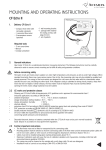
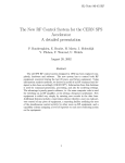
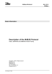
nova230 for M-Bus
nova230 for M-Bus
User's Manual
7000969003 N7
This description matches the current EPROM
release, Version G., and the M-Bus protocol
as per Version 4.8 of the M-Bus user group
description.
7000969003 N7
Sauter Systems
1
nova230 for M-Bus
2
7000969003 N7
Sauter Systems
nova230 for M-Bus
0
Table of contents
1 Purpose of this document .........................................................................................7
2 M-Bus technology in general.....................................................................................9
2.1 Historical overview of development .....................................................................9
2.2 Typical applications .............................................................................................9
2.3 Special features.................................................................................................10
2.4 Benefits and drawbacks of M-Bus technology...................................................11
2.5 Standardisation .................................................................................................11
2.6 Brief description.................................................................................................11
2.6.1 Hardware characteristics ...........................................................................11
2.6.2 Protocol description ...................................................................................13
3 nova230 and M-Bus ..................................................................................................15
3.1 Benefits of the system .......................................................................................15
3.2 System concept.................................................................................................16
3.3 Integration in the EY3600 System .....................................................................17
3.3.1 Datapoint list ..............................................................................................17
3.3.2 Address area..............................................................................................18
3.3.3 Connectable meters (electrical) .................................................................18
3.3.4 Time behaviour ..........................................................................................19
3.3.5 Fault detection ...........................................................................................19
3.3.6 Diagnosis ...................................................................................................19
3.3.6.1 Monitoring via the service interface ....................................................19
3.3.6.2 Monitoring via terminal 126 ................................................................20
3.3.6.3 Diagnosis menu..................................................................................21
3.3.7 Points to note for design engineering ........................................................21
3.4 Step-by-step instructions ...................................................................................22
3.4.1 Generating a datapoint list .........................................................................22
3.4.2 Create FBD diagram ..................................................................................24
3.4.3 Commissioning M-Bus ...............................................................................24
3.4.4 Configuration with MBusPara230 ..............................................................25
3.4.5 Configuration with the monitor program (without MBusPara230) ..............26
4 Annexe.......................................................................................................................27
4.1 Menu structure of the monitor program .............................................................27
4.2 Connection drawing...........................................................................................29
4.3 Bibliography and links .......................................................................................30
4.4 Recommended equipment ................................................................................30
4.4.1 Level converter ..........................................................................................30
4.4.2 Auxiliary programs .....................................................................................30
4.5 Positive list of checked meters and relevant documentation references...........31
4.6 Specific features of individual devices...............................................................32
4.6.1 M-Bus masters...........................................................................................32
7000969003 N7
Sauter Systems
3
nova230 for M-Bus
0
Table of contents
4.6.2 Content of the data telegram ..................................................................... 32
4.6.3 Battery-powered meters ............................................................................ 33
4.6.4 ABB/SVM F2 ............................................................................................. 33
4.6.5 Aquametro Calec MB, Amtron-Nx, Saphir-N and AMBUS IS .................... 33
4.6.6 Aquametro AMBUS IS ............................................................................... 33
4.6.7 Siemens Ultraheat 2WR4 and 2WR5 ........................................................ 33
4.6.8 Viterra Sensonic ........................................................................................ 33
4.7 Reference projects............................................................................................ 34
4.8 Who to contact .................................................................................................. 34
5 Index .......................................................................................................................... 35
5.1
4
Index ................................................................................................................. 35
7000969003 N7
Sauter Systems
nova230 for M-Bus
0
Table of contents
List of icons and symbols
Keyboard operation
Wait
Diskette
Mouse operation
Single mouse click with left button
Single mouse click with right button
Double mouse click with left button
Double mouse click with right button
Description
Application
Information
Attention
Note
7000969003 N7
Sauter Systems
5
nova230 for M-Bus
0
Table of contents
Trademarks
Designer
Micrografx Designer
Media Manager
Windows
Microsoft Office 97 Professional
MS Office
Microsoft Access 97
Microsoft Office 2000
Microsoft Word
Acrobat Reader
Pentium
6
7000969003 N7
Trademark of Micrografx, Inc.
Trademark of Micrografx, Inc.
Trademark of Micrografx, Inc.
Trademark of Microsoft Corporation
Trademark of Microsoft Corporation
Trademark of Microsoft Corporation
Trademark of Microsoft Corporation
Trademark of Microsoft Corporation
Trademark of Microsoft Corporation
Adobe Systems Incorporated
Trademark of Intel Corporation
Sauter Systems
nova230 for M-Bus
1
Purpose of this document
1 Purpose of this document
The first section of this document is intended to provide an overview of M-Bus technology, the areas in which it is used and the ways M-Bus devices are connected to the
EY3600 system.
This is followed by the second section, with the instructions for design engineering and
commissioning the M-Bus-specific functions.
nova230 is largely identical with nova210. For this reason, please refer to the documentation for the nova210 for a description of the AS functionality in general terms.
7000969003 N7
Sauter Systems
7
nova230 for M-Bus
1
8
Purpose of this document
7000969003 N7
Sauter Systems
nova230 for M-Bus
2
M-Bus technology in general
2 M-Bus technology in general
2.1
Historical overview of development
M-Bus stands for Meter Bus, and it was originally developed by the University of Paderborn, Texas Instruments and Techem AG, as a way of reading consumption meters at
low cost.
It is standardised, and most meter manufacturers offer M-Bus meters.
As time has gone on, meter performance levels have continued to rise. Whereas earlier
meters were just about able to transmit the meter reading, present-day models offer a
wide range of process data such as power, flow, and temperature, etc.
This opens up the possibility of integrating the meters into a management system via the
M-Bus.
2.2
Typical applications
The following applications are available for meters with an M-Bus interface:
•
•
•
•
Consumption cost charging: meter data are solely used for billing tenants or lessees; the meter data on specific billing dates are the only points of interest; typically,
reading takes place once a month.
Visualisation and evaluation of consumption data: the consumption data are
forwarded to a visualisation system. The historical data allow an analysis of energy
consumption, so that it can be optimised. In principle, it is also possible to record
load profiles for charging special tariffs. Special tariff devices which enable calibration are required for this purpose under certain circumstances, as stipulated by national legislation.
Building automation: the meters are used as field sensors. Measured values such
as power and forward or return flow temperature are used to control the heating installation or for load management purposes.
Pipe network monitoring for district heating supply.
The M-Bus has been particularly successful in areas where it delivers added-value as
compared with cheaper competing technologies such as manual reading, self-reading
and radio transmission.
This is especially true in situations:
• when readings are required more often than these other technologies would allow
• when more data are needed
• when the data are to be processed online
7000969003 N7
Sauter Systems
9
nova230 for M-Bus
2
M-Bus technology in general
The M-Bus is mainly used in building technology, and more particularly in the area of heat
quantity measurement; however, meters are available for virtually all types of media.
At least in terms of billing based on consumption, the M-Bus has not yet properly managed to establish its position in the supply industry. Although many energy suppliers are
running M-Bus pilot projects, they are adopting a “wait-and-see” attitude because competing technologies such as Powerline Carrier, radio reading, GSM and reading via television cables are developing at such a breathtaking pace. The IEC 1107 interface
(ZVEI-interface) has also established its position, particularly in the electricity industry.
2.3
Special features
The historical development of the M-Bus gave rise to the following requirements:
•
•
•
•
•
•
•
10
cheap hardware in the meter: the requirements imposed on the meter by hardware
and software are low; to economise on memory and processor capacity, the intelligence is transferred from the meter to the master.
suitability for battery-powered devices: data transmission should not reduce the
battery lifetime. To achieve this:
• the whole meter is supplied via the bus, or
• the data interface is supplied from the bus, or
• power is used sparingly, or
• bus accesses are restricted
cheap, straightforward cabling: the meters can be wired with normal 2-conductor
cables. Distances of several kilometres can be bridged, and the bus topology can be
adapted to the local circumstances. For short distances or small numbers of meters,
standard telephone cable is adequate. The master provides each meter with power
of 1.5 mA via the bus, and this can be used to supply the meter.
acceptable data security: understandably, customers and suppliers consider that
correct billing is very important; even so, the security requirements are lower than
those for other automation systems. To guarantee secure transmission in spite of
simple cabling, low transmission rates are used (2400 or 300 baud as a general rule)
together with efficient fault detection.
low realtime requirements: logically, the low transmission rates and the fault detection facility have an influence on the reading speed. The reading cycle can take several minutes, especially for large networks.
master-slave architecture: the M-Bus was originally designed to read meters on a
centralised basis, for example with the use of a reading service. This is why one
network must only ever contain one master which controls communication as a
whole. Meters cannot signal (or “report”) to the master spontaneously (in cases of
raster threshold or limit value violations, for example).
independent of specific manufacturers: because energy suppliers do not wish to
be tied to one meter manufacturer or system supplier, the bus should be standardised and it should be supported by as many manufacturers as possible.
7000969003 N7
Sauter Systems
nova230 for M-Bus
2
M-Bus technology in general
2.4
Benefits and drawbacks of M-Bus
technology
2.5
Standardisation
The M-Bus is standardised in EN 1434-3.
EN 1434 refers to IEC 870-5 for the definition of the link layer.
“M-Bus: A Documentation“ by the M-Bus User Group also represents the de facto
standard which is followed by most manufacturers (this can be downloaded at
WWW.M-Bus.COM).
These standards and directives define how communication between master and slave
functions, and how the values are represented.
These documents do not define which data are transmitted.
In other words, the data scope may vary from meter to meter.
The German District Heating Working Group [Arbeitsgemeinschaft Fernwärme, (AGFW)]
has also published a guideline on using heat meters in control engineering (this can be
downloaded at WWW.M-Bus.COM)
2.6
Brief description
2.6.1
Hardware characteristics
The M-Bus uses a normal unshielded two-wire line to transmit data.
To enable simple wiring and to exclude faults, the M-Bus is independent of polarity; this
means that the meters can be connected to the bus without taking account of polarity.
The data are transmitted from the master to the slaves by modulating the bus voltage.
When transmission is from one slave to the master, the slave modulates the current.
Mark
Space
Master->Slave
24 ... 36 V
Reduction by 12 V
Slave->Master
0 ... 1.5 mA
Increase by 11 ... 20 mA
Recognition of the Mark and Space statuses does not depend on the absolute voltage or
the absolute current, but on the change.
This means that the voltage drop along the line and the quiescent current of the connected meters do not have any influence.
This design makes it possible to connect and supply up to 250 meters.
7000969003 N7
Sauter Systems
11
nova230 for M-Bus
2
M-Bus technology in general
M-Bus
Master
Repeater
Depending on the line cross-section and the number of meters connected, the bus can
bridge distances of up to 1 km ; under certain conditions, distances of several kilometres are possible.
It is easy to adapt the bus topology to the local circumstances:
repeaters can be used to extend the bus (more meters, longer distances).
The master can consist either of an intelligent M-Bus centre, a PC with suitable software
and level converters, or an automation station with an M-Bus interface.
M-Bus centre
PC with
M-Bus software
RS232
M-Bus level
converter
Automation station
M-Bus network
12
7000969003 N7
Sauter Systems
nova230 for M-Bus
2
M-Bus technology in general
2.6.2
Protocol description
Work with nova230 does not require a precise knowledge of the M-Bus protocol; it is
sufficient to be familiar with the content of the telegram from the meters that are being
used. However, it is helpful to know the basics of M-Bus communication in order to have
a better understanding of the meter manufacturers’ protocol descriptions.
M-Bus communication is controlled by a Master. The slaves are only allowed to send
data on request. Consequently, spontaneous meter signals are impossible.
The M-Bus protocol allows two addressing modes: primary and secondary addressing.
With secondary addressing the meter is identified using the fabrication number and
the manufacturer’s code.
With primary addressing, a bus address is assigned to each meter within an M-Bus
network.
As a general rule, the meters are delivered with primary address 0, and this should be
set to a value between 1 and 250 during the configuration procedure. For networks with
more than 250 meters, it is only possible to use secondary addressing.
Address 254 can be used if there is a point-to-point connection (i.e. if only one single
slave is connected). Each connected meter “thinks” that it is being addressed, regardless of its address.
Address 255 can be used to send broadcast commands: all the connected meters
“think” that they are being addressed but they are not allowed to send any data back.
Typically, broadcast commands are used to set the time, the billing date or the baud rate
simultaneously on all meters.
The M-Bus uses asynchronous serial data transmission with 1 start bit, 8 data bits, even
parity and one stop bit. These eleven bits must be transmitted 1:1 throughout the entire
transmission chain. For example, if modems are installed in the section, they must be
suitable for 11-bit transmission.
The most commonly used transmission rate is 2400 baud, but older battery meters in
particular are sometimes set to 300 baud. Most meters support transmission speeds of
300, 2400 and 9600 baud, although most manufacturers advise against 9600 baud on
larger networks.
The M-Bus protocol only defines a very small number of commands:
• Request User Data 1: the master requests the slave’s alarm register
• Request User Data 2: the master requests the meter data
• Send User Data: the master sends data to the slave
• SND_NKE: the master requests an acknowledge signal from the slave (this is used
for automatic meter searching or to synchronise communication)
The slave responds to these commands with the desired data, or else not at all (for example, if the data have not been understood correctly).
A slave may never signal without being requested to do so.
7000969003 N7
Sauter Systems
13
nova230 for M-Bus
2
M-Bus technology in general
The slave can use two data formats for the response:
• the fixed data structure is used to transmit precisely two meter readings. The values are coded in binary or BCD format.
• the variable data structure is much more powerful: it can be used to transmit an
unspecified number of values. These may be instantaneous values such as temperature or power, as well as meter readings.
It is left up to the slave to choose which data it will use to reply. The standard telegram usually contains the most important meter data, but as a general rule, the data
can also be selected on a customer-specific basis.
The fixed data structure is only used rarely nowadays, and the M-Bus user group advises against using it.
How the variable data structure is built up
A variable data structure telegram consists of these components:
• a header; this contains items such as the address, the telegram length, the device
identification and the number of bus accesses.
• an unspecified number of datasets which, in turn, comprise:
• a Data Information Field, DIF; the DIF shows what the value means (examples:
“forward flow temperature“, “return flow temperature“ or “power“)
• possibly one or more extensions of the DIF (DIFE) – if one byte is not sufficient
• a Value Information Field; the VIF indicates the physical units and the resolution
• possibly one or more extensions of the VIF (VIFE) – if one byte is not sufficient
• the value itself
• the checksum of the data in the telegram, and a stop character
The total length of the telegram may be 252 bytes. If this is not long enough, several
telegrams can be chained (multi-telegram response).
14
7000969003 N7
Sauter Systems
nova230 for M-Bus
3
nova230 and M-Bus
3 nova230 and M-Bus
3.1
Benefits of the system
Using the M-Bus to connect the meters has the following benefits as compared with meter pulse transmission:
• even low-price meters offer numerous additional items of information such as power,
maxima, temperatures, etc...
• one bus line replaces a large number of pulse lines (and possibly analogue lines);
the cabling expenses are cut and fewer inputs are assigned on the AS
• interruptions of pulse transmission or AS operation do not give rise to metering faults
because the meter readings that are stored in the meter can always be transmitted
As compared with readings via an M-Bus master or a PC with M-Bus software, a direct
connection between the meters and the nova230 automation station offers these benefits:
• very compact solution for combined metering and control applications
• process variables recorded by the meters, such as temperature, power or flow rate,
can be used for control purposes
• the meter data can be forwarded to other AS’s in the network
• the nova230 can independently record historic data such as load profiles or monthly
values with no need for an extra PC to be online
• very high reliability, especially compared with PC based solutions
7000969003 N7
Sauter Systems
15
nova230 for M-Bus
3
nova230 and M-Bus
3.2
System concept
The EY3600 automation station, nova230, has been developed to connect M-Bus meters to the EY3600 system.
It is based on the EY3600 AS nova210, which has an M-Bus interface in addition to the
normal inputs and outputs and the AS functionality.
The AS reads the meters at periodic intervals, making the data available via soft addresses. The AS cannot send any values to the meter (in general, this is not usual for
meters).
The reading frequency for each meter depends primarily on the number of meters connected.
To configure the M-Bus communication, the station can be set to test mode with the help
of a jumper.
In this mode, a monitor program runs on the station; this can be operated via a serial
connection, using the PC’s terminal program (such as HyperTerminal).
The nova230 is only designed to read the meters, not to parameterise them.
Protocol analysis (below.
126)
Monitor (Service)
M-Bus
M-Bus extension
M-Bus fault
M-Bus
driver
Communication
processor
MFA 255
MFA 254
EEPROM
MFA 64
Configuration
AI, DI, CI
AO, DO
novaNet
User
EPROM
I/OHardware
(like
nova210)
MFA 60
ASProcessor
Control
Panel
Microprogr.
EPROM
MFA 0
The nova230 has the following EPROMS:
• Microprogram, EPROM-number 0501133.001: contains the station firmware
• User EPROM (optional): the “FBD-Layout“ of the station can be stored here
• Protocol EPROM, EPROM number 501129.001: contains the program for the communication processor; the M-Bus protocol is stored here, so to speak
• M-Bus configuration EEPROM: contains the M-Bus datapoint list and the M-Bus configuration data
16
7000969003 N7
Sauter Systems
nova230 for M-Bus
3
nova230 and M-Bus
3.3
Integration in the EY3600 System
3.3.1
Datapoint list
The datapoint list specifies which meter value is stored at which MFA.
The meters are addressed via their primary address. Within the response telegram of a
meter, the desired values are selected using the position. The content and sequence of
the telegram must be obtained by asking the meter manufacturer.
CASE FBD can be used to read the meter values via a soft input module. A total of
191 soft addresses for M-Bus transfers are available in the range from 254 to 64 .
Primary adr. 1
(Electricity)
2 Energy
3Power
List of data points, M-Bus
Primary adr. 2
(Water)
1 Volume
2 Flow rate
Primary adr. 3
(Heat)
5
Description of data points
Totalized energy, electricity
Power rate, electricity
Totalized volume, water
Flow rate, water
Totalized energy, heat
Power rate, heat
Flow rate, heat
MFA
254
253
252
251
250
249
248
Card code
0xD0 Counter
0x70 Analogue value
0xD0 Zaehler
0x70 Analogue value
0xD0 Counter
0x70 Analogue value
0x70 Analogue value
Slave
1
1
2
2
3
3
3
Position
2
3
1
2
1
3
4
Decimal point
0
0
0
0
0
0
0
1 Energy
2 Volume
3 Power
4 Flow rate
5 T forward flow
6 T return flow
The datapoint list can be generated on paper, or with Excel (e.g. using MBusPara230.XLS),
so that it can then be entered into the nova230 with the monitor program.
With EPROM versions from Release G onwards (Communication EPROM 0501129.001
Rel. G), the datapoint list can even be transferred directly into the nova230 using
MBusPara230.XLS.
7000969003 N7
Sauter Systems
17
nova230 for M-Bus
3
nova230 and M-Bus
The following values must be entered when the AS is being parameterised:
• datapoint description: freely available description field; not stored in the nova230
• MFA: address at which the value is entered in the nova230
• card code, valid values:
• 0xD0 for meter readings (such as volume, energy, service hours)
• 0x70 for analogue values (such as temperature, power, flow rate)
• slave: primary meter address
• position: position of the desired value within the response telegram
• first/following telegram: for meters with multi-telegram response, this indicates
whether the value is located in the first or second response telegram
• init-telegram: on meters with multi-telegram response, this forces transmission of
the first telegram
• decimal point: to shift the decimal point (this can be useful if the value range for the
value that is read exceeds the value range of the AS)
3.3.2
Address area
MFA’s 254 to 64 are available for the meter data. This means that there are 191 MFA’s
available for meter values.
Starting at 254, the addresses must be assigned in descending order.
To enable meter readings, each meter must have a unique primary address in the
range 1...250. This must be set in advance by the meter manufacturer or with the use of
a suitable tool.
3.3.3
Connectable meters (electrical)
A maximum of 50 meters can be connected directly to the nova230.
If more meters are to be connected, an M-Bus level converter can be connected via the
RS232 interface.
The M-Bus level converters from Aquametro and Padmess can be connected to the
nova230 using a serial modem cable (DB9 plug to DB9 socket)
AS side
(DB9 socket)
2 RXD
3 TXD
5 GND
18
7000969003 N7
⇐
⇒
⇔
Repeater side
(DB9 plug)
2 TXD
3 RXD
5 GND
Sauter Systems
nova230 for M-Bus
3
nova230 and M-Bus
3.3.4
Time behaviour
At 2400 baud, it takes approx. 1.5 seconds to interrogate one single meter.
This is independent of communication speed and telegram length. If several values are
requested from one meter, the meter is only read once.
If a meter does not respond, two more attempts are made to read it (corresponding to
approx. 6 sec with 2000 ms telegram waiting time), before the next MFA (!) is read.
In other words, if four MFA’s are assigned to one meter, there is a time delay of
4 x 6 sec if the meter cannot be read.
3.3.5
Fault detection
MFA 255 is reserved for alarm signals (card code 0x10).
Bit 0 of MFA 255 signals that communication has failed between nova230 and a meter.
It is reset as soon as a meter has been read successfully. The historical data from MFA
255 can be used for subsequent analysis of communication.
There are also two LED’s to signal status:
• “Cycle“: while the AS is being initialised, this is continuously lit; in normal operation,
it flashes while communication is in progress
• “Fault“: continuously lit LED signals an initialisation fault; flashing in normal operation signals a transmission fault
3.3.6
3.3.6.1
Diagnosis
Monitoring via the service interface
You can monitor M-Bus communication via the service interface, using a PC.
The bus communication is outputted 1:1 at the service interface. A hex terminal can be
used to display the M-Bus telegrams for analysis. However, they have to be interpreted
manually.
The cable is identical with the parameterisation cable for the 2400-substations.
Assignment:
AS side
Service interface
(DIN plug, 5-pin, 180°)
2 GND
5 TXD
3 RXD
⇔
⇒
⇐
PC side
COM port
(DB9 socket)
5 GND
2 RXD
3 TXD
Communication settings:
As for M-Bus communication
(i.e. usually 2400 baud, 8 data bits, 1 stop bit, parity even)
7000969003 N7
Sauter Systems
19
nova230 for M-Bus
3
nova230 and M-Bus
3.3.6.2
Monitoring via terminal 126
If the jumper is set to “Test“, communication is also logged at terminal 126. Unlike the
service interface, the data are decoded in this case .
Connection via terminal 126:
AS side
(terminal)
126 Δ
⇒
⊥
⇔
PC side
(DB9 plug)
1
2 RXD
3 TXD
4
5 GND
6
7
8
9
Communication settings:
8 data bits, 1 stop bit, no parity, 9600 baud
Example of output:
Abfrage:Slave 3
TX->107B037E16
Abfrage:Slave 3
TX->107B037E16
Abfrage:Slave 3
TX->107B037E16
Abfrage:Slave 1
TX->107B017C16
RX<686C6C6808017216997003B4058004BD10FFFF04071000000004150D000000426CFEF6440
700
00000082016C1F0C840107100000000322D20100052E00000000053E00000000055B0F4A0
243555B
FEFFFF7F055FC657CF41555FFEFFFF7F05632CBED0425563FFFFFF7F046D200B29023F16
Datenpunkt Nr1 nicht gefunden
Slave=1 Zaehler=2 MFA=254 Wert=
1.30 32 Bit Int
Slave=1 Zaehler=3 MFA=253 Wert=63230.00 16 Bit Int
Datenpunkt Nr4 nicht gefunden
20
7000969003 N7
Sauter Systems
nova230 for M-Bus
3
nova230 and M-Bus
Explanations:
1. The meter with primary address 3 is interrogated. The enquiry is first shown in plain
text and then as an M-Bus command (TX-> followed by a hexadecimal character
string). The meter does not respond, so the enquiry is repeated twice.
2. The meter with primary address 1 is interrogated; the response telegram is outputted
in hexadecimal form first.
Then the content of the response is shown in plain text:
the first and fourth values of the response telegram are not included in the datapoint
list (=are not used);
the second and fourth values are shown.
3.3.6.3
Diagnosis menu
The diagnosis menu is intended for examining the AS in the laboratory.
3.3.7
•
•
•
•
•
•
Points to note for design engineering
Obtain the current protocol description from the manufacturer, or confirm that the
available version is up to date
Suitability of meters:
• does the telegram contain the desired data?
• with a multi-telegram response: do the first two response telegrams contain the
data?
• are the meters suitable for continuous reading operation? (Be careful with battery-powered meters!)
• can all the meters be read with a common baud rate?
• pay attention to national calibration regulations: if the meters are used for billing
purposes, they must usually be approved in the country concerned
Configuring the meters: under certain circumstances, the baud rate, primary address
and content of the data telegram must be specified when ordering them, or at the
latest when the meters are commissioned
Pay attention to the units of measurement in the telegram: identical variables are
sometimes shown with different units on the meters, even when the meters are from
the same manufacturer (e.g. °C ↔ K or kWh ↔ MWh ↔ GJ)
Reading cycle: especially when a large number of meters have to be read and the
transmission quality is poor, the reading cycles may last several minutes
For larger installations, involve the manufacturer of the M-Bus technology in the
planning stage
7000969003 N7
Sauter Systems
21
nova230 for M-Bus
3
nova230 and M-Bus
3.4
Step-by-step instructions
3.4.1
Generating a datapoint list
You can generate the datapoint list with Excel file MBUS230Para.
The protocol description for the meters can be used to assign the values transferred
from the meter to the MFAs in the nova230.
REQ_UD2:
Response: Long:
DIF
04
04
42
44
82 01
84 01
03
05
05
05
55
05
55
05
55
04
VIF
VIF1
VIF2
6C
VIF1
6C
VIF1
22
2E
3E
5B
5B
5F
5F
63
63
6D
C=7B A=FE: 10
7B
FE
79
16
C=28 A=00 CI=72 03600000 AMT 80 Heat_(outlet) F0 10 FFFF [+ 16 DR(s)]
Meaning
Energy meter reading
Volume meter reading
Date – billing day 1
Energy meter reading on billing day 1
Date – billing day 2
Energy meter reading on billing day 2
Service hours [h]
Power [kW]
Flow rate [m3/h]
Forward flow temperature [°C]
max. forward flow temperature [°C]
Return flow temperature [°C]
max. return flow temperature [°C]
Temperature difference [K]
max. temperature difference [K]
Date+time
VIF1 and VIF2 are independent of the main resolution; a precise description is given in paragraph 4.6 below.
Extract from the protocol description for the Calec MB from Aquametro.
The sequence of data in the table is the decisive factor, from which the value for “position” is obtained in the datapoint list.
The energy meter reading is given card code 0xD0 (meter), and the analogue values are
given card code 0x70 (measured value).
The primary address of the meter is inserted in the “Slave“ column.
The meter does not send a multiple telegram, so the data all come in the first interrogation and there is no need for an init-telegram.
The decimal point is not shifted; the units for the energy and volume meter readings are
not indicated in the protocol, because they are parameterised individually for each device.
22
7000969003 N7
Sauter Systems
nova230 for M-Bus
3
nova230 and M-Bus
The list can now be stored.
Note: the program only functions if the file is saved in the directory where
MBUS230.XLS was installed.
Use the “Generate and download hex file” button to transfer the datapoint list to the
nova230. Follow the instructions in the program as you do this.
7000969003 N7
Sauter Systems
23
nova230 for M-Bus
3
nova230 and M-Bus
3.4.2
Create FBD diagram
The numerical values can be interrogated via a CI_Soft module and the analogue values
can be interrogated using an AI_Soft module.
3.4.3
Commissioning M-Bus
Before the nova230 goes into operation, the M-Bus installation should be started up and
checked.
1. Parameterising the meters:
• unique primary address: each meter must have a unique primary address between 1 and 250
• select the data you want, if necessary: you must make sure that the meter transfers the desired data. If the meter responds with several telegrams (multitelegram data), the desired data must be located in the first two telegrams.
• set all the meters to the same baud rate
The meters must be parameterised by the manufacturer, or with the tool which he
recommends.
24
7000969003 N7
Sauter Systems
nova230 for M-Bus
3
nova230 and M-Bus
2. Check the cabling of the M-Bus network (before connecting the meters):
• before connecting the M-Bus master: check for short circuits (between the bus
lines and/or against external voltages)
• after connecting the master: check for correct voltage, which must be between
24 and 36 V everywhere
3. Connect the meters to the M-Bus
4. Check the meters:
• do all the meters respond?
• have the primary addresses been assigned correctly?
• do they supply plausible results?
Smaller installations can be tested directly with the nova230 and HWC ; for larger installations, the job will be made considerably easier by using an M-Bus parameterisation program (such as M-Bus Application) and an additional master.
For larger networks, it is advisable to leave commissioning to the meter manufacturer or
to the M-Bus technology supplier.
3.4.4
Configuration with MBusPara230
Downloading with MBusPara230 only functions from software release G onwards
(Communication EPROM 0501129.001 Rel G)
1. Use the “Enter datapoint list“ command button to create a datapoint list with
MBusPara230.XLS
2. Use the “Enter communication parameters“ command button to parameterise
M-Bus communication and enter the installation name
3. Use the “Generate and download hex file“ command button to transfer the
data to the AS. Please follow the instructions in the program
4. The datapoint list can be saved. It must be stored in the MbusPara230 installation
directory
5. Switch the automation station on, disconnect the PC from the station and connect
the M-Bus
6. Set the jumper to “Run“ and switch the automation station on again
7000969003 N7
Sauter Systems
25
nova230 for M-Bus
3
nova230 and M-Bus
3.4.5
Configuration with the monitor program (without
MBusPara230)
1. Parameterising the meters:
• unique primary address: each meter must have a unique primary address between 1 and 250
• select the data you want, if necessary: you must make sure that the meter transfers the desired data. If the meter responds with several telegrams (multitelegram data), the desired data must be located in the first two telegrams
• set all the meters to the same baud rate
The tool recommended by the meter manufacturer must be used to parameterise the
meters.
2. Create the datapoint list
3. Switch the automation station off, disconnect the M-Bus and the service interface (if
necessary) from the station and connect the PC to the DB9 socket of the AS
4. Call up the terminal program (such as Hyperterminal from the ”Accessories“ program
group, connection data: 9600 baud, 8n1)
5. Plug the jumper into the “Test“ position and switch the AS on again
6. Press any key to start the monitor program
7. Use menu item “1=Parameterise configuration“ to enter the installation
name and the communication parameters
8. Use menu item “2=Parameterise new datapoint“ to enter the datapoints.
9. Use menu item “5=Write EPROM“ to save the datapoint list
10. Switch off the automation station, disconnect the PC from the station and connect
the M-Bus
11. Set the jumper to “Run“ and switch the automation station on again
26
7000969003 N7
Sauter Systems
nova230 for M-Bus
4
Annexe
4 Annexe
4.1
Menu structure of the monitor program
1= Konfiguration parametrieren
(1= Parameterise configuration)
• installation name
• parameterisation date
• waiting time for a telegram until timeout is detected
• baud rate
2= neuen Datenpunkt parametrieren
(2= Parameterise new datapoint)
• MFA
• card code (value or meter)
• slave or primary address of meter
• position (indicates the position of the desired value within the response telegram)
• shift decimal points
• send Init-telegram: on meters which respond with several telegrams, the Inittelegram forces the first telegram to be sent. It should always be sent when data
from the first telegram are requested with these meters.
• First interrogation/subsequent interrogation: is the desired value in the first or
second response telegram from the meter?
3= Datenpunkte auflisten
(3= List datapoints)
Lists all defined M-Bus datapoints
7000969003 N7
Sauter Systems
27
nova230 for M-Bus
4
Annexe
4= Diagnose-Menü
(4= Diagnosis menu)
The diagnosis menu is used to examine the nova230 in the laboratory.
A= Ausgabe aller CUI-Servicezaehler
(A= Output all CUI service counter)
C= CUI Diagnosezaehler
(C= CUI diagnosis counter)
D= DMA-Diagnosezaehler
(D= DMA diagnosis counter)
P= Protokoll-Diagnosezaehler
(P= Protocol - diagnosis counter)
S= Schnittstellenparameter
(S= Interface parameters)
V= Protokollparameter
(V= Protocol parameters)
W= Datenpunkte im Userprom
(W= Datapoints in userprom)
T= Treiber-Diagnosezaehler
(T= Driver diagnosis counter)
U= USER-EPROM Diagnosezaehler
(U= USER-EPROM diagnosis counter)
E= externes Speicherabbild
(E= External memory map)
I= internes Speicherabbild
(I= Internal memory map)
R= Ruecksetzen aller Diagnosezaehler
(R= Reset all diagnosis counter)
X= Speicherinitialisierung
(X= Initialise memory)
0= Daten Protokollierung einschalten
(0= Switch on datalogging)
1= Telegramm Protokollierung einschalten
(1= Switch on telegram logging)
2= Rueckkehr ins Hauptmenue
(2= Return to main menu)
5= EPROM schreiben
(5= Write EPROM )
The configuration of the M-Bus interface must be written to the EPROM so that it
is kept after a voltage failure
6= EPROM lesen
(6= Read EPROM )
28
7000969003 N7
Sauter Systems
nova230 for M-Bus
4
Annexe
4.2
Connection drawing
b
novaNet
a
novaNet
Data
User
501129.001
501130.001
a b a b
1
2
3
4
5
6
7
8
RS232
5 GND
2
Rx
3
Tx
CTS
8
RTS
7
230V~
Jumper
Monitor
2400 Bd
8 data bits
1 sto bit
even Parity
7000969003 N7
Monitor
9600 Bd
8 data bits
1 stop bit
no parity
M-Bus
501
502
503
504
MBusMBus+
MBusMBus+
Parametrisation
9600 Bd
8 data bits
1 stop bit
no parity
Sauter Systems
29
nova230 for M-Bus
4
Annexe
4.3
•
•
•
•
Bibliography and links
M-Bus homepage: WW.M-BUS.COM
EN 1434 Part 3
M-Bus: A Documentation (download at WWW.M-Bus.COM)
nova230-PDS, document no. 92.530
4.4
Recommended equipment
4.4.1
Level converter
An M-Bus level converter is essential in order to test and commission the meters.
Of course, the price increases with the number of meters that can be connected.
Small masters are adequate for “laboratory operation“ – examples include.
• Padmess Micro-Master (especially for laptops, powered by the notebook, up to
10 meters)
• Padmess PW 3 or PW 20 (up to 3 or 20 meters respectively)
• Aquametro ZS-5 (up to 5 meters, including power supply for Aquametro meters)
Masters with higher performance must be used as appropriate for larger installations.
4.4.2
Auxiliary programs
A PC program is necessary in addition to the level converter.
The M-Bus Application program can be used to analyse the meters’ M-Bus communication.
It can be used to search the network for meters.
It shows the data both as decoded values and also in hex format.
The meters can be configured with SND_UD commands (e.g. programming the primary
address or data selection).
Macros can be created and saved.
The program starts at a relatively low level of communication, meaning that M-Bus
knowledge is necessary to “tease out” the full performance.
It is available in two versions:
• DOS-Version: free download at WWW.M-Bus.COM
(filename: M-BUS124.EXE)
• 32-bit Windows version: download demo version at WWW.MICHAELRAC.COM, full
version costs approx. 400 Euro.
This version is considerably more powerful and user-friendly than the DOS version.
If you work with the M-Bus on a regular basis, the investment of 400 Euros is worthwhile because the license applies to an entire location (i.e. a whole NSO)!
30
7000969003 N7
Sauter Systems
nova230 for M-Bus
4
Annexe
4.5
Positive list of checked meters and
relevant documentation references
Medium
Heat
Manufacturer
Type
Contact address
ABB/SVM
Allmess
840
CF50
Aquametro
Calec MB
www.abb.com
www.allmess.de
+49/4361/625-0
www.aquametro.ch
+41/61/725 11 22
GWF/ Schinzel
IWKA
Calec light
MWZ 03
autarkon
Landis & Staefa/ Siemens Building Control
SONOGYR
WSD/WSF/WSG
Spanner Pollux
101/501
Siemens
Techem
Water
Viterra
Hydrometer
Ultraheat 2WR4
Delta Tech Compact
Delta Tech split
Istameter
ScampY
Power
Techem
EMH
FlYpper
Aquatech
EIZ
Aquametro
Padmess
AMBUS IS
Padpuls M1
Aquametro
Padpuls M 4
AMBUS ZS
Pulses
M-Bus level
converters
and masters
www.gwf.ch
www.danfoss-iwk.de
+49/7244/7205-0
www.sibt.com
www2.landisstaefa.com
+41/41/724 24 24
www.spanner-pollux.de
+49/621/6904-0
www.siemet.com
www.techem.de
+49/69/66 39 0
www.viterra-es.com
www.hydrometer.de
+49/981/18 06-0
www.emh.de
+49/38852/645-0
www.padmess.de
+49/5251/17690
AMBUS FA
Padmess
Have you had any experience with other meters?
Please inform us so that we can complete the list!
Contact: Cristóbal Fernández, SBA/MPS, +41/61/695 55 45
7000969003 N7
Sauter Systems
31
nova230 for M-Bus
4
Annexe
4.6
Specific features of individual devices
4.6.1
M-Bus masters
Special caution is required with intelligent M-Bus masters.
Intelligent centres make it possible to read the meters manually via the keyboard, or
automatically according to the time program.
As the M-Bus only allows one single master, there may be a data collision if the meters
are addressed by the master while the nova230 is active.
This can cause interruptions to communication lasting several minutes during this time.
Automation station
M-Bus master
Caution with:
•
manual reading via the keyboard
•
automatic reading with the master
•
automatic bus control with the master (e.g. with Aquametro AMBUS FA)
4.6.2
Content of the data telegram
The standard does not specify which data the telegram must contain, only how the information is coded.
It is left up to the meter to “decide” what content is transmitted, in which sequence and in
which numerical format; the master is responsible for interpreting it correctly.
As standard, most meters supply all the important items of information.
It is also possible to configure the content of the telegram on an application-specific basis, using the Send User Data command.
There is a description of the process for this purpose in Chapter 6.4.3 of “M-Bus:
A Documentation“.
For example, the “M-Bus Application“ program can be used to configure the data output.
Not all meters accept the standard procedure for data selection.
In some cases, data selection is only possible with manufacturer-specific equipment, if
at all.
The meter does not signal if it cannot supply the requested data. The master itself must
recognise that the selection has failed.
32
7000969003 N7
Sauter Systems
nova230 for M-Bus
4
Annexe
4.6.3
Battery-powered meters
Many battery-powered meters limit the number of bus accesses in order to protect the
battery; once there have been 30 accesses on the same day, for example, the meter
may not respond to any more interrogations until the following day.
Some manufacturers guarantee the full battery lifetime only if the meter is read out once
a day or less.
As the nova230 reads out the meters continuously, we strongly recommend to ask for a
(written) confirmation of the suitability of the meter for this application.
4.6.4
ABB/SVM F2
On the battery version with Pt 100 sensors the lifetime is not guaranteed if the meter is
read out "very often".
According to the manufacturer, the version with Pt 500 sensors is powered via the M-Bus.
4.6.5
•
•
•
Aquametro Calec MB, Amtron-Nx, Saphir-N and
AMBUS IS
These meters do not have battery buffers; they do not continue to calculate during a
voltage cut, but the meter data are preserved.
After a power cut, the data selection is lost and the meter responds with the standard
telegram again.
The M-Bus from Aquametro has two extra lines which can be used to supply power
to the meters. The Calec MB and the AMTRON-NW can also be supplied with 230 V
AC on site; however, all the other meters rely on the supply via the bus.
At the planning stage, it must be remembered that these supply units must have a
larger cross-section than normal M-Bus lines due to the currents that occur.
4.6.6
Aquametro AMBUS IS
The instantaneous values for power or flow always supply value 0.
4.6.7
Siemens Ultraheat 2WR4 and 2WR5
According to the manufacturer, battery lifetime is not affected by permanent readout, but
the data transmitted by the M-Bus is only updated every 15 minutes.
The meter can be set into a fast-readout mode that allows readout intervals down to four
seconds. In this mode the meter stores new data in the interface immediately after readout. This data will be sent in the next transmission. This means that the transmitted data
maybe several minutes old.
4.6.8
Viterra Sensonic
Communication problems have been reported for the Sensonic.
We are in contact with Viterra to fix the problem.
Please ask SBA/MPS for the latest news!
7000969003 N7
Sauter Systems
33
nova230 for M-Bus
4
Annexe
4.7
•
•
Reference projects
Eyecatcher at Swissbau 99
Roman Thermal Baths at Baden near Vienna
4.8
Who to contact
Your contact for M-Bus at Sauter:
Cristóbal Fernández
[email protected]
Tel. +41/61/695 55 45
34
7000969003 N7
Sauter Systems
nova230 for M-Bus
5
Index
5 Index
5.1
Index
alarm signals ....................................................19
auxiliary programs ............................................30
battery-powered meters.............................. 10, 33
card code..........................................................18
configuring the meters ......................................21
connection drawing...........................................29
cycle .................................................................19
Data Information Field DIF ...............................14
Data telegram, content of .................................32
datapoint description ........................................18
decimal point ....................................................18
diagnosis ..........................................................19
DIF....................................................................14
EN 1434 ..................................................... 11, 30
EPROM ............................................................16
fault...................................................................19
fault detection ...................................................19
FBD ..................................................................24
following telegram.............................................18
header ..............................................................14
IEC 870 ............................................................11
init-telegram......................................................18
LED ..................................................................19
level converter ..................................................12
Level converter .................................................30
mark .................................................................11
master ............................................ 10, 11, 13, 32
7000969003 N7
master-slave architecture................................. 10
M-Bus centre.................................................... 12
M-Bus usergroup ............................................. 11
MBusPara230 .......................................17, 25, 26
MFA ................................................................. 18
monitor program............................................... 27
monitoring the communication ......................... 20
parameterising the meters ............................... 24
position ............................................................ 18
primary address ............................................... 18
primary addressing .......................................... 13
protocol EPROM .............................................. 16
Request User Data .......................................... 13
secondary addressing...................................... 13
Send User Data ............................................... 13
service interface............................................... 19
slave ...........................................................13, 18
SND_NKE ........................................................ 13
space ............................................................... 11
standardisation................................................. 11
step-by-step instructions .................................. 22
time behaviour ................................................. 19
user EPROM.................................................... 16
value Information Field VIF .............................. 14
variable data structure ..................................... 14
VIF ................................................................... 14
Sauter Systems
35
nova230 for M-Bus
5
36
Index
7000969003 N7
Sauter Systems