1
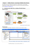
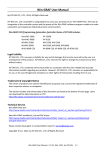
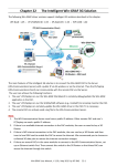
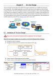
Chapter 3
Modbus Slave: Allow the SCADA/HMI Software to
Access Win-GRAF Variables
In Chapter2, we have described how to get/set the PAC system time (i.e., the “PAC_Time” program) and
create a blinking function (i.e., the “LD1” program) in the “Demo01” project. The following sections
describe how to allow the SCADA/HMI software (e.g., “InduSoft”) to access Win-GRAF variables that
defined in the "Demo01" project. The Win-GRAF Workbench provides two ways to open the PAC data,
one way is to enable the Win-GRAF PAC as a Modbus TCP Slave and the second way is to enable the
Win-GRAF PAC as a Modbus RTU Slave (you must first complete all the Modbus Slave settings in Section
3.1, and then refer the Section 3.2). To begin, follow these steps:
3.1 To Enable the Win-GRAF PAC as a Modbus TCP Slave
1. Click the “Open Fieldbus Configuration” tool button to open the “IO Drivers” window.
2. Click the “Insert Configuration” button on the left side of the “IO Drivers” window and then select the
“MOSBUS Slave” and click “OK” to enable a Modbus TCP Slave.
Win-GRAF User Manual, V 1.02, Mar. 2015 by ICP DAS
3-1
3. Click the “Insert Master/Port” button on the left side to set the “Slave number” (In this case, the
value is “1”), and click the “OK” button.
4. Click the “Insert Slave/Data Block” button on the left side to open the “MODBUS Slave Request”
window.
Tips:
1. Press the “F1” key to open the Help on this subject.
2. If you add two or more “Server - …” settings, type a
“Server ID” for easier use (a string, e.g., `SVR1’)
5. Enter a simple note in the “Description”
field and then click the "Input Registers”
option.
For Modbus Master to Read data:
Options
Data types
Input-bits
BOOL
BYTE, INT, DINT,
Input Registers
REAL, etc.
Enter a simple note.
For Modbus Master to Write data:
Options
Data types
Coil-bits
BOOL
Holding
BYTE, INT, DINT,
Registers
REAL, etc.
(Refer the Appendix A to see more data type)
Win-GRAF User Manual, V 1.02, Mar. 2015 by ICP DAS
Recommend to set
“Base address” to “1”
and set the value of
“Nb items” is greater
than “200”.
3-2
6. As the screenshot above, it’s recommended to set the “Base address” to “1” and the “Nb items”
refers to how much variable data can be provided by one “data block”. If the data address requested
from the Modbus Master (e.g., the SCADA software) is greater than this value (in this example, the
value is “2000”), the Modbus Slave (i.e., Win-GRAF PAC) will not respond.
7. Mouse drags all the needed variables (e.g., “PAC_xxx”, data type: “DINT”) one-by-one from the
Variables area and then drop it to the “Symbol” field.
8. Mouse double-click the “Offset” field and fill in a value, then press “Enter” key to finish the setting.
Note: (1) The “Offset” value starts at “0” and the Modbus address of variable is equal to this value
plus 1 (Base address).
(2) If using a 32-bits (or more than 32-bits) data type (e.g., “DINT”, refer the Appendix A), it
requires two Modbus addresses, as the table below, the “Offset” values are 0, 2, 4, 6, etc.
Enter
Tips:
Mouse click the “Offset” field and press the keyboard “Ctrl+A” to select all items, and then click the
“Iterate Property” button at the left-side to open the settings window.
Ctrl+A
Win-GRAF User Manual, V 1.02, Mar. 2015 by ICP DAS
3-3
Keep the “Name” setting, enter “0” into “From” field and enter “2” into “By” field, then click “OK”.
(If setting the “Name” to “%%”, it will show “00, 22,
44, 66, 88, 1010, 1212” in this example. To modify it
depends on the required settings and then check
the value in the “Results” area.)
9. Click “Storage” to select entire columns and then press “Enter” key to display a drop-down menu.
Then, select “DWORD (Low – High)” and press “Enter” key to complete the setting. (If using a 16-bits
or below, it’s no need to set the “Storage” item.)
To expand this “Data Block” and you can see the Modbus addresses of all variables. It equals to the
“Offset” value plus 1 (Base address).
Win-GRAF User Manual, V 1.02, Mar. 2015 by ICP DAS
3-4
10. Then, we need to add the second “Data Block” for the Modbus Master to read the Boolean data.
This configure way is similar to the step 4 to 8:
(1) Click the “Server - …” item and click the “Insert Slave/Data Block” button at the left side to open
the settings window.
(2) In the “MODBUS Slave Request” window, enter a simple note and select the “Input-bits” option,
then set “Base address” to “1” and set “Nb items” to “2000”.
Enter a simple note
For the Modbus Master to Read data:
Option
Data Type
Input Bits
BOOL
BYTE, INT, DWORD,
Input Registers
REAL, LINT, etc.
(Refer Appendix A to see more data type)
(3) Mouse drags the Boolean variables (i.e., “LED1”, “LED2”; data type: BOOL) one-by-one and drop
them to the “Symbol” area, and then set the “Offset” to “0” and to “1”.
You have completed the settings for the Modbus Slave. Finally, follow the way below to re-compile
the program and download it to the Win-GRAF PAC.
Win-GRAF User Manual, V 1.02, Mar. 2015 by ICP DAS
3-5
11. Click “Project” > “Build All Projects” from the menu bar to compile this program again (refer the
Section 2.3.4). If a message informs you “No error detected” that means this process is successful.
This version information can be ignored.
12. Mouse right-click the project name (i.e., “Demo01”) and select the “Communication Parameters…”
to set the PAC IP (e.g., “192.168.71.19:502”) and then click the menu bar “Project” > “On Line” (or
) to establish a connection and download this project to the Win-GRAF PAC. (Refer the Section
2.3.5).
SCADA / HMI
Win-GRAF PAC
IP: 192.168.71.19
Port: 502
InduSoft
Slave number = 1
WP-5xx8
Modbus TCP Master
WP-8xx8
Modbus TCP Slave
(Refer the P1-1 to view all PAC models)
After completing all the steps, the HMI/SCADA software can access to all the Win-GRAF variables listed
above via Modbus TCP protocol.
Win-GRAF User Manual, V 1.02, Mar. 2015 by ICP DAS
3-6
3.2 To Enable the Win-GRAF PAC as a Modbus RTU Slave
Before doing this, you must complete all the content that described in Section 3.1 to open the Modbus
Slave data. The way to enable the Win-GRAF PAC as the Modbus RTU Slave is to add the “MBSLAVERTU”
or the “MBSLAVERTUEX” function block in the program. To begin, follow these steps:
Add the “MBSLAVERTU” function block
1. In the “LD1” window, mouse click the place where you want to add this function block and then click
the “Insert FB..” button on the left side of the window.
3
2
1
2. Double-click on this function block and select the name “MBSLAVERTU”, then click “OK”.
Tips:
Press “MBSL” key to quickly
find out the function name.
Win-GRAF User Manual, V 1.02, Mar. 2015 by ICP DAS
3-7
3. In the “MBSLAVERTU” function block, mouse double-click the left side of the “PORT” and enter a
string 'COM2:9600,N,8,1' (it means using the Win-GRAF PAC’s COM2 to communication with the
Modbus Master) and then click
to complete the settings.
Tips:
Press the “F1” key on this
function block to show up
the related Help.
4. Double-click the left side of the “SLV” and then enter “1” (the value set in the Section 3.1 - Step 3),
then click
to finish the setting.
Now, you have completed the setting of the “MBSLAVERTU” function block, then re-compile the
program and download it to the Win-GRAF PAC. (Refer the Section 2.3.4, Section 2.3.5)
Note: Users can enable multiple Modbus RTU Slave ports for each PAC (recommend not over 16 Ports),
the way is to add multiple “MBSLAVERTU” function blocks and set the different “Port” value.
Win-GRAF User Manual, V 1.02, Mar. 2015 by ICP DAS
3-8
SCADA / HMI
Win-GRAF PAC
COM2: RS-232
9600,N,8,1
InduSoft
Slave number = 1
Modbus RTU Master
WP-5xx8
WP-8xx8
Modbus RTU Slave
(Refer the P1-1 to view all PAC models)
Add the “MBSLAVERTUEX” function block
If you have added multiple “Server - …” settings (recommend to set one) in the “IO Drivers” window, the
“MBSLAVERTUEX” function block must be used.
1. Follow the step1 to 4 described above to add the “MBSLAVERTUEX” function block. If you want to
change the usage for existing function block, mouse double-click the “MBSLAVERTU” and change it
to the“MBSLAVERTUEX”, and then click the “OK” button.
Function
Function Block
Win-GRAF User Manual, V 1.02, Mar. 2015 by ICP DAS
3-9
2. The “MBSLAVERTUEX” has a “SrvID” setting. Double click the left side of the “SrvID” and enter a
needed “Server ID” (using a string format, e.g., ‘Svr1’).
Note:
Using the “MBSLAVERTU” function block means the first Mobus Slave setting will be enabled.
Using the “MBSLAVERTUEX” function block means to enable the Modbus Slave setting depends on
the “Server ID”.
Tips:
Press the “F1” on this
function block to show
up the related Help.
Now, you have finished the settings for the “MBSLAVERTUEX” function block and then re-compile
the program and download it to the Win-GRAF PAC. (Refer the Section 2.3.4, Section 2.3.5)
Win-GRAF User Manual, V 1.02, Mar. 2015 by ICP DAS
3-10