1
PRELIMINARY
Annotator
Annotation Graphics Processor
68-1661-01
Rev. Ax2
09 09
Precautions
Warning
This symbol is intended to alert the user of important operating and maintenance
(servicing) instructions in the literature provided with the equipment.
Power sources • This equipment should be operated only from the power source indicated on the product. This
equipment is intended to be used with a main power system with a grounded (neutral) conductor. The
third (grounding) pin is a safety feature, do not attempt to bypass or disable it.
This symbol is intended to alert the user of the presence of uninsulated dangerous
voltage within the product’s enclosure that may present a risk of electric shock.
Power disconnection • To remove power from the equipment safely, remove all power cords from the rear of
the equipment, or the desktop power module (if detachable), or from the power source receptacle (wall
plug).
Caution
Read Instructions • Read and understand all safety and operating instructions before using the equipment.
Retain Instructions • The safety instructions should be kept for future reference.
Follow Warnings • Follow all warnings and instructions marked on the equipment or in the user
information.
Avoid Attachments • Do not use tools or attachments that are not recommended by the equipment
manufacturer because they may be hazardous.
Consignes de Sécurité • Français
Power cord protection • Power cords should be routed so that they are not likely to be stepped on or pinched by
items placed upon or against them.
Servicing • Refer all servicing to qualified service personnel. There are no user-serviceable parts inside. To
prevent the risk of shock, do not attempt to service this equipment yourself because opening or removing
covers may expose you to dangerous voltage or other hazards.
Slots and openings • If the equipment has slots or holes in the enclosure, these are provided to prevent
overheating of sensitive components inside. These openings must never be blocked by other objects.
Lithium battery • There is a danger of explosion if battery is incorrectly replaced. Replace it only with the
same or equivalent type recommended by the manufacturer. Dispose of used batteries according to the
manufacturer’s instructions.
Avertissement
Ce symbole sert à avertir l’utilisateur que la documentation fournie avec le matériel
contient des instructions importantes concernant l’exploitation et la maintenance
(réparation).
Alimentations• Ne faire fonctionner ce matériel qu’avec la source d’alimentation indiquée sur l’appareil. Ce
matériel doit être utilisé avec une alimentation principale comportant un fil de terre (neutre). Le troisième
contact (de mise à la terre) constitue un dispositif de sécurité : n’essayez pas de la contourner ni de la
désactiver.
Ce symbole sert à avertir l’utilisateur de la présence dans le boîtier de l’appareil
de tensions dangereuses non isolées posant des risques d’électrocution.
Déconnexion de l’alimentation• Pour mettre le matériel hors tension sans danger, déconnectez tous les cordons
d’alimentation de l’arrière de l’appareil ou du module d’alimentation de bureau (s’il est amovible) ou
encore de la prise secteur.
Attention
Lire les instructions• Prendre connaissance de toutes les consignes de sécurité et d’exploitation avant
d’utiliser le matériel.
Conserver les instructions• Ranger les consignes de sécurité afin de pouvoir les consulter à l’avenir.
Respecter les avertissements • Observer tous les avertissements et consignes marqués sur le matériel ou
présentés dans la documentation utilisateur.
Eviter les pièces de fixation • Ne pas utiliser de pièces de fixation ni d’outils non recommandés par le
fabricant du matériel car cela risquerait de poser certains dangers.
Protection du cordon d’alimentation • Acheminer les cordons d’alimentation de manière à ce que personne ne
risque de marcher dessus et à ce qu’ils ne soient pas écrasés ou pincés par des objets.
Réparation-maintenance • Faire exécuter toutes les interventions de réparation-maintenance par un technicien
qualifié. Aucun des éléments internes ne peut être réparé par l’utilisateur. Afin d’éviter tout danger
d’électrocution, l’utilisateur ne doit pas essayer de procéder lui-même à ces opérations car l’ouverture ou le
retrait des couvercles risquent de l’exposer à de hautes tensions et autres dangers.
Fentes et orifices • Si le boîtier de l’appareil comporte des fentes ou des orifices, ceux-ci servent à empêcher
les composants internes sensibles de surchauffer. Ces ouvertures ne doivent jamais être bloquées par des
objets.
Lithium Batterie • Il a danger d’explosion s’ll y a remplacment incorrect de la batterie. Remplacer uniquement
avec une batterie du meme type ou d’un ype equivalent recommande par le constructeur. Mettre au reut les
batteries usagees conformement aux instructions du fabricant.
Sicherheitsanleitungen • Deutsch
Vorsicht
Dieses Symbol soll dem Benutzer in der im Lieferumfang enthaltenen
Dokumentation besonders wichtige Hinweise zur Bedienung und Wartung
(Instandhaltung) geben.
Stromquellen • Dieses Gerät sollte nur über die auf dem Produkt angegebene Stromquelle betrieben werden.
Dieses Gerät wurde für eine Verwendung mit einer Hauptstromleitung mit einem geerdeten (neutralen)
Leiter konzipiert. Der dritte Kontakt ist für einen Erdanschluß, und stellt eine Sicherheitsfunktion dar. Diese
sollte nicht umgangen oder außer Betrieb gesetzt werden.
Dieses Symbol soll den Benutzer darauf aufmerksam machen, daß im Inneren des
Gehäuses dieses Produktes gefährliche Spannungen, die nicht isoliert sind und
die einen elektrischen Schock verursachen können, herrschen.
Stromunterbrechung • Um das Gerät auf sichere Weise vom Netz zu trennen, sollten Sie alle Netzkabel
aus der Rückseite des Gerätes, aus der externen Stomversorgung (falls dies möglich ist) oder aus der
Wandsteckdose ziehen.
Achtung
Lesen der Anleitungen • Bevor Sie das Gerät zum ersten Mal verwenden, sollten Sie alle Sicherheits-und
Bedienungsanleitungen genau durchlesen und verstehen.
Aufbewahren der Anleitungen • Die Hinweise zur elektrischen Sicherheit des Produktes sollten Sie
aufbewahren, damit Sie im Bedarfsfall darauf zurückgreifen können.
Befolgen der Warnhinweise • Befolgen Sie alle Warnhinweise und Anleitungen auf dem Gerät oder in der
Benutzerdokumentation.
Keine Zusatzgeräte • Verwenden Sie keine Werkzeuge oder Zusatzgeräte, die nicht ausdrücklich vom
Hersteller empfohlen wurden, da diese eine Gefahrenquelle darstellen können.
Instrucciones de seguridad • Español
Schutz des Netzkabels • Netzkabel sollten stets so verlegt werden, daß sie nicht im Weg liegen und niemand
darauf treten kann oder Objekte darauf- oder unmittelbar dagegengestellt werden können.
Wartung • Alle Wartungsmaßnahmen sollten nur von qualifiziertem Servicepersonal durchgeführt werden.
Die internen Komponenten des Gerätes sind wartungsfrei. Zur Vermeidung eines elektrischen Schocks
versuchen Sie in keinem Fall, dieses Gerät selbst öffnen, da beim Entfernen der Abdeckungen die Gefahr
eines elektrischen Schlags und/oder andere Gefahren bestehen.
Schlitze und Öffnungen • Wenn das Gerät Schlitze oder Löcher im Gehäuse aufweist, dienen diese zur
Vermeidung einer Überhitzung der empfindlichen Teile im Inneren. Diese Öffnungen dürfen niemals von
anderen Objekten blockiert werden.
Litium-Batterie • Explosionsgefahr, falls die Batterie nicht richtig ersetzt wird. Ersetzen Sie verbrauchte
Batterien nur durch den gleichen oder einen vergleichbaren Batterietyp, der auch vom Hersteller
empfohlen wird. Entsorgen Sie verbrauchte Batterien bitte gemäß den Herstelleranweisungen.
Advertencia
Este símbolo se utiliza para advertir al usuario sobre instrucciones importantes
de operación y mantenimiento (o cambio de partes) que se desean destacar en el
contenido de la documentación suministrada con los equipos.
Alimentación eléctrica • Este equipo debe conectarse únicamente a la fuente/tipo de alimentación eléctrica
indicada en el mismo. La alimentación eléctrica de este equipo debe provenir de un sistema de distribución
general con conductor neutro a tierra. La tercera pata (puesta a tierra) es una medida de seguridad, no
puentearia ni eliminaria.
Este símbolo se utiliza para advertir al usuario sobre la presencia de elementos con
voltaje peligroso sin protección aislante, que puedan encontrarse dentro de la caja
o alojamiento del producto, y que puedan representar riesgo de electrocución.
Desconexión de alimentación eléctrica • Para desconectar con seguridad la acometida de alimentación eléctrica
al equipo, desenchufar todos los cables de alimentación en el panel trasero del equipo, o desenchufar el
módulo de alimentación (si fuera independiente), o desenchufar el cable del receptáculo de la pared.
Precaucion
Leer las instrucciones • Leer y analizar todas las instrucciones de operación y seguridad, antes de usar el
equipo.
Conservar las instrucciones • Conservar las instrucciones de seguridad para futura consulta.
Obedecer las advertencias • Todas las advertencias e instrucciones marcadas en el equipo o en la
documentación del usuario, deben ser obedecidas.
Evitar el uso de accesorios • No usar herramientas o accesorios que no sean especificamente recomendados
por el fabricante, ya que podrian implicar riesgos.
安全须知 • 中文
这个符号提示用户该设备用户手册中有重要的操作和维护说明。
这个符号警告用户该设备机壳内有暴露的危险电压,有触电危险。
注意
阅读说明书 • 用户使用该设备前必须阅读并理解所有安全和使用说明。
保存说明书 • 用户应保存安全说明书以备将来使用。
遵守警告 • 用户应遵守产品和用户指南上的所有安全和操作说明。
避免追加 • 不要使用该产品厂商没有推荐的工具或追加设备,以避免危险。
Protección del cables de alimentación • Los cables de alimentación eléctrica se deben instalar en lugares donde
no sean pisados ni apretados por objetos que se puedan apoyar sobre ellos.
Reparaciones/mantenimiento • Solicitar siempre los servicios técnicos de personal calificado. En el interior no
hay partes a las que el usuario deba acceder. Para evitar riesgo de electrocución, no intentar personalmente
la reparación/mantenimiento de este equipo, ya que al abrir o extraer las tapas puede quedar expuesto a
voltajes peligrosos u otros riesgos.
Ranuras y aberturas • Si el equipo posee ranuras o orificios en su caja/alojamiento, es para evitar el
sobrecalientamiento de componentes internos sensibles. Estas aberturas nunca se deben obstruir con otros
objetos.
Batería de litio • Existe riesgo de explosión si esta batería se coloca en la posición incorrecta. Cambiar esta
batería únicamente con el mismo tipo (o su equivalente) recomendado por el fabricante. Desachar las
baterías usadas siguiendo las instrucciones del fabricante.
警告
电源 • 该设备只能使用产品上标明的电源。 设备必须使用有地线的供电系统供电。 第三条线
(地线)是安全设施,不能不用或跳过 。
拔掉电源 • 为安全地从设备拔掉电源,请拔掉所有设备后或桌面电源的电源线,或任何接到市
电系统的电源线。
电源线保护 • 妥善布线, 避免被踩踏,或重物挤压。
维护 • 所有维修必须由认证的维修人员进行。 设备内部没有用户可以更换的零件。为避免出现
触电危险不要自己试图打开设备盖子维修该设备。
通风孔 • 有些设备机壳上有通风槽或孔,它们是用来防止机内敏感元件过热。 不要用任何东
西挡住通风孔。
锂电池 • 不正确的更换电池会有爆炸的危险。必须使用与厂家推荐的相同或相近型号的电池。
按照生产厂的建议处理废弃电池。
PRELIMINARY
Safety Instructions • English
声明
所使用电源为 A 级产品,在生活环境中,该产品可能会造成无线电干扰。在这种情况下,可能需要用户对其干扰采取切实可行的措施。
FCC Class A Notice
This equipment has been tested and found to comply with the limits for a Class A digital device, pursuant to part 15 of the FCC Rules. Operation is subject to
the following two conditions: (1) this device may not cause harmful interference, and (2) this device must accept any interference received, including interference
that may cause undesired operation. The Class A limits are designed to provide reasonable protection against harmful interference when the equipment is
operated in a commercial environment. This equipment generates, uses, and can radiate radio frequency energy and, if not installed and used in accordance with
the instruction manual, may cause harmful interference to radio communications. Operation of this equipment in a residential area is likely to cause harmful
interference, in which case the user will be required to correct the interference at his own expense.
This unit was tested with shielded cables on the peripheral devices. Shielded cables must be used with the unit to ensure compliance with FCC emissions limits.
For more information on safety guidelines, regulatory compliances,
EMI/EMF compliance, accessibility, and related topics, click here.
PRELIMINARY
N
Table of Contents
Chapter One • Introduction . ..................................................................................................... 1-1
About this Manual..................................................................................................................... 1-2
About the Annotator................................................................................................................ 1-2
Definitions. ..................................................................................................................................... 1-3
Features. ........................................................................................................................................... 1-4
Chapter Two • Installation ......................................................................................................... 2-1
U/L Safety Requirements........................................................................................................ 2-2
Important safety instructions................................................................................................... 2-2
Mounting the Annotator. ...................................................................................................... 2-3
Rear Panel Features and Connections............................................................................ 2-4
Power and video input connections....................................................................................... 2-4
Output, user interface, and control connections.................................................................. 2-5
Installation and cabling............................................................................................................ 2-6
Powering Up................................................................................................................................... 2-6
Default display cycle.................................................................................................................. 2-7
Resetting the Unit with the Reset Button................................................................... 2-7
Chapter Three • Front Panel Operation............................................................................ 3-1
Front Panel Overview............................................................................................................... 3-2
Switching Inputs......................................................................................................................... 3-3
Button Backlighting.................................................................................................................. 3-3
The Annotator Menu System. ............................................................................................. 3-4
Overview of menus............................................................................................................. 3-4
User Presets. ......................................................................................................................... 3-4
Input Configuration............................................................................................................. 3-4
Output Configuration.......................................................................................................... 3-4
Advanced Configuration. .................................................................................................... 3-4
View Comm Settings............................................................................................................ 3-4
Edit Comm Settings (hidden)............................................................................................... 3-4
Exit menu.............................................................................................................................. 3-4
Scan Converter Configuration............................................................................................. 3-4
Using the menus................................................................................................................. 3-5
User presets......................................................................................................................... 3-6
Save a user preset. ............................................................................................................... 3-6
Recall a user preset. ............................................................................................................. 3-6
Input Configuration ................................................................................................................. 3-6
Output Configuration............................................................................................................... 3-7
Annotator • Table of Contents TOC-i
PRELIMINARY
Tabletop placement................................................................................................................... 2-3
UL guidelines for rack mounted devices................................................................................ 2-3
Rack mounting........................................................................................................................... 2-3
Table of Contents, cont’d
Advanced configuration........................................................................................................... 3-9
View comm settings. ............................................................................................................... 3-10
Edit comm settings.................................................................................................................. 3-10
Exit Menu.................................................................................................................................. 3-10
Scan converter configuration. ............................................................................................... 3-11
Setting the Front Panel Locks (Executive Modes)................................................ 3-11
Enabling or disabling Executive mode 1 from the front panel...................................... 3-11
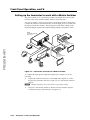
Setting up the Annotator to work with a Matrix Switcher........................... 3-12
Chapter Four • On Screen Annotation............................................................................... 4-1
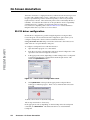
RS-232 Driver Configuration................................................................................................ 4-2
USB Driver Configuration...................................................................................................... 4-2
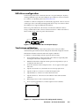
Touchscreen Calibration. ........................................................................................................ 4-2
PRELIMINARY
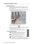
Annotation Overview............................................................................................................... 4-2
Default annotation buttons..................................................................................................... 4-2
Chapter Five • SIS™ Programmer’s Guide........................................................................ 5-1
RS-232/RS-422 Link. .................................................................................................................... 5-2
Ethernet (LAN) Port................................................................................................................... 5-2
Ethernet connection.................................................................................................................. 5-2
Default IP addresses.................................................................................................................. 5-2
Establishing a connection......................................................................................................... 5-2
Connection timeouts.......................................................................................................... 5-3
Number of connections. ........................................................................................................... 5-3
Using verbose mode.................................................................................................................. 5-3
Host-to-Processor Instructions............................................................................................ 5-3
Processor-Initiated Messages.............................................................................................. 5-3
Processor Error Responses. ................................................................................................... 5-4
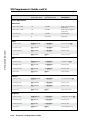
Using the Command/Response Table for SIS Commands................................... 5-4
Symbol definitions..................................................................................................................... 5-4
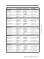
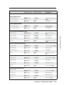
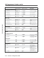
Command/Response Table for SIS Commands.......................................................... 5-8
Chapter Six • Annotator Software....................................................................................... 6-1
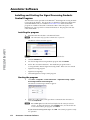
Installing and Starting the Signal Processor Products
Control Program.......................................................................................................................... 6-2
Installing the program.............................................................................................................. 6-2
Starting the program................................................................................................................ 6-2
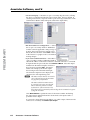
Using the Program. .................................................................................................................... 6-3
Orientation................................................................................................................................. 6-3
Control program menus. .......................................................................................................... 6-4
TOC-ii Annotator • Table of Contents
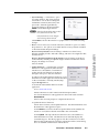
File menu.............................................................................................................................. 6-4
Options menu....................................................................................................................... 6-4
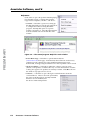
Tools menu. .......................................................................................................................... 6-5
Help menu............................................................................................................................ 6-8
Control tab. ................................................................................................................................ 6-9
I/O Configuration tab.............................................................................................................. 6-10
Advanced Settings tab............................................................................................................ 6-11
Scan Converter tab.................................................................................................................. 6-12
Image Capture tab................................................................................................................... 6-12
Font tab..................................................................................................................................... 6-13
Status bar.................................................................................................................................. 6-13
Chapter 7 • HTML Operation...................................................................................................... 7-1
Accessing the Web Pages....................................................................................................... 7-2
Configuration Pages................................................................................................................. 7-4
System Settings page ......................................................................................................... 7-4
IP Settings fields................................................................................................................... 7-4
Unit Name field............................................................................................................... 7-5
DHCP radio buttons........................................................................................................ 7-5
IP Address field............................................................................................................... 7-5
Gateway IP Address field................................................................................................ 7-5
Subnet Mask field........................................................................................................... 7-5
MAC Address field.......................................................................................................... 7-5
Firmware field................................................................................................................. 7-5
Model field...................................................................................................................... 7-5
Part Number field........................................................................................................... 7-5
Date/Time Settings fields.......................................................................................................... 7-6
Scaler Settings page.................................................................................................................. 7-7
Input configuration........................................................................................................ 7-7
Output configuration..................................................................................................... 7-8
Advanced configuration................................................................................................ 7-8
Passwords page.......................................................................................................................... 7-9
Firmware Upgrade page......................................................................................................... 7-10
File Management Page.......................................................................................................... 7-12
Uploading files......................................................................................................................... 7-12
Adding a directory................................................................................................................... 7-13
Other file management activities. ........................................................................................ 7-13
Control Pages.............................................................................................................................. 7-14
User Control page.................................................................................................................... 7-14
Presets page.............................................................................................................................. 7-15
PIP page. ................................................................................................................................... 7-15
Images Page................................................................................................................................. 7-16
Annotator• Table of Contents TOC-iii
PRELIMINARY
System Status Page................................................................................................................... 7-3
Table of Contents, cont’d
Appendix A • Reference Information. .............................................................................. A-1
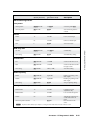
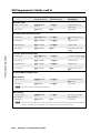
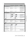
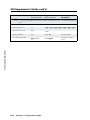
Specifications — Annotator................................................................................................ A-2
Part Numbers, Cables, and Accessories. ...................................................................... A-5
Included parts............................................................................................................................ A-5
Cables. ........................................................................................................................................ A-5
Optional I/O boards.................................................................................................................. A-5
Appendix B • Ethernet Connection......................................................................................B-1
Ethernet Link.................................................................................................................................B-2
PRELIMINARY
Ethernet connection..................................................................................................................B-2
Default address..........................................................................................................................B-2
Ping to determine Extron IP address...................................................................................B-3
Ping to determine Web IP address......................................................................................B-3
Connect as a Telnet client.........................................................................................................B-3
Telnet tips. ..................................................................................................................................B-4
Connecting to an Annotator (Open command).................................................................B-4
Escape character and Esc key...............................................................................................B-4
Local echo.............................................................................................................................B-5
Set carriage return-line feed...............................................................................................B-5
Closing the link to the switcher...........................................................................................B-5
Help.......................................................................................................................................B-5
Exiting Telnet (Quit command)............................................................................................B-5
Subnetting — A Primer. ..........................................................................................................B-5
Gateways.....................................................................................................................................B-5
Local and remote devices.........................................................................................................B-6
IP addresses and octets.............................................................................................................B-6
Subnet masks and octets..........................................................................................................B-6
Determining whether devices are on the same subnet.......................................................B-6
All trademarks mentioned in this manual are the properties of their respective owners.
TOC-iv Annotator • Table of Contents
1
Chapter One
Introduction
About this Manual
About the Annotator
Definitions
Features
PRELIMINARY
Annotator
Introduction
About this Manual
This manual contains installation, configuration, and operating information for the
Extron Annotator. It covers configuring and operating the device using the front
panel controls and Simple Instruction Set (SIS™) commands, and how to annotate
the displayed image. It also describes how to load and start up the Windows®based Signal Processing Products Control Program (SPPCP) and how to connect to
the built-in HTML pages, for operating the processor.
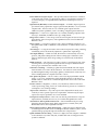
About the Annotator
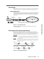
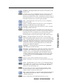
The Extron Annotator, Annotation Graphics Processor, is a scaling product that
allows a presenter to draw, point, or type on video or computer source outputs
using a touch panel, mouse, or keyboard.
PRELIMINARY
Mouse
2
23
RS-
2
23
RSSE
RE
E
US
MO
T
N
LA
B
US
Keyboard
D
OAR
YB
KE
B/ Y
B-
I
DV
OUT
MTP
G/
Y
Y,
-Y,
R/ Y
R-
B-Y
B/R
RG
I/
SD
HD
I
SD
VID
/Y
VID
/Y
B/C
B-Y
3
7
S
V
H
I-D
5
DV
6
4
G/Y
VID
O
U
T
P
U
T
S
C
R/
R-Y
Y
B/C
R-Y
V
1
Extron
Annotator
Y
Y,B-
I
Y,
RN RGB/
P
Y
U 2
BY,Y,
T
RS RGB/
.5A
V Hz
40 /60
0-2 50
V
H/H
Annotator
Touchscreen
X
MA
10
Annotation Graphics
Processor
Projector
Laptop
Video Conference
Codec
Figure 1-1 — Typical Annotator application
1-2
Annotator • Introduction
DVD
Definitions
The following terms are used throughout this manual:
EDID — Extended Display Identification Data. A communications protocol or
instruction set developed by VESA (Video Electronics Standards Association)
for the identification of display devices to computers using the DDC (Display
Data Channel) transmission standard.
DVI — Digital Visual Interface. The digital video connectivity standard that was
developed by DDWG (Digital Display Working Group). This connection
standard offers two different connectors: one with 24 pins that handles digital
video signals only, and one with 29 pins that handles both digital and analog
video. This standard uses TDMS (Transition Minimized Differential Signal)
from Silicon Image and DDC (Display Data Channel) from VESA (Video
Electronics Standards Association). DVI-D is a DVI connector that supports
digital signals only, and DVI-I supports both digital and analog signals.
HD-SDI — High-definition version of SDI specified in SMPTE 292M. This
standard transmits audio and video over a single coaxial cable with a data
rate of 1.485 Gbit/second.
Preset — A configuration that has been stored, allowing the setup and recall of
recurring I/O configurations using either the front panel, RS-232/422, or
Ethernet control.
Input: Up to 128 input presets (individual I/O configurations) may be saved
and recalled. An input preset is a user-defined set of input and picture
control settings that can be saved for each source within a system so that
they can be recalled whenever the source is active. Input presets can be
recalled on any input that supports the saved input’s video format. This
type of preset saves specific settings for size, centering, contrast, brightness,
detail, zoom, and input configuration. Unlike user presets, input presets save
parameters that can be recalled only on the source that was active when the
preset was saved.
User: Up to 16 user presets per input are available. A user preset saves
specific settings for color, brightness, detail, size, and centering. User presets
are used when a shortcut is needed to quickly recall a group of settings that
relate to the current content or current input. Each input has it’s own set of
16 user presets.
Auto Memory — The automatic saving and recall of input and picture controls for
signals that have been previously applied.
Annotator • Introduction
1-3
PRELIMINARY
SDI — Serial Digital Interface. The standard based on a 270 Mbps transfer rate.
This is a 10-bit, scrambled, polarity independent interface with common
scrambling for both component ITU-R 601 and composite digital video and
four channels of embedded digital audio.
Introduction, cont’d
Features
Real time annotations over high resolution PC and video graphics — This allows
a presenter to draw, point, or add text in real time over live video and computervideo presentations.
Inputs: Two RGB or HD component video on 15-pin HD connectors; configurable
input on BNCs for RGB, HD component video, S-video, or composite video;
component video, S-video, or composite video on BNCs; S-video or composite
video on BNCs; DVI-D; and optional SDI/HD-SDI.
Outputs: Simultaneous scaled outputs as RGB or HD component video on BNCs,
15-pin HD, and Extron MTP twisted pair output; optional fourth output for DVID, HD-SDI, or scan-converted component video, S-video, or composite video.
Configurable Preview and Program outputs — The outputs can be configured as
separate Preview and Program outputs. The Preview output allows a presenter
or system operator to view the annotation GUI, while the audience sees the
video and annotation through the Program outputs. This can also be used by the
system operator to preview annotations before making them live.
PRELIMINARY
Hardware-based graphics and video processing — The Annotator features a fully
hardware-based system architecture designed to deliver the performance and
operational reliability essential for mission-critical applications.
Intuitive graphical user interface — A user friendly on-screen display enables
quick and easy annotation. Essential annotation tools are available for drawing
freehand or straight lines, adding rectangular or elliptical shapes, typing in
text, highlighting an area of an image, and pointing to an object on-screen.
Customizing options are available for text and graphics including point size and
color.
Integrated seven-input presentation switcher — The Annotator allows for
switching between DVI, RGBHV, component video, and S-video or composite
video sources. An input for SDI/HD-SDI is available as an option.
Auto input format detection — Each input can be set to detect the incoming signal
format, automatically reconfiguring itself to provide the appropriate decoding
and signal processing. This feature can reduce the number of required outputs
for a device, lowering system cost while improving manageability.
RGB, HDTV, and video scaling — RGB computer-video, high definition video, and
standard definition video sources can be scaled to the desired output resolution.
RGB upscaling and downscaling — The Annotator features an advanced
scaling engine with high quality upscaling and downscaling of high resolution
computer-video signals.
Compatibility with popular touchscreen displays — The Annotator supports
touchscreen displays from third-party manufacturers and also can be used with a
standard keyboard and mouse.
Optional SDI/HD-SDI input — SDI or HD-SDI signals from cameras or other
professional video equipment can easily be integrated into presentations with the
optional SDI/HD-SDI input board.
Four simultaneous annotated video outputs — Two high resolution RGB or
component video outputs are available, as well as Extron MTP twisted pair and
an optional output that can be configured as DVI, HD-SDI, or scan-converted
video.
1-4
Annotator • Introduction
Extron MTP twisted pair output — This provides built-in transmission of RGB or
component video signals over twisted pair cables for long distance transmission
to a remote display. A compatible Extron MTP Series twisted pair receiver is
required.
Optional DVI, HD-SDI, or scan-converted output — A flexible output expansion
port which can be populated to support optional DVI, HD-SDI, or scan converter
output boards. These boards serve as a third Program output and offer
additional system capabilities, such as recording or digital signal transmission.
Output rates — A total of 81 output rates are available, including computer-video
rates up to 1920x1200, and HDTV rates up to 1080p/60 Hz.
Image freeze control — A live image can be frozen using the annotation GUI, the
freeze button on the front panel, or through RS-232 serial control and IP Link®
Ethernet control.
Image capture — A snapshot of the live video output, including annotations, can
be captured and stored as a BMP file on the Annotator or downloaded to a PC for
archiving.
Auto Input Memory — When activated, the Annotator automatically stores size,
position, and picture settings based on the incoming signal. When the same
signal is detected again, these image settings are automatically recalled from
memory.
EDID emulation — The Annotator provides a means for specifying the rate of the
incoming DVI or VGA signal through the RS-232 serial port. EDID emulation
allows proper communication with the video source.
Glitch-free switching — Switching is glitch-free between RGB and video inputs
with selectable cut or fade to black transitions. Presentations can be enhanced
by eliminating distracting visual jumps, glitches, and distortion commonly seen
when switching between computer and video sources.
PIP - picture-in-picture — Allows a video source to be displayed within an RGB
image, or vice versa, with dynamic, fully adjustable window positioning for
the PIP window. PIP mode is available through RS-232 serial control or IP Link
Ethernet control.
Picture controls for brightness, contrast, color, tint, detail, and horizontal and
vertical positioning, sizing, and zoom. Sixteen memory presets are available for
each input to store all image settings.
Aspect ratio conversion — Any video input can be adjusted horizontally and
vertically to meet a specific aspect ratio requirement. Alternatively, the input
aspect ratio may be specified as 4:3 or 16:9 and fixed.
Front panel security lockout — This locks out all front panel functions except for
input selection; all functions however, are available through RS-232 control.
Automatic 3:2 and 2:2 pulldown detection — Advanced film mode processing
techniques help maximize image detail and sharpness for NTSC, PAL, and
HDTV 1080i sources that originated from film.
Motion adaptive 1080i to 1080p deinterlacing — High performance deinterlacing
for 1080i signals from HD sources including broadcasts and Blu-ray Disc™, allows
optimized image quality through advanced motion compensation.
Quad standard video decoding — This uses a digital, four-line adaptive comb filter
to decode NTSC 3.58, NTSC 4.43, PAL, and SECAM video for integration into
systems worldwide.
Annotator • Introduction
1-5
PRELIMINARY
Auto-Image™ — Using the annotation GUI or the front panel, the sizing, centering,
and filtering can be automatically adjusted to optimize the output image.
Introduction, cont’d
IP Link Ethernet monitoring and control — An IP integration technology
developed by Extron. IP Link enables the Annotator to be controlled and
proactively monitored over a LAN, WAN, or the Internet.
RS-232 serial control port — Using serial commands, the Annotator can be
controlled and configured via the Extron Windows-based control program
(SPPCP), or integrated into third-party control systems. Extron products use
the SIS (Simple Instruction Set) command protocol, a set of basic ASCII code
commands that allow for quick and easy programming.
Rack-mountable 1U, full rack width, metal enclosure
PRELIMINARY
Internal universal power supply — The 100-240 VAC, 50-60 Hz, international
power supply provides worldwide power compatibility.
1-6
Annotator • Introduction
2
Chapter Two
Installation
U/L Safety Requirements
Mounting the Annotator
Rear Panel Features and Connections
Powering Up
Resetting the Unit with the Reset Button
PRELIMINARY
Annotator
Installation, cont’d
Installation
UL/Safety Requirements
The Underwriters Laboratories (UL) requirements listed below pertain to the safe
installation and operation of this Annotation Graphics Processor.
PRELIMINARY
Important safety instructions
1.
Read these instructions.
2.
Keep these instructions.
3.
Heed all warnings.
4.
Follow all instructions.
5.
Do not use this apparatus near water.
6.
Clean only with a dry cloth.
7.
Do not block any ventilation openings. Install in accordance with the
manufacturer’s instructions.
8.
Do not install near any heat sources such as radiators, heat registers, stoves,
or other apparatus (including amplifiers) that produce heat.
9.
Do not defeat the safety purpose of the polarized or grounding type plug. A
polarized plug has two blades with one wider than the other. A grounding
type plug has two blades and a third grounding prong. The wide blade or the
third prong are provided for your safety. If the provided plug does not fit into
your outlet, consult an electrician for replacement of the obsolete outlet.
10. Protect the power cord from being walked on or pinched particularly at
plugs, convenience receptacles, and the point where they exit from the
apparatus.
11. Only use attachments/accessories specified by the manufacturer.
12. Use only with the cart, stand, tripod, bracket, or table specified by the
manufacturer, or sold with the apparatus. When a cart is used, use caution
when moving the cart/apparatus combination to avoid injury from tip-over.
13. Unplug this apparatus during lightning storms or when unused for long
periods of time.
14. Refer all servicing to qualified service personnel. Servicing is required when
the apparatus has been damaged in any way, such as power-supply cord
or plug is damaged, liquid has been spilled or objects have fallen into the
apparatus, the apparatus has been exposed to rain or moisture, does not
operate normally, or has been dropped.
2-2
Annotator • Installation
Mounting the Annotator
If the Annotator is to be rack mounted, it is important to mount it before cabling it.
Four rubber feet are included with the unit. Install the feet only if the unit is to be
mounted on a table top (see “Tabletop placement” below).
Tabletop placement
For tabletop placement, install the self-adhesive rubber feet/pads (provided) onto
the four corners of the bottom of the device.
UL guidelines for rack mounted devices
1.
Elevated operating ambient temperature — If installed in a closed or multi-unit
rack assembly, the operating ambient temperature of the rack environment may
be greater than room ambient temperature. Therefore, install the device in an
environment compatible with the maximum ambient temperature
(Tma = +122 °F, +50 °C) specified by Extron.
2.
Reduced air flow — Install the equipment in a rack so that the amount of air flow
required for safe operation of the equipment is not compromised.
3.
Mechanical loading — Mount the equipment in the rack so that a hazardous
condition is not achieved due to uneven mechanical loading.
4.
Circuit overloading — Connect the equipment to the supply circuit and consider
the effect that circuit overloading might have on overcurrent protection and
supply wiring. Appropriate consideration of equipment nameplate ratings should
be used when addressing this concern.
5.
Reliable earthing (grounding) — Maintain reliable grounding of rackmounted equipment. Pay particular attention to supply connections other
than direct connections to the branch circuit (e.g., use of power strips).
Rack mounting
To rack mount the Annotator, insert screws under each opposite corner of the unit
and secure it to the the rack (see figure 2-1).
Rack Mount
Bracket
Figure 2-1 — Mounting the Annotator
Annotator • Installation
2-3
PRELIMINARY
The following Underwriters Laboratories (UL) guidelines pertain to the safe
installation of the Annotator in a rack.
Installation, cont’d
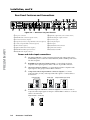
Rear Panel Features and Connections
1
100-240V
2A
50/60 Hz
1
I
N
P
U
T
S
3
R/
R-Y
G/Y
VID
B/C 4
B-Y
VID 5
/Y
VID
/Y
7
HDSDI/SDI
RGB/R-Y,Y,B-Y
2
6
RGB/R-Y,Y,B-Y
2
H/HV
V
R-Y
B-Y
/C
DVI-D
C
5
4
3
12
10
7
G/
Y
R/
R-Y
O
U
T
P
U
T
S
B/
B-Y
LORES
OUT
C
VID
R-Y
R/
Y/
G
17
MOUSE
Y
15
16
LAN
RS-232
RESET
B-Y
B/
USB
H
6
S
V
RGB/R-Y, Y, B-Y
MTP
9
11
8
RS-232
KEYBOARD
13
14
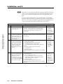
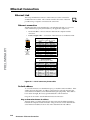
Figure 2-2 — Annotator rear panel features
PRELIMINARY
a AC power connector
b RGB/HD VGA connectors (inputs 1 and 2)
c Universal connectors (input 3)
d Component/S-video/composite BNC connectors (input 4)
e S-video/composite BNC connectors (input 5)
f DVI connector (input 6)
g (Optional) HD-SDI connector (input 7)
h RGB/HD YUV BNC ouput connectors
i RGB/HD VGA output connector
j (Optional) output card (scan converter shown)
k MTP twisted pair output connector
l PS/2 mouse port
m PS/2 keyboard port
n USB A ports
o RJ-45 Ethernet LAN connector
p 9-pin RS-232 connectors
q Reset button and LED
Power and video input connections
a
AC power connector — After connecting all input and output cables, plug a
standard IEC power cord from a 100 to 240 VAC, 50 Hz to 60 Hz power source
into this receptacle.
b
RGB/HD VGA connectors (inputs 1 and 2) — Connect high resolution
computer-video input signals to either of the two 15-pin HD connectors.
c
Universal connectors (input 3) — Connect high resolution computer-video
input signals to this group of female BNC connectors.
d
Composite/S-video/component BNC connectors (input 4) — Connect
composite video, S-video, and component video signals. Connect cables as
shown below.
4
VID
/Y
B-Y
Component Video (Y, R-Y, B-Y)
4
R-Y
/C
B-Y
VID
/Y
R-Y
/C
B-Y
S-video/composite video BNC connectors (input 5) — Connect S-video or
composite video input signals to this pair of female BNC connectors. Connect
cables as shown below.
Composite Video
5
VID
/Y
C
2-4
4
R-Y
/C
VID
/Y
e
S-video (YC)
Composite Video
Annotator • Installation
S-video (YC)
5
VID
/Y
C
DVI-D
f
DVI-D connector (input 6) — Connect a high resolution
input signal to this DVI-D connector.
g
Optional input board (HD-SDI with BNC’s shown) connector (input 7)
— Connect an appropriate input to the optional board connector.
Output, user interface, and control connections
RGB/HD YUV BNC connectors — Connect a display to these for RGB, or HD
YUV component output.
RGsB/Component Video
(Y, R-Y, B-Y)
RGBS/ RGBcvS video
RGBHV
R
/R-Y
G
/Y
B
/B-Y
R
/R-Y
G
/Y
H/
HV
V
S
H/
HV
V
B
/B-Y
S
R
/R-Y
G
/Y
B/
B-Y
H/
HV
V
S
i
RGB/HD 15-pin VGA connector — Connect a display to this for RGB or HD
component video output.
j
Optional output card (scan converter with BNC connectors shown) —
Connect a display to this for composite, S-video, or component video output.
k
l
m
MTP output — Connect a mini twisted pair receiver to this port
n
USB A ports — Connect up to two touch panel devices (or a USB mouse and
keyboard) to these ports.
o
LAN Ethernet port — Connect the Annotator to an Ethernet LAN or WAN
via this RJ-45 connector. Ethernet control allows the operator to control the
processor from a remote location. When connected to an Ethernet LAN or
WAN, the device can be accessed and operated from a computer running a
standard Internet browser. The Link LED lights green when the Annotator
is connected to an Ethernet LAN, and the Act LED flickers amber, indicating
data transmission as the devices communicate.
PS/2 mouse port — Connect a PS/2 mouse to this port for annotation use.
Keyboard port — Connect a Microsoft® compatible keyboard to this port for
annotation use.
N Do not use standard telephone cables, as they do not support Ethernet or Fast
Ethernet. See Appendix B for correct cabling.
Do not stretch or bend cables. Transmission errors can occur.
N See chapter 5, “SIS Programmer’s Guide”, for definitions of the SIS commands
and chapter 6, “Annotator Software” to install and use the control software.
p
Remote (RS-232) 9-pin ports — These connectors provides for two-way
RS-232 communication. See chapters 5 and 6 for information on how to install
and use the control software and SIS commands.
The default protocol is 9600 baud, 1 stop bit, no parity, and no flow control.
q
Ethernet connection indicators — The LEDs marked “Link” and “Act”
indicate the status of the Ethernet connection.
Annotator • Installation
2-5
PRELIMINARY
h
Installation, cont’d
Installation and cabling
Step 1 — Mount the unit
Turn off or disconnect all equipment power sources and rack mount the
Annotator. See page 2-3.
Step 2 — Connect inputs
Connect inputs from video and/or audio sources to the applicable connectors
marked “Inputs” (see page 2-4, b to g for connector types).
N See Appendix B for input and output cabling and connector details.
Step 3 — Connect outputs
Connect audio and video output devices to the applicable I/O board connectors
marked “Outputs” (see page 2-4, h to k for connector types).
Step 4 — Connect user interface devices
PS2 mouse and keyboard ports — Connect a mouse and/or a keyboard for
annotation use.
PRELIMINARY
Step 5 — Connect touch panel devices
USB A ports — Connect a touch panel device as desired.
Step 6 — Connect control devices
LAN Ethernet port — Connect to an Ethernet LAN or WAN via this RJ-45
connector o to control the processor from a remote location, using a PC’s Internet
browser. See Appendix B for network cable termination method. Ethernet
connection indicator LEDs marked indicate the status of the Ethernet connection.
The green LED lights when connected to an Ethernet LAN, and the amber LED
flickers as the devices communicate.
N Do not use standard telephone cables, as they do not support Ethernet or Fast
Ethernet. Do not stretch or bend cables as transmission errors could occur.
Remote ports — For serial RS-232 or RS-422 control, connect a host computer or
control system via the 9-pin D connector p. RS-232 protocol (default values):
• 9600 baud • 1 stop bit • no parity • 8 data bits • no flow control.
N See chapter 5, “SIS Programmer’s Guide” for definitions of the SIS commands. See
chapter 6, “Annotator Software” to install and use the control software.
Step 7 — Connect power
2-6
AC power connector — Plug in a standard IEC power cord from a 100 to 240 VAC,
50 - 60 Hz power source into this receptacle a.
Annotator • Installation
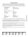
Powering Up
When applying power to the Annotator, the unit undergoes a start-up self testing
sequence (see image below) and then the LCD displays the default display cycle.
Default display cycle
When in use but not in any menu mode, the LCD screen defaults to cycling through
the input/output configuration currently installed. The displayed content may
vary, depending on the input video signal type. See figure 2-3 for a typical default
display cycle.
All buttons flash
in sequence
(green, red, then amber).
10
sec.
Extron
Annotator
v1.xx
= unlit
1
sec.
1
2
MENU
All input buttons
flash consecutively
(amber).
= lit
= flashing
NEXT
Default Display Cycle
1
sec.
1
2
Input #2
60.0kHz
75.0Hz
1
sec.
Last active input
buttons remains lit.
2
sec.
Output Rate
1024x768 60.0Hz
2 sec.
N Th e in p u t a n d o u tp u t r a te s sh ow n
in th e d e fa u lt d isp lay cycle may d iffe r,
d e p e n d in g o n th e typ e o f vid e o sig n a l a ctive.
Figure 2-3 — Typical Default Cycle
The default display cycle shows the output rate and the refresh rates for the
currently selected input.
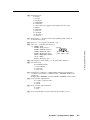
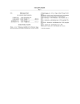
Resetting the Unit with the Reset Button
There are four reset modes (numbered 1, 3, 4, and 5 for the sake of comparison
with Extron IPL products) that you can access by pressing the Reset button on the
rear panel. The Reset button is recessed, so use a pointed stylus, ballpoint pen, or
Extron Tweeker to press it. See the table on the next page for a summary of the
reset modes.
C
The reset modes listed in the table close all open IP and Telnet connections and
close all sockets. Also, each mode is a separate function, not a continuation
from mode 1 to mode 5.
Reset LED flashes once,
twice, or three times.
Modes 3, 4, and 5
Press and hold for
3, 6, or 9 seconds.
RESET
Apply Power
Release, then immediately
press and release again. Reset
LED flashes in confirmation.
RESET
Press and hold
the Reset button.
Release Reset button.
2
1
RESET
Mode 1
RESET
N
Review the reset modes carefully. Using the wrong reset mode may result
in unintended loss of flash memory programming, port reassignment, or
processor reboot.
RESET
Key
3
sec.
Menu and Next
buttons
remain lit.
Figure 2-4 — Resetting the Annotator
Annotator • Installation
2-7
PRELIMINARY
Apply
Power
Installation, cont’d
N After a mode 1 reset is performed, update the Annotators’s firmware to the latest
version. Do not operate the firmware version that results from the mode 1 reset.
If you want to use the factory default firmware, you must upload that version
again.
If you do not want to update firmware, or you performed a mode 1 reset by mistake,
cycle power to the device to return to the firmware version that was running before the
mode 1 reset. Use the 0Q SIS command to confirm that the factory default firmware is
no longer running (look for the asterisk [*] following the version number).
PRELIMINARY
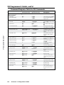
Reset Mode Comparison Summary
Mode
Activation
Result
Notes
1
Hold down the recessed
Reset button while applying
power to the unit.
Mode 1 causes the unit to revert to the factory default
firmware. Event scripting does not start if the unit is
powered on in this mode. All user files and settings
(drivers, audio adjustments, IP settings, etc.) are
maintained.
Use mode 1
to remove
a version of
firmware if
incompatibility
issues arise.
3
Hold down the Reset button
for about 3 seconds, until
the Reset LED blinks once.
Then, within 1 second, press
Reset again briefly (for less
than 1 second).
Mode 3 turns events on or off. During resetting, the Reset
LED flashes 2 times if events are starting; 3 times if events
are stopping.
Events must
be turned on
if you want
to change IP
settings or
scheduling.
4
Hold down the Reset button
for about 6 seconds, until
the Reset LED has blinked
twice (once at 3 seconds,
once at 6 seconds). Then,
within 1 second, press
Reset briefly (for less than 1
second).
Mode 4 does the following:
• Enables ARP capability.
• Sets the IP address back to factory default.
• Sets the subnet back to factory default.
• Sets the default gateway address back to the factory
default.
• Sets port mapping back to factory default.
• Turns DHCP off.
• Turns all events off.
The Reset LED flashes 4 times in quick succession during
reset.
Mode 4 enables
you to set
IP address
information
using ARP
and the MAC
address.
5
Hold down the Reset button
for about 9 seconds, until
the Reset LED has blinked
three times (once at 3
seconds, once at 6 sec., once
at 9 seconds). Then, within
1 second, press Reset briefly
(for less than 1 second).
Mode 5 performs a complete reset to factory defaults
(except the firmware).
• Does everything mode 4 does.
• Resets everything that was set via the Real Time
Adjustments part of the control program: all video
settings and miscellaneous options.
• Resets all IP options.
• Removes/clears all files from the processor.
The Reset LED flashes 4 times in quick succession during
the reset.
Mode 5 is
useful if
you want to
start over
with control
software
configuration
and uploading,
and to replace
events.
2-8
Annotator • Installation
3
Chapter Three
Front Panel Operation
Front Panel Overview
Switching Inputs
Button Backlighting
The Annotator Menu System
Setting the Front Panel Locks (Executive Modes)
Setting up the Annotator to Work with a Matrix Switcher
PRELIMINARY
Annotator
Front Panel Operation
Front Panel Overview
ADJUST
INPUTS
1
2
3
4
5
6
UNDO
/CLEAR
AUTO
IMAGE
SIZE
BRIGHT
/CONT
DETAIL
MENU
CAPTURE
/RECALL
FREEZE
POSITION
COLOR
/TINT
ZOOM
/PAN
NEXT
7
ANNOTATOR
ANNOTATION GRAPHICS PROCESSOR
2
1
3
4
6
5
7
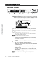
Figure 3-1 — Front panel features
a Front panel configuration port — Connect a control system or computer to this
(RS-232) port, using an optional 9-pin D to 2.5 mm mini jack TRS RS-232 cable,
part 70-335-01 (see below). RS-232 protocol (default values):
• 9600 baud • 1 stop bit • no parity • 8 data bits • no flow control
6 feet
1
6
9
PRELIMINARY
5
Tip
Ring
9-pin D
Connection
TRS Plug
Pin 2
Pin 3
Pin 5
Computer's RX line
Computer's TX line
Computer's signal ground
Tip
Ring
Sleeve
Sleeve (Gnd)
Figure 3-2 — Front 2.5 mm port configuration cable, part 70-335-01
b Input selection buttons — Select/switch inputs and indicate which input is
active.
c Special function buttons — These four buttons are:
• Undo/Clear — Allows a reversal of up to seven of the last annotation
points or clears selected annotations.
N See chapter 4 for an overview of image annotation.
• Auto Image— Allows auto image adjustment on the selected input.
• Capture/Recall — Allows the capture and saving of the current image,
or the recall of a saved image.
• Freeze — Allows the current displayed image to be frozen or unfrozen
as desired.
d Picture control buttons — These six buttons are:
•
•
•
•
•
•
Size — Allows adjustment to the displayed image size.
Bright/Cont — Allows adjustment of the brightness and contrast settings
for the displayed image.
Detail — Allows adjustment of the detail (sharpness) settings for the
displayed image.
Position — Allows horizontal and/or vertical position adjustment of
the displayed image.
Color/Tint — Allows adjustment of the color and tint settings for the
displayed image.
Zoom/Pan — Allows displayed image to be zoomed in or out, or panned
horizontally and/or vertically.
N The above adjustments are made using either or both Adjust knobs.
3-2
Annotator • Front Panel Operation
e LCD display — This LCD screen displays two rows of menu, control response,
and configuration text.
f Menu navigation buttons — These two buttons give access to menu
commands. See “The Annotator Menu System” section in this chapter.
Menu button — This button, always lit amber, gives direct access to a series
of five menus.
Next button — This button, always lit amber, allows page changes within
each one of the menus, and to exit the menu cycle.
g Adjust knobs — These two knobs are used with the picture control buttons and
the menu navigation buttons to adjust settings.
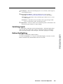
Switching Inputs
Button Backlighting
The buttons can be backlit a dimmed amber.
To turn the backlighting on or off, press and hold the Bright/Cont and Color/Tint
buttons simultaneously until the buttons become lit or unlit.
Annotator • Front Panel Operation
3-3
PRELIMINARY
To switch inputs, simply press the desired input button. The button lights amber
with an active video signal. If the output is configured correctly for the display
device, the image changes to the new input. An inactive signal gives no image.
Front Panel
Operation,
cont’d
Front
Panel
Operation
The Annotator Menu System
The Annotator can be configured using the menu system, via the Extron Simple
Instruction Set (SIS™) of commands through an RS-232 or LAN connected PC, or via
the Extron software program, SPPCP.
N For SIS commands and SPPCP configuration methods see chapters 5 and 6.
The Annotator has six front panel configuration menus: User Presets, Input
Configuration, Output Configuration, Advanced Configuration, View Comm Settings.
A hidden menu (Edit Comm Settings) is also accessible. If the optional Scan Converter
board is installed a scan converter configuration menu becomes available.
User
Presets
Menu
Input
Configuration
Menu
Output
Configuration
Menu
Overview of menus
Advanced
Configuration
Menu
View Comm
Settings
Menu
Exit Menu
Press NEXT
Scan Converter
Configuration
Optional
User Presets
PRELIMINARY
This menu allows the user to save the current image settings to a preset number
(1-16), and recall any saved preset to become the current image settings. Each input
has sixteen user selectable presets.
Input Configuration
This menu allows configuration of the following setting for any selected input:
Input type, Film detection, vertical and horizontal start points, pixel phase, the
number of total and active pixels and the number of active lines, DVI input and
EDID rate (see EDID tables on page 3-6).
Output Configuration
This menu allows configuration of the following settings for the active output:
Resolution and Refresh rate (see table on page 3-6), Output Type, and Sync Polarity
(where applicable).
Advanced Configuration
This menu allows advanced configuration of the following Annotator settings:
Auto Image, Auto Memories, Input EDID, RGB Delay, Switch Effect, Test Pattern,
MTP Pre-Peaking, Internal Temp (view only), Calibrate Panels, and Reset to Factory
defaults.
View Comm Settings
This menu allows the user to view the following serial and IP settings for the unit:
Serial port baud rate, MAC address, DHCP (Dynamic Host Configuration Protocol)
setting, IP address, Subnet Mask address, and Gateway address
N
These settings can not be edited from within this menu. See next section.
Edit Comm Settings (hidden)
To display and enter this menu, press and hold the Detail and Color/Tint buttons
simultaneously and then press Next. The hidden menu appears.
This menu allows the user to edit the following serial and IP settings:
Serial port baud rate, DHCP mode, IP address, subnet mask, and gateway address.
Exit Menu
At this menu pressing Next exits the Menu system and returns to the default cycle.
Scan Converter Configuration
This menu, displayed only when the optional scan-converter board is installed,
allows the user to configure the settings for scan-converted outputs.
3-4
Annotator • Front Panel Operation
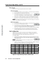
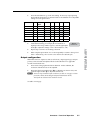
Using the menus
To configure the Annotator using any of the above menus, do the following:
1.
Press the Menu button repeatedly to get to the desired configuration menu.
2.
Press the Next button repeatedly to go to the desired submenu.
3.
The LCD shows the current values. Observe the LCD and rotate either (or
both) adjust knob to change the values as desired.
N Pressing the Menu button within any level takes the user back to the current top
level menu.
Whilst within any menu if for approximately 25 seconds no buttons are pressed
or no adjust knobs rotated, the unit times out and returns to the default cycle.
For individual menu details see the following pages.
Menu
Next
Recall Preset
<NA>
Rotate either to
select a preset to
recall settings.
Next
Save Preset
<02>
Rotate either
to select a preset
to save current
settings to.
Menu
Next
Input #x
RGB
Rotate to select
video input type.
Next
Input #x
Film Detect On
Rotate to turn
Film Detect on
or off.
Next
Input #x
Vert Start 128
Rotate to adjust
Vertical Start value.
Next
Input #x
Horz Start 128
Output
Configuration
Menu
Next
Resol 1024x768
Refresh 60.00Hz
Rotate
to adjust
Resolution value
Rotate to adjust
Refresh rate
Next
Output Type
RGBHV
Rotate either to
adjust Output
type value
Next
Sync Polarity
H Neg
V Pos
Rotate either to
adjust Sync
Polarity values
Rotate to adjust
Horizontal Start value.
Next
Input #x
Pixel Phase 28
Rotate to adjust
Pixel Phase value.
Next
Input #x
Total Pix *2200
Rotate to adjust
Total Pixel value
(* = default).
Next
Input #x
Active Pixels *1920
Rotate to adjust
Active Pixels value
(* = default).
Next
Input #x
Active Lns *1080
Rotate to adjust
Active Lines value
(* = default).
Advanced
Configuration
Next
Auto Image
Input #x
Off
Rotate to turn
Auto Image mode
On or Off
Next
Auto Memories
On
Rotate either to turn
Auto Memories On
or Off
Next
Input EDID
1024x768 60.0Hz
Rotate either to adjust
EDID values
Next
RGB Delay
0.5 Seconds
Rotate either to adjust
RGB Delay value
Next
Switch Effect
Dissolve
Rotate either to
change Switch Effect
Next
Test Pattern
Color bars
Rotate either to
change Test Pattern
Next
MTP Pre-Peaking
Off
Rotate either to turn
MTP Pre-Peaking
On or Off
Next
Internal temp
96 F 35 C
Indicates Internal temperature
(not adjustable)
Next
*N To activate the hidden menu “Edit Comms”,
press and hold Detail and Color/Tint buttons
simultaneously, then press Next.
**N The Scan Coverter Settings menu is only
available when an optional Scan Converter
I/O board is installed.
Menu
Calibrate Panels
Press size
Press Size to callibrate
panel sizes
Next
Reset to Factory
Press Detail
Press Detail to reset unit
to factory settings
View Comm
Settings
Menu
Exit Menu
Press NEXT
Next
Serial Port
9600
RS232
Next
MAC Address
005A6003C24
This is set at the factory
and cannot be changed
in “Edit Comm Settings”
menu.
Next
DHCP Mode
On
Next
IP Address
192.168.254.254
Next
Subnet Mask
255.255.000.000
Next
Gateway Address
000.000.000.000
Optional I/O
Board Menu **
Scan Converter
Settings
Next
H
2048
Size
V
2048
Rotate to adjust
H value. Rotate
to adjust H value.
Next
H Center V
2048
2048
Rotate to adjust
H value. Rotate
to adjust H value.
Next
Output Format
S-video/Comp
Rotate either to
select output format.
Next
“Hidden” Menu *
Edit Comm
Settings
Next
Serial Port
9600
RS232
Rotate to select
RS-232 or RS-422
mode. Rotate to
change baud rate.
Next
DHCP Mode
<On>
Rotate either to turn
DHCP mode On or Off.
Next
IP Address
<192>168.254.254
Rotate
to select
octet field. Rotate
to change address.
Output Standard
NTSC
Rotate either to
select output standard.
Next
Flicker Filter
3
Rotate either to
select output standard.
Next
H Filter
0
Rotate either to
select output standard.
Next
Encoder Filter
0
Rotate either to
select output standard.
Next
Subnet Mask
<255>255.000.000
Rotate
to select
octet field. Rotate
to change address.
Next
Gateway Address
<000>000.000.000
Rotate
to select
octet field. Rotate
to change address.
Annotator • Front Panel Operation
3-5
PRELIMINARY
User
Presets
Input
Configuration
Front Panel Operation, cont’d
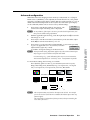
User presets
Within this menu up to 16 presets can be saved or recalled.
Save a user preset
1.
From the default display cycle press Menu to enter the User Presets submenu.
2.
Press Next twice to go to the Save Preset menu.
3.
Save Preset
Rotate either front panel encoder to select a preset (1 to 16)
<N/A>
to save the current settings to. Default setting is <N/A>.
Select <N/A> and press Next to move to the next submenu without saving.
4.
Press Next to save the current image settings to the selected Preset number.
The Preset is saved and the LCD goes back to the top level User Preset menu.
N If an existing Preset is chosen to save to, the previous settings are overwritten in
favor of the new (current) settings.
PRELIMINARY
Recall a user preset
1.
From the default display cycle press Menu to enter the User Presets submenu.
2.
Press Next to go to the Recall Preset menu.
3.
Rotate either front panel adjust knobs ([{) to select a preset
(1 to 16) to recall as the current settings. Default setting is N/A.
Select <N/A> and press Next to move to the next submenu without recalling.
4.
Press the Next button. The Preset is recalled, the image changes to the
recalled settings and the LCD goes back to the top level User Preset menu.
Recall Preset
<02>
Input configuration
Within this menu any of the seven inputs can be configured. Each input has
different settings depending on the signal format. Consult the tables below for
signal formats per input and possible adjustments per signal format.
To configure inputs:
1.
From the top level Input Configuration menu press the Next button to bring
up the input selection screen. The active input is displayed on the LCD with
current signal format.
Input #2
N If the input showing is not the one to be adjusted, press the
desired input button.
2.
Input #1
With the correct input displayed, rotate the right adjust knob ({) to change the
signal format (refer to table below for signal type per input).
Input #2
Input #3
Input #4
Input #5
Input #6 Input #7
*DVI
*RGB
*RGB
*RGB
*YUVi
*S-Video
YUVp/HDTV
YUVp/HDTV
YUVp/HDTV
S-Video
Composite
HD-SDI
Auto Detect
Auto Detect
RGBcvS
Composite
Auto Detect
Auto Detect
YUVi
Auto Detect
S-Video
Composite
Auto Detect
Figure 3-3 — Signal formats per input (*= default value)
3-6
YUVp/HDTV
Annotator • Front Panel Operation
*SDI
Press the Next button to go to the next setting. If necessary repeat pressing
Next until the desired level is attained. Refer to the table below for adjustable
settings for each signal format.
Input Format
RGB
YUVp/
HDTV
RGBcvS
YUVi
S-vid
SDI
HD-SDI
Film Detect
X
X
X
X
X
X
X
H Start
X
X
V Start
X
X
Pahse
X
X
Total Pixels
X
X
Active Pixels
X
X
X
X
X
X
X
Active Lines
X
X
X
X
X
X
X
Figure 3-4 — Adjustments possible per signal format
4. At the desired setting (for example, Horizontal Start on
input #2 with a YUVp/HDTV signal), rotate the right adjust
knob ({) to adjust the settings value as desired (here to 122).
Input #2
Horz Start 122
5.
Repeat steps 3 and 4 for each setting as desired.
6.
When complete press Menu once or Next repeatedly to return to the top level
menu. Alternatively, allow to time out to return to the default cycle.
Output configuration
Within this menu an outputs resolution, refresh rate, output signal type, and sync
polarity can be selected and adjusted. Refer to the table below for applicable
resolution and refresh rates.
1.
Press Next to bring up the Resolution submenu. In this submenu, the
resolution and refresh rate can be adjusted.
Rotate the left front panel encoder ([) to adjust the resolution value, and
rotate the right encoder ({) to adjust the refresh rate.
N There are 25 pre-installed output resolutions (see table on next page) to choose
from (640 x 480 at 50 Hz through 1080p and 2048x1080 at 60 Hz).
The refresh rate is based on the resolution selected.
2.
See table on next page.
Annotator • Front Panel Operation
3-7
PRELIMINARY
3.
Front Panel Operation, cont’d
PRELIMINARY
Resolution
23.98 Hz
24 Hz
25 Hz
29.97 Hz
30 Hz
50 Hz
59.94 Hz
*60 Hz
75 Hz
640x480
X
X
X
800x600
X
X
X
852x480
X
X
X
1024x768
X
X
X
1024x852
X
X
X
1024x1024
X
X
X
1280x768
X
X
X
1280x800
X
X
X
1280x1024
X
X
X
1360x765
X
X
X
1360x768
X
X
X
1365x768
X
X
X
1366x768
X
X
X
1365x1024
X
X
X
1440x900
X
X
X
1400x1050
X
X
1680x1050
X
X
1600x1200
X
X
1920x1200
X
480p
576p
X
X
X
X
X
X
X
X
X
X
720p
X
X
X
X
1080i
X
1080p
X
X
X
X
X
X
X
X
X
2048x1080
X
X
X
X
X
X
X
X
X
Figure 3-5 — Output resolution/refresh rate table
3.
Press Next to enter the next submenu, Output Type. Within this submenu the
output signal type (RGBHV, RGsB, YUV Bi-Level, or YUV Tri-Level) can be
selected.
4.
Rotate either front panel adjust knob ([{) to select the output signal type.
5.
Press Next to enter the next submenu, Sync Polarity. Within this submenu,
the Sync Polarity can be set (H- V-, H+ V-, H+ V+, or H- V+).
6.
Rotate either front panel adjust knob ([{) to select the sync polarity.
N An incorrect sync polarity setting will result in the loss of the output image.
7. Press Next or Menu to return to the Output Configuration.
3-8
Annotator • Front Panel Operation
Advanced configuration
Within this menu auto imaging and auto memory can be turned on or off, Input
EDID can be set, RGB delay value adjusted, the switch effect chosen, a test pattern
selected to aid setting up the display, and the MTP pre-peaking turned on or off. In
addition the internal temperature can be read, the size of the touch panel display
can be calibrated, and the unit can reset to factory default settings.
1.
Auto Image
Input #2 On
Press Next to enter the first sublevel, Auto Image. The
current active input and setting status is displayed.
2.
With the applicable input showing, rotate the right adjust knob ({) to turn the
Auto Image on or off.
3.
Press Next to enter the next sublevel, Auto Memory and rotate either adjust
knob ([{) to turn the Auto Memory on or off.
4.
Press Next to go to the next sub-level (Input EDID), or press Next repeatedly
to get to any applicable level. At each level, rotate the
Input EDID
adjuster knobs (right only or both)
1024x768 60.0Hz
as needed to change the settings to the desired value.
N The Input EDID setting adjustment applies only to the VGA and DVI inputs.
Refer to figure 3-5 for resolution and refresh rate details.
For some settings (e.g., panel calibration) follow any on-screen instructions.
The internal temperature is a “read-only” screen. No adjustment is possible.
For Test Pattern settings, the following are available:
None (default), Split Color Bars (8), Crosshatch 4x4, 32 Level Grayscale,
Ramp, Alternating Pixels, Whitefield, Crop, 1.33 Aspect ratio, 1.78 Aspect
ratio, 1.85 Aspect ratio, 2.35 Aspect ratio, Safe Area, Blue Mode.
N
Color Bars
Crosshatch
Alternating
Pixels
White Field
Crop
1.33 Aspect
1.85 Aspect
2.35 Aspect
Safe Area 5% 10%
4x4 Crosshatch Split Grayscale
Ramp
1.78 Aspect
The test patterns may vary based on the output rate selected. For example
if a 4:3 rate is selected, then the 4:3 crosshatch (32x24) and aspect ratio crop
patterns appear.
The raster border is independent of the aspect ratio, always surrounding the
active area of the screen.
Annotator • Front Panel Operation
3-9
PRELIMINARY
N At any submenu, if the input is incorrect, press the desired input button, and
then proceed with the setting adjustment.
Front Panel Operation, cont’d
If a touch panel screen is attached to the Annotator, the touch accuracy can be
calibrated using the Calibrate Panels setting in the Advanced configuration menu.
1.
Within the Advanced configuration menu press Next repeatedly to cycle to
the Calibrate Panels submenu.
2.
Press the Size button and observe the touch panel screen. A cross appears in
the upper left corner. Tap the screen at the cross, and repeat at each cross.
3.
After tapping the fourth cross, the unit saves the calibration data and restarts
the sequence. Repeat the process for each connected touch screen.
4.
Press any front panel button to exit the sequence and save the data.
N See page 4-2 for detailed touchscreen setup instructions.
View comm settings
PRELIMINARY
Within this menu the current IP settings are only viewable. To make any
adjustments the hidden “Edit Comm Settings menu must be accessed (see below).
1.
Press Next to go through each sub-level to view the following: Serial port
(baud rate and communication type), MAC address (cannot be changed
within the Edit Comm menu), DHCP status (on or off), IP address, Subnet
mask, and Gateway address.
2.
Press Next or Menu to return to the View Comm Settings menu.
To enter the “hidden” Edit Comms menu, press and hold in the Detail and
Color/Tint buttons simultaneously, and then press the Next button. The Edit
Comms menu appears.
Edit comm settings
1.
Press Next to go through each sublevel to edit the following: serial port
settings, DHCP (on or off), IP address, subnet mask, and gateway address.
N The hardware address (the MAC address) is hard coded and cannot be changed.
In edit mode the MAC address menu is not displayed.
2.
At each level, use both adjust knobs to set new values as desired. For example
rotate the left front panel Adjust knob ([) to adjust the baud rate (9600,
19200, 38400, or 115200), and rotate the right Adjust knob ({) to select the
connection type (RS-232/RS-422).
N For IP address, subnet mask, and gateway address settings, the left Adjust knob
moves between octets and the right Adjust knob changes the values.
Where already connected to a remote PC via LAN, changing the IP address can
result in the loss of connection.
The device’s default IP address is 198.162.254.254.
3.
Press Next or Menu to exit the Edit Comm Settings menu, keeping the new
settings.
Exit menu
Within this menu press Next to exit the menu system and return to the default
display cycle.
3-10
Annotator • Front Panel Operation
Scan converter configuration
This menu is available only when a scan converter board is installed.
1.
Press Next to enter the first sublevel, horizontal and vertical size. The current
settings are displayed. (2048 is the default setting)
2.
Rotate the left front panel adjust knob ([) to adjust the horizontal value, and
rotate the right adjust knob ({) to adjust the vertical value.
3.
Press Next to go the second sublevel, horizontal and vertical centering.
4.
Rotate the left front panel adjust knob ([) to adjust the horizontal value, and
rotate the right adjust knob ({) to adjust the vertical value.
5.
Press Next to go to the next sub-level (Output Format), or press Next
repeatedly to get to any level. At each level, rotate either adjuster knobs as
needed to change the settings to the desired values:
Output format (S-video/Comp, YUVi, or RGsB)
Output Standard (NTSC or PAL)
Flicker, Horizontal, and Encoder filter values (0 to 3)
6.
When complete press Menu once or Next repeatedly to return to the top level
menu. Alternatively, allow to time out to return to the default cycle.
Setting the Front Panel Locks (Executive Modes)
The Annotator has two levels of front panel security lock that limit the operation
of the device from the front panel.
Executive mode 0 (disabled) — The front panel is fully unlocked. This is the
default setting.
Executive mode 1 (enabled) — The front panel is locked except for input switching,
video freeze, and auto image.
Executive mode 2 (enabled) — The front panel is completely locked. This
mode can only be enabled and disabled using SIS commands. See chapter 5 SIS
Commands for further details.
Enabling or disabling Executive mode 1 from the front panel
N If the Annotator is in Executive mode 0 (unlocked), this procedure selects mode 1
(locked).
If it is in Executive mode 1, this procedure selects mode 0 (unlocks the unit).
Press and
hold for about
2 seconds.
SIZE
BRIGHT
/CONT
DETAIL
POSITION
COLOR
/TINT
ZOOM
/PAN
LCD screen
displays either
Executive Mode
Enabled
OR
Executive Mode
Disabled
Figure 3-6 — Turning Executive mode on or off
When either Executive mode is enabled and a front panel action is attempted (other
than input switching, video freeze, and auto image), the LCD displays the status for
2 seconds.
Lock mode 1 can also be enabled or disabled by SIS commands. See chapter 5 for
SIS commands.
Annotator • Front Panel Operation
3-11
PRELIMINARY
Within this menu horizontal and vertical image size and centering can be
configured, output format and output standard chosen, and flicker, horizontal, and
encoder filters set.
Front Panel Operation, cont’d
Setting up the Annotator to work with a Matrix Switcher
The Sync to Matrix tool is a powerful tool which can simplify the control system
necessary when using an Extron Matrix switcher and an Annotator.
The “Sync to Matrix” script can sense when a new tie that is made on the matrix is
routed to the Annotator and automatically recalls the input preset associated with
the input on the matrix switcher. The input preset recalls all the settings for the
input including the signal format, input sampling settings, and picture controls.
Extron
CrossPoint 300 84 HV
Matrix Switcher
ST
ADJU
OU
4
TP
UT
S
3
TORR
OTAESSO
ANN
S PROC
U
MEN
T
PHIC
N GRA
SE
RE
NEXT
TATIO
ANNO
LAN
2
1
R
IL
DETA
HT
BRIG T
/CON
G
SIZE
AUTOE
IMAG
B
UNDO
AR
/CLE
7
H
INP
6
S
UT
7
8
4
ZOOM
/PAN
4
3
2
B
Extron
Annotator
1
C
C
H
R
COLO
/TINT
ER
CENT
ZE
FREE
5
V
G
3
2
URE
CAPT LL
/RECA
6
TS
INPU
R
5
IG
CONF
V SYN
H SYN
1
V
Annotation Graphics
Processor
ST
ADJU
TORR
OTAESSO
ANN
S PROC
U
MEN
PHIC
N GRA
PRELIMINARY
DVD/VCR
NEXT
TATIO
ANNO
IL
DETA
HT
BRIG T
/CON
SIZE
AUTOE
IMAG
UNDO
AR
/CLE
7
URE
CAPT LL
/RECA
R
COLO
/TINT
ZOOM
/PAN
ER
CENT
ZE
FREE
6
TS
INPU
5
4
3
Display
2
1
IG
CONF
Extron
Annotator
AV Tuner
Camera
Annotation Graphics
Processor
HD Tuner
Extron
RGB 109xi
Interface
Document
Camera
Display
PC
Figure 3-7 — Annotators connected to a Matrix switcher
To configure the input presets required using the Sync to Matrix tool, do the
following:
1.
Install and connect the Annotator as described in the chapter two of this
manual, but connect the Annotator’s input 3 to one of the matrix switcher’s
outputs.
N Multiple Annotators can be connected to a single matrix switcher.
2.
3-12
Tie input 1 of the matrix switcher to whichever matrix switcher output is
connected to input 3 of the Annotator (see figure 3-8).
Annotator • Front Panel Operation
Input 1
Output 1
Input 3
Annotator #1
Output to display
Input 2
Output 2
Input 3
Annotator #2
Output to display
Input 3
Output 3
Input 4
Output 4
Input 5
Output 5
Input 3
Annotator #6
Output to display
Input 6
Matrix
Switcher
Output 6
(optional)
(optional)
Output 3
Output 4
Figure 3-8 — Multiple Annotator’s connected to a Matrix switcher
3.
On the Annotator, configure the input as follows:
a). Switch to input 3 on the Annotator.
b). Set the following input sampling settings as needed: signal type,
horizontal and vertical start, pixel phase, total pixels, active pixels, and
active lines
N Do not use auto detect setting for the input type when using input presets.
c). Set the following picture controls as needed: size, position, color, tint,
brightness, contrast, and detail.
d). Save the adjusted settings as input preset 1. Refer to chapter 5,
“Programmers Guide”, for the SIS commands to save the preset.
N Each input preset must be saved with the same number as the input on the
matrix switcher. For Example, input 24 on the matrix will be associated with
the input preset 24 on the Annotator.
e). Repeat steps 2 and 3 for each matrix input that is used on the Annotator.
4.
Synchronize the Annotator to the matrix switcher as follows:
a). Open the control program (SPPCP) and connect to the Annotator.
N Connection must be via IP (not RS-232).
b). From the Tools menu, select Sync to
Matrix Switcher... . The Sync to Matrix
Switcher window opens
c). In the IP Address field, enter the matrix
switcher’s IP address.
d). Click Connect to Matrix button. The
matrix switcher’s size is displayed.
e). From the drop-down menu next to
Annotator Input #3 select the matrix
output number that is connected to Input 3 on the Annotator. Click Take.
The devices now sync.
Annotator • Front Panel Operation
3-13
PRELIMINARY
Input 64
4
Chapter Four
On Screen Annotation
RS-232 Driver Configuration
USB Driver Configuration
Touchscreen Calibration
Annotation Overview
PRELIMINARY
Annotator
On Screen Annotation
The Extron Annotator is a high performance, hardware-based annotation processor
for video and computer-video sources. Annotating over motion video or still
images is possible using common touchscreen panels, as well as any standard
keyboard and/or mouse. The touchscreen panels can be connected by RS-232 or
USB hubs. A touchscreen device driver can be uploaded to ensure compatibility
with the Annotator. A number of touchscreen panels are supported.
For a full list of compatible panels visit www.extron.com. Contact the Extron
HelpLine if the device you wish to use in not listed.
RS-232 driver configuration
RS-223 driver configuration is possible using the Signal Processing Products
Control Program. The Touch Screen Panel Configuration option allows you to
configure a touchpanel so that it can be used with the Annotator.
Using a NULL RS-232 cable only, connect the touchscreen to the Annotator via
either of the two rear panel RS-232 comm ports.
PRELIMINARY
To configure a touchpanel for use with the Annotator:
1.
Open the SPPCP program on a connected PC
2.
From the Tools menu, select RS-232 Touch Screen Panel Configuration. This
opens the Touch Screen Configuration window.
3.
In the appropriate section, depending on which COM port has a touchpanel
connected, select the type of touchpanel from the drop-down list. This
enables the Upload Driver button.
Figure 5-1 — Touch Screen Configuration screen
4.
Click Upload Driver. This uploads the appropriate touchpanel driver
A dialog box indicates progress. The box closes when the driver has been
uploaded.
To delete a driver from an attached touchpanel:
Follow steps 1 and 2 above if necessary.
In the appropriate section, depending on which COM port has the touchpanel
connected, click Delete Driver. This deletes the driver associated with the
touchpanel.
4-2
Annotator • On Screen Annotation
USB driver configuration
Touch screen panels can be connected via the two rear panel USB ports. By daisy
chaining USB hubs (3 per Annotator USB port) up to 20 devices can be connected.
For a full list of compatible panels visit www.extron.com.
A number of common touchpanels are automatically supported. A mix of size and
vendor type can be connected, but unsupported devices may cause adverse affects.
The USB ports also support USB keyboards and mice.
Before use, panel calibration is advised (see ”Touchscreen calibration” below).
Using a suitable USB A cable, connect a touchscreen device or hubs to the either of
the two USB A ports on the rear panel of the Annotator.
Annotator
USB #1
1 2 3 4
Hubs
1 2 3 4
1 2 3 4
1 2 3 4
1 2 3 4
Figure 5-1 — Connect USB hubs for multiple displays
Touchscreen calibration
If a touchscreen is attached to the Annotator, the touch accuracy should be
calibrated using the Calibrate Panels setting in the Advanced configuration menu.
Both RS-232 and USB connected touchscreens require calibration.
To calibrate a connected and powered-on panel, do the following:
1.
Press the Menu button on the front panel of the Annotator repeatedly until
reaching the Advanced Configuration menu.
2.
Within the Advanced configuration menu press Next repeatedly to cycle to
“Calibrate Panels Press Size”.
3.
Press Size and observe the touchpanel screen. A cross appears in the upper
left corner.
4.
Tap the screen at the cross, which then moves to the top right corner.
5.
Tap the second cross. This moves to the bottom right corner.
6.
Tap the third cross. This moves to the bottom left corner.
7.
Tap the fourth cross. The unit saves the calibration data and restarts the
sequence.
8.
Repeat the process for each connected touchscreen.
9.
Press any front panel button to exit the sequence and save the data.
1
4
2
3
Figure 5-1 — Sequence of crosses for setting touch accuracy
Annotator • On Screen Annotation
4-3
PRELIMINARY
On Screen Annotation, cont’d
Annotation Overview
The Annotator's output has the capability to include a graphical tool bar which
is used for annotation. The tool bar can be enabled or disabled as desired. When
enabled, the tool bar is visible down the right side of the display and allows
selection of the following:
PRELIMINARY
Inputs selection, Pointer, Auto Image, Freehand, Line, Arrow, Rectangle Ellipse,
Text, Highlighter, Size select, Eraser, Color, Fill, Undo, Redo, Clear, Tools; Capture,
Freeze, Mute, Whiteboard, Spotlight, Zoom, and Pan.
Figure 5-2 — Annotation menu examples
When clicking on the tool bar arrow
, the tool bar slides in from the
right side, and can be accessed through a touch screen, or by using a Microsoft®
compatible mouse and/or keyboard attached to the rear PS/2 ports.
The tool bar disappears (hides) after a user-specified time-out.
If the time-out is set to zero, the tool bar remains on-screen indefinitely.
Default annotation buttons
Input selection — Selecting this button opens a pop-up
palette displaying the Annotator's six inputs. Selecting any
input button switches the display to that input.
N A seventh input button is also displayed if an optional HD-SDI card
is installed.
4-4
Pointer — Selecting this button changes the cursor to an
extra-large arrow of the currently selected color.
Auto-Image™ — On selection of this button, the unit performs an
auto image on the currently selected input. A secondary button appears
to the left of the Auto Image button to confirm the function has been
completed.
Annotator • On Screen Annotation
Freehand — Selecting this button allows the user to draw freely on the
display screen.
N For Freehand, Line, Arrow, and Highlighter functions, the start point is where
the screen is touched (by finger or stylus), or where the cursor starts when
holding down the primary mouse button. The finish point is where the stylus or
finger is lifted from the screen, or at the point where the mouse button is released.
Line — Selecting this button allows the user to create a straight line
between two points.
Arrow — Selecting this button allows the user to create a straight line
between two points with an arrow at the end point.
Rectangle — Selecting this button allows the user to create a rectangle
with edges parallel to the raster.
N For Rectangle and Ellipse functions, the primary corner is where the screen is
first touched (by finger or stylus), or where the cursor starts when holding down
the primary mouse button. The opposite corner is where the stylus or finger is
lifted from the screen, or at the point where the mouse button is released.
Unless the fill option is selected, only the rectangle or ellipse outline is drawn.
Ellipse — Selecting this button allows the user to create an ellipse
between the primary and the opposite corners of a non-drawn rectangle.
Text — Selecting this button allows the user to create on-screen text with
a keyboard connected at the Annotator's rear PS2 port. Text insertion
begins either at the mouse operated cursor point, or where the screen is
touched. If no insertion point is defined, then text is inserted at the
previous active function's end point.
Highlighter — Selecting this button allows the user to highlight the
video information, not the annotation.
Size Select — Select this button to adjust size of text and/or line weight
(not linked), after selecting a drawing or text function, such as line,
rectangle, or text. A secondary palette opens displaying either line
weight or text point size depending on the active function. From the
secondary palette select the desired size button. Functions this applies
to are Text, Line, Arrow, Freehand, Highlighter, Arrows, Rectangle,
Ellipse, and Eraser.
N Eraser size, text size, and line weight have discrete size settings.
Eraser — Select this to erase any (non saved) annotations on the screen.
Color — Select this button to choose the color of any drawing function
(fill or outline), text, or pointer color. On selection, a secondary palette
opens with 16 color swatches. Select a color as desired. The active
function now uses the selected color.
N The current active color is shown on the Color button as the large swatch.
64 colors are definable via SIS™ commands, although the OSD (On Screen
Display) only shows 16 of the most common colors.
Fill — Selecting this button in conjunction with selecting the rectangle or
ellipse button, allows the user to draw a solid shape, filled with the
currently selected color.
N A drawn, unfilled shape cannot be filled afterwards, and vice versa.
Annotator • On Screen Annotation
4-5
PRELIMINARY
For all drawn annotations, line color and weight are adjustable.
On Screen Annotation, cont’d
Undo — Selecting this allows the user to undo the last 7 completed
annotations or undo a Clear action.
N A completed annotation is defined by lifting the finger or stylus from the touch
screen, pressing the keyboard Enter key, or releasing the primary mouse button.
Redo — If selected while using the Undo function, it recreates the last
undone annotation.
Clear — Selecting this clears the screen of all unsaved annotations, and
can be undone with the Undo function.
Tools — Selecting the Tools button opens a secondary palette containing
the following advanced tools: Capture, Freeze, Mute, Whiteboard,
Spotlight, Zoom, and Pan. On selection of any tool, the secondary
palette closes. To reopen the palette, click on the Tools button.
Capture — Select this to take a snapshot image of the current program
output, including annotations (but not any open OSD palettes). This
captured image can be saved to the Annotator's memory for later recall.
PRELIMINARY
N Using SIS commands the Capture tool can be customized to send out an
unsolicited response, indicating an image is ready to be streamed directly to an
external PC.
4-6
Freeze — Select this to freeze the live video. To unfreeze the video,
reselect this button or switch inputs.
Mute — Select this to mute the video input and display a black screen.
Annotations and menus are still visible. To unmute the video, reselect
the Mute button, or select the Whiteboard tool, or switch inputs.
Whiteboard — Select this to create a white canvas for annotations. No
input video image is visible. To remove the white canvas, reselect the
Whiteboard button, select mute, or switch inputs.
Spotlight — Select this to create an ellipse to focus on a specific area of
the screen, while the outer area's brightness is greatly reduced. The
shape and size of the ellipse is adjustable by dragging the cursor while
outside of it, to any point. The ellipse can be moved to any point by
dragging the cursor while within the ellipse.
Zoom — Select this to zoom in to a specific area of the screen. Using the
cursor, create a rectangle at the desired area and the Annotator zooms in
to view that area. If the boundaries of the area are beyond the zoom
capabilities, then the view will not change. To zoom out draw a small
rectangle (<100 pixels, ~1"x 1") and the normal view is restored.
Pan — Selecting this while in zoom mode, allows the user to move the
focus to a new area. Place the cursor on a zoomed image and drag to
the desired area.
Annotator • On Screen Annotation
5
Chapter Five
SIS™ Programmer’s Guide
RS-2323/RS-422 Link
Ethernet (LAN) Port
Host-to-Processor Instructions
Processor-Initiated Messages
Processor Error Responses
Using the Command/Response Tables for SIS commands
Command/Response Table for SIS Commands
PRELIMINARY
Annotator
SIS Programmer’s Guide
The Annotator can be operated and configured using Simple Instruction Set (SIS™)
commands input via a PC connected to either of the processor’s serial ports or the
Ethernet port. See o and p on page 2-4, and Appendix B for wiring details.
RS-232/RS-422 Link
The Annotator has two rear ports and one front port that can be used for serial
control. All ports enable use of SIS commands and the Windows-based control
software. The default protocol for these ports is:
• 9600 baud, • 1 stop bit, • no parity, • no flow control, • 8-bit.
See p on pages 2-4 through 2-5 for connection details.
Ethernet (LAN) Port
PRELIMINARY
The rear panel Ethernet connector on the unit can be connected to an Ethernet
LAN or WAN. Communications between the unit and the controlling device is via
Telnet (a TCP socket using port 23). The TCP port can be changed if necessary. This
connection makes SIS control of the unit possible using a computer connected to
the same LAN or WAN. The SIS commands and behavior of the unit are identical
to that when communicating to it via RS-232.
Ethernet connection
The Ethernet cable can be terminated as a straight-through cable or a crossover
cable and must be properly terminated for your application. See Appendix B for
cable termination details.
Default IP addresses
To access the Annotator via the Ethernet port, you need the Extron IP address and
may need the subnet mask and the gateway address. If the IP address has been
changed to an address comprised of words and characters, the actual numeric IP
address can be determined using the ping (ICMP) utility (see Appendix B for more
details). If the addresses have not been changed, the factory-specified defaults are:
IP address: 192.168.254.254, subnet mask: 255.255.0.0, gateway address: 0.0.0.0
Establishing a connection
Establish a network connection to the processor as follows:
1.
Open a TCP socket to port 23 using the processor’s IP address.
N If the local system administrators have not changed the value, the factoryspecified default, 192.168.254.254, is the correct value for this field.
The processor responds with a copyright message including the date, the
name of the product, firmware version, part number, and the current date/
time.
N If the processor is not password-protected, the device is ready to accept SIS
commands immediately after it sends the copyright message.
N If the processor is password-protected, a password prompt appears below the
copyright message.
5-2
2.
If the processor is password protected, enter the appropriate administrator or
user password.
If the password is accepted, the processor responds with Login User or
Login Administrator.
If the password is not accepted, the Password prompt reappears.
Annotator • SIS Programmer’s Guide
Connection Timeouts
The Ethernet link times out after a designated period of time of no communications.
By default, this timeout value is set to five minutes but the value can be changed.
See the “Global configure IP port timeout” command on page 5-xx.
N Extron recommends leaving the default timeout at five minutes and periodically
issuing the Query (Q) command to keep the connection active. If there are long
idle periods, Extron recommends disconnecting the socket and reopening the
connection when another command must be sent.
Number of connections
The Annotator can have up to 200 simultaneous TCP connections, including all http
sockets and Telnet connections. When the connection limit is reached, the processor
accepts no new connections until some have been closed. No error message
or indication is given that the connection limit has been reached. To maximize
performance of an IP Link device, the number of connections should stay low and
unnecessary open sockets should be closed.
Telnet connections to the processor can be used to monitor for changes that occur
on the processor, such as front panel operations and SIS commands from other
Telnet sockets or a serial port. For a Telnet session to receive change notices from
the processor, the Telnet session must be in verbose mode 1 or 3. See the Verbose
Mode command on page 5-xx. In verbose mode 1 or 3, the Telnet socket reports
changes in messages that resemble SIS command responses.
Host-to-Processor Instructions
SIS commands consist of one or more characters per command field. They do not
require any special characters to begin or end the command character sequence.
Each processor response to an SIS command ends with a carriage return and a line
feed (CR/LF = ]), which signals the end of the response character string. A string
is one or more characters.
Processor-Initiated Messages
When a local event such as a front panel operation occurs, the processor responds
by sending a message to the host. The processor-initiated messages are listed
below.
With an RS-232/422 connection (upon power up):
(c) Copyright 2009, Extron Electronics Annotator, Vx.xx, 60-968-14]
With an Internet connection:
(c) Copyright 2009, Extron Electronics Annotator, Vx.xx, 60-968-14]
Ddd, DD MMM YYYY HH:MM:SS (day, date time. e.g. Tue, 14 Apr 2009 14:43:17)
The processor initiates the copyright message when powered on or when
connection via Internet protocol (IP) is established. Vx.xx is the firmware version
number.
]Password:
The processor initiates the password message immediately after the copyright
message when the controlling system is connected using TCP/IP or Telnet and the
processor is password protected. The processor requires an administrator or user
level password before performing the commands entered.
N Password prompt is re-displayed if an incorrect password is entered.
]Login Administrator] and ]Login User]
The processor initiates the login message when a correct administrator or user
password has been entered. If the user and administrator passwords are the same,
the processor defaults to administrator privileges.
Annotator • SIS Programmer’s Guide
5-3
PRELIMINARY
Using Verbose Mode
SIS Programmer’s Guide, cont’d
Reconfig]
The processor sends the Reconfig message whenever a new resolution is applied.
N Response given seen via RS-232 connection only.
Exen]
The processor initiates the Exe message when executive mode is toggled on or off
from the front panel. “n” is the executive mode status: 1 = on, 0 = off.
Processor Error Responses
When the Annotator receives an SIS command and determines that it is valid, it
performs the command and sends a response to the host device. If the processor
is unable to perform the command because the command is invalid or contains
invalid parameters, the processor returns an error response to the host. The error
response codes are:
PRELIMINARY
E01 — Invalid input channel number (out of range)
E10 — Invalid command
E11 — Invalid preset number
E12 — Invalid output number/port number
E13 — Invalid parameter (out of range)
E14 — Command not available for this configuration
E17 — Invalid command for this signal type
E22 — Busy
E24 — Privilege violation
E25 — Device not present
E26 — Maximum number of connections exceeded
E27 — Invalid event number
E28 — Bad filename/file not found
Using the Command/Response Table for SIS Commands
The command/response table begins on page 5-8. Lowercase letters are acceptable
in the command field except where indicated. The table below shows the
hexadecimal equivalent of ASCII characters used in the command/response tables.
ASCII to HEX Conversion Table
•
ASCII to hexadecimal conversion
Symbols are used throughout the table to represent variables in the command/
response fields. Command and response examples are shown throughout the table.
Symbol definitions
] = Carriage return with line feed
¦ or } = Carriage return with no line feed
• = Space
E or W = Escape key
5-4
Annotator • SIS Programmer’s Guide
N If unit does not support or recognize the entered commands, nothing will
happen and no response is issued.
X! = Input selection, 1 to 7
X@ = Output selection:
0 = All outputs (default)
1 = Program only (BNC, MTP, optional output card)
2 = Preview only (VGA)
3 = None
PRELIMINARY
X# = Input video format:
1 = RGB (default)
2 = YUVp/HDTV
3 = RGBcvS
4 = YUVi
5 = S-video
6 = Composite video
7 = SDI
8 = HD-SDI
9 = DVI
10 = Auto detect
X$ = H/V start — 0 to 255 (default midpoint = 128)
X^ = Pixel phase — 0 to 31 (default = 16)
X& = Total pixels — (±512 of the default value)
X* = Active pixels — (±512 of the default value)
X( = Active lines — (±512 of the default value)
X1) = Off/disable (0) or On/enable (1)
X1! = Input standard:
0 = No signal
1 = NTSC
2 = PAL
4 = SECAM
- = N/A (occurs when input is set to a high resolution signal format)
X1@ = Internal temperature (in degrees Celsius)
X1# = Horizontal and vertical frequencies (format is three digit with single decimal
and leading zeros e.g., 075.3)
X1% = Picture adjustment — 0 to 127 (default 64)
X1^ = H and V position (zero location is 2048, and limits are ± the output resolution)
X1& = H and V size (0 to 200% of the output area, in single pixel increments)
X1* = Zoom (100 to 500%)
Default for low resolution video = 111%
Default for high resolutrion video = 100%
X1( = Pan — 0 to 200 (zero location is 0, and limits are ± the output resolution)
(default = 100 center point)
X2) = Test patterns:
0 = Off (default)
1 = Color bars
2 = Crosshatch
3 = 4x4 Crosshatch
4 = Grayscale
Annotator • SIS Programmer’s Guide
5-5
SIS Programmer’s Guide, cont’d
5 = Ramp
6 = Alternating Pixels
7 = White field
8 = Crop
9 = 1.33 Aspect ratio
10 = 1.78 Aspect ratio
11 = 1.85 Aspect ratio
12 = 2.35 Aspect ratio
13 = Safe area
14 = Blue mode
X2! = Scaler resolution:
PRELIMINARY
1 = 640 x 480
2 = 800 x 600
3 = 852 x 480
4 = 1024 x 768
5 = 1024 x 852
6 = 1024 x 1024
7 = 1280 x 768
8 = 1280 x 800
9 = 1280 x 1024
10 = 1360 x 765
11 = 1360 x 768
12 = 1365 x 768
13 = 1366 x 768
14 = 1365 x 1024
15 = 1440 x 900
16 = 1400 x 1050
17 = 1680 x 1050
18 = 1600 x 1200
19 = 1920 x 1200
20 = 480p
21 = 576p
22 = 720p
23 = 1080i
24 = 1080p
25 = 2048 x 1080
X2@ = Output refresh rate:
1 = 23.98 Hz
2 = 24 Hz
3 = 25 Hz
4 = 29.97 Hz
5 = 30 Hz
6 = 50 Hz
7 = 59.94 Hz
8 = 60 Hz (default)
9 = 75 Hz
X2# = Output polarity:
0 = H-/V- (default)
1 = H-/V+
2= H+/V3 = H+/V+
X2$ = Output sync format:
0 = RGBHV (default)
1 = RGsB
2= YUV bi-level
3 = YUV tri-level
X2% = Memory presets — 1 to 16
X2^ = Input presets — 1 to 128
X2* = On-screen menu timeout — 1 to 64, in 1 second increments, 0 = always
displayed, default = 10
X3& = RGB delay — 0 to 50, in 0.1 second increments, default = 05 (0.5 seconds)
5-6
Annotator • SIS Programmer’s Guide
X5) = Annotation type:
0 = Eraser
1 = Pointer
2 = Freehand
3 = Highlighter
4 = Vector line
5 = Arrow line (arrow appears at the endpoint of the vector)
6 = Ellipse
7 = Rectangle
8 = Text tool
9 = Spotlight
10 = Zoom tool
11 = Pan tool
X5! = Font selection — 16 character file name including *.FNT extension,
0 = default font (Arial)
X5@ = Font size — 8 to 63 point font, default = 8 pt
X5# = Line color — 6 bit RGB, 64 total colors
e.g. 000000 = Black
010000 = Dark red (33%)
010000 = Medium red (66%)
110000 = Bright red (100%)
001100 = Bright green (66%)
000011 = Bright blue (default)
111111 = White
010101 = Dark gray (33%)
Format:
011011
PRELIMINARY
Red Green Blue
Value Value Value
X5$ = Line weight or eraser width — 1 to 63 pixels wide, default = 8
X5^ = On-screen clock:
0 = Disabled (default)
1 = Date and time
2 = Time only
3 = Date only
X5& = Annotation Coordinates — 8 digit number with first four being the X
coordinate, last four the Y coordinate, limits = 1000,1000. Fixed for any
output rate.
Example, (0,0) = 00000000 = top left; (500,500) = 05000500 = screen center.
X7% = Scan converter output format
0 = S-video/composite video
1 = YUVi
2 = RGsB
X7^ = Scan converter output standard
0 = NTSC
1 = PAL
X7& = Scan converter filter level (encoder, horizontal, flicker) — 0 to 3
Annotator • SIS Programmer’s Guide
5-7
SIS Programmer’s Guide, cont’d
Command Response Table for SIS Commands
Command
ASCII command
(host to processor)
Response
(processor to host)
Additional
description
Input Switching and Configuration
Input selection
Select input
X! !
InX!]
View current input
!
InX!]
Select video from input X!.
View currently selected
input source.
Set format
X!*X# \
TypX!*X#]
View format
X!\
X#]
View detected format
X!*\
AtypX!*X#]
Specify an EDID value
EX2!*X2@EDID}
EdidX2!*X2@]
View EDID value
EEDID}
X2!*X2@]
Enable auto image
X!*1A
ImgX!*1]
Disable auto image
X!*0A
ImgX!*0]
Execute auto image
A
Img]
View auto image
X!A
X1)]
Specify a value
EX$HSRT}
HsrtX!*X$]
Increment value
E+HSRT}
HsrtX!*X$]
Set horizontal location of
first active pixel in active
input.
Increase value.
Decrement value
E-HSRT}
HsrtX!*X$]
Decrease value.
View value
EHSRT}
X$]
Show horizontal location
of first active pixel in active
input.
Specify a value
EX$VSRT}
VsrtX!*X$]
Set vertical location of first
active pixel in active input.
Increment value
E+VSRT}
VsrtX!*X$]
Increase value.
Decrement value
E-VSRT}
VsrtX!*X$]
Decrease value.
View value
EVSRT}
X$]
Show vertical location of
first active pixel in active
input.
Input video format
Set input X! to video format
X#.
View video format of input
X!.
View actual video format
auto detected on input X!.
PRELIMINARY
DVI input EDID
Set EDID resolution and
refresh for DVI and VGA
inputs.
View EDID resolution and
refresh for DVI and VGA
inputs.
Auto image
Auto image input X! when
selected.
Turn off auto image for
input X!.
Execute auto image for
current input.
View auto image setting.
Horizontal start
Vertical start
5-8
Annotator • SIS Programmer’s Guide
Command
ASCII command
Response
Additional
description
(host to processor)
(processor to host)
Specify a value
EX^PHAS}
PhasX!*X^]
Set pixel phase to specified
value for active input.
Increment value
E+PHAS}
PhasX!*X^]
Increase value.
Decrement value
E-PHAS}
PhasX!*X^]
Decrease value.
View value
EPHAS}
X^]
Show pixel phase.
Pixel phase
Specify a value
EX&TPIX}
TpixX!*X&]
Set total pixels to specified
value for active input.
Increment value
E+TPIX}
TpixX!*X&]
Increase value.
Decrement value
E-TPIX}
TpixX!*X&]
Decrease value.
View value
ETPIX}
X&]
Show total pixels.
Specify a value
EX*APIX}
ApixX!*X*]
Set active pixels to specified
value for active input.
Increment value
E+APIX}
ApixX!*X*]
Increase value.
Decrement value
E-APIX}
ApixX!*X*]
Decrease value.
View value
EAPIX}
X*]
Show active pixels.
Specify a value
EX(ALIN}
AlinX!*X(]
Set active lines to specified
value for active input.
Increment value
E+ALIN}
AlinX!*X(]
Increase value.
Decrement value
E-ALIN}
AlinX!*X(]
Decrease value.
View value
EALIN}
X(]
Show active lines.
Enable film mode
EX!*1FILM}
FilmX!*X1)]
Turn film mode detection
on.
Disable film mode
EX!*0FILM}
FilmX!*X1)]
Turn film mode detection
off.
View setting
EX!FILM}
X1)]
View settings.
Active pixels
Active lines
3:2/2:2 Film mode detect
Annotator • SIS Programmer’s Guide
5-9
PRELIMINARY
Total pixels (RGB and YUVp/HDTV only)
SIS Programmer’s Guide, cont’d
Command
ASCII command
Response
Additional
description
(host to processor)
(processor to host)
Mute video to black
1B
Vmt1]
Mute video and display a
black screen.
Mute video to white
2B
Vmt2]
Mute video and display a
white screen.
Unmute video
0B
Vmt0]
Restore picture.
View mode
B
00 to 02]
Mute status.
Specify a value
EX1%COLR}
ColrX!*X1%]
Set color level to X1%.
Increment value
E+COLR}
ColrX!*X1%]
Increase value.
Decrement value
E-COLR}
ColrX!*X1%]
Decrease value.
View value
ECOLR}
X1%]
Show color level.
Specify a value
EX1%TINT}
TintX!*X1%]
Set tint level to X1%.
Increment value
E+TINT}
TintX!*X1%]
Increase value.
Decrement value
E-TINT}
TintX!*X1%]
Decrease value.
View value
ETINT}
X1%]
Show tint level.
Specify a value
EX1%CONT}
ContX!*X1%]
Set contrast level to X1%.
Increment value
E+CONT}
ContX!*X1%]
Increase value.
Decrement value
E-CONT}
ContX!*X1%]
Decrease value.
View value
ECONT}
X1%]
Show contrast level.
Specify a value
EX1%BRIT}
BritX!*X1%]
Set brightness level to X1%.
Increment value
E+BRIT}
BritX!*X1%]
Increase value.
Decrement value
E-BRIT}
BritX!*X1%]
Decrease value.
View value
EBRIT}
X1%]
Show brightness level.
Picture Adjustments
Video mute
PRELIMINARY
Color
Tint
Contrast
Brightness
5-10
Annotator • SIS Programmer’s Guide
Command
ASCII command
(host to processor)
(processor to host)
Response
Additional
description
Specify a value
EX1%HDET}
HdetX!*X1%]
Set detail level to X1%.
Increment value
E+HDET}
HdetX!*X1%]
Increase value.
Decrement value
E-HDET}
HdetX!*X1%]
Decrease value.
View value
EHDET}
X1%]
Show detail level.
Specify a value
EX1^HCTR}
HctrX!*X1^]
Set horizontal position to
X1^.
Increment value
E+HCTR}
HctrX!*X1^]
Shift position right.
Decrement value
E-HCTR}
HctrX!*X1^]
Shift image left.
View value
EHCTR}
X1^]
Show horizontal position
value.
Specify a value
EX1^VCTR}
VctrX!*X1^]
Set vertical position to X1^.
Increment value
E+VCTR}
VctrX!*X1^]
Shift image up.
Decrement value
E-VCTR}
VctrX!*X1^]
Shift image down.
View value
EVCTR}
X1^]
Show vertical position
value.
Specify a value
EX1&HSIZ}
HsizX!*X1&]
Set horizontal size to X1&.
Increment value
E+HSIZ}
HsizX!*X1&]
Widen the image.
Decrement value
E-HSIZ}
HsizX!*X1&]
Make image narrower.
View value
EHSIZ}
X1&]
Show horizontal size value.
Specify a value
EX1&VSIZ}
VsizX!*X1&]
Set vertical size to X1&.
Increment value
E+VSIZ}
VsizX!*X1&]
Make the image taller.
Decrement value
E-VSIZ}
VsizX!*X1&]
Make image shorter.
View value
EVSIZ}
X1&]
Show vertical size value.
Detail filter
Vertical shift
Horizontal size
Vertical size
Annotator • SIS Programmer’s Guide
5-11
PRELIMINARY
Horizontal shift
SIS Programmer’s Guide, cont’d
Command
ASCII command
(host to processor)
(processor to host)
Response
Additional
description
Specify a value
EX1*ZOOM}
ZoomX!*X1*]
Set zoom percentage to X1*.
Increment value
E+ZOOM}
ZoomX!*X1*]
Zoom in.
Decrement value
E-ZOOM}
ZoomX!*X1*]
Zoom out.
View value
EZOOM}
X1*]
Show zoom percentage.
Specify a horizontal value
EX1(HPAN}
HpanX!*X1(]
Set horizontal pan value to
X1(.
Pan left
E+HPAN}
HpanX!*X1(]
Pan left.
Pan right
E-HPAN}
HpanX!*X1(]
Pan right.
Specify a vertical value
EX1(VPAN}
VpanX!*X1(]
Set vertical pan value to
X1(.
Pan down
E+VPAN}
VpanX!*X1(]
Pan down.
Pan up
E-VPAN}
VpanX!*X1(]
Pan up.
Set output rate
EX2!*X2@RATE}
RateX2!*X2@]
Select output resolution and
refresh rate.
View output rate
ERATE}
X2!*X2@]
Show selected output rate.
Set polarity
EX2#OPOL}
OpolX2#]
Set output polarity for
RGBHV ouput.
View polarity setting
EOPOL}
X2#]
Show current output
polarity.
Set format
EX2$OSYN}
OsynX2$]
Set output sync format.
View sync setting
EOSYN}
X2$]
Show current output sync
format.
Horizontal zoom
PRELIMINARY
Pan
Output Configuration
Output scaler rate
Output polarity
Output sync format
5-12
Annotator • SIS Programmer’s Guide
Command
ASCII command
Response
Additional
description
(host to processor)
(processor to host)
Set output format
EX7%VTPO}
VtpoX7%]
Select video output format
to X7%.
View output format
EVTPO}
X7%]
View setting.
Set output standard
EX7^VSTD}
VstdX7^]
Select video output
standard to X7^.
View output standard
EVSTD}
X7^]
View setting.
Scan Converter Board
Video output format
Video output standard
Specific value
ESX1^HCTR}
HtcrSX1^]
Set horizontal position to
X1^.
Increment up
ES+HCTR}
HtcrSX1^]
Shift image right.
Increment down
ES-HCTR}
HtcrSX1^]
Shift image left.
View
ESHCTR}
X1^]
Horizontal position value
is X1^.
Scan converter vertical position
Specific value
ESX1^VCTR}
VtcrSX1^]
Set vertical position to X1^.
Increment up
ES+VCTR}
VtcrSX1^]
Shift image down.
Increment down
ES-VCTR}
VtcrSX1^]
Shift image up.
View
ESVCTR}
X1^]
Vertical position value is
X1^.
Scan converter horizontal size
Specific value
ESX1&HSIZ}
HsizSX1&]
Set horizontal size to X1&.
Increase size
ES+HSIZ}
HsizSX1&]
Widen image.
Decrease size
ES-HSIZ}
HsizSX1&]
Make image narrower.
View
ES+HSIZ}
X1&]
Horizontal size is X1&.
Specific value
ESX1&VSIZ}
VsizSX1&]
Set vertical size to X1&.
Increase size
ES+VSIZ}
VsizSX1&]
Make image taller.
Decrease size
ES-VSIZ}
VsizSX1&]
Make image shorter.
View
ES+VSIZ}
X1&]
Vertical size is X1&.
Scan converter vertical size
Annotator • SIS Programmer’s Guide
5-13
PRELIMINARY
Scan converter horizontal position
SIS Programmer’s Guide, cont’d
Command
ASCII command
(host to processor)
(processor to host)
Response
Additional
description
Scan converter Horizontal filter
Set detail level
ESX7&HDET}
HdetSX7&]
Set H filter level to X7&.
Increment up
ES+HDET}
HdetSX7&]
Increase H filter level.
Increment down
ES-HDET}
HdetSX7&]
Decrease H filter level.
View detail value
ES+HDET}
X7&]
H filter level is X7&.
Set flicker filter level
ESX7&VDET}
VdetSX7&]
Specify the flicker filter level
to X7&.
Increment up
ES+VDET}
VdetSX7&]
Increase the flicker filter
level.
Increment down
ES-VDET}
VdetSX7&]
Decrease the flicker filter
level.
View flicker filter level
ES+VDET}
X7&]
View the flicker filter level.
Set encoder filter level
ESX7&VENC}
VencSX7&]
Set video encoder filter level
to X7&.
View
EVENC}
X7&]
View the encoder filter level.
Recall presets
1*X2%.
1RprX2%]
Recalls memory preset X2%
for selected input.
Save presets
1*X2%,
1SprX2%]
Saves memory preset X2%
for selected input.
Recall presets
2*X2^.
2RprX2^]
Recalls input preset X2^.
Save presets
2*X2^,
2SprX2^]
Saves input parameters to
preset X2^.
Enable
E1AMEM}
Amem1]
Disable
E0AMEM}
Amem0]
View setting
EAMEM}
X1)]
Set auto memory on.
Previous settings for
incoming signal are auto
recalled.
Set auto memory off.
Default settings are always
used unless input preset is
recalled manually.
View auto memory status.
PRELIMINARY
Flicker filter
Encoder filter
Presets
User Memory presets
Input presets
Auto Memory
5-14
Annotator • SIS Programmer’s Guide
Command
ASCII command
(host to processor)
(processor to host)
Response
Additional
description
Set test pattern
EX2)TEST}
TestX2)]
Select test pattern X2).
View test pattern
ETEST}
X2)]
View which test pattern is
selected.
Enable
1F
Frz1]
Freeze selected input.
Disable
0F
Frz0]
Unfreeze selected input.
View
F
X1)]
View freeze status.
Set value
EX3&VDLY}
VdlyX3&]
Set RGB delay.
View setting
EVDLY}
X3&]
View RGB delay setting.
Cut
E0SWEF}
Swef0]
Sets the switch effect to cut.
Fade
E1SWEF}
Swef1]
Sets the switch effect to fade
through to black.
View setting
ESWEF}
0] (or 1])
View effect setting.
Enable
E1OPEK}
Opek1]
Enables pre-peaking on the
MTP output.
Disable
E0OPEK}
Opek0]
Disables pre-peaking on the
MTP output.
View setting
EOPEK}
X1)]
View pre-peaking setting.
Advanced Configurations
Test pattern
RGB delay time
Switch effect
MTP Pre-peaking
Front panel lockout (executive mode)
Enable Mode 1
1X
Exe1]
Limited front panel
adjustments only.
Enable Mode 2
2X
Exe2]
Lock out entire front panel.
Disable
0X
Exe0]
View front panel lock status
X
X1) ]
Adjustments and selections
can be made from front
panel.
Show executive mode
status.
N
For full lock mode details, refer to chapter 3, “Setting the Front Panel Locks (Executive Modes)” section.
Annotator • SIS Programmer’s Guide
5-15
PRELIMINARY
Freeze
SIS Programmer’s Guide, cont’d
Command
ASCII command
Response
Additional
description
(host to processor)
(processor to host)
PIP on
EX!PIP}
PipX!]
Turn PIP on and display
input X!.
PIP off
E0PIP}
Pip0]
Turn PIP off.
View PIP status
EPIP}
X! ]
View PIP window selection.
Picture in Picture
PIP on/off
When PIP is enabled, all picture control commands apply to the image in the PIP window.
N
Swap PIP
%
Tke0]
Swap content between main
and PIP window.
Set type
EX5)DRAW}
DrawX5)]
Sets current annotation type
to X5).
View type
EDRAW}
DrawX5)]
View current annotation
type.
Location
EX5&APNT}
ApntX5&]
Places the annotation
location at X5&.
Complete annotation
EASTP}
Astp]
Indicates the end of an
annotation function.
Swap
PRELIMINARY
Annotation
Annotation type
Annotation coordinates
N
All coordinate values sent to the Annotator will be interpreted according to the guidelines for the current annotation
type.
Example: Draw a square
Esc 00000000APNT } Esc 00100010APNT } Esc 00200020APNT } Esc 00300030APNT } Esc ASTP }
Annotation color
Set color
EX5#ACOL}
AcolX5#]
Sets the color to X5#.
View color
EACOL}
X5#]
View current annotation
color.
N
The color setting applies to all annotations.
Annotation object fill
Enable object fill
E1FILL}
Fill1]
Enable fill for new objects
drawn.
Disable object fill
E0FILL}
Fill0]
Disable fill for new objects
drawn.
View setting
EFILL}
X1) ]
View current fill setting.
N
5-16
The fill setting applies to rectangles and ellipses drawn after the setting has been modified.
Annotator • SIS Programmer’s Guide
Command
ASCII command
(host to processor)
(processor to host)
Response
Additional
description
Set text font
EX5!FONT}
FontX5!]
Set annotation font to X5!.
View font
EFONT}
X5!]
View current font file name.
Text configuration
N
Font files must be stored on the hardware in the nortxe-font folder.
Set text size
EX5@TXSZ}
TxszX5@]
Set annotation text size to
X5@.
View text size
ETXSZ}
X5@]
View current text size.
Set line weight
EX5$LNWT}
LnwtX5$]
View size
ELNWT}
X5$]
Set line weight to X5$
pixels.
View current line weight
setting.
Enable drop shadow
E1SHDW}
Shdw1]
Enable a drop shadow.
Disable drop shadow
E0SHDW}
Shdw0]
Disable drop shadow.
View setting
ESHDW}
X1) ]
View current fill setting.
Set eraser size
EX5$ERSR}
ErsrX5$]
View size
EERSR}
X5$]
Set the eraser size to X5$
pixels.
View current eraser size.
Clear all annotations
E0EDIT}
Edit0]
Clears all annotations on the
output. Cannot be undone.
Undo last annotation
E1EDIT}
Edit1]
Redo annotation
E2EDIT}
Edit2]
Undoes the last annotation.
Seven states are held in
memory.
Previously removed
annotation is placed on the
output.
Set output to show Annotation
EX@ASHW}
AshwX@]
Set which video outputs
display annotations.
View font
EASHW}
X@]
View setting.
Set output to show cursor
EX@CSHW}
CshwX@]
Set which video outputs
display the cursor.
View font
ECSHW}
X@]
View setting.
Drop shadow
Eraser size
Annotation edit functions
Annotation display
Cursor display
Annotator • SIS Programmer’s Guide
5-17
PRELIMINARY
Line configuration
SIS Programmer’s Guide, cont’d
Command
ASCII command
Response
Additional
description
(host to processor)
(processor to host)
Enable on-screen clock
EX5^TIME}
TimeX5^]
Display the time on the
video output.
View settings
ETIME}
X5^]
View setting.
On-screen clock
PRELIMINARY
On-screen clock horizontal position
Specific value
E K X1^HCTR}
HctrKX1^]
Set horizontal position to
X1^.
Increment up
EK +HCTR}
HctrKX1^]
Shift clock right.
Increment down
EK -HCTR}
HctrKX1^]
Shift clock left.
View settings
EK HCTR}
X1^]
Horizontal position value
is X1^.
On-screen clock vertical position
Specific value
E K X1^VCTR}
VctrKX1^]
Set vertical centering to X1^.
Increment up
EK +VCTR}
VctrKX1^]
Shift clock down.
Increment down
EK -VCTR}
VctrKX1^]
Shift clock up.
View settings
EK VCTR}
X1^]
Vertical position value is
X1^.
On-Screen Menu Configuration
Menu timeout
Set menu timeout
EX2*MDUR}
MdurX2*]
Sets the Menu duration to
X2* seconds.
View timeout
EMDUR}
MdurX2*]
View setting.
N
Setting the timeout to zero disables the OSD timeout.
Menu display
Set which output to
show menu on
EX@MSHW}
MshwX@]
Sets which video outputs
display the OSD.
View setting
EMSHW}
X@]
View setting.
N
5-18
If the menu is being displayed on one output, annotating in the menu area on outputs not showing the menu still affects
the menu. The area is safe for annotation on any screen after the menu times out and docks away.
Annotator • SIS Programmer’s Guide
Command
ASCII command
Response
(host to processor)
(processor to host)
Save to internal memory
E 0MCAP}
Mcap 0]
Save to external location
E 1MCAP}
Mcap 1]
View setting
E MCAP}
1] /0]
Additional
description
OSD capture button mode
Sets the OSD image capture
button to capture the image
to internal flash memory.
Sets the OSD image capture
button to send the image to
internal RAM memory. This
mode allows images to be
streamed to an external PC
for archiving/printing.
View setting.
Image Capture/Recall
Save image
E 0*filenameMF}
Ims*filename]
Recall image
E 0*filenameRF}
Imr*filename]
Mute image
E 0*0RF}
Imr0*]
Mutes image on the output
and reveals live input video
Current image
E RF}
filename]
View currently displayed
image name.
N
Saves currently displayed
image to memory under
designated name.
Recalls displayed image.
The filename must be 16 characters or less, including the *.bmp extension.
Image Quick Capture
Save image to RAM
Qcap]
E 1MF}
(raw bitmap data with
checksum)
*Requires Quick Capture software to run on requesting PC.
Stream image to PC
N
E QCAP}
Saves currently displayed
image to RAM.
Steams image data for RAM
directly to requesting PC*.
Resets
Erase user-supplied Web pages
and files
E filenameEF}
Del•filename]
Erase current directory and files
E /EF}
Ddl]
Erase current directory and
subdirectories
E //EF}
Ddl]
Erase flash memory
E ZFFF}
Zpf]
Reset all device settings to
factory default settings
E ZXXX}
Zpx]
Absolute system reset
E ZQQQ}
Zpq]
Absolute system reset (but
retain IP)
E ZY}
Zpy]
Includes resetting IP to
192.168.254.254 and subnet
mask to 255.255.000.000.
Annotator • SIS Programmer’s Guide
5-19
PRELIMINARY
Image capture/recall to Annotator flash memory
SIS Programmer’s Guide, cont’d
Command
N
ASCII command
(host to processor)
Response
(processor to host)
Additional
description
This reset is similar to ZQQQ but excludes IP address, subnet mask, gateway addresses, unit name, DHCP setting, and
port mapping (telnet/web/direct access) in order to maintain communications with device. Recommended after a firmware
update.
Information request
1/i
VidX!•TypX#•StdX1!•BlkX1)•HrtX1#•VrtX1#•PipX!]
Query firmware version
Q/q
x.xx]
Query part number
N/n
68-968-xx]
View part number.
View internal temperature
E 20STAT}
STAT20•X1@]
Temperature in degrees
Celsius.
PRELIMINARY
General information
5-20
Annotator • SIS Programmer’s Guide
6
Chapter Six
Annotator Software
Installing and Starting the Signal Processing Products Control Program
Using the Program
PRELIMINARY
Annotator
Annotator Software
Installing and Starting the Signal Processing Products
Control Program
The Annotator can be operated via the Windows®-based Signal Processing Products
Control Program (SPPCP). This program is on the Extron Software Products DVD
(included with the unit) or available at www.extron.com. Install and run this
program on a Windows-based PC connected to either of the serial ports or the
Ethernet port. See page 2-4 for connection information. The program cannot be
run from the DVD.
Installing the program
1.
Insert the DVD into the drive. The DVD self starts.
N The DVD starts only if you have a DVD drive on your PC.
PRELIMINARY
The Extron software window appears.
N If the disc does not self-start, run Launch.exe from the disc.
2.
Click the Software tab.
3.
Scroll to the Signal Processing Products program and click Install.
4.
Follow the on-screen instructions. The installation program creates a
C:\Program Files\Extron\Signal Processing folder. Three icons are created:
•
Signal Processing program
•
Signal Processing Help
•
Uninstall Signal Processing Control program
Starting the program
1.
Click Start > Programs > Extron Electronics > Signal Processing > Signal
Processing Products Control Program.
The Select Connection Type window appears.
2.
Either choose the comm (serial) port that is connected to the Annotator or
select the TCP/IP tab.
N For a comm port, check the baud rate displayed in the comm port selection
window. To change the baud rate, click the Baud button, select the desired rate.
To exit without starting the program, click Cancel.
6-2
If you selected a serial port in step 2 click OK. The control program is ready
for operation.
Annotator • Annotator Software
3.
If you selected TCP/IP tab in step 2, the TCP/IP Connection window
appears.
a.
Examine the IP Address field, which displays the last IP address entered, or
the drop-down box which lists the most recently used IP addresses.
If listed, select the applicable IP address, or enter the correct IP address in the
field.
N 192.168.254.254 is the factory-specified
default IP address.
b.
If the unit is password protected, enter the
appropriate administrator or user password in
the Password field.
c.
Click Connect. The Control Program is ready
for operation.
The Signal Processing Products Control Program (SPPCP) is used to configure and
operate the Annotator from the PC on which the program resides.
Orientation
The SPPCP main window (figure 6-1) has 5 tabs: Control, I/O Configuration,
Advanced Settings, Image Capture, Font. Click on each as desired.
The menu bar on the main window shows File, Options, Tools, and Help. Click on each
as desired.
At the bottom of the window is the status bar, indicating the status of the
connection or any configuration error messages.
N For detailed Signal Processing Product Control Program instructions when the
program is open; press F1 or click on Help, Contents.
Figure 6-1 — The control program main window
Annotator • Annotator Software
6-3
PRELIMINARY
Using the Program
Annotator Software, cont’d
Control program menus
File menu
Click on this to open a drop-down menu displaying
six selectable options; Connect, Disconnect,
Save Configuration..., Restore Configuration...,
File Manager, and Exit.
• Connect — Select this to reconnect the Annotator (or
connect a new device) when it has been disconnected
from the Signal Processing Products Control Program. Then follow the steps for
“Starting the program” on page 6-2.
• Disconnect — Select this to disconnect the unit from the Signal Processing
Products Control Program. The SPPCP remains open, but items on the main
window are grayed out and configuration via the SPPCP is not available.
• Save Configuration... — Select this to save the current configuration.
A secondary window opens allowing choice of items to save, and selecting a
folder location for the saved xxx.cfg files.
N If these files are saved to the root directory of the Annotator, they are accessible
PRELIMINARY
at a later time.
• Restore Configuration... — Select this to restore a saved configuration.
A secondary window opens allowing a choice of which folder to restore the files
from. A pop-up confirmation window opens allowing the action to be completed
or cancelled.
• File Manager — Select this to load the Extron IP Link® File Manager application.
This application is useful in uploading and downloading files to and from
IP Link-enabled devices.
N This option becomes enabled when the File menu is accessed after installing
File Manager. In order to use this option, download the IP Link File Manager
application at www.extron.com.
• Exit — Select this to exit the Control Program. This disconnects and closes the
Signal Processing Products Control Program application.
Options menu
Click on this to open a drop-down menu displaying
two selectable options: Show Splash Screen, and
Display Errors on Status Bar.
• Show Splash Screen — Select this to show the Extron Signal Processing Products
Control Program splash screen upon startup. Deselected, the program opens
immediately at the Select Connection Type window.
• Display Errors on Status Bar — Select this to display any operation errors on the
status bar at the bottom of the window
6-4
Annotator • Annotator Software
Tools menu
Click on this to open a drop-down box displaying
nine selectable options: Data View/Trace Window...
Executive Mode, Image Quick Capture...,
On Screen Display, RS-232 Touch Screen
Configuration..., Sync Scaler to Matrix Switcher...,
System Settings..., Reset, and Update Firmware....
• Executive Mode — Select this to open a secondary drop-down
box, allowing selection between Input Switch/Freeze only,
On, or Off. Select as desired.
• Image Quick Capture — Select this to open a secondary
window. Within that window select the image to capture,
where to save the image to if desired, and/or to print the image (after capture).
Annotator • Annotator Software
6-5
PRELIMINARY
• Data View/Trace Window... — Select this to open
a separate window in which the transmit and receive (Tx/Rx)
data between the control
software on the host PC and the Annotator can be viewed in
ASCII format (see figure at right). During data transmission
and receipt, the data tracer window is constantly updated. To
close the window, click Close or the X in the window’s top
right corner.
Annotator Software, cont’d
• On Screen Display — Select this to open a secondary drop-down box, offering
the choice of using the Default OSD or the Custom OSD. Select as desired. If
selecting Custom OSD, a separate window opens allowing customization of the
OSD menu bar (Button OSD) and inputs selection bar (Input OSD).
PRELIMINARY
• RS-232 Touch Screen Configuration... — Select
this to open a secondary window. Within that
window select the applicable comm port (top or
bottom), the touch screen type and upload (or
delete) the relevant driver. Click Close or the X
in the window’s top right corner to exit without
making changes.
• Sync Scaler to Matrix Switcher — Select this to
open a secondary window. Within that window
enter the IP address of the matrix switcher to which the Annotator is connected.
If required enter the password, then click Connect to Matrix. Select the output
number from the Matrix Output to Annotator
drop-down list and click Take. The Matrix
Status section displays the matrix output
that is being monitored and the tied input.
The Annotator Input #3 section displays the
current status of the input being used.
N The matrix switcher must be connected to
via a configured input on the Annotator.
See page 3-12 for information.
The matrix and the Annotator must to
be connected to an active network at all
times to allow the products to remain
synchronized. If the connection is lost,
the script needs to be restarted by either sending the SIS command or by power
cycling the Annotator.
Click Refresh Status to update the status of the matrix switcher. Refreshing
the status returns updated information about which scaler input is tied to a
particular matrix output.
If you need to change the matrix IP address or to which output of the matrix the
Annotator is connected, click Remove Sync Scripts.
6-6
Annotator • Annotator Software
• System Settings... — Select this to open a
secondary window. This allows changes
to be made to various device settings: IP
and RS-232 connections, date/time, and
passwords. Select the applicable tab,
change the settings as desired, and click
Submit to make the changes effective.
N Changing the IP address may result in
loss of connection to the LAN.
Only the baud rate can be changed
when selecting the RS-232 tab.
Click Cancel or the X in the window’s top right corner to exit without making
changes.
Reset to Factory Defaults resets all settings on the device to their factory
defaults, including all video and audio settings, and clears all configuration files
from the device.
Reset to Absolute Defaults Except IP Settings resets all setting on the device
to their defaults, including all captured images and the customized On Screen
Display. IP settings are not reset.
Select as desired.
• Update Firmware... — Selecting this opens the
Firmware Loader application (where already
installed on a connected PC). The Firmware
Loader uploads new firmware to the device,
through a serial port or TCP/IP connection.
In order for the Update Firmware function to work,
the Firmware Loader application must be installed
on the connected PC. If already installed, skip
steps 1 through 4 below.
To download and install the Firmware Loader
application:
1. Go to www.extron.com.
2. Enter “Firmware Loader” in the Search field and press Enter.
3. Locate the Firmware Loader application in the search results and click
Download Now!
4. Follow the on-screen prompts to complete the download.
To update the device’s firmware:
1. From the Tools menu, select Update Firmware. The SPPCP minimizes and
the Firmware Loader application opens.
2. Click Browse to search for the device-specific firmware file (with the file
extension “.S19”) that has been downloaded to the connected PC.
3. Click Upload. This uploads the new firmware to the connected device.
4. Exit the Firmware Loader. The SPPCP restores itself and displays the
Connect dialog box. This dialog appears since the connection is lost after a
firmware upload. Re-enter the connection information in the Connect dialog
box to re-establish communication with the device.
Annotator • Annotator Software
6-7
PRELIMINARY
• Reset — If it is necessary to reset the Annotator, select this to open a secondary
drop-down box. Two options are available: Reset to Factory Defaults and Reset
to Absolute Defaults Except IP Settings.
Annotator Software, cont’d
Help menu
Click on this to open a drop-down menu displaying
five selectable options: Contents, Extron Home
Page, Check for Updates, Unit Info... and About....
PRELIMINARY
• Contents — Select this (or press F1) to bring up
the Help file which gives step-by-step instructions
to configure the Annotator using the SPPCP
program. The Help File opens in a separate
window (see figure 6-2). Select the subject matter
from the contents section at the left side of the
window.
Figure 6-2 — The control program’ Help File’s main window
• Extron Home Page — Select this to open the Extron Web site
(www.extron.com) home page. From this link, device firmware and necessary
applications such as Firmware Loader and IP Link File Manager can be
downloaded, and supporting documentation for Extron products can be viewed.
• Check For Updates — Select this to update the software control program
(SPPCP). If an update is available follow any on-screen instructions to install it.
A dialog box appears if no updates are currently available. Click OK or the X in
the window’s top right corner to close it.
• Unit Info... — Select this to open a dialog box with information about the
connected device. The box shows the part number,
the name, model description, currently installed
firmware version and build, and
the device’s internal temperature.
6-8
Annotator • Annotator Software
Control tab
Figure 6-3 — The Control tab screen
• Inputs — The current active input is shown (yellow). Select a desired input
button to change to that input.
• PIP Control — To swap a selected Picture-In-Picture input for the main input as
desired, click Swap. To select a different PIP input click on that PIP input button,
then click Swap. To turn the PIP feature off, click Off.
• Picture Adjustments — The Picture Adjustments section at the bottom of the
Control tab has three tables: Image, Input Settings, and Zoom/Pan. Each table’s
value field can be adjusted as desired. Refer to the SPPCP Help File for details.
• Input Presets — The specific settings for size, centering, contrast, brightness,
detail, zoom, and input configuration of an input can be saved to a preset. Up to
128 input presets can be saved. A saved preset can be recalled as desired.
Select a preset number and click Save or Recall as applicable.
N Saving to an existing preset overwrites the prior saved data in favor of the new.
• User Presets — A user preset saves specific settings for color, brightness, detail,
size, zoom and pan, and centering and up to 16 user presets per input are
available. These settings can then be recalled and applied to an applicable input.
Select a preset number and click Save or Recall as desired.
• Video Mute— Select this to mute or unmute the video image. When selected,
the button text turns red.
• Freeze — Select this to freeze an image for use as a logo or for annotation.
• Auto Image — Select this to perform an auto image on an input.
Annotator • Annotator Software
6-9
PRELIMINARY
The Control tab displays the current configuration of the Annotator, with numbered
boxes representing the video inputs. Also shown on the Control tab are the PIP
control buttons, current Picture Adjustment values, input and user presets, as well
as Mute, Freeze and Auto Image buttons.
Annotator Software, cont’d
I/O Configuration tab
PRELIMINARY
The I/O Configuration tab allows input and output configuration, as well as EDID
emulation settings to be adjusted.
Figure 6-4 — The I/O Configuration tab screen
• Input Config — Set a suitable video type for an input by clicking on the dropdown box (see input 7 above) and selecting a listed video type.
If Auto Image on an input is desired mark the check box.
Check Film Mode if 3:2 pull down detection for NTSC and 2:2 film detection for
PAL video sources is relevant.
• Output Config — To configure an output’s resolution, refresh rate, output type,
or sync polarity, select the desired values from the respective drop-down list.
• EDID Emulation — To set resolution and refresh rates for EDID Emulation,
select the values from the drop-down list. Alternatively select Match Output to
automatically set the EDID to match the output resolution and refresh rate.
6-10
Annotator • Annotator Software
Advanced Settings tab
Figure 6-5 — The Advanced Settings tab screen
• Test Pattern — Select any of the 14 test patterns to aid setting up an output
display device. A small thumbnail of the pattern is shown on the tab (see above).
Select Off where a test pattern is not needed
• Advanced Features — Within this section RGB delay can be adjusted (from
0 to 5.0 seconds) in 0.1 second intervals with each click of the scroll arrows.
In addition, auto memory can be turned on or off, and switch effect can be
activated. If using mini twisted pair devices, pre-peaking can be turned on to
compensate for long cable runs.
• On Screen Display — Within this section selections can be made to how
annotation display and cursor display is handled by choosing form each dropdown list. In addition by selecting or deselecting a check box, drop shadow on
annotations can be turned on or off.
• Capture Mode — These two selectable radio buttons allow a choice of locations
for saving Quick Capture captured images to; either internal or external memory.
• Menu — The menu section allows a choice of display modes (all outputs,
program only, preview only, or none) and the display duration, either from 1 to
64 seconds (adjustable in 1 second intervals) or always on. Select as desired.
• Clock — In this section the clock display mode can be set or disabled, and it’s
on-screen horizontal and vertical position can be adjusted.
Annotator • Annotator Software
6-11
PRELIMINARY
The Advanced Settings tab allows advanced functions to be configured. These
include test pattern selection, and advanced features, used primarily during initial
setup.
Annotator Software, cont’d
Scan Converter tab
PRELIMINARY
N The Scan Converter tab only appears if the optional scan converter output board
is installed in the Annotator.
The Scan Converter tab allows viewing and changing of the configuration settings.
for the optional scan converter output board.
Figure 6-6 — The Scan Converter tab screen
• Picture Adjustments — The Picture Adjustments and Image Filter sections of the
Scan Converter tab allows adjustments to be made to the image settings of the
scan converted output. Adjustable image settings are: Horizontal Center,
Vertical Center, Horizontal Size, and Vertical Size. Change the value field (from
0 to 4095) as required. In addition the Image Filter settings (flicker, horizontal
detail, and encoder sharpness) can be set as desired from each drop-down list.
• Output Config — In this section the output standard (PAL or NTSC) and the
format of the scan converted output (S-video/Composite, YUVi, or RGsB) can be
set. Select the applicable standard and format as desired.
Image Capture tab
The Image Capture tab allows capturing, saving, recalling, and deletion of
displayed images.
Figure 6-7 — The Image Capture tab screen
6-12
Annotator • Annotator Software
• Image Capture — Use this section to capture a displayed image. Enter a suitable
name (maximum 12 characters) and click Capture.
• Image Recall — Use this section to recall a captured image. Select the desired
image and click Preview to see a thumbnail image on the connected PC or Recall
to show the image on a connected display device. In addition, a displayed image
can be hidden and a captured image can be deleted within this section.
Font tab
PRELIMINARY
The Font tab allows generation and selection of font type used by the Annotator.
Figure 6-8 — The Advanced Settings tab screen
• Font Generation — Use this to generate a font type to use by selecting from the
font Style drop-down list and font style (regular or bold). Select the country
whose font characters are to be used (United States, France, or Germany) and
click Load. Enter a file name for the saved font file in the Save As dialog box and
click Save.
• Font Selection — Within this section select a font to use from the list and click
Apply. If so desired check the Set to Default Font box. To delete a font select it
and click Delete.
For full details on the tabs and using the software, refer to the Help File within
the SPPCP.
Status bar
The status bar appears at the bottom of the SPPCP screen. It displays information
about the application’s current status as well as that of the device.
It shows unit connected, connection type (IP address or comm port), current user
permission level (for example, Administrator), and any error information. If
connected via Telnet, then the IP address or unit name of the device are displayed,
and if connected via serial port, the baud rate and port number are displayed.
Error information appears for 5 seconds in the status bar and then is replaced by
connection and device information.
Annotator • Annotator Software
6-13
7
Chapter Seven
HTML Operation
Accessing the Web Pages
System Status Page
Configuration Pages
File Management Page
Control Pages
Image Page
PRELIMINARY
Annotator
HTML Operation
The Annotator can be controlled and operated through its Ethernet port, connected
via a LAN or WAN, using a Web browser such as Microsoft® Internet Explorer®.
The browser displays the unit’s factory-installed Web pages, which provide an
alternative means of viewing and operating the device.
N If your Ethernet connection to the Annotator is unstable, try turning off the
proxy server in your Web browser. To do this in Microsoft Internet Explorer,
click Tools > Internet Options > Connections > LAN Settings, and clear the
“Use a proxy server...” check box. Click OK.
Accessing the Web Pages
Access the HTML pages as follows:
1.
Start the Web browser program.
2.
Click in the browser’s Address field and enter your Annotator’s IP address.
N If the local system administrators have not changed the value, the factoryspecified default, 192.168.254.254, is the correct value for this field.
PRELIMINARY
4.
If you want the browser to display a page other than the default page (such as
a custom page that you have uploaded), enter a slash (/) and the name of the
file to open.
N The browser’s Address field should display the address in the following format:
xxx.xxx.xxx.xxx/{optional_file_name.html}
N The following characters are invalid in file names:
+ ~ , @ = ‘ [ ] { } < > ’ “ ; : | \ and space.
5.
Press the keyboard’s Enter key. The Annotator checks to see if the unit is
password protected.
If the unit is not password protected, the System Status Web page is
displayed.
If the unit is password protected, the network password dialog box is
displayed (figure 7-1).
Figure 7–1 — Example of a network password dialog box
6.
In the Password field, enter the appropriate administrator or user password.
If desired, select the check box to have the system input your password the
next time you enter your Annotator’s IP address. Click OK.
N A user name entry is not required.
7-2
Some Web pages may not be available or may be viewable only when logged in
as a user.
Annotator • HTML Operation
The Annotator checks several possibilities, in the following order, and then
responds accordingly:
•
Does the address include a specific file name, such as 192.168.254.254/
file_name.html? If so, the unit downloads that HTML page.
•
Is there a file in the device’s memory that is named “index.html”?
If so, the device downloads “index.html” as the default startup page.
•
If neither of the above conditions is true, the device downloads the
factory-installed default startup page, “nortxe_index.html” (figure 7-2),
also known as the System Status page.
Any of the five main pages (System Status, Configuration, File Management,
Control, and Images) can be accessed at any time by clicking on the relevant tab.
Some of the main pages have a series of sub-pages, accessible by clicking on the
links in the sidebar menu.
The System Status page (figure 7-2) displays system information (unit name, model,
firmware version, etc.), IP settings, and serial port settings. The page updates itself
periodically to reflect the latest status of the Annotator components. If a variable
changes, the display shows the change in status the next time it updates.
Figure 7-2 — System Status page
Annotator • HTML Operation
7-3
PRELIMINARY
System Status Page
HTML Operation, cont’d
Configuration Pages
The Configuration pages allow System settings (such as IP address, date/time, etc.),
scaler settings ( ), and passwords (admin and user), to be configured as desired.
Additionally by selecting the Firmware Upgrade link the current firmware can be
upgraded.
System Settings page
PRELIMINARY
The Annotator displays the System Settings page (figure 7-3) when you click the
Configuration tab. The screen consists of fields in which you can view and edit
IP administration and system date and time settings. See Appendix B for basic
information about IP addresses and subnetting.
Figure 7–3 — System Configuration page
On password-protected connections, there are two levels of protection:
administrator and user.
Administrators have full access to all unit capabilities and editing functions. Users
can change inputs, create and recall presets, change images, and view all settings
with the exception of passwords.
• Ethernet connection to the unit, either entering SIS commands (see chapter
5, “SIS Programmer’s Guide”) or using the Extron Signal Processing
Products Control Program (see chapter 6, “Annotator Software”) is password
protected.
• Connection via the RS-232/RS-422 port is not password protected.
IP Settings fields
The IP Settings fields provide a location for viewing and editing settings unique to
the Ethernet interface. After editing any of the settings on this page, click Submit at
the bottom of the IP Settings section.
7-4
Annotator • HTML Operation
Unit Name field
The Unit Name field contains the name used as the “from” information when the
Annotator e-mails notification of its failed or repaired status. This name field can
be changed to any valid name, up to 24 alphanumeric characters.
N The following characters are invalid in the device name:
+ ~ , @ = ‘ [ ] { } < > ’ “ ; : | \ and ?.
DHCP radio buttons
The DHCP On radio button directs the device to ignore any entered IP addresses
and to obtain its IP address from a Dynamic Host Configuration Protocol (DHCP)
server (if the network is DHCP capable).
The DHCP Off radio button turns DHCP off. Contact the local system
administrator to determine this control’s setting.
Valid IP addresses consist of four 1-, 2-, or 3-digit numeric subfields separated by
dots (periods). Each field can be numbered from 000 through 255. Leading zeros,
up to 3 digits total per field, are optional. Values of 256 and above are invalid.
The factory-installed default address is 192.168.254.254, but if this conflicts with
other equipment at your installation, you can change the IP address to any valid
value.
N IP address changes can cause conflicts with other equipment. Only local system
administrators should change IP addresses.
Gateway IP Address field
The Gateway IP Address field identifies the address of the gateway to the mail
server to be used if the device and the mail server are not on the same subnet.
The gateway IP address has the same validity rules as the system IP address.
Subnet Mask field
The Subnet Mask field is used to determine whether the Annotator is on the same
subnet as the mail server when you are subnetting. For more information, see
“Subnetting — A Primer”, in Appendix B, “Ethernet Connection”.
MAC Address field
The Media Access Control (MAC) Address is hard coded in the device and cannot
be changed.
Firmware field
This field shows the firmware version number. This field changes only when the
firmware is updated.
Model field
This field shows the model (Annotator) and cannot be changed.
Part Number field
This field shows the Annotator part number (60-968-xx) and cannot be changed.
Annotator • HTML Operation
7-5
PRELIMINARY
IP Address field
The IP Address field contains the IP address of the Annotator. This value is
encoded in the unit’s flash memory.
HTML Operation, cont’d
Date/Time Settings fields
The Date/Time Settings fields (figure 7-4) provide a location for viewing and
setting the time functions.
Figure 7–4 — Date/Time Settings fields
PRELIMINARY
Change the date and time settings as follows:
1.
Click the desired variable’s drop box. The adjustable variables are month,
day, year, hours, minutes, AM/PM, and (time) zone. A drop-down scroll box
appears.
2.
Click and drag the slider or click the scroll up
desired variable is visible.
3.
Click on the desired variable.
or down
buttons until the
N If setting the time, set the local time. The Zone variable allows you to then enter
the offset from Greenwich Mean Time (GMT).
N The Zone field identifies the standard time zone that has been selected and
displays the amount of time, in hours and minutes, that the local time varies
from the GMT international time reference.
4.
Repeat steps 1 through 3 for other variables that need to be changed.
5.
Select the appropriate Daylight Saving radio button. To turn off daylight
savings time, select Off.
N When daylight saving time is enabled, the unit updates its internal clock
between Standard Time and Daylight Saving Time in the spring and fall on the
date that the time change occurs in the United States of America and parts of
Europe and Brazil. When daylight saving time is turned off, the unit does not
adjust its time reference.
6.
7-6
Click the Submit at the bottom of the Date/Time Settings section to implement
your selections.
Annotator • HTML Operation
Scaler Settings page
Figure 7–5 — Scaler settings page
The Scaler Status page displays input configuration settings (input signal format,
auto image and film mode status) and output configuration settings (resolution
and refresh rates, output sync format, and polarity), and advanced configuration
settings (RGB delay, test pattern selection, auto memory status, switch effect, and
MTP pre-peaking setting, and EDID resolution and refresh rates). Any settings
can be changed and the unit updated to the new settings. The page updates itself
periodically to reflect the latest status of the Annotator components. If a variable
changes, the display shows the change in status the next time it updates.
Input configuration
For each of the seven inputs, the input format can be changed by clicking on the
drop-down arrow and selecting the appropriate signal type:
N Selecting Auto Detect allows the device to automatically set the input to the
appropriate signal format.
• Input 1: RGB, YUVp/HDTV, Auto Detect
Input 2: RGB, YUVp/HDTV, Auto Detect
Input 3: RGB, YUVp/HDTV, RGBcvS, YUVi, S-video, composite, Auto Detect
Input 4: YUVi, S-video, composite, Auto Detect
Input 5: S-video, composite, Auto Detect
Input 6: DVI
Input 7: SDI, HD-SDI, Auto Detect
For each input Auto Image can be set on or off.
For each of the inputs Film mode can be enabled or disabled.
N Film mode processing helps maximize image detail and sharpness for NTSC,
PAL, and HDTV 1080i sources that originated from film.
Annotator • HTML Operation
7-7
PRELIMINARY
Access the Scaler Settings page (figure 7-5) by clicking the Scaler Settings link on
the sidebar menu on the Configuration page.
HTML Operation, cont’d
Output configuration
Depending on the optional output card installed, the output connector and display
device being used, the resolution and refresh rates can be set to one of 81 output
rates from 640x480/50 Hz to 1920x1200, including HDTV 1080p/60 Hz. For a full
table of output rates see page 3-8.
The output sync format can be chosen from RGBHV, RGsB, YUV bi-or tri-level sync.
Output polarity can be selected from H-/V- (default), H+/V-, H+/V+, or H-/V+.
Advanced configuration
Within this section, RGB delay can be set from a range of 0.0 seconds up to
5.0 seconds in 0.1 second steps. Use the drop-down box to select the desired
setting. When switching inputs, the new input is displayed after the current RGB
delay time, for example, 2.0 seconds.
If desired, an internal test pattern can be selected from the drop-down list of
14 patterns in order to aid the setting up a display device.
Switch effect can be toggled between Cut and Fade. The selected effect is seen on
the connected display when inputs are switched.
PRELIMINARY
Auto memories can be toggled on or off as desired.
When using the MTP (mini twisted pair) output, the pre-peaking setting can
be turned on or off to compensate for the poor image quality of video signals
transmitted over long distance twisted pair cable runs to a remote display. A
compatible Extron MTP Series Twisted Pair Receiver is required for this output
type.
Using EDID emulation, the Annotator provides a means for specifying the rate of
the incoming DVI or VGA signal, and allows proper communication with the video
source. EDID settings can be selected from the drop-down resolution and refresh
rate lists.
Figure 7–6 — RGB delay, Test pattern, and EDID selections
7-8
Annotator • HTML Operation
Passwords page
Figure 7–7 — Passwords page
The fields on the Passwords page are for entering and verifying administrator and
user passwords. Passwords are case sensitive and are limited to 12 upper- and
lowercase alphanumeric characters. Each password must be entered twice – once
in the Password field and then again in the Re-enter Password field to the right.
Characters in these fields are masked by four bullets (••••). If you do not want to
password-protect an access level, leave the Password and the Re-Enter Password
fields blank. After entering the desired password in both fields, click Submit at the
bottom of the page.
N An administrator password must be created before a user password can be
created.
Some items may not be available or may be viewable only, when logged in
as a user.
To clear an existing password so that no password is required, delete the bullets
in the Password and Re-enter Password fields and enter a space in each field, then
click Submit at the bottom of the page.
Annotator • HTML Operation
7-9
PRELIMINARY
Access the Passwords page (figure 7-7) by clicking the Passwords link on the
sidebar menu on Configuration page.
HTML Operation, cont’d
Firmware Upgrade page
The Firmware Upgrade page (figure 7-8) provides a way to replace the firmware
that is coded on the Annotator’s control board without needing to take the device
out of service.
PRELIMINARY
Figure 7–8 — Firmware Upgrade page
N The Firmware Upgrade page is only for replacing the firmware that controls all
the device operation. To insert your own HTML pages, see File Management
Page, later in this chapter.
Update the Annotator firmware as follows:
1.
Visit the Extron Web site, www.extron.com, and download the latest firmware
file to your computer.
a.
On the Extron Web page, select the Downloads tab.
b. On the Download Center page, click the Firmware link on the left sidebar
menu.
c.
Click on the Annotator name.
d. On the next screen, fill in the required information, then click the
Download product name_firmware version.exe button.
7-10
e.
On the File Download - Security Warning window, click Save.
f.
On the Save As window, browse to the folder where you want to save the
firmware file, and click Save. The firmware installation file is placed on
your hard drive.
2.
Access the Annotator internal Web pages.
3.
Select the Configuration tab.
4.
On the Configuration page, click the Firmware Upgrade link on the left
sidebar menu.
5.
Click Browse. A Choose file window opens.
6.
Navigate to the folder where you saved the firmware upgrade file. Select the
file.
Annotator • HTML Operation
Figure 7–9 — Choose file window with a firmware file selected
N The original factory-installed firmware is permanently available on the
Annotator. If the attempted firmware upload fails for any reason, the device
reverts to the factory-installed firmware.
7.
Click Open.
8.
On the Firmware Upgrade page, click Upload.
While the firmware is uploading, the Upload button changes to Uploading... .
When the uploading process is complete, the button changes back to Upload.
The uploading may take a few minutes.
Annotator • HTML Operation
7-11
PRELIMINARY
N Valid firmware files must have the file extension “.S19.” Any other file
extension is not a firmware upgrade.
HTML Operation, cont’d
File Management Page
PRELIMINARY
This page allows the user to upload or delete user files (such as HTML pages, or
bitmaps) from the Annotator.
Figure 7–10 — File Management page
N The files listed in figure 7-10 are shown for example only and may not be present
on your unit.
Uploading files
Files to be uploaded to the Annotator must contain only valid alphanumeric
characters and underscores.
N The following characters are invalid in file names:
+ ~ , @ = ‘ [ ] { } < > ’ “ ; : | \ and space.
To upload files from the server, follow these steps:
1.
Click Browse (to the right of the file name field).
2.
Browse to locate the file that you want to upload, and open it. The file’s
name and directory path are displayed in the file name field on the File
Management screen.
3.
Click Upload File. The selected file name appears in the Files column on the
File Management screen. (Files are listed separately under headings of their
extensions.)
N If you want one of the pages that you create and upload to be the default startup
page, name that file “index.html.”
7-12
Annotator • HTML Operation
Adding a directory
To add a directory or folder to the Annotator’s file system, follow these steps:
1.
Enter the directory name in the Dir: field, following the slash (/).
2.
Click the Add Dir button or click Add Dir.
3.
With the directory name displayed, perform the Uploading files procedure
described in the previous section to add a file to the directory. The directory
name appears at the top of the Files column, preceded by a slash.
To add more files to the directory, click the directory name to open it, then use the
Uploading files procedure. To exit the directory, click (root) or (back).
Other file management activities
You can also perform the following tasks on the File Management screen:
Open a file — Click on the name of the file in the Files column.
Delete all files — Click Delete All.
Display files by file extension — The Filter by File Extension menu lists the
extensions of the files that have been uploaded to the Annotator. This menu lets
you choose to display only files with the extension you select. Click Select All to
display all uploaded files.
Annotator • HTML Operation
7-13
PRELIMINARY
Delete a file — Click Delete (at the right end of the line that contains the file you
want to remove).
HTML Operation, cont’d
Control Pages
These three Control pages (User Control, Presets, and PIP Setup) allow limited
device configuration. From the User Control page, the selection and viewing of
inputs, mute and freeze selection, and execution of auto image is possible. Picture
control and input sampling is also available on the User Control page. From the
Presets page, up to 16 Memory presets and up to 30 Input presets can be saved
and recalled. Using the PIP (Picture-in-Picture) page an input can be selected
and swapped to become either the main image or the secondary (PIP) image. In
addition, the PIP can be turned off and auto image can be performed an either
input. Within PIP Setup limited picture control is possible. The Control pages
initially open on the User Control page.
User Control page
PRELIMINARY
The User Control page emulates some of the front panel features and displays the
current picture control settings and input sampling data (see figure 7-11).
In addition, image muting/unmuting, freezing/unfreezing and Auto Image can be
selected.
Figure 7–11 — User Control page
To select an input to be displayed, click on an input number. The selected input is
displayed.
To mute or unmute, freeze or unfreeze the input image, click on the appropriate
button. Muting the image blanks the display screen. Unmuting the image allows
the image to be displayed.
Freezing the image keep the same image displayed, even when the input is
switched. Unfreezing the image allows images from switched inputs to be viewed.
7-14
Annotator • HTML Operation
Presets page
From this page up to 16 Memory or 30 Input presets can be saved and recalled.
Figure 7–12 — Presets page
To recall a memory or input preset as the current configuration, click on the
applicable drop-down box, scroll to the desired preset number and click Recall.
The current configuration is then replaced by the recalled configuration.
PIP page
With this page, Picture-in-Picture setup is possible by selecting the main image and
the secondary PIP image inputs.
Figure 7–13 — PIP page
To toggle between two inputs click Swap.
To turn off the PIP format click Off.
Auto image is applied to any selected input when Auto Image is clicked on.
Annotator • HTML Operation
7-15
PRELIMINARY
To save the current configuration to a memory or input preset, click on the
applicable drop-down box, scroll to the desired preset number and click Save.
HTML Operation, cont’d
Images Page
PRELIMINARY
This page allows images (.bmp format) to be added to or deleted from the
Annotator, previewed, and recalled to be shown on a connected display device.
Figure 7–14 — Images page
To add an image, click Add, browse to the image location on the connected PC, and
click Upload Image. The image is uploaded to theAnnotator and a thumbnail of the
image is viewable on the Images Page (see figure 7-14).
N The image is not yet displayed.
To preview an image without displaying it, click on the thumbnail.
To display an image click on a thumbnail image and then click Recall. The image is
displayed. If no image appears on the display device, check the input selected and
image format is correct.
To delete an image click on a thumbnail and then click Delete. The image is deleted
from the Annotator files.
7-16
Annotator • HTML Operation
A
Appendix A
Reference Information
Specifications — Annotator
Part Numbers, Cables, and Accessories
PRELIMINARY
Annotator
Reference Information
Specifications — Annotator
PRELIMINARY
Video input
Number/signal type��������������������� 2 RGBHV, RGBS, RGsB, component video (Y, R-Y, B-Y; progressive or HD)
1 RGBHV, RGBS, RGsB, component video (Y, R-Y, B-Y; interlaced,
progressive, HD), S-video, composite video
1 component video (Y, R-Y, B-Y; interlaced), S-video, composite video
1 S-video, composite video
1 single link DVI-D
1 optional SDI, HD-SDI
Connectors������������������������������������� 2 female 15-pin HD: RGBHV, RGBS, RGsB, component video
5 female BNC: RGBHV, RGBS, RGsB, component video, S-video, composite
video
3 female BNC: component video, S-video, composite video
2 female BNC: S-video, composite video
1 female DVI-I: DVI-D
1 female BNC: optional SDI, HD-SDI
Nominal level�������������������������������� 1 Vp-p for Y of component video and S-video, and for composite video
0.8 Vp-p for SDI
0.7 Vp-p for RGB and for R-Y and B-Y of component video
0.3 Vp-p for C of S-video
Minimum/maximum levels�������� Analog: 0.0 V to 2.0 Vp-p with no offset
Impedance�������������������������������������� 75 ohms
Horizontal frequency�������������������� Autoscan 15 kHz to 100 kHz
Vertical frequency�������������������������� Autoscan 50 Hz to 120 Hz
Resolution range��������������������������� 640x480 to 1920x1200*, 480p, 576p, 720p, 1080i, and 1080p, digitized pixel for
pixel; higher resolutions are undersampled.
*Reduced blanking
Return loss�������������������������������������� <-30 dB @ 5 MHz
DC offset (max. allowable)���������� 0.5 V
Video processing
Digital sampling���������������������������� 30 bit, 10 bits per color; 13.5 MHz standard (video), 162 MHz standard (RGB,
YUVp, DVI)
Colors���������������������������������������������� 1 billion, 1024 per color channel
Encoder (for scan converted output)
10 bit digital
Horizontal filtering (for scan converted output)
3 levels
Vertical filtering (for scan converted output)
3 levels
Encoder filtering (for scan converted output)
3 levels
Video output
Number/signal type��������������������� 2 buffered scaled RGBHV, RGBS, RGsB, or scaled HD component video
(Y, R-Y, B-Y)
1 MTP
1 optional single link DVI-D; HD-SDI; or interlaced component video, Svideo, composite video
Connectors������������������������������������� 6 female BNC: RGB or component video
1 female 15-pin HD: RGB or component video
1 female RJ-45: output to an MTP device
1 slot for an optional DVI-D, HD-SDI, or interlaced component, S-video,
composite video output card
A-2
Annotator • Reference Information
Nominal level�������������������������������� 1 Vp-p for Y of component video and S-video, and for G of RGsB
0.8 Vp-p for SDI
0.7 Vp-p for RGB and for R-Y and B-Y of component video
0.3 Vp-p for C of S-video
Minimum/maximum levels�������� 0.0 V to 1.0 Vp-p
Impedance�������������������������������������� 75 ohms
Scaled resolution��������������������������� 640x4806,8,9, 800x6006,8,9, 852x4806,8,9, 1024x7686,8,9, 1024x8526,8,9, 1024x10246,8,9,
1280x7686,8,9, 1280x8006,8,9, 1280x10246,8,9, 1360x7656,8,9, 1360x7686,8,9,
1365x7686,8,9, 1365x10246,8,9, 1366x7686,8,9, 1400x10506,8, 1440x9006,8,9, 1600x12006,
8
, 1680x10506,8, 1920x12006,8
HDTV: 480p7,8, 576p6, 720p3,4,5,6,7,8, 1080i6,7,8, 1080p1,2,3,4,5,6,7,8, 2048x10801,2,3,4,5,6,7,8
1
= 23.98 Hz, 2 = 24 Hz, 3 = 25 Hz, 4 = 29.97 Hz, 5 = 30 Hz, 6 = 50 Hz, 7 =
59.94 Hz, 8 = 60 Hz, 9 = 75 Hz
Input type��������������������������������������� RGBHV, RGBS, RGsB, RGBcvS, and component video
Output type������������������������������������ RGBHV, RGBS, RGsB, and component video (tri-level or bi-level)
Standards���������������������������������������� NTSC 3.58, NTSC 4.43, PAL, SECAM
Optional SDI/HD-SDI input: SMPTE 259M-C, SMPTE 292M
Input level�������������������������������������� 2.75 V to 5.0 Vp-p for RGBHV or RGBS
0.6 Vp-p for component video tri-level sync
0.3 Vp-p for component video bi-level sync or RGsB
Output level����������������������������������� TTL: 5.0 Vp-p, unterminated, bi-level or tri-level
Input impedance��������������������������� Horizontal: 75 ohms
Vertical: 510 ohms
Output impedance������������������������ 75 ohms
Polarity������������������������������������������� Positive or negative (selectable)
Control/remote — signal processor
Serial control port�������������������������� 2 RS-232/RS-422, female 9-pin D connectors (rear panel)
1 RS-232, 2.5 mm mini stereo jack (front panel)
Baud rate and protocol����������������� 9600 (default), 19200, 38400, 115200 baud, adjustable; 8 data bits, 1 stop bit,
no parity
Serial control pin configurations
9-pin D connector�������������� RS-232: 2 = TX, 3 = RX, 5 = GND
RS-422: 2 = TX-, 3 = RX-, 5 = GND, 7 = RX+, 8 = Tx+
2.5 mm mini stereo jack���� Tip = TX, ring = RX, sleeve = GND
Ethernet control port�������������������� 1 RJ-45 female connector
Ethernet data rate�������������������������� 10/100Base-T, half/full duplex with autodetect
Ethernet protocol��������������������������� ARP, ICMP (ping), IP, TCP, UDP, DHCP, HTTP, SMTP, Telnet
Ethernet default settings�������������� Link speed and duplex level = autodetected
IP address = 192.168.254.254
Subnet mask = 255.255.0.0
Gateway = 0.0.0.0
DHCP = off
Web server�������������������������������������� Up to 200 simultaneous sessions
40 MB nonvolatile user memory
Program control����������������������������� Extron control/configuration program for Windows®
Extron Simple Instruction Set (SIS™)
Microsoft® Internet Explorer®, Telnet
Annotator • Reference Information
A-3
PRELIMINARY
Sync
Reference Information, cont’d
Control/remote — annotation
Number/signal type��������������������� 20 USB devices (via hubs)
2 serial devices
1 PS/2 mouse
1 PS/2 keyboard
Connectors������������������������������������� 2 USB type A
2 RS-232, female 9-pin D (shared with standard control)
2 female PS/2
PRELIMINARY
General
Power���������������������������������������������� 100 VAC to 240 VAC, 50-60 Hz, 30 watts, internal
Temperature/humidity���������������� Storage: -40 to +158 °F (-40 to +70 °C) / 10% to 90%, noncondensing
Operating: +32 to +122 °F (0 to +50 °C) / 10% to 90%, noncondensing
Cooling������������������������������������������� Convection, vented on sides and top
Mounting
Rack mount������������������������ Yes, with included brackets.
Furniture mount���������������� Yes, with optional under-desk or through-desk mounting kit
Enclosure type������������������������������� Metal
Enclosure dimensions������������������� 1.7" H x 17.5" W x 12.0" D (1U high, full rack wide)
(4.3 cm H x 44.4 cm W x 30.5 cm D)
(Depth excludes connectors and knobs.)
Product weight������������������������������ 6.8 lbs (3.1 kg)
Shipping weight���������������������������� 11 lbs (5 kg)
DIM weight������������������������������������ 12 lbs (6 kg)
Vibration����������������������������������������� ISTA 1A in carton (International Safe Transit Association)
Regulatory compliance
Safety����������������������������������� CE, c-UL, UL
EMI/EMC�������������������������� CE, C-tick, FCC Class A, ICES, VCCI
MTBF����������������������������������������������� 30,000 hours
Warranty����������������������������������������� 3 years parts and labor
N
All nominal levels are at ±10%.
N
Specifications are subject to change without notice.
A-4
Annotator • Reference Information
Part Numbers, Cables, and Accessories
Included parts
Replacement part
number
Included part
Annotator
60-968-xx
US style IEC power cord
Rubber feet, self-adhesive
Annotator Setup Guide
Tweeker (small screwdriver)
Extron Software Products DVD
Cables
Accessory
PRELIMINARY
N For signal cable requirements, please check the latest Extron catalog or visit
www.extron.com for a comprehensive list.
The cable listed below is for front panel RS-232 use.
Part number
CFG 9-pin D female to 2.5 mm TRS configuration cable
70-335-01
Optional I/O boards
N The following I/O boards are optional and can be ordered separately.
I/O board
Part number
SDI/HD-SDI input board
70-560-02
DVI output board
70-487-02
Scan Converter output board
70-486-02
SDI/HD-SDI output board
70-559-02
Annotator • Reference Information
A-5
B
Appendix A
Ethernet Connection
Ethernet Link
Subnetting — A Primer
PRELIMINARY
Annotator
Ethernet Connection
Ethernet Link
The rear panel Ethernet connector on the Annotator can be connected to
an Ethernet LAN or WAN. This connection makes SIS control of the unit
possible using a computer connected to the same LAN.
LAN
ACT
LINK
Ethernet connection
The Ethernet cable can be terminated as a straight-through cable or a crossover
cable and must be properly terminated for your application (figure B-1).
• Crossover cable — Direct connection between the computer and the
Annotator.
• Patch (straight) cable — Connection of the Annotator to an Ethernet LAN.
Pins:
12345678
Straight-through Cable
(for connection to a switch, hub, or router)
PRELIMINARY
End 1
Insert Twisted
Pair Wires
RJ-45
Connector
Pin
1
2
3
4
5
6
7
8
Wire Color
white-orange
orange
white-green
blue
white-blue
green
white-brown
brown
End 2
Pin
1
2
3
4
5
6
7
8
Wire Color
white-orange
orange
white-green
blue
white-blue
green
white-brown
brown
Crossover Cable
(for direct connection to a PC)
End 1
Pin
1
2
3
4
5
6
7
8
Wire Color
white-orange
orange
white-green
blue
white-blue
green
white-brown
brown
End 2
Pin
1
2
3
4
5
6
7
8
Wire Color
white-green
green
white-orange
blue
white-blue
orange
white-brown
brown
Figure B–1 — RJ-45 connector pinout tables
Default address
To access the Annotator via the Ethernet port, you need the unit’s IP address. If the
address has been changed to an address comprised of words and characters, the
actual numeric IP address can be determined using the ping utility. If the address
has not been changed, the factory-specified default is 192.168.254.254.
Ping can also be used to test the Ethernet link to the Annotator.
Ping to determine Extron IP address
Theping utility is available at the DOS prompt. Ping tests the Ethernet interface
between the computer and the Annotator. Ping can also be used to determine the
actual numeric IP address from an alias and to determine the web address.
B-2
Annotator • Ethernet Connection
Ping the device as follows:
1.
From the Windows Start menu, select Run... . The Run window opens.
2.
In the Open text field, enter command.
3.
Click OK. A DOS command window opens.
4.
At the DOS prompt, enter ping IP address. The computer returns a display
similar to figure B-2.
The line Pinging ... reports the actual numeric IP address, regardless of
whether you entered the actual numeric IP address or an alias name.
C:\>ping 192.168.254.254
Pinging 192.168.254.254 with 32 bytes of data:
from
from
from
from
192.168.254.254:
192.168.254.254:
192.168.254.254:
192.168.254.254:
bytes=32
bytes=32
bytes=32
bytes=32
time<10ms
time<10ms
time<10ms
time<10ms
TTL=128
TTL=128
TTL=128
TTL=128
Ping statistics for 192.168.254.254:
Packets: Sent = 4, Received = 4, Lost = 0 (0% loss),
Approximate round trip times in milli-seconds:
Minimum = 0ms, Maximum = 0ms, Average = 0ms
Figure B–2 — Ping response
Ping to determine Web IP address
The ping utility has a modifier, -a, that directs the command to return the Web
address rather than the numeric IP address.
At the DOS prompt, enter ping -a IP address. The computer’s return display is
similar to the ping response shown in figure B-2, except that when you specify
the -a modifier, the line Pinging mail... reports the Web IP address instead of the
numeric IP address, regardless of whether you entered the actual numeric IP
address or an alias name.
Connect as a Telnet client
The Telnet utility is available from the DOS prompt. Telnet allows you to input SIS
commands to the Annotator from the PC via the Ethernet link and the LAN.
Access the DOS prompt and start Telnet as follows:
1.
From the Windows Start menu, select Run... . The Run window opens.
2.
In the Open text field, enter command.
3.
Click OK. A DOS command window opens.
4.
At the DOS prompt, enter Telnet. The computer returns a display similar to
figure B-3, on the next page.
Annotator • Ethernet Connection
B-3
PRELIMINARY
Reply
Reply
Reply
Reply
Ethernet Connection, cont’d
Microsoft (R) windows 2000 (TM) Version 5.0 (Build 2195)
Welcome to Microsoft Telnet Client
Telnet Client Build 5.00.99203.1
Escape Character is 'CTRL+]'
Microsoft Telnet>
Figure B–3 — Telnet screen
Telnet tips
PRELIMINARY
It is not the intention of this manual to detail all of the operations and functionality
of Telnet; however, some basic level of understanding is necessary for operating the
Annotator via Telnet.
Connecting to the Annotator (Open command)
You connect to the Annotator using the Open command. Once your computer is
connected to the unit you can enter the SIS commands the same as you would if
you were using the RS-232 link.
Connect to the device as follows:
1.
At the Telnet prompt, enter open IP address.
If the processor is not password protected, no further prompts are displayed
until you disconnect from the Annotator.
If the processor is password protected, Telnet displays the password prompt.
2.
If necessary, enter the password at the password prompt.
Connection to the processor via the Ethernet can be password protected.
There are two levels of password protection: administrator and user.
A person logged on as an administrator has full access to all the processing
capabilities and editing functions.
Users can select test patterns, mute or unmute the output, select a blue
screen, and view all settings with the exception of passwords. By default, the
processor is delivered with both passwords set to carriage return.
Once you are logged in, the processor returns either Login Administrator or
Login User. No further prompts are displayed until you disconnect the from
the Annotator.
Escape character and Esc key
When Telnet is first started, the utility advises that the Escape character is ‘Ctrl+]’.
Many SIS commands include the keyboard Esc key. Consequently, some confusion
may exist between the Escape character and the Esc key.
The Telnet Escape character is a key combination: the Ctrl key and the ] key pressed
simultaneously. Pressing these keys displays the Telnet prompt while leaving the
connection to the Annotator intact.
The Escape key is the Esc key on the computer keyboard.
B-4
Annotator • Ethernet Connection
Local echo
Once your computer is connected to the Annotator, by default Telnet does not
display your keystrokes on the screen. SIS commands are entered blindly, and
only the SIS responses are displayed on the screen. To command Telnet to show
all keystrokes, enter set local echo at the Telnet prompt before you open the
connection to the processor.
With local echo turned on, keystrokes and the processor’s responses are displayed
on the same line. Example: 1*1*1!01Out01 In01 All where 1*1*1! is the SIS
command and 01Out01 In01 All is the response.
Note that all keystrokes are displayed, even those that should be masked, such as
the password entry. For example, when entering a password with local echo turned
on, you see a display such as a*d*m*i*n*, where admin is the keyed-in password
and ***** is the masked response.
Local echo can be turned off by entering unset local_echo at the Telnet prompt. If
your computer is connected to the Annotator, and you need to access the Telnet
prompt to turn local echo off, enter the Escape sequence (Ctrl + ]).
Unless commanded otherwise, Telnet transmits a line feed character only (no
carriage return) to the connected processor when you press the Enter key. This is
the correct setting for SIS communication with the processor. The Telnet set crlf
command forces Telnet to transmit carriage return and line feed characters when
Enter is pressed; however, if crlf is set, the SIS link with the processor does not
function properly.
Closing the link to the processor
To close the link to the processor, access the Telnet prompt by entering the Escape
sequence (Ctrl + ]). At the Telnet prompt, enter close.
Help
For Telnet command definitions, enter ? at the Telnet prompt.
Exiting Telnet (Quit command)
Exit the Telnet utility by entering quit at the Telnet prompt. If you are connected to
the Annotator, access the Telnet prompt by entering the Escape sequence (Ctrl + ]).
Subnetting — A Primer
A subnet is a subset of a network — a set of IP devices that have portions of their
IP addresses in common. It is not the purpose of this manual to describe TCP/
IP protocol in detail. However, some understanding of TCP/IP subnetting is
necessary in order to understand the interaction of the Annotator and the mail
server gateway. To understand subnetting at the level required to install and
operate the Annotator, you must understand the concepts of a gateway, local and
remote devices, IP addresses and octets, and subnet masks and octets.
Gateways
The Annotator can communicate with the e-mail server that it uses for e-mail
notification directly (if they are on the same subnet), or the communication can be
routed via a gateway (a computer that provides a link between different subnets).
Annotator • Ethernet Connection
B-5
PRELIMINARY
Setting carriage return-line feed
Ethernet Connection, cont’d
Local and remote devices
The local and remote devices are defined from the point of view of the function
being described. In this manual, subnetting is an issue when you are using the
controlling PC to set TCP/IP values in the Annotator.
IP addresses and octets
Valid IP addresses consist of four 1-, 2-, or 3-digit numeric subfields, properly
called octets, which are separated by dots (periods) (figure B-4). Each octet can be
numbered from 000 through 255. Leading zeros, up to 3 digits total per octet, are
optional. Values of 256 and above are invalid.
Typical IP Address: 192.168.254.254
Octets
Figure B–4 — IP address and octets
Subnet masks and octets
PRELIMINARY
The subnet mask (figure B-5) is used to determine whether the local and remote
devices are on the same subnet or different subnets. The subnet mask consists
of four numeric octets separated by dots. Each octet can be numbered from
000 through 255. Leading zeros, up to 3 digits total per octet, are optional. Each
octet typically contains either 255 or 0. The octets determine whether or not the
same octets of two IP addresses will be compared when determining if two devices
are on the same subnet.
0 indicates that this octet will not be
compared between two IP addresses.
255 indicates that this octet will be
compared between two IP addresses.
Typical Subnet Mask: 255.255.0.0
Octets
Figure B–5 — Subnet mask and octets
Determining whether devices are on the same subnet
To determine the subnet, the local device’s IP address is compared to the remote
device’s IP address (figure B-6 below). Each address’s octets are compared or not,
depending on the value in the related subnet mask octet.
• If a subnet mask octet contains the value 255, the related octets of the local
device’s address and the remote device’s IP address are unmasked.
Unmasked octets are compared (indicated by ? in figure B-6).
• If the subnet mask octet contains the value 0, the related octets of the local
device’s and remote device’s IP addresses are masked.
Masked octets are not compared (indicated by X in figure B-6).
If the unmasked octets of the two IP addresses match (indicated by = in figure B-6,
example 1), the two addresses are on the same subnet.
If the two unmasked fields do not match (indicated by an unequal sign in
figure B-6, example 2 and example 3), the addresses are not on the same subnet.
Local IP Address:
Subnet Mask:
Remote IP Address:
Match?:
Example 1
192.168.254.254
255.255.0.0 (?.?.X.X)
192.168.2.25
=.=.X.X — Match
(Same subnet)
Example 2
192.168.254.254
255.255.0.0 (?.?.X.X)
190.190.2.25
≠.≠.X.X — No match
(Different subnet)
Figure B–6 — Comparing the IP addresses
B-6
Annotator • Ethernet Connection
Example 3
192.168.254.254
255.255.0.0 (?.?.X.X)
192.190.2.25
=.≠.X.X — No match
(Different subnet)
Extron’s Warranty
USA, Canada, South America,
and Central America:
Extron Electronics
1001 East Ball Road
Anaheim, CA 92805
U.S.A.
Japan:
Extron Electronics, Japan
Kyodo Building, 16 Ichibancho
Chiyoda-ku, Tokyo 102-0082
Japan
Europe, Africa, and the Middle East:
Extron Europe
Hanzeboulevard 10
3825 PH Amersfoort
The Netherlands
China:
Extron China
686 Ronghua Road
Songjiang District
Shanghai 201611
China
Asia:
Extron Asia
135 Joo Seng Road, #04-01
PM Industrial Bldg.
Singapore 368363
Singapore
Middle East:
Extron Middle East
Dubai Airport Free Zone
F12, PO Box 293666
United Arab Emirates, Dubai
This Limited Warranty does not apply if the fault has been caused by misuse, improper handling care, electrical or
mechanical abuse, abnormal operating conditions or non-Extron authorized modification to the product.
If it has been determined that the product is defective, please call Extron and ask for an Applications Engineer at
(714) 491-1500 (USA), 31.33.453.4040 (Europe), 65.383.4400 (Asia), or 81.3.3511.7655 (Japan) to receive an RA# (Return
Authorization number). This will begin the repair process as quickly as possible.
Units must be returned insured, with shipping charges prepaid. If not insured, you assume the risk of loss or
damage during shipment. Returned units must include the serial number and a description of the problem, as
well as the name of the person to contact in case there are any questions.
Extron Electronics makes no further warranties either expressed or implied with respect to the product and
its quality, performance, merchantability, or fitness for any particular use. In no event will Extron Electronics
be liable for direct, indirect, or consequential damages resulting from any defect in this product even if Extron
Electronics has been advised of such damage.
Please note that laws vary from state to state and country to country, and that some provisions of this warranty
may not apply to you.
Extron USA - West
Headquarters
+800.633.9876
Inside USA / Canada Only
+1.714.491.1500
+1.714.491.1517 FAX
Extron USA - East
Extron Europe
Extron Asia
Extron Japan
Extron China
Extron Middle East
+800.633.9876
+800.3987.6673
+800.7339.8766
+81.3.3511.7655
+81.3.3511.7656 FAX
+400.883.1568
+971.4.2991800
+971.4.2991880 FAX
+1.919.863.1794
+1.919.863.1797 FAX
+31.33.453.4040
+31.33.453.4050 FAX
+65.6383.4400
+65.6383.4664 FAX
Inside USA / Canada Only
Inside Europe Only
Inside Asia Only
© 2009 Extron Electronics. All rights reserved.
Inside China Only
+86.21.3760.1568
+86.21.3760.1566 FAX
PRELIMINARY
Extron Electronics warrants this product against defects in materials and workmanship for a period of three
years from the date of purchase. In the event of malfunction during the warranty period attributable directly to
faulty workmanship and/or materials, Extron Electronics will, at its option, repair or replace said products or
components, to whatever extent it shall deem necessary to restore said product to proper operating condition,
provided that it is returned within the warranty period, with proof of purchase and description of malfunction to: