1
3.6.8
Timers
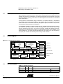
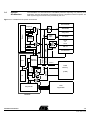
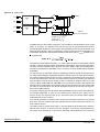
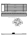
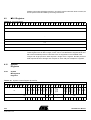
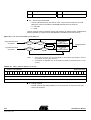
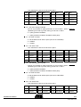
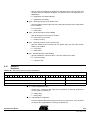
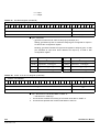
In software debug mode the timers are controlled by a system register bit (phlt – bit 4 in
Timer Control Register – TIMCTR) and an external pin (DEBUG). Setting the external
pin IWDE to VCC enables the Watchdog Timer. Otherwise the watchdog function must
be externally provided.
While the halt mode is active, the timers are temporary halted.
Figure 3-4 Timers Halt
31
15
0
SYSCTR – (System Control Register)
IWDE
reset
Watchdog
Timer
gpt int
RTC
rtc int
3.6.8.1
DEBUG
Watchdog Clock
clk
General
Purpose
Timer
Real
Time
Clock
Timer
General-purpose
Timer
clk
enable
clk
SYSCLK
31
clk
enable
7 6
UARTB Halt
UARTA Halt
Peripherals Halt
clk
5
4 3
0
TIMCTR
(Timer Control Register)
ph
lt
wd int
clk
enable
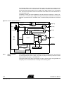
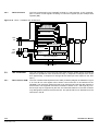
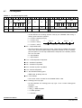
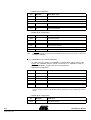
The General-purpose Timer (GPT) provides, in addition to a generalized counter function, a mechanism for setting the step size in which actual time counts are performed (a
two-stage counter). This timer/counter pulse generator consists of two parts:
pre-SCALER (GPTSR): it is a counter to adjust the step size in which counter does
the actual time count.
COUNTER (GPTCR): it is a counter to actually count time in steps as set by the value
in scaler. The counter is decremented when the scaler reaches zero.
Figure 1. GPT Implementation
Set
Preload
Cnt.
SYSCLK
Set
Preload
Cnt.
16-bit Scaler
zero
indication
GPT
Interrupt
32-bit Counter
Control
[enable, (periph_halt•DEBUG), load, re-load, hold, stop at zero]
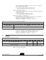
GPT is clocked by the internal system clock. The timer is programmable by writing to the
Timer Control Register (TIMCTR). They are possible to program to be either of singleshot type or periodical type and in both cases generate an interrupt when the delay time
TSC695F User Manual
3-27
4148H–AERO–12/03