1
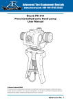
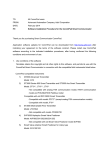
Yamatake Corporation
Introduction
1-3-2: Flange type detector
A Flange detector consists of the components shown in the figure below.
Grounding terminal
Waterproof gland
Terminal box cover
Terminal box
Flow direction mark
Flange
Grounding ring
Mounting screw
(4 places)
Electrode cover
Figure 1-5 Flange detector main parts
Name
Flow direction mark
Electrodes
Electrode cover
Grounding rings
Terminal box
(Remote model only)
Terminal box cover
(Remote model only)
Function
Indicates the direction of fluid flow. Mount the detector so
that the measured fluid flows in the direction indicated by
this mark.
Detect an electromagnetic force signal proportional to the
flow rate of the fluid passing through the detector. The
electrode material varies depending on the corrosion characteristics of the fluid to be measured.
Houses the electrodes. Do not remove the cover with the
detector installed on a pipe.
Keep reference voltage as zero by grounding the unit. The
grounding ring material varies depending on the corrosion
characteristics of the fluid to be measured.
Houses the connection terminals used for applying a standard voltage. Houses the excitation and signal terminals.
Keeps the terminals dry and protected. Keeps the terminal
box cover on during operation.
Model MGG18 - MagneW 3000 PLUS Smart Electromagnetic Flowmeter Detector
1-5