1
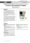
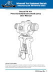
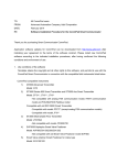
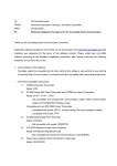
Installation Yamatake Corporation Dedicated cable structure The structure of the dedicated cable is shown in the following figure. The cable must be properly dressed to insure proper connection. Inside shield Conductive tube (black) Outside shield Inside sheath (black) Insulator (white) Outside sheath (black) Conductive wire (A) Conductive wire (B) Insulator (white) Inside sheath (white) Conductive tube (black) Inside shield Figure 2-45 Dedicated cable structure ~Note The conductive tubing (black) for conductive wires (A) and (B) is to be removed up to the end of the inside shield. Dressing the dedicated cable To dress the dedicated cable: (1) Scribe (cut) a line in the outside sheath (black) as shown in the following figure and remove the sheathing. The length varies depending on the model number of the cable. Make the length “L” slightly longer than necessary at first and then trim it to the specified length in Step 10. CAUTION Do not cut into the outside shield. Outside sheath (black) L mm (inch) Outside shield L mm (inch) Figure 2-46 Trimming the outside sheath ~Note If the terminal of the converter is designed not to use a shield drive, remove the outside shield and skip to Step 4. (2) Wind the lead wire once around the outside shield. (3) Solder the lead wire (C-wire) to the middle of the 5 mm (0.2 inch) length. Make the length of the lead wire slightly longer than necessary and trim it to the specified length in Step 10. 2-50 Model MGG18 - MagneW 3000 PLUS Smart Electromagnetic Flowmeter Detector