1
User Manual
ITC Technical Support:
1-800-631-5945 (Press 2)
1-732-548-5700 (Press 2)
ITC Customer Service:
1-800-631-5945 (U.S.) (Press 1)
1-732-548-5700 (outside U.S.)
This manual is published by International Technidyne Corporation (ITC) for use
with the IRMA TruPoint Blood Analysis System Version 7.1 or above.
Questions or comments regarding the contents of this manual can be directed to
the address at the bottom of this page or to your ITC representative.
IRMA® and IRMA TruPoint® are registered trademarks of ITC.
© Copyright 2008. This document is the copyright of ITC and must not be copied
or reproduced in any form without prior consent. ITC reserves the right to make
technical improvements to this equipment and documentation without prior
notice as part of a continuous program of product development.
441116
Rev.5
1010
This page intentionally blank
Table of Contents
Section
Page
1. The IRMA TruPoint® Blood Analysis System 1.1
Introduction
1.1
Intended Use
System Overview
CLIA Complexity Classification
Implementation
1.1
1.1
1.1
1.1
System Components
1.2
System - Major Components
IRMA TruPoint Blood Analyzer
IRMA TruPoint Battery Charger and Power Supply
IRMA TruPoint AC Power Adapter
IRMA TruPoint Cartridges
1.2
1.3
1.4
1.5
1.6
Getting Started
1.7
Unpack and Inspect the System
Bring the Analyzer to Room Temperature
Assemble the Charger
Charge the Battery
Unpack the IRMA TruPoint Cartridges
Cartridge Storage and Equilibration Procedure
Cartridge Temperature Operating Range
Insert Charged Battery or AC Adapter into Analyzer
1.7
1.7
1.7
1.7
1.8
1.8
1.9
1.9
System Features and Setup
1.9
Main Menu Access
Alternate Languages
IRMA TruPoint Touchscreen Interface
System Security
System Setup
System Features
Bar Code Reader
VueLink
Device Communication Utility (DeviceCom)
DeviceSet
1.9
1.10
1.10
1.11
1.12
1.12
1.15
1.18
1.20
1.20
i
Section
Page
2. Patient Sample Analysis
2.1
Overview
2.1
Sample Requirements
2.1
Acceptable Specimens
Syringe Requirements
Capillary Requirements
Sample Size
General Sample Collection Guidelines
Blood Gas Sample Handling
Electrolyte/Glucose/Lactate Sample Handling
Preparing the Sample for Injection
2.1
2.1
2.2
2.2
2.2
2.2
2.3
2.3
Sample Injection
2.4
Injecting a Syringe Sample
Injecting a Capillary Sample
2.4
2.6
Patient Test Procedure
2.6
Performing a Patient Test
2.6
Test Information Entry
2.13
Entering Test Information
Test Information Entry – Miscellaneous
2.13
2.16
Oxygen Therapy Information Entry
2.16
Entering Oxygen Therapy Information
Oxygen Therapy Entry – Miscellaneous
2.16
2.18
Patient Bypass Status
2.19
Selecting Patient Bypass Status
2.19
Patient Notes
2.19
Entering Patient Notes
2.19
QC Lockout
2.20
Satisfying QC Lockout - General Rules
QC Lockout Screens
2.20
2.20
References
2.21
ii
Section
Page
3. Quality Control Testing
Overview
3.1
3.1
IRMA TruPoint Quality Control
3.2
Quality Control Recommendation
3.3
Run an EQC Test:
Run Two Levels of Liquid Control:
Additional Liquid Control Testing:
Run a Temperature Test:
3.3
3.3
3.3
3.3
Electronic Quality Control
3.4
Performing a Manual EQC Test
Automatic EQC Test
3.4
3.6
Liquid Quality Control
3.6
Liquid QC Material Requirements
Performing a Liquid Control Test
Initiate Liquid QC Test
3.6
3.7
3.7
Temperature test
3.13
Performing a Temperature Test
3.13
References
3.14
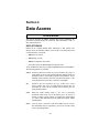
4. Data Access
4.1
Overview
4.1
Data Storage
4.1
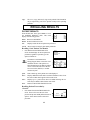
Recalling Results
4.2
Patient Results
Quality Control Results
4.2
4.5
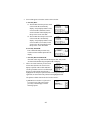
Results Transfer
4.9
Manual Transfer of IRMA TruPoint Results
Automatic Results Transfer
4.9
4.10
iii
Section
Page
5. Troubleshooting
5.1
Overview
5.1
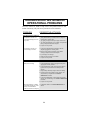
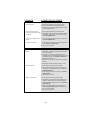
Troubleshooting General Operational Problems
5.2
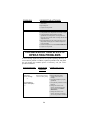
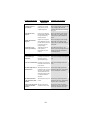
Troubleshooting Specific Operating Problems
5.4
6. Maintenance
6.1
Overview
6.1
Battery Maintenance
6.1
General Instructions
Removing the Battery
Charging the Battery (Routine)
Conditioning the Battery
6.1
6.3
6.3
6.4
Analyzer Maintenance
6.4
Changing the Printer Paper
Calibrating the Barometer
6.4
6.5
Cleaning System Components
6.5
Cleaning the Touchscreen
Cleaning the Battery Charger, Power Supply, and
Analyzer Surfaces
Cleaning the Battery Contacts
Cleaning the Infrared Probe
Cleaning the Edge Connector
Cleaning the Temperature Card
6.5
6.6
6.6
6.6
6.7
6.7
Replacing the Edge Connector
6.8
7. System Settings
7.1
Overview
7.1
Setting Options Menu
7.1
Test Settings
7.2
Product Setup
Lot Entry
Calculations
Test Information
7.2
7.3
7.4
7.6
iv
Section
Page
Correlation
Bypass Correlation
Display Units
Reference Ranges
Reportable Ranges
7.8
7.11
7.12
7.12
7.14
Quality Control (QC) Settings
7.15
QC Lockout
Controls
7.15
7.17
User ID Settings
7.19
Default QA User ID
Adding a New QA User ID
User ID Options
7.20
7.20
7.21
Device Settings
7.22
Beeper
Calibrate Barometer
Communications
Date Format
Date/Time
Auto Print
Screen Contrast
VueLink
7.22
7.22
7.23
7.27
7.27
7.28
7.28
7.28
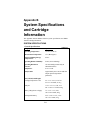
8. Appendixes
A: Limitations and Safety Precautions
A.1
B: System Specifications and Cartridge Information
B.1
C: Principles of Operation
C.1
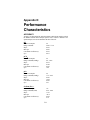
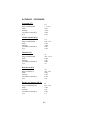
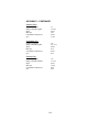
D: Performance Characteristics
D.1
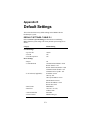
E: Default Settings
E.1
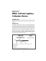
F: IRMA TruPoint Capillary Collection Device
F.1
G: Software Updates
G.1
H: Warranty
H.1
v
This page intentionally blank
vi
Section 1
The IRMA TruPoint®
Blood Analysis System
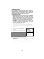
INTRODUCTION
This section outlines general information about the IRMA TruPoint Blood
Analysis System, and describes the installation process.
INTENDED USE
The IRMA TruPoint Blood Analysis System is intended for use with IRMA
TruPoint cartridges for the in vitro measurement of various critical care
analytes in human whole blood. See Appendix B, Table B-6 for a list of the
analytes that may be measured with the IRMA TruPoint system.
SYSTEM OVERVIEW
The major components of the IRMA TruPoint system are a portable, batteryoperated analyzer, and disposable cartridges that contain sensors and a
calibrant. Cartridges come in a variety of analyte configurations.
Cartridges calibrate with every test using the self-contained calibrant.
Instructions displayed on the interactive touchscreen guide the user through
all steps of the testing process. Patient and sample information can be entered
during analysis. Test results are displayed within approximately 90 seconds
after sample injection. Test results and associated information can be
automatically printed via the on-board printer. Test results and associated
information can be transmitted via serial, LAN10/100, or modem port to the
Integrated Data Management System (idms) or other connected system
capable of accepting ASTM output.
CLIA COMPLEXITY CLASSIFICATION
The IRMA TruPoint Blood Analysis System has a “moderate complexity”
CLIA classification. The optional SureStep®Pro Glucose Module has a
“waived status” CLIA classification (see SureStep®Pro Glucose Module User
Manual).
IMPLEMENTATION
An implementation protocol is available from your service provider upon
request.
1.1
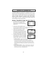
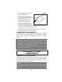
SYSTEM COMPONENTS
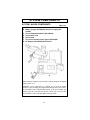
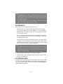
SYSTEM - MAJOR COMPONENTS
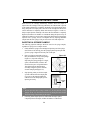
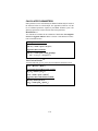
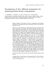
Figure 1-1
A. IRMA TruPoint analyzer
B. Battery charger (PN 442900) and power supply (PN
573400)
C. Two rechargeable batteries (PN 448700)
D. Temperature card
E. User manual
F. Two rolls of thermal printer paper (PN 403800)
G. AC Adapter (PN 440100)-Not Pictured
IRMA TruPoint cartridges (not pictured) are ordered, packaged, and shipped
under separate cover.
Additional system components are available for use with the IRMA
TruPoint system, including the Integrated Data Management System (idms),
the SureStepPro Glucose Module (PN 444100), an AC power adapter (PN
440100), and a bar code reader (PN 463120). Contact your service provider
for information on these and other IRMA TruPoint products.
1.2
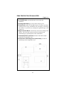
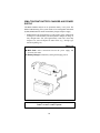
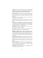
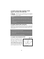
IRMA TRUPOINT BLOOD ANALYZER
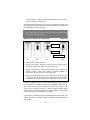
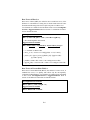
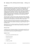
Figure 1-2
A. Carrying Handle
B. On-board Printer: provides hard copies of test results and
information.
C. Rechargeable Battery: provides portable analyzer power.
D. Touchscreen: guides user through all aspects of analyzer operation,
including analyzer setup, information entry and display, and testing.
The analyzer is powered-on by touching the right-hand edge of the
touchscreen.
E. Edge Connector Block: electronically connects the cartridge to the
analyzer. This removable connector protects the analyzer from
internal damage by spilled liquids or other contaminants.
F. Infrared (IR) Probe (recessed): measures and controls sample
temperature for appropriate tests.
G. Temperature Card Storage Area (underneath): provides onboard storage of the Temperature Card.
1.3
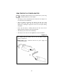
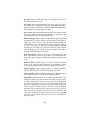
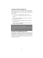
IRMA TRUPOINT BATTERY CHARGER AND POWER
SUPPLY
The IRMA TruPoint analyzer can be operated on battery or AC power. The
IRMA TruPoint battery power system consists of two rechargeable nickel metal
hydride (NiMH) batteries and an external battery charger and power supply.
• NiMH batteries take approximately 5.5 hours (battery empty when placed
in charger) to 10 hours (battery full when placed in charger) to charge. A
fully charged batter will yield approximately 30-40 tests when fully
charged. Test yield will depend on other factors (e.g., cartridge type,
amount of printing, etc.)
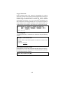
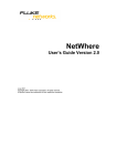
Figure 1-3
A. Power Supply and Attached Cord: connects to battery charger.
B. Wall Cord: makes connection between the power supply and
electrical wall outlet.
C. Battery Charger: holds battery during the charging process.
Caution: Battery charger with power supply is not intended for use
within a 1.5 meter radius of patient.
1.4
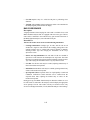
IRMA TRUPOINT AC POWER ADAPTER
The IRMA TruPoint analyzer can be operated on AC power using
the IRMA TruPoint AC power adapter.
• The analyzer will not automatically shut off when the AC adapter is in
use, and can be left on indefinitely.
• After two minutes of inactivity, the analyzer will enter into “sleep
mode” (screen goes dark). The user can return to the last screen
displayed by touching the right side of the screen at anytime during
sleep mode.
• If the user ID feature is enabled, then the user ID screen will be
displayed before the analyzer can be accessed again.
• The analyzer power can be left on indefinitely
• The analyzer can be shut off via the quit button on the main MENU.
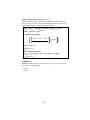
Figure 1-4
A. Power Supply and Battery Shell: are permanently connected via
the adapter cord. The battery shell fits into the IRMA TruPoint
battery compartment.
B. Wall Cord: makes connection between the power supply and
electrical wall outlet.
1.5
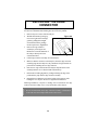
IRMA TRUPOINT CARTRIDGES
Each IRMA TruPoint cartridge contains a sensor array and self-contained
calibrant. One patient or liquid QC test is performed on each cartridge.
Figure 1-5
A. Cartridge Leads: electronically connect the cartridge to the analyzer.
B. Luer Injection Port: where the sample collection device attaches to
the cartridge.
C. Sensors: measure analyte concentrations.
D. Calibrant Gel: covers the sensors and is used to calibrate the sensors.
E. Temperature Monitoring Site (Internal): where IRMA TruPoint IR
probe measures and controls sample temperature.
F. Enzyme Pad: may be present on cartridges that employ enzymatic
methodologies.
G. Overflow Indicator: alerts user that the maximum sample volume
(5 mL) that the cartridge can hold has been reached.
H. Waste Reservoir: holds a maximum sample volume of 5 mL.
I. Air Vent: located on the bottom, left side of the waste reservoir.
J. Cal Cap: contains calibrant for cartridges with enzymatic sensors.
1.6
GETTING STARTED
UNPACK AND INSPECT THE SYSTEM
• Verify that all components have been received, and inspect components
for shipping damage. Immediately report any shipping damage to your
service provider.
• Retain one set of packaging materials. Analyzers requiring service by the
manufacturer must be returned in the original packaging materials. If the
original packaging materials are not available, contact your service
provider to order a replacement.
BRING THE ANALYZER TO ROOM TEMPERATURE
• The IRMA TruPoint temperature operating range is 12-30°C (54-86°F). If
the analyzer is exposed to a temperature outside of that range for a
significant period of time, an instrument temperature error message may
display. The analyzer must equilibrate at a temperature within the
temperature operating range for a minimum of 30 minutes before testing
may resume.
ASSEMBLE THE CHARGER
• Connect the power supply to the IRMA TruPoint charger.
• Connect the wall cord to the power supply.
• Plug the wall cord into an electrical wall outlet (110 VAC/60Hz or 220
VAC/50 Hz).
CHARGE THE BATTERY
Conditioning Charge:
Prior to initial use, condition each battery as follows:
• Insert a battery into the battery charger. The battery should ‘click’ into the
charger when properly inserted. The yellow light indicates that the battery
is charging. Charge the battery for 24 hours.
• After 24 hours, remove the battery from the charger, then reinsert the
battery into the charger. Leave the battery in the charger until the green
light flashes continuously, indicating that the battery is fully charged. The
battery should remain in the charger until it is needed for use in the
analyzer.
Routine Charge:
See Section 6-Charging the Battery - Routine for routine battery charging
instructions.
1.7
UNPACK THE IRMA TRUPOINT CARTRIDGES
IRMA TruPoint cartridges are shipped in an insulated shipping container. The
shipping temperature range is 0-50°C.
• Check the shipping temperature indicators that are enclosed with each
shipping container. Instructions accompany the indicators. If the
temperature indicators show that the shipping temperature range has been
exceeded, do not use the cartridges. Call your service provider for
replacement cartridges.
CARTRIDGE STORAGE AND EQUILIBRATION
PROCEDURE
Most cartridges are stored at room temperature. Some cartridges, however,
require refrigeration. Refer to Appendix B, Table B-7 for cartridge storage
temperature information for all cartridge types.
Room Temperature Cartridge Storage and Equilibration Procedure
• IRMA TruPoint cartridges that require storage at room temperature (1530°C/59-86°F), must be removed from their shipping container and
equilibrated to room temperature prior to use. Equilibration times depend
on the product type. Refer to Appendix B, Table B-7 for equilibration
times.
Equilibrate cartridges as follows:
• Remove cartridges from their shipping container upon receipt.
• Place cartridges in the area where they will be stored. The storage area
must have a stable temperature between 15-30°C (59-86°F). The cartridge
storage temperature must not fluctuate more than 8°C (14.4°F). If it does,
the cartridges must go through an additional equilibration period before
they can be used.
• Proper storage conditions should be documented daily by recording the
minimum and maximum storage area temperatures.
Refrigerated Cartridge Storage Procedure
• The CR cartridges are stable through the expiration date indicated on the
package label. CR Cartridges must be removed prior to use from the
refrigerator and sit at room temperature (15-30°C) for a minimum of 15
minutes.
• CR cartridges must be used within 8 hours of removal from the
refrigerator.
• CR Cartridges that are not used within 8 hours should be discarded. Do
not place unused cartridges back into the refrigerator.
1.8
CARTRIDGE TEMPERATURE OPERATING RANGE
The IRMA TruPoint temperature operating range is 12-30°C (54-86°F).
• Room temperature cartridges that are used in environments below the
cartridge storage temperature range (e.g., CVORs below 15°C/59°F) must
be used within 4 hours of transfer from the 15-30°C storage area to the
colder area. Cartridges that were not used within the 4 hour time limit
must be returned to the 15-30°C storage area, and go through an additional
equilibration period before they can be used. Refer to Appendix B, Table
B-7 for equilibration times.
• Refrigerated cartridges may be used until their out-of-refrigerator outdate.
INSERT CHARGED BATTERY OR AC ADAPTER
INTO IRMA TRUPOINT ANALYZER
• Insert a charged battery or AC Adapter into the IRMA TruPoint analyzer.
The insertion area is located on the left side, below the carrying handle.
SYSTEM FEATURES AND SETUP
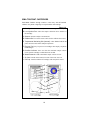
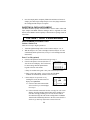
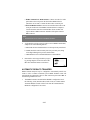
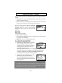
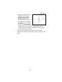
MAIN MENU ACCESS
All IRMA TruPoint test, setup, and recall options are accessed via the main
MENU. To access the main MENU:
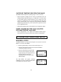
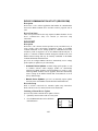
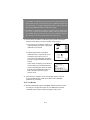
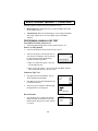
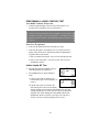
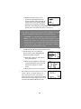
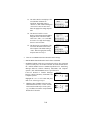
1.
Touch the right-hand edge of the screen to turn the analyzer “on.”
a. If the User ID option has not been activated, the main MENU
automatically appears at start-up.
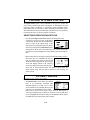
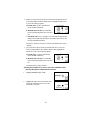
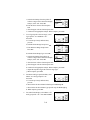
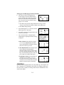
b. If the User ID option has been activated,
the Enter ID screen appears. This option
requires the entry of a valid User ID code
before the analyzer can be used.
Following entry of a User ID, the main
MENU displays.
The main MENU also appears following
completion of a test by pressing the done button
or the Menu button from other screens.
1.9
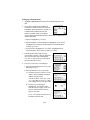
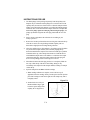
ALTERNATE LANGUAGES
The IRMA TruPoint analyzer software is available in multiple languages. All
available languages are automatically loaded into the analyzer during the
software installation process.
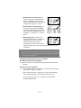
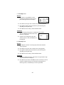
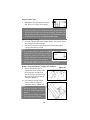
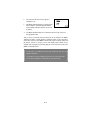
To select an alternate IRMA TruPoint analyzer software language:
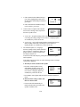
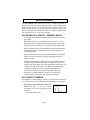
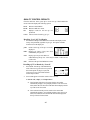
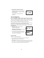
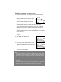
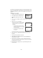
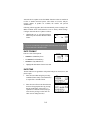
1.
Touch the right-hand edge of the screen to
start power-up. Press down and hold the ITC
logo that appears in the center of the screen
during power-up. Continue to press down
(logo will flash off) until the Select
Language screen appears.
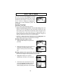
2.
The Select Language screen displays a
picklist containing all available analyzer
languages. Highlight the desired language
and press next. The main MENU displays in
the language selected.
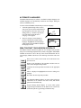
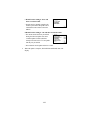
IRMA TRUPOINT TOUCHSCREEN INTERFACE
The IRMA TruPoint touchscreen guides the user through each procedure
using screens containing simple directions, buttons, and graphics. Most IRMA
TruPoint screens have a title at the top of the screen that describes the onscreen display. IRMA TruPoint uses the following conventions and screen
icons:
Does not save entries on the current screen and returns to the
previous screen.
Returns to the beginning of the procedure and does not save
entries made throughout the procedure.
Completes the current procedure and returns to the appropriate
menu.
Allows a displayed or highlighted screen item or setting to be
changed.
Proceeds to the next step in the procedure.
Test Information Button displays on screens where patient test
information can be added to test result record, and initiates
patient test information entry.
Oxygen Therapy Button displays on screens where patient
oxygen therapy information can be added to test result record,
and initiates patient oxygen therapy information entry.
1.10
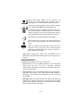
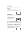
Bypass Status Button displays on the Calibrating and
Analyzing screens when available. When “On Bypass” option is
selected, Bypass Correlation hematocrit results are reported.
Temperature Test Button displays on the QC TEST OPTIONS
screen, and initiates an IRMA TruPoint temperature test.
QC Lockout Icon may be displayed on the Select Product Type
screen during a patient test. Product types that are locked out
will have the padlock icon over their selection button, and may
not be selected until QC lockout requirements have been met.
Pressing this key erases the last character in the display.
Patient Temperature Icon displays with patient temperature in
both °F and °C in upper-right corner of a blood gas test results
screen.
Battery Icon displays in the upper-right corner of all screens
except the patient test and QC test screens. A dark meter bar in
the battery icon represents the battery capacity. See Section 6Battery Maintenance for details.
• Alpha-numeric keyboard entry: Allows entry of information from an
alpha-numeric keypad that automatically appears when a keypad entry is
required.
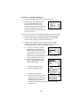
SYSTEM SECURITY
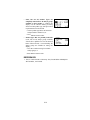
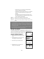
The IRMA TruPoint analyzer offers 3 user security levels:
• QA User(s) have access to all IRMA TruPoint test, recall, and setting
options. QA Users have sole access to barometer calibration,
communications configuration, results transfer, VueLink, and setup of QC
Lockout, User ID, and QC.
• General Users have access to all IRMA TruPoint test and recall options,
and limited setting options. These setting options include enabling or
disabling the beeper and printer, and setting the time, date format, and
screen contrast.
• Gluc Strip Users may perform and recall only glucose strip, EQC, and
temperature tests, and have limited access to setting options. These setting
options include enabling or disabling the beeper and printer, and setting
the time, date format, and screen contrast.
1.11
Note:
• The Gluc Strip User privilege is available for users that have purchased
the SureStep®Pro Glucose Module, an optional side attachment to the
IRMA TruPoint analyzer. Refer to the SureStep®Pro Glucose Module
User Manual for details.
• The General User privilege allows both IRMA TruPoint cartridge and
glucose strip testing (if glucose module is present).
SYSTEM SETUP
Prior to initial testing, complete the following activities:
• Identify QA User(s) to supervise IRMA TruPoint setup and monitoring.
• Use the factory default QA User ID “123456” to access the USER ID
SETTINGS menu. New QA User ID(s) may be added, and the default QA
User ID deleted if desired.
• Review the factory default analyzer settings in Appendix E, and make any
necessary adjustments. Refer to Section 7-System Settings for instructions
on changing default settings.
• Perform an EQC test (Section 3-Performing an EQC Test). When the test
is complete, access the barometer setting, and check the reading against
the barometer in your facility. If necessary, change the barometric pressure
value in the analyzer (Section 7-Calibrate Barometer).
Note:
• The IRMA TruPoint barometer was calibrated at the factory, and should
read within ± 5 mmHg of a NIST-calibrated barometer. Use of a nonNIST-calibrated barometer to adjust the IRMA TruPoint barometer
reading is not recommended.
• Enter appropriate User IDs if the User ID feature is enabled.
• Establish quality control procedures and set-up liquid controls (control
type, lot, level, and limits).
SYSTEM FEATURES
The IRMA TruPoint analyzer provides many optional software features that
can be activated from the main MENU via the Settings Option. The following
is a summary of these features. Please refer to Section 7-System Settings for
additional detailed information.
1.12
• Auto-Print: Enables automatic printing of results immediately upon
completion of analysis, or delayed auto-printing after sample and/or
oxygen therapy information entry is complete. If this feature is “off”, a
printout can still be obtained via the print key on the touchscreen.
• Bar Code Reader: A bar code reader is available for IRMA TruPoint
analyzers equipped with an accessory port on the back of the analyzer.
Please refer to Section 1-Bar Code Reader for additional bar code reader
information.
• Beeper: When enabled, an audible beep alerts the user that an action is
required or that a message is displayed.
• Correlation: Allows optional entry of slope and intercept values for each
analyte to correlate IRMA TruPoint analyzer results to a reference
method.
• Correlation for Cardiopulmonary Bypass (Pump) Hematocrits:
Allows optional entry of hematocrit slope and intercept values specifically
for samples from patients on cardiopulmonary bypass to correlate IRMA
TruPoint hematocrit results to a reference method.
• Date Format: Date may be displayed in the following formats:
MM/DD/YY; YY/MM/DD; or DD/MM/YY.
• Date and Time: Allows the definition of the correct date and time. The
default analyzer date and time is U.S. Central Standard Time.
• Electronic QC (EQC): Quality control is performed through a
comprehensive diagnostic check of the IRMA TruPoint edge connector,
internal electronics, and analyte circuitry. EQC minimizes the use of
reagents and disposable cartridges required for liquid QC testing. EQC can
be configured to run automatically when the analyzer is powered by the
AC adapter.
• Oxygen Therapy Information: Allows optional entry of patient oxygen
therapy information to be associated with a patient blood gas test record.
• Patient ID: Allows optional or required entry of a patient ID when
performing a patient test. ID lengths (number of characters) may also be
defined.
• Patient Hemoglobin: Allows optional entry of a hemoglobin value, or
use of the calculated tHb value derived from an IRMA TruPoint
hematocrit result for the associated patient, to be used in the BEb
calculation when running a blood gas test.
• Patient Notes: Allows optional entry of up to 3 pre-defined patient notes
to be associated with a patient test record.
1.13
• QC Notes: Allows optional entry of up to 3 pre-defined QC notes to be
associated with a QC test record.
• QC Limits: Allows optional definition of an upper and lower limit for
each control lot, level, and analyte. The limits are reported on the analyzer
printout with each associated test, available through result recall, and can
be transferred via the ASTM output to the idms.
• QC Lockout: Allows optional definition of requirements (number of tests
per level per shift) for both electronic and liquid QC that must be met
before the analyzer can be used for patient testing.
• Reference Ranges: Allows ability to define reference ranges and provide
an optional entry of an upper and lower reference limit for each analyte by
sample type, and a reference range title. When activated, patient test
results that fall outside of the defined limits will be flagged “H” (High) or
“L” (Low). The ranges are reported on the analyzer printout with each
associated test and sample type. Reference ranges are stored with the
results at the time the test is performed; therefore, changes can be made to
the limits without affecting previous results.
• Reportable Ranges: Allows optional entry of user-defined upper and
lower reportable range limits for each analyte. User-defined reportable
range limits must be within the default IRMA TruPoint reportable range
limits.
• Results Transfer: Enables transfer of new or previously-transferred
results via the serial port, LAN 10/100 port, or the internal or external
modem utilizing ASTM standard format and communication protocols.
• Sample Type/Site: Allows optional selection of a sample type and site
(from pre-defined list) to be associated with a patient test record.
• Screen Contrast: Allows touchscreen backlight to be adjusted to one of
nine settings for optimal viewing in all ambient light conditions.
• Sleep Mode: When the analyzer is “on” and has not been used for two
minutes, the analyzer goes into a 2 minute sleep mode (screen goes dark)
to conserve battery power. The user can return to the last screen displayed
by touching the right side of the screen at anytime during sleep mode.
When powered by battery, the analyzer powers down if the 2 minute sleep
mode period passes without any activity. When powered by AC adapter,
the analyzer will not shut down after 2 minutes of inactivity in sleep mode.
Entry of a User ID is required (if the User ID feature is enabled) to exit
sleep mode. During the two minute sleep mode, the beeper (if enabled)
will beep every 15 seconds, unless the screen is on the main MENU or
Enter ID screens.
1.14
• User ID: Requires entry of a valid User ID prior to performing select
functions.
• VueLink: Allows IRMA TruPoint patient test results to be transmitted to
the Philips/Agilent patient monitor for display.
BAR CODE READER
Description
A high performance linear imaging bar code reader is available for use with
IRMA TruPoint analyzers that are equipped with an accessory port. The bar
code reader is connected to the round accessory port located on the back of
the IRMA TruPoint analyzer, next to the RJ45 serial port.
Intended Use
The bar code reader can be used to scan the following information:
• Cartridge information: Cartridge type, lot code, and cal code are all
encoded in a single bar code found on the cartridge package label. The
cartridge package may be scanned with each test instead of manually
selecting Product Type and verifying the information on the Verify
Information screen.
• Glucose test strip information: Lot code and Ctl code are encoded in
separate bar codes found on the SureStepPro test strip bottle. The bottle
label may be scanned with each test instead of manually selecting Product
Type and verifying the information on the Verify Information screen.
• User IDs: User ID bar codes may be scanned, replacing manual entry of
IDs via the touchscreen keyboard.
• Patient IDs: Patient ID bar codes may be scanned, replacing manual entry
of IDs via the touchscreen keyboard.
• QC Expected Values: Expected values for Liquid Quality Control and
Calibration Verification Control materials can be scanned from the
expected values chart, replacing the manual entry of values via the
touchscreen keyboard.
During power-up, the IRMA TruPoint analyzer determines whether or not a
bar code reader is connected to the analyzer, and will display the appropriate
screen prompts. The bar code reader will only be activated on the entry
screens for cartridge information, User ID, Patient ID and QC control settings.
1.15
Bar Code Scan Symbologies
The bar code reader is factory programmed to read the following bar code
symbologies:
Code 11
Code 39
Code 128
Codabar
EAN/JAN
Interleaved 2 of 5
Matrix 2 of 5
MSI
Plessey
Telepen
UPC
Scanner Specifications
Refer to the User’s Guide that came with the bar code reader for detailed
specifications and regulatory compliance statements.
Note:
• The Welch Allyn bar code reader uses a non-laser, red LED light source.
Connecting the Bar Code Reader
1.
Ensure that the IRMA TruPoint analyzer is turned “off”.
2.
Connect the bar code reader cable to the round keyboard port on the back
of the analyzer.
3.
The reader will be ready for use when the analyzer is powered back “on”.
Caution:
• The IRMA TruPoint analyzer can only determine the presence or
absence of a bar code reader during analyzer power-up. Do not connect
or disconnect the reader when the analyzer is “on”. Doing so may
result in damage to the reader or analyzer, or the display of incorrect
screen prompts.
Disconnecting the Bar Code Reader
1.
Ensure that the IRMA TruPoint analyzer is turned “off”.
2.
Disconnect the bar code reader cable from the keyboard port on the back
of the analyzer.
Mounting the Bar Code Reader
The bar code reader may be attached to the IRMA TruPoint analyzer using
the mounting clip that came with the reader.
Figure 1-6
1. Attach the clip to the IRMA
TruPoint handle as shown.
(Figure 1-6).
1.16
Figure 1-7
2.
Connect the bar code reader to
the clip. (Figure 1-7)
Operating the Bar Code Reader-General
To scan a bar code, position the bar
code 3-6 inches (7-15 cm) from the
reader light source window. Press and
hold the button on the bottom of the
reader and align the red light line with
the bar code. The red light line will
turn off and the IRMA TruPoint
screen will advance when the scan is
complete. (Figure 1-8)
Figure 1-8
button
Operating the Bar Code Reader-Patient Sample Analysis and
QC Testing
If a bar code reader is connected to the IRMA TruPoint analyzer, the
appropriate screen prompts will display upon initiation of a patient test or
liquid QC test. The bar code scanner can be used to scan the following
items:
• User ID
• Patient ID
• Cartridge Information: Product Type, Lot Code, and Cal Code are
encoded in the single bar code found on each cartridge package label.
• Glucose Test Strip Information: Product Type, Strip Lot, and Ctl
Code are encoded in the two bar codes found on each test strip bottle label.
• QC and Calibration Controls: QC product, level, lot number,
expiration date, and expected values are encoded in the series of bar codes
located on the ITC expected values sheet. These sheets are located at
www.itcmed.com.
1.17
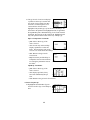
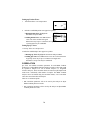
1.
Enter User ID (optional). If the User ID
option is activated, the Enter or Scan ID
screen will display. The User ID may be
entered using either the alpha/numeric
keypads or the bar code scanner.
a. Entry via touchscreen keypads - enter your User ID and press next.
b. Entry via bar code scanner - scan your User ID. The IRMA TruPoint
display will automatically advance to the next screen.
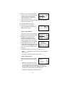
2.
Scan cartridge bar code. A screen instructing
you to Scan cartridge bar code will display at
the appropriate time. Scan the cartridge
package label for the cartridge to be used.
Note: To manually enter and/or verify
cartridge information, press manual entry.
a. Successful scan - cartridge product type, Lot Code, and Cal Code will
be accepted. The IRMA TruPoint display will automatically advance
to the next screen (the Select Product Type and Verify Information
screens will not be displayed).
b. Scanning Error - the Scanning Error
message will be displayed. The cartridge
bar code may be re-scanned, or the user
may press manual entry to manually enter
and/or verify product type, Lot Code, and
Cal Code.
VUELINK
Please contact your local representative regarding the current availability of
Vuelink.
Description
The Philips/Agilent VueLink module is a component for Philips/Agilent
patient monitors. VueLink allows IRMA TruPoint patient test results to be
transmitted to the Philips/Agilent patient monitor for display.
VueLink Setup
Refer to Section 7-VueLink for IRMA TruPoint VueLink setup instructions.
Patient ID should be configured “Required”.
Refer to the appropriate Philips/Agilent document for monitor operating
instructions and other information related to the Philips/Agilent patient
monitoring system and VueLink.
1.18
Transmitting Results to VueLink
1.
The patient test results displayed on the
Results screen are transmitted to VueLink
when done is pressed, only under the
following conditions:
• The VueLink option in DEVICE SETTINGS is “on”, and;
• The IRMA TruPoint analyzer is connected to a VueLink module
residing in a patient monitor or monitor rack. If there is no connection
between IRMA TruPoint and VueLink, pressing done will end the test
and advance IRMA TruPoint to the appropriate screen.
2.
The Sending to VueLink screen displays once
a connection has been established. The user
has 15 seconds to verify that the patient ID
from the test record transmitted matches the
patient ID entered into the patient monitor.
a. Patient ID verified within allotted time - test results display on the
patient monitor and the IRMA TruPoint advances to the appropriate
screen, depending on setup.
b. Patient ID not verified within allotted time - test results do not
display on the patient monitor and the IRMA TruPoint advances to the
appropriate screen, depending on setup.
Transmission Errors
If a connection is made, but the transmission is
unsuccessful, an error message will display.
a. Resend - verify connections and receiving
system and press resend button.
b. Cancel transmission - press cancel
button.
Transmitting Recalled Results
All IRMA TruPoint patient test results can be recalled and transmitted to
VueLink.
• A result can be transmitted multiple times.
• A result cannot be edited in IRMA TruPoint once it has been transmitted
to VueLink.
• Transmitting a result to VueLink does not affect its sent/unsent status for
transmission to idms or a host system.
1.19
DEVICE COMMUNICATION UTILITY (DEVICECOM)
Description
DeviceCom is a PC software application that handles all communications
between the IRMA TruPoint device and other software programs such as
idms.
DeviceCom Setup
There is no specific DeviceCom setup required in IRMA TruPoint. See the
Device Communication Utility User Manual for DeviceCom setup
instructions.
DEVICESET
Description
DeviceSet is a PC software tool that provides an easy and efficient way to
create, modify, restore and manage configuration settings on all IRMA
TruPoint instruments at a site. Settings profiles are established in DeviceSet
and then a profile is assigned to one or more IRMA TruPoint analyzers. A
profile is a collection of IRMA TruPoint settings that includes most of the
IRMA TruPoint settings that may be manually established via the IRMA
TruPoint SETTINGS OPTIONS menu.
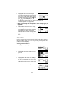
QA Users can configure IRMA TruPoint to automatically receive settings
profile updates, or updates may be sent manually.
• Automatic Device Updates: available settings profile updates, as well
as available software and/or language updates are automatically
transferred to IRMA TruPoint when downloading test results to idms.
Following IRMA TruPoint software upgrades, DeviceSet automatically
restores settings in the IRMA TruPoint that would otherwise revert to
factory default settings.
• Manual Device Updates: QA Users can manually request updates
from DeviceSet via the IRMA TruPoint SETTING OPTIONS menu.
DeviceSet Setup
Refer to Section 7-DeviceSet for automatic update setup instructions.
Refer to the DeviceSet User Manual for DeviceSet instructions.
Initiating a Manual Device Update
QA Users may initiate a manual device update as follows:
1.
Upload any unsent results to idms or a host system.
2.
Press the DeviceSet button on the SETTING
OPTIONS menu.
1.20
3.
a. If the Communications Method setting is
User Selects, highlight the button next to
the appropriate method and press next and
go to step 4.
b. If the Communications Method setting is
not User Selects, go to step 4.
4.
Connect cable to computer and verify that
DeviceCom is running. Select an option on
the Device Update screen:
a. “receive all” - All profile settings will be sent to the analyzer,
overwriting the existing settings. If new software or language updates
are available, they will be also be sent.
b. “receive new” - Only profile settings that have changed since the last
analyzer update will be sent to the analyzer. If new software or
language updates are available, they will be also be sent.
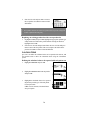
5.
The available updates (i.e., Languages,
Software, Settings, None), and the estimated
time it will take to complete the update will
display. If there is a profile associated with
the analyzer and there are
no unsent records in the analyzer, pressing ok will continue the update
until completion.
If the update cannot proceed for one of the following reasons, a message
screen will be displayed:
a. The analyzer is not associated with a profile.
> Press ok to continue update. Factory
default IRMA TruPoint settings will
overwrite existing analyzer settings. If
new software or language updates are
available, they will be also be sent.
> Press cancel to cancel update and return to the SETTING OPTIONS
menu.
b. Result Transfer setting is “idms” and
there are unsent results.
> Unsent results will automatically be
transferred when ok is pressed from the
Updates Available screen.
1.21
c. Result Transfer setting is “host” and
there are unsent results.
> Results must be manually transferred to
the host system before the update can be
initiated. Press ok to return to the main
MENU.
d. Result Transfer setting is “off” and there are unsent results.
> The unsent stored results may be deleted
during the software update. Press ok to
continue update if stored results have
already been retrieved or if it is acceptable
that they may be deleted.
> Press cancel to cancel update and retrieve results.
6.
When the update is complete, THE SETTING OPTIONS menu will
display.
1.22
Section 2
Patient Sample
Analysis
OVERVIEW
This section describes the procedure for performing a whole blood patient
sample analysis on the IRMA TruPoint analyzer, including sample requirements, sample collection, and sample handling guidelines.
SAMPLE REQUIREMENTS
ACCEPTABLE SPECIMENS
• Fresh arterial or venous whole blood collected in a 1, 2, or 3 mL lithium
heparin syringe. Balanced or low-volume heparin is recommended for
ionized calcium testing; sodium heparin may be used, but sodium values
may be elevated 1-2 mmol/L.
• Fresh capillary whole blood collected in the IRMA TruPoint Capillary
Collection Device, which contains balanced lithium heparin.
• Fresh venous whole blood collected in a lithium heparin collection tube.
Balanced or low-volume heparin is recommended for ionized calcium
testing; sodium heparin may be used, but sodium values may be elevated
1-2 mmol/L. The sample should be transferred to a non-heparinized 1, 2,
or 3 mL syringe for injection into a cartridge.
SYRINGE REQUIREMENTS
Most standard ABG syringes are compatible with IRMA TruPoint cartridges.
The following general types of syringes should not be used with IRMA
TruPoint cartridges:
• Frictionless or “pulsating” syringes. These syringes have plungers that will
continue to travel downward after the user has stopped injecting. This may
result in a sensor error.
• Syringes that contain a mixing ball or non-dissolving disk impregnated
with heparin. The ball or disk may become lodged in the tip of the syringe,
and the sample may hemolyze when it is forced through or around the
plug during injection.
• Syringes that have a non-standard Luer hub that does not fit the IRMA
TruPoint cartridge Luer injection port.
2.1
CAPILLARY REQUIREMENTS
Capillary samples must be collected in the IRMA TruPoint Capillary
Collection Device. See Appendix F for detailed Capillary Collection Device
instructions.
SAMPLE SIZE
The minimum whole blood sample volumes that must be injected into a
single-use cartridge for a patient sample analysis are:
• 200 uL if sample collected in a syringe
• 125 uL if sample collected in an IRMA TruPoint Capillary Collection
Device.
• Ensure that sufficient sample is collected to meet the minimum volumes
required for injection into the cartridge.
GENERAL SAMPLE COLLECTION GUIDELINES
• Time sample collection to minimize delays between collection and
analysis.
• Avoid drawing samples above an IV line to prevent dilution of the sample
with IV fluid.
• When drawing a sample from an indwelling line, back-flush and clear the
line of IV fluids prior to sampling to remove anticoagulants or medications
which might interfere with the test.
• Allow the blood collection site to dry after being cleansed with alcohol to
prevent hemolysis.
• Fill the collection device to the appropriate capacity. Incomplete filling
may cause high heparin to blood ratios which may lower ionized calcium
results and may affect other results.
• Thoroughly mix samples collected in syringes.
BLOOD GAS SAMPLE HANDLING
• Expel any air present in the syringe immediately after collection and
before the sample is mixed. If a portion of the sample must be separated
for other testing, do not expose sample to air.
• If a sample cannot be tested within 5 minutes of collection:
> Expel all air from the syringe.
> Cap or seal-off the end of the collection device.
> Store the blood gas sample in an ice slurry.
> Thoroughly mix the sample while the cartridge is calibrating.
2.2
• Capillary samples must be free-flowing from an “arterialized” site. Avoid
excessive squeezing of the puncture site to prevent erroneous results that
could result from dilution of analytes or hemolysis.
ELECTROLYTE/GLUCOSE/LACTATE SAMPLE
HANDLING
• If a blood sample cannot be tested within 20 minutes of collection, keep
the collection device capped to minimize pH changes that could affect the
ionized calcium concentration.
• Do not ice samples that are to be analyzed for potassium; iced samples
may hemolyze.
• Analyze samples that are to be tested for glucose immediately; glucose
will decrease 5-10 mg/dL/hour as a result of glycolysis.
• Samples for lactate should be analyzed immediately on drawing as lactate
increases by as much as 70% within 30 minutes at 25° C as a result of
glycolysis.1
PREPARING THE SAMPLE FOR INJECTION
• Remove any entrapped air from the syringe sample by pointing the syringe
at an upward angle to allow air bubbles to rise to the surface; expel the air,
along with a small amount of blood, onto an absorbent surface.
• Mix the sample thoroughly using the following technique:
> Roll the syringe between the palms of both hands with the syringe tip
pointing up.
> Invert the syringe (i.e., tip down) after 15-30 seconds. Continue to roll
the sample, alternating syringe orientation, until thoroughly mixed.
• Check the expelled sample for blood clots. A clot usually indicates
inadequate sample anticoagulation (e.g., the sample and heparin were not
well mixed). If a clot is injected near or over the cartridge sensors,
erroneous test results or sensor errors could occur. Do not use clotted
samples.
• When using the IRMA TruPoint Capillary Collection Device, analyze the
sample immediately, or place a luer cap on the tip of the device and
analyze within 5 minutes.
2.3
SAMPLE INJECTION
With each test, the cartridge automatically calibrates before the sample is
injected into the cartridge. Following calibration, the calibrant that is present
in the sample path must be completely displaced by the blood sample that is
being analyzed. The sample path is the area of the cartridge that houses the
sensors and must be completely filled with blood (see Figures 2-2 and 2-3).
Proper sample injection technique will ensure that the calibrant is completely
displaced, and that no air bubbles are introduced during the injection step. If
calibrant or bubbles are present in the sample path following the initial sample
injection from a syringe, the user can displace them by injecting additional
sample from the same syringe. This prevents sensor errors and sample loss.
INJECTING A SYRINGE SAMPLE
The following injection technique should be used for all syringe samples,
regardless of syringe size or sample volume:
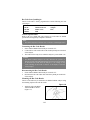
1. Firmly attach the syringe to the cartridge luer injection port. If the syringe
does not have a luer lock tip, place the syringe tip in the injection port and
give the syringe a slight twist to firmly seat it in the port.
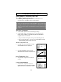
2.
Place your fingers around the syringe so
that your thumb rests on top of the plunger
(Figure 2-1). Inject the sample by
depressing the syringe plunger in a single,
quick, controlled motion, similar to the
motion used to press a stopwatch button.
This initial injection should be done
forcefully enough to eject the calibrant
from the sample path (Figure 2-2).
Figure 2-1
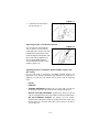
3.
Stop injecting when you feel the sample
eject the calibrant from the sample path.
If you can see the sample pushing the
calibrant out of the sample path, you are
injecting too slowly.
Figure 2-2
sample
path
Note:
• Do not inject the entire syringe contents (i.e., do not push the syringe
plunger all the way down until it bottoms out) during the initial sample
injection. Doing so may hemolyze the sample.
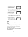
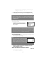
4.
Following initial sample injection, confirm that the sample path is
completely filled with sample, and that no bubbles or calibrant are
2.4
present (Figure 2-3). Bubbles or calibrant should rarely be seen if proper
injection technique is being used.
The sample path was designed to be easily viewed. If bubbles or calibrant are
present in the sample path, slowly inject additional sample to push them out of
the sample path and into the waste area.
Note:
• Do not pull sample from the waste area back into the sample path. Doing
so may cause inaccurate results.
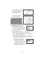
Figure 2-3
Bubbles or Calibrant in Sample Path
bubbles
calibrant
enzyme pad
A.
B.
C.
D.
A. Cartridge before sample injection.
B. Sample path properly filled after sample injection; sample path is
completely filled with no bubbles or calibrant present.
C. Sample path improperly filled after sample injection; sample path
contains bubbles (round) and calibrant (irregular). Bubbles or
calibrant may appear anywhere in the sample path.
D. Sample path (H4) properly filled after sample injection; sample path
is completely filled with no bubbles or calibrant present. Note that it
is normal for the enzyme pad to remain visible after sample injection.
If bubbles or calibrant do not move when additional sample is injected, tap the
top of the plunger to dislodge them, then inject additional sample from the
same syringe to push them into the waste area. The entire contents of the
syringe may be injected if necessary, to either reach the minimum sample
volume injection requirement (200uL) or to displace bubbles or calibrant. Do
not inject more than 5 mL of blood into the cartridge.
If air bubbles or calibrant gel cannot be displaced from the sample path, press
cancel to stop the test, discard the single-use cartridge, and begin again with a
new cartridge.
2.5
5.
Once the sample path is completely filled with a minimum of 200 uL of
sample, press test to begin sample analysis. Leave the syringe attached to
the cartridge until the analysis is complete.
INJECTING A CAPILLARY SAMPLE
The IRMA TruPoint Capillary Collection Device must be used to collect and
inject samples into IRMA TruPoint cartridges. Refer to Appendix F of this
manual, or the IRMA TruPoint Capillary Collection Device package insert for
instructions.
PATIENT TEST PROCEDURE
PERFORMING A PATIENT TEST
Initiate a Patient Test
There are two ways to begin a patient test:
1.
Touch the right-hand edge of the screen to turn the analyzer “on”; or
2.
With the analyzer “off”, insert a cartridge to turn the analyzer “on” and
automatically initiate a patient test (see steps 7-10 for cartridge insertion
instructions).
Enter User ID (optional)
3.
If the User ID option has not been activated, go to step 5.
4.
If the User ID option is activated, the Enter or
Scan ID screen will display. The User ID may
be entered using either the alpha/numeric
keypads or the bar code scanner.
a. Entry via touchscreen keypads - enter your User ID and press next.
b. Entry via bar code scanner - scan your User ID. The IRMA
TruPoint will automatically advance to the next screen.
5.
a. If the analyzer was powered “on” by
touching the screen, the main menu will
display. Press patient test.
a1. If no bar code reader connected the
Select Product Type screen displays.
Go to step 6
a2. If bar code reader connected - the Scan cartridge bar code screen
displays. Scan the cartridge package label for the cartridge to be
used. The cartridge product type, Lot Code, and Cal Code are
encoded in the single bar code on the cartridge label. The IRMA
TruPoint will automatically advance to the next screen (the Select
Product Type and Verify Information screens will not be
2.6
displayed). Go to step 7 if cartridge not yet inserted or step 13 if
cartridge has been inserted.
5.
b. If the analyzer was powered “on” by cartridge insertion, the Select
Product Type or Scan cartridge bar code screen appears following
insertion.
Note:
• If the QC Lockout option is “on”, and lockout requirements have not
been met, a lockout message will display. Refer to Section 2- QC
Lockout for details.
Select Product Type
6.
Highlight the desired product type and press
next. The Insert Cartridge screen displays. If a
cartridge was already inserted to initiate the
test, go to step 11.
Note:
• If only one product type was established in TEST SETTINGS/Product
Setup, the Product Type screen will not be displayed. The analyzer will
assume that the product is the same type as was established in TEST
SETTINGS/Product Setup. See Section 7-Product Setup.
Open Cartridge Package
7.
Check the expiration date on the cartridge package. The analyzer will not
allow testing with expired cartridges.
Note:
• If an expired cartridge is inserted into IRMA
TruPoint, the Lot expired message will display,
and the test cannot proceed. Remove expired
cartridge, and initiate a new test with an in-date
cartridge. If the wrong lot was selected on
the Verify Information screen, press ok to return to the Verify Information
screen and press edit to enter or select the correct cartridge lot.
8.
Remove the cartridge from the package and retain the package until
cartridge information is verified.
Remove Tape and Insert Cartridge into Analyzer
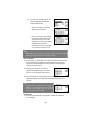
9.
Remove the protective tape from
the cartridge leads (if applicable).
2.7
Figure 2-4
Do not touch the cartridge leads
after the tape has been removed.
Do NOT remove the luer cap
from the cartridge. (Figure 2-4).
10. Fully insert the cartridge into the
analyzer within 15 minutes of
opening the package. (Figure 2-5)
Note:
• Do not use a cartridge if it has
been out of the package longer
than 15 minutes; do not reuse a
single-use cartridge once it has
been inserted into the analyzer.
Figure 2-5
Verify/Enter Cartridge Information
11. Ensure that the product type (Type)
displayed on the Verify Information screen
is correct. If the product type displayed does
not match the type of the cartridge inserted
into the analyzer, press back to return to the
Select Product Type screen.
12. The Verify Information screen displays the cartridge Lot and Cal Code
from the most recent test performed on the same product type.
a. If the Lot displayed matches the Lot of the cartridge inserted into the
analyzer, press next. Proceed to step 13.
b. If the Lot displayed does not match the Lot of the cartridge inserted
into the analyzer, press edit to choose a different previously-entered
Lot, or enter a new Lot for the first time.
b1. To choose a previously-entered Lot,
highlight the correct cartridge Lot
from the picklist. Press next to return
to the Verify Information screen. If the
information is correct, press next to
continue patient test. If the information is incorrect, press edit to
re-enter the Lot and Cal Code.
2.8
b2. To enter a new cartridge Lot for the
first time, highlight new from the
picklist and press edit.
› Enter the cartridge Lot using the
alpha keypad. Press next.
› Enter the Cal Code using the alpha
keypad. Press next to return to the
Verify Information screen. If the
information is correct, press next to
continue patient test. If the
information is incorrect, press edit
to re-enter the Lot and Cal Code.
Note:
• IRMA TruPoint generates an error if the calibration code is not verified
within approximately 2 minutes of cartridge insertion.
Select Analytes
13. If the QA User set up the analyzer to always automatically report results
for a specified group of analytes, the Select Analytes screen will not
appear; the analytes defined in the setup will always automatically be
reported. Proceed to step 16.
14. If the QA User set up the User Selects
option for the product being run, the Select
Analytes screen will appear with each test.
15. Select the analytes or analyte groups to be tested by highlighting the
appropriate button(s). Press next when all desired analytes have been
selected.
Note:
• Analytes that are locked-out will have a
padlock over the selection button, preventing
selection of that analyte until QC Lockout
requirements have been satisfied.
Calibration
16. Once the required data has been entered or verified, the calibration
process begins.
2.9
a.
For cartridges that have calibrant gel packaged over the sensors
(CC, BG, H3): calibration begins automatically. Proceed to step 17.
b.
For cartridges that have a Cal Cap (H4, GL, CR, LA): when the
Dispense Calibrant screen displays (with countdown timer at bottom),
follow the on-screen instructions for dispensing the calibrant over the
sensors. Depress the Cal Cap firmly and quickly to dispense the calibrant,
and press next. The calibrant must be dispensed within 1 minute or the
test is terminated and an Error message appears.
17. If the QA User enabled the test information,
oxygen therapy information, and/or bypass
status features, buttons will appear on the
Calibrating and Analyzing screens.
Information may be entered during calibration. Refer to Section 2- Test
Information Entry for instructions.
Remove Luer/Cal Cap, Inject Blood Sample, and Press “test”
18. The Calibration Complete screen displays
when calibration is complete. Twist and lift
the luer or Cal cap to remove it from the
injection port. The sample must be injected
within 4 minutes of completing calibration.
A timer displayed at the bottom of the screen counts down from 4
minutes. If more than 4 minutes elapse, the test is terminated and an Error
message appears.
Note:
• If an Error screen appears during calibration, refer to Section 5Troubleshooting for assistance.
19. Inject 0.125 mL (IRMA TruPoint Capillary Collection Device) or
0.2 - 5.0 mL (syringe) of blood into the cartridge within 4 minutes after
the cartridge is calibrated. Leave the collection device attached to the
cartridge. Refer to Section 2-Injecting a Syringe Sample or Section 2Injecting a Capillary Sample for sample injection details.
2.10
Note:
• If air bubbles or calibration gel are present in the sample path after the
initial sample injection, remove them by injecting additional sample from
the same syringe, or by lightly tapping the top of the syringe plunger and
then injecting additional sample from the same syringe.
• If air bubbles or calibration gel cannot be removed from the sample path,
press cancel to stop the test, discard the cartridge, and begin again with a
new cartridge. Proper injection technique will prevent air bubbles or calibration
gel from being present in the sample path after initial sample injection.
20. Ensure that no air bubbles or calibration gel are present in the sample
path, then immediately press test to continue sample analysis.
a. The Analyzing screen displays if there is no
required patient bypass status or patient ID
information to be entered.
b. If patient bypass status or patient ID
information entry is required, but not yet
entered, the Bypass Status screen or
Patient ID screen will display when test is
pressed. The required information must be
entered
before results will display or print. Refer to
Section 2-Entering Test Information and
Section 2-Patient Bypass Status for details.
Enter the required information and press
next to advance to the Analyzing (or
Results) screen.
21. When the test is complete, remove the cartridge with the collection
device attached. Dispose of both in accordance with established
guidelines for your facility.
View Test Results
22. Results automatically appear on the IRMA TruPoint touchscreen when
the analysis is complete. Press more to view additional measured or
calculated results if all the results do not appear on the screen.
2.11
a. Result outside of reference range: If
reference ranges were established by the
QA User, and a patient test result falls
outside of the defined limits, the result will
be flagged “H” (High) or “L” (Low).
b. Result outside of reportable range: If a
measured result is outside of the IRMA
TruPoint reportable range, that result, and
any corresponding calculated results, will
be flagged “<” (less than) or “>” (greater
than).
c. Result suppressed: If a sensor errors
during the analysis phase of a patient test,
the result for that sensor, any sensors
dependent on that sensor, and any
corresponding calculated values, will be
suppressed. Suppressed results will be dashed-out on both the screen
and printout.
Note:
• pH Normalized iCa results will be reported only for pH values within the
range of 7.2 - 7.6; if pH values fall outside of this range, pH Normalized
iCa results will be suppressed.
Complete Test Information Entry (optional);
Document Patient Notes (optional)
23. Refer to Section 2-Test Information Entry and Section 2-Patient Notes
for details.
Obtain a Printout (optional)
24. a. If the Auto-print setting is “immediate”, test results will automatically
print when the analysis is complete.
b. If the Auto-print setting is “delayed”, test results will automatically
print when the done button is pressed from the Results screen.
c. If the Auto-print setting is “off”, a printout may be obtained by
pressing the print button.
2.12
TEST INFORMATION ENTRY
The Test Information feature allows the user to enter information into the
IRMA TruPoint for each patient test. The entry options that are available for
selection with each test have been established by the QA User, and may
include any combination of the following: patient ID, patient temperature,
patient hemoglobin, sample type, sample site, MDRD GFR calculation and
FIO2. When entered, this information becomes a permanent part of the patient
test record, and may be transferred to the idms.
ENTERING TEST INFORMATION
• Press the Test Information button that
appears on the Calibrating, Analyzing,
Results, or Patient Recall/Last Results
screens. If this button is not present, the
QA User has not enabled this
feature or none of the options apply to the associated test record.
• The first test information entry screen will display. Enter information, or
press next to advance to the next entry screen.
Patient ID
Patient ID is the only test information item that may require entry. When
Patient ID was enabled by the QA User, two options were available for
selection:
• Optional Patient ID Entry: enter a one-to-twelve character ID to identify
the sample, or press next to leave the Patient ID blank.
• Required Patient ID Entry: enter a one-to-twelve character ID to
identify the sample. Results will not display or print until a Patient ID is
entered and next is pressed. This screen cannot be bypassed; the only way
to exit this screen is to enter a Patient ID.
• To automatically display the Patient ID from
the last patient test performed, press Prev. ID.
• If the ID entered or displayed exists in the
stored results, the remainder of the Test
Information fields are assigned the same values
as the most recent result for the same product type. If the previous values
are correct, press next to accept the values displayed, or change values as
necessary.
2.13
Note:
• If Patient ID entry is “Required”, and a patient ID was not entered during
the Calibrating phase, the Patient ID screen will display instead of the
Analyzing screen after sample injection. A patient ID must be entered
before results will display or print. Enter a patient ID and press next to
advance to the Analyzing (or Results) screen.
• If the analysis completes before the patient ID is entered, a flashing
“ANALYSIS COMPLETE” message displays in the upper right corner
of the Patient ID screen. Results will not display or print until a Patient ID
is entered and next is pressed. This screen cannot be bypassed; the only
way to exit this screen is to enter a Patient ID.
• If a Patient ID has not been entered (no results were displayed or printed),
and IRMA TruPoint powers-down, the test results may be viewed and
printed by recalling the result. If the test being recalled was the last
patient test performed on the analyzer, a patient ID can be entered upon
recall. Refer to Section 4-Recall Patient Results for instructions on
recalling last test result.
• If the test being recalled was not the last patient test performed on the
analyzer, the results can be viewed or printed, but a patient ID cannot be
entered. Refer to Section 4-Recall Patient Results for instructions on
recalling test results.
• A configuration option may have been selected by the QA User which
defines the minimum and maximum number of characters that must be
entered for a valid Patient ID. If the ID entered does not conform to the
defined ID length, an Invalid Length message will display. Enter a Patient
ID of acceptable length.
MDRD GFR
• If a CR test is being performed and the QA User has selected the GFR
calculation settings, the user can enter information to obtain the GFR or
they can skip the GFR.
• Enter the following information when the Gender screen appears:
> Select Male, Female or skip the GFR.
Press next.
> If a gender is selected then enter age in years.
Press next.
2.14
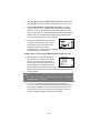
Patient Temperature
• The Patient Temperature option allows entry of
a patient temperature when performing a blood
gas test. A default temperature of 37°C automatically displays if a patient ID is not entered,
or no previous blood gas results exist for a patient ID. Press next to accept
the temperature displayed or enter a new temperature and press next.
Patient Hemoglobin
• The Patient Hemoglobin (manual entry) feature
allows entry of a hemoglobin value to be used
in the BEb calculation when running a blood
gas test. Press next to accept the hemoglobin
value displayed or enter a new value and press next.
Reference Range
• The Reference Range feature allows documentation of the reference range group selected.
Select the reference range group and press next.
Sample Type
• The Sample Type feature allows documentation
of the sample type collected. Press next to
accept the sample type displayed or enter a new
type and press next.
Sample Site
• The Sample Site feature allows documentation
of the sample site. Press next to accept the
sample site displayed, enter a new site, or select
other to enter a one-to-twelve character
free-text sample site. Press next.
• If the sample site selected is Brachial, Femoral, or Radial, highlight “right”
or “left” and press next.
FIO2
• If a blood gas test is being performed, and the
QA User has selected the Oxygen Therapy
setting FIO2 only, an FIO2 value may be
entered. Press next to accept the FIO2
displayed, or enter a new FIO2 value. Press next.
2.15
TEST INFORMATION ENTRY – MISCELLANEOUS
If test information entry is completed before calibration is complete, the
operator is automatically returned to the Calibrating screen.
If calibration completes at any time during test
information entry, the CALIB. COMPLETE
message appears in the upper right corner of the
test information screen. Complete information
entry, or press next through each remaining screen
to save entries and return to the Calibration Complete, Inject Sample screen.
None of the information screen entries will be saved until next is pressed on
the last entry screen. Pressing back to return to the Calibration, Calibration
Complete, or Analyzing screens will not save test information entries. Test
information entry can be resumed and completed during the Analyzing phase,
after the test is complete (Results screen), or upon recalling the last patient test
result.
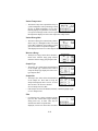
OXYGEN THERAPY
INFORMATION ENTRY
The Oxygen Therapy feature allows the user to enter oxygen therapy
information into the IRMA TruPoint for each patient blood gas test.
Information available for entry includes mode of oxygen therapy and the
relevant settings for each mode. When entered, this information becomes a
permanent part of the patient test record, and may be transferred to idms.
ENTERING OXYGEN THERAPY INFORMATION
• Press the Oxygen Therapy button that appears on the Calibrating or
Analyzing screens. If this button is not present,
the QA User has not enabled this feature or
none of the options apply to the associated test
record. Oxygen Therapy information can also
be entered by pressing the Test Information
button that appears on the Results screen following a test or upon recalling
the last patient test result.
• The first oxygen therapy entry screen will display. Enter information, or
press next to advance to the next entry screen.
2.16
Patient Status
• Highlight the appropriate Patient Status setting.
› If Code or Room Air status is selected,
press next to accept the selected oxygen
status and complete entry.
› If Pump status is selected, press next to access the FIO2 screen. Enter
FIO2 value and press next to access Comments screen. Enter a one- to
twelve-character comment (optional) and press next to complete entry.
› If the Oxygen status is selected, press next to access the Oxygen
Therapy screen.
Oxygen Therapy
• Highlight the appropriate Oxygen Therapy
mode. Press next.
• The entry options displayed depend on the
relevant settings for the selected oxygen
therapy mode.
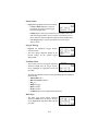
Ventilator Mode
• The Ventilator Mode screen appears following
selection of Vent. from the Oxygen Therapy
screen. Highlight the appropriate mode and
press next.
• The following information may be entered, depending upon the ventilation
mode selected:
› Tidal Volume (mL)
› Rate or Frequency (B/min.)
› FIO2 (%)
› PEEP (cm H2O)
› IPAP (cm H2O)
› EPAP (cm H2O)
› Comments (up to twelve alpha-numeric characters)
Mask Type
• The Mask Type screen appears following
selection of Mask from the Oxygen Therapy
screen. Highlight the appropriate mask type and
press next.
2.17
• The following information may be entered:
› If Venturi, Trach Collar, or High Flow is selected, enter the
FIO2 (%) and press next.
› If Simple or NRB is selected, enter the oxygen flow (L/min.) and press
next.
› If Other is selected, enter mask type (up to twelve characters); enter
the oxygen flow (L/min.) and press next.
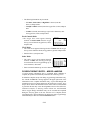
Nasal Cannula Mode
• The Oxygen Flow screen appears following
selection of Nasal Cannula from the Oxygen
Therapy screen. Enter the oxygen flow (L/min.)
and press next.
CPAP Mode
• The CPAP screen appears following selection of CPAP from the Oxygen
Therapy screen. Enter the CPAP (cm H2O) delivery pressure and press next.
• Enter the FIO2 (%) and press next.
Other Mode
• The “Other” Oxygen screen appears following
selection of Other from the Oxygen Therapy
screen. Enter the form of oxygen therapy (up to
twelve characters). Press next.
• Enter associated comments (up to twelve characters). Press next.
OXYGEN THERAPY ENTRY – MISCELLANEOUS
If oxygen therapy information entry is completed before calibration is
complete, the operator is automatically returned to the Calibrating screen.
If calibration completes at any time during oxygen therapy information entry,
the “CALIB. COMPLETE” message appears in the upper right corner of the
information screen. Complete information entry, or press next through each
remaining screen to save entries and return to the Calibration Complete, Inject
Sample screen. None of the information screen entries will be saved until next
is pressed on the last entry screen. Pressing back to return to the Calibration,
Calibration Complete, or Analyzing screens will not save test information
entries. Oxygen therapy information entry can be resumed and completed
during the Analyzing phase of the test. After the test is complete (Results
screen displayed) or upon recalling the last patient test result, oxygen therapy
information may be entered via the Test Information button.
2.18
PATIENT BYPASS STATUS
The Bypass Status feature, when established by the QA User, requires the
user to select a patient bypass status (“On Bypass” or “Off Bypass”) for each
patient test. When “On Bypass” is selected, the bypass correlation factors
established by the QA User will be used to determine the hematocrit results.
This information becomes a permanent part of the patient test record, and may
be transferred to idms. See Section 7-Bypass Correlation.
SELECTING PATIENT BYPASS STATUS
• Press the patient Bypass Status button (heart icon) that appears on the
Calibrating or Analyzing screens. If this button
is not present, the QA User has not enabled this
feature or none of the options apply to the
associated test record. Bypass status can also be
selected by pressing the Test Information button
that appears on the Results screen following a test or upon recalling the
last patient test result. Highlight the correct patient bypass status and press
next.
• Bypass status must be selected for each test that includes hematocrit when
this feature has been established by the QA
User. If a patient bypass status was not selected
during the Calibrating phase, the Bypass Status
screen will display instead of the Analyzing
screen after sample injection. A patient bypass
status must be selected before results will display or print. Select the
patient bypass status and press next to advance to the Analyzing (or
Results) screen.
PATIENT NOTES
ENTERING PATIENT NOTES
• The Patient Notes feature allows pre-defined
notes to be permanently associated with
individual patient test records. Up to 3 notes
can be attached to an individual patient record.
If the QA User enabled Patient Notes, a notes
button will be present on the Results screen. Press the notes button to
access the pre-defined notes available for selection. Use the up and down
arrows to highlight the desired note and press the check box button. Repeat
for additional notes, and press next when complete.
2.19
QC LOCKOUT
The QC Lockout feature allows the QA User to define the number of
successful QC tests (EQC and/or liquid) required to support patient testing.
When activated, either 1, 2, or 3 successful quality control tests must be run
during a shift or the analyzer will deny access to the patient test screen, or in
the case of a partial lockout condition, limit access to the tests available. Shifts
can be specified as 8-, 12-, or 24- hours in length.
SATISFYING QC LOCKOUT - GENERAL RULES
• QC Lockout can be configured separately for EQC, and for each product
type (liquid).
• When EQC Lockout is on, an EQC test failure at any time (i.e., even if
EQC passed earlier on a shift) will lockout patient testing. Following an
EQC test failure, a passed EQC test is required to resume patient testing.
• When liquid QC limits have been established, results must fall within the
established QC limits to be considered a successful test and satisfy QC
lockout requirements.
• When no liquid QC limits have been established, running the designated
number of controls will satisfy QC lockout requirements for all nonsuppressed results.
• Result Suppression during an liquid QC test: If an individual sensor on a
cartridge errors during the analysis phase of an liquid QC test, the result
for that sensor and any other sensors that are dependent on that sensor will
be suppressed. Suppressed results will be dashed-out on both the screen
and printout, and will not satisfy QC lockout requirements for the
associated analyte group (with or without QC limits established).
• If a patient test is initiated and QC Lockout is “on” and Lockout
requirements have not been met, a QC lockout screen displays.
QC LOCKOUT SCREENS
If a patient test is initiated and QC Lockout is on and Lockout requirements
have not been met, one of the following lockout information screen displays:
• All Analyte Groups and Product Types are
locked out (none of the QC lockout
requirements for the current shift have been
satisfied).
› Press ok to return to main.
2.20
• Some, but not all, Product Types are
completely locked-out for all analyte groups
available on that product. A padlock will
display over the selection button, preventing
selection of that product type until QC lockout
requirements have been satisfied.
› Select a product type that is not locked out
and press next to continue test; or
› Press cancel to return to main.
• Product types that are partially locked-out
(some, but not all, analyte groups available)
will not show a padlock icon over the selection
button. When selected, a screen detailing the
analyte groups not available for testing will
display.
› Press ok to continue testing for available
analyte groups; or
› Press cancel to return to main.
REFERENCES
1. Tietz, N. Clinical Guide to Laboratory Tests, Fourth Edition. Philadelphia:
W.B. Saunders, 1995: 4th Ed.
2.21
This page intentionally blank
2.22
Section 3
Quality Control Testing
OVERVIEW
Quality Assurance (QA) can be defined as the required systems and actions to
provide adequate confidence that a service, such as a point of care diagnostics
program, satisfies the medical needs of the patient.1 Quality Control (QC) is a
major component of a QA program, and can be defined as the systematic
process of assessing and documenting the analytical performance of an
analysis system.
By design, a point of care (POC) system is intended to be used by nonlaboratory clinical staff who typically do not have a background in the quality
control, analyzer maintenance, and calibration procedures that are inherent
components of traditional laboratory analyzer QA programs. Traditional
laboratory analyzer QC programs are designed to detect system problems
primarily through the use of liquid controls. System problems are typically
related to calibration or maintenance problems that result from the exposure
of the system and sensors to multiple samples. The IRMA TruPoint system
was designed to eliminate problems related to calibration and maintenance.
Single-Use Cartridges
The IRMA TruPoint system utilizes single-use cartridges, also referred to as
unit-use or disposable cartridges. Each cartridge houses miniaturized
electrochemical sensors and a pre-packaged calibrant. A single-use cartridge
is used to perform analysis on one sample, then is discarded.
Cartridge Calibration
Prior to sample introduction, the sensors on each IRMA TruPoint cartridge
are automatically calibrated using a pre-packaged calibrant. The calibrant is
manufactured and tested with NIST traceable gases and standards. Calibration
of the cartridge is completed when information determined at the factory for
each lot of cartridges (the Cal Code) is combined with measurements taken
during the calibration process. The factory derived Cal Code information is
stored in the analyzer memory following initial entry of a new cartridge lot, or
can be entered via the bar code reader.
3.1
IRMA TRUPOINT QUALITY CONTROL
The IRMA TruPoint Quality Control program consists of the following four
elements:
1.
Comprehensive, automatic, on-line quality and procedural checks
that continuously monitor sensor response and instrument response. The
IRMA TruPoint software monitors responses throughout both the
calibration and sample analysis phases of a test. If an uncharacteristic
response is detected during the calibration phase, the system rejects the
cartridge and does not allow that cartridge to be used for sample analysis.
Since sample introduction occurs after calibration, rejected cartridges do
not result in the loss of the sample. If an uncharacteristic sensor response
is detected during the sample analysis phase, the system suppresses that
sensor and does not report an analyte result for that sensor.
2.
Electronic Quality Control (EQC) is performed through a
comprehensive diagnostic check of the edge connector, internal
electronics, and analyte circuitry. An EQC test simulates the electronic
signals that are produced by IRMA TruPoint sensors during a cartridge
test. During an EQC test, an isolated region of the internal circuit board
sends a range of simulated sensor signals through the cartridge
measurement channels. The range of signals generated encompasses the
entire linear range expected from blood analysis. This measurement is
followed sequentially by measurements of conductivity out to the
connector pins, insuring that no contamination is present in the edge
connector which would interfere with test results. Signal measurements
must fall within strict predetermined thresholds for the test to pass.
IRMA TruPoint EQC is an internal method, and does not require the use
of an external EQC card. Analyzers powered by AC adapter can be
configured to automatically run EQC tests per a preconfigured schedule.
3.
Liquid Quality Control (LQC) is performed to verify proper shipping
and cartridge storage conditions using various liquid control solutions of
known analyte concentration. Control materials are commercially
available in levels corresponding to normal and abnormal clinical
conditions.
4.
Temperature Test is performed using the IRMA TruPoint Temperature
Card to verify proper operation of the IRMA TruPoint temperature
control system. Although the temperature is monitored continuously
during patient testing, the Temperature Card allow for easy external
verification.
3.2
QUALITY CONTROL
RECOMMENDATION
Following method verification and establishment of liquid quality control
limits, ITC recommends EQC as the primary method of assessing system
accuracy and precision. Since each test site may have unique requirements,
each site should select and verify a quality control system that meets their
needs. ITC recommends that QC be performed as follows:
RUN AN EQC TEST:
• Once per shift of patient testing on each analyzer;
• When the analyzer experiences a significant change in storage
temperature, (e.g., movement from a cold to a hot environment);
• Whenever the performance of the analyzer requires verification, according
to facility or regulatory agency protocol.
RUN TWO LEVELS OF LIQUID CONTROL:
• Before a new cartridge lot or shipment is put into use, (following the
required equilibration period) to verify proper shipping and equilibration
conditions. Cartridge lot verification is not required for each analyzer in
use.
ADDITIONAL LIQUID CONTROL TESTING:
• Is required only if cartridges are required to go through an additional
equilibration period due to temperature fluctuations of greater than 8°C
(14.4°F) in the cartridge storage area. Refer to Section 1-Cartridge
Equilibration Procedure for additional equilibration information.
• If cartridges are required to go through an additional equilibration period,
run two levels of liquid control before putting the cartridge lot back into
use.
RUN A TEMPERATURE TEST:
• Monthly to verify that the IRMA TruPoint temperature control system is
operating properly.
3.3
ELECTRONIC QUALITY CONTROL
Electronic Quality Control tests may be performed two ways:
1.
Manual EQC Test: initiated by user by pressing the EQC button on the
QC Test Options screen.
2.
Automatic EQC Test: runs automatically per a pre-configured schedule.
This feature requires the use of an AC adapter to power the IRMA
TruPoint.
PERFORMING A MANUAL EQC TEST
Turn IRMA TruPoint Analyzer On
1.
Touch the right-hand edge of the screen to turn the analyzer “on”.
Enter User ID (optional)
2.
If the User ID option has not been activated, go to step 4.
3.
If the User ID option is activated, the Enter or
Scan ID screen will display. The User ID may
be entered using either the alpha/numeric
keypads or the bar code scanner.
a. Entry via touchscreen keypads - enter your
User ID and press next.
b. Entry via bar code scanner - scan your User ID. The IRMA TruPoint
will automatically advance to the next screen.
Initiate an EQC Test
4.
Press QC Test on the main MENU. The QC
TEST OPTIONS menu displays.
5.
Press EQC on the QC TEST OPTIONS menu
to initiate the EQC test.
6.
The Analyzing screen appears, indicating that
the diagnostic tests are in progress.
Review Results
7.
Once the EQC test is complete, the analyzer
displays the EQC Results status screen. The
initial result for an EQC test is either “Passed”
or “Failed”.
3.4
a. Passed EQC Test:
Manual
a1. Press view to view quantitative results
(optional). Press next from each screen to
proceed through results for all analytes.
a2. Press notes to select QC notes to attach to the QC record (optional).
a3. Press print to obtain a printout. (Results may automatically print,
depending on auto-print setup).
a4. Press done to return to the QC TEST OPTIONS menu.
Automatic
a5. Results will print (if the printer is configured to print) and the
analyzer will display the main menu or user
ID screen (if required).
a6. If printer is not configured to print, there
will be no print out. The main MENU will
be displayed.
b. Failed EQC Test:
Manual
b1. Press help for assistance in resolving the problem that caused the
failure (optional).
b2. Press notes to select QC notes to attach to the record (optional).
b3. Press print to obtain a printout. (Results may automatically print,
depending on auto-print setup).
b4. Press done to return to the QC TEST OPTIONS menu.
Automatic
b5. If printer is configured to print, “EQC failed” will print and the “EQC
Results failed” screen will display.
b6. Press done to return to the main MENU or the User ID entry screen (if
required). Another auto-EQC test will initiate following the next
inactivity period, or a manual EQC test can be performed.
3.5
Note:
• When EQC Lockout is on, an EQC test failure at any time (i.e., even if
EQC passed earlier on a shift) will lockout patient testing. Following an
EQC test failure, a passed EQC test is required to resume patient testing.
AUTOMATIC EQC TEST
Refer to Section 7- QC Lockout for configuration instructions.
LIQUID QUALITY CONTROL
This section of the manual describes the liquid quality control test
procedure following set up of the control parameters (control type, lot
number, level, and limits) by the QA User. If controls have not been
established, the Unable to run QC Test, No Controls Defined message will
appear when an liquid QC test is attempted.
Before the test is started, review the control sample preparation recommendations described in steps 15-17 on page 3.10.
LIQUID QC MATERIAL REQUIREMENTS
• The IRMA TruPoint system requires liquid controls to verify cartridge
shipping and equilibration conditions. Control, linearity, and proficiency
testing material recommendations and ranges are available on the ITC
website (www.itcmed.com) or from your service provider or ITC
Technical Services.
• IRMA TruPoint BG, CC and LA cartridges require liquid blood gas
control, linearity, and proficiency testing material. Do not use
perfluorocarbon- based materials.
• The IRMA TruPoint cartridges require controls that contain physiologic
concentrations of electrolytes (i.e., controls that have assayed values for
electrolytes on the control package insert), even if electrolyte results will
not be reported.
• The IRMA TruPoint system requires hematocrit controls that are intended
for use with conductive hematocrit methodologies.
3.6
PERFORMING A LIQUID CONTROL TEST
Turn IRMA TruPoint Analyzer On
1.
Touch the right-hand edge of the screen to turn the analyzer “on”.
Do NOT insert a cartridge to power-on the analyzer.
Note:
• All QC tests must be initiated via the main MENU, QC Test option. If a
cartridge is inserted to power-on the analyzer, or inserted at the main
MENU screen, the analyzer will automatically initiate a patient test, not
a QC test.
Enter User ID (optional)
2.
If the User ID option has not been activated, go to step 4.
3.
If the User ID option is activated, the Enter or Scan ID screen will
display. The User ID may be entered using either the alpha/numeric
keypads or the bar code scanner.
a. Entry via touchscreen keypads - enter your User ID and press next.
b. Entry via bar code scanner - scan your User ID. The screen will
automatically advance.
Initiate Liquid QC Test
4.
Press QC Test on the main MENU. The QC
TEST OPTIONS menu is displayed.
5.
Press Liquid on the QC TEST OPTIONS
menu.
a. If no bar code reader is connected - the
Select Product Type screen will display. Go
to step 6.
b. If the bar code reader is connected - the
Scan cartridge bar code screen will display.
Scan the cartridge package label for the cartridge to be used. The
cartridge product type, Lot Code, and Cal Code are encoded in the
single bar code on the cartridge label. The IRMA TruPoint will
automatically advance to the Insert Cartridge screen (the Select
Product Type screen will not be displayed). Go to step 7.
3.7
Select Product Type
6.
Highlight the desired product type and press
next. The Insert Cartridge screen displays.
Note:
• If only one product type was established in TEST SETTINGS/Product
Setup, the Select Product Type screen will not display. The analyzer will
assume that the product is the same type as was established in TEST
SETTINGS/Product Setup. See Section 7-Product Setup.
Open Cartridge Package
7.
Check the expiration date on the cartridge package. The analyzer will not
allow testing with expired cartridges.
8. Remove the cartridge from the package and retain the package until
cartridge information is verified.
Note:
• If an expired cartridge is inserted into IRMA
TruPoint, the Lot expired message will display,
and the test cannot proceed. Remove expired
cartridge, and initiate a new test with an in-date
cartridge. If the wrong lot was selected on
the Verify Information screen, press ok to return to the Verify Information
screen and press edit to enter or select the correct cartridge lot.
Remove Tape and Insert Cartridge into Analyzer
9.
Remove the protective tape (if
applicable) from the cartridge leads.
Do not touch the cartridge leads
after the tape has been removed. Do
NOT remove the luer cap from the
cartridge. (Figure 3-1).
10. Fully insert the cartridge into the
analyzer within 15 minutes of
opening the package. (Figure 3-2)
Note:
• Do not use a cartridge if it has been
out of the package longer than 15
minutes.
• Do not reuse a cartridge once it has
been inserted into the analyzer.
3.8
Figure 3-1
Figure 3-2
Verify/Enter Cartridge Information
11. a. If the cartridge package bar code was scanned, go to step 13.
b. If manual entry, ensure that the product
type (Type) displayed on the Verify
Information screen is correct. If the
product type displayed does not match the
type of the cartridge inserted into the
analyzer, press back to return to the Select
Product Type screen.
12. The Verify Information screen displays the cartridge lot number (Lot) and
Cal Code from the most recent test performed on the same product type.
a. If the lot number displayed matches the lot number of the cartridge
inserted into the analyzer, press next. Proceed to step 13.
b. If the lot number displayed does not match the lot number of the
cartridge inserted into the analyzer, press edit to choose a different
previously-entered lot, or enter a new lot for the first time.
b1. To choose a previously-entered lot,
highlight the correct cartridge lot
from the picklist. Press next to return
to the Verify Information screen. If the
information is correct, press next to
continue QC test. If the information is incorrect, press edit to reenter the lot number and Cal Code.
b2. To enter a new cartridge lot for the
first time, highlight new from the
picklist and press edit.
› Enter the cartridge lot number
from the keypad. Press next.
› Enter the Cal Code from the
keypad. Press next to return to the
Verify Information screen. If the
information is correct, press next to
continue liquid QC test. If the
information is incorrect, press edit to re-enter the lot number
and Cal Code.
3.9
Dispense Calibrant (Cartridges with Cal Cap Only)
13. For cartridges that have a Cal Cap (H4, GL, CR, LA) the Dispense
Calibrant screen displays (with countdown timer at bottom). Follow the
on-screen instructions for dispensing the calibrant over the sensors.
Depress the Cal Cap firmly and quickly to dispense the calibrant, and
press next. The calibrant must be dispensed within 1 minute or the test is
terminated and an Error message appears.
Select Control Type, Lot, and Level to be Tested
14. Scroll through the list of established controls
using the arrow keys until the desired control
for the test is highlighted. Press next to select
the highlighted control. The Calibrating
screen appears, indicating that calibration is
in progress.
Note:
• IRMA TruPoint generates an error if the calibration code is not verified
or the control is not selected within approximately 2 minutes of
cartridge insertion.
Prepare Control Sample
15. Shake the control sample to equilibrate the gas and liquid contents
according to the manufacturer’s recommendations. To ensure sample
integrity, avoid warming the ampule in the palms of your hands, and do
not open the ampule until calibration is complete.
Remove Luer/Cal Cap, Inject Control
Sample, and press “test”
16. The Calibration Complete screen displays
when calibration is complete. Twist and lift
the luer or Cal cap to remove it from the
injection port. The sample must be injected within 4 minutes of
completing calibration. A timer displayed at the bottom of the screen
counts down from 4 minutes. If more than 4 minutes elapse, the test is
terminated and an Error message appears.
Note:
• If an Error screen appears during calibration, refer to Section 5Troubleshooting for assistance.
3.10
17. After cartridge calibration is complete, open the ampule. Immediately
draw the sample into a 1-3 mL non-heparinized syringe through an 1820 gauge needle. Place the needle opening below the liquid surface
when drawing the sample to minimize air contamination. Draw
approximately 1 mL into a 1 mL syringe, or all but the last bit of ampule
contents into a 2 mL or 3 mL syringe. When done, remove the needle
from the syringe. Do not attempt to invert the syringe or to expel gas
bubbles from the syringe.
18. Remove the luer/Cal cap from the injection port and firmly attach the
syringe to the cartridge. Immediately inject the sample using the
technique described in Section 2-Injecting a Syringe Sample. Inject all
but the last bit of syringe contents into the cartridge, taking care not to
inject an air bubble into the cartridge.
Note:
• If air bubbles or calibration gel are present in the sample path after the
initial sample injection, remove them by injecting additional sample from
the same syringe, or by lightly tapping the top of the syringe plunger and
then injecting additional sample from the same syringe.
• If air bubbles or calibration gel cannot be removed from the sample path,
press cancel to stop the test, discard the cartridge, and begin again with a
new cartridge. Proper injection technique will prevent air bubbles or calibration
gel from being present in the sample path after initial sample injection.
19. Ensure that no air bubbles or calibration gel
are present in the sample path, then
immediately press test to continue sample
analysis. The Analyzing screen displays.
20. When the test is complete, remove the cartridge with the collection
device attached. Dispose of both in accordance with established
guidelines for your facility.
View Test Results
21. Verify that the quality control test results fall
within accepted limits. If control limits have
been established, results falling outside the
limits will flash. An “H” (High) or “L” (Low)
will appear on the printout next to values
falling outside the limits. Press limits to view control limits (if
established). If results are not within the limits, take corrective action in
accordance with established guidelines for your facility.
3.11
22. If a sensor errors during the analysis phase of a liquid QC test, the
result for that sensor and any other sensors that are dependent on that
sensor will be suppressed. Suppressed results will be dashed-out on
both the screen and printout, and will not satisfy QC lockout
requirements for the associated analyte group (with or without QC
limits established).
Document QC Notes (optional)
23. The QC Notes feature allows pre-defined notes to be permanently
associated with individual QC test records. Up to 3 notes can be
attached to an individual QC test record. If the QA User enabled QC
Notes, a notes button will be present on the Results screen. Press the
notes button to access the pre-defined notes available for selection.
Use the up and down arrows to highlight the desired note and press
the check box button. Repeat for additional notes, and press next
when complete.
Obtain a Printout (optional)
24. a. If the Auto-print setting is “immediate”, test results will
automatically print when the analysis is complete.
b. If the Auto-print setting is “delayed”, test results will automatically
print when the done button is pressed from the QC Test Results
screen.
c. If the Auto-print setting is “off”, a printout may be obtained by
pressing the print button.
3.12
TEMPERATURE TEST
PERFORMING A TEMPERATURE TEST
Turn IRMA TruPoint Analyzer On
1.
Touch the right-hand edge of the screen to turn the analyzer “on”.
Do NOT insert a cartridge to power-on the analyzer.
Note:
• All QC tests must be initiated via the main MENU, QC Test option. If a
cartridge is inserted to power-on the analyzer, or inserted at the main
MENU screen, the analyzer will automatically initiate a patient test, not
a QC test.
Enter User ID (optional)
2.
If the User ID option has not been activated, go to step 4.
3.
If the User ID option is activated, the Enter or Scan ID screen will
display. The User ID may be entered using either the alpha/numeric
keypads or the bar code scanner.
a. Entry via touchscreen keypads - enter your User ID and press next.
b. Entry via bar code scanner - scan your User ID. The IRMA TruPoint
will automatically advance to the next screen.
Initiate Temperature test
4.
Press QC Test on the main MENU. The QC
TEST OPTIONS menu is displayed.
5.
Press the Thermometer on the QC TEST
OPTIONS menu to initiate a temperature test.
Insert Temperature Card
6.
Fully insert the Temperature Card into the
analyzer.
Verify Card Information
7.
Verify that the Temperature Card Serial
Number and Cal Code match the information
displayed on the Verify Information screen.
3.13
a. If the information displayed matches the information on the
Temperature Card, press next. Proceed to step 8.
b. If the information displayed does not match the information on the
Temperature Card, press edit to enter or select the correct serial
number and Cal Code. Verify the information and press next.
8.
The Analyzing screen appears, indicating that the temperature test is in
progress.
Review Results
9.
Once the temperature test is complete, the analyzer displays the
Temperature Test Results status screen. The result for a temperature test
is either “Passed” or “Failed”.
a. Passed Temperature Test:
a1. Press notes to select QC notes to attach
to the record (optional).
a2. Press print to obtain a printout.
(Results may automatically print,
depending on the auto-print setup).
a3. Press done to return to the QC TEST OPTIONS screen.
b. Failed Temperature Test:
b1. Press help for assistance in resolving
the problem that caused the failure
(optional).
b2. Press notes to select QC notes to attach
to the record (optional).
b3. Press print to obtain a printout. (Results may automatically print,
depending on the auto-print setup).
b4. Press done to return to the QC TEST OPTIONS screen.
REFERENCES
1. Elin RJ: Elements of cost management for quality assurance. College of
American Pathologists, pp 182-183, April 1980.
3.14
Section 4
Data Access
OVERVIEW
This section describes the IRMA TruPoint data storage capabilities, the
procedures for patient and QC test result recall, and result transfer to idms or
other connected system.
DATA STORAGE
Results can be recalled, printed, and/or transferred to other systems. The
analyzer stores the following number of test records even when powered-off
or when the battery is removed:
• 200 patient test records
• 150 liquid QC records
• 100 EQC/Temperature Test results
• Error codes for the last 10 failed EQC/Temperature Tests
Access the RECALL menu by pressing the Recall button on the main MENU.
The following options are presented:
Patient: Search for patient test records by patient ID and/or date range, or
recall results for the last test performed. Results and associated test
information can be viewed and/or printed. Test information can be
modified when recalled by the last result performed option if the
record has not been sent to idms, VueLink, or an LIS/HIS.
QC:
Search for QC test records by QC type, product type, control
lot/level, and/or date range, or recall results for the last QC test
performed. QC Notes can be modified when recalled by the last
result performed option.
Send:
When the results transfer option is “on”, new or previously
transferred results can be sent via the RS232 port, LAN 10/100, or
modem to another system capable of accepting the ASTM output
(i.e., idms or other information systems capable of accepting ASTM
formatted data).
Status:
View the battery information and About IRMA TruPoint screens.
This information may be requested by your service provider to help
resolve operating problems.
4.1
Logs:
The error, usage, and transfer logs can be printed. This information
may be requested by your service provider to help resolve operating
problems.
RECALLING RESULTS
PATIENT RESULTS
From the RECALL menu, press Patient to access
the PATIENT RESULTS menu. This menu
displays the following options:
Returns to main MENU.
Returns to RECALL menu.
last:
Displays results for the last patient test performed.
search: Allows search of results by date and/or patient ID.
Menu:
Recall:
Recalling “Last” Patient Test Results
1.
Press last from the PATIENT RESULTS
menu. Results display for the last patient test
performed, regardless of product type. The
options available are:
Presents the Test Information/O2
Therapy/Bypass Status screens that were
enabled at the time of the patient test.
This information may be added or edited
on last result recall if the record has not
been sent to idms, HIS/LIS, or another
connected system.
print:
more:
notes:
done:
Prints a hard copy of the patient test results displayed.
Displays additional results and/or associated calculated values from
the same test that do not appear on the current screen.
Displays up to 3 patient notes that were added following the test.
Notes may be added or edited on last result recall.
Returns to the PATIENT RESULTS menu.
Recalling Patient Test results by
“Search”
1.
Press search from the PATIENT RESULTS
menu. The Search Patient Results screen
presents the By Date and By Patient ID search
options. Select desired search criteria and
press next.
4.2
2.
Screens that appear are based on search criteria selection:
a. Search by Date:
a1. The First Date from the previous search
or the current date automatically
displays. Accept displayed date or enter
a new First Date (oldest date) for the
search in the date format displayed at
the top of the screen. Press next.
a2. The Last Date from the previous search
or the current date automatically
displays. Accept displayed date or enter
a new Last Date (newest date) for the
search in the date format displayed at
the top of the screen. Press next.
b. Search by Patient ID:
Enter a Patient ID and press next. Only
results associated with that patient ID will
display.
c. Search by Date and Patient ID:
Enter both a date range and a Patient ID and press next. Only results
associated with that date range and patient ID will display.
3.
If there are results in memory for the search
criteria entered, the Results Found screen
displays a picklist with test dates and times.
Use the up and down arrows to scroll through
the list of results until the desired result is
highlighted. The analytes reported for that record and patient ID (if
applicable) are shown below the picklist for the highlighted result.
The options available from the Results Found screen are:
a. print all: Proceeds to the Verify Results to
be Printed screen. The search criteria
previously entered displays with the
following options:
4.3
a1. print: Presents the Printing Patient
Results screen that displays the total
number of patient results found and the
number of the result currently printing.
Printing can be stopped by pressing the
stop button, and restarted by pressing resume. Upon completion of
printing, the screen returns to the Results Found screen.
Note:
• The number of patient test results that can be printed at one time
depends on the IRMA TruPoint power source at printing time:
› AC Adapter - an unlimited number of results can be printed.
› Battery - up to fifty test results can be printed. If there are >fifty
results in the selection set, a message prints indicating that the
maximum number of records that can be printed at once has been
exceeded. Select edit to redefine the search dates or cancel to
return to the PATIENT RESULTS menu.
a2. edit: Returns to the Search Patient Results screen.
b. view: Results can be viewed from the
Results Found screen by highlighting the
desired result and pressing view.
b1. print: Prints a hard copy of the patient
test results displayed.
b2. more: Displays additional results and/or
associated calculated values from same
test that do not appear on current
screen.
b3. done: Returns to Results Found picklist.
4.
If no results for the criteria entered are found, the
Unable to Recall - No Results found for the
dates entered or No Results found for the
Patient ID entered screen displays. Press edit to
return to the Search Patient Results screen or ok
to return to the PATIENT RESULTS menu.
4.4
QUALITY CONTROL RESULTS
From the RECALL menu, press QC to access the QC TEST RESULTS
menu. This menu displays the following options:
Returns to main MENU.
Recall: Returns to RECALL menu.
last:
Displays results for the last QC test
performed.
search: Allows search of results by QC type.
Menu:
Recalling “Last” QC Test Results
1.
Press last from the QC TEST RESULTS menu. Results display for the
last QC test performed, regardless of QC type. The options available
from the last results display are:
print:
limits:
notes:
done:
Prints a hard copy of the QC test results
displayed.
Displays QC limits, if they have been
established by the QA User.
Displays up to 3 QC notes that were
added following the QC test. Notes may be added or edited on last
result recall.
Returns to the QC TEST RESULTS menu.
Recalling QC Test Results by “Search”
1.
Press search from the QC TEST RESULTS
menu. The Search QC Results screen presents
the search options All, EQC, Liquid, and
Temperature (icon). Select desired search
criteria and press next.
2.
Screens that appear are based on search criteria selection:
a. Search “All”, “EQC”, or “Temperature”:
a1. The First Date from the previous search or the current date
automatically displays. Accept displayed date or enter a new First
Date (oldest date) for the search in the date format displayed at the
top of the screen. Press next.
a2. The Last Date from the previous search or the current date
automatically displays. Accept displayed date or enter a new Last
Date (newest date) for the search in the date format displayed at
the top of the screen. Press next.
4.5
a3. The QC Results Found screen displays
a picklist of all the QC tests that meet
the search criteria, and the test dates
and times. Scroll through the list of
results until the desired result is
highlighted. The product type, QC lot and level, and analytes are
shown below the picklist for the highlighted result (if applicable).
Press print all to print a detailed hard copy for all results found in
the picklist. Press view to see the results for the highlighted result
only. The options from the results screens vary with QC type:
EQC or Temperature Test Result:
› print: Prints a hard copy of the
result selected.
› view: Present only on Passed EQC.
Displays quantitative results and
limits. Press next from each results
screen to view results for the next analyte.
› done: Returns to the QC Results
Found screen.
› help: Present only on Failed EQC or
Temperature test. Provides assistance
in resolving the problem that caused
the failure.
Liquid QC Test Result:
› print: Prints a hard copy of the
result selected.
› view: Displays QC limits, if they
have been established by the QA
User.
› done: Returns to the QC Results Found screen.
b. Search “Liquid” QC:
b1. Highlight the desired Product Type on
the Select Product Type screen and press
next.
4.6
b2. The Select Control screen displays a
picklist with the control lots and levels
available for the selected Product
Type. The analytes available and
control expiration date are
shown below the picklist for the highlighted control. Highlight the
desired control and press next.
b3. Enter first and last search dates.
b4. The Output Type screen allows
selection of Result (detailed report) or
Table (summary report).
“Result” Output Selected:
The QC Results Found screen displays a
picklist with test dates and times. Scroll
through the list of results until the
desired result is highlighted. The
product type and QC lot, level, and
analytes are shown below the picklist
for the highlighted result. Press print all
to print a detailed hard copy for all
results found in the picklist. Press view to
see the results for the highlighted result
only. The options from the QC Results
screen are:
› print: Prints a hard copy of the QC test results selected.
› limits:
Displays QC limits, if they have been established
by the QA User.
› done: Returns to QC RESULTS FOUND menu.
“Table” Output Selected:
The Verify Results to be Printed screen
displays. The options from this screen
are:
› print: Sorts results and prints a table
for all the results that meet the search criteria displayed. Printing
can be stopped by pressing the stop button, and restarted by
pressing resume. Upon successful completion of printing, the
system returns to the SEARCH QC RESULTS menu.
› edit: Returns to SEARCH QC RESULTS menu.
4.7
› back: Returns to the Output Type screen.
3.
If no results for the criteria entered are found, the Unable to Recall - No
Results found for the search criteria entered screen displays. Press edit to
return to the Search QC Results screen or ok to return to the QC
RESULTS menu.
Note:
• Refer to Section 3-Quality Control of the SureStep®Pro Glucose
Module User Manual for glucose QC test recall instructions.
4.8
RESULTS TRANSFER
The Results Transfer feature allows IRMA TruPoint patient and QC test
results and associated test information to be transferred to idms or other
connected system via the IRMA TruPoint serial port, LAN 10/100, internal
modem (if present) or external modem. If the QA User has enabled Results
Transfer, any IRMA TruPoint user can transfer results. IRMA TruPoint
analyzers can also be configured to automatically transfer test results under
certain conditions. See Section 7-Communications for Results Transfer and
Automatic Results Transfer Setup instructions.
MANUAL TRANSFER OF IRMA TRUPOINT RESULTS
1.
Press send from either the main MENU or
RECALL menu. If a send button is not
present, the QA User has not turned Results
Transfer “on”.
2.
If the QA User selected either the Serial,
LAN 10/100, Internal Modem, or External Modem transfer method
option during Results Transfer setup, go to step 4.
3.
If the QA User selected the User Selects
transfer method option during Results
Transfer setup, the Communication Method
screen displays. Highlight the button next to
the transfer method of choice and press next.
4.
The RESULTS TRANSFER screen displays
transfer instructions. Connect the appropriate
cable (and adapter if required) to the IRMA
TruPoint analyzer and the receiving system.
a. Serial Port transfer: Connect one end of the RJ45 cable to the serial
port on the back of the IRMA TruPoint (labeled “Computer”).
Connect the other end to a receiving system serial port. Note: idms
setup includes specifying which receiving system serial port will be
used for data transfer. Ensure that the cable is connected to the correct
serial port.
b. Internal Modem transfer: Connect one end of the RJ11 cable to the
modem port on the back of the IRMA TruPoint (labeled “Modem”).
Connect the other end to an analog phone line.
4.9
c. IRMA TruPoint LAN 10/100 transfer: Connect one end of a CAT5e
patch cable to the LAN port on the back of the IRMA TruPoint
(labeled “LAN 10/100”). Connect the other end to a network port.
d. External Modem transfer: Connect one end of the RJ45 cable to the
serial port on the back of the IRMA TruPoint (labeled “Computer”).
Connect the other end to the external modem. Some modems will
require a RJ45 to DB25 connector and others will require a RJ45 to
DB9 connector.
Note:
• External serial servers connect to the IRMA TruPoint.
5.
Verify that the receiving system is ready to receive IRMA TruPoint data,
and press one of the following buttons:
a. send: Sends all stored results that have not been previously transferred.
b. resend: Sends all results in memory that were previously sent, along
with a flag indicating their previous-transfer status.
c. cancel: Returns to the recall OPTIONS menu or main MENU.
6.
Data transfer can be stopped while in progress
by pressing stop; the screen will return to the
RECALL OPTIONS menu or main menu.
AUTOMATIC RESULTS TRANSFER
IRMA TruPoint analyzers may be configured to automatically transfer test
results to idms or another connected system. IRMA TruPoint results will
automatically be transferred to idms or other connected system when ALL of
the following conditions are met:
1.
The IRMA TruPoint Communications Method is configured to one of
the following: serial, internal modem, LAN 10/100, or external modem.
Automatic Results Transfer will not work when the Communications
Method is configured to User Selects.
4.10
2.
The Automatic Results Transfer option is
configured “on”.
3.
The IRMA TruPoint analyzer is operated with
the AC adapter. Automatic Results Transfer
will not initiate when the analyzer is powered
by battery.
4.
The IRMA TruPoint analyzer is connected to the receiving system via
the appropriate cable.
After a four to six minute period of inactivity on the analyzer, the IRMA
TruPoint will make a single attempt to transmit results. If all of the above
criteria have been met, the IRMA TruPoint will begin to transfer results and
the Results Transfer in Progress screen will display. Data transfer can be
stopped while in progress by pressing stop; the screen will return to the main
MENU or Enter ID screen.
Note:
• See the idms User Manual for idms setup instructions and cable and
adapter information.
• See the DeviceCom User Manual for DeviceCom setup instructions.
• See the External Modem User Manual for setup instructions.
4.11
This page intentionally blank
4.12
Section 5
Troubleshooting
OVERVIEW
The IRMA TruPoint Blood Analysis System troubleshooting information is
organized to address both general and specific operating problems.
General problems are those that cannot be detected by the analyzer’s
software (e.g., the analyzer does not turn “on” or the printer does not operate).
Specific problems are those identified by the software (e.g., low battery or
faulty cartridge). A screen message signals the presence of a specific
operational problem or condition, and guides the user through the resolution
process.
5.1
TROUBLESHOOTING GENERAL
OPERATIONAL PROBLEMS
Corrective actions are listed to help resolve each problem noted in this
section. If necessary, call your service provider for service assistance.
PROBLEM
CORRECTIVE ACTION(S)
ANALYZER DOES NOT POWER-ON
• Analyzer does not turn “on”
when right-hand edge of screen
is pressed
1. Verify that the battery is installed, or that AC adapter is
plugged into a working outlet.
2. Try again, pressing more firmly or longer on the screen.
3. Try a fully charged battery, or AC adapter. Verify that the
battery is fully inserted into the analyzer.
4. Call your service provider.
• Analyzer does not turn “on”
when cartridge is inserted
1. Verify that a charged battery is installed, or that AC
adapter is plugged into a working outlet.
2. Remove and re-insert the cartridge. Verify that the
cartridge is fully inserted into the analyzer.
3. Try inserting a new cartridge.
4. Install new edge connector (if available).
5. Call your service provider.
BATTERY PROBLEMS
• Battery does not charge
1. Verify that the battery charger is plugged into the power
supply prior to battery insertion.
2. Verify that the battery is fully inserted (yellow indicator
light comes on upon insertion of the battery into the
charger).
3. Inspect battery and battery charger contacts for damage.
4. Clean the contacts on the battery, battery charger, and
analyzer battery compartment. See Section 6Maintenance for details.
5. Verify that a NiMH battery is being charged in a NiMH
charger, not a NiCad charger. See Section 6-Maintenance
for details.
6. Call your service provider.
• Fully charged battery is yielding 1. Condition the battery. See Section 6-Maintenance for
details.
fewer than expected tests, or the
battery icon on the IRMA
TruPoint screen does not display.
5.2
PROBLEM
CORRECTIVE ACTION(S)
PRINTER PROBLEMS
• Poor print quality
1. Only use paper supplied by your service provider.
2. Try a new roll of paper. Verify that paper rolls and
printouts are not exposed to sunlight or fluorescent light
for an extended time period.
• Printer paper advances, but
1. Only use paper supplied by your service provider.
nothing is printed (printer sounds 2. Verify that the paper roll unwinds in the proper direction,
are audible)
since printing is possible only on one side of the paper.
See Section 6-Maintenance.
• Paper does not advance during
printing
1. Remove the printer door. Check printer for a paper jam.
See Section 6-Maintenance.
• Printer does not operate
1. Verify that the printer option is activated in instrument setup. See Section 7-System Settings.
2. Call your service provider.
INCONSISTENT TEST RESULTS
• General
1. Verify that the cartridge has not been out of the package
more than 15 minutes.
2. Verify that the cartridges have equilibrated to room
temperature for the recommended time following removal
from shipping cartons. See Appendix B, Table B-7 for
equilibration requirements.
3. Run an EQC test to verify that the analyzer is operating
properly.
4. Verify that the barometric pressure reading is correct.
• Patient Test Results
1. Review the above corrective actions (general).
2. Draw another sample and repeat patient test with a new
cartridge. Rule out preanalytical errors. See Section 2Sample Requirements.
3. Verify that injection technique is correct. See Section 2Sample Injection.
4. Call your service provider.
• Liquid QC Test Results
1. Review the above corrective actions (general).
2. Verify that the room temperature has not shifted (some
analytes are temperature sensitive in liquid solutions).
3. Verify that injection technique is correct. See Section 2Sample Injection.
4. Review QC sample handling recommendations (see
Section 3-Liquid Quality Control) and repeat the test
with a new control ampule.
5. Call your service provider.
5.3
PROBLEM
CORRECTIVE ACTION(S)
EQC FAILURES
1. Clean edge connector and IR probe. See Section 6Maintenance.
2. Repeat EQC test.
3. Call your service provider.
TEMPERATURE TEST FAILURES
1. Clean IR probe. See Section 6-Maintenance.
2. Verify that the correct Temperature Card cal code is used.
3. Verify that analyzer and Temperature Card have
equilibrated to room temperature. If a temperature test
fails, wait at least 1 minute before re-testing with the same
Temperature Card.
4. Repeat temperature test using same Temperature Card; if
temperature test fails again, use a different Temperature
Card (if available).
5. Clean the Temperature Card. See Section 6-Maintenance.
6. Call your service provider.
TROUBLESHOOTING SPECIFIC
OPERATING PROBLEMS
A screen message signals the presence of a specific operating, data entry, or
screen selection problem or condition, explains its probable cause, and guides
the user through the resolution process. If necessary, call your service
provider for assistance.
SCREEN MESSAGE
REASON FOR
CORRECTIVE ACTION
MESSAGE
SENSOR ERRORS
“Sensor errorUse new cartridge”
Displays upon receipt of a
sensor error during testing.
or
SUPPRESSED RESULT
Analyte value displays
“---”
5.4
1. Remove and dispose of the
cartridge; retest with a new
cartridge.
2. Verify that cartridges are properly
equilibrated.
3. Verify that test procedures are being
followed.
4. If a high rate of sensor errors
persists, clean the IR probe and
edge connector (see Section 6Maintenance).
5. If a high rate of sensor errors
persists, run an EQC test and call
your service provider for assistance.
SCREEN MESSAGE
REASON FOR
CORRECTIVE ACTION
MESSAGE
PROCEDURAL ERRORS
“Cartridge removed
prematurely”
Cartridge was removed
during a test or was not
completely inserted.
Dispose of the cartridge and retest with
a new cartridge. Fully insert the
cartridge, and do not remove cartridge
during test.
“Time for data entry
expired”
Data was not completely
entered within the allotted
time period following
cartridge insertion.
Remove and dispose of the cartridge.
Retest with a new cartridge, making
required entries within allotted time
period.
“Sample injection time
expired”
Sample was not injected
and/or test button was not
pressed within 4 minutes of
Calibration Complete
message display.
Temperature Card was
removed while a
temperature test was in
progress.
Remove and dispose of the cartridge.
Retest with a new cartridge. Inject
sample and press test within required
time period.
Cartridge Lot was entered
that cannot exist for
specified product type.
Enter correct cartridge Lot and product
type.
“Temperature Card
removed prematurely”
Press ok to return to the QC Test
Options menu. Repeat temperature test
without removing the Temperature
Card during the test.
ENTRY ERRORS
“Lot, Product Type
mismatch”
“Lot, Cal Code mismatch” Cartridge Lot was entered Enter correct cartridge Lot and Cal
that cannot exist for the Cal Code.
Code entered.
“Invalid Length- Enter X - The length of an entry was Note the entry length requirements
invalid (too many or too few displayed on the screen. Press ok and
XX characters”
characters). Some features, enter a valid number of characters.
such as Patient ID, can be
configured to require entry
of a specific number of
characters.
The format of an entry was
“Invalid Format-Enter
value in format X.XXX - invalid.
X.XXX”
Note the entry format requirements
displayed on the screen. Press ok and
enter the value in a valid format.
“Value out of range- Enter The value entered was
outside of the entry range.
a value from X.XXX X.XXX”
Note the entry range requirements
displayed on the screen. Press ok and
enter a value within the entry range.
5.5
SCREEN MESSAGE
REASON FOR
CORRECTIVE ACTION
MESSAGE
TEMPERATURE ERRORS
“Cartridge out of
temperature range”
Cartridge temperature was Remove and dispose of the cartridge;
re-test with a new cartridge within
outside of the acceptable
temperature operating range temperature operating range.
(12°-30°C / 54°-86°F).
“Analyzer out of
temperature range”
Analyzer temperature was
outside of the acceptable
temperature operating range
(12°-30°C / 54°-86°F).
ANALYZER PROBLEMS
“Instrument Error - Error Self-test failed during
Code XXXX. Press quit power-on or the analyzer
experienced a recoverable
and restart”
system failure.
Press quit to power-off analyzer;
allow analyzer to equilibrate at a
temperature within the temperature
operating range for at least 30 minutes
before resuming testing.
Press quit to power-off analyzer;
power analyzer back “on”.
“Instrument Error - Error Analyzer experienced an
Code XXXX. Press quit unrecoverable system
failure.
and call technical
support”
Press quit to power-off analyzer. Call
your service provider for assistance.
Analyzer experienced an
“Instrument Error unrecoverable system
Record These Values.
Call Technical Support” failure.
Record values displayed, and press
quit to power-off analyzer. Call your
service provider for assistance.
“Attention! No functional Printer is not operational.
printer”
Press ok to acknowledge the message.
Call your service provider for
assistance.
Displayed anytime that the
printer door is removed.
Replace the printer door cover to
return to previous screen.
“Low Battery”
Low battery condition was
reached that will not allow
continued analyzer
operation.
Press quit to power-off analyzer;
replace the battery with a freshly
charged battery.
“WARNING! Remove
damaged AC adapter”
AC adapter voltage was out Press quit to power-off analyzer. Call
your service provider for assistance.
of- range
“Loading Paper”
ANALYZER POWER
PROBLEMS
5.6
SCREEN MESSAGE
REASON FOR
CORRECTIVE ACTION
MESSAGE
ANALYZER MEMORY
“Attention! Approaching
result capacity”
“WARNING! Reached
result capacity”
Patient, EQC, LQC, or
Temperature Test was
selected and the analyzer
memory was within 20
records of being full.
Message will display only if
results transfer is “on”.
Press ok to continue test. Following
completion of the test, transfer stored
data if stored results should not be
overwritten. See Section 4-Data
Access. Once storage capacity is
reached, analyzer will begin to
overwrite stored results.
If Auto-EQC is “on” the
message will display when
the analyzer exits sleep
mode.
A. Press cancel to abort test if stored
results should not be overwritten.
Transfer data before continuing.
Patient, EQC, LQC, or
B. Press ok to continue the test (results
that have not been transferred may be
Temperature Test was
overwritten).
selected and the analyzer
memory was full. Stored
results will be overwritten.
Message will display only if
results transfer is “on”.
If Auto-EQC is “on” the
message will display when
the analyzer exits sleep
mode.
5.7
SCREEN MESSAGE
REASON FOR
CORRECTIVE ACTION
MESSAGE
DATA TRANSFER
“Unable to Transfer - No
test results to upload”
A. send was pressed when
there are no unsent records
in the analyzer memory.
Press the appropriate button,
depending upon the transfer status of
the results in the analyzer memory.
B. resend was pressed when
there are no previously sent
records in the analyzer
memory.
“Unable to Transfer Transfer unsuccessful”
Data transfer between the
analyzer and receiving
system was unsuccessful.
5.8
1. Verify that receiving system is
ready (e.g., DeviceCom is running).
2. Verify that cables and adapters are
properly connected to both the
IRMA TruPoint and receiving
system. Use cables and adapters
supplied by your service provider.
3. Verify that transfer cable is
connected to correct com port
(specified in DeviceCom setup).
4. If transferring serially, ensure that
the IRMA TruPoint and receiving
system baud rates match. If the
analyzer is configured to transfer to
“idms”, the receiving system must
be set to a baud rate of 19200. If the
analyzer is configured to transfer to
“host”, the receiving system must
be set to a baud rate of 9600.
5. If transferring by the LAN 10/100,
make sure that the network settings
are correct. See Section 7Communications.
SCREEN MESSAGE
REASON FOR
CORRECTIVE ACTION
MESSAGE
MISCELLANEOUS
Displays when adding a
Press ok to return to the picklist of
“Unable to Add Maximum number have control via QC Settings and existing controls to allow deletion of
one or more controls.
the maximum number of
been entered”
controls (42), have already
been defined.
“Lot expired”
Expired cartridge lot was
entered via Test Settings,
QC Test, or Patient Test.
Use an in-date cartridge lot.
DEVICESET UPDATE
“Unable to Transfer - Low Insufficient battery power to Press quit to power-off analyzer;
replace the battery with a freshly
begin device update.
Battery”
charged battery.
“Communication ErrorVerify connections and
receiving system”
Data transfer between the
analyzer and receiving
system was unsuccessful.
5.9
1. Verify that receiving system is ready
(e.g., DeviceCom is running).
2. Verify that cables and adapters are
properly connected to both the
IRMA TruPoint and receiving
system. Use cables and adapters
supplied by your service provider.
3. Verify that transfer cable is
connected to correct com port
(specified in DeviceCom setup).
4. If transferring serially, ensure that
the IRMA TruPoint and receiving
system baud rates match. If the
analyzer is configured to transfer to
“idms”, the receiving system must
be set to a baud rate of 19200. If the
analyzer is configured to transfer to
“host”, the receiving system must
be set to a baud rate of 9600.
5. If transferring by the LAN 10/100,
make sure that the network settings
are correct. See Section 7Communications.
This page intentionally blank
5.10
Section 6
Maintenance
OVERVIEW
This chapter describes the routine and preventative maintenance procedures
that can be performed on the IRMA TruPoint system by the operator,
including battery maintenance, printer paper replacement, barometer
calibration, general cleaning, and edge connector cleaning and replacement.
The IRMA TruPoint system does not require preventative maintenance by
service personnel, and there are no user-serviceable parts in the analyzer or its
accessories. Only authorized service personnel can service the analyzer.
Contact your service provider for servicing.
BATTERY MAINTENANCE
The IRMA TruPoint system includes two rechargeable nickel metal hydride
(NiMH) batteries; one can be used to power the analyzer while the other is
charging. A battery takes approximately 5.5-10 hours to charge, depending on
the existing charge.
GENERAL INSTRUCTIONS
For optimal battery performance, follow these recommendations:
• Use a battery until the battery icon meter bar is nearly empty.
When a battery is placed into a charger, the charger first fully discharges,
then charges, the battery. The greater the charge remaining on a battery at
the time of insertion into a charger, the longer the charge cycle. A fully
charged battery takes 4 hours to discharge.
• Leave a battery in the charger until the green LED flashes
continuously.
The green LED on the charger will blink continuously when the battery is
at 100% capacity. A battery should remain in the charger until the green
LED blinks continuously. See Section 6-Charging the Battery (Routine)
for detailed battery charging information.
• Leave a fully charged battery in the charger until it is needed for use.
The charger will continue to top-off a fully charged battery, ensuring that
is at 100% capacity when needed for use in the analyzer.
6.1
• Perform a conditioning charge monthly, or more frequently as the
schedule allows.
A conditioning charge will help ensure optimal battery performance. If a
battery must be removed from the charger before it is completely charged,
the battery should go through a conditioning charge to restore optimal
performance.
Note:
• NiMH batteries (PN 448700) must be charged in a NiMH charger (PN
442900). They are not compatible with the old nickel cadmium (NiCad)
charger (PN 423200).
Charge Times and Test Yields
• NIMH batteries take 5.5-10 hours to fully charge, and yield approximately
30-40 tests.
Battery Life
The rechargeable batteries should retain expected performance characteris-tics
for 500 charge cycles.
Touchscreen Battery Icon
A battery icon displays in the upper-right corner of all screens except the
patient test and QC test screens. A dark meter bar in the battery icon
represents the battery capacity.
Battery (NiMH) at 100 % capacity.
Battery at 50 % capacity.
Battery at 0 % capacity. A flashing battery icon with no
meter bar present represents an empty battery. The
battery should be replaced with a fully charged battery.
AC Adapter in use.
If the battery icon disappears, the battery should be put through a conditioning
charge. See Section 6-Conditioning the Battery.
6.2
REMOVING THE BATTERY
Remove the depleted battery from the
analyzer by pressing on the clips located
on the sides of the battery. Recharge the
battery following the procedure in
Section 6-Charging the Battery
(Routine). (Figure 6-1).
Figure 6-1
CHARGING THE BATTERY (ROUTINE)
1.
Connect the power supply to the IRMA TruPoint charger and secure the
screw-on locking mechanism.
2.
Connect the wall cord to the power supply, and plug the wall cord into an
electrical outlet (110 VAC/60Hz or 220 VAC/50Hz).
3.
Insert the battery into the battery charger. The battery should ‘click’ into
the charger when properly inserted. The yellow light indicates that the
battery is charging.
4.
The green LED on the charger will begin to blink (blinks for 30 seconds,
off for 4 seconds, blinks for 30 seconds, etc.) when the battery is at
approximately 90% capacity. When the battery is at 100% capacity, the
green light blinks continuously. Batteries should remain in the charger
until the green LED blinks continuously.
5.
Leave a fully charged battery in the charger until it is needed for use. The
charger will continue to top-off a fully charged battery, ensuring that it is
at 100% capacity when needed for use in the analyzer.
Caution:
• Do not remove battery from charger until it is fully charged; doing so
may result in less than optimal battery performance.
6.3
CONDITIONING THE BATTERY
For optimal battery performance, perform a conditioning charge:
• Prior to initial use;
• Monthly, or more frequently as the schedule allows;
• If the battery icon fails to display in the upper right corner of the
touchscreen, or if a fully charged battery yields fewer than the expected
number of tests. Condition batteries as follows:
1.
2.
Insert a battery into the battery charger. The battery should ‘click’ into
the charger when properly inserted. The yellow light indicates that the
battery is charging. Charge the battery for 24 hours.
After 24 hours, remove the battery from the charger, then reinsert the
battery into the charger. Leave the battery in the charger until the green
light flashes continuously, indicating that the battery is fully charged. The
battery should remain in the charger until it is needed for use in the
analyzer.
ANALYZER MAINTENANCE
CHANGING THE PRINTER PAPER
The printer paper should be replaced when a red stripe displays on the side of
the roll. Instructions automatically appear on the screen when the printer door
is removed. Press next from the first screen to see additional instructions.
Note:
• Do not remove the printer door while a test is in progress.
Figure 6-2
Change the printer paper as follows:
1.
Remove the printer door. With the
analyzer “on”, push down on the
printer door and slide the door away
from the analyzer. (Figure 6-2)
2.
Remove old paper roll and spindle.
Save the spindle.
3.
Insert new paper roll. Insert the
plastic spindle through the center of
the new paper roll. (Figure 6-3)
6.4
Figure 6-3
4.
Place the spindle into the cradle in
the paper compartment.
5.
Feed paper into printer. Insert the
paper into the feed slot ensuring that
the tab is under the roller. Use a
clean edge or fold corners into a
point. Press feed. (Figure 6-4)
Figure 6-4
The paper will automatically stop
advancing after being properly fed
into the printer. “IRMA TruPoint Blood Analysis System” will print,
confirming that the paper was loaded correctly.
6.
Replace printer door. The analyzer will return to the last screen that was
displayed before the printer cover was removed.
CALIBRATING THE BAROMETER
The IRMA TruPoint barometer should be calibrated annually to maintain
analyzer accuracy. Use a National Institute of Standards and Technology
(NIST) traceable barometer for calibration. See Section 7- Calibrate
Barometer.
Note:
• The IRMA TruPoint barometer was calibrated at the factory, and should
read within ± 5 mmHg of a NIST-calibrated barometer. Use of a
noncalibrated reference barometer to adjust the IRMA TruPoint
barometric pressure reading is not recommended.
• Do not calibrate the IRMA TruPoint analyzer barometer using values
derived from a water barometer.
CLEANING SYSTEM
COMPONENTS
CLEANING THE TOUCHSCREEN
Immediately wipe any spilled liquid off of the touchscreen to prevent buildup
of film on the screen. Clean the analyzer screen with a soft cloth dampened
with isopropyl alcohol, a 10% bleach solution, or distilled water. Dry the
screen with a soft cloth following cleaning.
Caution:
• Do not use strong detergents, concentrated bleach, or abrasive cleaning
solutions that could scratch or damage the screen. Do not use excessive
force.
6.5
CLEANING THE BATTERY CHARGER, POWER
SUPPLY, AND ANALYZER SURFACES
Immediately wipe any spilled blood or other contaminant
from the component surface. Clean using a 10% bleach or
detergent solution.
Caution:
• Use proper precautions when cleaning blood from the analyzer.
• Do not immerse the battery charger, power supply, or analyzer in any
liquid.
• Unplug the battery charger or power supply before cleaning to prevent
electrical shock.
CLEANING THE BATTERY CONTACTS
Periodically examine the battery contacts, battery charger contacts, and
analyzer battery compartment contacts for dirt, corrosion, or contamination.
Clean the contacts using a swab moistened with isopropyl alcohol, or use a
clean pencil eraser.
Caution:
• Do not immerse the battery in any liquid.
• Unplug the battery charger or power supply before cleaning to prevent
electrical shock.
• Keep battery contacts away from metal objects.
CLEANING THE INFRARED PROBE
Figure 6-5
Examine the infrared (IR) probe surface
daily for dirt or contamination. Clean the
probe surface using a swab moistened
with isopropyl alcohol or a 10% bleach
solution. (Figure 6-5) The square glass
surface of the probe should appear shiny
and reflective when clean. Allow the IR
probe to completely dry before testing.
6.6
CLEANING THE EDGE CONNECTOR
Clean the edge connector only if it is accidentally contaminated with blood or
other contaminants, or when EQC, Temp Test, or sensor error codes indicate
possible contamination. Use the ITC Edge Connector Cleaning Kit (PN
450000) as follows:
1.
Remove battery or AC adapter from IRMA TruPoint Analyzer.
2.
Open and completely unfold WET pad. Place pad in front of the edge
connector.
3.
Use Edge Connector Cleaning Strip to push pad into edge connector.
4.
Pull pad out of edge connector.
5.
Repeat cleaning, moving pad left and right in edge connector. Pull pad
out of edge connector.
6.
Open and completely unfold DRY pad. Place pad in front of the edge
connector and repeat steps 3 through 5.
Note:
• Do not clean the edge connector on a routine basis.
• Do not clean the edge connector with anything other than the ITC Edge
Connector Cleaning Kit, unless instructed to do so by your service
provider.
CLEANING THE TEMPERATURE CARD
Inspect the Temp Card leads for dirt or contamination prior to insertion. If the
leads appear dirty, or if the Temp Test fails repeatedly, clean the leads using a
swab moistened with isopropyl alcohol, or use a clean pencil eraser.
Following cleaning, ensure that the leads are dry, and that no eraser residue is
present before inserting the Temp Card into the edge connector. The leads
should appear shiny when clean.
6.7
REPLACING THE EDGE
CONNECTOR
Replace the edge connector if instructed to do so by your service provider or
if it has been contaminated and cleaning does not resolve the problem.
1.
Remove the power source from the analyzer.
2.
With the instrument top facing up,
remove the right and left cartridge
guides by pulling them straight
forward and off of the cartridge
insertion porch area. (Figure 6-6)
3.
Remove the edge connector
assembly by removing the two
thumbscrews from the underside of
the analyzer directly below the
serial number label.
4.
Lift the edge connector assembly off of the analyzer.
5.
Make sure that the connector on the analyzer (where the edge connector
assembly plugs into the analyzer) is dry and that no foreign materials are
present before installing the new edge connector.
6.
Place the new edge connector into the analyzer and push down on the
assembly until the cover is flush with the instrument top.
7.
Reinsert the left and right guides by sliding each along the edge of the
porch until they snap into the edge connector assembly.
8.
Reinstall the two thumbscrews from the bottom of the analyzer while
holding the cover in place. Do not over-tighten the thumbscrews.
Figure 6-6
Following installation, verify that a cartridge can be inserted into the edge
connector. Perform an EQC test to verify functionality of the analyzer.
Note:
• Do not touch the leads on the edge connector assembly. Contamination
of the leads can result in EQC failure and/or sensor errors.
6.8
Section 7
System Settings
OVERVIEW
This chapter provides setup instructions for all IRMA TruPoint system
settings.
SETTING OPTIONS MENU
System settings are configured through the SETTING OPTIONS menu.
Access to Setting Options is controlled by User ID privilege.
• QA Users have access to all system settings menus.
• Non-QA Users have limited access to the device settings menu only.
Access the SETTING OPTIONS menu by pressing the Settings button on the
main MENU. The following options are presented:
Returns to main MENU.
DeviceSet: Appears only with entry of QA User
ID. Initiate device update from
DeviceSet.
Test:
Advances to TEST SETTINGS menu.
Access setup screens for product setup, product lot entry,
calculations, test information, correlation, bypass correlation,
display units, reportable ranges, and reference ranges.
QC:
Advances to the QC SETTINGS menu. Set up or modify liquid
controls and QC Lockout schedules.
User ID:
Advances to the USER ID OPTIONS menu. Set up or modify
user identification numbers and privileges.
Device:
Advances to the DEVICE SETTINGS menu. Access setup
screens for beeper, barometer, communications, date format,
analyzer date and time, printer, and screen contrast.
Menu:
All IRMA TruPoint system settings are maintained in the microprocessor’s
memory, even when the analyzer is turned “off” or the battery is removed.
7.1
TEST SETTINGS
QA Users can access Test Settings by pressing
Test from the SETTING OPTIONS menu. A TEST
SETTINGS picklist displays. Current test settings
can be viewed or changed by highlighting a
category in the TEST SETTINGS picklist and
pressing edit.
PRODUCT SETUP
QA Users can use the Product Setup option to:
• Define the product types that are in use at their facility. With each
patient test, the user is prompted to enter the product type being run. Only
those product types defined in the Product Setup option will appear on the
Select Product Type screen with each test; if a single product type is
defined, the analyzer assumes that all cartridges inserted for testing are of
that type, and no Select Product Type screen will appear.
• Define the analytes that will be reported for each cartridge type. Note
that all analytes will always be reported for BG cartridges.
Defining the product type(s) in use
1.
Highlight Product Setup in the picklist and
press edit.
2.
Highlight each Product Type that will be used
at your site. Press next to define which
analytes will be reported for each cartridge
type.
Defining analytes to be reported for each cartridge type.
• Define which analytes will be reported for each CC test:
1.
Highlight the analytes to be reported
automatically with each CC test. Press next.
2.
If the analytes to be reported will vary from
test-to-test, highlight User Selects. This will
prompt individual selection of analytes or
analyte groupings with each CC test. Press next.
7.2
3.
Highlight the button next to the analyte
groupings to be displayed for selection with
each CC test. In the example shown, the user
would have the choice of selecting ABG (pH,
pCO2, pO2) and/or Hct/Lytes (Na+, K+,
iCa, Hct). Press next to accept entry and go to setup for the next
established product type (if applicable).
• Define which analytes will be reported for other cartridge types (if
applicable):
1.
The procedure is the same as for CC setup,
with the exception that there are no analyte
grouping choices for User Selects setup; the
user will have the choice of selecting the
individual analytes available on that product
type with each test. Press next to complete
entry.
LOT ENTRY
QA Users can enter a new product lot and Cal Code into the analyzer memory
using the Lot Entry option. Cal Codes from previously entered product lots
can also be edited via this option.
Entering a new product lot
1.
Highlight Lot Entry and press edit.
2.
Highlight the appropriate product type and
press next.
3.
Highlight new in the picklist. Press edit. Up
to 3 lots for each product type can be entered;
when the maximum of 3 has been reached, the
oldest lot for that product type will be deleted.
4.
Enter the product lot code and press next.
7.3
5.
Enter the Cal code and press next to return to
the Lot picklist. Press done to return to TEST
SETTINGS.
Note:
• New product lots that are entered via patient test or QC test will appear
in the Lot picklist following entry.
Replacing an existing product lot with a new product lot
1.
Highlight Lot Entry and press edit. Highlight the appropriate product type
and press next. Scroll down the picklist until the existing lot number is
highlighted. Press edit.
2.
Enter the new lot code and press next. Enter the new Cal Code and press
next to return to the Lot picklist. The new lot replaces the old lot in the
picklist. Press done to return to TEST SETTINGS.
CALCULATIONS
QA Users can define the calculated values to be reported with each test, and
the formulas used to derive the calculated values using the Calculations
option.
Defining the calculated values to be reported with each patient test
1.
Highlight Calculations and press edit.
2.
Highlight Calculated Values from the picklist
and press edit.
3.
Highlight the calculated values to be reported
(depends on product type) with each patient
test, and press next.
If BEb was not selected, Calculated Values
setup is complete.
7.4
4.
If BEb was selected, chose the source of the patient hemoglobin value to
be used in the BEb calculation and press next. Highlight the button next
to one of the following options:
a. Default value: 15g/dL is automatically
used in all BEb calculations.
b. Manually Entered value: User manually
enters a patient hemoglobin value with each
test.
c. Calculated value: If a CC cartridge is run with both blood gas and hct
analytes selected, the tHb value that is calculated from the hct test will
be used in the BEb calculation.
If Default or Manually Entered was selected, Calculated Values setup is
complete.
5.
If Calculated was selected, chose an alternate tHb source to be used
when a calculated tHb is not available, and press next. Highlight the
button next to one of the following options:
a. Default value: 15 g/dL is automatically
used in the BEb calculation.
b. Manually Entered value: User manually
enters a patient hemoglobin value with each
test.
Calculated Values setup is complete.
Selecting the formulas to be used to derive the calculated values
• Selecting Base Excess and Bicarbonate Formulas:
1.
Highlight Formulas and press edit.
2.
Highlight the button next to the formula to be
used in the calculation of base excess and
bicarbonate. Press next.
7.5
• Selecting a pO2 Temperature Formula:
1.
Highlight the button next to the formula to be
used in the calculation of patient temperaturecorrected results.
These formulas are further described in
Appendix C.
TEST INFORMATION
QA Users can define the Test Information items that can be entered with each
test. Test Information includes: oxygen therapy, patient ID, patient
temperature, patient hemoglobin, sample type, sample site, patient notes, and
QC notes. Each Test Information item may be turned “on” or “off”. See
Section 7-Calculations for patient hemoglobin setup instructions.
Test information entered with a test is permanently stored with the test record,
will appear on the results printout, and can be transferred to idms.
Setting up the test information items that may be entered with
each patient test
1.
Highlight Test Information from TEST
SETTINGS and press edit.
2.
Highlight the test information option of choice
from the picklist and press edit.
3.
Select from the setup choices displayed on the
screen. The options available for each entry
option item are described below.
Oxygen therapy
There are 3 oxygen therapy options:
• Off: No oxygen therapy information may be entered with a test.
• FIO2 Only: FIO2 may be entered with a test.
• Detailed Input: Detailed oxygen therapy information may be entered with
a test. Refer to Section 2-Oxygen Therapy Information Entry for
instructions on oxygen therapy information entry during a test.
7.6
Patient ID
There are 3 patient ID options:
• Off: No patient ID information may be entered with a test.
• Optional: A patient ID may be entered when a test is run, but is not
required to be entered.
1.
Highlight Optional button and press next.
2.
Enter the minimum number of characters that must be entered if a patient
ID is entered (between 1 and 20 characters). Press next.
3.
Enter the maximum number of characters that may be entered if a patient
ID is entered (between 1 and 20 characters). Press next.
• Required: Entry of a patient ID is required.
1.
Highlight Required button and press next.
2.
Enter the minimum number of characters that must be entered (between 1
and 20 characters). Press next.
3.
Enter the maximum number of characters that may be entered (between 1
and 20 characters). Press next.
Patient temperature
There are 2 patient temperature options:
• Off: No patient temperature may be entered with a test.
• On: A patient temperature may be entered with a test, and temperature
corrected results will be reported.
Sample type/sample site
There are 2 sample type and sample site options:
• Off: No sample type or sample site information may be entered with a test.
• On: Sample type and/or sample site information may be entered with a
test.
Patient notes/QC notes
There are 2 patient notes and QC notes options:
• Off: No patient or QC notes may be entered with a test.
• On: Patient or QC notes may be entered with a test.
7.7
Setting up Patient Notes:
1.
Turn Patient Notes “on” and press next.
2.
Default or established patient notes appear in a picklist.
a. Deleting Patient Notes: Highlight the
desired note and press delete.
b. Adding Patient Notes: Press add and enter
a new note via the touchscreen keypad.
Patient notes may be up to 12 characters in length, and a maximum of
15 patient notes may be established.
Setting up QC Notes:
1. Turn QC Notes “on” and press next.
2. Default or established QC notes appear in a picklist.
a. Deleting QC Notes: Highlight the desired note and press delete.
b. Adding QC Notes: Press add and enter a new note via the touchscreen
keypad. QC notes may be up to 12 characters in length, and a
maximum of 15 QC notes may be established.
CORRELATION
QA Users can establish correlation parameters for each IRMA TruPoint
product type to adjust IRMA TruPoint patient test results to values that would
be expected if samples were run on another analyzer (i.e., designated
reference analyzer). These correlation factors are based on split-sample blood
results from a statistically valid number of samples. The IRMA TruPoint
analyzer can be run without using the Correlation feature, even if correlation
values have been entered into the analyzer.
There are 2 correlation options:
• Off: Correlation parameters will not be used by the analyzer to adjust
IRMA TruPoint patient test results.
• On: Correlation parameters will be used by the analyzer to adjust IRMA
TruPoint patient test results.
7.8
Collecting Correlation Data:
1.
Ensure that the Correlation option is “off” when collecting correlation
data.
2.
Ensure that the reference analyzer is properly maintained prior to the start
of data collection to ensure accurate correlation.
3.
Obtain at least 50 split-sample results for each analyte using the IRMA
TruPoint analyzer and the reference analyzer. For each split sample, use
the same syringe, the same analysis order, and perform both analyses
within 5 minutes of each other.
The measurement range over which the test method is assessed must
span the entire clinical range. In general, this range will extend from
below the normal range to substantially higher than the normal range.
4.
Graph the reference analyzer results against the IRMA TruPoint analyzer
results for each set of values. Plot the results for each analyte separately.
Make the reference analyzer results the Y (dependent) variable; make the
IRMA TruPoint analyzer the X (independent) variable.
5.
Perform a linear regression analysis on the results.
6.
Delete any data points that are more than 3 standard deviations from the
regression line. Replace them with data acquired from additional splitsample analyses and redetermine the regression line.
7.
The slope and intercept values of the regression line are the factors used
for the analyzer-to-analyzer correlation function.
Activating/deactivating the correlation setting
1.
2.
Highlight Correlation from TEST SETTINGS
and press edit. An Attention message appears,
stating that adjusting correlation factors will
affect future patient test results. Press ok.
Highlight the desired Product Type and press
edit.
3.
Highlight ”on” or ”off” button and press next.
If ”on” is selected, go to “Establishing or
Changing Correlation Factors”.
7.9
Establishing or changing correlation factors
1.
Ensure that Correlation is “on” (see previous section). Press next from
Correlation screen.
2.
Correlation for each analyte can be configured
independently from the Select Analyte screen.
Highlight the first analyte in the picklist for
which correlation factors are to be entered.
The current slope and intercepts
for the highlighted analyte will appear below the picklist. If the
Correlation mode is being accessed for the first time, the default values
appear. If the factors have been changed previously, the current values
display. If a record of these existing correlation settings is desired, the
operator should transcribe the data before moving to the next step.
Existing correlation parameters will be deleted following the completion
of new data entry.
3.
Press edit to enter the slope and/or intercept value for the highlighted
analyte.
4.
Enter slope value and press next.
5.
Enter intercept value and press next to return
to the Select Analyte screen. Refer to
Appendix B, Table B-10 for correlation factor
limits for each parameter.
6.
Repeat for each analyte to be correlated. Press done from the Select
Analyte screen when finished.
Note:
• Correlation parameters will be used in the calculation of patient results
only when Correlation is turned “on”. The slopes and intercepts will be
stored in the analyzer memory, but will not be used in the calculation of
results when Correlation is turned “off”.
• Correlation should be deactivated when proficiency samples are
analyzed.
• Using the correlation feature will alter the calculation of all subsequent
patient test results, but will not affect results previously performed.
7.10
BYPASS CORRELATION
QA Users can establish correlation factors for samples from patients on
cardiopulmonary bypass, to adjust IRMA TruPoint patient test hematocrit
results to values that would be expected if samples were run on another
analyzer (i.e., designated reference analyzer). These correlation factors are
based on split-sample blood results from a statistically valid number of
samples.
When established, the user has the option of selecting either “On Bypass”
(bypass correlation factors are used to calculate the hematocrit result) or “Off
Bypass” (bypass correlation factors are not used in the hematocrit measurement) with each patient test.
Collecting bypass correlation data
1.
Follow the instructions in steps 1-2 of Section 7-Collecting Correlation
Data.
2.
Obtain at least 20 split-sample hematocrit results from at least 5 patients
on cardiopulmonary bypass. USE ONLY SAMPLES COLLECTED
FROM PATIENTS ON BYPASS; PRE- AND POST- BYPASS
SAMPLES SHOULD BE EXCLUDED.
Hematocrit samples collected from cardiopulmonary bypass typically
yield results below 35%. Therefore it is unlikely that samples collected to
establish bypass correlation will span the entire clinical range.
3.
Follow the instructions in steps 4-7 of Section 7-Collecting Correlation
Data.
Activating/deactivating the bypass correlation setting
1.
Highlight Bypass Correlation from TEST
SETTINGS and press edit.
2.
Highlight ”on” or ”off” button and press next.
If ”on” selected, go to “Establishing or
Changing Bypass Correlation Factors”.
Establishing or changing bypass correlation factors
1.
Ensure that Bypass Correlation is “on” (see previous section). Press next
from Bypass Correlation screen.
2.
Enter slope value (between 0 and 10.000) and press next.
3.
Enter intercept value (between -999.00 and +999.99) and press next.
7.11
DISPLAY UNITS
QA Users can designate the units of measure for barometric pressure,
temperature, and analyte concentration using the Display Units option.
Defining units of measure
1.
Highlight Display Units from TEST
SETTINGS and press edit.
2.
Highlight the test parameter of choice from the
picklist and press edit.
3.
Select the desired unit of measure and press next.
4.
If multiple parameters were selected, select desired units for each
parameter, pressing next from each screen until complete.
REFERENCE RANGES
QA Users can establish a reference range consisting of an upper and lower
limit for each analyte by patient and sample type and a title/description of the
range. An out-of-range patient test result will be flagged “H” (High) or “L”
(Low) on the printout and the result will flash on the touch screen. Reference
ranges used at the time of a test are permanently stored with the results.
Reference ranges can be changed without affecting the ranges associated with
previous results. Type specific reference ranges can be established by patient
and analyte for each sample type.
Setting up reference ranges
1.
Highlight Reference Ranges from the TEST
SETTINGS menu. Press edit.
2.
For master only defaults, select Master “on”
and Type Specific “off”. Press next.
a. To activate previously defined values,
press ok.
(This message will only be displayed if a
reference range has been established.)
b. Enter a Reference Range Description (up to
12 characters). Press next.
7.12
c. Select desired analyte from the picklist. If
reference ranges will be entered for multiple
analytes, select “All”. Press edit.
d. Enter the lower reference limit and press
next.
e. Enter the upper reference limit and press next.
f. Continue for all appropriate analytes. When complete, press done.
3.
To set Type Specific reference ranges, select
Type Specific “on” and Master “off”.
Press next.
a. To activate previously defined values,
press ok.
b. Select Reference Range Group. Press edit.
c. Enter Reference Range Group Name.
Press next.
d. Select Reference Range Type. Press edit.
e. Select desired analyte from picklist. If
reference ranges will be entered for multiple
analytes, select ”All”. Press edit.
f. Enter the lower reference limit and press next.
g. Enter the upper reference limit and press next.
h. Continue for all appropriate analytes. When complete, press done.
i. Repeat the steps 3c to 3g for the reference range types.
j. When complete, press done.
4.
For Master and Type Specific defaults, select
Master “on” and Type Specific “on”.
Press next.
a. To activate previously defined values,
press ok.
b. Please follow the above Master Default steps for 2b through 2f.
c. Please follow the above Master Type Specific steps for 3b through 3j.
d. When complete, press done.
5.
For no Reference Ranges, select Master “off”
and Type Specific “off”. Press next and done.
7.13
REPORTABLE RANGES
The default reportable range for each analyte can be found in Appendix B,
Table B-8. Due to regulatory requirements, some facilities may want to
specify more narrow reportable ranges for certain analytes. QA Users can
establish a custom reportable range consisting of an upper and lower limit for
each analyte.
Note:
• Changing reportable ranges may affect stored records. Stored results
should be uploaded to idms before reportable ranges are changed.
• An error message will appear upon entry of a reportable range that
conflicts with established QC limits or reference ranges (e.g., a QC or
reference range limits cannot be outside a reportable range limit).
Changing reportable ranges
1.
2.
3.
4.
5.
6.
7.
If applicable, upload stored results to idms and confirm that existing QC
limits and reference ranges do not conflict with the reportable ranges that
will be entered.
Highlight Reportable Ranges from the TEST SETTINGS menu. Press
edit.
Highlight the appropriate button:
a. Select Default to set analyzer to default reportable ranges for all
analytes. Press next to complete entry.
b. Select User Defined to enter custom reportable ranges. Press next. An
analyte picklist is displayed.
Select the desired analyte from the picklist and press edit. If reportable
ranges will be changed for multiple analytes, select “All”.
Enter the lower reportable range limit and press next.
Enter the upper reportable range limit and press next.
Continue for all appropriate analytes.
7.14
QUALITY CONTROL (QC)
SETTINGS
QA Users can access QC Settings by pressing QC from the SETTING
OPTIONS menu. The following options are presented:
Returns to main MENU.
Settings:
Returns to SETTING OPTIONS
menu.
QC Lockout: Allows definition of the number of
electronic (EQC) and/or liquid
(LQC) quality control tests required to support patient testing.
Controls:
Allows set-up of new controls and editing or deletion of
established controls for IRMA TruPoint cartridge and
SureStepPro Glucose Module tests. If the glucose module is in
use, refer to the SureStepPro Glucose Module User Manual for
details.
Menu:
QC LOCKOUT
QA Users can designate the number of QC tests (electronic and/or liquid QC)
required to support patient testing. Separate QC lockout schedules may be
established for each product type and analyte or analyte group. When QC
Lockout is activated, either 1, 2, or 3 successful quality control tests must be
run during a shift or the analyzer will deny access to the patient test screen.
Shifts can be specified as 8-, 12-, or 24- hours in length.
Example: An 8 hour shift length and one EQC tests per shift is defined. A 1
hour grace period is provided at the start of each shift in which the patient test
screens may be accessed even if QC requirements have not been met. If the
shift begins at 7 a.m., the grace period is from 7-8 a.m. After the grace period,
patient test screens cannot be accessed until a successful EQC test has been
run. QC must be run after the shift start time established in the set-up (in this
example, 7 a.m.) to count toward satisfying the QC Lockout requirement.
Shift times are based on the analyzer’s internal clock.
General QC lockout rules
• When EQC Lockout is on, an EQC test failure at any time (i.e., even if
EQC passed earlier on the same shift) will lockout patient testing.
Following an EQC test failure, a passed EQC test is required to resume
patient testing.
• When liquid QC limits have been established, results must fall within the
established QC limits to be considered a successful test and satisfy QC
lockout requirements.
7.15
• When NO liquid QC limits have been established, running the designated
number of controls will satisfy QC lockout requirements, for all nonsuppressed results.
• If an individual sensor on a cartridge errors during the analysis phase of an
liquid QC test, the result for that sensor and any other sensors that are
dependent on that sensor will be suppressed. Suppressed results will be
dashed-out on both the screen and printout, and will not satisfy QC
lockout requirements for the associated analyte group (with or without QC
limits established).
• If a patient test is initiated and QC Lockout is “on” and Lockout
requirements have not been met, a lockout information screen displays.
Refer to Section 2-QC Lockout Screens for details on QC Lockout screen
messages.
Automatic EQC
When the IRMA TruPoint analyzer is being operated with the AC adapter,
EQC may be configured to run automatically according to a predefined EQC
lockout schedule. When due, an EQC test will automatically run 15 seconds
after the analyzer goes into sleep mode (i.e., after analyzer screen backlight
turns off following 2 minutes of inactivity). All of the general QC lockout
rules apply to auto-EQC. (See Section-3 for more information)
Activating or deactivating QC lockout
1.
2.
Press QC Lockout on the QC SETTINGS
menu. The Select Product Type screen
displays a product type picklist.
Highlight the desired product type and press
edit.
3.
Press “on” to activate or “off” to deactivate
QC Lockout for the selected product type and
press next. The Analyte Lockout screen
displays when “on” is selected.
7.16
Setting up or modifying QC lockout schedule
4.
The Analyte Lockout screen displays the
current settings for the first analyte/analyte
group available on the product type selected.
Press “on” to activate or “off” to deactivate
QC Lockout for the selected analyte/analyte
group. If “on” selected:
a. Press next to keep current settings and advance to the QC lockout
settings screen for the next analyte available on the product type.
b. Press edit to change settings.
5.
Select shift length (8, 12, or 24 hours) from the
Shift Length screen. Press next.
6.
Select Shift 1 Start time using the numeric and
colon keys. Press next.
7.
The screens that follow will depend upon
whether EQC or Liquid QC Lockout is being
configured:
a. EQC Lockout: Select Shifts for Lockout
(1, 2, or 3) by highlighting the yes button
next to desired shifts. Press next to return to
the Select Product Type screen.
b. Auto EQC Printout: The auto EQC report
can be printed in a detailed (full) or
abbreviated (short) report. The short report
provides a printout indicating pass or failed
EQC. For a detailed report, press “Full” and
press “Short” for an abbreviated report.
c. Liquid QC Lockout: Select the number of
controls to be run on shift 1 (1, 2, or 3).
Press next. Repeat step to define number of
controls to be run on each shift. Press next to
advance to lockout setup for each analyte.
CONTROLS
QA Users can set up liquid controls for each product type. The analyzer will
store a maximum of 42 individual control entries for cartridge product types.
Once this limit is reached, an existing control must be deleted before a new
control can be added.
7.17
QC limits may be entered into the analyzer for each control (optional). These
limits are used during quality control testing to verify that the analysis system
is performing properly. QC results will be flagged only when limits are
defined.
Setting up a new control
1.
Press QC on the SETTING OPTIONS menu.
2.
Press Controls on the QC SETTINGS menu.
3.
Highlight the product type of choice. Press
next.
4.
The Controls screen displays a picklist of current controls. Press add for a
new control.
5.
Select Level, (1, 2, or 3). Press next.
a. If the bar code scanner is attached to IRMA
TruPoint, the Please scan control screen
will appear.
>
Scan the barcodes from the expected
values sheet. These sheets are available
at www.itcmed.com.
>
The touchscreen will track bar code
scan progress.
b. If the barcode scanner is not being utilized, proceed as follows:
6.
Enter Control Lot (1-7 alpha-numeric characters) for the new control.
Press next.
7.
Enter Expiration Date (MM/YY). Press next.
8.
Select Analytes to be reported for the new control by highlighting all
desired analytes. Press next.
9.
Follow the series of Limits entry screens to establish control limits for
each of the selected analytes. The product type, control level, and control
lot number appear on each screen.
10. Enter numeric lower and upper limits, or press next through each screen
to enter no limits.
7.18
Editing an established control
1.
Press QC on the SETTING OPTIONS menu.
2.
Press Controls on the QC SETTINGS menu.
3.
Highlight the product type of choice. Press next.
4.
The Controls screen displays a picklist of current controls. Highlight the
control to be edited, and press limits.
5.
The analyzer displays the current limits for the
highlighted control. Press edit and follow the
series of entry screens to edit control
expiration date, analytes to be reported for the
control, and control limits.
Deleting a control
1.
Press QC on the SETTING OPTIONS menu.
2.
Press Controls on the QC SETTINGS menu.
3.
Highlight the button next to the product type of choice. Press next.
4.
The Controls screen displays a picklist of current controls. Highlight the
control to be deleted. Press delete.
5.
A screen appears to verify the deletion request for the selected control.
Press ok to delete the selected control. The screen returns to the Controls
screen. The control is deleted, but associated QC results remain in the
analyzer memory. Results for a deleted control may be recalled only via
the Search All option, not by control lot number.
USER ID SETTINGS
The analyzer can maintain a maximum of 600 User IDs. Each ID can be from
1 to 16 alpha-numeric characters in length. QA Users can access User ID
Options by pressing User ID from the SETTING OPTIONS menu. A picklist
with following options is presented:
UserID:
User ID can be turned “on” or “off” and configured to appear
on IRMA TruPoint results printout.
Add User:
New User IDs can be added to
analyzer memory and granted
privileges from one of 3 categories:
QA Users, General Users, or Gluc
Strip Users.
7.19
> QA Users have access to all analyzer setting and testing
functions, including User ID settings.
> General Users may perform and recall all tests, (as configured
by QA User), but have limited access to analyzer set-up
functions.
> Gluc Strip Users may perform and recall only glucose strip,
EQC, and Temperature tests (if applicable), and have limited
access to analyzer set-up functions.
Edit User:
Privileges can be changed for existing User IDs.
Delete User: Existing User IDs can be deleted from analyzer memory.
Print Lists: A list of all User IDs, grouped by Privileges category, can be
printed.
Note:
• The Gluc Strip User privilege is available for users that have purchased
the SureStepPro Glucose Module, an optional side attachment to the
IRMA TruPoint analyzer. Refer to the SureStepPro Glucose Module
User Manual for details.
• The General User privilege allows both IRMA TruPoint cartridge and
glucose strip testing (if glucose module is present).
DEFAULT QA USER ID
The IRMA TruPoint analyzer is shipped with a default QA User ID of
123456. Use the default QA User ID to access the User ID Options screen
and enter a new QA User ID(s). Add new QA
Users before deleting the default QA User ID.
ADDING A NEW QA USER ID
1.
Press User ID from the SETTING OPTIONS
menu.
2.
Highlight Add User from the picklist on the
User ID Options screen. Press edit.
3.
Enter the new QA User ID. Press next.
4.
Highlight button next to QA on the User
Privileges screen. Press next.
7.20
USER ID OPTIONS
QA Users can access the User ID Options screen by pressing User ID on the
SETTING OPTIONS menu. To access a User ID setting, highlight the desired
option from the picklist and press edit.
User ID
There are 2 User ID options:
• Off: Entry of a valid User ID is not required prior to performing tests.
• On: Entry of a valid User ID is required prior to performing tests.
1.
Highlight the “on” or “off” button. If “on” selected, go to step 2.
2.
The Print ID setting determines whether or not the User ID associated
with a test appears on the results printout. Select ”on” or “off” and press
done.
Add User
1.
Add new User ID. Press next.
2.
Highlight button next to desired privileges category and press next to
save entry.
Edit user (privileges)
1.
Enter User ID to be edited. Press next.
2.
Highlight button next to desired Privileges category and press next to
save entry.
Delete user
1.
Enter User ID to be deleted. Press next.
2.
Press ok from confirmation screen to complete deletion.
Print lists
1.
Highlight button(s) next to desired Privileges categories and press print.
2.
Press print from the confirmation screen to print list, or press edit to
return to list selection screen.
7.21
DEVICE SETTINGS
Device Settings determine the operating functions for the IRMA TruPoint
system.
• Non-QA Users can access and change the beeper, date format, time, printer,
and screen contrast functions.
• QA Users can access and change the above functions as well as the change
the date calibrate barometer, and communications functions.
All users can access the DEVICE SETTINGS
menu by pressing Device from the SETTING
OPTIONS menu. To access a device setting,
highlight the desired option from the picklist and
press edit.
BEEPER
There are 2 beeper options:
• Off: The beeper is disabled.
• On: The analyzer automatically beeps to alert the operator when an action
is required or a result displays.
1. Highlight the “on” or “off” button and press next.
CALIBRATE BAROMETER
1.
Run an EQC test. When the test is completed,
compare the IRMA TruPoint barometer
reading to the reference barometer reading by
accessing DEVICE SETTINGS from the
SETTINGS OPTIONS menu.
Scroll down until Calibrate Barometer is highlighted. IRMA TruPoint's
current barometric pressure displays below the DEVICE SETTINGS
scroll box. Compare the value displayed on IRMA TruPoint to the
reference barometer. If they are the same, press done.
2.
If the barometer needs adjustment, press edit
and enter the value from the reference
barometer. IRMA TruPoint accepts values
from 350 - 900 mmHg. Save the value entered
by pressing next.
Note:
• The IRMA TruPoint barometer was calibrated at the factory, and should
read within ± 5 mmHg of a NIST-calibrated barometer. Use of a nonNIST traceable reference barometer to adjust the IRMA TruPoint
barometric pressure reading is not recommended.
7.22
COMMUNICATIONS
QA Users can establish the bi-directional IRMA TruPoint communications
methods for the transfer of IRMA TruPoint test results to the Integrated Data
Management System (idms) or a host system (e.g., LIS, HIS), and the transfer
of device updates from DeviceSet to IRMA TruPoint analyzers.
Communications methods
• Serial Port: An RS232 serial port is located on the backside of the IRMA
TruPoint analyzer, below the printer. A double-ended RJ45 crossover
cable and cable adapter are available from your local service provider. The
cable adapter allows the cable to be connected to a computer com port.
Note: External serial servers connect to the IRMA TruPoint serial port.
• Internal Modem: The internal modem default setting is “disabled”. The
modem must be enabled prior to establishing modem results transfer
settings. Enable the internal modem as follows:
1.
Turn the IRMA TruPoint analyzer “off”.
2.
Touch the right side of the touchscreen while simultaneously holding
down the lower left corner of the touchscreen to access the Enter Feature
Code screen.
3.
Enter the modem feature code 663366 and
press next.
4.
Turn the internal modem “on” and press done.
Note:
• Not all IRMA TruPoint analyzers are equipped
with an internal modem. Contact your service
provider if you have questions about your
system.
• External Modem: An external modem may be used with the IRMA
TruPoint analyzer.
• Internal LAN 10/100 device: A LAN 10/100 port is located on the backside
of IRMA TruPoint analyzers equipped with an internal LAN 10/100
device. A CAT 5e patch cable is used to connect the IRMA TruPoint to
the receiving system.
7.23
Setting up communications
1.
Highlight Communications in the DEVICE SETTINGS picklist. Press
edit.
2.
Select a data Communications Method. If
more than one method will be used, select the
User Selects option which allows selection of a
communications method each time data
transfer is initiated. If only one method is
selected, that method will automatically be used whenever data transfer is
initiated. Press next.
a. If Serial is highlighted, go to step 5.
b. If Internal Modem or External Modem is highlighted, or User Selects
is highlighted on an analyzer that has Internal or External Modem as
an option, go to step 3.
c. If LAN 10/100 is highlighted, or User Selects is highlighted on an
analyzer that has LAN 10/100 as an option, go to step 4.
3.
Enter the phone number of the receiving
system. Enter a comma (,) after any digits that
may result in a phone line switching delay
(e.g., after “9” is pressed to access an outside
line). Press next. Go to step 5.
4.
The LAN 10/100 Settings screen displays.
a. If the information displayed is correct, press
next and go to step 5.
b. If the information is incorrect, press edit.
b1. The IRMA TruPoint IP Address screen
displays. Enter the IRMA TruPoint IP
Address using the format
“aaa.bbb.ccc.ddd”, where “aaa”, “bbb”,
“ccc”, and “ddd” are each a 1 to 3 digit
value ranging from 0 to 255. Press next.
b2. The Gateway screen displays.
Highlight the “on” button to enable
Network Gateway support, or the “off”
button to disable Network Gateway
support. Press next.
If “on” was selected, enter the Gateway
IP Address and press next.
7.24
b3. The Subnet Mask screen displays. This
screen defines which bits are
significant. The default setting is
“255.0.0.0”; other common settings are
“255.255.0.0” and “255.255.255.0”.
Enter the appropriate setting and press
next.
b4. The Remote IP Address screen
displays. Enter the Remote IP Address
using the format “aaa.bbb.ccc.ddd”,
where “aaa”, “bbb”, “ccc”, and “ddd”
are each a 1 to 3 digit value ranging
from 0 to 255. Press next.
b5. The Remote Port screen displays. This
screen sets the IP Port of the remote
idms computer. The default setting is
“3001”. Enter the appropriate setting
and press next. Go to step 5.
5.
There are two IRMA TruPoint test Results Transfer settings:
• Off: The IRMA TruPoint Results Transfer feature is disabled.
• On: IRMA TruPoint results may be transferred to idms or other connected
system via serial port, LAN 10/100 or modem. All results transfers utilize
the “ASTM standard 1394-91: Standard Specification for Transferring
Messages Between Clinical Laboratory Instruments and Computer
Systems”, and “ASTM standard 1381-91: Specification for
Low-Level Protocol to Transfer Messages
Between Clinical Laboratory Instruments and
Computer Systems”.
Highlight the “on” or “off” button and press
next. If “on” selected, go to step 6.
6.
Highlight “idms” if IRMA TruPoint results
will be transferred to idms, or “host” if results
will be transferred directly to a host system
(e.g., LIS, HIS). Press next to setup Automatic
Results Device Transfer.
7.25
Note:
• Selection of “idms” sets the IRMA TruPoint serial data transfer (i.e.,
direct serial connection, external modem, or connection to a network
server such as the Lantronix device) baud rate to 19200. Configure idms
for a 19200 baud rate.
• Selection of “host” sets the IRMA TruPoint serial data transfer (i.e.,
direct serial connection, external modem, or connection to a network
server such as the Lantronix device) baud rate to 9600. Configure the
host for a 9600 baud rate.
• The Results Transfer settings are ignored when Internal Modem or LAN
10/100 are selected as the communication method.
• The Automatic Results Transfer option is not available when User
Selects is configured as the Communications Method.
Automatic Results Transfer
IRMA TruPoint analyzers that are powered by AC adapter may be configured
to automatically transfer test results to idms or another connected system.
There are two Automatic Results Transfer settings:
• Off: The Automatic Results Transfer feature is disabled.
• On: IRMA TruPoint results will automatically be transferred to idms or
other connected system when certain conditions are met (see Section 4Automatic Results Transfer for details). Configure Automatic Results
Transfer as follows:
1.
Highlight the “on” or “off” button and press
next to setup the Automatic Results Transfer
feature.
Automatic Device Updates (via DeviceSet)
DeviceSet is a PC software application that provides an easy and efficient way
to create, modify, restore and manage configuration settings on all IRMA
TruPoint analyzers at a site. Settings profiles are established in DeviceSet and
may be downloaded to IRMA TruPoint serially, via modem, or over a
network. A settings profile is a collection of IRMA TruPoint settings that
includes most of the IRMA TruPoint settings that may be established
manually via the IRMA TruPoint SETTING OPTIONS menu. There are 2
Automatic Device Update settings:
• Off: The IRMA TruPoint Automatic Device Update feature is disabled.
• On: IRMA TruPoint analyzers can automatically receive profile updates
from DeviceSet, and software and language updates when available.
7.26
Automatic device updates occur after IRMA TruPoint results are transferred
to idms or another connected system. After results are sent, the analyzer
requests updates. If updates are available, the transfer will proceed
automatically.
Following software upgrades, DeviceSet automatically restores settings in the
IRMA TruPoint which would otherwise revert to factory default settings.
Configure Automatic Device Updates as follows:
1.
Highlight the “on” or “off” button and press
next to setup the Automatic Results Transfer
feature.
Note:
• QA Users can manually request updates from DeviceSet via the IRMA
TruPoint SETTING OPTIONS menu.
DATE FORMAT
There are 3 date format options:
• MM/DD/YY (Month/Day/Year)
• YY/MM/DD (Year/Month/Day)
• DD/MM/YY (Day/Month/Year)
1.
Highlight the desired date format. Press next.
DATE/TIME
The date and time are appended to each patient and QC test record, error, and
printer output.
1.
Enter the current Date using the previously
established format. Entry of the backslash (/)
is required for a valid date format.
2.
Enter the current Time in the format hh:mm,
and select the appropriate label by pressing
am, pm, or 24h. Entry of the colon (:) is
required for a valid time format (Only QA
users have the privilege to edit a date. All
other users can change the time).
7.27
AUTO PRINT
There are 3 auto print options:
• Off: Test results do not automatically print upon completion of sample
analysis. A printout may be obtained by pressing the print button on the
Results screen.
• Immediate: Test results and sample information entered during the test will
automatically print upon completion of sample analysis.
• Delayed: Test results automatically print when the done button is pressed
from the Results screen.
1.
Highlight the desired print format. Press next.
SCREEN CONTRAST
Screen contrast can be set to different levels for optimal viewing in different
ambient light conditions. The first level provides the least contrast between
the background and characters; the last level provides the greatest contrast
between the background and characters. Screen contrast changes immediately
upon pressing the selected contrast setting.
1.
Use the left (<) and right (>) arrows to select
the optimal contrast setting. Press next.
VUELINK
VueLink is an optional module for the Philips/Agilent monitoring system that
allows IRMA TruPoint patient test results to be displayed on the
Philips/Agilent bedside monitor. There are two IRMA TruPoint VueLink
settings:
• Off: The IRMA TruPoint VueLink option is disabled. IRMA TruPoint
cannot send test results to the patient bedside monitor, even if it is
physically connected to a VueLink module.
• On: IRMA TruPoint results can be transferred to the patient bedside
monitoring system when connected to a VueLink module via the IRMA
TruPoint serial port.
1.
Highlight the desired VueLink setting. Press
next.
7.28
Appendix A
Limitations and Safety
Precautions
This appendix describes limitations of the IRMA TruPoint system.
LIMITATIONS
Measurements on the IRMA TruPoint analyzer are accurate and precise, as
shown in Appendix D, Performance Characteristics. However, sources of
error can arise from improper collection and handling of blood specimens
(pre-analytical errors) and certain physiological conditions.
COMMON SOURCES OF SAMPLING ERRORS
The IRMA TruPoint system was designed to eliminate many pre-analytical
errors associated with testing delays and sample storage and processing.
Analysis errors can arise from improper collection or handling of blood
specimens. These errors can be related to phlebotomy technique, heparin type
and concentration, speed of syringe fill, inadequate sample mixing, improper
storage of sample, and delays in analysis. The NCCLS Manual is an excellent
reference for sample collection and handling.1, 6
The following sources of sampling error should be considered anytime test
results are inconsistent with the patient's condition or a previously established
trend:
Pre-Analytical Error
• The sample was not analyzed promptly after collection. Glycolysis by
leukocytes, platelets, and reticulocytes may cause pCO2 and ionized
calcium values to increase, and pH, pO2, and glucose values to decrease.9
• The sample was not collected anaerobically, resulting in room air
contamination. pH, pCO2, pO2, and ionized calcium values may change
due to exposure to room air.9
• A sample was improperly stored.
> Samples chilled prior to analysis may result in falsely elevated
potassium values due to potassium leakage from erythrocytes and other
cells.9
> Samples for pH and blood gases were not analyzed within 5 minutes of
collection, and were stored at room temperature, resulting in value
changes.
A.1
• Delayed tourniquet release during venipuncture can result in falsely
elevated potassium values or dilution effects.
• Hemolysis during sample collection can result in falsely elevated
potassium values.
• The sample was drawn in a syringe that is not compatible with the IRMA
TruPoint system. See Section 2, Syringe Requirements.
• The sample was not well-mixed prior to sample analysis.
• The sample was not injected forcefully enough to displace the calibrant.
• Improper injection technique introduced bubbles into the sample path;
bubbles were not displaced from the sample path prior to analysis phase.
Effects of Physiological Conditions on Test Results
• Blood from patients receiving certain therapeutic treatments, or with
certain physiological conditions, can interfere with the performance of
blood sensors. Refer to standard documents such as "Effects of Diseases
on Clinical Laboratory Tests"2 for more information.
• Accuracy of conductivity-based hematocrit measurements are dependent
on a specific range of white blood cell count and total protein
concentration3. Total protein levels may be low in patients on
cardiopulmonary bypass, potentially affecting the conductivity of the
sample, and therefore, the hematocrit results.7 When a patient comes off
cardiopulmonary bypass, they may still be hemodiluted. Each facility
should establish protocols to determine when a patient should be
considered to no longer be hemodiluted.
• The calculated total hemoglobin (tHb) is based on assumptions which may
not apply to some physiological conditions.4, 5
• The calculated parameters for TCO2, HCO3-, BEb, BEecf, tHb, and O2Sat
are based on assumptions which may not apply to some physiological
conditions.1, 2
• The IRMA TruPoint system measures electrolyte ion activity, and
automatically adjusts electrolyte results to be consistent with results from
indirect methods.8 This adjustment is valid only for an assumed activity
coefficient and a typical concentration of plasma water.5
A.2
INTERFERENCES
Interference studies were based on NCCLS EP7-P. Serum or whole blood
was spiked with potentially interfering substances. The concentrations tested
and the expected effects are shown below.
Chloride
Substance (concentration)
SCN
(17 mmol/L)
Expected Effect
Decrease Cl- by 12 mmol/L
BUN
Substance (concentration)
SCN
(17 mmol/L)
Expected Effect
Decrease BUN by 2 mg/dL
Glucose
Substance (concentration)
Glutathione
(1 mg/dL)
Expected Effect
Increase glucose by 10% at the 280
mg/dL glucose level
Hydroxy Urea
(500 umol/L)
Increase glucose by 100% at the 120
mg/dL glucose level, and by 15% at
the 325 mg/dL glucose level
Iodoacetate
(900 mg/dL)
Increase glucose by >300% at the
120 mg/dL glucose level, and by
25% at the 330 mg/dL level
Isoniazide
(7 mg/dL)
Increase glucose by 10% at the 80
mg/dL glucose level
Pralidoxime Iodide (PAM)
(16 mg/dL)
PAM concentrations of 16 mg/dL
and higher can significantly affect
glucose measurements
Sodium Fluoride
(1000 mg/dL)
Decrease glucose by 55% at the 325
mg/dL glucose level, and increase
glucose by 100% at the 20 mg/dL
level
Thiopental
(25 mg/dL)
(13 mg/dL)
Decrease glucose by 30 - 40%
Decrease glucose by >10%
A.3
Creatinine
Substance (concentration)
Expected Effect
Acetaminophen (20 mg/dL)
Increase creatinine by 0.2 mg/dL at
creatinine levels <2 mg/dL. Results
were variable at levels <8 mg/dL
Creatine
(> 5 mg/dL)
Suppressed creatinine levels were
observed at creatine levels >5
mg/dL.
Hydroxy Urea
(<500 µmol/L)
Decreased creatinine results by
approximately 0.2 mg/dL at normal
creatinine levels.
Iodoacetate
(900 mg/dL)
Decreased creatinine results by
approximately 50% at both the 0.9
and 8.7 mg/dL creatinine levels.
Isoniazide
(7 mg/dL)
Decreased creatinine results by
approximately 15% at the 0.9 mg/dL
creatinine level. No effect was
observed at the 8.7 mg/dL creatinine
level.
Sodium Bromide
(100 mg/dL)
Decreased creatinine results by
(approximately 25% at the 2 mg/dL
creatinine level.
Sodium Fluoride
(1000 mg/dL)
Decreased creatinine results by
approximately 70% at both the 0.9
and 8.7 mg/dL creatinine levels.
Thiopental
(25 mg/dL)
Decreased creatinine results by 25%
at both the 0.9 and 8.7 mg/dL
creatinine levels.
A.4
Lactate
Substance (concentration)
Expected Effect
Acetaminophen
(20 mg/dL)
Increase lactate by 40% at lactate
levels <18 mg/dL.
Acetaminophen
(100 mg/dL)
Increase lactate by 25% at lactate
levels <18 mg/dL.
Cysteine
(10 mg/dL)
Decreased lactate levels by 30%.
Glycolic Acid
(10 mM)
Produces variable results at lactate
levels <18 mg/dL.
Hydroxy Urea
(500 µmol/L)
Decreased lactate results by
approximately 30% at normal lactate
levels <18 mg/dL.
Sodium Bromide
(200 mg/dL)
Decreased lactate results by
approximately 20% at lactate levels
<18 mg/dL.
Uric Acid
(20 mg/dL)
Decreased lactate results by 20% at
lactate levels approximately 72
mg/dL.
A.5
SAFETY PRECAUTIONS FOR BLOOD HANDLING
• Use generally accepted techniques for collecting and handling blood
[NCCLS: Standard for the Percutaneous Collection of Arterial Blood for
Laboratory Analysis, 1992, and Protection of Laboratory Workers From
Infectious Disease Transmitted by Blood, Body Fluid and Tissue, Second
Edition, Tentative Guideline (1991)].
•
Both the cartridge and the collection device should be disposed of in a
biohazard container.
• Collection device and cartridge may have to be separated before disposal
if small medical waste containers are used.
OTHER SAFETY PRECAUTIONS
• Do not place metallic objects on or near the battery charger; electrical
shock or charger damage could result.
• Do not immerse the analyzer, battery, or battery charger in water or any
other liquid.
• Use only ITC batteries with the IRMA TruPoint analyzer.
• Do not operate the battery charger if the power cord or plug is damaged.
• Prevent liquid cleaning solution from entering the battery charger or
analyzer battery compartment.
• Disconnect the battery charger before cleaning to prevent accidental
shock.
• Do not allow battery contacts to touch metal objects.
• Battery charger is not intended for use in immediate patient vicinity.
REFERENCES
1. National Committee for Clinical Laboratory Standards (NCCLS):
Percutaneous collection of arterial blood for laboratory analysis,
Document H11-A 1985.
2. "Effects of diseases on clinical laboratory tests", Clinical Chemistry 1980,
6:4.
3. McMahon et. al., " A Comparison of Conductivity-Based Hematocrit
Determinations With Conventional Laboratory Methods in Autologous
Blood Transfusions", ANESTH ANALG, 1990;71:541-4.
4. Henry et. al., Clinical Diagnosis and Management by Laboratory
Methods, 16th ed., Philadelphia, PA. W.B. Saunders and Co. 1983.
A.6
5. Oesch et. al., "Ion-Selective Electrodes for Clinical Use", Clinical
Chemistry, 1986, vol 32, no 8, p.1448.
6. National Committee for Clinical Laboratory Standards (NCCLS):
Procedures for the Collection of Diagnostic Blood Specimens by
Venipuncture, Document H3-A 3,1991.
7. Riley JB, Burgess BM, Smith CA, Crowley JC, Soronen SW: In vitro
measurement of the accuracy of a new patient side blood gas, pH,
hematocrit and electrolyte monitor, J Extra Corpor Technol 19(3):322329, 1987.
8. Maas et. al., "Ion Selective Electrodes for Sodium and Potassium: A New
Problem of What is Measured and What Should be Reported", Clinical
Chemistry, Vol 31, no. 3, 1985 p 482.
9. Burtis CA, Ashwood ER eds., Tietz Fundamentals of Clinical Chemistry,
5th ed., 2001.
A.7
This page intentionally blank
A.8
Appendix B
System Specifications
and Cartridge
Information
This appendix includes IRMA TruPoint system specifications and IRMA
TruPoint cartridge information.
SYSTEM SPECIFICATIONS
General Specifications
Table B-1
Category
Specification
Operating Temperature:
12–30°C (54-86°F)
Measurement Temperature:
37°C (Blood gases)
Analyzer Shipping/Storage
Temperature:
0-50°C
Operating Relative Humidity:
0–80% (non-condensing)
Operating Barometric
Pressure:
350–900 mmHg (measured by an
onboard barometer)
Sample Size:
0.125 –5.0 mL
Analysis time:
Approximately 60 to 300 seconds after
sample injection (depends on
parameters)
Size (LxWxH) and Weight:
Cartridge/Temperature Card:
2.6” x 1.3” x 0.6”; 0.5-0.7 oz.
66 x 33 x 15.24mm; 15-21 g
Analyzer:
11.5” x 9.5” x 5”; 5 lbs., 4 oz.
292.1 x 241.3 x 127mm; 2381g
Battery Charger/Power Supply:
7.5” x 3.5” x 3.5”; 2 lbs.
190.5 x 89 x 89mm; 907g
Rechargeable Battery:
6.25” x 2.25” x 1.25”; 14 oz.
159 x 57 x 32mm; 397g
B.1
General Specifications, continued
Table B-1
Category
Specification
Display:
Liquid Crystal Display (LCD) touch
screen
Power Requirements:
Cartridges:
Analyzer:
Battery Charger/Power Supply:
AC Adapter:
Empty Battery Recharge
Cycle:
none
7.2 V, 2 amp by rechargeable battery or
AC adapter
100 - 240 Vac, 1 Amp, 50 - 60 Hz; The
battery charger is a Class 1LED
Product
100 - 240 Vac, 1.0 Amps, 50 - 60 Hz
2.5-7 hours (NiMH)
Analyzer and AC Adapter Classifications:
When used at the bedside either with battery or AC Adapter,
Equipment Classifications As Defined Per IEC60601-1:2003/
IEC60601-1 2nd Edition
• Protection Against Electrical Shock: Class II, Internally Powered
Equipment with no applied parts
• Protection Against Ingress of Liquids: Ordinary (no protection as defined
by IEC 529)
• Product Cleaning and Disinfection: Only according to recommendations
of the manufacturer’s accompanying documentation
• Mode of Operation Of Equipment: Short-time
• Degree of Safety of Application in the Presence of Flammable
Anesthetic Mixture With Air, Oxygen or Nitrous Oxide: Not Suitable
Note:
• as defined in the above standards, the classification of Not Suitable is not
intended to indicate that the instrument is not suitable for use in an
Operating Room (OR) environment. Rather, it is intended to indicate that
the instrument is not suitable for use in the direct presence of a
flammable anesthetic mixture with air, oxygen or nitrous oxide.
Device Disposal (at end-of useful life):
The analyzer and accessories may be returned to ITC.
Nickel Metal Hydride (NiMH) batteries are classified as a non-hazardous
waste and should be disposed of in accordance with the local, state, or
federal regulations where they are used. Contact your local government for
disposal practices in your area. Although NiMH batteries are considered
environmentally friendly, they may also be recycled. Recycling options
available in your local area should be considered when disposing of this
product or batteries may be returned to ITC for recycling.
B.2
Environmental Conditions for Vac - Powered
Equipment
Table B-2
The AC adapter and battery charger are intended for indoor use
and operation. They should be transported and used within the
following conditions.
5 - 40 °C (41 - 104°F)
Temperature Range:
0 - 80%
Relative Humidity Range:
Voltage and frequency
No greater than ±10% of the main
fluctuations:
power source
Electromagnetic Emissions and Immunity, continued
Table B-3
• CISPR 11 (1997), w/A1: 1999 (Class B Group 1)
• EN 55011 / 1998, w/A1: 1999 & A2: 2002 (Class B Group 1)
• EN 60601-1-2: 2001 - Emission Requirements This equipment has been
tested and found to comply with the limits for medical devices to EN
60601-1-2: 2001. This testing shows that the device provides reasonable
protection against harmful interference in a typical medical installation.
However, there is no guarantee that interference will not occur in a
particular installation. If this equipment does cause harmful interference
to other devices or is negatively impacted by other devices, the user is
encouraged to try to correct the interference by one or more of the
following measures:
- reorient or relocate the devices
- increase the separation between the devices
- connect the equipment to an outlet on a different circuit
- consult the manufacturer or field service technician for help
Equipment connected to the serial port must comply with the respective
IEC standards (e.g., IEC 950 for data processing equipment and IEC
601-1 for medical equipment). Furthermore, all configurations shall
comply with the system standard IEC 601-1-1. Anybody who connects
additional equipment to the signal input or output part is considered to be
configuring a medical system, and is therefore responsible for ensuring
that the system complies with the requirements of the system standard
IEC 601-1-1. If in doubt, consult the technical service department or
your local representative.
• IEC 1000-4-2: 1995 / EN 61000-4-2: 1995
• IEC 1000-4-3: 2002 / EN 61000-4-3: 2002
• IEC 1000-4-4: 1995 / EN 61000-4-4: 1995
• IEC 1000-4-5: 1995 / EN 61000-4-5: 1995
• IEC 1000-4-6: 1996 / EN 61000-4-6: 1999
• IEC 1000-4-8: 1993 / EN 61000-4-8: 1994
• IEC 1000-4-11: 1994 / EN 61000-4-11: 1994
• Part 68 FCC Regulations
• Use in aircraft: the use of IRMA TruPoint with an unterminated distal
end of a data transmission cable will result in emissions that exceed FAA
radiative emissions test RTCADO 160C.
B.3
Guidance and Manufacturer’s Declaration – Electromagnetic Emissions
The IRMA TruPoint Blood Analysis System AC adapter is intended for use in the electromagnetic
environment specified below. The customer or the user of the IRMA TruPoint Blood Analysis System AC
adapter should assure that it is used in such an environment.
Emissions Test
RF Emissions
CISPR 11
Compliance
Group 1
RF Emissions
CISPR 11
Harmonic Emissions
IEC 61000-3-2
Voltage Fluctuations/
Flicker Emissions
IEC 61000-3-3
Class B
Class A
Complies
Electromagnetic Environment - Guidance
The IRMA TruPoint Blood Analysis System AC
adapter uses RF energy only for its internal function.
Therefore, its RF emissions are very low and are not
likely to cause any interference in nearby electronic
equipment.
The IRMA TruPoint Blood Analysis System AC
adapter is suitable for use in all establishments,
including domestic establishments and those directly
connected to the public low-voltage power supply
network that supplies buildings used for domestic
purposes.
Guidance and Manufacturer’s Declaration – Electromagnetic Immunity
The IRMA TruPoint Blood Analysis System AC adapter is intended for use in the electromagnetic
environment specified below. The customer or the user of the IRMA TruPoint Blood Analysis System AC
adapter should assure that it is used in such an environment.
Immunity Test
IEC 60601 Test
Level
Electrostatic
+ 6 kV contact
Discharge (ESD) + 8 kV air
IEC 61000-4-2
Electrical fast
transient / Burst
IEC 61000-4-4
+ 2 kV for power
supply lines
+1 kV for input/output
lines
Surge
+1 kV differential
IEC 61000-4-5
mode
+2 kV common mode
<5 % UT
Voltage dips,
(>95 % dip in UT for
short
interruptions, and 0.5 cycle)
voltage variations 40 % UT
on power supply (60 % dip in UT) for 5
cycles
input lines
70 % UT
(30 % dip in UT) for
IEC 61000-4-11
25 cycles
<5 % UT
(>95 % dip in UT) for
5 sec
Power frequency 3 A/m
(50/60 Hz)
magnetic field
IEC 61000-4-8
Compliance Level
+ 6 kV contact
+ 8 kV air
+ 2 kV for power
supply lines
+1 kV for input/
output lines
+1 kV differential
mode
+2 kV common mode
<5 % UT
(>95 % dip in UT for
0.5 cycle)
40 % UT
(60 % dip in UT) for
5 cycles
70 % UT
(30 % dip in UT) for
25 cycles
<5 % UT
(>95 % dip in UT) for
5 sec
3 A/m
Electromagnetic
Environment - Guidance
Floors should be wood, concrete or
ceramic tile. If floors are covered
with synthetic material, the relative
humidity should be at least 30 %.
Mains power quality should be that
of a typical domestic, commercial or
hospital environment.
Mains power quality should be that
of a typical domestic, commercial or
hospital environment.
Mains power quality should be that
of a typical domestic, commercial or
hospital environment.
If the user of the IRMA TruPoint
Blood Analysis System AC adapter
requires continued operations during
power mains interruptions, it is recommended that the IRMA TruPoint
Blood Analysis System AC adapter
be powered from an uninterruptible
power supply or battery.
Power frequency magnetic fields
should be at levels characteristic of a
typical location in a typical domestic,
commercial or hospital environment.
NOTE: UT is the a.c. mains voltage prior to application of the test level.
B.4
Symbol Definitions
Definitions for symbols that appear on IRMA TruPoint product labels are
shown in Table B-4.
Table B4
Symbols
Definition
Batch code
Catalogue number
Caution, refer to accompanying documents
Consult instructions for use
Do not re-use
In vitro diagnostic medical device
Manufactured by
Serial number
Temperature limitation
Use by
Class II Electrical Shock Protection
Name and address of authorized representative in the
European Community (EU)
Patents
Table B-5
The IRMA TruPoint Blood Analysis System is manufactured under one or
more of the following patents: 5,232,667; D351,910; and 6,066,243.
IRMA TruPoint cartridges are manufactured under one or more of the
following patents: 5,223,433; 5,325,853; 5,384,031; 5,781,024; D351,913;
5,968,329.
Other patents pending.
B.5
CARTRIDGE/ANALYTE CONFIGURATIONS
IRMA TruPoint cartridges are available in the following analyte configurations:
Table B-6
Cartridge
Measured
Calculated
BG
pH, pCO2, pO2
CC
pH, pCO2, pO2, Hct,
Na+, K+, iCa
HCO3-, TCO2, BEb, BEecf,
O2Sat
HCO3-, TCO2, BEb, BEecf,
O2Sat, tHb, iCa(N)
H3
Hct, Na+, K+, iCa
tHb
H4
Hct, Na+, K+, Cl-,
BUN/urea
tHb
GL
Glu, Na+, K+, Cl-
CR
Creatinine
LA
Lactate
MDRD GFR
CARTRIDGE EQUILIBRATION TIMES
Following removal from their shipping container, IRMA TruPoint cartridges
must equilibrate to their storage environment prior to use (see Section 1Cartridge Storage and Equilibration Procedure). Equilibration times depend
on the product type as follows:
Table B-7
Cartridge
Equilibration
Time (Hours)
Storage Temperature
Warm-up Time
(Minutes)
BG
72
15 - 30 °C (59 - 86°F)
None
CC
72
15 - 30 °C (59 - 86°F)
None
H3
1
15 - 30 °C (59 - 86°F)
None
H4
1
15 - 30 °C (59 - 86°F)
None
GL
1
15 - 30 °C (59 - 86°F)
None
CR
None
2 - 8 °C (35.6 – 46.4°F)
15
LA
1
15 - 30 °C (59 - 86°F)
None
Refrigerated cartridges must be removed from the refrigerator and sit at room
temperature before they can be used (Table B-7).
B.6
REPORTABLE RANGES
The default reportable ranges for each parameter are shown in Table B-8*:
Table B-8
Measured
pH
6.000 - 8.000 pH units
pCO2
4.0 - 200.0 mmHg (0.53 - 26.66 kPa)
pO2
20.0 - 700.0 mmHg (2.67 - 93.33 kPa)
Hct
Na+
10.0 - 80.0 % (.100 - .800 SI)
K+
1.00 - 20.00 (mM, mEq/L)
iCa
Cl-
0.20 - 5.00 mM (0.80 - 20.04 mg/dL; 0.40 - 10.00 mEq/L)
80.0 - 200.0 (mM, mEq/L)
30.0 - 150.0 (mM, mEq/L)
BUN/urea
BUN
3 - 150 mg/dL (1.1 - 53.5 mM)
Urea
6 - 321 mg/dL (1.1 - 53.4 mM)
Glu
20 - 500 mg/dL (1.1 - 27.8 mM)
Creatinine
0.2 - 12 mg/dL(18 - 1061 µmol/L)
Lactate
0.30 -12 mmol/L (2.7 - 108 mg/dL)
Calculated
0 - 99.9 mM
HCO3TCO2
0 - 99.9 mM
Beb
±99.9 mM
Beecf
±99.9 mM
O2Sat
0 - 100%
tHb
3.4 - 27.2 g/dL (2.1 - 16.9 mM)
iCa(N)
0.20 - 5.00 mM (0.80 - 20.04 mg/dL; 0.40 - 10.00 mEq/L)
*Note: “mM” is the IRMA TruPoint display abbreviation for “mmol/L”.
B.7
DISPLAY RESOLUTION
The display resolution for each parameter is as follows*:
Table B-9
Measured
Calculated
pH
0.001 pH units
HCO3-
0.1 mM
pCO2
0.1 mmHg (0.01 kPa)
TCO2
0.1 mM
pO2
0.1 mmHg (0.01 kPa)
Beb
0.1 mM
Hct
Na+
0.1% (.001 SI)
Beecf
0.1 mM
0.1 (mM, mEq/L)
O2Sat
0.1 %
K+
0.01 (mM, mEq/L)
tHb
0.1 (mM, g/dL)
iCa
Cl-
0.01 (mM, mEq/L, mg/dL) iCa(N)
0.1 (mM,
0.1 (mM, mEq/L)
mEq/L, mg/dL)
BUN/urea 1 mg/dL (0.1 mM)
Glucose
1 mg/dL (0.1 mM)
Creatinine 0.01 mg/dL (1 µmol/L)
Lactate
MDRD GFR
10.00 (mL/
min/1.73m2)
0.1 (mM,mg/dL)
* Note: “mM” is the IRMA TruPoint display abbreviation for “mmol/L”.
Default display units are bolded.
B.8
CORRELATION FACTOR LIMITS
Refer to Section 7-Correlation for a description of the correlation feature and
instructions. Correlation factors must be within the following limits:
Table B-10
Parameter
Slope
Intercept
pH
0 to 10.000
-9.9999 to +9.9999
pCO2
0 to 10.000
-999.99 to +999.99 mmHg
-133.32 to +133.32 kPa
pO2
0 to 10.000
-999.99 to +999.99 mmHg
-133.32 to +133.32 kPa
Na+
K+
0 to 10.000
-999.99 to +999.99 mM, mEq/L
0 to 10.000
-9.999 to +9.999 mM, mEq/L
iCa
0 to 10.000
-9.999 to +9.999 mM
-20.00 to +20.0 mEq/L
-40.08 to +40.08 mg/dL
Cl-
0 to 10.000
-999.99 to +999.99 mM, mEq/L
Hct
0 to 10.000
-999.00 to +999.00 (%)
-9.9900 to +9.9900 SI
BUN
0 to 10.000
-999.9 to +999.9 mg/dL
-356.96 to +356.96 mM
Urea
0 to 10.000
-2139.8 to +2139.8 mg/dL
-356.27 to +356.27 mM
Glucose
0 to 10.000
-999.9 to +999.9 mg/dL
-55.55 to +55.55 mM
Creatinine
0 to 10.000
-99.999 to +9.999 mg/dL
-8839.9 to +8839.97 µmol/L
Lactate
0 to 10.000
-99.99 to +99.99 mM
-899.91 to +899.91 mg/dL
B.9
REFERENCE VALUES
While published values represent the general population, each laboratory
should establish its own “normal” values which reflect the local patient
population and equipment used at the site. The following published ranges
should only serve as a guide.1,2
Table B-11
Measured
Reference Range
pH:
7.35-7.45 (arterial)1;
7.32-7.43 (venous) 1
pCO2:
35-48 mmHg/4.7-6.4 kPa (arterial) 1;
41-55 mmHg/5.5-7.3 kPa (venous) 1
pO2:
83-108 mmHg/11.1-14.4 kPa (arterial) 1
Sodium:
136-145 mmol/L or mEq/L1
Potassium:
3.5-5.1 mmol/L or mEq/L1
Ionized Calcium: 1.15-1.27 mmol/L (2.30-2.54 mEq/L) (4.60-5.08 mg/dL) 1
Chloride:
98-107 mmol/L or mEq/L1
BUN/Urea:
5-23 mg/dL (1.8-8.2 mmol/L urea) 1
Glucose:
30-60 mg/dL; 1.7-3.3 mmol/L (neonate) 1
60-100 mg/dL; 3.3-5.6 mmol/L (child) 1
74-106 mg/dL; 4.1-5.9 mmol/L (adult) 1
(Concentration of glucose is higher in arterial than in
venous samples) 1
Creatinine:
0.3-1.0 mg/dl; 27-88 µmol/l (neonate) 1
0.2-0.4 mg/dl; 18-35 µmol/l (infant) 1
0.3-0.7 mg/dl; 27-62 µmol/l (child) 1
0.5-1.0 mg/dl; 44-88 µmol/l (adolescent) 1
0.9-1.3 mg/dl; 80-115 µmol/l (adult male 18-60 years) 1
0.6-1.1 mg/dl; 53-97 µmol/l (adult female 18-60 years) 1
Hematocrit:
32-42% (2-6 years); 33-45% (6-14 years) 1
39-51% (adult male); 35-47% (adult female) 1
Lactate:
0.5 - 1.6 mmol/L; 4.5 - 14.4 mg/dL (arterial) 1
0.5 - 2.2 mmol/L; 4.5 - 19.8 mg/dL (venous) 1
B.10
Calculated
Reference Range
HCO3-:
22-26 mmol/L (arterial) 1; 21-28 mmol/L (venous)3
TCO2:
19-24 mmol/L (arterial) 1; 22-29 mmol/L (venous) 3
BE:
(-2) - (+3) mmol/L (arterial or venous)1
O2Sat:
94-98% (arterial) 1; 60-85% (venous) 2
tHb:
11.0-14.5 g/dL or 6.9-9.1 mmol/L (2-9 years) 1
12.0-15.0 g/dL or 7.5-9.4 mmol/L (9-12 years) 1
11.7-17.4 g/dL or 7.4-10.9 mmol/L (12-74 years, male) 1
11.5-16.1 g/dL or 7.2-10.1 mmol/L (12-74 years, female) 1
MDRD GFR 4:
Age (Years):
Average GFR
20-29 :
30-39 :
40-49 :
50-59 :
60-69 :
70+ :
116 mL/min/1.73 m2
107 mL/min/1.73 m2
99 mL/min/1.73 m2
93 mL/min/1.73 m2
85 mL/min/1.73 m2
75 mL/min/1.73 m2
REFERENCES
1. Tietz NW, Clinical Guide to Laboratory Tests, 4th ed., 1995.
2. Wallach J, Interpretation of Diagnostic Tests - A Handbook Synopsis of
Laboratory Medicine, 3rd ed., 1978.
3. Tietz NW, Fundamentals of Clinical Chemistry, 5th ed., 2001.
4. Coresh J, Astor B, Greene T, Eknoyan G, Levey A, Prevalence of chronic
kidney disease and decreased kidney function in the adult US population:
Third national health and nutrition examination survey. Am J of Kidney
Disease, 41 (1) 1-12.
B.11
This page intentionally blank
B.12
Appendix C
Principles of Operation
This appendix describes the measurement technology of the IRMA TruPoint
blood analysis system.
MEASUREMENT TECHNOLOGY
The IRMA TruPoint system utilizes potentiometric, amperometric, and
conductimetric measurement methodologies to measure the analyte concentration in whole blood as described in the following table.
Sensor
Measurement Technology
reference
silver/silver chloride electrode
pH, pCO2, Na+,
K+, Cl-, iCa,
BUN/urea
potentiometric measurement utilizing ion specific
electrode (ISE) technology14;
pO2
amperometric measurement based on the principles of
the Clark electrode13
hematocrit
conductimetric measurement
glucose
amperometric measurement; the H2O2 generated from
the reaction of glucose with glucose oxidase is detected
creatinine
amperometric measurement; the H2O2 generated from
the enzymatic reaction of sarcosine (as produced by
the enzymatic reaction of creatinine in the presence of
creatinine amidohydrolase and creatine in the presence
of creatine amidohydrolase) in the presence of
sarcosine oxidase is detected
Lactate
amperometric measurement; the H2O2 generated from
the reaction of lactate with lactate oxidase is detected
for the BUN/urea sensor, the NH4+ generated from the
reaction of urea with urease is detected
C.1
Potentiometric measurements
The IRMA TruPoint potentiometric sensors generate a voltage which is
related to ion concentration according to the Nernst equation:
E = E° + S log (C1/C2)
› E is the voltage generated
› E° is a constant for the sensor
› S is the sensitivity of the sensor
› C1 and C2 are the ion activities outside and inside the sensor
membrane.
The IRMA TruPoint system uses direct (undiluted) measurement methods.
Differences are known to exist between direct and indirect (diluted) methods
due to the measurement of ion activity rather than concentration1. Direct
measurements read up to 7% higher than indirect methods for electrolytes
because of the excluded volume occupied by plasma proteins and lipids. The
IRMA TruPoint system measures electrolyte ion activity, and has been
calibrated to agree with standard laboratory reference methods that are
performed on plasma or serum2.
Amperometric measurements
The IRMA TruPoint amperometric sensors generate a current which is related
to analyte concentration according to the relationship:
i = S (C) + B
› i is the current generated
› C is the analyte concentration or partial pressure of the test sample
› B is the current generated in the absence of the analyte
Whole blood glucose measurements are approximately 12% to 15% lower
than plasma concentrations15. The IRMA TruPoint system measures glucose
concentrations in whole blood, and has been calibrated to agree with standard
laboratory reference methods that are performed on plasma or serum.
Conductimetric measurements
The IRMA TruPoint analyzer determines hematocrit based on electrical
conductivity, which is related to hematocrit in whole blood:
% hematocrit = ƒ (1 / )
›
= sample resistance
› conductivity = 1 /
C.2
CALCULATED PARAMETERS
Other parameters can be calculated by the IRMA TruPoint analyzer based on
the measured values of a blood sample. See Appendix B, Table B- 8 for the
list of calculated parameters reported by the IRMA TruPoint system. The
following equations are used to calculate each of the parameters:
Bicarbonate 3,11
Two formulas are available for the calculation of bicarbonate: Severinghaus/
NCCLS or Siggaard-Andersen. Refer to Section 7-Calculations for instructions on formula selection.
Severinghaus/NCCLS formula is based on the Henderson Hasselbach
equation:
[HCO3-] = 0.0307 x pCO2 x 10 (pH-6.1)
Siggaard-Andersen formula:
[HCO3-] = 0.230 x pCO2 x antilg (pH-pKp)
›
pKp = 6.125-lg{1 + antilg(pH-8.7)}
Total Carbon Dioxide 3,11
Total carbon dioxide, [TCO2], is the sum of bicarbonate and dissolved CO2.
TCO2 = [H2CO3] + [HCO3-]
Severinghaus/NCCLS Bicarbonate formula:
[H2CO3] = 0.0307 x pCO2 or
TCO2 = 0.0307 x pCO2 + [HCO3-]
Siggaard-Andersen Bicarbonate formula:
[H2CO3] = 0.230 x pCO2 or
TCO2 = 0.230 x pCO2 + [HCO3-]
C.3
Base Excess of Blood 4,12
Base excess of blood, (BEb), also called in vitro or actual base excess, is the
difference in concentration of strong base in whole blood and in the same
blood titrated with strong acid or base to pH=7.40/pCO2=5.33kPa at 37°C.
Two formulas are available for the calculation of base excess: Severinghaus/
NCCLS or Siggaard-Andersen. Refer to Section 7- Calculations for instructions on formula selection.
Severinghaus/NCCLS formula:
BEb = (1-0.014 x Hb) [HCO3- -24.8 + (1.43 x Hb+7.7)(pH-7.4)]
› Hb is the hemoglobin value entered
Siggaard-Andersen formula:
BEb = 0.5(8a’-0.919) + 0.5[(0.919-8a’)2 - 4(24.47- HCO3-{5.33})]1/2
a’
a’
a’
› a’ = 0.00404 + 0.000425 x Hb
› HCO3- (5.33) = 0.230 x 5.33 x antilg[(pH(st) - 6.161) / 0.9524]
› pH(st) = pH + lg(5.33 /pCO2) x [pH(Hb) - pH] / [lg(pCO2 (Hb)) lg(7.5006 x pCO2)]
› pH(Hb) = 0.0406 x Hb + 5.980 - 1.920 x antilg(-0.16169 x Hb)
› lg(pCO2 (Hb)) = -0.017674 x Hb + 3.4046 + 2.12 x antilg(-0.15158 x Hb)
Base Excess of Extracellular Fluid5,11
Base excess of extracellular fluid (BEecf), also called in vivo base excess, or
standard base excess, is a quantity that reflects only the non-respiratory
component of pH disturbances. Two formulas are available for the calculation
of base excess: Severinghaus/NCCLS or Siggaard-Andersen. Refer to
Section 7-Calculations for instructions on formula selection.
Severinghaus/NCCLS formula:
BEecf = [HCO3-] - 24.8 + 16.2(pH - 7.4)
Siggaard-Andersen formula:
BEecf = BEb for Hb = 3 mmol/L
C.4
Oxygen Saturation6
Oxygen saturation (O2Sat) is the amount of oxyhemoglobin in a solution
expressed as a fraction of the total amount of hemoglobin able to bind oxygen
(oxyhemoglobin plus deoxyhemoglobin). The IRMA TruPoint analyzer
calculates oxygen saturation from a measured pO2 and an assumed
oxyhemoglobin dissociation curve. These results differ significantly from
direct measurement. Clinically significant errors can result from incorporation
of this calculated value in further calculations, such as shunt fraction, or by
assuming that the value obtained is equivalent to the oxyhemoglobin fraction.
O2Sat = 100 [(pO2')4 - 67.07(pO2')3 + 2121(pO2')2 - 8532 x pO2']
[(pO2')4- 67.07(pO2')3+2396(pO2')2-31350 x pO2'+936000]
› pO2' = pO2 x 10 [0.48(pH-7.4)]
Total Hemoglobin
Total Hemoglobin (tHb) is estimated from % hematocrit using the following
equation:
tHb (g/dL) = % Hct x MCHC /100
› MCHC, Mean Corpuscular Hemoglobin Concentration, is assumed to be
34 g/dL.
› tHb(mM) = tHb(g/dL)
1.6114
pH Normalized Ionized Calcium
pH Normalized iCa results can be reported for pH values between 7.2 and 7.6.
pH Normalized iCa results represent the iCa result normalized to a pH value
of 7.400 using the following equation:
iCa(N) = iCa(1 - [0.53 x (7.4 - pH)])
C.5
Patient Temperature Correction7, 8, 9, 10
Patient temperature can be entered into the IRMA TruPoint analyzer if it
deviates from 37°C. The measured pH and blood gas values are recalculated
at the input temperature (T) with the following equations:
pH(T) = pH(37°C) - 0.0147(T-37) + 0.0065(7.40 - pH(37°C))(T-37)
pCO2(T) = pCO2(37°C) x 10(0.019{T-37})
Severinghaus pO2 equation:
5.49*10-11*pO23.88+0.071
( Temp)
9.72*10-9*pO23.88+2.30
pO2Final = pO2 * 10
›
Temp is T-37°
Kelman-Nunn pO2 equation:
pO2Final = pO2 x 10[{0.0052 + 0.027(1-10^-0.13(100-O2Sat))} (
›
Temp)]
Temp is T-37°
MDRD GFR
MDRD GFR (mL/min/1.73m2)=186 X (CR*)-1.154 x (age**)-0.203 X (0.742 if
female) x (1.21 if black) mg/dL
* = mg/dL
** = years
C.6
REFERENCES
1. Oesch et. al., "Ion-Selective Electrodes for Clinical Use", Clinical
Chemistry, 1986, vol 32, no 8, p.1448.
2. Maas et. al., "Ion Selective Electrodes for Sodium and Potassium: A New
Problem of What is Measured and What Should be Reported", Clinical
Chemistry, Vol 31, no. 3, 1985 p. 482.
3. National Committee for Clinical Laboratory Standards (NCCLS): Vol. 14
No. 11, Section 5.5 (C12-A, 9/94), equations 6, 7, 9.
4. National Committee for Clinical Laboratory Standards (NCCLS): Vol. 14
No. 11, Section 5.9 (C12-A, 9/94), equation 15.
5. National Committee for Clinical Laboratory Standards (NCCLS): Vol. 14
No. 11, Section 5.8 (C12-A, 9/94), equation 14.
6. Burnett and Noonan, Clinical Chemistry, 20/12, 1499-1506 (1974).
7. National Committee for Clinical Laboratory Standards (NCCLS): Vol. 14
No. 11, Section 6.0 (C12-A, 9/94), equation 23.
8. National Committee for Clinical Laboratory Standards (NCCLS): Vol. 14
No. 11, Section 6.0 (C12-A, 9/94), equation 24.
9. National Committee for Clinical Laboratory Standards (NCCLS): Vol. 14
No. 11, Section 6.0 (C12-A, 9/94), equation 25.
10. Kelman GR, Nunn JF, J Appl Physiol 1966; Vol. 21, 1484-1490.
11. Siggaard-Andersen O., Wimberley P.D., Fogh-Andersen N., Gothgen
I.H., “Measured and Derived Quantities with Modern pH and Blood Gas
Equipment: Calculation Algorithms with 54 Equations”, in Scandinavian
Journal of Clinical & Laboratory Investigation, 48: Suppl 189:7-15.
12. Siggaard-Andersen O., The Acid-Base Status of the Blood, 4th ed., 1974.
13. Malley WJ, Clinical Blood Gases-Application and Noninvasive
Alternatives, 1st ed., 1990.
14. Anderson SC, Cockayne
Applications, 1st ed., 1993.
S,
Clinical
Chemistry-Concepts
and
15. Burtis CA, Ashwood ER eds., Tietz Fundamentals of Clinical Chemistry,
5th ed., 2001.
C.7
This page intentionally blank
C.8
Appendix D
Performance
Characteristics
ACCURACY
Accuracy was determined by analyzing human whole blood samples on both
the IRMA TruPoint blood analysis system and a reference method. Least
squares analysis was used to determine the line-of-best-fit.
pH
Number of samples:
Range evaluated:
Slope:
Intercept:
Correlation Coefficient (r):
Sy.x:
94
6.860 - 7.710
0.936
0.456
0.997
0.017
pCO2
Number of samples:
Range evaluated (mmHg):
Slope:
Intercept:
Correlation Coefficient (r):
Sy.x:
94
4.4 - 149.4
0.972
0.308
0.999
1.88
pO2
Number of samples:
Range evaluated (mmHg):
Slope:
Intercept:
Correlation Coefficient (r):
Sy.x:
94
17.9 - 356.5
0.996
1.494
0.999
2.91
Sodium (Na+)
Number of samples:
Range evaluated (mM):
Slope:
Intercept:
Correlation Coefficient (r):
Sy.x:
137
86.0 - 168.0
1.110
-22.71
0.998
2.14
D.1
ACCURACY - CONTINUED
Potassium (K+)
Number of samples:
Range evaluated (mM):
Slope:
Intercept:
Correlation Coefficient (r):
Sy.x:
137
1.5 - 13.8
0.961
-0.033
0.999
0.217
Ionized Calcium (iCa)
Number of samples:
Range evaluated (mM):
Slope:
Intercept:
Correlation Coefficient (r):
Sy.x:
137
0.80 - 5.70
1.019
-0.063
0.997
0.136
Chloride (Cl-)
Number of samples:
Range evaluated (mM):
Slope:
Intercept:
Correlation Coefficient (r):
Sy.x:
56
74.8 - 136.4
0.956
4.64
0.986
3.0
Hematocrit (Hct)
Number of samples:
Range evaluated (%):
Slope:
Intercept:
Correlation Coefficient (r):
Sy.x:
137
22.0 - 60.5
0.883
2.645
0.978
2.45
Blood Urea Nitrogen (BUN)
Number of samples:
Range evaluated (mg/dL):
Slope:
Intercept:
Correlation Coefficient (r):
Sy.x:
56
12.5 - 74.6
0.985
0.46
0.995
1.9
D.2
ACCURACY - CONTINUED
Glucose (Glu)
Number of samples:
Range evaluated (mg/dL):
Slope:
Intercept:
Correlation Coefficient (r):
Sy.x:
37
19 -338
0.970
5.47
0.992
11.08
Creatinine (Cr)
Number of samples:
Range evaluated (mg/dL):
Slope:
Intercept:
Correlation Coefficient (r):
Sy.x:
110
0.5 - 10.1
0.940
0.16
0.981
0.55
Lactate (LA)
Number of samples:
Range evaluated (mmol/L):
Slope:
Intercept:
Correlation Coefficient (r):
Sy.x:
117
1.1-11.5
0.959
-0.032
0.98
0.46
D.3
PRECISION
Precision was performed on commercially available liquid control solutions.
Typical precision was observed as follows.
pH
Level 1
Level 2
Level 3
Day 1
Number of samples:
Mean:
SD:
CV (%):
15
7.228
0.007
0.1
15
7.416
0.005
0.1
15
7.631
0.011
0.2
Day 2
Number of samples:
Mean:
SD:
CV (%):
15
7.228
0.006
0.1
15
7.414
0.005
0.1
15
7.625
0.008
0.1
pCO2
Level 1
Level 2
Level 3
Day 1
Number of samples:
Mean (mmHg):
SD:
CV (%):
15
70.7
2.2
3.1
15
38.5
1.7
4.3
15
17.7
0.7
3.7
Day 2
Number of samples:
Mean (mmHg):
SD:
CV (%):
15
71.4
3.4
4.7
15
39.1
0.7
1.7
15
18.1
0.5
2.8
pO2
Level 1
Level 2
Level 3
Day 1
Number of samples:
Mean (mmHg):
SD:
CV (%):
15
71.9
2.9
4.0
15
99.4
1.9
1.9
15
163.8
2.3
1.4
Day 2
Number of samples:
Mean (mmHg):
SD:
CV (%):
15
70.9
2.4
3.3
15
101.1
1.6
1.6
15
165.9
2.1
1.3
D.4
PRECISION - CONTINUED
Na+
Level 1
Level 2
Level 3
Level 4
Day 1
Number of samples:
Mean (mM):
SD:
CV (%):
14
99.5
1.9
1.9
16
120.4
2.9
2.4
15
153.1
1.6
1.1
14
130.8
2.3
1.8
Day 2
Number of samples:
Mean (mM):
SD:
CV (%):
15
100.6
1.9
1.9
14
120.9
1.6
1.4
15
152.3
1.8
1.2
15
131.3
2.1
1.6
K+
Level 1
Level 2
Level 3
Level 4
Day 1
Number of samples:
Mean (mM):
SD:
CV (%):
14
1.76
0.037
2.1
16
3.93
0.080
2.0
15
5.74
0.103
1.8
14
6.03
0.105
1.7
Day 2
Number of samples:
Mean (mM):
SD:
CV (%):
15
1.79
0.028
1.6
14
3.96
0.066
1.7
15
5.76
0.098
1.7
15
6.06
0.106
1.8
iCa
Level 1
Level 2
Level 3
Level 4
Day 1
Number of samples:
Mean (mM):
SD:
CV (%):
14
1.41
0.020
1.4
16
1.05
0.011
1.0
15
0.52
0.008
1.6
14
1.01
0.020
2.0
Day 2
Number of samples:
Mean (mM):
SD:
CV (%):
15
1.42
0.023
1.6
14
1.05
0.013
1.2
15
0.52
0.014
2.8
15
1.00
0.027
2.7
D.5
PRECISION - CONTINUED
Cl-
Level 1
Level 2
Level 3
Day 1
Number of samples:
Mean (mM):
SD:
CV (%):
15
30.5
0.72
2.4
15
56.9
0.36
0.6
14
86.6
1.2
1.4
Day 2
Number of samples:
Mean (mM):
SD:
CV (%):
14
30.4
0.65
2.1
15
57.1
0.24
0.4
14
85.8
1.6
1.9
Hct
Level 1
Level 2
Level 3
Day 1
Number of samples:
Mean (%PCV):
SD:
CV (%):
14
38.8
1.17
3.0
16
22.7
2.52
11.1
14
46.9
1.16
2.5
Day 2
Number of samples:
Mean (%PCV):
SD:
CV (%):
15
37.8
0.97
2.6
14
22.4
1.57
7.0
15
47.2
1.31
2.8
BUN
Level 1
Level 2
Level 3
Day 1
Number of samples:
Mean (mg/dL):
SD:
CV (%):
15
17.6
1.76
10.0
15
34.3
2.77
8.1
14
64.7
3.82
5.9
Day 2
Number of samples:
Mean (mg/dL):
SD:
CV (%):
15
17.1
1.25
7.3
15
33.8
2.09
6.2
15
67.9
2.63
3.9
D.6
PRECISION - CONTINUED
Glu
Level 1
Level 2
Level 3
Level 4
Day 1
Number of samples:
Mean (mg/dL):
SD:
CV (%):
11
48.2
3.54
7.3
12
102.7
6.16
6.0
12
200.7
6.90
3.4
12
353.4
18.96
5.4
Day 2
Number of samples:
Mean (mg/dL):
SD:
CV (%):
12
48.6
2.17
4.5
11
105.9
3.01
2.8
12
203.3
7.53
3.7
12
351.7
9.19
2.6
Day 3
Number of samples:
Mean (mg/dL):
SD:
CV (%):
12
47.6
2.54
5.3
12
103.7
2.75
2.7
12
194.5
7.68
3.9
12
351.2
19.75
5.8
Day 4
Number of samples:
Mean (mg/dL):
SD:
CV (%):
12
47.2
2.97
6.3
11
101.9
3.22
3.1
12
196.2
7.81
4.0
11
349.9
20.14
5.8
Day 5
Number of samples:
Mean (mg/dL):
SD:
CV (%):
12
46.7
3.01
6.4
12
101.0
5.80
5.7
12
198.1
7.00
3.5
12
350.5
16.77
4.8
D.7
PRECISION - CONTINUED
Cr
Level 1
Level 2
Day 1
Number of samples:
Mean (mg/dl):
SD:
CV (%):
12
1.5
0.09
6.1
11
8.2
0.46
5.6
LA
Level 1
Level 2
Level 3
Mean (mmol/L):
SD:
% CV:
0.7
0.056
7.7
2.5
0.085
3.4
6.7
0.331
4.9
D.8
Appendix E
Default Settings
This section describes factory default settings for the IRMA TruPoint
blood analysis system.
DEFAULT SETTINGS: TABLE E-1
Refer to Section 7 (System Settings) for instructions on establishing
IRMA TruPoint system settings. The factory default system settings are as
follows:
Category
User ID Settings
• QA User ID
• User ID
• User ID on printout
Device Settings
• Beeper
• Communications
• LAN 10/100 (if applicable):
• Date Format
• Date/Time
• Auto-Print Results
• Screen Contrast
Default Setting
123456
Off
Off
On
Communications Method - Serial
Results Transfer - Off
Results Transfer Destination - idms
Automatic Results Transfer - Off
Automatic Device Update - Off
IP Address: 0.0.0.0
Gateway: Off
Gateway IP Address: 0.0.0.0
Subnet Mask: 255.0.0.0
Remote IP Address: 0.0.0.0
Remote Port: 3001
MM/DD/YY
Current ( U.S. CST)
24 Hour Clock
Immediate
Middle Setting (5)
E.1
Category
Default Setting
Test Settings
• Product and Parameter Setup
• Calculations
All products and parameters enabled
On (HCO3-, TCO2, BEb, BEecf,
O2Sat, tHb and MDRD GFR)
Off (iCa(N))
• Patient tHb (for BEb Calc.)
• BE/ HCO3- Calculation
15 g/dL (Default)
Severinghaus/NCCLS
• pO2 Temperature Formula
Severinghaus
• Correlation/Bypass Correlation
Off
• Display Units
See Appendix B, Table B-8
• Reference Ranges
Off
• Reportable Ranges
Default
Test Settings - Test Information
• Oxygen Therapy
Off
• Patient ID
Optional (0-20 characters)
• Patient Temperature
On
• Sample Type/Sample Site
Off
• Patient Notes
Off
• QC Notes
Off
QC Settings
• QC Lockout
Off
E.2
Appendix F
IRMA TruPoint Capillary
Collection Device
INTENDED USE
The IRMA TruPoint Capillary Collection Device is intended for blood
collection and the transfer of whole blood samples into IRMA TruPoint
cartridges.
DESCRIPTION
Each capillary collection device contains 70 IU/mL balanced heparin and has
a fill volume of 125uL. Each device consists of a capillary tube and a plunger,
which is packaged separately. The capillary tube fills via capillary action until
the sample contacts the white plug. The upper end of the capillary tube is
sealed when blood contacts the white plug, preventing the sample from
running back out the tip of the device during handling (see Figure F-1).
Following sample collection, the plunger is inserted into the capillary tube,
and the device is attached to the IRMA TruPoint cartridge Luer port. The
sample is introduced into the cartridge by quickly and completely depressing
the plunger in one smooth motion until it stops.
Figure F-1
A. Capillary tube tip (round end where blood enters the capillary tube).
B. Sample channel.
C. Square flange.
D. White plug.
E. Capillary tube barrel (square end where plunger inserts).
F.1
WARNINGS AND LIMITATIONS OF USE:
• Read instructions for the IRMA TruPoint system and capillary device
before use.
• For in vitro diagnostic use only.
• For capillary sample collection and analysis. This device is not sterile and
is not intended to be used as a syringe.
• Blood sample collection must be performed under proper medical
supervision. Avoid excessive squeezing of the puncture site to prevent
sample hemolysis and contamination of the sample with tissue fluid.
Tissue fluid may dilute the sample.
•
The capillary tube sample channel must be completely filled with blood and
contain no air bubbles. If the sample channel is not completely filled (i.e.,
blood is not in contact with the white plug), the sample may run out of the
device.
• The presence of bubbles in the sample channel may result in erroneous or
suppressed results. If bubbles are present in the sample channel, remove
them by angling the tip downward and allow the sample to flow back
towards the tip to push the air bubble out the tip, or blot sample from the
device. Refill the device with additional sample.
• If using a cartridge with a Cal cap, let the sample sit in the capillary tube
for one minute following collection before attaching the capillary tube to
the cartridge. For all other cartridge types, analyze the sample immediately
following collection, or place a luer cap (P/N 033501) on the tip of the
capillary tube to prevent room air contamination. Properly label the device
and analyze the sample within 5 minutes.
• Do not ice samples collected in this device.
• Use of this device with instruments other than the IRMA TruPoint Blood
Analysis System must be validated to ensure proper sample volume and
functionality.
STORAGE
Store at room temperature away from direct sunlight.
F.2
INSTRUCTIONS FOR USE
1.
The black plunger comes packaged separately from the capillary tube.
Samples may be collected with the plunger in or out of the barrel of the
capillary tube, but most users find it easier to collect the sample with the
plunger out of the barrel. If the plunger is out of the barrel during sample
collection, insert it into the barrel after sample collection is complete. Do
not force the plunger against the white plug when inserting the plunger; the
plunger tip should rest against the white plug, but should not move the
plug.
2.
Select, prepare, and puncture the collection site according to your
facility’s protocol.
3.
Remove the first drop of blood from the site with gauze and touch the tip
of the device to the site to begin filling. Hold the capillary tube at a
horizontal or slightly downward angle during collection.
4.
Allow the capillary tube to fill completely via capillary action. If bubbles
are present in the sample channel, remove them by angling the tip
downward and allow the sample to flow back towards the tip to push the
air bubble out the tip, or blot sample from the device. Refill the device
with additional sample. Remove air bubbles or voids before the sample
contacts the white plug. Once the sample contacts the white plug, the
device will stop filling, and air can no longer be removed.
5.
When blood contacts the white plug, the device is completely filled. Do
not wipe or blot the tip of the device after filling. Doing so may
accidentally wick sample from the sample channel, resulting in a sample
void at the tip.
6.
Inject the sample into an IRMA TruPoint cartridge:
a. When cartridge calibration is complete, remove the luer cap (if
applicable) from the cartridge. Firmly seat the tip into the luer injection
port of the cartridge to make an air-tight seal. The sample may leak if
not tightly sealed.
Figure F-2
b. Anchor the device with your
thumb and index finger, right
below the square flange of the
capillary device (Figure F-2).
F.3
Figure F-3
c. With the index finger of the other
hand, dispense the sample by
quickly depressing the plunger
straight down in one smooth
motion until it stops (Figure F-3).
d. Verify that there are no bubbles
or calibrant present in the sample
path, and press test. If bubbles or
calibrant are present, press cancel to stop the test, discard the single-use
cartridge, and begin again with a new cartridge. Proper injection
technique will prevent air bubbles or calibrant from being present in
the sample path following injection.
7.
Following test completion, dispose of the device and cartridge in
accordance with established guidelines for your facility. Do not reuse the
plunger.
F.4
Appendix G
Software Updates
ANALYZER SOFTWARE UPDATES
Refer to the ITC Device Communications Utility User Manual and the
instructions provided with the software update.
G.1
This page intentionally blank
G.2
Appendix H
Warranty
LIMITED WARRANTY
International Technidyne Corporation (“the Company”) warrants the IRMA
TruPoint Analyzer, Battery Charger, and Temperature Card to be free from
defects in material and workmanship under normal use and service for a
period of one (1) year after date of shipment, warrants the Battery to be free
from defects in material and workmanship under normal use and service for a
period of ninety (90) days after date of shipment, and warrants the IRMA
TruPoint cartridges to be free from defect in material and workmanship under
normal use until its stated expiration date, subject to the following terms and
conditions:
Claims of defects in material or workmanship must be reported to the
Company and the product returned to the Company, transportation prepaid,
within the warranty period.
If found by the Company's inspection to be defective in material or
workmanship, the IRMA TruPoint Analyzer, Battery Charger, Battery, and
Temperature Card will either be repaired or replaced, at the Company’s
election, free of charge, and returned to the purchaser, transportation prepaid.
If a cartridge is found to be defective, it will be credited to the purchaser’s
account.
If inspection by the Company does not disclose any defect in material or
workmanship, the Company’s regular repair or replacement charges will
apply.
Improper use of or service to, or the defacing or altering of, the IRMA
TruPoint Analyzer, Battery Charger, Battery, Temperature Card, or cartridge
will void this warranty.
Limitation of Remedies
The remedy of repair or replacement, provided in this written warranty, shall
be the exclusive remedy of the purchaser for any defect in the product of the
Company. Any purchaser of an ITC product agrees that ITC will not be liable
for any other expenses, including, but not limited to, incidental or
consequential damages and loss.
All obligations of the Company shall terminate one (1) year after date of
original shipment.
H.1
Warranty Disclaimer
Every ITC product carries an express, written limited warranty, which is the
only warranty, express or implied, of any ITC product.
ITC disclaims all other warranties, including implied warranties of
merchantability or fitness.
H.2